

Page 1
DSE
®
DSE9130
DSE9
C
O
M
P
2
AM
P,
F
E
A
T
U
R
E
S
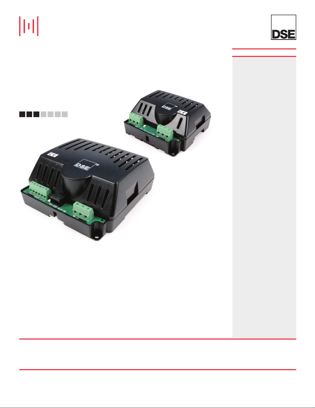
The 2 Amp, 3 Amp and 5 Amp
Battery Chargers have been
designed to be permanently
connected to a battery, keeping it
charged to maximum capacity.
The chargers can be either
mounted via DIN rail or to the
chassis, using the fixing holes that
are built into the case. The chargers
stylish design includes an LED
indicator on the front that shows
when the charger is in a normal or
overload condition.
AC
3
AM
155
T
B
AT
T
P
&
5
AM
,
DSE915
&
DSE
ERY
P
C
H
O
PT
I
O
N
S
The chargers will continue to
operate during cranking and
running. All chargers can accept
multiple AC voltage connections.
The DSE battery chargers are
expertly designed using high-grade
components and capacitors
allowing the units to function more
efficiently, providing a longer and
more reliable life-span than other
chargers in their class. Their inbuilt robustness makes them ideal
for the rigours of a wide variety of
markets including heavy and light
industrial environments.
9255
AR
G
E
R
0,
S
ENVIRONMENTAL TESTING STANDARDS
ELECTRO-MAGNETIC COMPATIBILITY
S EN 61000-6-2
B
EMC Generic Immunity Standard for
the Industrial Environment
BS EN 61000-6-4
EMC Generic Emission Standard for
the Industrial Environment
TEMPERATURE
BS EN 60068-2-1
Ab/Ae Cold Test -30 oC
BS EN 60068-2-2
Bb/Be Dry Heat +55 oC
VIBRATION
BS EN 60068-2-6
Ten sweeps in each of three
major axes
Hz to 8 Hz @ +/-7.5 mm,
5
8 Hz to 500 Hz @ 2 gn
HUMIDITY
BS EN 60068-2-30
Db Damp Heat Cyclic 20/55 oC
95% RH 48 Hours
@
S EN 60068-2-78
B
ab Damp Heat Static 40
C
@ 93% RH 48 Hours
HOCK
S
S EN 60068-2-27
B
hree shocks in each of three major axes
T
5 gn in 11 mS
1
o
C
FEATURE LIST TO SUIT A WIDE VARIETY
OF APPLICATIONS
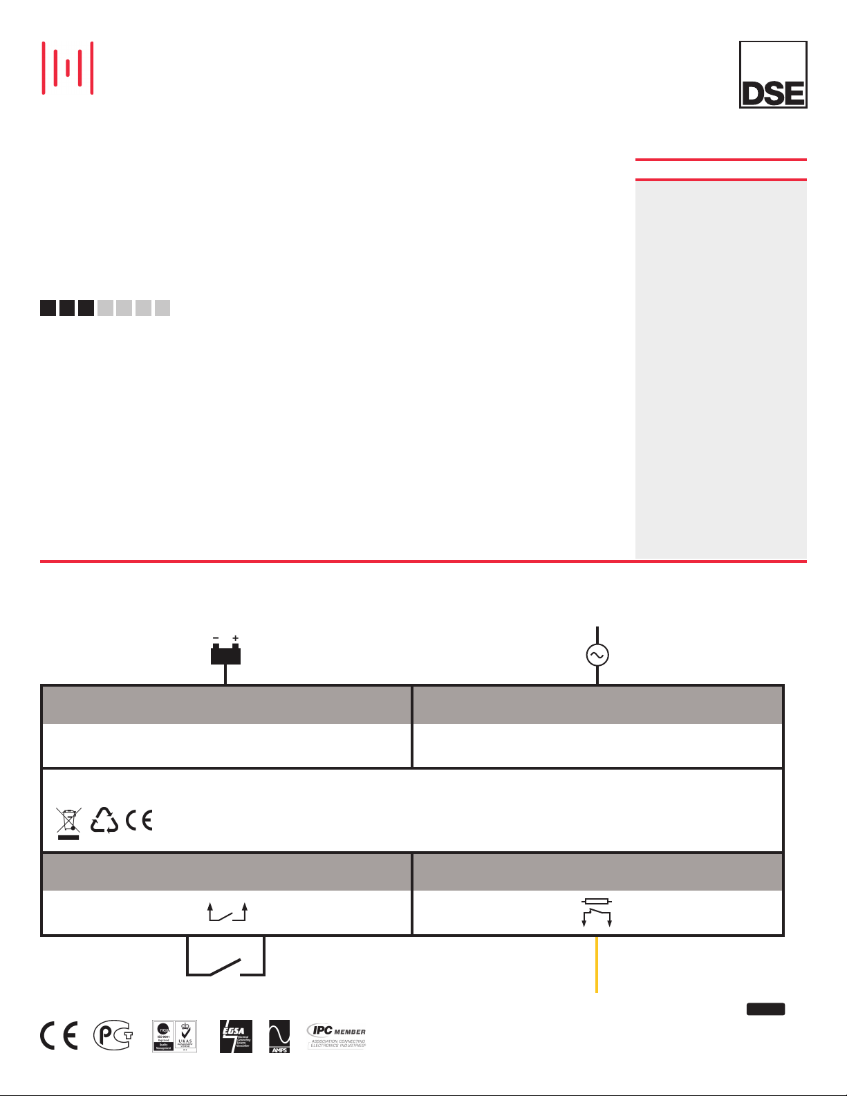
CHARGE OUTPUT AC POWER SUPPLY
COMPATIBLE WITH ALL DSE MODULES
DSE9000
CHARGE BOOST INPUT
(Not available for DSE9150 & DSE9155)
1 1
N/C VOLT FREE CHARGE FAIL OUTPUT
(Not available for DSE9150)
1ph
N
ISSUE 5
Page 2
DSE
D
S
E
9
1
3
0
D
S
E9
C
OM
P
2
A
M
P,
S
E
R
U
AT
E
F
ADVANCED FEATURES
Constant current- maximum
•
current available during charge
recovery phase
• Constant voltage
• Chargers automatically return to
float mode when charging is
complete
• Makes the chargers ideal for all
battery types
• Reverse polarity protection,
short circuit protection and
current limiting
• Automatic recovery after the
removal of fault conditions
1
5
5
A
C
T
B
AT
TE
3
A
M
P
&
5
A
M
,
D
S
E9
&
P
D
S
R
Y
C
H
O
P
T
I
O
NS
• Boosts and equalises cell
charge improving battery
performance and life
• Simple boost connection using
on-board terminals
• Once the battery is fully
charged the chargers switch to
Eco-Power to save energy
A
R
1
E9
GE
5
0
,
2
5
5
R
S
DSE9130 - 5 A 12 V
DSE9155 - 2 A 30 V
DSE9255 - 5 A 24 V
KEY BENEFITS
• Suitable for a wide range of
• No moving parts for longer
• Switched mode design
• Charge fail output
• Minimum 80% efficiency
• Multiple modules can be linked
DSE9150 - 3 A 12 V
battery types
battery charger life
throughout full operating range
together to provide larger current
output
SPECIFICATION
AC SUPPLY
FREQUENCY RANGE
48 Hz to 64 Hz
DSE9130 & DSE9255 VOLTAGE RANGE
90 V to 305 V (L-N)
DSE9150 VOLTAGE RANGE
90 V to 265 V (L-N)
DSE9155 VOLTAGE RANGE
85 V to 265 V (L-N)
DC OUTPUT
DSE9130 OUTPUT
5 A DC 12 V DC at 13.7 V DC
DSE9150 OUTPUT
3 A DC 12 V DC at 13.7 V DC
DSE9155 OUTPUT
2 A DC 30 V DC at 34.3 V DC
DSE9255 OUTPUT
5 A DC 24 V DC at 27.4 V DV
RIPPLE AND NOISE
<1%
EFFICIENCY
>80%
REGULATION
LINE
<0.001% Vo
LOAD
1% Vo
PROTECTIONS
Short Circuit
Over Voltage
Over Current
Reverse Polarity
DIMENSIONS
DSE9150 DIMENSIONS
108 mm x 101 mm x 49 mm
4.2” x 4” x 1.9”
WEIGHT
0.16 kg
DSE9130, DSE9155 & DSE9255
DIMENSIONS
136 mm x 140 mm x 63 mm
5.4” x 5.5” x 2.5”
WEIGHT
0.5 kg
OPERATING TEMPERATURE RANGE
-30 °C to +55 °C
-22 °F to +122 °F
STORAGE TEMPERATURE RANGE
-40oC to +85oC
-40 °F to +185 °F
®
RELATED MATERIALS
TITLE PART NO’S
DSE9000 Series Installation Instructions 053-049
DSE9000 Series Operator Manual 057-085
DEEP SEA ELECTRONICS PLC UK
Highfield House, Hunmanby Industrial Estate, Hunmanby YO14 0PH
TELEPHONE +44 (0) 1723 890099 FACSIMILE +44 (0) 1723 893303
EMAIL [email protected] WEBSITE www.deepseaplc.com
Deep Sea Electronics Plc maintains a policy of continuous development and reserves the right to change
the details shown on this data sheet without prior notice. The contents are intended for guidance only.
DEEP SEA ELECTRONICS INC USA
3230 Williams Avenue, Rockford, IL 61101-2668 USA
TELEPHONE +1 (815) 316 8706 FACSIMILE +1 (815) 316 8708
EMAIL [email protected] WEBSITE www.deepseausa.com
Registered in England & Wales No.01319649
VAT No.316923457
055-059/10/10 (7)
Page 3

DEEP SEA ELECTRONICS PLC
DSE9000 SERIES BATTERY CHARGER
OPERATOR MANUAL
Document Number: 057-085
Author: Ashley Senior
DSE9000 Series Battery Charger Operator Manual ISSUE 13
Page 4

DSE9000 Series Battery Charger Operator Manual
Issue
. No.
Comments
Deep Sea Electronics Plc
Highfield House
Hunmanby
North Yorkshire
YO14 0PH
ENGLAND
Sales Tel: +44 (0) 1723 890099
Sales Fax: +44 (0) 1723 893303
E-mail: [email protected]
Website: www.deepseaplc.com
DSE9000 Series Battery Charger Operator Manual
© Deep Sea Electronics Plc
All rights reserved. No part of this publication may be reproduced in any material form (including
photocopying or storing in any medium by electronic means or other) without the written permission of
the copyright holder except in accordance with the provisions of the Copyright, Designs and Patents
Act 1988.
Applications for the copyright holder’s written permission to reproduce any part of this publication
should be addressed to Deep Sea Electronics Plc at the address above.
Any reference to trademarked product names used within this publication is owned by their respective
companies.
Deep Sea Electronics Plc reserves the right to change the contents of this document without prior
notice.
Amendments since last publication
1 Added Efficiency curve of 2A charger
2 Updated specs table of 3.7A charger
3 Added 5A DSE9255 charger and 9250-002 277V input charger
7 Added DSE9155 30V 2A charger
8 Added 10A charger
8.1 Added Indication (LED) for 10A chargers
8.2 Added detail regarding -002- chargers asnd cabinet/industrial chargers
9 Added 9400 series
9.1 Corrected specs for 9140
10 Removed all DSE9400 series chargers, added DSE9470
11 Added new DSE9400 series Chargers
12 Changes to add DSE9150 12V 3A
13
Typeface : The typeface used in this document is Arial. Care should be taken not to mistake the upper
case letter I with the numeral 1. The numeral 1 has a top serif to avoid this confusion.
Updated DSE9470 and DSE9480 to -003 (MKII) and added DSE9472MKII and
DSE9481 MKII
2
Page 5

DSE9000 Series Battery Charger Operator Manual
1 BIBLIOGRAPHY .................................................................................................. 5
1.1 INSTALLATION INSTRUCTIONS ....................................................................................... 5
1.2 MANUALS .......................................................................................................................... 5
3 SPECIFICATIONS ............................................................................................... 7
3.1 PART NUMBERING ............................................................................................................ 7
3.1.1 DSE9100 CHASSIS MOUNT BATTERY CHARGERS .................................................. 7
3.1.2 DSE9200 CHASSIS MOUNT BATTERY CHARGERS .................................................. 8
3.1.3 DSE9400 MKII SERIES CHASSIS MOUNT BATTERY CHARGERS ............................ 9
3.1.4 DSE907 INDUSTRIAL / DSE908 CABINET MOUNTED BATTERY CHARGERS ........ 10
3.2 COMMON ELECTRICAL SPECIFICATIONS .................................................................... 11
3.3 COMMUNICATION PORT USAGE .................................................................................. 12
3.3.1 USB CONNECTION ................................................................................................... 12
3.3.2 RS485 ........................................................................................................................ 13
3.5 OUTPUT SPECIFICATIONS ............................................................................................. 15
3.5.1 DSE9130 12V 5A ....................................................................................................... 15
3.5.2 DSE9140 12V 10A ..................................................................................................... 16
3.5.3 DSE9150 12V 2A ....................................................................................................... 17
3.5.4 DSE9150 12V 3A ....................................................................................................... 18
3.5.5 DSE9155 30V 2A ....................................................................................................... 19
3.5.6 DSE9250 24V 3.7A .................................................................................................... 20
3.5.7 DSE9255 24V 5A ....................................................................................................... 21
3.5.8 DSE9260 24V 10A ..................................................................................................... 22
3.5.9 DSE9470 (MKII) 24V/12V 10A .................................................................................... 23
3.5.10 DSE9472 (MKII) 24V/12V 5A ...................................................................................... 25
3.5.11 DSE9480 (MKII) 12V 10A ........................................................................................... 26
3.5.12 DSE9481 (MKII) 12V 5A ............................................................................................. 28
3.6 DIMENSIONS AND MOUNTING ....................................................................................... 29
3.6.1 DSE907 12V 10A INDUSTRIAL BATTERY CHARGER .............................................. 29
3.6.2 DSE908 12V & 24V 10A CABINET MOUNTED BATTERY CHARGER ....................... 30
3.6.3 DSE9130 12V 5A ....................................................................................................... 31
3.6.4 DSE9150 12V 2A ....................................................................................................... 32
3.6.5 DSE9150 12V 3A ....................................................................................................... 33
3.6.6 DSE9140 12V 10A ..................................................................................................... 34
3.6.7 DSE9155 30V 2A ....................................................................................................... 35
3.6.8 DSE9250 24V 3.7A .................................................................................................... 36
3.6.9 DSE9255 24V 5A ....................................................................................................... 37
3.6.10 DSE9260 24V 10A ..................................................................................................... 38
3.6.11 DSE9470 (MKII) 24V/12V 10A .................................................................................... 39
3.6.12 DSE9472 (MKII) 24V/12V 5A ...................................................................................... 40
3.6.13 DSE9480 (MKII) 12V/24V 10A .................................................................................... 41
3.6.14 DSE9481 (MKII) 12V/24V 5A ...................................................................................... 42
3.7 APPLICABLE STANDARDS ............................................................................................. 43
4 INSTALLATION ................................................................................................. 44
4.1 BATTERY SUITABILITY ................................................................................................... 44
4.2 USER CONNECTIONS ..................................................................................................... 44
4.2.1 DSE9130, DSE9140, DSE9250, DSE9255 & DSE9260 .............................................. 45
4.2.2 DSE9150 .................................................................................................................... 45
4.2.3 DSE9155 .................................................................................................................... 46
4.2.4 DSE9470 MKII, DSE9472 MKII, DSE9480 MKII, DSE9481 MKII .............................. 47
4.3 TYPICAL WIRING DIAGRAM ........................................................................................... 49
4.3.1 DSE9150 .................................................................................................................... 49
4.3.2 DSE9155 & DSE9200 SERIES ................................................................................... 50
4.3.3 DSE9470 MKII, DSE9472 MKII, DSE9480 MKII, DSE9481 MKII ............................... 51
5 INDICATIONS .................................................................................................... 52
5.1 DSE907............................................................................................................................. 52
5.2 DSE908............................................................................................................................. 52
5.3 DSE9130, DSE9150, DSE9155, DSE9250 & DSE9255 ..................................................... 53
5.4 DSE9140 & DSE9260 ....................................................................................................... 54
3
Page 6

DSE9000 Series Battery Charger Operator Manual
5.5 DSE9470 MKII, DSE9472 MKII, DSE9480 MKII, DSE9481 MKII ....................................... 55
5.5.1 STATUS ..................................................................................................................... 55
5.5.2 CHARGE MODE ........................................................................................................ 55
5.5.3 FAULT CONDITIONS ................................................................................................. 55
6 OPERATION ...................................................................................................... 56
6.1 OPERATION OF DSE9100 SERIES / DSE9200 SERIES .................................................. 56
6.1.1 PROTECTION ............................................................................................................ 56
6.1.2 PSU MODE ................................................................................................................ 56
6.1.3 CHARGE MODE ........................................................................................................ 56
6.1.4 BOOST MODE ........................................................................................................... 57
6.2 OPERATION OF DSE9400 MKII SERIES ......................................................................... 58
6.2.1 PROTECTION ............................................................................................................ 58
6.2.2 DIGITAL INPUT .......................................................................................................... 59
6.2.3 VOLTAGE ADJUSTMENT POTENTIOMETER ........................................................... 59
6.2.4 PSU MODE ................................................................................................................ 59
6.2.5 CHARGE MODE ........................................................................................................ 60
6.2.6 TEMPERATURE COMPENSATION ........................................................................... 61
7 FAULT DIAGNOSIS ........................................................................................... 62
8 MAINTENANCE, SPARES, REPAIR AND SERVICING ................................... 63
9 WARRANTY ...................................................................................................... 63
10 DISPOSAL ...................................................................................................... 63
10.1
WEEE (WASTE ELECTRICAL AND ELECTRONIC EQUIPMENT) ............................... 63
10.2
ROHS (RESTRICTION OF HAZARDOUS SUBSTANCES) ........................................... 63
4
Page 7

Bibliography
DSE PART
DESCRIPTION
DSE PART
DESCRIPTION
1 BIBLIOGRAPHY
This document refers to and is referred to by the following DSE publications which can be obtained
from the DSE website www.deepseaplc.com
1.1 INSTALLATION INSTRUCTIONS
Installation instructions are supplied with the product in the box and are intended as a ‘quick start’
guide only.
053-049 DSE9200 / DSE9400 Series Battery Charger Installation Instructions
053-123 DSE9150 Battery Charger Installation Instructions
1.2 MANUALS
057-159 DSE9400 Series Battery Charger Configuration Suite Manual
5
Page 8

Introduction
2 INTRODUCTION
NOTE: This document DOES NOT contain details of the ‘obsolete’ DSE9210 and DSE9240
battery chargers. For further details of these units, please contact Deep Sea Electronics.
This document details the installation requirements of the DSE9000 series range of battery chargers.
The manual forms part of the product and should be kept for the entire life of the product. If the
product is passed or supplied to another party, ensure that this document is passed to them for
reference purposes.
This is not a controlled document. You will not be automatically informed of updates. Any future
updates of this document will be added to the DSE website at www.deepseaplc.com.
The DSE9000 series modules are intended for mounting within a customer enclosure or panel (DIN
rail mounting or fastened by screws/bolts).
DSE also supply some of the battery chargers as completed units, factory mounted into enclosures for
wall or floor mounting.
The DSE9000 series chargers fulfill the most common functions required of a charger in the
generating set industry. Combining protected outputs, intelligent charging and power supply operation
with a robust enclosure.
6
Page 9

Specifications
3 SPECIFICATIONS
3.1 PART NUMBERING
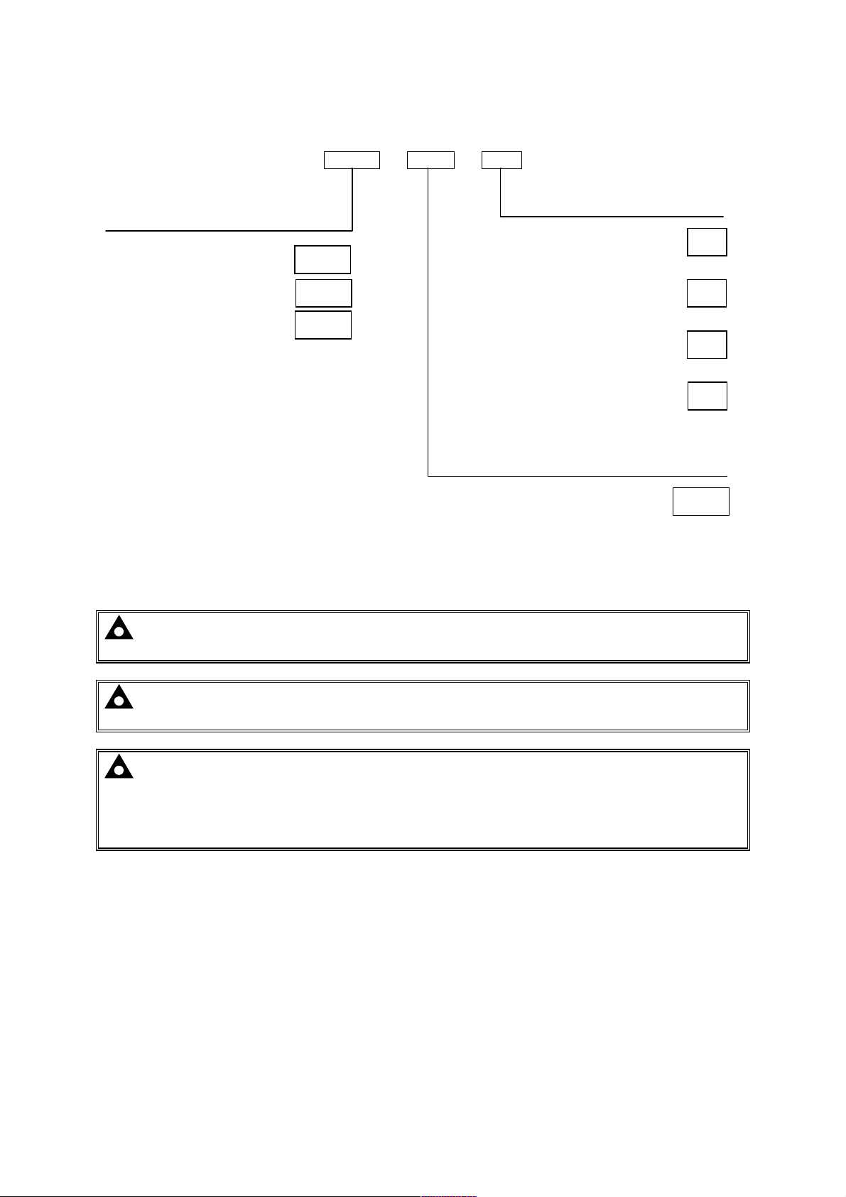
3.1.1 DSE9100 CHASSIS MOUNT BATTERY CHARGERS
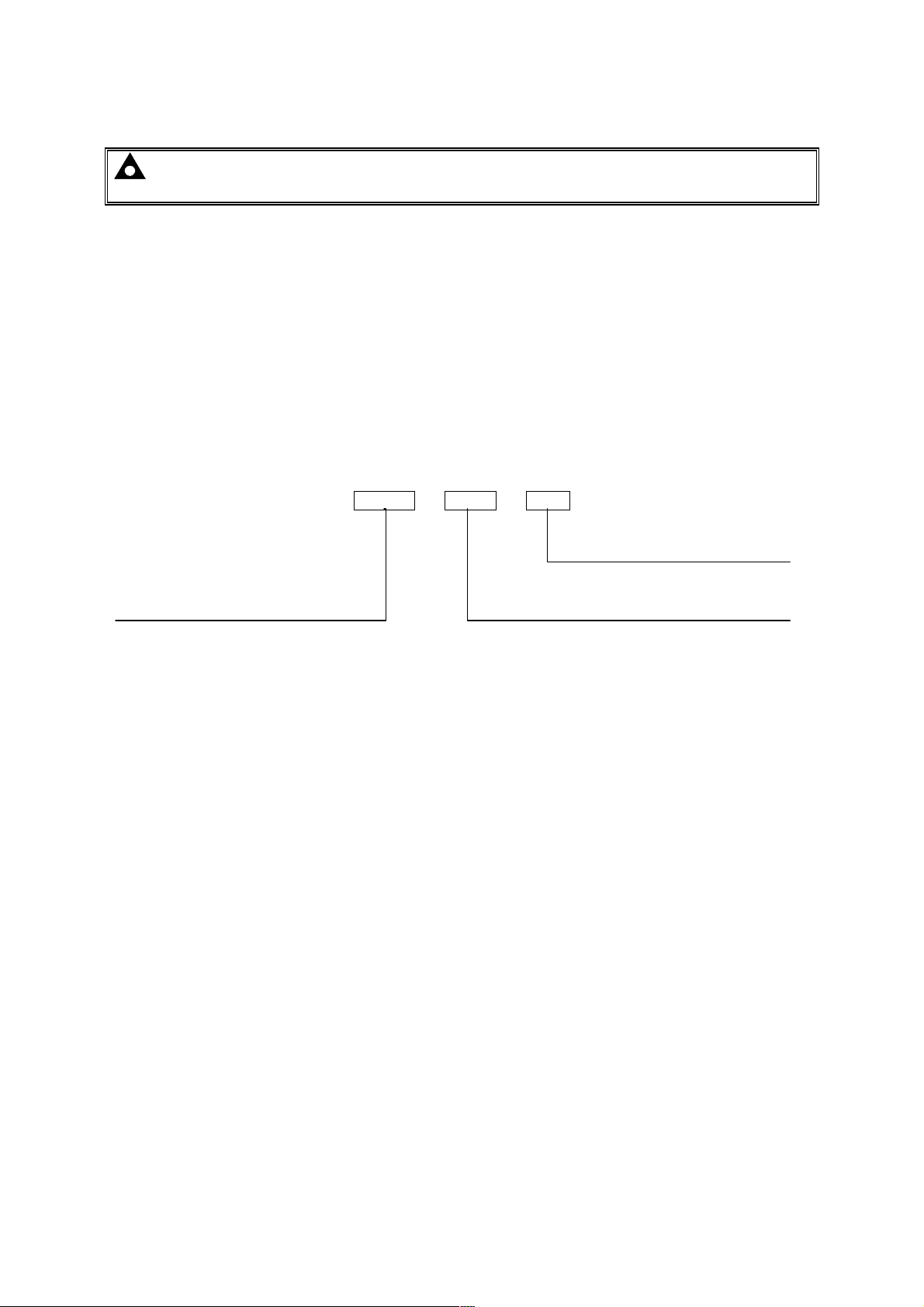
9130 - 001 - 00
Product type
DSE9130 12V 5A
DSE9140 12V 10A
DSE9150 12V 2A
DSE9150 12V 3A
DSE9155 30V 2A
9130
9140
9150
9150
9155
For 9 or 18 cell NICAD batteries*
For 10 or 20 cell NICAD batteries*
Specify required float voltage on ordering**
For lead acid batteries
12V charger s et to 13.7V
24V charger s et to 27.4V
12V charger s et to 13.0V
24V charger s et to 26.0V
12V charger s et to 14.5V
24V charger s et to 29.0V
For other battery types*
Hardware revisions
First version hardware
Variant
00
01
02
03
001
NOTE: For descriptions of other Hardware Revisions, please contact
NOTE: The DSE9150 12V 2A is now obsolete, replaced with DSE9150 12V 3A.
NOTE: The DSE9150 12V 3A only available in Variant -00 (13.7V for lead acid batteries)
NOTE: For variant 03 (For other battery types), the float voltage can be adjusted between
12.5V and 15V for DSE9130 12V 5A chargers (25V - 30V for DSE9250 24V 3.7A chargers). This
change must be made at the DSE factory. Ensure the correct variant (and float voltage if
applicable) is specified on ordering. Consult your battery manufacturer for further details of
required float voltage.
7
Page 10
Specifications
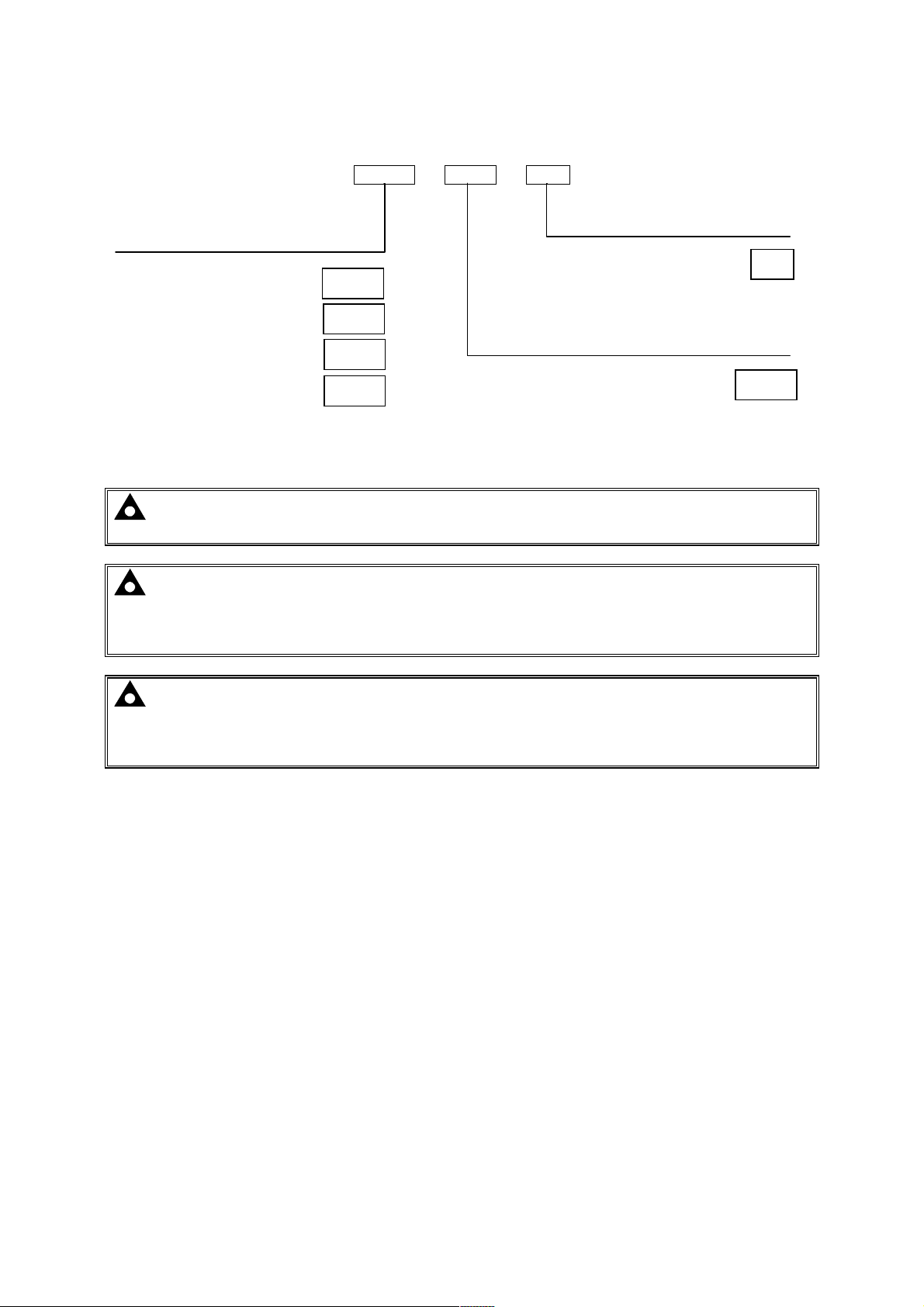
3.1.2 DSE9200 CHASSIS MOUNT BATTERY CHARGERS
9130 - 001 - 00
Product type
DSE9250 24V 3.7A
DSE9255 24V 5A
9250
9255
For 9 or 18 cell NICAD batteries*
DSE9260 24V 10A
9260
For 10 or 20 cell NICAD batteries*
Specify required float voltage on ordering**
For lead acid batteries
12V charger s et to 13.7V
24V charger s et to 27.4V
12V charger s et to 13.0V
24V charger s et to 26.0V
12V charger s et to 14.5V
24V charger s et to 29.0V
For other battery types*
Hardware revisions
First version hardware
Variant
00
01
02
03
001
NOTE: For descriptions of other Hardware Revisions, please contact
NOTE: - The DSE9250 battery charger is now obsolete, details provided for information
only.
NOTE: For variant 03 (For other battery types), the float voltage can be adjusted between
12.5V and 15V for DSE9130 12V 5A chargers (25V - 30V for DSE9250 24V 3.7A chargers). This
change must be made at the DSE factory. Ensure the correct variant (and float voltage if
applicable) is specified on ordering. Consult your battery manufacturer for further details of
required float voltage.
8
Page 11
Specifications
3.1.3 DSE9400 MKII SERIES CHASSIS MOUNT BATTERY CHARGERS
9470 - 001 - 00
Product type
DSE9470 12/24V 10A
DSE9472 24V/12V 5A
DSE9480 24V/12V 10A 9480
DSE9481 24V/12V 5A 9481
NOTE: For descriptions of other Hardware Revisions, please contact
9470
9472
First v ersion hardware 001
Variant
Standard
Hardware revisions
00
NOTE: For hardware versions 003 and above, voltage and current levels can be user
configured via DSE Configuration Suite PC Software.
Part number 9470-001-00 is fixed at 24V 10A.
Part number 9480-001-00 is fixed at 12V 10A.
NOTE: DSE9400 series battery chargers are customer configurable via the DSE
Configuration Suite PC Software.
For further details, you are referred to DSE Publication: 057-159 DSE9400 Series Battery
Charger Configuration Suite Manual.
9
Page 12
Specifications
02
11
3.1.4 DSE907 INDUSTRIAL / DSE908 CABINET MOUNTED BATTERY CHARGERS
NOTE: The DSE907 / DSE908 Industrial / Cabinet Mounted Battery Chargers are now
obsolete, replaced by DSE9460 / DSE9461 Enclosed Battery Chargers.
See the preceeding page for details of part numbering of chassis mounted battery chargers.
Industrial / Cabinet mounted battery chargers are 9000 series battery chargers factory fitted into wall
mounted enclosures. For details see the section entitled Dimensions and Mounting elsewhere in
this document.
0907-002-
0908-001-
INDUSTRIAL BATTERY CHARGER 12V 5A 220-250V
CABINET MOUNTED BATTERY CHARGER 12V 10A
0908-001-21 CABINET MOUNTED BATTERY CHARGER 24V 10A
0907 - 001 - 00
Variant
Product type
Hardware revisions
When ordering Industrial / Cabinet mounted battery chargers, ensure you specify the type of batteries
that are to be charged. If you do not specify this, the chargers will be preset to charge Lead Acid type
batteries.
10
Page 13
Specifications
Parameter
Min Nominal
Max AC
Input Voltage (V)
Input F
requency (Hz)
Line
R
egulation
Output
V
oltage
O
vershoot %
Transient Response Peak D
eviation (mV)
Warm Up V
oltage (V)
Short Circuit P
rotection
Switching
F
requency (k
Hz)
Efficiency %
Temperature Sensor
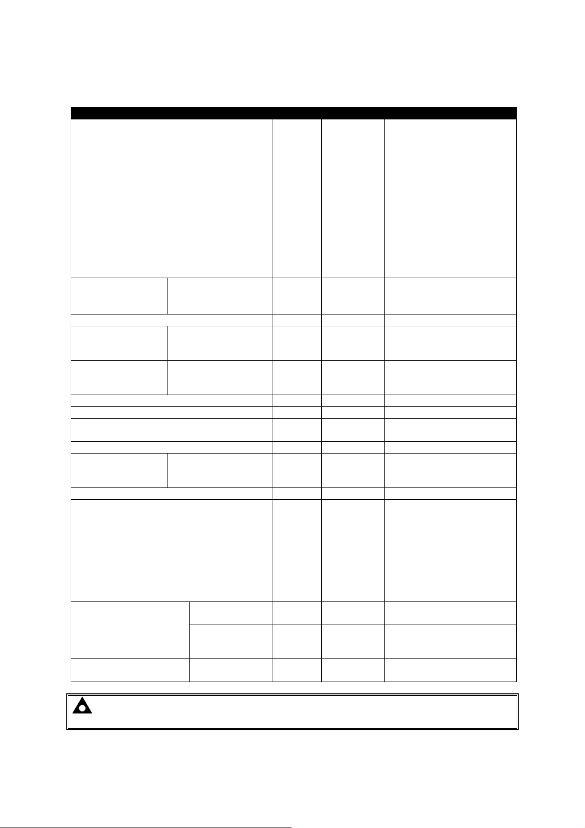
3.2 COMMON ELECTRICAL SPECIFICATIONS
DSE9130 12V 5A
DSE9150 12V 2A
DSE9150 12V 3A
DSE9140 12V 10A
DSE9155 30V 2A
DSE9250 24V 3.7A (9250-001-xx)
DSE9250 24V 3.7A (9250-002-xx)
DSE9255 24V 5A
DSE9260 24V 10A
DSE9470 24V/12V 10A
DSE9472 24V 5A
DSE9480 12V/24V 10A
DSE9481 12V 5A
Operating
Temperature
Output Ripple and
Noise
Load Regulation
(at 50% to 100% load step)
Output Voltage
Rise Time (ms)
9130-001-xx (replaced with 9130-002-xx)
9250-001-xx (replaced with 9250-002-xx)
(See section entitled
‘output specifications’
elsewhere in this
manual)
DSE9100 Series
DSE9200 Series
DSE9400 Series
DSE9100 Series
DSE9200 Series
DSE9400 Series
DSE9100 Series
DSE9200 Series
DSE9400 Series
DSE9100 Series
DSE9200 Series
DSE9400 Series
9130-002-xx
9250-002-xx
94xx-xxx-xx
All other chargers
DSE9100 Series
DSE9200 Series
DSE9400 Series
90V
90V
90V
90V
85V
90V
90V
90V
90V
95V
95V
95V
95V
-30°C
-30°C
-30°C
48Hz 64Hz
1% Vo
1% Vo
<0.01% Vo
<5%Vo
<1% Vo
<100ms
Hiccup
>80%
110V-277V
110V-240V
110V-240V
110V-240V
110V-240V
110V-240V
110V-277V
110V-277V
110V-277V
110V-277V
110V-277V
110V-277V
110V-277V
2% Vo
1% Vo
2% Vo
1% Vo
<4% Vo
<100ms
<200ms
100kHz
100kHz
67kHz
67kHz
67kHz
100kHz
>85%
85°C with de-ratings
304V
250V
265V
277V
265V
265V
305V
305V
305V
305V
305V
305V
305V
55°C
55°C
Input
NOTE: Check the DSE9400 Series de-rating curves which can be found else where in this
manual for more information.
DSE9400 Series
PT1000
11
Page 14

Specifications
Communication
Specification
USB Port
•
3.3 COMMUNICATION PORT USAGE
(DSE9400 series
only)
USB2.0 Device for connection to PC running DSE Configuration Suite
Max distance 6m (20 feet)
Isolated
Data connection 2 wire + common
RS485 Serial
Port
(DSE9400 series
only)
Half Duplex
Data direction control for Transmit (by s/w protocol)
Max Baud Rate 19200
External termination required (120Ω)
Max common mode offset 70V (on board protection transorb)
Max distance 1.2km (¾ mile)
3.3.1 USB CONNECTION
The USB port is provided to give a simple means of connection between a PC and the DSE9400
series battery charger. Using the DSE Configuration Suite Software, the operator is then configure
and monitor the state of the battery charger.
To connect a DSE9400 series battery charger to a PC by USB, the following items are required:
• DSE9400 series battery charger
• DSE Configuration Suite Software
(Supplied on configuration suite software CD or available from
www.deepseaplc.com).
USB cable Type A to Type B.
(This is the same cable as often used between a PC and a USB
printer)
DSE can supply this cable if required :
PC Configuration interface lead (USB type A – type B) DSE Part
No 016-125
NOTE: - Refer to DSE9400 Series Battery Charger PC Software Configuration Manual for
further details on configuring and monitoring.
12
Page 15
Specifications
3.3.2 RS485
The RS485 port on the DSE9400 series battery chargers has two uses.
1) Supporting the DSE2541 remote battery charger display module (MKII only)
2) Support the Modbus RTU protocol for connection to a Modbus RTU Master device.
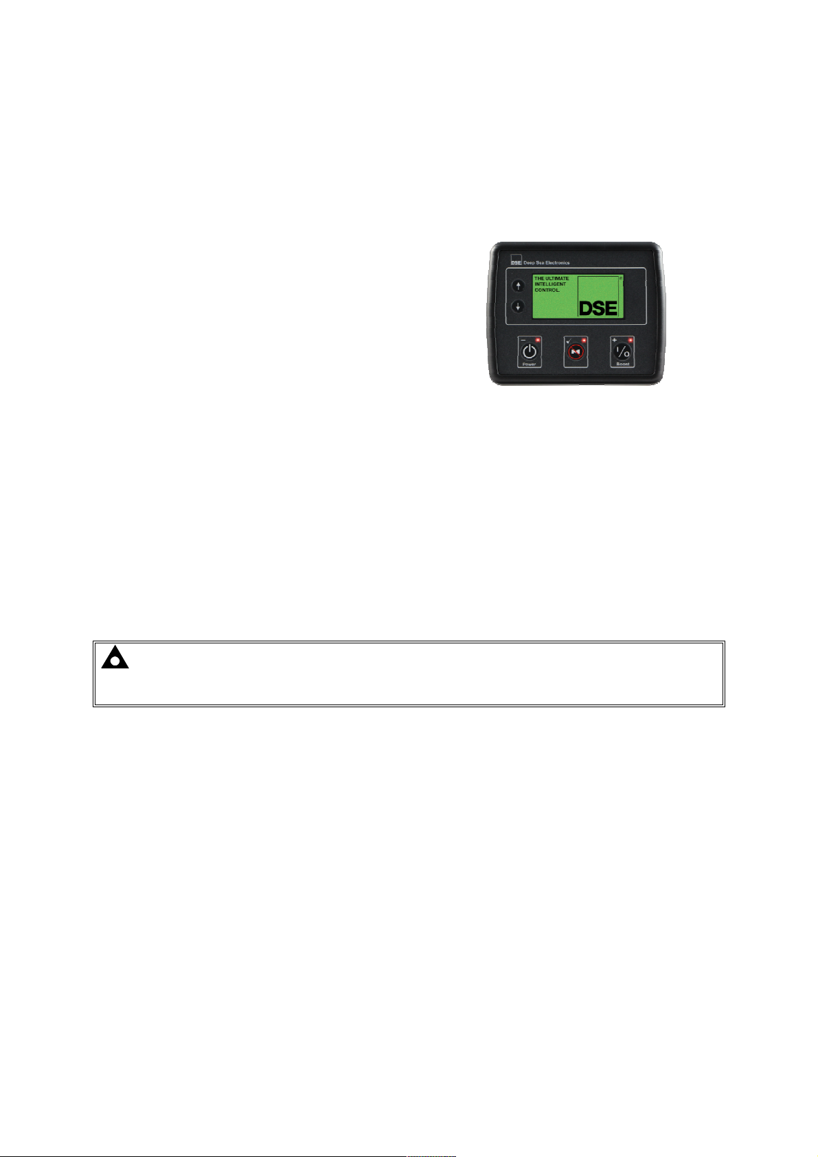
3.3.2.1 DSE2541 REMOTE BATTERY CHARGER DISPLAY MODULE
DSE2541 remote battery charger display modules
connects to the DSE9400 MKII Series battery
charger RS485 terminals.
This provides battery charger operating status, alarm
indication, instrumentation and control over the
DSE9400 MKII Series battery charger.
For further information please contact
[email protected].
3.3.2.2 MODBUS RTU
RS485 is used for point-to-point cable connection of more than one device (maximum 32 devices)
and allows for connection to PCs, PLCs and Building Management Systems (to name just a few
devices).
Using the DSE Configuration Suite PC Software, Configurable Gencomm is used to map
instrumentation to modbus registers.
One advantage of the RS485 interface is the large distance specification (1.2km) when using Belden
9841 (or equivalent) cable. This allows for a large distance between the DSE9400 series battery
charger and a PC running the DSE Configuration Suite software. The operator is then able to view the
various operating parameters.
NOTE: - For distances up to 6m (8yds) the USB connection method is more suitable and
provides for a lower cost alternative to RS485 (which is more suited to longer distance
connections).
13
Page 16
Specifications
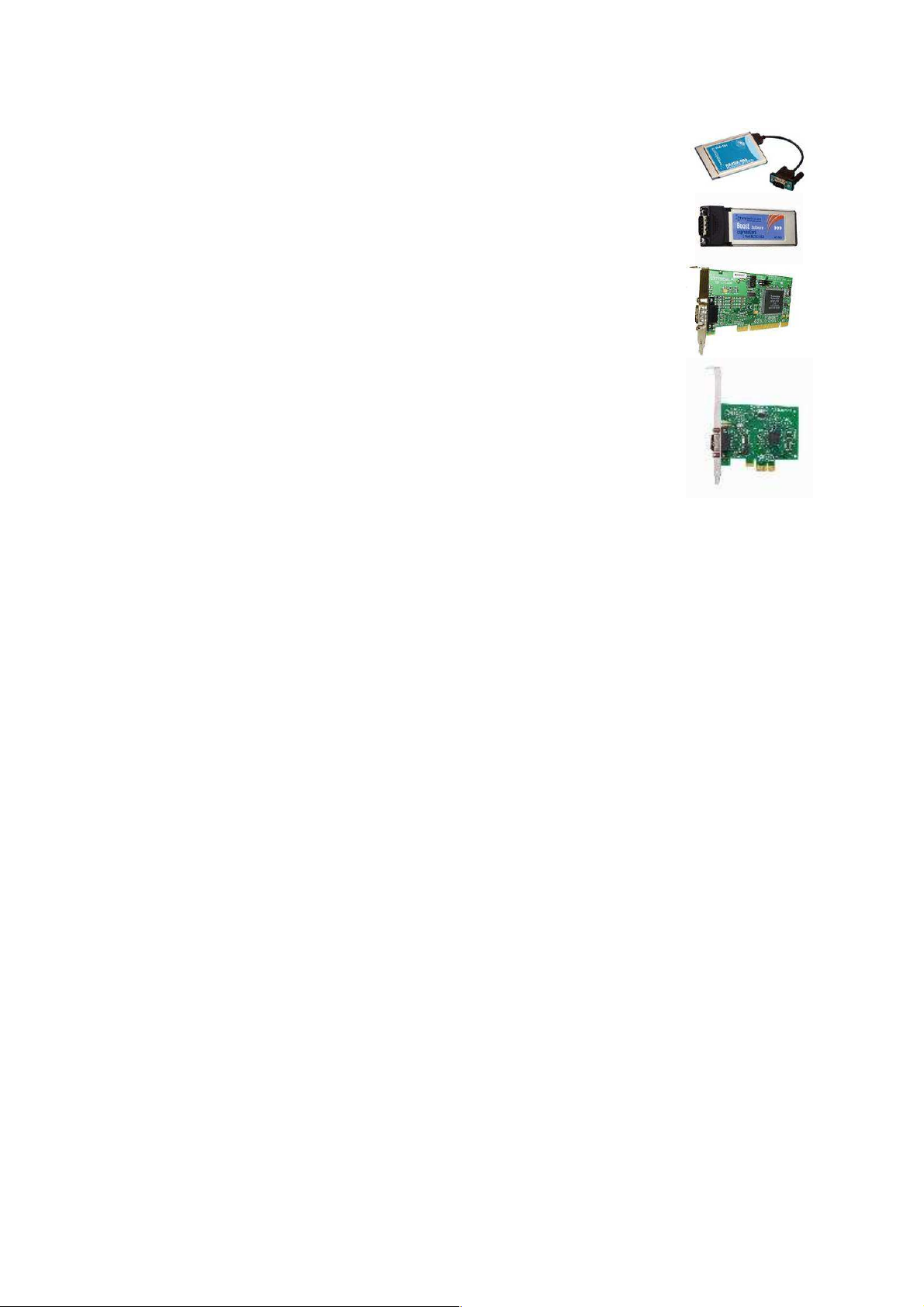
3.3.2.3 OPTIONS FOR CONNECTION TO PCS
• Brainboxes PM154 PCMCIA RS485 card (for laptops PCs)
Set to ‘Half Duplex, Autogating” with ‘CTS True’ set to ‘enabled’
• Brainboxes VX-023 ExpressCard 1 Port RS422/485 (for laptops and
nettop PCs)
• Brainboxes UC320 PCI Velocity RS485 card (for desktop PCs)
Set to ‘Half Duplex, Autogating” with ‘CTS True’ set to ‘enabled’
• Brainboxes PX-324 PCI Express 1 Port RS422/485 (for desktop PCs)
Supplier:
14
Page 17

Specifications
Parameter
Min Nominal
Max Comments
3.5 OUTPUT SPECIFICATIONS
3.5.1 DSE9130 12V 5A
Output Voltage (12 V DC battery) 12.5V 13.7V 15.0V Specify float voltage on ordering.
Output Charging Current (A) 0A 5A 5.5A
Current limit threshold (A) 5A 5.3A 5.5A
Recovery from current limit (A) 5A
Full load AC input current (A) 1.5A With output at 13.7V DC
AC Input Inrush (10ms) current (A) 20A
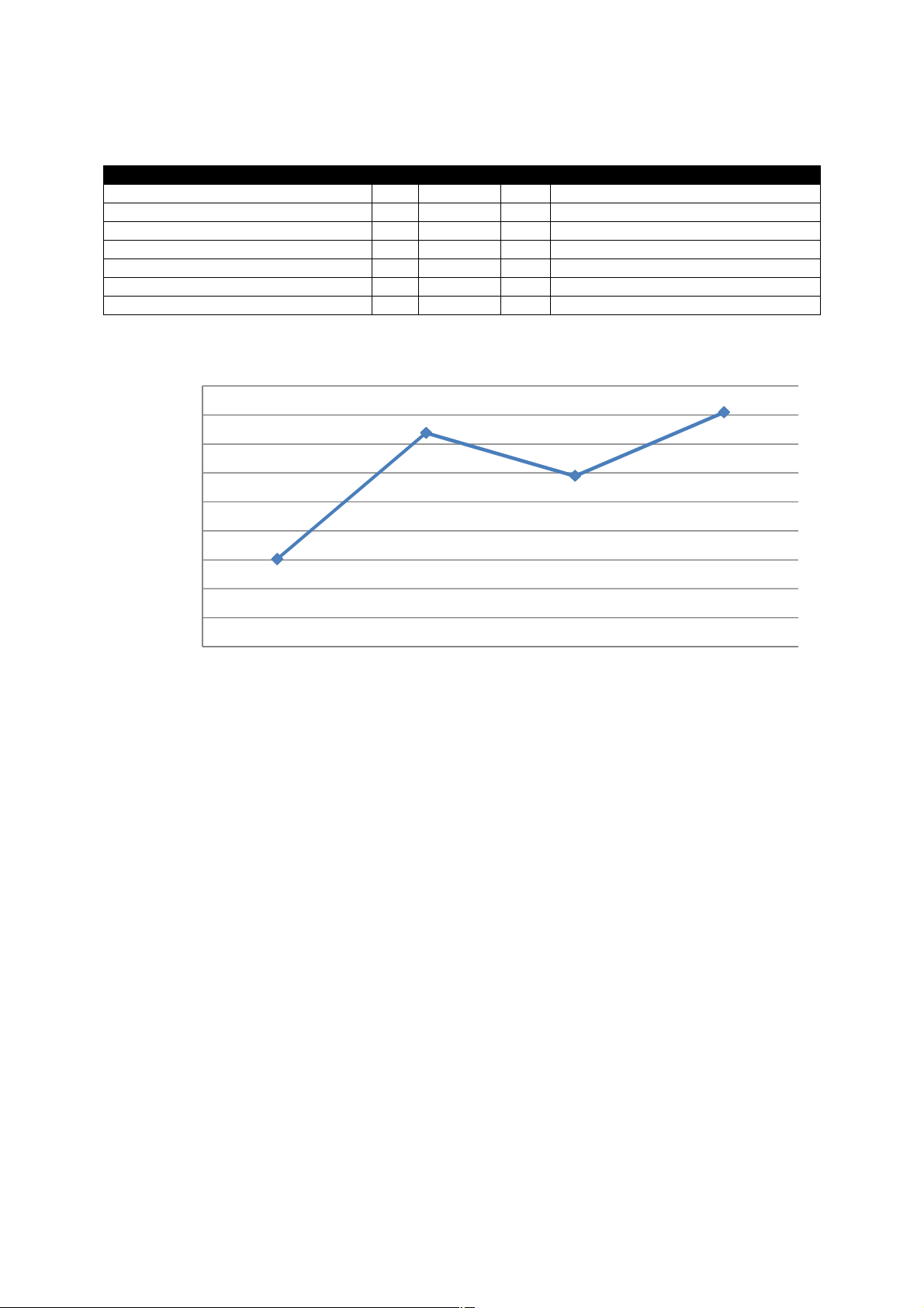
DSE9130 Efficiency Curve at 5A
0.92
0.9
0.88
0.86
0.84
Efficiency (%)
0.82
0.8
85 110 230 260
Input Voltage (V)
15
Page 18
Specifications
Parameter
Min Nominal
Max Comments
85
110
230
260
3.5.2 DSE9140 12V 10A
Output Voltage (12 V DC Battery) 12V 13.7V 15V
Output Charging Current (A) 10A 10A 11A
Current limit threshold (A) 10A 11A
Recovery from current limit (A) 10A 11A
Full load AC input current (A) 3.1A At Vin=85V, Vo=13.7V, Io=10Am p
Full load AC input current (A) 1.3A At Vin=230V, Vo=13.7V Io=10Amp
AC Input Inrush (10ms) current (A) 60A
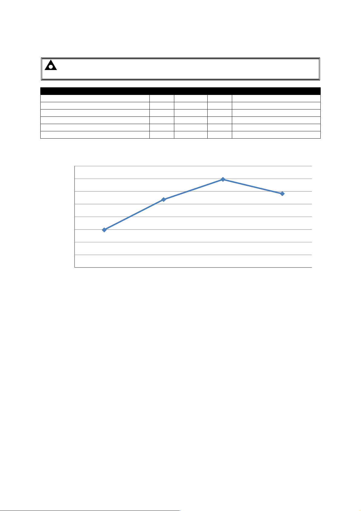
DSE9140 Efficiency Curve at 10A
0.87
0.86
0.85
0.84
0.83
0.82
0.81
Efficiency (%)
0.8
0.79
0.78
Input Voltage (V)
16
Page 19
Specifications
Parameter
Min Nominal
Max Comments
3.5.3 DSE9150 12V 2A
NOTE: This device is no longer available, replaced by DSE9150 12V 3A. See overleaf for
updated specifications.
Output Voltage (12 V DC Battery) 12.5V 13.7V 13.7V Float voltage not adjustable
Output Charging Current (A) 0A 2A 2.5A
Current limit threshold (A) 2A 2.3A 2.5A
Recovery from current limit (A) 2A
Full load AC input current (A) 0.7A With output at 13.7V DC
AC Input Inrush (10ms) current (A) 10A
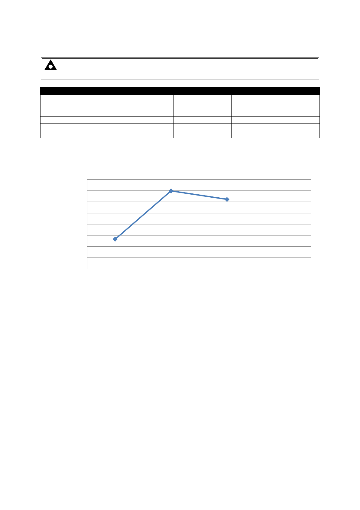
DSE9150 Efficiency Curve at 2A
90
88
86
84
82
80
Efficiency (%)
78
76
74
85 110 230 250
Input Voltage (V)
17
Page 20
Specifications
Parameter
Min Nominal
Max Comments
3.5.4 DSE9150 12V 3A
NOTE: This device has replaced DSE9150 12V 2A. See previous page for specifications of
the earlier model.
Output Voltage (12 V DC Battery) 12.5V 13.7V 13.7V Float voltage not adjustable
Output Charging Current (A) 0A 3A 3.5A
Current limit threshold (A) 3A 3.2A 3.5A
Recovery from current limit (A) 3A
Full load AC input current (A) 0.7A With output at 13.7V DC
AC Input Inrush (10ms) current (A) 10A
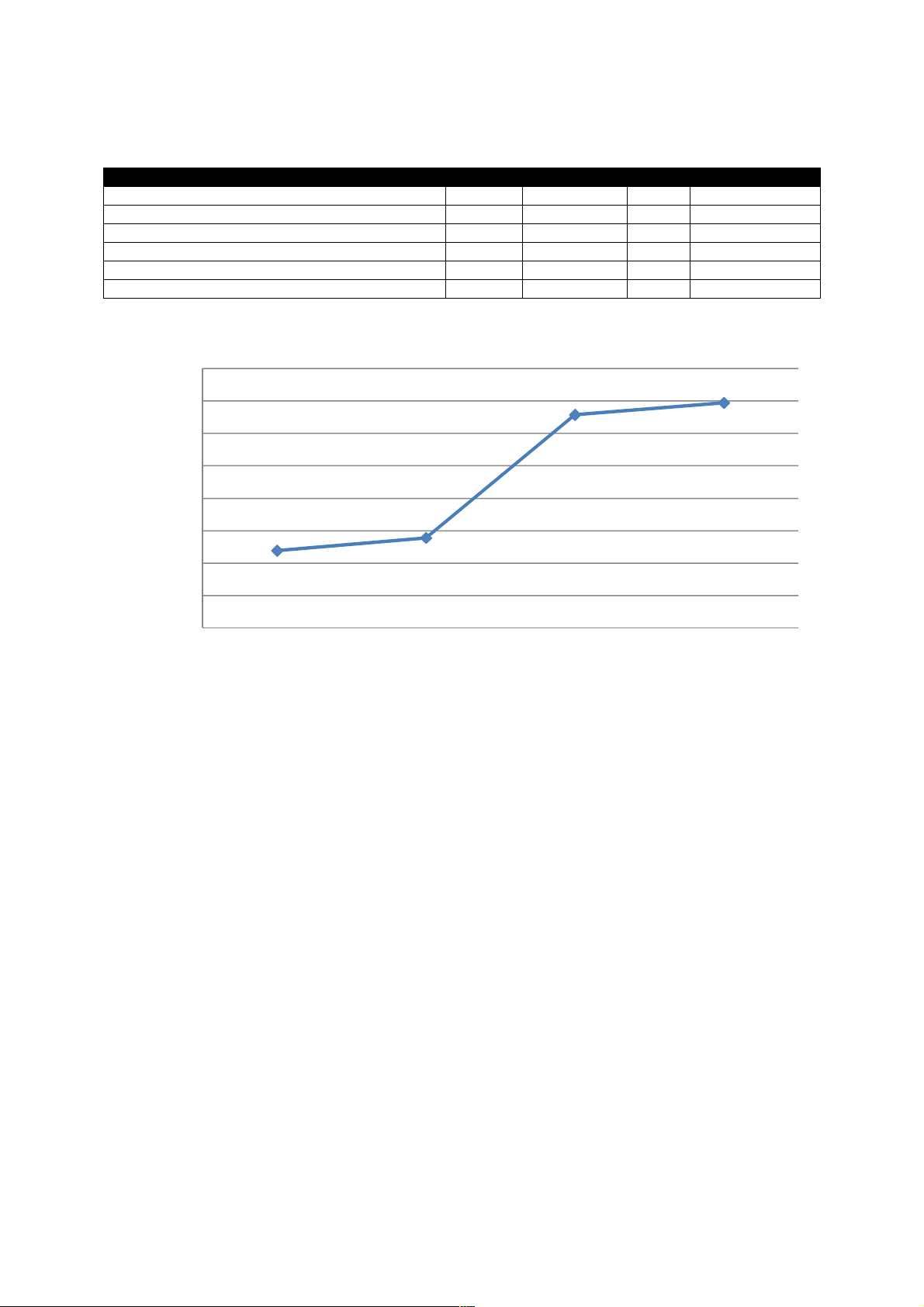
DSE9153 Efficiency Curve at 3A
0.87
0.86
0.85
0.84
0.83
0.82
Efficiency (%)
0.81
0.80
0.79
110 230 265
Input Voltage (V)
18
Page 21
Specifications
Parameter
Min Nominal
Max Comments
3.5.5 DSE9155 30V 2A
Output Voltage (30 V DC Battery) 28.0V 34.3V 34.5
Output Charging Current (A) 0A 2.2A 3A
Current limit threshold (A) 2A 2.2A 3A
Recovery from current limit (A) 2A
Full load AC input current (A) 2A
AC Input Inrush (10ms) current (A) 30A
DSE9155 Efficiency Curve at 2A
0.94
0.92
0.9
0.88
0.86
Efficiency (%)
0.84
0.82
0.8
0.78
85 110 230 260
Input Voltage (V)
19
Page 22
Specifications
Parameter
Min Nominal
Max Comments
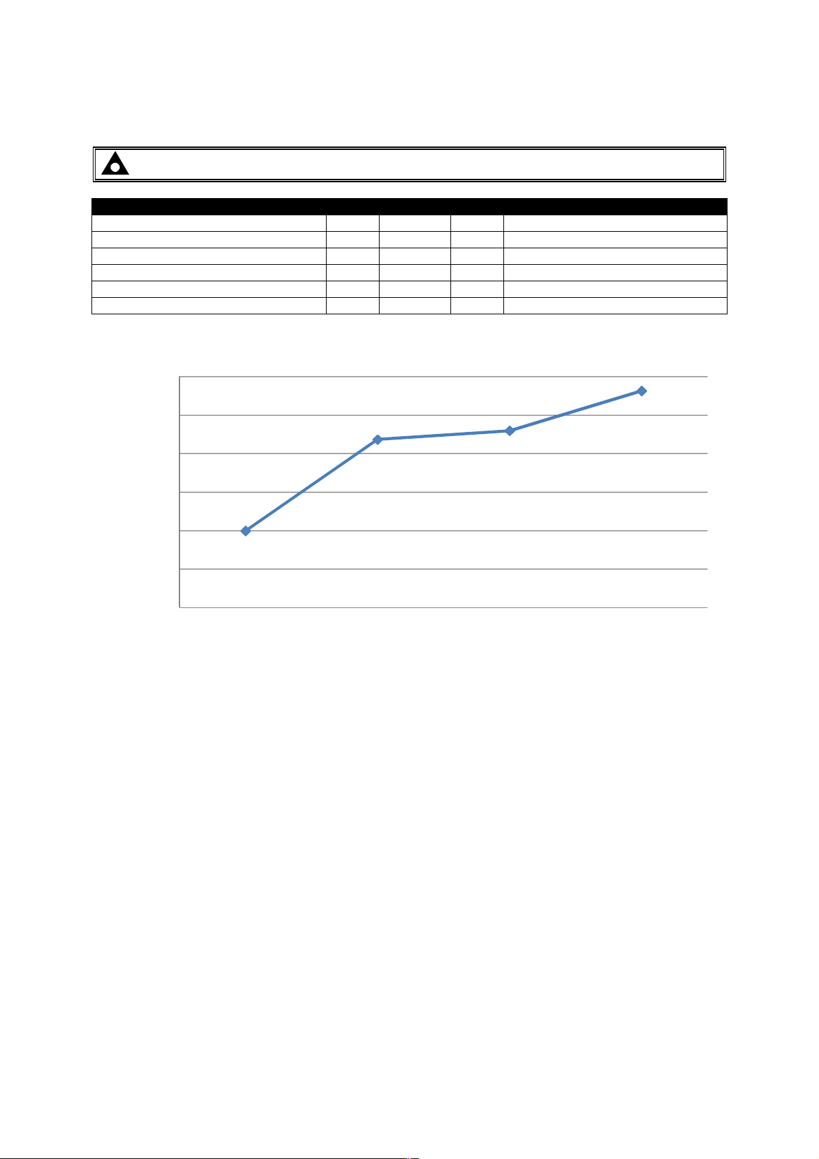
3.5.6 DSE9250 24V 3.7A
NOTE: - This battery charger is now obsolete, details provided for information only.
Output Voltage (24 V DC Battery) 25.0V 27.4V 30.0V Specify float voltage on ordering.
Output Charging Current (A) 0A 3.7A 4A
Current limit threshold (A) 3.6A 3.75A 4A
Recovery from current limit (A) 3.6A
Full load AC input current (A) 2A With output at 27.6V DC
AC Input Inrush (10ms) current (A) 30A
DSE9250 Efficiency Curve at 3.7A
0.92
0.9
0.88
0.86
0.84
Efficiency (%)
0.82
0.8
85 110 230 260
Input Voltage (V)
20
Page 23
Specifications
Parameter
Min Nominal
Max Comments
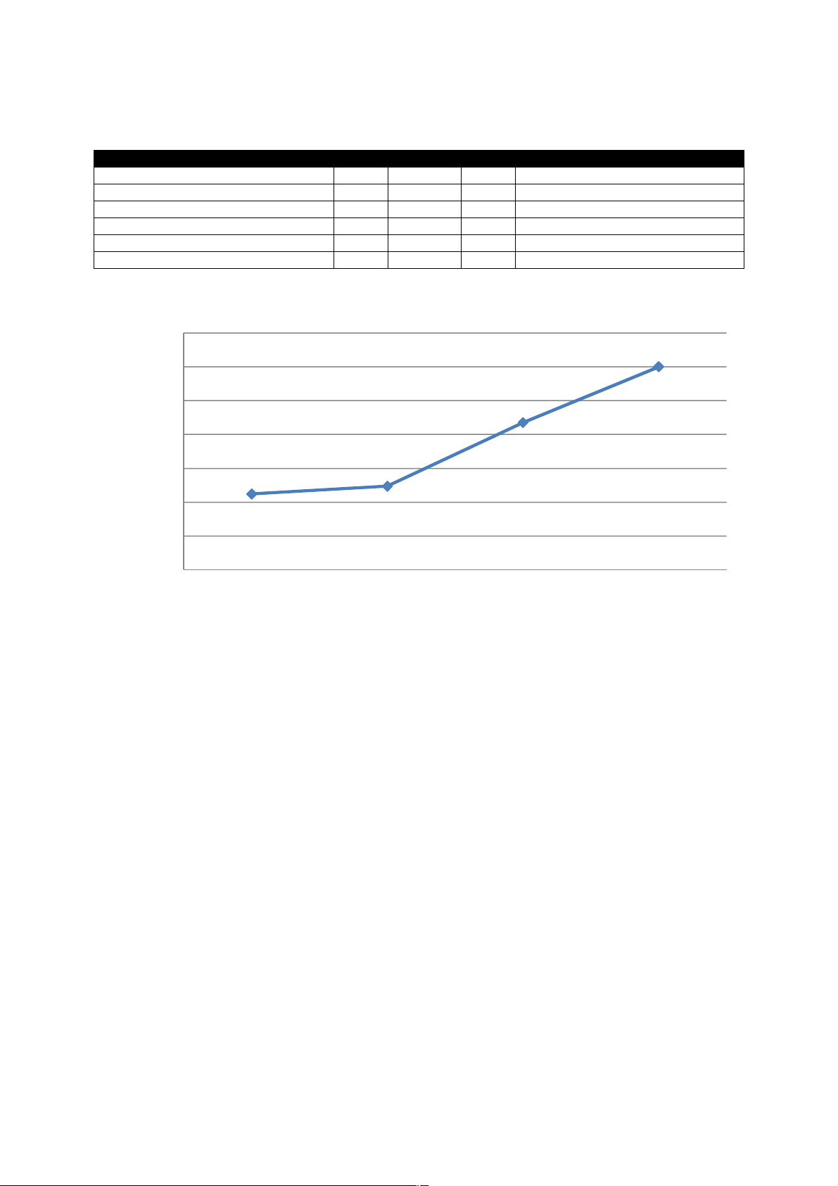
3.5.7 DSE9255 24V 5A
Output Voltage (24 V DC Battery) 25.0V 27.4V 30.0V Specify float voltage on ordering.
Output Charging Current (A) 0A 5A
Current limit threshold (A) 5A 5.3A 6A
Recovery from current limit (A) 5A 5.2A
Full load AC input current (A) 0.65A 2.7A With output at 27.6V DC
AC Input Inrush (10ms) current (A) 30A
DSE9255 Efficiency Curve at 5A
0.94
0.92
0.9
0.88
0.86
Efficiency (%)
0.84
0.82
0.8
85 110 230 260
Input Voltage (V)
21
Page 24
Specifications
Parameter
Min Nominal
Max Comments
85
110
230
265
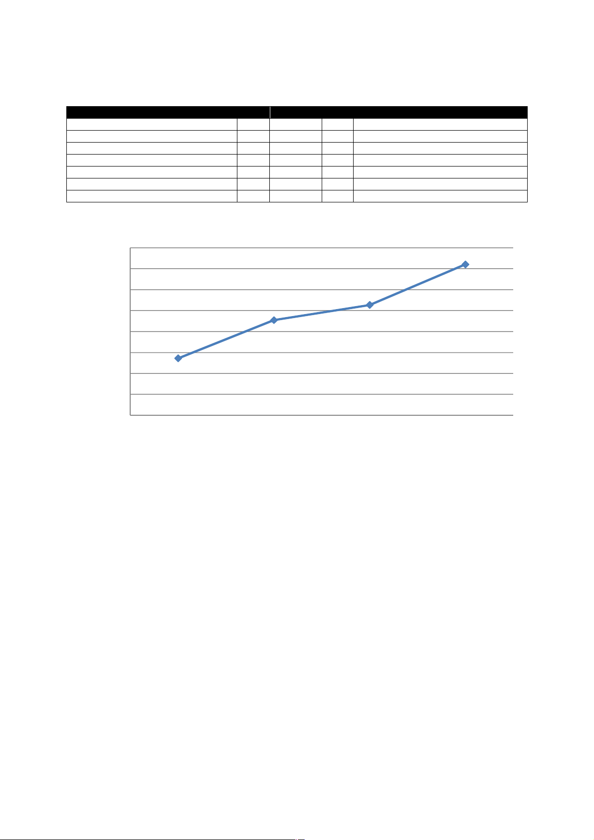
3.5.8 DSE9260 24V 10A
Output Voltage (12V DC Battery) 26V 27.6V 29V
Output Charging Current (A) 10A 11A
Current limit threshold (A) 10A 11A
Recovery from current limit (A) 9.5A 10A 11A
Full load AC input current (A) 2.2A At Vin=230V, Vo=27.6V, Io=10Amp
Full load AC input current (A) 5.8A At Vin=85V, Vo=27.6V, Io=10Amp
AC Input Inrush (10ms) current (A) 60A For 10ms
DSE9260 Efficiency Curve at 10A
0.94
0.92
0.9
0.88
0.86
0.84
Efficiency (%)
0.82
0.8
0.78
Input Voltage (V)
22
Page 25
Specifications
Parameter
Min Nominal
Max Comments
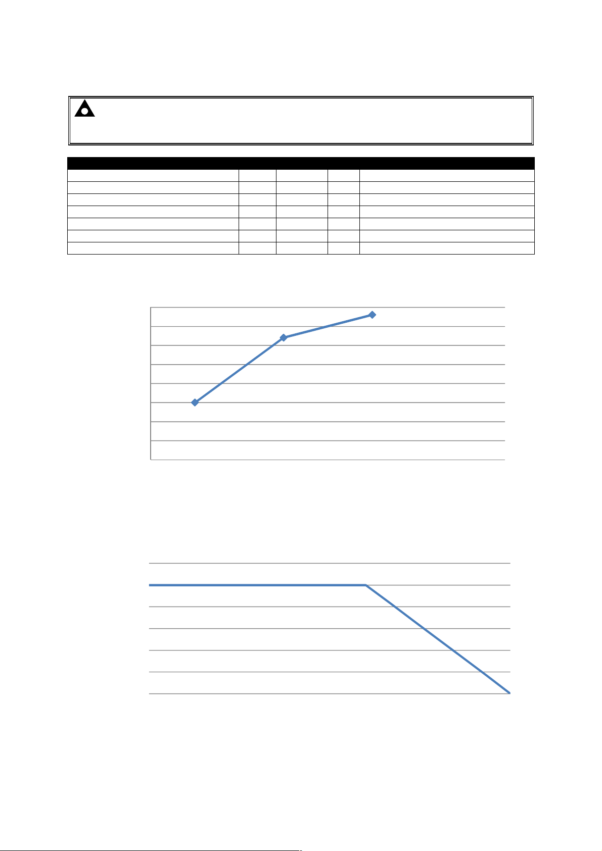
3.5.9 DSE9470 (MKII) 24V/12V 10A
NOTE: DSE9470 is factory configured to 24V 10A. If required, voltage and current levels
can be user configured via DSE Configuration Suite PC Software.
Part number 9470-001-00 is fixed at 24V 10A.
Output Voltage (24V DC Battery) 26.7V
Output Charging Current (A) 2A 10A 11A
Current limit threshold (A) 10A 11A
Recovery from current limit (A) 10A 11A
Full load AC input current (A) 2.3A At Vin=230V, Vo=28.8V, Io=10Amp
Full load AC input current (A) 4A At Vin=110V, Vo=28.8V, Io=10Amp
AC Input Inrush (10ms) current (A) 60A For 10ms
27V 29V
DSE9470 Efficiency Curve at 10A
0.925
0.92
0.915
0.91
0.905
0.9
Efficiency (%)
0.895
0.89
0.885
110 230 277
Input Voltage (V)
DSE9470 Smart Charger De-rating Curve
110V < Vin < 305V
12
10
8
6
4
Output Current (A)
2
0
-30 -20 -10 0 10 20 30 40 50 55 60 65 70 75 80 85
Ambient T emperature ºC
23
Page 26

DSE9470 Smart Charger De-rating Curve
6.0
5.0
4.0
3.0
2.0
Output Current (A)
1.0
0.0
-30 -20 -10 0 10 20 30 40 50 60 70 80 90 100
Specifications
95V < Vin < 110V
Ambient T emperature (ºC)
24
Page 27
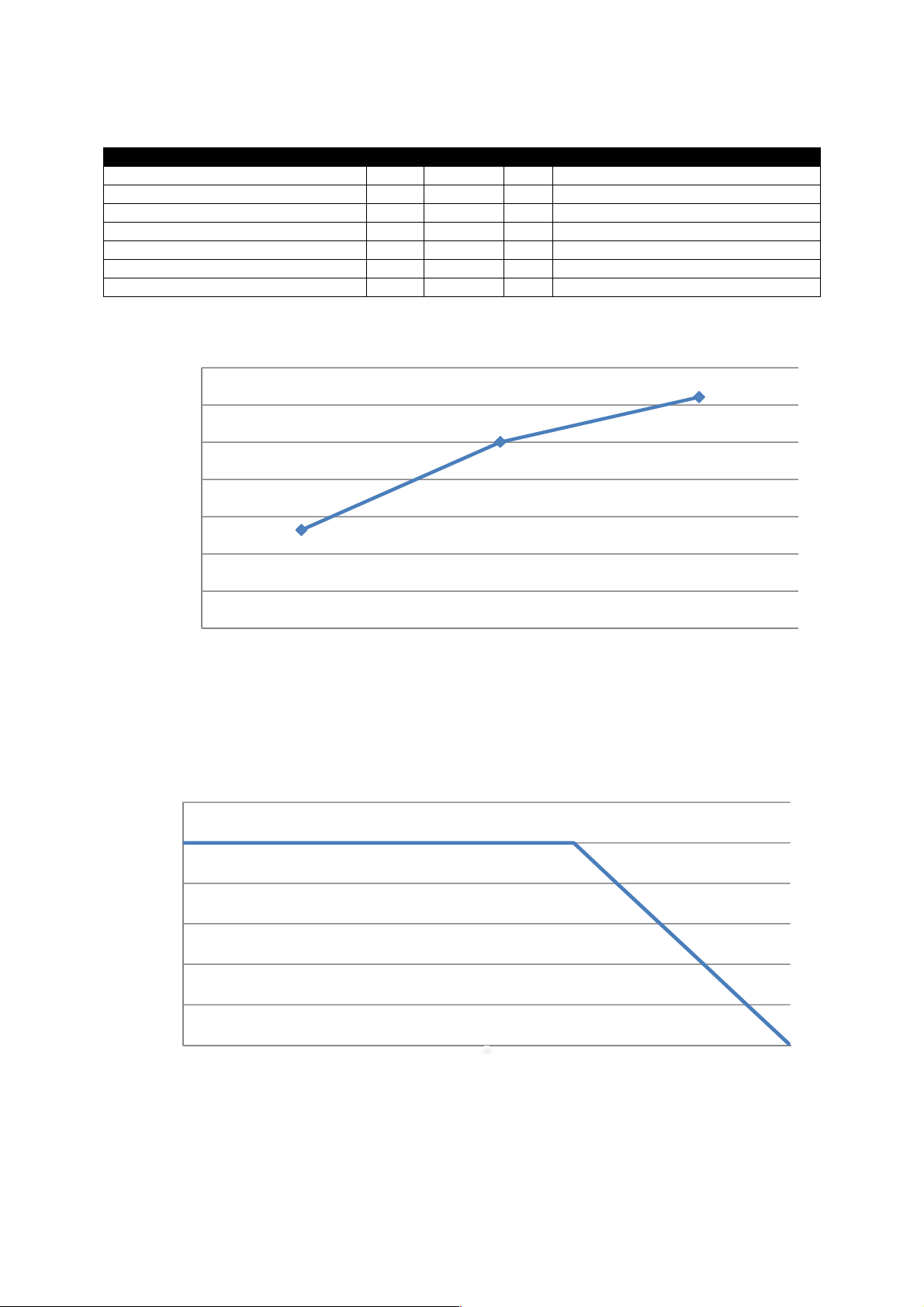
3.5.10 DSE9472 (MKII) 24V/12V 5A
Parameter
Min Nominal
Max Comments
110
230
277
Specifications
Output Voltage (24V DC Battery) 26.7V
Output Charging Current (A) 2A 5A 5.5A
Current limit threshold (A) 5A 5.5A
Recovery from current limit (A) 5A 5.5A
Full load AC input current (A) 1.2A At Vin=230V, Vo=28.8V, Io=5Amp
Full load AC input current (A) 2.2A At Vin=110V, Vo=28.8V, Io=5Amp
AC Input Inrush (10ms) current (A) 60A For 10ms
27V 29V
DSE9472 Efficiency Curve at 5A
93%
92%
92%
91%
91%
Efficiency (%)
90%
90%
89%
Input Voltage (V)
DSE9472 Smart Charger De-rating Curve
90V < Vin < 305V
6
5
4
3
2
Output Current (A)
1
0
-30 -20 -10 0 10 20 30 40 50 55 60 65 70 75 80
Ambient T emperature (°°°°C)
25
Page 28
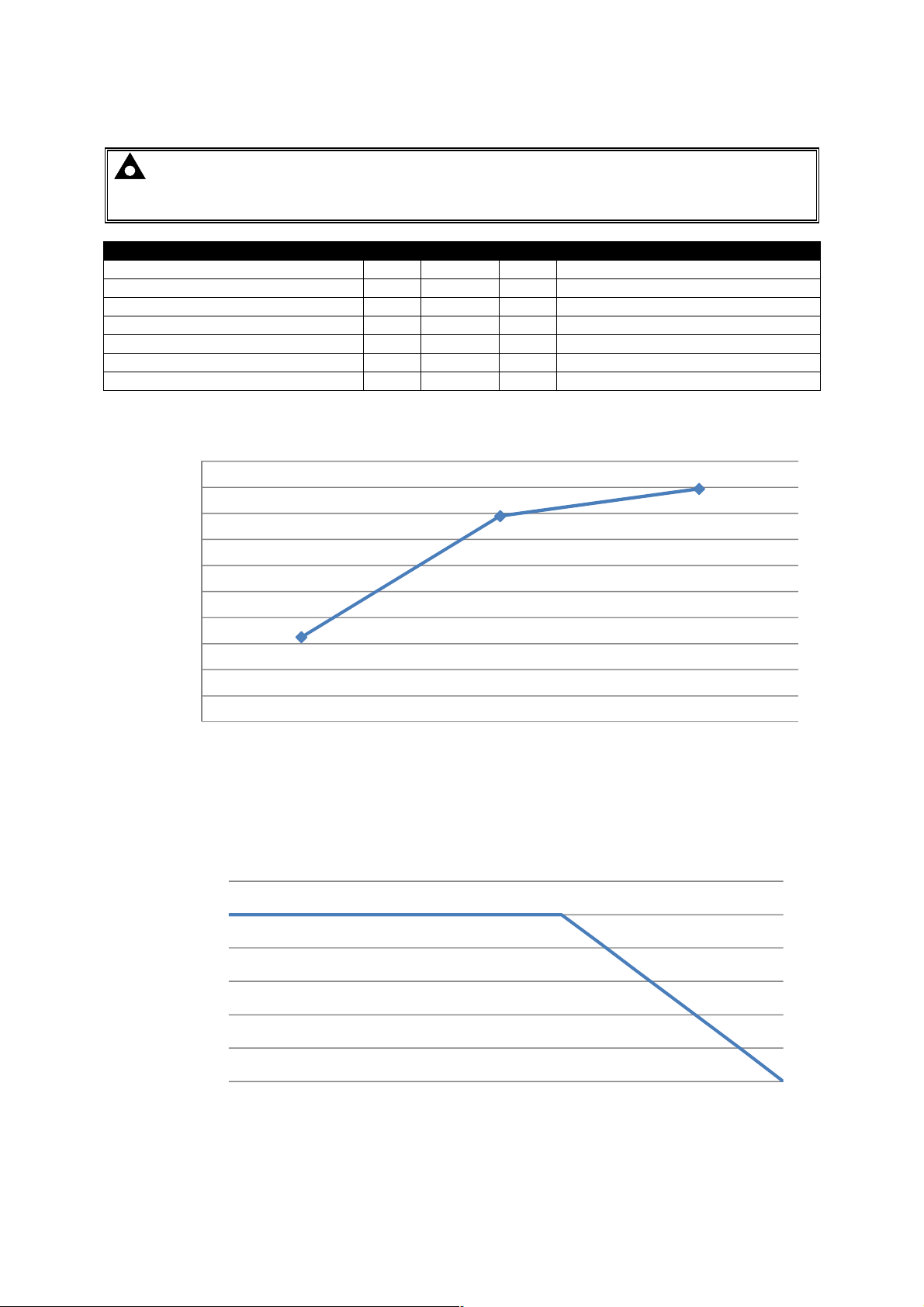
Specifications
Parameter
Min Nominal
Max Comments
-30-20-100102030405055606570758085
3.5.11 DSE9480 (MKII) 12V 10A
NOTE: DSE9480 is factory configured to 12V 10A. If required, voltage and currentl levels
can be user configured via DSE Configuration Suite PC Software.
Part number 9480-001-00 is fixed at 12V 10A.
Output Voltage (24V DC Battery) 13.4V 13.5V 14.5V
Output Charging Current (A) 2A 10A 11A
Current limit threshold (A) 10A 11A
Recovery from current limit (A) 10A 11A
Full load AC input current (A) 1.2A At Vin=230V, Vo=14.4V, Io=10Amp
Full load AC input current (A) 2.2A At Vin=110V, Vo=14.4V, Io=10Amp
AC Input Inrush (10ms) current (A) 60A For 10ms
DSE9480 Efficiency Curve at 10A
92%
91%
91%
90%
90%
89%
89%
88%
Efficiency (%)
88%
87%
87%
110 230 277
Input Voltage (V)
DSE9480 Smart Charger De-rating Curve
110V < Vin < 305V
12
10
8
6
4
Output Current (A)
2
0
Ambient T emperature ºC
26
Page 29

Specifications
DSE9470 Smart Charger De-rating Curve
95V < Vin < 110V
6.0
5.0
4.0
3.0
2.0
Output Current (A)
1.0
0.0
-30 -20 -10 0 10 20 30 40 50 60 70 80 90 100
Ambient T emperature (ºC)
27
Page 30
Specifications
Parameter
Min Nominal
Max Comments
110
230
277
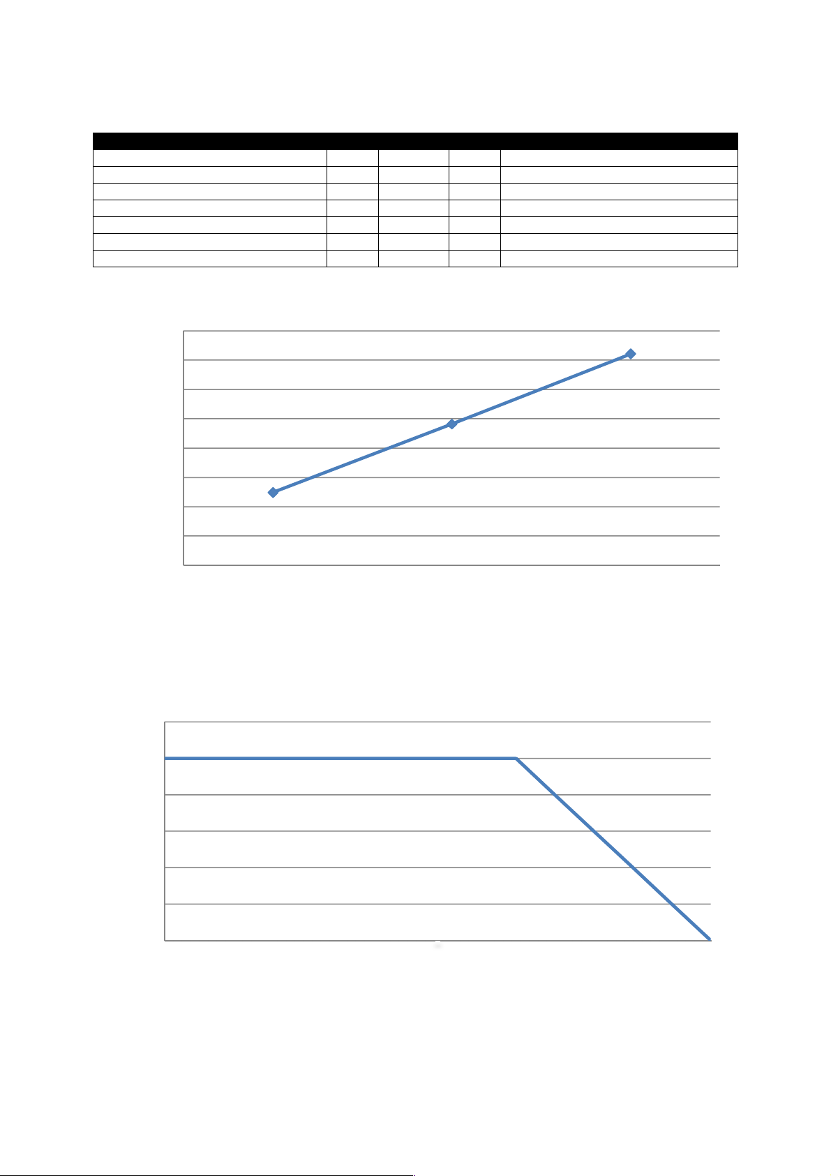
3.5.12 DSE9481 (MKII) 12V 5A
Output Voltage (24V DC Battery) 13.4V 13.5V 14.5V
Output Charging Current (A) 2A 5A 5.5A
Current limit threshold (A) 5A 5.5A
Recovery from current limit (A) 5A
Full load AC input current (A) 0.5A At Vin=230V, Vo=14.4V, Io=5Amp
Full load AC input current (A) 1.1A At Vin=110V, Vo=14.4V, Io=5Amp
AC Input Inrush (10ms) current (A) 60A For 10ms
DSE9481 Efficiency Curve at 5A
93%
92%
92%
91%
91%
90%
Efficiency (%)
90%
89%
89%
Input Voltage (V)
DSE9481 Smart Charger De-rating Curve
90V < Vin < 305V
6
5
4
3
2
Output Current (A)
1
0
-30 -20 -10 0 10 20 30 40 50 55 60 65 70 75 80
Ambient T emperature (°°°°C)
28
Page 31
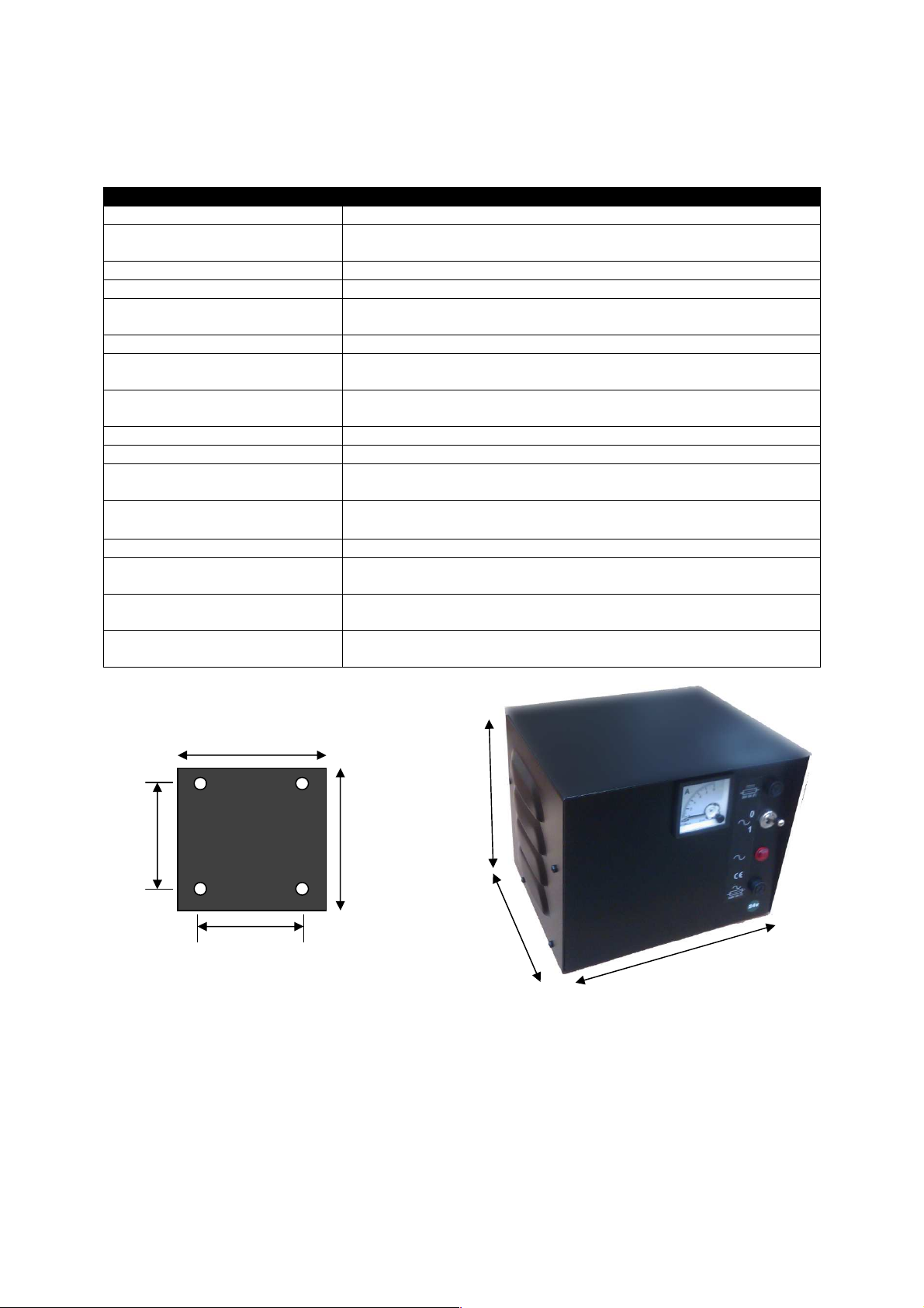
Specifications
Parameter
Comment
Mounting Plate (supplied)
Enclosure
3.6 DIMENSIONS AND MOUNTING
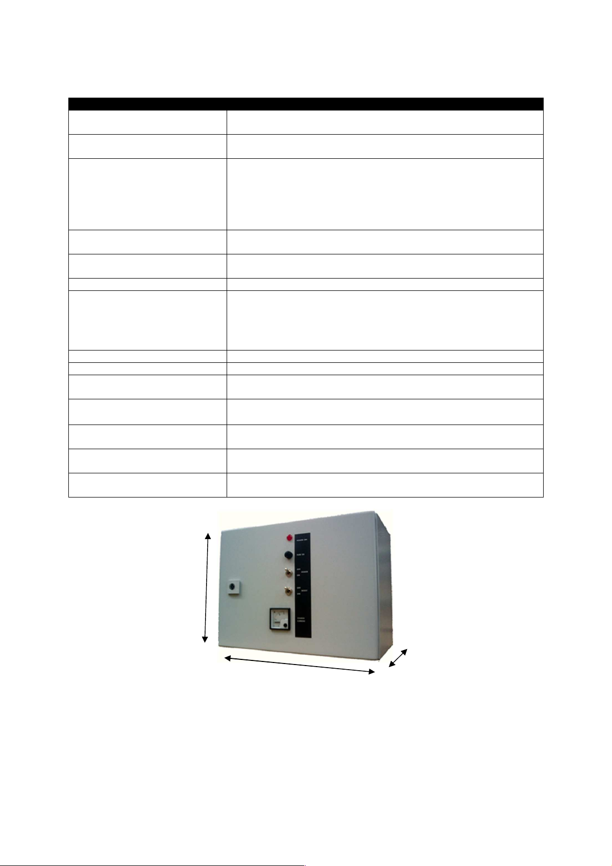
3.6.1 DSE907 12V 10A INDUSTRIAL BATTERY CHARGER
Cabinet type Custom cabinet
Overall size
(see below for diagram)
Material: Sheet steel enclosure of all-round solid construction
Surface finish: Powder-coated black
Protection category:
Weight 5.6kg
Mounting type
Mounting holes
Input voltage (nominal) 110V-277V
Input voltage (absolute range) 90V-305V
Charge failure relay rating
Operating Temperature
Controls AC Power on/off
Indication
AC Fuse
DC Fuse
200mm x 185mm x 170mm (7.9“ x 7.3“ x 6.7“)
Add 20mm (0.79”) to depth when using supplied mounting plate.
IP20
NEMA 1
Wall mounting using supplied wall bracket
Wall bracket add 20mm (0.79”) to the depth of the enclosure
Diameter 5mm (0.2”)
130mm (5.1) centres
3A DC resistive
30V maximum
-30°C to 55°C
(-22°F to 131°F)
0A-10A DC ammeter
Power on Red neon indicator
Fuse holder mounted onto front panel.
Accepts 2A anti-surge fuse (20mm x 5mm fuse)
Fuse holder mounted onto front panel.
Accepts 5A anti-surge fuse (20mm x 5mm fuse)
165mm
185mm
130mm
130mm
170mm
170mm
add 20mm when
fitting supplied wall
bracket
Dimensions in mm
200mm
29
Page 32
Specifications
Parameter
Comment
3.6.2 DSE908 12V & 24V 10A CABINET MOUNTED BATTERY CHARGER
Cabinet type
Overall size
AE1031.500 by Rittal –
Rittal website www.rittal.de / www.rittal.co.uk
380mm x 300mm x 210mm
(15.0.” x 11.8”x 8.3”)
Sheet steel enclosure of all-round solid construction
Single door, right hand hinge with one cam lock
Material:
Foamed-in door seal
1 foamed in gland plate in the enclosure base
(Gland plate supplied blank, ready for customer drilling as
required).
Surface finish:
Protection category:
Dipcoat primed, powder-coated on the outside in textured RAL
7035
IP20
NEMA 1
Weight 15kg
Wall mounting. Can be mounted by customer drilled holes or by
using Rittal mounting brackets, suitable for Rittal cabinet type
Mounting type
AE1030.500 – For example Rittal Part number 2508.010 (Pack of
4)
Rittal website www.rittal.de / www.rittal.co.uk
Input voltage (nominal) 110V-277V
Input voltage (absolute range) 90V-305V
Charge failure relay rating
Operating Temperature
Controls
Indication
AC Fuse
3A DC resistive
30V maximum
-30°C to 55°C
(-22°F to 131°F)
AC Power on/off
Boost charge on/off
0A-15A DC ammeter
Power on Red neon indicator
Fuse holder mounted onto front panel.
Accepts 2A anti-surge fuse (20mm x 5mm fuse)
300mm
380mm
Dimensions in mm
30
210mm
Page 33
Specifications
Parameter
Comment
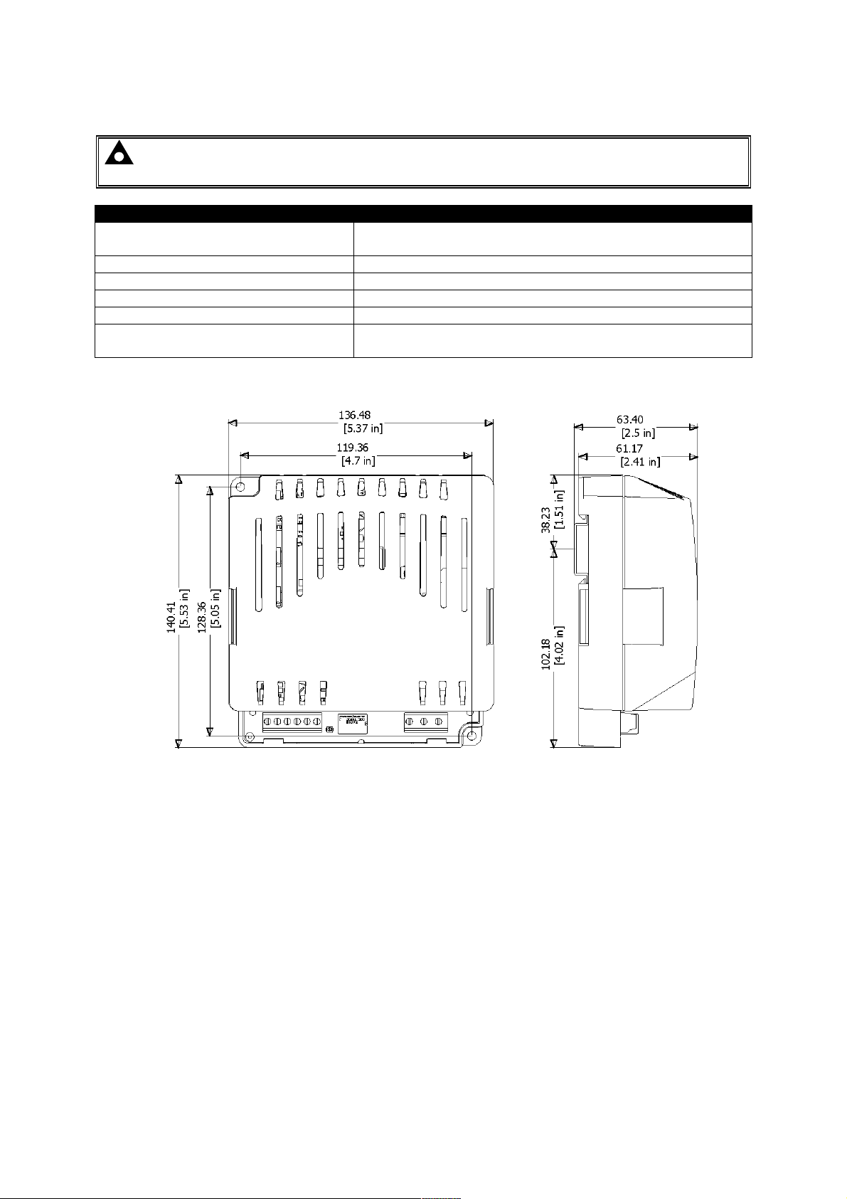
3.6.3 DSE9130 12V 5A
NOTE: This battery charger is designed to be mounted with the base to a vertical surface
with the terminal strips at the bottom.
Overall size
Weight 0.5kg
Mounting type DIN rail or chassis mounting
Din rail type EN 50022 35mm type only
Mounting holes Suitable for M4
Mounting hole centres
136.48mm x 140.41mm x 63.40mm
(5.37” x 5.53” x 2.5”)
119.36mm x 128.36mm
(4.7” x 5.05”)
Dimensions in mm unless stated
31
Page 34
Specifications
Parameter
Comment
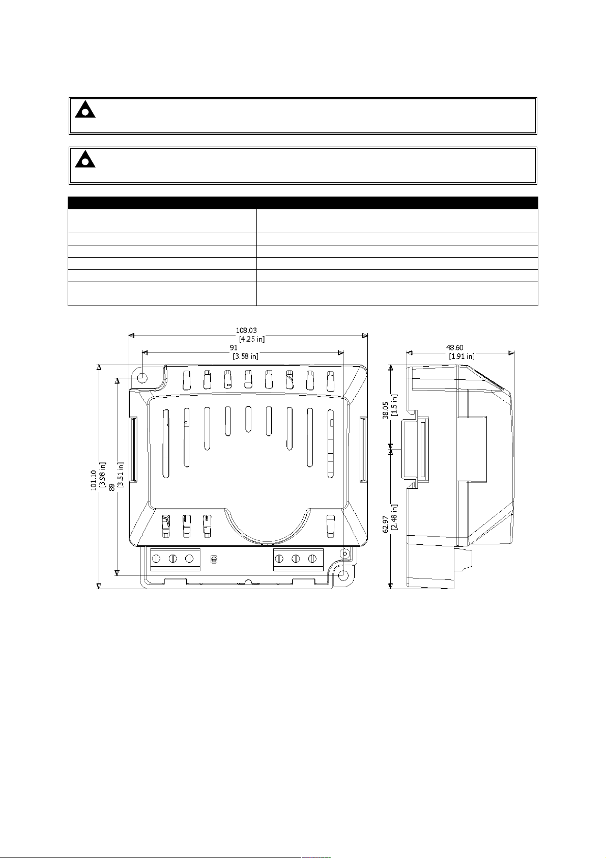
3.6.4 DSE9150 12V 2A
NOTE: This device is no longer available, replaced by DSE9150 12V 3A. See overleaf for
updated specifications.
NOTE: This battery charger is designed to be mounted with the base to a vertical surface
with the terminal strips at the bottom.
Overall size
Weight 0.16kg
Mounting type DIN rail or chassis mounting
Din rail type EN 50022 35mm type only
Mounting holes Suitable for M4
Mounting hole centres
108.03mm x 101.10mm x 48.6mm
(4.25” x 3.98” x 1.91”)
91mm x 89mm
(4.25” x 3.51”)
Dimensions in mm unless stated
32
Page 35
Specifications
Parameter
Comment
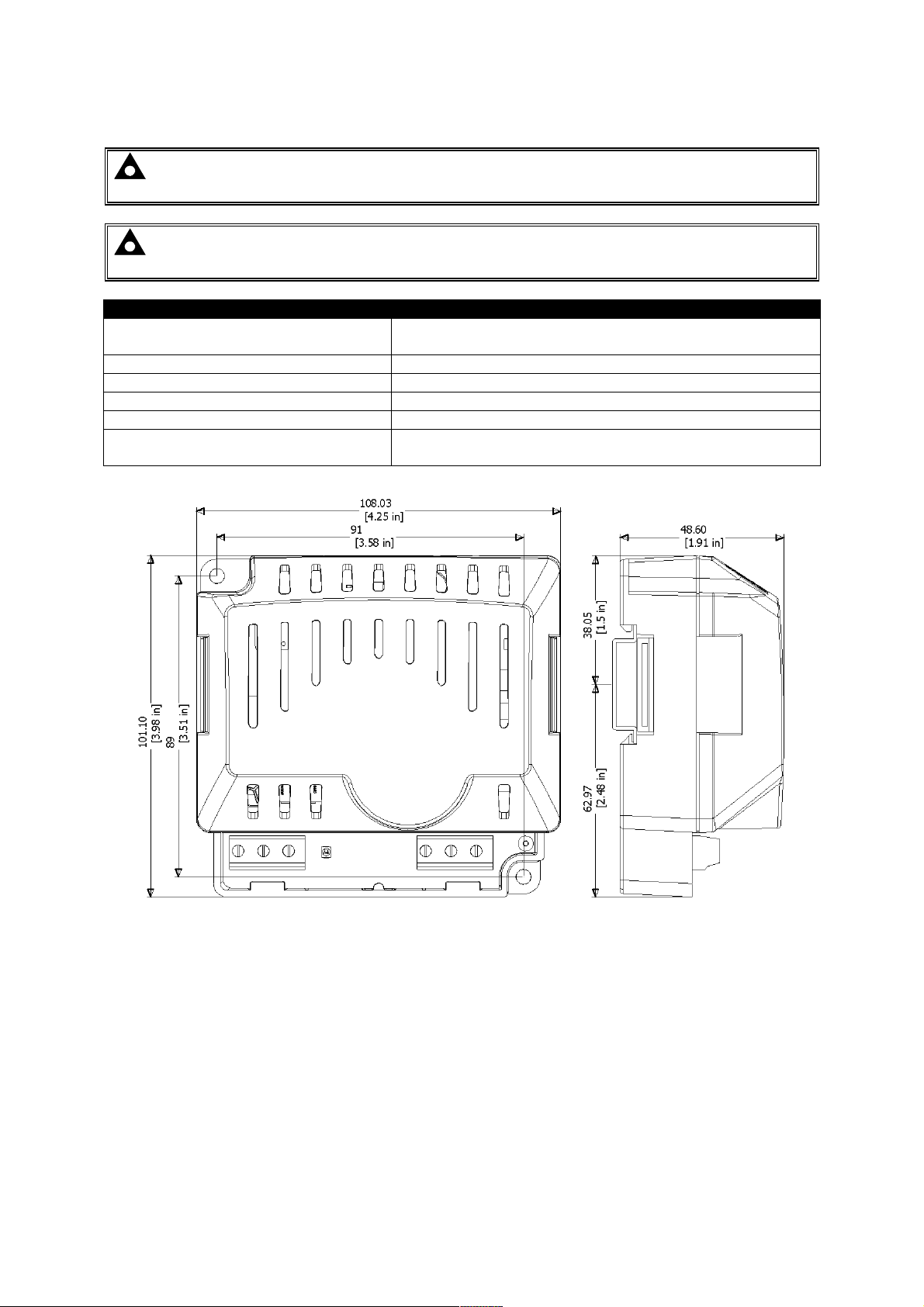
3.6.5 DSE9150 12V 3A
NOTE: This device has replaced DSE9150 12V 2A. See previous page for specifications of
the earlier model.
NOTE: This battery charger is designed to be mounted with the base to a vertical surface
with the terminal strips at the bottom.
Overall size
Weight 0.16kg
Mounting type DIN rail or chassis mounting
Din rail type EN 50022 35mm type only
Mounting holes Suitable for M4
Mounting hole centres
108.03mm x 101.10mm x 48.6mm
(4.25” x 3.98” x 1.91”)
91mm x 89mm
(4.25” x 3.51”)
Dimensions in mm unless stated
33
Page 36
Specifications
Parameter
Comment
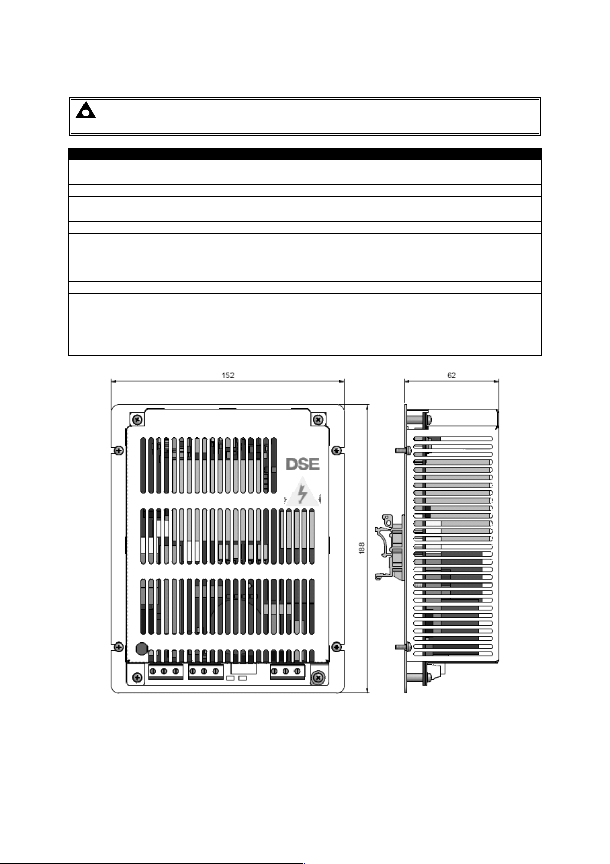
3.6.6 DSE9140 12V 10A
NOTE: This battery charger is designed to be mounted with the base to a vertical surface
with the terminal strips at the bottom.
Overall size
152mm x 188mm x 2.44mm
(6” x 7.4”x 2.44”)
Weight 0.75kg
Mounting type DIN rail or chassis mounting
Din rail type EN 50022 35mm type only
Mounting holes Suitable for M4
142mm x 128mm
Mounting hole centres
(5.59” x 5.0”)
30mm (1.18”) from top and bottom edges
5mm (1.97”) from left and right edges.
Input voltage (nominal) 110V-277V
Input voltage (absolute range) 90V-305V
Charge failure relay rating
Operating Temperature
3A DC resistive
30V maximum
-30°C to 55°C
(-22°F to 131°F)
6 in
2.44 in
7.4 in
Dimensions in mm unless stated
34
Page 37
Specifications
Parameter
Comment
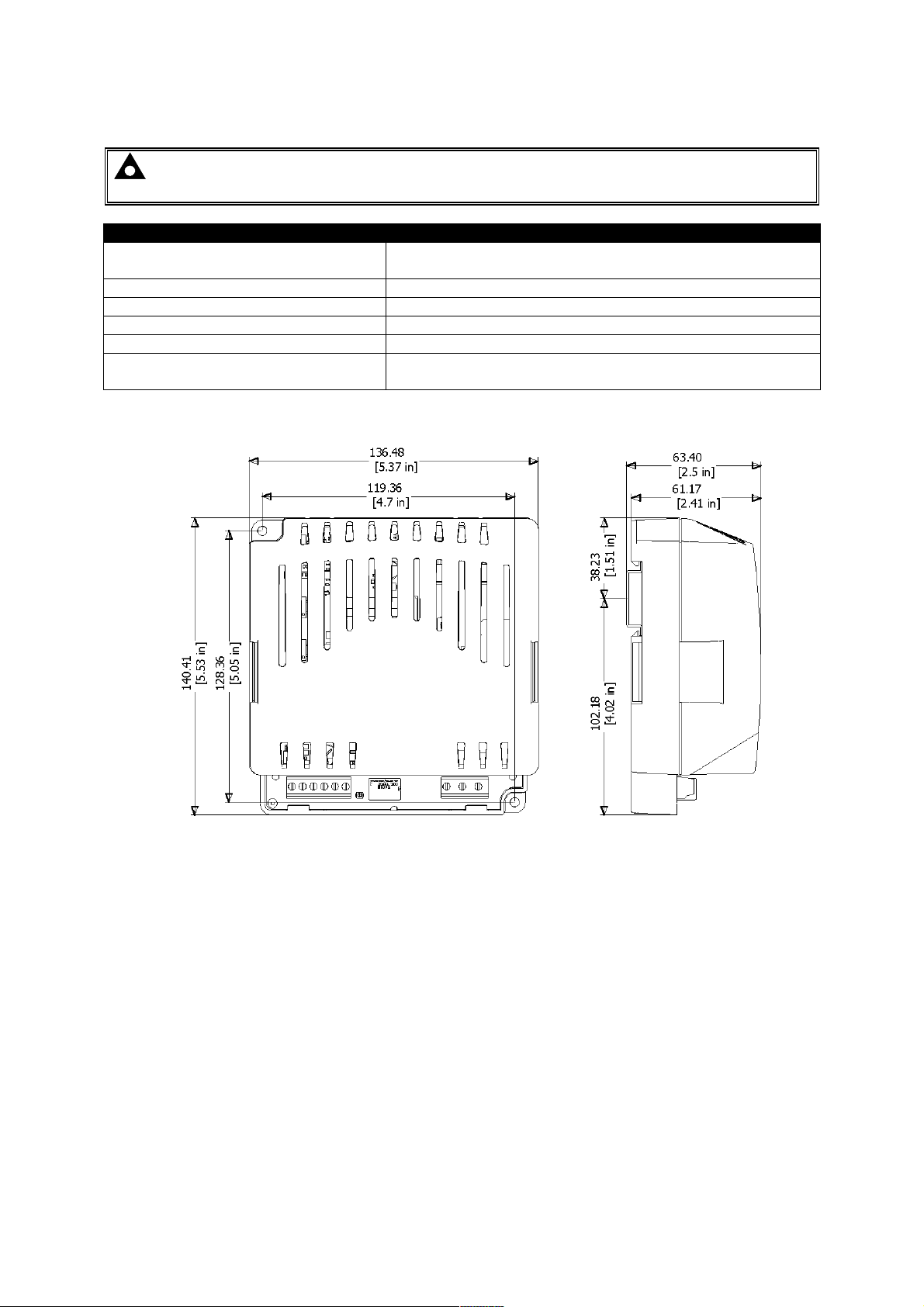
3.6.7 DSE9155 30V 2A
NOTE: This battery charger is designed to be mounted with the base to a vertical surface
with the terminal strips at the bottom.
Overall size
Weight 0.5kg
Mounting type DIN rail or chassis mounting
Din rail type EN 50022 35mm type only
Mounting holes Suitable for M4
Mounting hole centres
136.48mm x 140.41mm x 63.40mm
(5.37” x 5.53” x 2.5”)
119.36mm x 128.36mm
4.7” x 5.05”
Dimensions in mm unless stated
35
Page 38
Specifications
Parameter
Comment
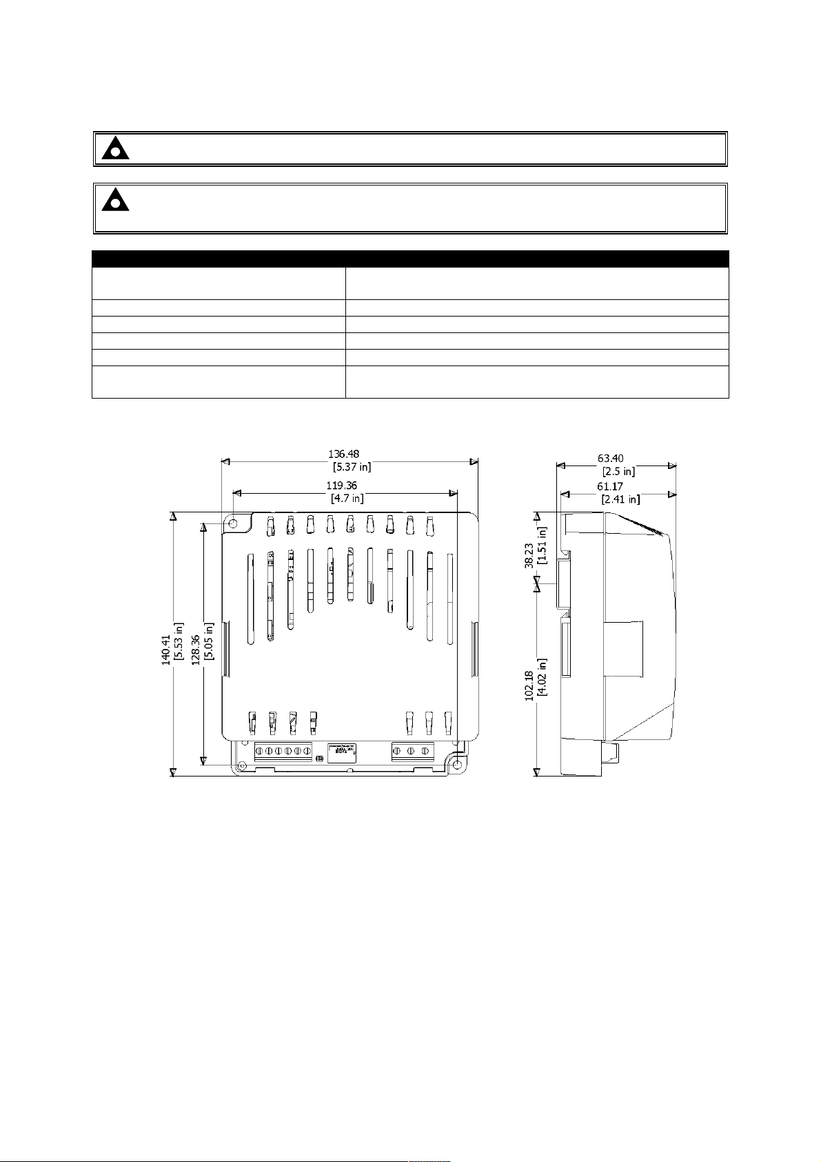
3.6.8 DSE9250 24V 3.7A
NOTE: - This battery charger is now obsolete, details provided for information only.
NOTE: This battery charger is designed to be mounted with the base to a vertical surface
with the terminal strips at the bottom.
Overall size
Weight 0.5kg
Mounting type DIN rail or chassis mounting
Din rail type EN 50022 35mm type only
Mounting holes Suitable for M4
Mounting hole centres
136.48mm x 140.41mm x 63.40mm
(5.37” x 5.53” x 2.5”)
119.36mm x 128.36mm
(4.7” x 5.05”)
Dimensions in mm unless stated
36
Page 39
Specifications
Parameter
Comment
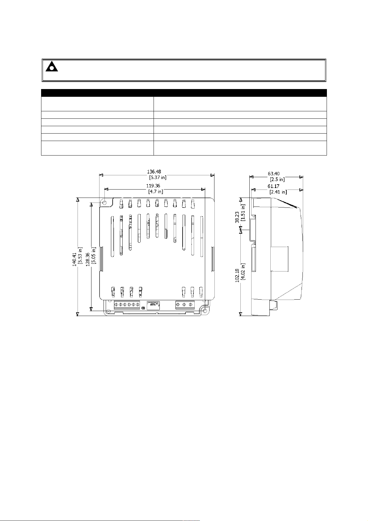
3.6.9 DSE9255 24V 5A
NOTE: This battery charger is designed to be mounted with the base to a vertical surface
with the terminal strips at the bottom.
Overall size 136.48mm x 140.41mm x 63.40mm
(5.37” x 5.53” x 2.5”)
Weight 0.5kg
Mounting type DIN rail or chassis mounting
Din rail type EN 50022 35mm type only
Mounting holes Suitable for M4
Mounting hole centres 119.36mm x 128.36mm
(4.7” x 5.05”)
Dimensions in mm unless stated
37
Page 40
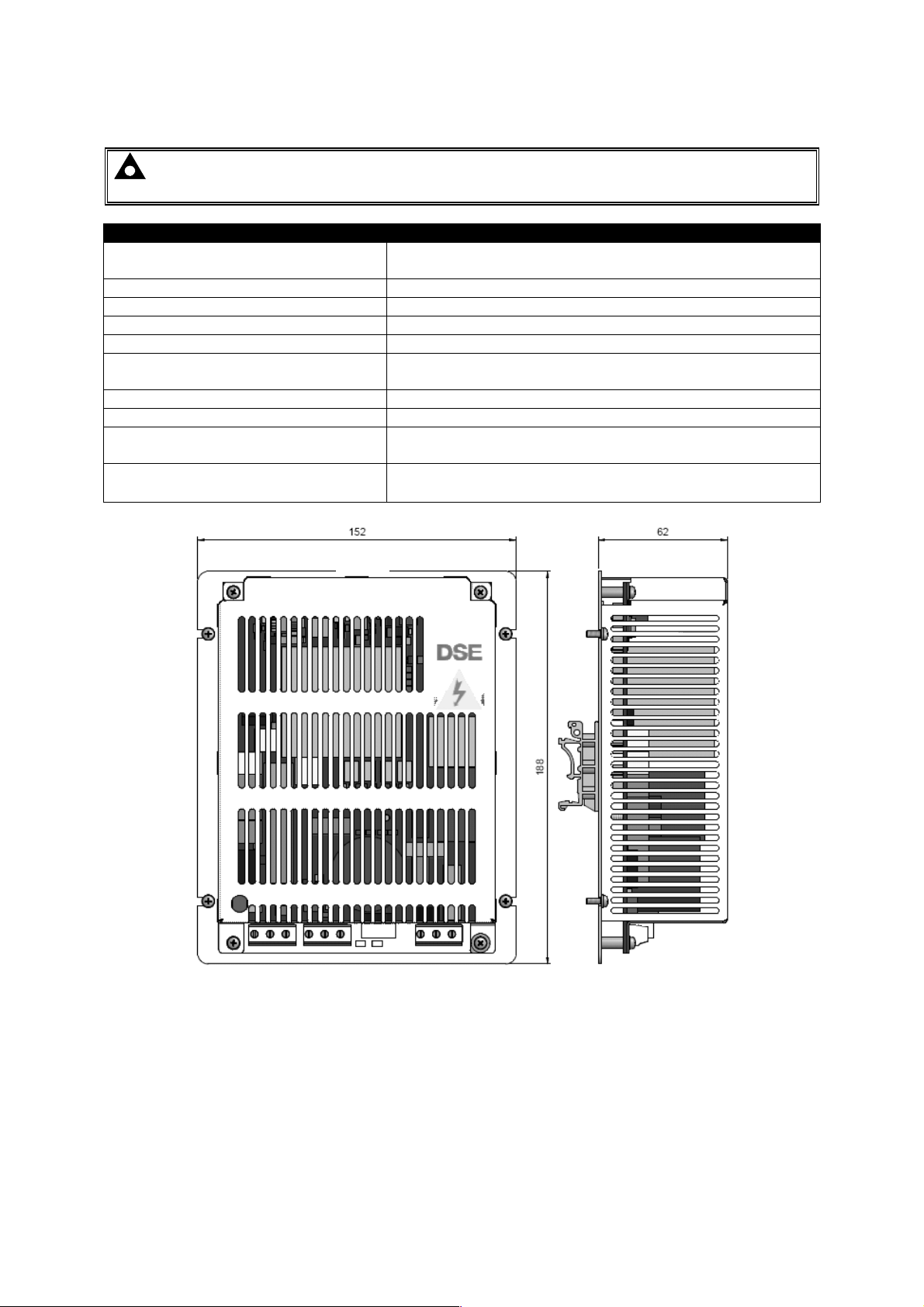
Specifications
Parameter
Comment
3.6.10 DSE9260 24V 10A
NOTE: This battery charger is designed to be mounted with the base to a vertical surface
with the terminal strips at the bottom.
Overall size
152mm x 188mm x 2.44mm
(6.0” x 7.4”x 2.44”)
Weight 0.85kg
Mounting type DIN rail or chassis mounting
Din rail type EN 50022 35mm type only
Mounting holes Suitable for M4
Mounting hole centres
142mm x 128mm
(5.59” x 5.0”)
Input voltage (nominal) 110V-277V
Input voltage (absolute range) 90V-305V
Charge failure relay rating
Operating Temperature
3A DC resistive
30V maximum
-30°C to 55°C
(-22°F to 131°F)
6 in
2.44 in
7.4 in
Dimensions in mm unless stated
38
Page 41
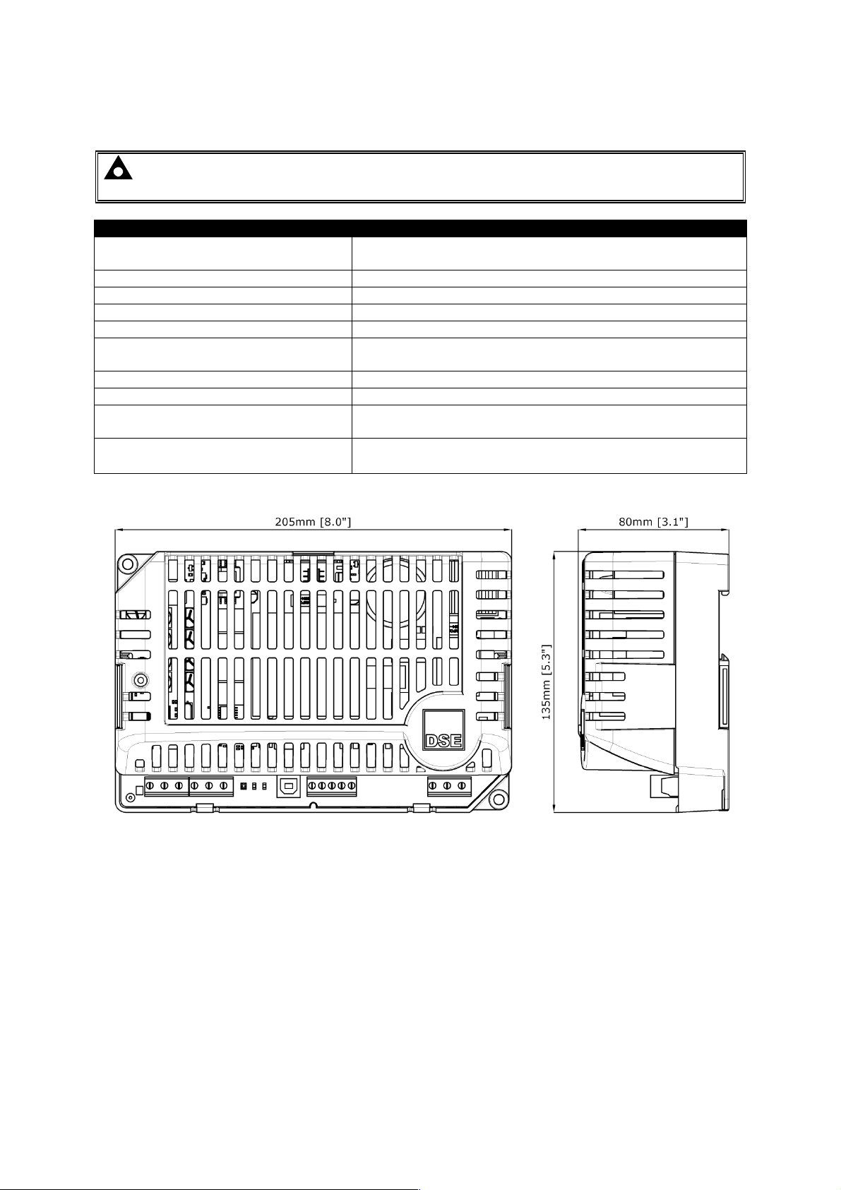
Specifications
Parameter
Comment
3.6.11 DSE9470 (MKII) 24V/12V 10A
NOTE: This battery charger is designed to be mounted with the base to a vertical surface
with the terminal strips at the bottom.
Overall size(mm)
Weight 0.78kg
Mounting type DIN rail or chassis mounting
Din rail type EN 50022 35mm type only
Mounting holes Suitable for M4
Mounting hole centres
Input voltage (nominal) 110V-277V
Input voltage (absolute range) 95V-305V
Charge failure relay rating
Operating Temperature
205mm x 135mm x 80mm
(8.0” x 5.3” x 3.1”)
190mm x 120mm
(7.5” x 4.7”)
3A DC resistive
30V maximum
-30°C to 85°C with de rating
(-22°F to 185°F with de rating)
39
Page 42
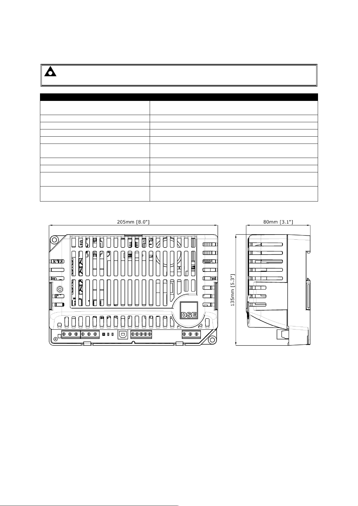
Specifications
Parameter
Comment
3.6.12 DSE9472 (MKII) 24V/12V 5A
NOTE: This battery charger is designed to be mounted with the base to a vertical surface
with the terminal strips at the bottom.
Overall size(mm)
Weight 0.7kg
Mounting type DIN rail or chassis mounting
Din rail type EN 50022 35mm type only
Mounting holes Suitable for M4
Mounting hole centres
Input voltage (nominal) 110V-277V
Input voltage (absolute range) 95V-305V
Charge failure relay rating
Operating Temperature
205mm x 135mm x 80mm
(8.0” x 5.3” x 3.1”)
190mm x 120mm
(7.5” x 4.7”)
3A DC resistive
30V maximum
-30°C to 85°C with de rating
(-22°F to 185°F with de rating)
40
Page 43
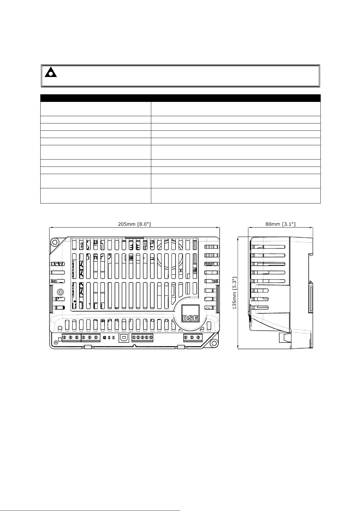
Specifications
Parameter
Comment
3.6.13 DSE9480 (MKII) 12V/24V 10A
NOTE: This battery charger is designed to be mounted with the base to a vertical surface
with the terminal strips at the bottom.
Overall size(mm)
Weight 0.7kg
Mounting type DIN rail or chassis mounting
Din rail type EN 50022 35mm type only
Mounting holes Suitable for M4
Mounting hole centres
Input voltage (nominal) 110V-277V
Input voltage (absolute range) 95V-305V
Charge failure relay rating
Operating Temperature
205mm x 135mm x 80mm
(8.0” x 5.3” x 3.1”)
190mm x 120mm
(7.5” x 4.7”)
3A DC resistive
30V maximum
-30°C to 85°C with de rating
(-22°F to 185°F with de rating)
41
Page 44
Specifications
Parameter
Comment
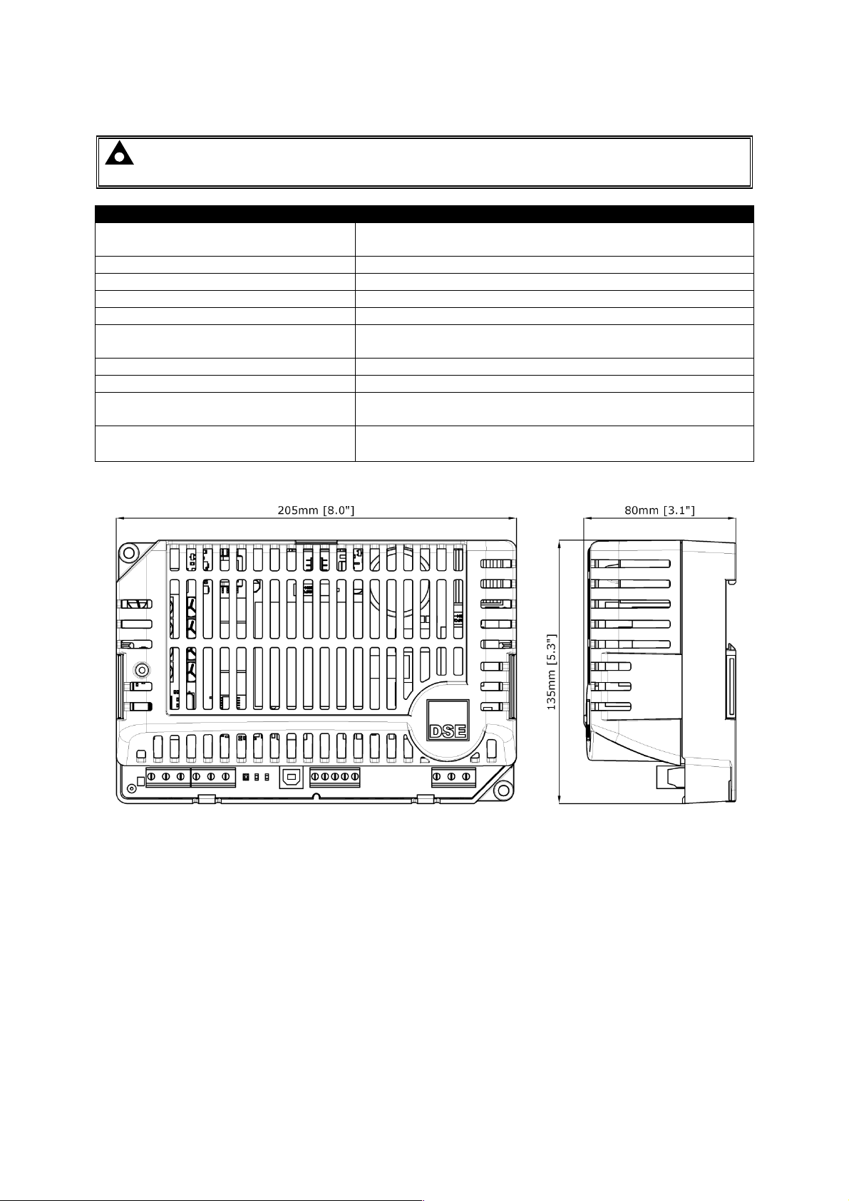
3.6.14 DSE9481 (MKII) 12V/24V 5A
NOTE: This battery charger is designed to be mounted with the base to a vertical surface
with the terminal strips at the bottom.
Overall size(mm)
Weight 0.7kg
Mounting type DIN rail or chassis mounting
Din rail type EN 50022 35mm type only
Mounting holes Suitable for M4
Mounting hole centres
Input voltage (nominal) 110V-277V
Input voltage (absolute range) 95V-305V
Charge failure relay rating
Operating Temperature
205mm x 135mm x 80mm
(8.0” x 5.3” x 3.1”)
190mm x 120mm
(7.5” x 4.7”)
3A DC resistive
30V maximum
-30°C to 85°C with de rating
(-22°F to 185°F with de rating)
42
Page 45

3.7 APPLICABLE STANDARDS
Specifications
BS 4884-1
BS 4884-2
BS 4884-3
BS EN 60068-2-1
(Minimum temperature)
BS EN 60068-2-2
(Maximum temperature)
BS EN 60950
BS EN 61000-6-2
This document conforms to BS4884-1 1992 Specification for
presentation of essential information.
This document conforms to BS4884-2 1993 Guide to content.
This document conforms to BS4884-3 1993 Guide to presentation.
-30°C (-22°F)
+55°C (131°F)
Safety of information technology equipment, including electrical
business equipment.
EMC Generic Immunity Standard (Industrial).
BS EN 61000-6-4
EMC Generic Emission Standard (Industrial).
IP20
BS EN 60529
(Degrees of protection
provided by enclosures)
Protected against penetration by solid objects with a diameter of more
than 12 mm. Fingers or similar objects prevented from approach.
No protection against water
Enclosure type 1
UL508
NEMA rating
Provides a degree of protection against contact with the enclosure
equipment and against a limited amount of falling dirt
UK WEEE
REGULATIONS
In line with our policy of continual development, Deep Sea Electronics, reserve the right to change spec ific ation with out notic e.
Producer Registration Number WEE/BE0052TQ
43
Page 46
Installation
Parameter
Comment
Recommended AC fuse
230V AC Input
110V AC Input
4 INSTALLATION
NOTE: The DSE9000 series battery charger should only be used to charge one battery
bank at a time. It is not recommended to parallel batteries as the tolerance of the batteries
leads to imbalance in their charging.
The DSE9000 battery charger is designed to be mounted within a control panel, on the panel DIN rail
utilising the integral mounts or on a chassis utilising the mounting holes. For dimension and mounting
details, see the section entitled Specification, Dimensions elsewhere in this document.
The DSE9000 battery charger is fit-and-forget. It can be permanently connected to the supply and the
load, with no requirement to disable the charger during times of heavy load (such as engine cranking)
or when the generator is running (even when a DC charging alternator is fitted).
4.1 BATTERY SUITABILITY
The standard charger is factory set by DSE to suit Lead Acid batteries but can be adjusted at the time
of ordering to suit other battery types. Care should be taken to ensure the batteries connected to the
charger are of the correct ‘technology’ to suit the setting of the charger.
For details of other supported battery types and float voltages see the section entitled Specifications,
Part Numbering elsewhere in this document.
4.2 USER CONNECTIONS
Connection type Screw terminal, rising clamp, no internal spring
Min cable size 0.5mm² (AWG 20)
Max cable size 2.5mm² (AWG 14)
DSE9130 12V 5A charger
DSE9140 12V 10A charger
DSE9150 12V 2A charger
DSE9150 12V 3A charger
DSE9155 30V 2A charger
DSE9250 24V 3.7A charger
DSE9260 24V 10A charger
DSE9255 24V 5A charger
DSE9470 24V/12V 10A charger
DSE9480 12V/24V 10A charger
DSE9481 12V 5A charger
DSE9472 24V 5A charger
1.0A anti-surge
2.0A anti-surge
1.0A anti-surge
1.5A anti-surge
1.0A anti-surge
1.0A anti-surge
3.5A anti-surge
2.0A anti-surge
3.5A anti-surge
2.0A anti-surge
1.0A antisurge
2.0A antisurge
2.0A anti-surge
3.5A anti-surge
1.5A anti-surge
2.0A anti-surge
2.5A anti-surge
2.5A anti-surge
6.3A anti-surge
3.5A anti-surge
6.3A anti-surge
3.5A anti-surge
2.5A anti-surge
3.5A anti-surge
NOTE: Where DSE9470 / DSE9480 current rating has been user configured below 10A, an
appropriate fuse size must be selected to match the lower maximum output current.
44
Page 47
Installation
Terminal
Function
Recommended S
ize Comments
Terminal
Function
Recommended S
ize
Terminal
Function
Recommended S
ize Comments
Terminal
Function
Recommended S
ize
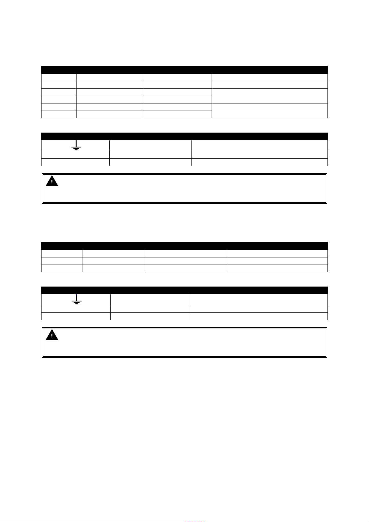
4.2.1 DSE9130, DSE9140, DSE9250, DSE9255 & DSE9260
Connector A
-OP Load negative 1mm² (AWG 16) Battery negative terminal
+OP Load Positive 1mm² (AWG 16) Battery positive terminal
BOOST Boost mode 0.5 mm² (AWG 22)
BOOST Boost mode 0.5 mm² (AWG 22)
CF Charge failure relay 0.5 mm² (AWG 22)
CF Charge failure relay 0.5 mm² (AWG 22)
Connector B
Earth 1mm² (AWG 16)
N AC Neutral 1mm² (AWG 16)
L AC Live 1mm² (AWG 16)
CAUTION: Ensure Earth Terminal is connected to Battery negative (for negative earth
systems) or Battery positive (for positive earth systems)
Where no system earth exists, Earth Terminal must be connected to battery negative
Connect together for boost operation
Closes under charge fail conditions
4.2.2 DSE9150
Connector A
NC Not Connected Do not connect
-OP Load negative 1mm² (AWG 16) Battery negative terminal
+OP Load Positive 1mm² (AWG 16) Battery positive terminal
Connector B
Earth 1mm² (AWG 18)
N AC Neutral 1mm² (AWG 18)
L AC Live 1mm² (AWG 18)
CAUTION: Ensure Earth Terminal is connected to Battery negative (for negative earth
systems) or Battery positive (for positive earth systems)
Where no system earth exists, Earth Terminal must be connected to battery negative
45
Page 48
Installation
Terminal
Function
Recommended size
Comments
Terminal
Function
Recommended S
ize
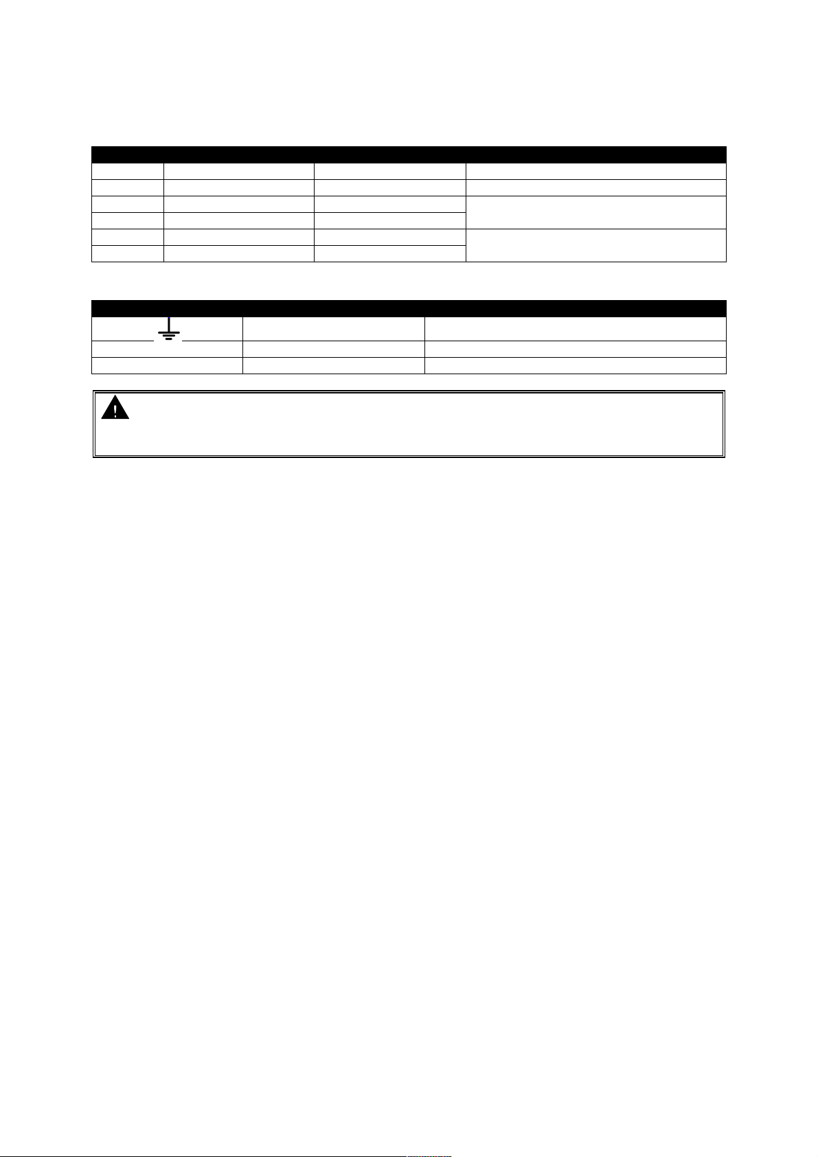
4.2.3 DSE9155
Connector A
-OP Load negative 1mm² (AWG 16) Battery negative terminal
+OP Load Positive 1mm² (AWG 16) Battery positive terminal
BOOST N/A 0.5 mm² (AWG 22)
BOOST N/A 0.5 mm² (AWG 22)
CF Charge failure relay 0.5 mm² (AWG 22)
CF Charge failure relay 0.5 mm² (AWG 22)
Boost not avaialble on DSE9155
Closes under charge fail conditions
Connector B
Earth 1mm² (AWG 16)
N AC Neutral 1mm² (AWG 16)
L AC Live 1mm² (AWG 16)
CAUTION: Ensure Earth Terminal is connected to Battery negative (for negative earth
systems) or Battery positive (for positive earth systems).
Where no system earth exists, Earth Terminal must be connected to battery negative.
46
Page 49
Installation
Terminal
Function
Recommended size
Comments
Terminal
Function
Recommended size
Comments
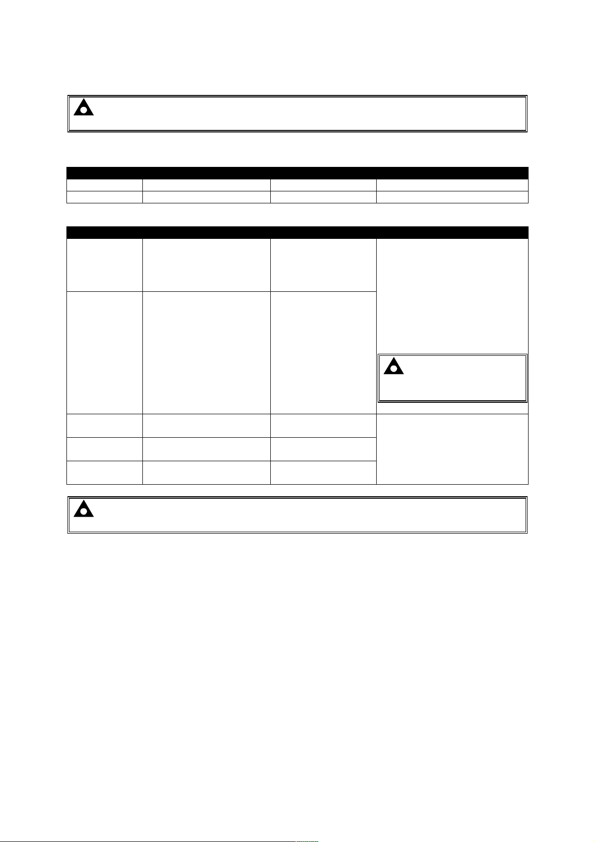
4.2.4 DSE9470 MKII, DSE9472 MKII, DSE9480 MKII, DSE9481 MKII
NOTE: For obsolete parts 9470-001-00 and 9480-001-00 contact DSE Technical Support for
connection details.
Connector A
-OP Load negative 1mm² (AWG 16) Battery negative terminal
+OP Load Positive 1mm² (AWG 16) Battery positive terminal
Connector B
Connect the terminals together
LK1 Configurable Input 1mm² (AWG 16)
LK1
NC
COM
NO
Configurable Input (0V) 1mm² (AWG 16)
Normally Closed Contact
of the Charge failure relay
Charge failure relay
Contact Common
Normally Open Contact of
the Charge failure relay
0.5 mm² (AWG 22)
0.5 mm² (AWG 22)
0.5 mm² (AWG 22)
to activate the input.
The Factory Setting for the
digital input provides a
selection of 12V / 24V
operation.
Customer configurable using
DSE Configuration Suite PC
Software.
NOTE: Digital Input Not
Fitted to 9470-001-00 and
9480-001-00.
Changes State Under Charge
Fail Conditions
NOTE: For further details of PC Configuration, you are referred to DSE Publication: 057-
159 DSE9400 Series Battery Charger Configuration Suite Manual.
47
Page 50
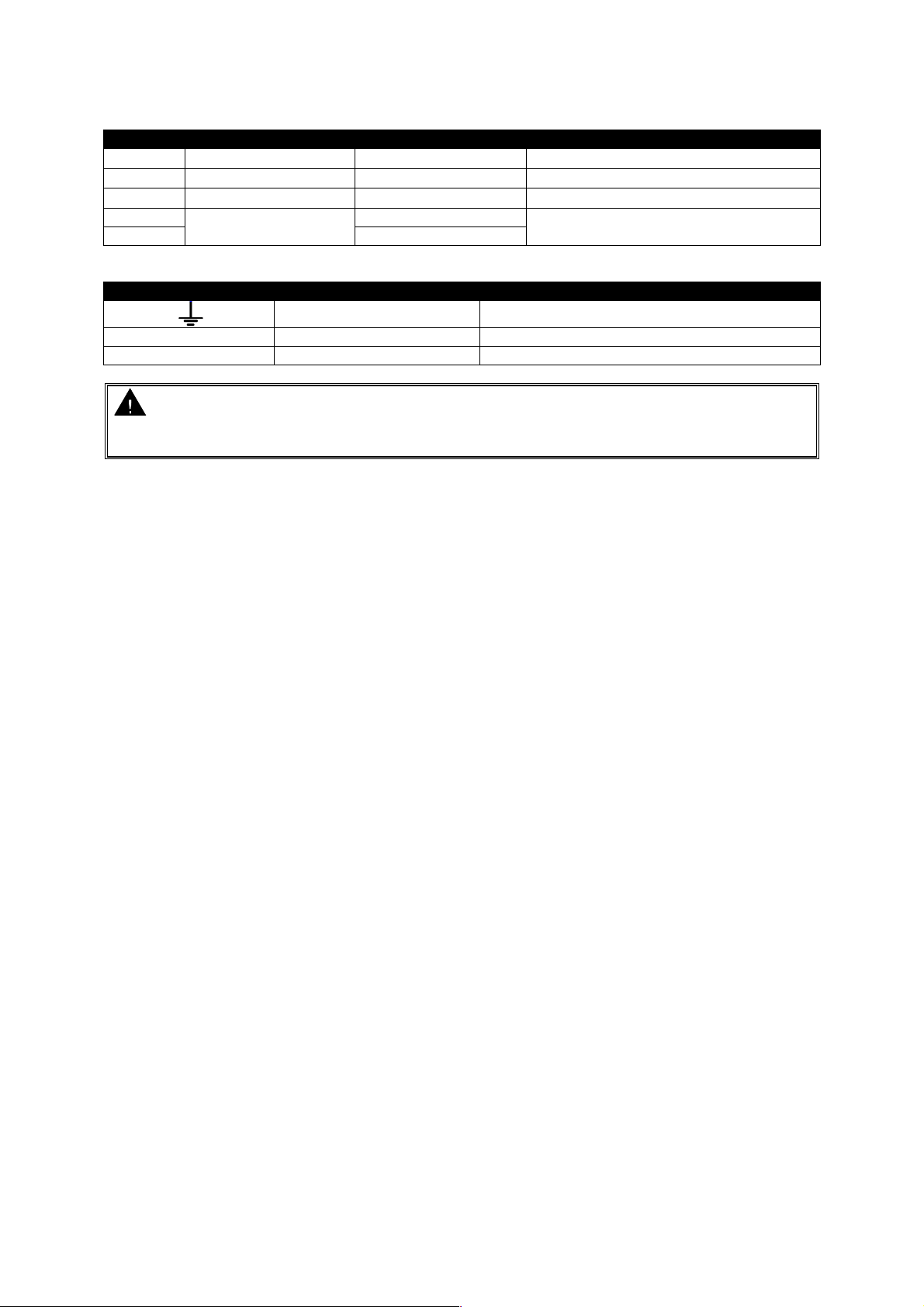
Connector B
Terminal
Function
Recommended size
Comments
Terminal
Function
Recommended S
ize
Installation
SCR RS485 screen 0.5mm² (AWG20)
A RS485 -ve 0.5mm² (AWG20)
B RS485 +ve 0.5mm² (AWG20)
NTC
NTC 0.5mm² (AWG20)
Connector C
CAUTION: Ensure Earth Terminal is connected to Battery negative (for negative earth
systems) or Battery positive (for positive earth systems)
Where no system earth exists, Earth Terminal must be connected to battery negative
PT1000 connection
terminals
N AC Neutral 1mm² (AWG 16)
L AC Live 1mm² (AWG 16)
0.5mm² (AWG20)
Earth 1mm² (AWG 16)
Use only 120Ω RS485 approved cable
Use only 120Ω RS485 approved cable
Use only 120Ω RS485 approved cable
Use only PT1000
48
Page 51
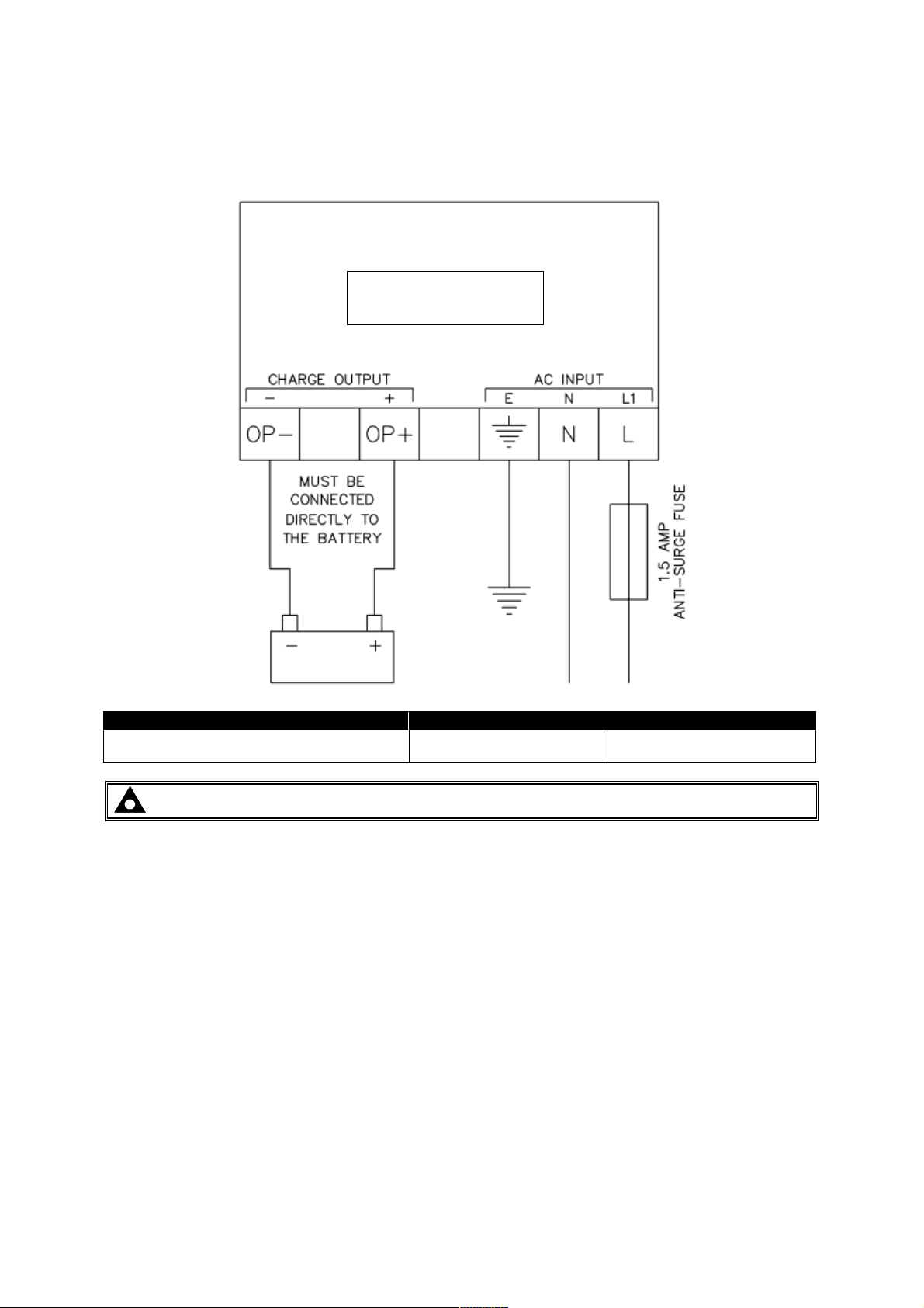
4.3 TYPICAL WIRING DIAGRAM
Recommended AC fuse
230V AC Input
110V AC Input
4.3.1 DSE9150
Installation
DSE9150
DSE9150 12V 2A charger (see Note below)
DSE9150 12V 3A charger
1.0A anti-surge
1.5A anti-surge
1.5A anti-surge
2.0A anti-surge
NOTE: DSE9150 12V 2A is no longer available and is included for legacy support only.
49
Page 52
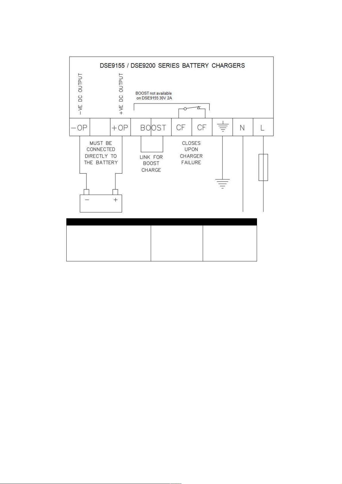
4.3.2 DSE9155 & DSE9200 SERIES
Recommended AC fuse
230V AC Input
110V AC Input
Installation
DSE9130 12V 5A charger
DSE9140 12V 10A charger
DSE9155 30V 2A charger
DSE9250 24V 3.7A charger
DSE9260 24V 10A charger
DSE9255 24V 5A charger
1.0A anti-surge
2.0A anti-surge
1.0A anti-surge
1.0A anti-surge
3.5 A anti-surge
2.0A anti-surge
2.0A anti-surge
3.5A anti-surge
2.5A anti-surge
2.5A anti-surge
6.3A anti-surge
3.5A anti-surge
50
Page 53
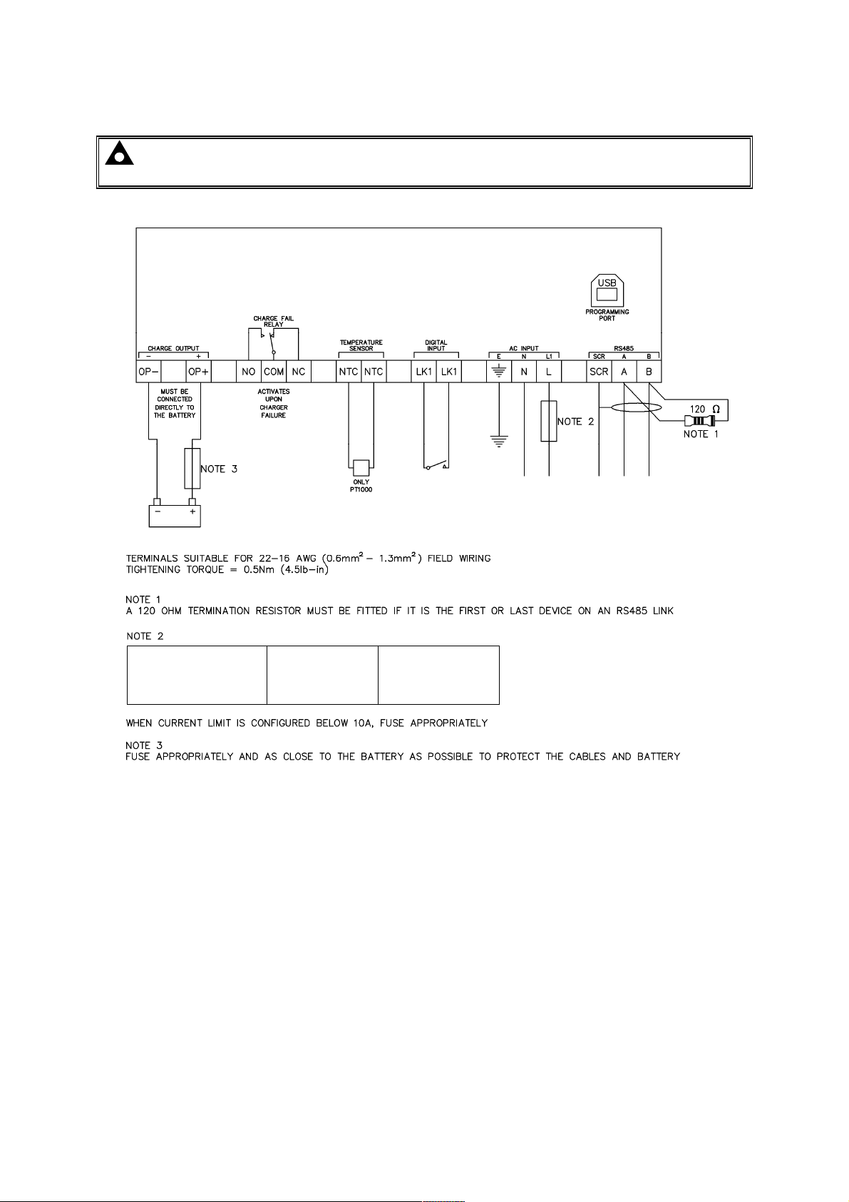
Installation
Recommended AC fuse
230V AC Input
110V AC Input
4.3.3 DSE9470 MKII, DSE9472 MKII, DSE9480 MKII, DSE9481 MKII
NOTE: For obsolete parts 9470-001-00 and 9480-001-00 contact DSE Technical Support for
connection details.
DSE9470 24V/12V 10A
DSE9480 12V/24V 10A
DSE9481 12V/24V 5A
DSE9472 24V/12V 5A
3.5A antisurge
3.5A antisurge
1.0A antisurge
2.0A antisurge
6.3A antisurge
6.3A antisurge
2.5A antisurge
3.5A antisurge
51
Page 54
Operation
Function
Action
Function
Action
5 INDICATIONS
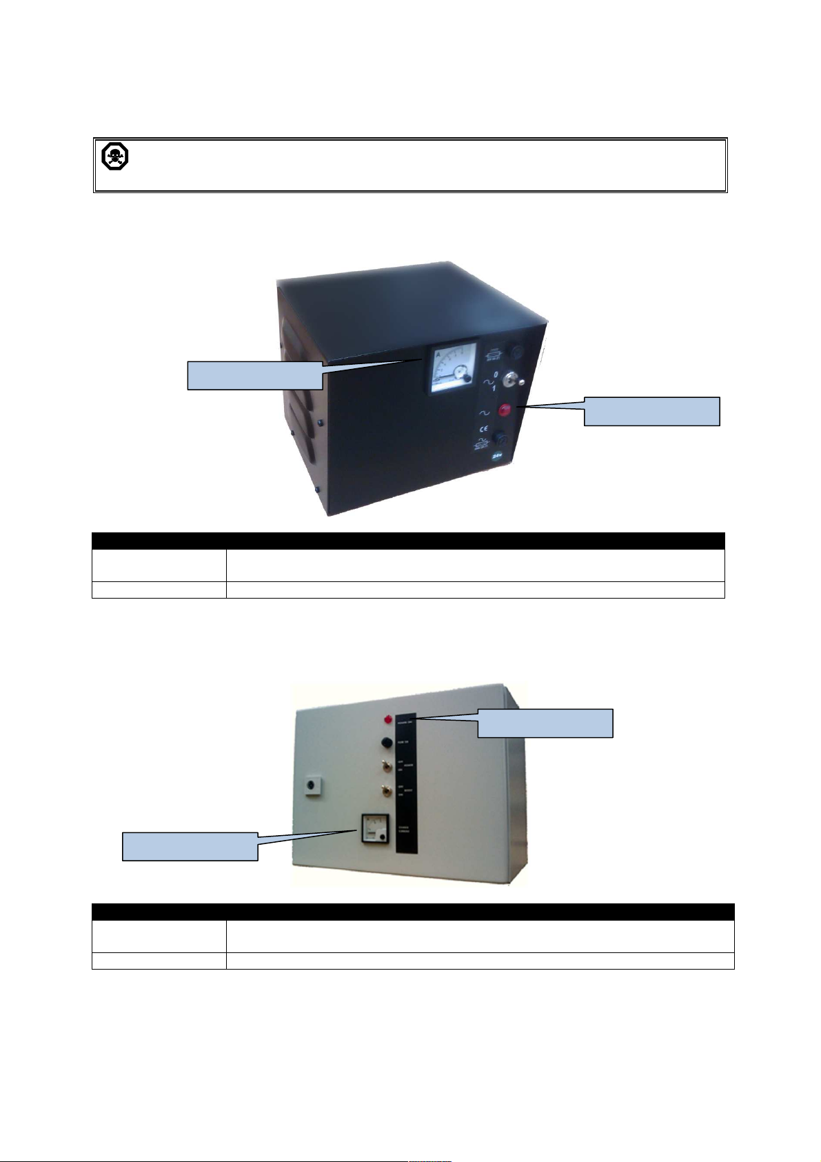
DANGER OF DEATH : LIVE PARTS exist within the DSE9000 enclosure. The enclosure
cover must not be removed when connected to an AC supply.
5.1 DSE907
Charge Ammeter
Power Indication
Power indication
Charge Ammeter Scaled 0A to 10A to show charge current (Max 5A charge)
Illuminated RED when AC power is connected and the POWER switch is in the
‘1’ position
5.2 DSE908
Power Indication
Charge Ammeter
Power indication
Charge Ammeter Scaled 0A to 15A to show charge current (Max 5A charge)
Illuminated RED when AC power is connected and the POWER switch is in the
ON position
52
Page 55
Operation
DSE
9130 12V 5A
Function
Colour
Action
•
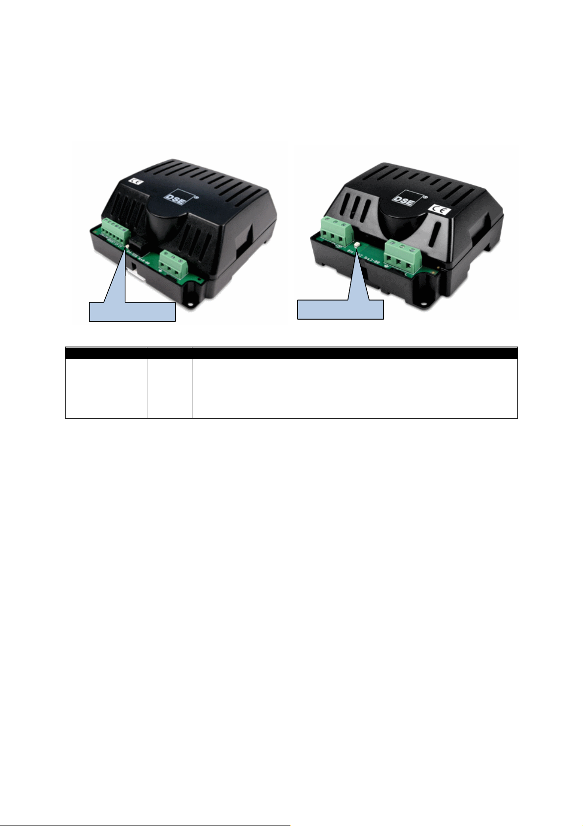
5.3 DSE9130, DSE9150, DSE9155, DSE9250 & DSE9255
DSE9155 30V 2A
DSE9250 24V 3.7A
DSE9255 24V 5A
Charger Status
LED Indications
Off when AC supply is not present or output volts are too low.
• Steady during normal operation with AC supply above minimum
Charger Status Red
operating voltage.
• Flashing when connected to an operating charging alternator.
• Pulsing during overload conditions.
Charger Status
DSE9150 12V 2A
DSE9150 12V 3A
53
Page 56
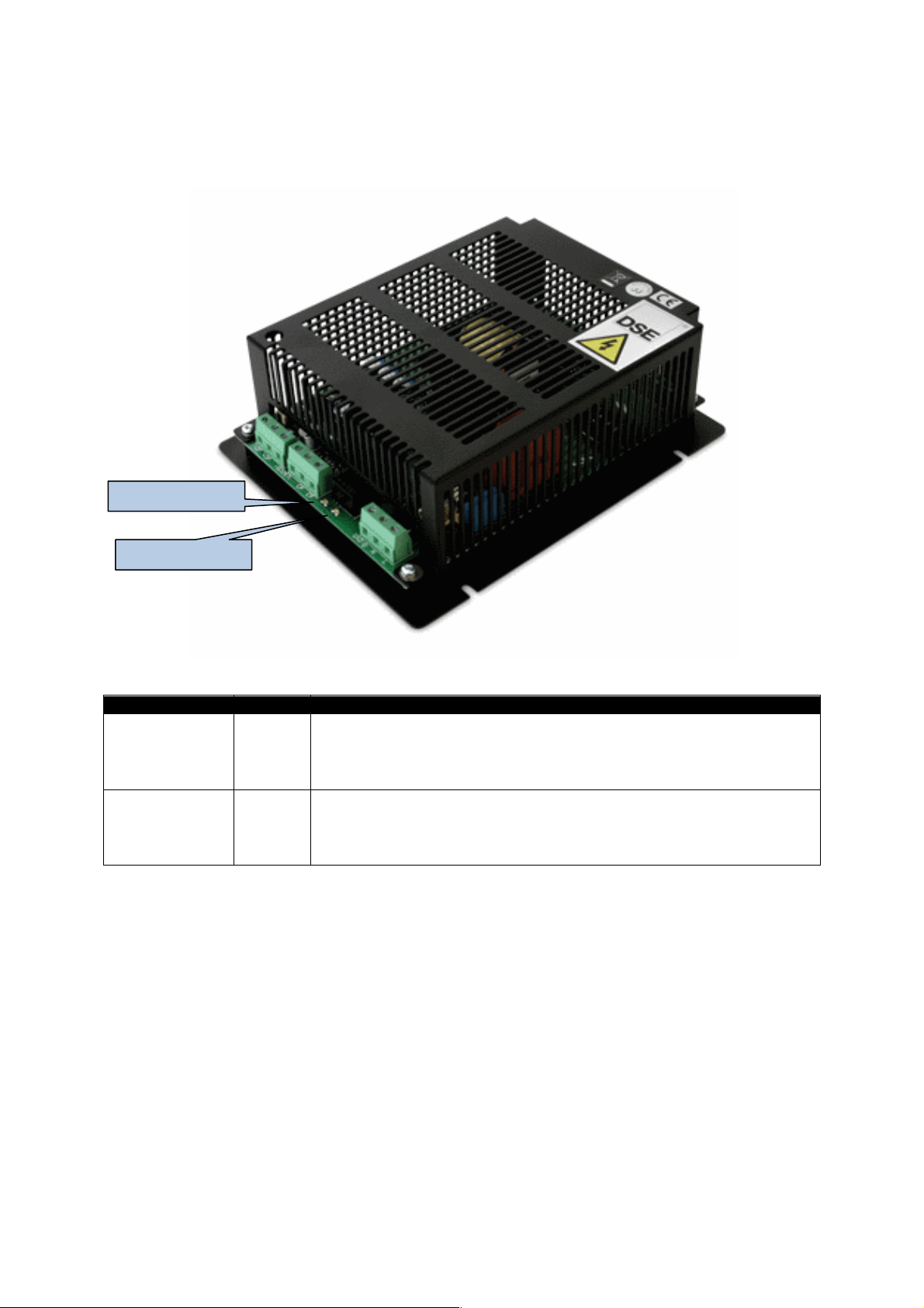
5.4 DSE9140 & DSE9260
DSE9140 12V 10
A
Function
LED
Acti on
•
•
Charger Status
Operation
DSE9260 24V 10A
Short Circuit
LED Indications
Off when AC supply is not present or output voltage is too low
Charger Status Red
Short circuit and
reverse polarity
indication
Green
• Steady during normal operation with AC supply above
minimum operating voltage
• Flashing when connected to an operating charging alternator
Off when AC supply is not present or output voltage is too low
• Steady during normal operation with AC supply above
minimum operating voltage
• Flashing during short circuit or reverse polarity conditions
54
Page 57
Operation
LED
DESIGNATION
OPE
FAULT 1
FAULT 2
LED DESIGNATION
LED
DESIGNATION
FAULT 1
FAULT 2
Boost Voltage
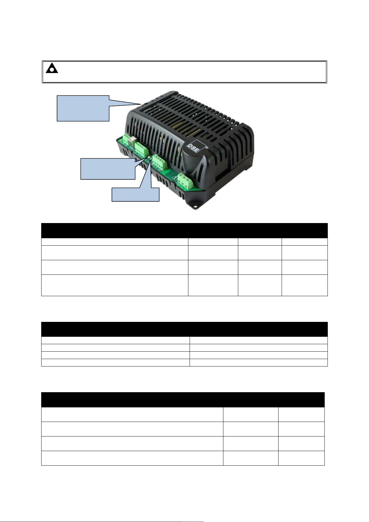
access hole
5.5 DSE9470 MKII, DSE9472 MKII, DSE9480 MKII, DSE9481 MKII
NOTE: For obsolete parts 9470-001-00 and 9480-001-00 contact DSE Technical Support for
LED descriptions.
potentiometer
Charger Status
(OPE)
Fault LEDs
5.5.1 STATUS
Condition
Charger Off Off Off Off
Battery not Detected (Battery Detection Mode)
Battery Connected (Battery Detection Mode)
Not Charging
(Charger is operating correctly but the ouput has
been disconnected from the battery)
Green
Constant
Green
Constant
Off
Red
Constant
Red
Constant
Red
Constant
Red
Flashing
Red
Constant
Red
Constant
5.5.2 CHARGE MODE
Mode
OPE
Bulk Charge in progress Yellow Constant
Absorption Charge in progress Yellow Flashing
Float Charge in Progress Green Constant
Storage Charge in Progress Green Flashing
5.5.3 FAULT CONDITIONS
Condition
High Output Voltage (DC)
High / Low Input Voltage (AC) or High Output Current (DC)
High Ambient / Charger Temperature, High Battery
Temperature (if enabled)
Short Circuit/ Reverse Polarity (DC Output Connection) Off
Red
Constant
Red
Flashing
Off
Off
Off
Red
Constant
Red
Flashing
55
Page 58

Operation
DSE9100 SERIES
DSE9200 SERIES
6 OPERATION
6.1 OPERATION OF DSE9100 SERIES / DSE9200 SERIES
DSE9130 12V 5A DSE9250 24V 3.7A
DSE9140 12V 10A DSE9255 24V 5A
DSE9150 12V 2A DSE9260 24V 10A
DSE9150 12V 3A
DSE9155 30V 2A
The DSE9100 & DSE9200 series of battery chargers can be used as a battery charger, DC power
supply, or both at the same time. For instance, the units can be used to power the generator control
panels and charge the panel batteries or starter batteries at the same time.
With no AC input to the charger, the Charge fail relay will be closed. This can be used to provide
indication of charger failure which operates upon mains supply AC supply failure or upon one of the
protections being activated.
6.1.1 PROTECTION
• Current limit to charger specification (2A or 3A depending upon charger model)
• Short circuit protection. Charger automatically restarts operation after the fault is removed.
• Reverse battery polarity protection. Charger automatically restarts operation after the fault is
removed.
6.1.2 PSU MODE
If no battery is connected to the output terminals, the DSE9100 & DSE9200 series battery charger will
operate as a DC power supply only, current limit is factory set. See the section entitled Specification
elsewhere in this manual for output specifications.
6.1.3 CHARGE MODE
Constant Voltage
The DSE9100 & DSE9200 series battery charger operates in Constant voltage current limited mode.
The charger output voltage is maintained at a constant level to allow the battery to charge while the
load does not exceed the maximum rating of the charger.
Once the battery is fully charged, the DSE9100 & DSE9200 series battery charger will switch to ECO-
POWER mode. This is a low power use standby mode.
Current Limit
If the load on the battery charger (battery charge demand+standing load) exceeds the maximum
current rating of the charger, the charging current is limited to the maximum rating of the charger and
the voltage is reduced.
The voltage will rise to the rated voltage again once the load drops below the maximum rating of the
charger.
56
Page 59
Operation
Charging time
Charge time is often of little consequence when the battery is used in a standby operation. An
example of this is when the battery is used to supply the starting system of a diesel generator. During
normal operation, the battery is at full capacity and the battery charger is used to maintain the float
voltage of the battery. The battery is only drained when the generator is called to start. As the
generator has a DC charging alternator fitted, the battery is quickly recharged when the generator is
running. Should the generator stop before the battery is fully recharged, the DSE9100 & DSE9200
series will continue to recharge the battery until it is fully charged.
Typically a battery will charge from flat to 80% capacity in 16hrs when when charged at C/10.
For example charging a 50Ah battery for 16hrs at 5A will charge the battery to 80% of its full capacity.
Remember to take into account any other standing load such as control panel requirements when
calculating how much power is ‘left’ to charge the battery.
6.1.4 BOOST MODE
(Not applicable to DSE9150 12V 2A, DSE9150 12V 3A or DSE9155 30V 2A)
CAUTION: Boost mode is intended for equalisation of the cells in lead acid batteries and
should not be operated when the battery charger is connected to other battery types or when
the charger is used as a power supply only. If in doubt, consult your battery manufacturer.
Boost mode is operated by connecting the BOOST terminals together (for instance with an external
switch or timer circuit). This will raise the battery charger floating voltage by 0.8V DC.
57
Page 60
Operation
DSE9400
SERIES
6.2 OPERATION OF DSE9400 MKII SERIES
DSE9470 MKII 24V/12V 10A
DSE9472 MKII 24V/12V 5A
DSE9480 MKII 12V/24V 10A
DSE9481 MKII 12V/24V 5A
The DSE9400 MKII Series battery charger can be used as a battery charger, DC power supply, or
both at the same time. For instance, the unit can be used to power the generator control panels and
charge the panel batteries or starter batteries at the same time.
With no AC input to the charger, the Fault relay is in it’s inactive state. This volts-free change over
relay can be used to provide indication of alarms as detailed in the Protection section below.
When a suitable AC supply is connected, operation of the unit will depend upon the load connected to
the unit’s output terminals :
NOTE: For details of Battery Charger Configuration, you are referred to DSE Publication:
057-159 DSE9400 Series Battery Charger Configuration Suite Manual.
6.2.1 PROTECTION
Alarms fall into two categories :
• Factory Configured, non-ajustable alarms.
• User Configurable Alarms, adjustable by DSE Configuration Suite PC Software.
6.2.1.1 FACTORY CONFIGURED ALARMS
Under the following conditions, the Fault Relay de-energises and charging is stopped (DC output is
disabled) :
• Mains voltage > 310V (rms)
• Mains voltage
• Battery temperature > 60 ºC (if temperature compensation is enabled)
• Battery Charger ambient temperature> 85 ºC
• DC output voltage > 110% of Boost Voltage
• Short circuit / reverse polarity of the DC output.
6.2.1.2 USER CONFIGURABLE ALARMS
< 85V (rms)
NOTE: For details of Battery Charger Configuration, you are referred to DSE Publication:
057-159 DSE9400 Series Battery Charger Configuration Suite Manual.
The following alarms are user configurable using DSE Configuration Suite PC Software. In each case,
the Fault relay de-energises.
• DC Overcurrent alarm
• DC Overvoltage alarm
• Battery Temperature alarm. Activation of this alarm places the charger into Float mode.
• Mains Over Voltage alarm. Activation of this alarm places the charger into Float mode.
• Mains Under Voltage alarm. Activation of this alarm places the charger into Float mode.
58
Page 61

Operation
Charge Mode
Effect o
n boost voltage
Potentiometer has no effect on
Float Voltage
Potentiometer has no effect on
Storage Voltage
6.2.2 DIGITAL INPUT
The DSE9400 series is fitted with a configurable digital input. Configuration is m ade using the DSE
Configuration Suite PC Software.
The Factory Setting for the digital input provides a 12V / 24V selection function.
6.2.3 VOLTAGE ADJUSTMENT POTENTIOMETER
A manually operated potentiometer is provided to make small adjustments to the Boost Voltage
without the requirement f or the DSE Configuration Suite PC Software.
This is primarily intended to increase charger output to cater for voltage drop in long connection
cables.
The potentiometer adjusts the boost voltage byup to ±1.7V. This is subject to an absolute maximum
of 29.5V.
The table below shows the effect of the potentiometer on the boost voltage in the various charging
modes.
Bulk 100% of potentiometer setting
Absorption 50% of potentiometer setting
Float
Storage
6.2.4 PSU MODE
If no battery is connected to the output terminals, the battery charger will operate as a DC power
supply only, current limit is factory set to 10A and is adjustable (2A – 10A) using the DSE
Configuration Suite PC Software. See the section entitled Specification elsewhere in this manual for
further output specifications.
59
Page 62
Operation
6.2.5 CHARGE MODE
NOTE: For details of Battery Charger Configuration, you are referred to DSE Publication:
057-159 DSE9400 Series Battery Charger Configuration Suite Manual.
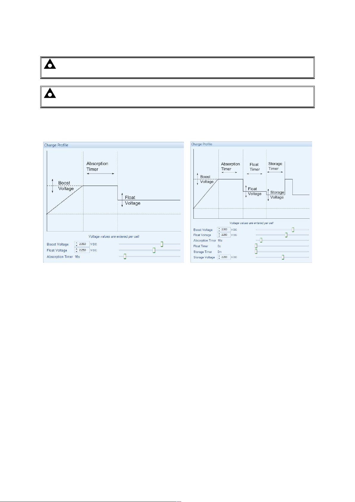
NOTE: Should a 2-Stage charging profile be required, select a 3-Stage profile and
configure Boost Voltage and Float Voltage to the same value.
Using DSE Conifiguration Suite PC Software, the battery charger is configured to use either a 3Stage Charge or 4-Stage Charge profile as shown below. The description of each charge mode is
given in the following sections.
Absorption Float Storage
Bulk Absorption
Bulk
Float
3-Stage Charge Profile Configuration 4-Stage Charge Profile Configuration
6.2.5.1 BULK CHARGE
The battery charger operates in Constant voltage current limited mode.
The charger output voltage is maintained at a constant level (boost voltage) to allow the battery to
charge while the load does not exceed the maximum rating of the charger.
If the load on the battery charger (battery charge demand+standing load) exceeds the maximum
current rating of the charger, the charging current is limited to the maximum rating of the charger and
the voltage is reduced.
The voltage will rise to the rated voltage again once the load drops below the maximum rating of the
charger. This may occur naturally as the battery charges.
As the battery charges and the charge current drops below 75% of the current rating, Absorption
mode is entered.
6.2.5.2 ABSORPTION
This mode is active for the duration of the Absorption Timer. This is adjustable using the DSE
Configuration Suite PC Software.
Absorption mode is used to complete the charging process, bringing the battery to 100% charged
status.
After the Absorption timer, float charge mode is entered.
60
Page 63

Operation
6.2.5.3 FLOAT CHARGE
The battery charger DC voltage is lowered to the configured f loat voltage.
Float Charge is used to provide a small amount of current to the battery, to overcome internal losses
and keep the battery at it’s 100% charged state. The battery can be left in this mode indefinitely.
6.2.5.4 STORAGE
When configured to use a four stage charging profile, a time limited storage charge is periodically
entered (storage timer) to maintain the battery charge at optimum levels. This occurs at the level of
the storage voltage. This is adjustable using the DSE Configuration Suite PC Software.
When the storage timer expires, the charger re-enters the Absorption mode.
Additionally, this is used as an ‘Automatic Boost’ facility, to periodically attempt to remove sulfation
from the battery plates.
6.2.5.5 CHARGING TIME
Charge time is often of little consequence when the battery is used in a standby operation. An
example of this is when the battery is used to supply the starting system of a diesel generator. During
normal operation, the battery is at full capacity and the battery charger is used to maintain the float
voltage of the battery. The battery is only drained when the generator is called to start. As the
generator has a DC charging alternator fitted, the battery is quickly recharged when the generator is
running. Should the generator stop before the battery is fully recharged, the DSE9400 MKII Series
battery charger will continue to recharge the battery until it is fully charged.
Typically a battery will charge from flat to 80% capacity in 16hrs when when charged at C/10.
For example charging a 50Ah battery for 16hrs at 5A will charge the battery to 80% of its full capacity.
Remember to take into account any other standing load such as control panel requirements when
calculating how much power is ‘left’ to charge the battery.
6.2.5.6 MANUAL BOOST
NOTE: The Digital Input must be configured to Manual Boost to provide this function.
For further details, you are referred to DSE Publication: 057-159 DSE9400 Series Battery
Charger Configuration Suite Manual.
Manual boost will place the charger into Bulk Charge mode, charging at the level of the boost voltage.
A typical use of manual boost is with Lead Acid type batteries. When the battery is fully charged,
placing the charger into boost mode will raise the output voltage. This has the effect of gassing the
battery, helping to remove sulfation from the battery plates and helping the cells to equalise in
voltage.
6.2.6 TEMPERATURE COMPENSATION
NOTE: For details of Battery Charger Configuration, you are referred to DSE Publication:
057-159 DSE9400 Series Battery Charger Configuration Suite Manual.
If temperature compensation is enabled through configuration, and remote temperature sensor is
connected, the output voltage automatically varies by a configureable voltage per cell for each 1°C
deviation from 20°C, within the range of -20°C to 60°C. Increasing temperature gives decreasing
output voltage and increasing temperatures gives increasing output voltage..
The battery temperature is measured by a 2 wire PT1000 sensor placed on the battery itself.
61
Page 64

7 FAULT DIAGNOSIS
Nature of problem
Suggest
ion
Check that the incoming AC supply is correctly connected and within
limits and check the integrity of any external fuse that may be fitted.
The charger is not operating
Charge fail relay
continuously operated
Batteries fail to charge
Charge time is too long
Ensure the charger is not being operated above the maximum
temperature specification.
Check the LED indications against the LED descriptions listed
elsewhere in this document.
Check the connected load of the charger is not reverse connected or
short circuit.
Check the batteries using the battery manufacturers
recommendations.
Typically a battery will charge from flat to 80% capacity in 16hrs when
when charged at C/10.
For example charging a 50Ah battery for 16hrs at 5A will charge the
battery to 80% of its full capacity.
Remember to take into account any other standing load such as
control panel requirements when calculating how much power is ‘left’
to charge the battery.
Fault Diagnosis
62
Page 65

This page is intentionally left blank.
8 MAINTENANCE, SPARES, REPAIR AND SERVICING
The DSE battery chargers are designed to be Fit and Forget. As such, there are no user serviceable
parts. In the case of malfunction you should contact your original equipment supplier (OEM).
9 WARRANTY
DSE provides limited warranty to the equipment purchaser at the point of sale. For full details of any
applicable warranty, you are referred to your original equipment supplier (OEM).
10 DISPOSAL
10.1 WEEE (WASTE ELECTRICAL AND ELECTRONIC EQUIPMENT)
Directive 2002/96/EC
If you use electrical and electronic equipment you must store, collect, treat,
recycle and dispose of WEEE separately from your other waste.
10.2 ROHS (RESTRICTION OF HAZARDOUS SUBSTANCES)
Directive 2002/95/EC:2006
To remove specified hazardous substances (Lead, Mercury, Hexavalent Chromium, Cadmium, PBB &
PBDE´s)
Exemption Note: Category 9. (Monitoring & Control Instruments) as defined in Annex 1B of the WEEE
directive will be exempt from the RoHS legislation. This was confirmed in the August 2005 UK´s
Department of Trade and Industry RoHS REGULATIONS Guide (Para 11).
Despite this exemption DSE has been carefully removing all non RoHS compliant components from
our supply chain and products.
When this is completed a Lead Free & RoHS compatible manufacturing process will be phased into
DSE production.
This is a process that is almost complete and is being phased through different product groups.
63
Page 66

This page is intentionally left blank.
Page 67
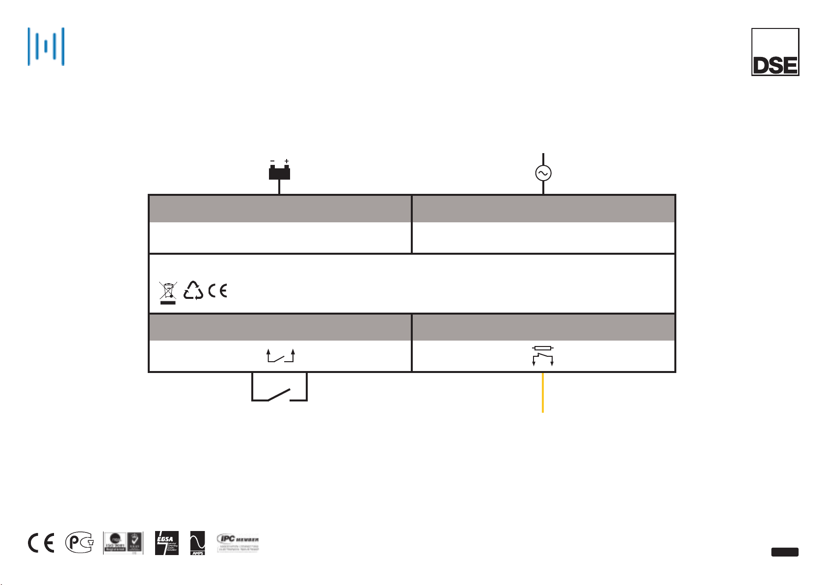
®
DSEPower
DSE9130, 9150, 9155 & 9255
COMPACT BATTERY CHARGERS
2 AMP & 5 AMP OPTIONS
ISSUE 5
CHARGE OUTPUT AC POWER SUPPLY
7
OTHER
DSE9000
CHARGE BOOST
INPUT
N/C VOLT FREE CHARGE
FAIL OUTPUT
1 1
COMPATIBLE WITH ALL DSE MODULES
1ph
N
Page 68
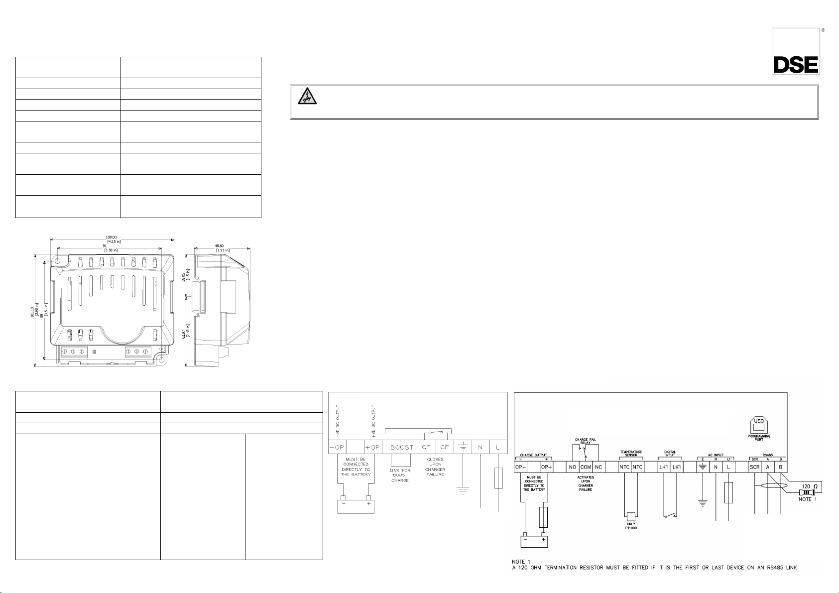
Typical Wiring Diagrams
cover must not
Dimensions and Mounting
Dimensi ons i n m m unl ess stated
Recommended AC fuse
230V AC Input
110V AC Input
DSE9150 12V 2A
DSE9150 12V 3A
Overall size 108mm x 101mm x 49mm
Weight 0.16kg
Mounting type DIN rail or chassis mounting
(4.25” x 3.98” x 1.91”)
Din rail type EN 50022 35mm type only
Mounting holes Suitable for M4
Mounting hole centres 91mm x 89mm
(4.25” x 3.51”)
Input voltage (nominal) 110V-240V
Input voltage (absolute
90V-250V
range)
Charge failure relay
3A DC resistive, 30V maximum
rating
Operating Temperature
-30°C to 55°C
(-22°F to 131°F)
053-049
ISSUE 13
DSE9xxx Battery Charger Installation Instructions
DEEP SEA ELECTRONICS
DANGER OF DEATH : LIVE PARTS exist within the DSE9xxx enclosures. The enclosure
be removed.
Installation
The DSE9xxx battery chargers are designed to be mounted within a control panel, on the panel DIN rail utilising the integral mounts
or on a chassis utilising the mounting holes. For dimension and mounting details, see overleaf.
The DSE9xxx battery chargers are fit-and-forget. It can be permanently connected to the supply and the load, with no requirement to
disable the charger during times of heavy load (such as engine cranking) or when in parallel with a charging alternator.
Battery suitability
The charger is factory set by DSE to suit Lead Acid batteries. The DSE91xx & DSE92xx battery chargers can be adjusted at the time
of ordering to suit other battery types. The DSE947x MKII & DSE948x MKII battery chargers are configured using the DSE
Configuraiton Suite to suit other battery types.
Care should be taken to ensure the batteries connected to the charger are of the correct ‘technology’ to suit the setting of the
charger.
Indications
The DSE9xxx Battery Chargers feature an LED indicator(s) to show the battery charger Status.
(Refer to DSE publication: 057-085 DSE9xxx Series Operator Manual for further information)
Boost Mode
(Not applicable to DSE9150 12V 2A or DSE9155 30V 2A)
(DSE947x & DSE948x MKII Series Only. Boost feature is controlled automatically, no external connection needed.)
Boost mode is operated by connecting the BOOST terminals together (for instance with an external switch or timer circuit. This will
raise the battery charger floating voltage by 0.8V DC.
Caution:- Boost mode is intended for equalisation of cells in lead acid batteries.
Connection type Screw terminal, rising clamp, no
internal spring
Min cable size 0.5mm² (AWG 20)
Max cable size 2.5mm² (AWG 14)
DSE9130 12V 5A charger
DSE9140 12V 10A charger
DSE9150 12V 3A charger
DSE9155 30V 2A charger
DSE9250 24V 3.7A charger
DSE9255 24V 5A charger
DSE9260 24V 10A charger
DSE9470 MKII 24V 10A charger
DSE9472 MKII 24V 5A charger
DSE9480 MKII 12V 10A charger
DSE9481 MKII 12V 5A charger
1.0A anti-surge
2.0A anti-surge
1.0A anti-surge
1.0A anti-surge
1.0A anti-surge
2.0A anti-surge
3.5A anti-surge
3.5A anti-surge
2.0A antisurge
2.0A anti-surge
1.0A antisurge
2.0A anti-surge
3.5A anti-surge
1.5A anti-surge
2.5A anti-surge
2.5A anti-surge
3.5A anti-surge
6.3A anti-surge
6.3A anti-surge
3.5A anti-surge
3.5A anti-surge
2.5A anti-surge
DSE 91xx & 92xx Series
Battery Chargers
CF not available on
Boost not available on
DSE9150 12V 3A
DSE9155 30V 2A
DSE 947x & 948x MKII Battery Chargers
Page 69
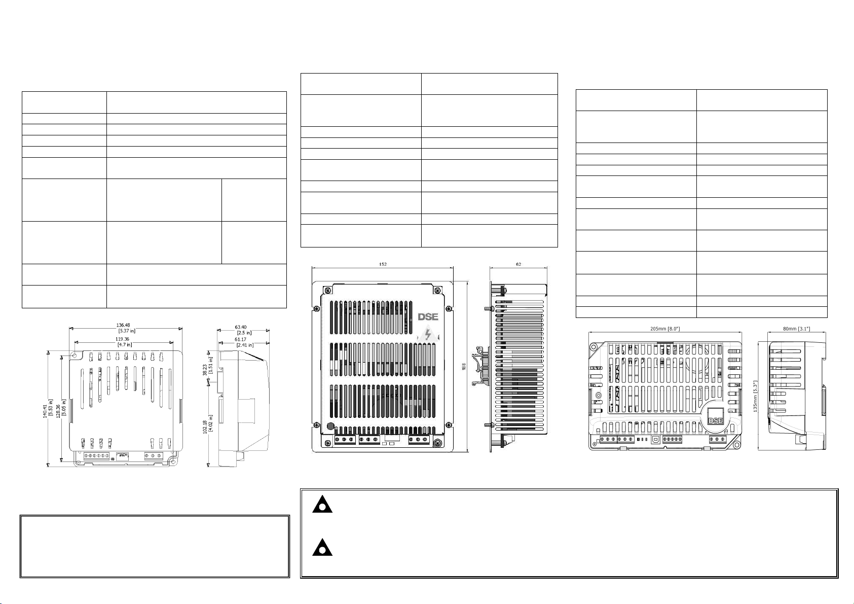
Dimensions and Mounting
°
Dimensions and Mounting
°
Dimensions and Mounting
Intelligent Battery Chargers
DSE9481 MKII 12V 5A
DSE9480 MKII 12V 10A
°
2.44in
DSE9130 12V 5A DSE9250 24V 3.7A *
DSE9155 30V 2A DSE9255 24V 5A
* This model is no longer available
Overall size 136mm x 140mm x 63mm
Weight 0.5kg
Mounting type DIN rail or chassis mounting
Din rail type EN 50022 35mm type only
Mounting holes Suitable for M4
Mounting hole
centres
Input voltage
(nominal)
Input voltage
(absolute range)
Charge failure
relay rating
Operating
Temperature
(5.37” x 5.53” x 2.5”)
119.36mm x 128.36mm
(4.7” x 5.05”)
DSE9250-001 24V 3.7A
DSE9250-002 24V 3.7A
DSE9130 12V 5A
DSE9255 24V 5A
DSE9250-001 24V 3.7A
DSE9250-002 24V 3.7A
DSE9130 12V 5A
DSE9255 24V 5A
3A DC resistive, 30V maximum
C to 55°C
-30
(-22°F to 131°F)
110V-240V
110V-277V
110V-277V
110V-277V
90V-265V
90V-305V
90V-305V
90V-305V
DSE9140 12V 10A
DSE9260 24V 10A
Overall size 152mm x 188mm x 62mm
(6” x 7.4”x 2.44”)
Weight
DSE9140 12V 10A
DSE9260 24V 10A
Mounting type DIN rail or chassis mounting
Din rail type EN 50022 35mm type only
Mounting holes Suitable for M4
Mounting hole centres 142mm x 128mm
Input voltage (nominal) 110V-277V
Input voltage
(absolute range)
Charge failure relay rating 3A DC resistive 30V Maximum
Operating Temperature
0.75kg
0.85kg
(5.59” x 5.0”)
90V-305V
C to 55°C
-30
(-22°F to 131°F)
6in
DSE9472 MKII 24V 5A
Overall size 205mm x 135mm x 80mm
Weight
DSE9470 MKII
DSE9472/80/81 MKII
Mounting type DIN rail or chassis mounting
Din rail type EN 50022 35mm type only
Mounting holes Suitable for M4
Mounting hole centres 190mm x 120mm
Input voltage (nominal) 110V-277V
Input voltage
(absolute range)
Charge failure relay rating 3A DC resistive
Operating Temperature
Optional Temperature
Sensor
Communications RS485
PC connection (USB) To enable PC Configuration
DSE9470 MKII 24V 10A
(8.1” x 5.3” x 3.1”)
0.78kg
0.7kg
(7.5” x 4.7”)
95V-305V
30V maximum
C to 85°C with de-rating
-30
(-22°F to 185°F)
NTC connections for PT1000
sensor only
Dimensions in mm unless stated
Deep Sea Electronics Plc.
Tel:+44 (0)1723 890099
Fax: +44 (0)1723 893303
Email: [email protected]
Web: www.deepseaplc.com
Deep Sea Electronics Inc.
Phone: +1 (815) 316-8706
Fax: +1 (815) 316- 8708
Email: [email protected]
Web: www.deepseausa.com
7.4 in
Dimensions in mm unless stated
Dimensions in mm unless stated
NOTE : DSE9000 series chargers are designed to be mounted with the base to a vertical surface with
the terminal strips at the bottom.
NOTE : This document is intended as a ‘quick start’ guide only. For full operating instructions and
specifications, refer to DSE publication: 057-085 DSE9xxx Series Operator Manual
 Loading...