

DSE DSE9000 Series Operator's Manual

DSE9000 Series Battery Charger Operator Manual ISSUE 11
DEEP SEA ELECTRONICS PLC
DSE9000 SERIES BATTERY CHARGER
OPERATOR MANUAL
Document Number: 057-085
Author: Ashley Senior

DSE9000 Series Battery Charger Operator Manual
2
Deep Sea Electronics Plc
Highfield House
Hunmanby
North Yorkshire
YO14 0PH
ENGLAND
Sales Tel: +44 (0) 1723 890099
Sales Fax: +44 (0) 1723 893303
E-mail: sales@deepseaplc.com
Website: www.deepseaplc.com
DSE9000 Series Battery Charger Operator Manual
© Deep Sea Electronics Plc
All rights reserved. No part of this publication may be reproduced in any material form (including
photocopying or storing in any medium by electronic means or other) without the written permission of
the copyright holder except in accordance with the provisions of the Copyright, Designs and Patents
Act 1988.
Applications for the copyright holder’s written permission to reproduce any part of this publication
should be addressed to Deep Sea Electronics Plc at the address above.
Any reference to trademarked product names used within this publication is owned by their respective
companies.
Deep Sea Electronics Plc reserves the right to change the contents of this document without prior
notice.
Amendments since last publication
Amd. No.
Comments
1 Added Efficiency curve of 2A charger
2 Updated specs table of 3.7A charger
3 Added 5A DSE9255 charger and 9250-002 277V input charger
4 Added DSE9155 30V 2A charger (Issue7)
5 Added 10A charger (Issue8)
6 Added Indication (LED) for 10A chargers (Issue 8.1)
7 Added detail regarding -002- chargers asnd cabinet/industrial chargers (Issue 8.2)
8 Added 9400 series (Issue 9)
8.1 Corrected specs for 9140.
9 Removed all DSE9400 series chargers, added DSE9470. (Issue 10)
10 Added new DSE9400 series Chargers (Issue 11)
Typeface : The typeface used in this document is Arial. Care should be taken not to mistake the upper
case letter I with the numeral 1. The numeral 1 has a top serif to avoid this confusion.

DSE9000 Series Battery Charger Operator Manual
3
1 BIBLIOGRAPHY .................................................................................................. 5
1.1 INSTALLATION INSTRUCTIONS ........................................................................................... 5
1.2 MANUALS ................................................................................................................................ 5
3 SPECIFICATIONS ............................................................................................... 7
3.1.2 DSE0907 INDUSTRIAL / DSE0908 CABINET MOUNTED BATTERY CHARGERS ....... 8
3.2 PROTECTION .......................................................................................................................... 9
3.2.1 DSE9200 SERIES AND DSE9400 SERIES ..................................................................... 9
3.3 COMMON ELECTRICAL SPECIFICATIONS ........................................................................ 10
3.4 DSE9470 COMMUNICATION PORT USAGE ...................................................................... 12
3.4.1 USB CONNECTION ........................................................................................................ 12
3.4.2 RS485 .............................................................................................................................. 13
3.6 OUTPUT SPECIFICATIONS .................................................................................................. 14
3.6.1 DSE9130 12V 5A ............................................................................................................ 14
3.6.2 DSE9140 12V 10A .......................................................................................................... 15
3.6.3 DSE9150 12V 2A ............................................................................................................ 16
3.6.4 DSE9155 30V 2A ............................................................................................................ 17
3.6.5 DSE9250 24V 3.7A ......................................................................................................... 18
3.6.6 DSE9255 24V 5A ............................................................................................................ 19
3.6.7 DSE9260 24V 10A .......................................................................................................... 20
3.6.8 DSE9470 24V 10A .......................................................................................................... 21
3.6.9 DSE9472 24V 5A ............................................................................................................ 23
3.6.10 DSE9480 12V 10A .......................................................................................................... 24
3.6.11 DSE9481 12V 5A ............................................................................................................ 26
3.7 DIMENSIONS AND MOUNTING ........................................................................................... 27
3.7.1 DSE0907 12V 10A INDUSTRIAL BATTERY CHARGER ............................................... 27
3.7.2 DSE0908 12V & 24V 10A CABINET MOUNTED BATTERY CHARGER....................... 28
3.7.3 DSE9130 12V 5A ............................................................................................................ 29
3.7.4 DSE9150 12V 2A ............................................................................................................ 30
3.7.5 DSE9140 12V 10A .......................................................................................................... 31
3.7.6 DSE9155 30V 2A ............................................................................................................ 32
3.7.7 DSE9250 24V 3.7A ......................................................................................................... 33
3.7.8 DSE9255 24V 5A ............................................................................................................ 34
3.7.9 DSE9260 24V 10A .......................................................................................................... 35
3.7.10 DSE9470 24V 10A .......................................................................................................... 36
3.7.11 DSE9472 24V 5A ............................................................................................................ 37
3.7.12 DSE9480 12V 10A .......................................................................................................... 38
3.7.13 DSE9481 12V 5A ............................................................................................................ 39
3.8 APPLICABLE STANDARDS ................................................................................................. 40
4 INSTALLATION ................................................................................................. 41
4.1 BATTERY SUITABILITY ....................................................................................................... 41
4.2 USER CONNECTIONS .......................................................................................................... 41
4.2.1 DSE9130, DSE9140, DSE9250, DSE9255, DSE9260 ................................................... 42
4.2.2 DSE9150 ......................................................................................................................... 42
4.2.3 DSE9155 ......................................................................................................................... 43
4.2.4 DSE9400 SERIES ........................................................................................................... 43
4.3 TYPICAL WIRING DIAGRAM ................................................................................................ 44
4.3.1 DSE9100 / DSE9200 SERIES ........................................................................................ 44
4.3.2 DSE9400 SERIES ........................................................................................................... 45
5 INDICATIONS .................................................................................................... 46
5.1 DSE0907 ................................................................................................................................ 46
5.2 DSE0908 ................................................................................................................................ 46
5.3 DSE9130, DSE9150, DSE9155, DSE9250 & DSE9255 ........................................................ 47
5.4 DSE9140 & DSE9260 ............................................................................................................ 48
5.5 DSE9400 SERIES .................................................................................................................. 49
6 OPERATING MODES ........................................................................................ 50

DSE9000 Series Battery Charger Operator Manual
4
6.1 OPERATION OF DSE9100 SERIES / DSE9200 SERIES ..................................................... 50
6.1.1 PSU MODE ..................................................................................................................... 50
6.1.2 CHARGE MODE ............................................................................................................. 50
6.1.3 BOOST MODE ................................................................................................................ 51
6.2 OPERATION OF DSE9400 SERIES ...................................................................................... 52
6.2.1 PSU MODE ..................................................................................................................... 52
6.2.2 CHARGE MODE ............................................................................................................. 52
6.2.3 BOOST MODE ................................................................................................................ 53
6.2.4 TEMPERATURE COMPENSATION ............................................................................... 53
7 FAULT DIAGNOSIS .......................................................................................... 54
8 MAINTENANCE, SPARES, REPAIR AND SERVICING ................................... 55
9 WARRANTY ...................................................................................................... 55
10 DISPOSAL ...................................................................................................... 55
10.1 WEEE (WASTE ELECTRICAL AND ELECTRONIC EQUIPMENT) ................................. 55
10.2 ROHS (RESTRICTION OF HAZARDOUS SUBSTANCES) .............................................. 55

Bibliogprahy
5
1 BIBLIOGRAPHY
This document refers to and is referred to by the following DSE publications which can be obtained
from the DSE website www.deepseaplc.com
1.1 INSTALLATION INSTRUCTIONS
Installation instructions are supplied with the product in the box and are intended as a ‘quick start’
guide only.
DSE PART
DESCRIPTION
053-049 DSE9000 Battery Charger Installation Instructions
1.2 MANUALS
DSE PART
DESCRIPTION
057-159 DSE9400 Series Battery Charger Configuration Suite Manual

Introduction
6
2 INTRODUCTION
NOTE:
NOTE: NOTE:
NOTE: This document DOES NOT contain details of the ‘obsolete’ DSE9210 and
This document DOES NOT contain details of the ‘obsolete’ DSE9210 and This document DOES NOT contain details of the ‘obsolete’ DSE9210 and
This document DOES NOT contain details of the ‘obsolete’ DSE9210 and
DSE9240 battery chargers. For further details of these units, please contact Deep
DSE9240 battery chargers. For further details of these units, please contact Deep DSE9240 battery chargers. For further details of these units, please contact Deep
DSE9240 battery chargers. For further details of these units, please contact Deep Sea
Sea Sea
Sea
Electronics.
Electronics.Electronics.
Electronics.
This document details the installation requirements of the DSE9000 series range of battery chargers.
The manual forms part of the product and should be kept for the entire life of the product. If the
product is passed or supplied to another party, ensure that this document is passed to them for
reference purposes.
This is not a controlled document. You will not be automatically informed of updates. Any future
updates of this document will be added to the DSE website at www.deepseaplc.com.
The DSE9000 series modules are intended for mounting within a customer enclosure or panel (DIN
rail mounting or fastened by screws/bolts).
DSE also supply some of the battery chargers as completed units, factory mounted into enclosures for
wall or floor mounting.
The DSE9000 series chargers fulfill the most common functions required of a charger in the
generating set industry. Combining protected outputs, intelligent charging and power supply operation
with a robust enclosure.
Specifications
7
3 SPECIFICATIONS
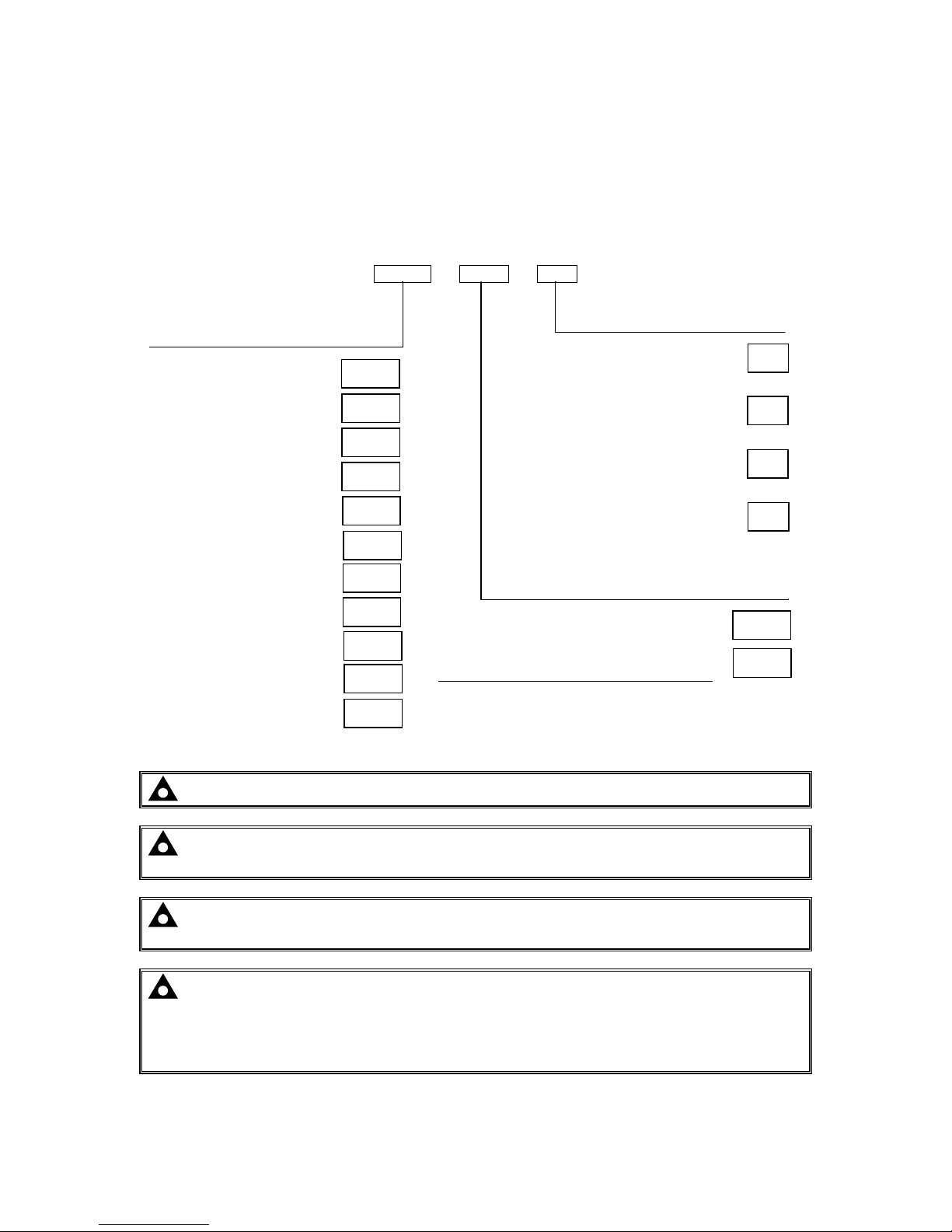
3.1 PART NUMBERING
3.1.1 DSE9000 CHASSIS MOUNT BATTERY CHARGERS
See the following page for details of part numbering of the Industrial / Cabinet mounted battery chargers.
9130 - 001 - 00
NOTE:
NOTE: NOTE:
NOTE: The DSE9150 12V 2A only available in Variant
The DSE9150 12V 2A only available in Variant The DSE9150 12V 2A only available in Variant
The DSE9150 12V 2A only available in Variant ----00 (13.7V for lead acid batteries)
00 (13.7V for lead acid batteries)00 (13.7V for lead acid batteries)
00 (13.7V for lead acid batteries)
NOTE:
NOTE: NOTE:
NOTE: ---- The DSE9250 battery charger is now obsolete, details provided for information
The DSE9250 battery charger is now obsolete, details provided for information The DSE9250 battery charger is now obsolete, details provided for information
The DSE9250 battery charger is now obsolete, details provided for information
only.
only.only.
only.
NOTE:
NOTE:NOTE:
NOTE: The DSE94
The DSE94The DSE94
The DSE9400
0000
00 series
seriesseries
series only available in Variant
only available in Variant only available in Variant
only available in Variant ----00 (
00 (00 (
00 (11113333....5555VVVV////27V
27V27V
27V for lead acid
for lead acid for lead acid
for lead acid
batteries
batteriesbatteries
batteries then temperature compensated as per battery charger configuration
then temperature compensated as per battery charger configurationthen temperature compensated as per battery charger configuration
then temperature compensated as per battery charger configuration))))
NOTE:
NOTE: NOTE:
NOTE: For varian
For varianFor varian
For variant 03 (For other battery types), the float voltage can be adjusted
t 03 (For other battery types), the float voltage can be adjusted t 03 (For other battery types), the float voltage can be adjusted
t 03 (For other battery types), the float voltage can be adjusted
between 12.5V and 15V for DSE9130 12V 5A chargers (25V
between 12.5V and 15V for DSE9130 12V 5A chargers (25V between 12.5V and 15V for DSE9130 12V 5A chargers (25V
between 12.5V and 15V for DSE9130 12V 5A chargers (25V ---- 30V for DSE9250 24V 3.7A
30V for DSE9250 24V 3.7A 30V for DSE9250 24V 3.7A
30V for DSE9250 24V 3.7A
chargers). This change must be made at the DSE factory. Ensure the correct variant (and
chargers). This change must be made at the DSE factory. Ensure the correct variant (and chargers). This change must be made at the DSE factory. Ensure the correct variant (and
chargers). This change must be made at the DSE factory. Ensure the correct variant (and
float voltage if ap
float voltage if apfloat voltage if ap
float voltage if applicable) is specified on ordering. Consult your battery manufacturer for
plicable) is specified on ordering. Consult your battery manufacturer for plicable) is specified on ordering. Consult your battery manufacturer for
plicable) is specified on ordering. Consult your battery manufacturer for
further details of required float voltage.
further details of required float voltage.further details of required float voltage.
further details of required float voltage.
Product type
Variant
Hardware revisions
First version hardware
001
00
For 9 or 18 cell NICAD batteries*
12V charger set to 13.0V
24V charger set to 26.0V
01
For 10 or 20 cell NICAD batteries*
12V charger set to 14.5V
24V charger set to 29.0V
02
For other battery types*
Specify required float voltage on ordering**
03
DSE9130 12V 5A
9130
DSE
9130
•
Internal change to switching
frequency 67kHz)
DSE
9250
•
Internal change to switching
frequency (67kHz)
• AC input range increased to
002
DSE9140 12V 10A
9140
DSE9150 12V 2A
9150
DSE9155 30V 2A
9155
DSE9250 24V 3.7A
9250
DSE9255 24V 5A
9255
DSE9260 24V 10A
9260
DSE9470 24V 10A
9470
For lead acid batteries
12V charger set to 13.7V
24V charger set to 27.4V
DSE9472 24V 5A
9472
DSE9480 24V 10A
9480
DSE9841 24V 5A
9481

Specifications
8
3.1.2 DSE0907 INDUSTRIAL / DSE0908 CABINET MOUNTED BATTERY CHARGERS
See the preceeding page for details of part numbering of chassis mounted battery chargers.
Industrial / Cabinet mounted battery chargers are 9000 series battery chargers factory fitted into wall
mounted enclosures. For details see the section entitled Dimensions and Mounting elsewhere in
this document.
0907-002-02
INDUSTRIAL BATTERY CHARGER 12V 5A 220-250V
0908-001-
11
CABINET MOUNTED BATTERY CHARGER 12V 10A
0908-001-21 CABINET MOUNTED BATTERY CHARGER 24V 10A
0907 - 001 - 00
When ordering Industrial / Cabinet mounted battery chargers, ensure you specify the type of batteries
that are to be charged. If you do not specify this, the chargers will be preset to charge Lead Acid type
batteries.
Product type
Variant
Hardware revisions

Specifications
9
3.2 PROTECTION
3.2.1 DSE9200 SERIES AND DSE9400 SERIES
• Current limit to charger specification (2A, 3.7A, 5A or 10A depending upon charger model)
• Short circuit protection. Charger automatically restarts operation after the fault is removed.
• Reverse battery polarity protection. Charger automatically restarts operation after the fault is
removed.
• Charge failure output
Parameter
Comment
Charge failure determination The charge fail circuit will operate upon failure of the AC input or if
the output voltage drops below approximately 6V
Charge failure relay rating 3A DC resistive, 30V maximum
Specifications
10
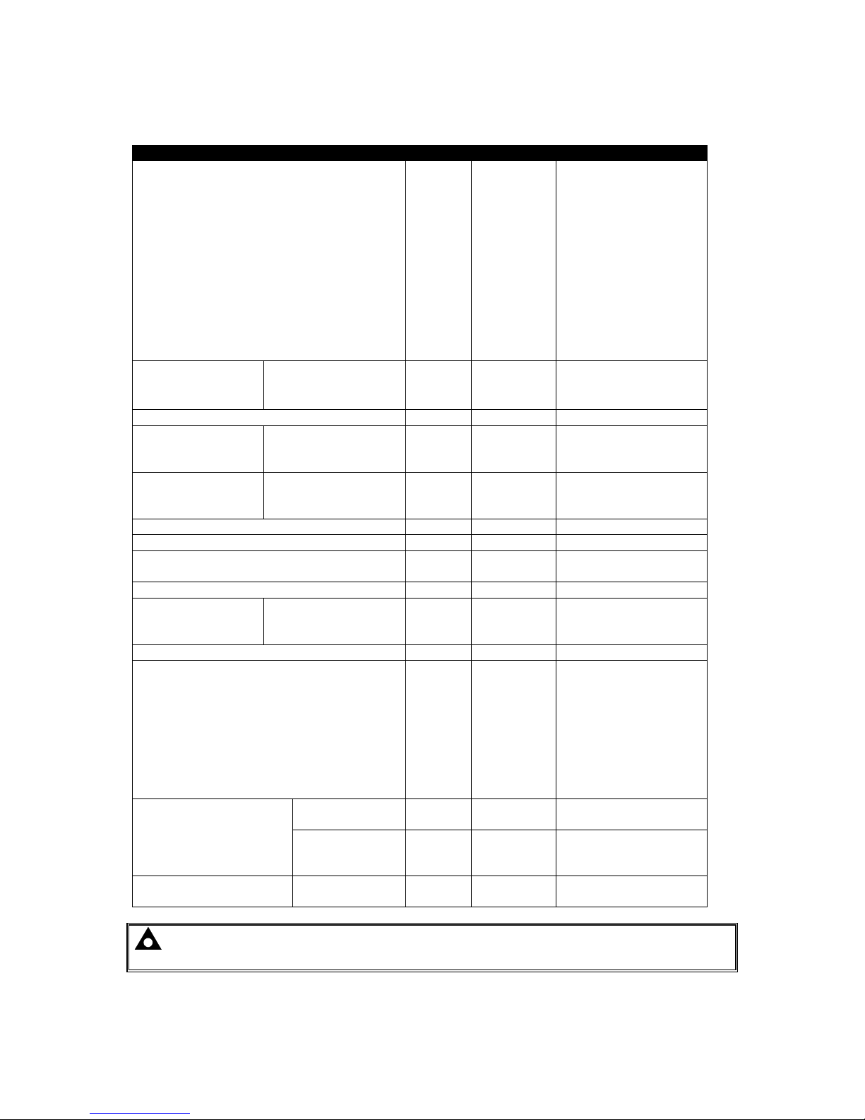
3.3 COMMON ELECTRICAL SPECIFICATIONS
Parameter
Min Nominal
Max
AC
Input Voltage (V)
DSE9130 12V 5A
DSE9150 12V 2A
DSE9140 12V 10A
DSE9155 30V 2A
DSE9250 24V 3.7A (9250-001-xx)
DSE9250 24V 3.7A (9250-002-xx)
DSE9255 24V 5A
DSE9260 24V 10A
DSE9470 24V 10A
DSE9472 24V 5A
DSE9480 12V 10A
DSE9471 12V 5A
90V
90V
90V
85V
90V
90V
90V
90V
95V
95V
95V
95V
110V-277V
110V-240V
110V-240V
110V-240V
110V-240V
110V-277V
110V-277V
110V-277V
110V-277V
110V-277V
110V-277V
110V-277V
304V
250V
277V
265V
265V
305V
305V
305V
305V
305V
305V
305V
Operating
Temperature
DSE9100 Series
DSE9200 Series
DSE9400 Series
-30°C
-30°C
-30°C
55°C
55°C
85°C with de-ratings
Input F
requency (Hz)
48Hz 64Hz
Output Ripple and
Noise
DSE9100 Series
DSE9200 Series
DSE9400 Series
1% Vo
2% Vo
1% Vo
Load Regulation
DSE9100 Series
DSE9200 Series
DSE9400 Series
1% Vo
2% Vo
1% Vo
Line
R
egulation
<0.01% Vo
Output
V
oltage
O
vershoot %
<5%Vo
Transient
Response Peak D
eviation (mV)
(at 50% to 100% load step)
<4% Vo
Warm Up V
oltage (V)
<1% Vo
Output Voltage
Rise Time (ms)
DSE9100 Series
DSE9200 Series
DSE9400 Series
<100ms
<100ms
<200ms
Short Circuit P
rotection
Hiccup
Switching
F
requency (k
Hz)
9130-001-xx (replaced with 9130-002-xx)
9250-001-xx (replaced with 9250-002-xx)
9130-002-xx
9250-002-xx
94xx-xxx-xx
All other chargers
100kHz
100kHz
67kHz
67kHz
67kHz
100kHz
Efficiency %
(See section entitled
‘output specifications’
elsewhere in this
manual)
DSE9100 Series
DSE9200 Series
>80%
DSE9400 Series
>85%
Temperature Sensor
Input
DSE9400 Series PT1000
NOTE:
NOTE: NOTE:
NOTE: Check the
Check theCheck the
Check the DSE9
DSE9DSE9
DSE9444400 Series
00 Series00 Series
00 Series de
dede
de----rating curves which can be found else where in
rating curves which can be found else where in rating curves which can be found else where in
rating curves which can be found else where in
this manual for more information.
this manual for more information.this manual for more information.
this manual for more information.

Specifications
11
Communication
Specification
USB Port
(DSE9400 series
only)
USB2.0 Device for connection to PC running DSE Configuration Suite
Max distance 6m (20 feet)
RS485 Serial
Port
(DSE9400 series
only)
Isolated
Data connection 2 wire + common
Half Duplex
Data direction control for Transmit (by s/w protocol)
Max Baud Rate 19200
External termination required (120Ω)
Max common mode offset 70V (on board protection transorb)
Max distance 1.2km (¾ mile)
Specifications
12
3.4 DSE9470 COMMUNICATION PORT USAGE
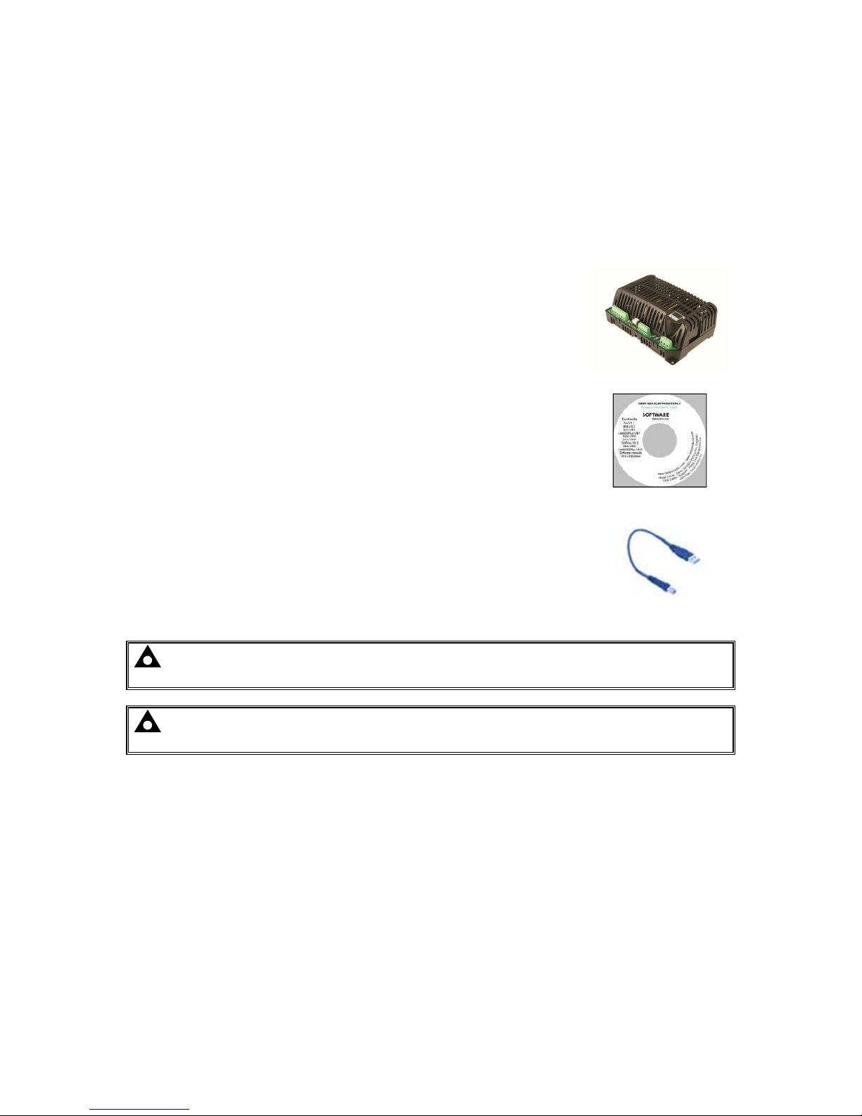
3.4.1 USB CONNECTION
The USB port is provided to give a simple means of connection between a PC and the DSE9400
series battery charger. Using the DSE Configuration Suite Software, the operator is then configure
and monitor the state of the battery charger.
To connect a DSE9400 series battery charger to a PC by USB, the following items are required:
• DSE9400 series battery charger
• DSE Configuration Suite Software
(Supplied on configuration suite software CD or available from
www.deepseaplc.com).
• USB cable Type A to Type B.
(This is the same cable as often used between a PC and a USB
printer)
DSE can supply this cable if required :
PC Configuration interface lead (USB type A – type B) DSE Part
No 016-125
NOTE:
NOTE: NOTE:
NOTE: ---- The DSE
The DSEThe DSE
The DSE9400 series
9400 series9400 series
9400 series battery charger
battery charger battery charger
battery charger must be connect
must be connectmust be connect
must be connected
eded
ed to ONLY the AC supply
to ONLY the AC supply to ONLY the AC supply
to ONLY the AC supply
before configuration or monitoring can begin
before configuration or monitoring can beginbefore configuration or monitoring can begin
before configuration or monitoring can begin....
NOTE:
NOTE: NOTE:
NOTE: ---- Refer to DSE
Refer to DSERefer to DSE
Refer to DSE9400 Series
9400 Series9400 Series
9400 Series Battery Charger
Battery ChargerBattery Charger
Battery Charger PC Software Configuration
PC Software ConfigurationPC Software Configuration
PC Software Configuration Manual for
Manual forManual for
Manual for
further details on configuring and monitoring
further details on configuring and monitoringfurther details on configuring and monitoring
further details on configuring and monitoring....
Specifications
13
3.4.2 RS485
The RS485 port on the DSE9400 series battery chargers support the Modbus RTU protocol.
The DSE Powercomm register table for the controller is available upon request from the DSE
Technical Support Department.
RS485 is used for point-to-point cable connection of more than one device (maximum 32 devices)
and allows for connection to PCs, PLCs and Building Management Systems (to name just a few
devices).
One advantage of the RS485 interface is the large distance specification (1.2km) when using Belden
9841 (or equivalent) cable. This allows for a large distance between the DSE9400 series battery
charger and a PC running the DSE Configuration Suite software. The operator is then able to view the
various operating parameters.
NOTE:
NOTE: NOTE:
NOTE: ---- For distances up to 6m (8yds) the USB connection method is mor
For distances up to 6m (8yds) the USB connection method is morFor distances up to 6m (8yds) the USB connection method is mor
For distances up to 6m (8yds) the USB connection method is more suitable and
e suitable and e suitable and
e suitable and
provides for a lower cost alternative to RS485 (which is more suited to longer distance
provides for a lower cost alternative to RS485 (which is more suited to longer distance provides for a lower cost alternative to RS485 (which is more suited to longer distance
provides for a lower cost alternative to RS485 (which is more suited to longer distance
connections).
connections).connections).
connections).
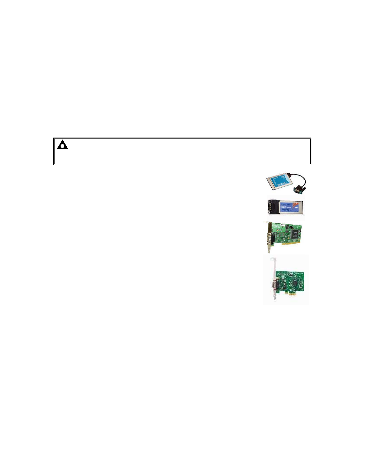
• Brainboxes PM154 PCMCIA RS485 card (for laptops PCs)
Set to ‘Half Duplex, Autogating” with ‘CTS True’ set to ‘enabled’
• Brainboxes VX-023 ExpressCard 1 Port RS422/485 (for laptops and
nettop PCs)
• Brainboxes UC320 PCI Velocity RS485 card (for desktop PCs)
Set to ‘Half Duplex, Autogating” with ‘CTS True’ set to ‘enabled’
• Brainboxes PX-324 PCI Express 1 Port RS422/485 (for desktop PCs)
Supplier:
Brainboxes
Tel: +44 (0)151 220 2500
Web: http://www.brainboxes.com
Email: Sales: sales@brainboxes.com

Specifications
14
3.6 OUTPUT SPECIFICATIONS
3.6.1 DSE9130 12V 5A
Parameter
Min Nominal
Max Comments
Output Voltage (12 V DC battery) 12.5V 13.7V 15.0V Specify float voltage on ordering.
Output Charging Current (A) 0A 5A 5.5A
Current limit threshold (A) 5A 5.3A 5.5A
Recovery from current limit (A) 5A
Full load AC input current (A) 1.5A With output at 13.7V DC
AC Input Inrush (10ms) current (A) 20A
0.8
0.82
0.84
0.86
0.88
0.9
0.92
85 110 230 260
Efficiency (%)
Input Voltage (V)
DSE9130 Efficiency Curve at 5A

Specifications
15
3.6.2 DSE9140 12V 10A
Parameter
Min Nominal
Max Comments
Output Voltage (12 V DC Battery) 12V 13.7V 15V
Output Charging Current (A) 10A 10A 11A
Current limit threshold (A) 10A 11A
Recovery from current limit (A) 10A 11A
Full load AC input current (A) 3.1A At Vin=85V, Vo=13.7V, Io=10Amp
Full load AC input current (A) 1.3A At Vin=230V, Vo=13.7V Io=10Amp
AC Input Inrush (10ms) current (A) 60A
0.78
0.79
0.8
0.81
0.82
0.83
0.84
0.85
0.86
0.87
85
110
230
260
Efficiency (%)
Input Voltage (V)
DSE9140 Efficiency Curve at 10A

Specifications
16
3.6.3 DSE9150 12V 2A
Parameter
Min Nominal
Max Comments
Output Voltage (12 V DC Battery) 12.5V 13.7V 13.7V Float voltage not adjustable
Output Charging Current (A) 0A 2A 2.5A
Current limit threshold (A) 2A 2.3A 2.5A
Recovery from current limit (A) 2A
Full load AC input current (A) 0.7A With output at 13.7V DC
AC Input Inrush (10ms) current (A) 10A
74
76
78
80
82
84
86
88
90
85
110
230
250
Efficiency (%)
Input Voltage (V)
DSE9150 Efficiency Curve at 2A

Specifications
17
3.6.4 DSE9155 30V 2A
Parameter
Min Nominal
Max Comments
Output Voltage (30 V DC Battery) 28.0V 34.3V 34.5
Output Charging Current (A) 0A 2.2A 3A
Current limit threshold (A) 2A 2.2A 3A
Recovery from current limit (A) 2A
Full load AC input current (A) 2A
AC Input Inrush (10ms) current (A) 30A
0.78
0.8
0.82
0.84
0.86
0.88
0.9
0.92
0.94
85 110 230 260
Efficiency (%)
Input Voltage (V)
DSE9155 Efficiency Curve at 2A
 Loading...