

Page 1

DSE7410 & DSE7420 Operator Manual ISSUE: 2
DEEP SEA ELECTRONICS PLC
DSE7410 & DSE7420 Operator Manual
Document Number: 057-161
Author: Ashley Senior
Page 2
DSE7410 & DSE7420 Operator Manual
2
DEEP SEA ELECTRONICS PLC
Highfield House
Hunmanby
North Yorkshire
YO14 0PH
ENGLAND
Sales Tel: +44 (0) 1723 890099
Sales Fax: +44 (0) 1723 893303
E-mail : [email protected]
Website : www.deepseaplc.com
DSE7410 & DSE7420 Operator Manual
© Deep Sea Electronics Plc
All rights reserved. No part of this publication may be reproduced in any material form (including
photocopying or storing in any medium by electronic means or other) without the written permission
of the copyright holder except in accordance with the prov isions of the Copyright, Designs and
Patents Act 1988.
Applications for the copyright holder’s written permission to reproduce any part of this publication
should be addressed to Deep Sea Electronics Plc at the address above.
The DSE logo is a UK registered trademarks of Deep Sea Electronics PLC.
Any reference to trademarked product names used within this publication is owned by their respective
companies.
Deep Sea Electronics Plc reserves the right to change the contents of this document without prior
notice.
Amendments List
Issue Comments Minimum
Module version
required
Minimum
Configuration Suite
Version required
1 Initial release V1.0.0 2011.10v1.0.7
1.1 Amended fault in DSE7410 Diagram
2 Added wiring information for CT Location. V1.3 2015.21 V1.251.2
Typeface: The typeface used in this document is Arial. Care should be taken not to mistake the upper case letter I with the numeral 1. T he numeral
1 has a top serif to avoid this confusion.
Clarification of notation used within this publication.
NOTE:
Highlights an essential element of a procedure to ensure correctness.
CAUTION!
Indicates a procedure or practice, which, if not strictly observed, could result in
damage or destruction of equipment.
WARNING!
Indicates a procedure or practice, which could result in injury to personnel or loss
of life if not followed correctly.
Page 3

DSE7410 & DSE7420 Operator Manual
3
TABLE OF CONTENTS
Section Page
1 BIBLIOGRAPHY............................................................................................... 7
1.1 INSTALLATION INSTRUCTIONS ................................................................................... 7
1.2 TRAINING GUIDES......................................................................................................... 7
1.3 MANUALS ....................................................................................................................... 7
1.4 THIRD PARTY DOCUMENTS ......................................................................................... 7
2 INTRODUCTION .............................................................................................. 8
3 SPECIFICATIONS ............................................................................................ 9
3.1 SHORT NAMES .............................................................................................................. 9
3.2 TERMINAL SPECIFICATION .......................................................................................... 9
3.3 POWER SUPPLY REQUIREMENTS .............................................................................. 9
3.4 GENERATOR VOLTAGE / FREQUENCY SENSING .................................................... 10
3.5 GENERATOR CURRENT SENSING ............................................................................. 11
3.5.1 VA RATING OF THE CTS ...................................................................................... 11
3.5.2 CT POLARITY ........................................................................................................ 12
3.5.3 CT PHASING.......................................................................................................... 12
3.5.4 CT CLASS .............................................................................................................. 12
3.6 INPUTS ......................................................................................................................... 13
3.6.1 DIGITAL INPUTS ................................................................................................... 13
3.6.2 ANALOGUE INPUTS .............................................................................................. 13
3.6.2.1 OIL PRESSURE .............................................................................................. 13
3.6.2.2 COOLANT TEMPERATURE ............................................................................ 13
3.6.2.3 FUEL LEVEL ................................................................................................... 13
3.6.2.4 FLEXIBLE SENSOR ........................................................................................ 14
3.6.3 CHARGE FAIL INPUT ............................................................................................ 14
3.6.4 MAGNETIC PICKUP .............................................................................................. 14
3.7 OUTPUTS ..................................................................................................................... 15
3.7.1 OUTPUTS A & B .................................................................................................... 15
3.7.2 CONFIGURABLE OUTPUTS C & D (LOAD SWITCHING) ..................................... 15
3.7.2.1 CONTACTOR COILS ...................................................................................... 1 5
3.7.2.2 UNDERVOLTAGE (UV COILS) ....................................................................... 15
3.7.2.3 CLOSING COILS ............................................................................................. 16
3.7.2.4 OPENING COILS / SHUNT TRIP COILS ......................................................... 16
3.7.3 OUTPUTS E,F,G,H, I & J ....................................................................................... 16
3.8 COMMUNICATION PORTS .......................................................................................... 17
3.9 COMMUNICATION PORT USAGE .............................................................................. 17
3.9.1 CAN INTERFACE .................................................................................................. 17
3.9.2 USB CONNECTION ............................................................................................... 18
3.9.3 USB HOST-MASTER (USB DRIVE CONNECTION) ............................................... 18
3.9.4 RS232 .................................................................................................................... 19
3.9.4.1 RECOMMENDED PC RS232 SERIAL PORT ADD-ONS ................................. 19
3.9.4.2 RECOMMENDED EXTERNAL MODEMS: ....................................................... 20
3.9.5 RS485 .................................................................................................................... 21
3.9.5.1 RECOMMENDED PC RS485 SERIAL PORT ADD-ONS ................................. 21
3.9.6 ETHERNET ............................................................................................................ 22
3.9.6.1 DIRECT PC CONNECTION ............................................................................. 22
3.9.6.2 CONNECTION TO BASIC ETHERNET ........................................................... 23
3.9.6.3 CONNECTION TO COMPANY INFRASTRUCTURE ETHERNET ................... 24
3.9.6.4 CONNECTION TO THE INTERNET ................................................................ 25
3.9.6.5 FIREWALL CONFIGURATION FOR INTERNET ACCESS .............................. 27
3.10 DSENET® FOR EXPANSION MODULES ................................................................ 28
3.10.1 DSENET® USED FOR MODBUS ENGINE CONNECTION .................................... 28
3.11 SOUNDER ................................................................................................................. 29
3.11.1 ADDING AN EXTERNAL SOUNDER TO THE APPLICATION ................................ 29
Page 4

DSE7410 & DSE7420 Operator Manual
4
3.12 ACCUMULATED INSTRUMENT AT IO N . .. .. ............................................................... 29
3.13 DIMENSIONS AND MOUNTING ................................................................................ 30
3.13.1 DIMENSIONS ......................................................................................................... 30
3.13.2 PANEL CUTOUT .................................................................................................... 30
3.13.3 WEIGHT ................................................................................................................. 30
3.13.4 FIXING CLIPS ........................................................................................................ 31
3.13.5 CABLE TIE FIXING POINTS .................................................................................. 32
3.13.6 SILICON SEALING GASKET.................................................................................. 32
3.14 APPL ICABLE STANDARDS............ .. .. .. .. .................................................................. 33
3.14.1 ENCLOSURE CLASSIFICATIONS ......................................................................... 35
3.14.2 NEMA CLASSIFICATIONS ..................................................................................... 36
4 INSTALLATION.............................................................................................. 37
4.1 TERMINAL DESCRIPTION ........................................................................................... 37
4.1.1 DC SUPPLY, FUEL AND START OUTPUTS, OUTPUTS E-J ................................. 38
4.1.2 ANALOGUE SENSOR ............................................................................................ 39
4.1.3 MAGNETIC PICKUP, CAN AND EXPANSION ....................................................... 40
4.1.4 LOAD SWITCHING AND V1 GENERATOR VOLTAGE SENSING ......................... 41
4.1.5 V2 BUS/MAINS VOLTAGE SENSING .................................................................... 41
4.1.6 GENERATOR CURRENT TRANSFORMERS ........................................................ 42
4.1.7 CONFIGURABLE DIGITAL INPUTS ....................................................................... 44
4.1.8 PC CONFIGURATION INTERFACE CONNECTOR ............................................... 44
4.1.9 RS485 CONNECTOR ............................................................................................. 45
4.1.10 RS232 CONNECTOR ............................................................................................. 45
4.2 TYPICAL WIRING DIAGRAMS ..................................................................................... 46
4.2.1 DSE7410 3 PHASE, 4 WIRE W ITH RESTRICTED EARTH FAULT PROTECTION 47
4.2.2 DSE7420 3 PHASE, 4 WIRE W ITH RESTRICTED EARTH FAULT PROTECTION 48
4.3 ALT ERNATIVE T OPOLOGIES ..................................................................................... 49
4.3.1 3 PHASE, 4 WIRE WITHOUT EARTH FAULT PROTECTION ............................... 49
4.3.2 SINGLE PHASE WITH RESTRICTED EARTH FAULT ........................................... 50
4.3.3 SINGLE PHASE WITHOUT EARTH FAULT ........................................................... 50
4.3.4 2 PHASE (L1 & L2) 3 WIRE WITH RESTRICTED EARTH FAULT ......................... 51
4.3.5 2 PHASE (L1 & L2) 3 WIRE WITHOUT EARTH FAULT ......................................... 51
4.3.6 2 PHASE (L1 & L3) 3 WIRE WITH RESTRICTED EARTH FAULT ......................... 52
4.3.7 2 PHASE (L1 & L3) 3 WIRE WITHOUT EARTH FAULT MEASURING ................... 52
4.3.8 3 PHASE 4 WIRE WITH UNRESTRICTED EARTH FAULT MEASURING ............. 53
4.3.9 CT LOCATION ....................................................................................................... 54
4.4 EARTH SYSTEMS ........................................................................................................ 56
4.4.1 NEGATIVE EARTH ................................................................................................ 56
4.4.2 POSITIVE EARTH .................................................................................................. 56
4.4.3 FLOATING EARTH................................................................................................. 56
4.5 TYPICAL ARRANGEMENT OF DSENET® ................................................................... 56
5 DESCRIPTION OF CONTROLS .................................................................... 58
5.1 DSE7410 AUTO START CONTROL MODULE ............................................................. 58
5.2 DSE7420 AUTO START CONTROL MODULE ............................................................. 59
5.3 QUICKSTART GUIDE ................................................................................................... 60
5.3.1 STARTING THE ENGINE ....................................................................................... 60
5.3.2 STOPPING THE ENGINE ...................................................................................... 60
5.4 VIEWING THE INSTRUMENT PAGES ......................................................................... 6 1
5.4.1 STATUS ................................................................................................................. 62
5.4.2 ENGINE.................................................................................................................. 63
5.4.3 GENERATOR ......................................................................................................... 64
5.4.4 BUS (DSE7410 ONLY) ........................................................................................... 64
5.4.5 MAINS (DSE7420 ONLY) ....................................................................................... 64
5.4.6 RS232 SERIAL PORT ............................................................................................ 65
5.4.7 RS485 SERIAL PORT ............................................................................................ 68
5.4.8 ABOUT ................................................................................................................... 69
5.4.8.1 ETHERNET PAGES ........................................................................................ 70
5.4.8.2 DATA LOGGING PAGES ................................................................................ 71
Page 5

DSE7410 & DSE7420 Operator Manual
5
5.4.9 CAN ERROR MESSAGES ..................................................................................... 72
5.5 VIEWING THE EVENT LOG ......................................................................................... 73
5.6 USER CONFIGURABLE INDICATORS ........................................................................ 74
6 OPERATION................................................................................................... 75
6.1 CONTROL .................................................................................................................... 75
6.2 CONTROL PUSH-BUTTONS........................................................................................ 76
6.3 ALTERNATIVE CONFIGURATIONS ............................................................................ 77
6.4 DUMMY LOAD / LOAD SHEDDING CONTROL ........................................................... 78
6.5 STOP MODE ................................................................................................................. 79
6.5.1 ECU OVERRIDE .................................................................................................... 80
6.6 MANUAL MODE ........................................................................................................... 81
6.6.1 WAITING IN MANUAL MODE ................................................................................ 81
6.6.2 STARTING SEQUENCE ......................................................................................... 81
6.6.3 ENGINE RUNNING ................................................................................................ 82
6.6.4 MANUAL FUEL PUMP CONTROL ......................................................................... 82
6.6.5 MANUAL SPEED CONTROL.................................................................................. 8 2
6.6.6 STOPPING SEQUENCE ........................................................................................ 83
6.7 TEST MODE ................................................................................................................. 83
6.7.1 WAITING IN TEST MODE ...................................................................................... 83
6.7.2 STARTING SEQUENCE ......................................................................................... 83
6.7.3 ENGINE RUNNING ................................................................................................ 84
6.8 AUTOMATIC MODE ..................................................................................................... 85
6.8.1 WAITING IN AUTO MODE ..................................................................................... 85
6.8.2 STARTING SEQUENCE ......................................................................................... 85
6.8.3 ENGINE RUNNING ................................................................................................ 86
6.8.4 STOPPING SEQUENCE ........................................................................................ 86
7 PROTECTIONS .............................................................................................. 87
7.1 PROTECTIONS DISABLED .......................................................................................... 88
7.1.1 INDICATION / WARNING ALARMS ....................................................................... 88
7.1.2 SHUTDOWN / ELECTRICAL TRIP ALARMS ......................................................... 88
7.1.3 CAN ALARMS ........................................................................................................ 89
7.2 INDICATIONS ............................................................................................................... 90
7.3 WARNINGS ................................................................................................................... 91
7.4 HIGH CURRENT WARNING ALARM ............................................................................ 92
7.5 SHUTDOWNS ............................................................................................................... 93
7.6 ELECTRICAL TRIPS .................................................................................................... 95
7.7 HIGH CURRENT SHUTDOWN / ELECTRICAL TRIP ALARM ...................................... 96
7.7.1 IMMEDIATE WARNING ......................................................................................... 96
7.7.2 IDMT ALARM ......................................................................................................... 96
7.8 EARTH FAULT SHUTDOWN / ELECTRICAL TRIP ALARM ........................................ 99
7.9 SHORT CIRCUIT ALARM ........................................................................................... 100
7.10 MAINTENANCE ALARM ......................................................................................... 101
8 SCHEDULER................................................................................................ 102
8.1.1 STOP MODE ........................................................................................................ 102
8.1.2 MANUAL MODE ................................................................................................... 102
8.1.3 AUTO MODE ........................................................................................................ 102
9 FRONT PANEL CONFIGURATION ............................................................. 103
9.1 ACCESSING THE MAIN FRONT PANEL CONFIGURATION EDITOR ...................... 104
9.1.1 EDITING A PARAMETER ..................................................................................... 105
9.2 ADJUSTABLE PARAMETERS ................................................................................... 106
9.3 ACCESSING THE ‘RUNNING’ CONFIGURAT ION EDITOR ....................................... 107
9.3.1 EDITING A PARAMETER ..................................................................................... 107
9.3.2 ADJUSTABLE PARAMETERS (RUNNING EDITOR)............................................ 107
10 COMMISSIONING ..................................................................................... 108
10.1 PRE-COMMISSIONING ........................................................................................... 108
Page 6

DSE7410 & DSE7420 Operator Manual
6
11 FAULT FINDING ....................................................................................... 109
11.1 STARTING .............................................................................................................. 109
11.2 LOADING ................................................................................................................ 109
11.3 ALARMS .................................................................................................................. 110
11.4 COMMUNICATIONS ................................................................................................ 111
11.5 INSTRUMENTS ....................................................................................................... 112
11.6 MISCELLANEOUS .................................................................................................. 112
12 MAINTENANCE, SPARES, REPAIR AND SERVICING ............................ 113
12.1 PURCHASING ADDITIONAL CONNECTOR PLUGS FROM DSE .......................... 113
12.1.1 PACK OF PLUGS ................................................................................................. 113
12.1.2 INDIVIDUAL PLUGS............................................................................................. 113
12.2 PURCHASING ADDITIONAL FIXING CLIPS FROM DSE ....................................... 113
12.3 PURCHASING ADDITIONAL SEALING GASKET FROM DSE ............................... 113
12.4 DSENET EXPANSION MODULES .......................................................................... 114
13 WARRANTY .............................................................................................. 117
14 DISPOSAL ................................................................................................. 117
14.1 WEEE (WASTE ELECTRICAL AND ELECTRONIC EQUIPMENT) ......................... 117
14.2 ROHS (RESTRICTION OF HAZARDOUS SUBSTANCES) ..................................... 117
Page 7
Bibliography
7
1 BIBLIOGRAPHY
This document refers to and is referred to by the following DSE publications which can be obtained
from the DSE website: www.deepseaplc.com
1.1 INSTALLATION INSTRUCTIONS
Installation instructions are supplied with the product in the box and are intended as a ‘quick start’
guide only.
DSE PART DESCRIPTION
053-085 DSE7410 Installation Instructions
053-088 DSE7420 Installation Instructions
053-032 DSE2548 LED Expansion Annunciator Installation Instructions
053-033 DSE2130 Input Expansion Installation Instructions
053-034 DSE2157 Output Expansion Installation Instructions
053-125 DSE2131 Ratio-metric Input Expansion Installation Instructions
053-126 DSE2133 RTD/Thermocouple Input Expansion Installation Instructions
053-134 DSE2152 Ratio-metric Output Expansion Installation Instructions
1.2 TRAINING GUIDES
Training Guides are produced to give ‘handout’ sheets on specific subjects during training sessions
DSE PART DESCRIPTION
056-005 Using CTs With DSE Products
056-010 Overcurrent Protection
056-018 Negative Phase Sequence
056-019 Earth Fault Protection
056-020 Loss of Excitation
056-022 Breaker Control
056-024 GSM Modem
056-026 kW & kVAr
056-029 Smoke Limiting
056-030 Module PIN Codes
1.3 MANUALS
Product manuals are can be downloaded from the DSE website: www.deepseaplc.com
DSE PART DESCRIPTION
057-004 Electronic Engines and DSE Wiring
057-160 DSE7400 Series Configuration Software Manual
057-082 DSE2130 Input Expansion Manual
057-083 DSE2157 Output Expansion Manual
057-084 DSE2548 Annunciator Expansion Manual
057-139 DSE2131 Ratio-metric Input Expansion Manual
057-140 DSE2133 RTD/Thermocouple Expansion Manual
057-141 DSE2152 Ratio-metric Output Expansion Manual
1.4 THIRD PARTY DOCUMENTS
The following third party documents are also referred to:
REFERENCE DESCRIPTION
ISBN 1-55937-879-4 IEEE Std C37.2-1996 IEEE Standard Electrical Power System Device Function
Numbers and Contact Designations. Institute of Electrical and Electronics Engineers
Inc
ISBN 0-7506-1147-2 Diesel generator handbook. L.L.J.Mahon
ISBN 0-9625949-3-8 On-Site Power Generation. EGSA Education Committee.
Page 8

Introduction
8
2 INTRODUCTION
This document details the installation and operation requirements of the DSE7400 Series modules,
part of the
DSEGenset® range of products.
The manual forms part of the product and should be kept for the entire life of the product. If the
product is passed or supplied to another party, ensure that this document is passed to them for
reference purposes.
This is not a controlled document. You will not be automatically informed of updates. Any future
updates of this document will be included on the DSE website at www.deepseaplc.com
The DSE7400 series is designed to provide differing levels of functionality across a common
platform. This allows the generator OEM greater flexibility in the choice of controller to use for a
specific application.
The DSE7400 series module has been designed to allow the operator to start and stop the generator,
and if required, transfer the load to the generator either manually (via fascia mounted push-buttons)
or automatically. Additionally, the DSE7420 automatically starts and stops the generator set
depending upon the status of the mains (utility) supply.
The user also has the facility to view the system operating parameters via the LCD display.
The DSE7400 module monitors the engine, indicating the operational status and fault conditions,
automatically shutting down the engine and giving a true first up fault condition of an engine failure by
a COMMON AUDIBLE ALARM. The LCD display indicates the fault.
The powerful ARM microprocessor contained within the module allows for incorporation of a range of
complex features:
• Text based LCD display (supporting multiple languages).
• True RMS Voltage, Current and Power monitoring.
• Communications capability (RS485, RS232 or Ethernet)
• Engine parameter monitoring.
• Fully configurable inputs for use as alarms or a range of different functions.
• Engine ECU interface to electronic engines.
Using a PC and the DSE Configuration Suite software allows alteration of selected operational
sequences, timers, alarms and operational sequences. Additionally, the module’s integral fascia
configuration editor allows adjustment of a subset of this information.
A robust plastic case designed for front panel mounting houses the module. Connections are via
locking plug and sockets..
Access to critical operational sequences and timers for use by qualified engineers, can be protected
by a security code. Module access can also be protected by PIN code. Selected parameters can be
changed from the module’s front panel.
The module is housed in a robust plastic case suitable for panel mounting. Connections to the
module are via locking plug and sockets.
Page 9
Specification
9
3 SPECIFICATIONS
3.1 SHORT NAMES
Short name Description
DSE7000,DSE7xxx All modules in the DSE7000 range.
DSE7400,DSE74xx All modules in the DSE7400 range.
DSE7410 DSE7410 module/controller
DSE7420 DSE7420 module/controller
3.2 TERMINAL SPECIFICATION
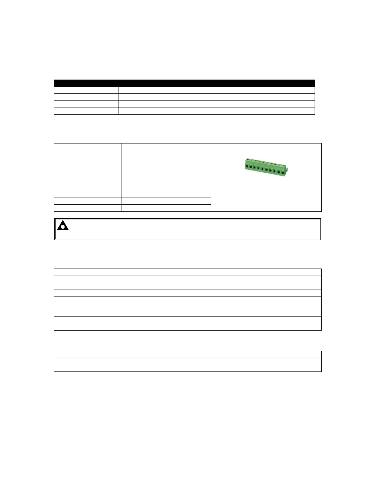
Connection type Two part connector.
• Male part fitted to
module
• Female part supplied in
module packing case Screw terminal, rising
clamp, no internal
spring.
Example showing cable entry and screw
terminals of a 10 way connector
Minimum cable size 0.5mm² (AWG 24)
Maximum cable size 2.5mm² (AWG 10)
NOTE: - For purchasing additional connector plugs from DSE, please see the section
entitled Maintenance, Spares, Repair and Servicing elsewhere in this document.
3.3 POWER SUPPLY REQUIREMENTS
Minimum supply voltage 8V continuous
Cranking dropouts
Able to survive 0V for 50mS providing the supply was at least 10V
before the dropout and recovers to 5V afterwards.
Maximum supply voltage 35V continuous (60V protection)
Reverse polarity protection -35V continuous
Maximum operating current
130mA at 24V
260mA at 12V
Maximum standby current
65mA at 24V
120mA at 12V
Plant supply instrumentation display
Range 0V-70V DC (note Maximum continuous operating voltage of 35V DC)
Resolution 0.1V
Accuracy 1% full scale (±0.7V)
Page 10

Specification
10
3.4 GENERATOR VOLTAGE / FREQUENCY SENSING
Measurement type True RMS conversion
Sample Rate 5KHz or better
Harmonics Up to 10th or better
Input Impedance
300K Ω ph-N
Phase to Neutral 15V
(minimum required for sensing frequency
)
to 333V AC
(absolute maximum)
Suitable for 110V to 277V nominal
(±20% for under/overvoltage detection)
Phase to Phase 26V
(minimum required for sensing frequency
)
to 576V AC
(absolute maximum)
Suitable for 190V ph-ph to 479V ph-ph nominal
(±20% for under/overvoltage detection)
Common mode offset from
Earth
100V AC (max)
Resolution 1V AC phase to neutral
2V AC phase to phase
Accuracy ±1% of full scale phase to neutral
±2% of full scale phase to phase
Minimum frequency 3.5Hz
Maximum frequency 75.0Hz
Frequency resolution 0.1Hz
Frequency accuracy ±0.2Hz
Page 11
Specification
11
3.5 GENERATOR CURRENT SENSING
Measurement type True RMS conversion
Sample Rate 5KHz or better
Harmonics Up to 10th or better
Nominal CT secondary rating 1A or 5A (5A recommended)
Maximum continuous current 5A
Overload Measurement 3 x Nominal Range setting
Absolute maximum overload 50A for 1 second
Burden
0.5VA (0.02Ω current shunts)
common mode offset ±2V peak plant ground to CT common terminal
Resolution 0.5% of 5A
Accuracy ±1% of Nominal (1A or 5A) (excluding CT error)
3.5.1 VA RATING OF THE CTS
The VA burden of the module on the CTs is 0.5VA. However depending upon the type and length of
cabling between the CTs and the module, CTs with a greater VA rating than the module are required.
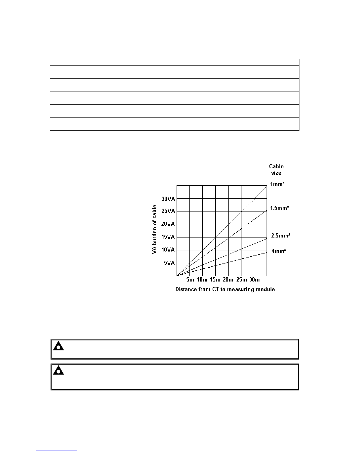
The distance between the CTs and the
measuring module should be
estimated and cross-referenced
against the chart opposite to find the
VA burden of the cable itself.
If the CTs are fitted within the
alternator top box, the star point
(common) of the CTs should be
connected to system ground (earth) as
close as possible to the CTs. This
minimises the length of cable used to
connect the CTs to the DSE module.
Example.
If 1.5mm² cable is used and the
distance from the CT to the measurin
g
module is 20m, then the burden of the
cable alone is approximately 15VA. As
the burden of the DSE controller is
0.5VA, then a CT with a rating of at
least 15+0.5V = 15.5VA must be used.
If 2.5mm² cables are used over the
same distance of 20m, then the
burden of the cable on the CT is
approximately 7VA. CT’s required in
this instance is at least 7.5VA (7+0.5).
NOTE: - Details for 4mm² cables are shown for reference only. The connectors on the DSE
modules are only suitable for cables up to 2.5mm².
NOTE: - CTs with 5A secondary windings are recommended with DSE modules. 1A CTs
can be used if necessary however, the resolution of the readings is 5 times better when using
5A CTs.
Page 12
Specification
12
3.5.2 CT POLARITY
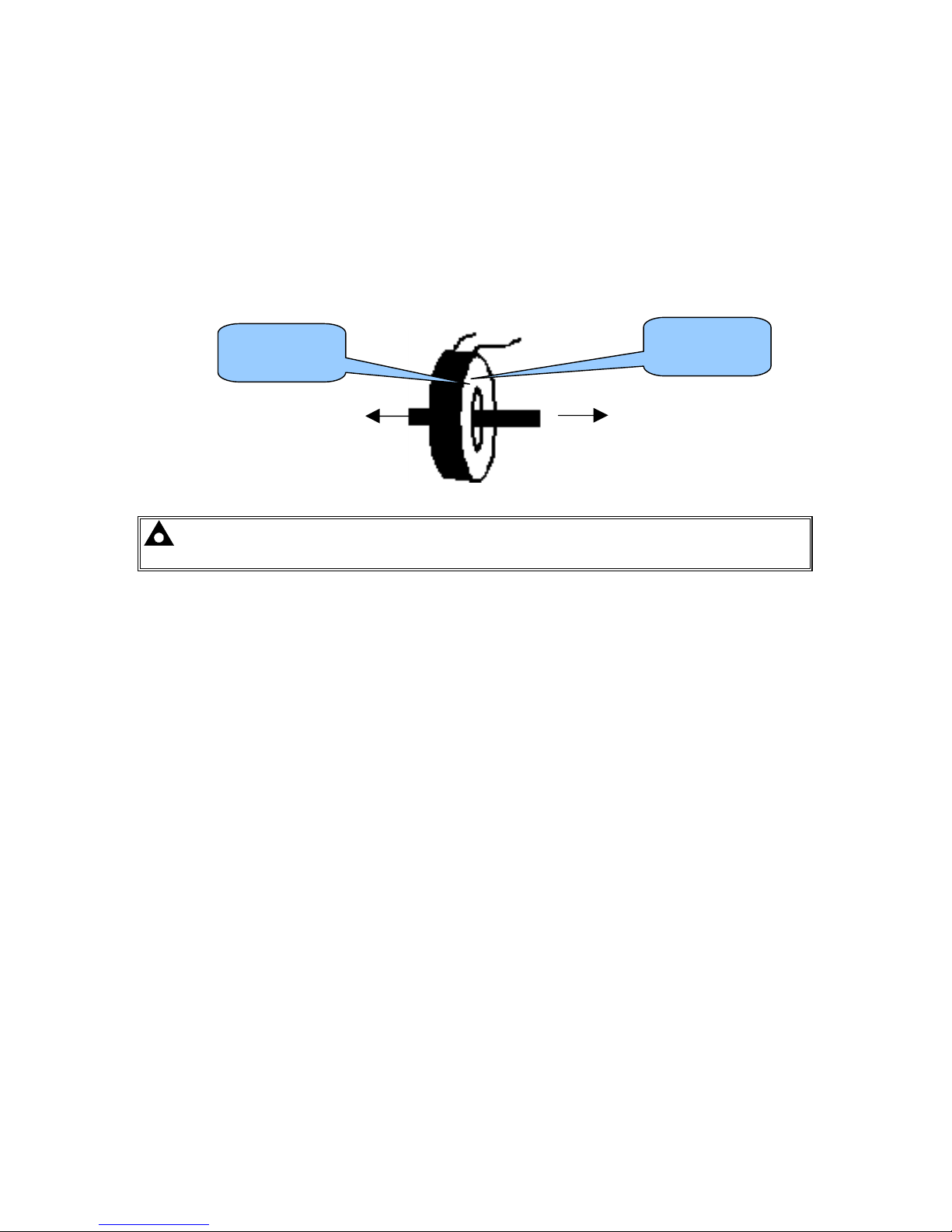
Take care to ensure the correct polarity of the CTs. Incorrect CT orientation will lead to negative kW
readings when the set is supplying power. Take note that paper stick-on labels on CTs that show the
orientation are often incorrectly placed on the CT (!). It is more reliable to use the labelling in the case
moulding as an indicator to orientation (if available).
To test orientation, run the generator in island mode (not in parallel with any other supply) and load
the generator to around 10% of the set rating. Ensure the DSE module shows positive kW for all
three individual phase readings.
TO GENERATOR
TO LOAD SWITCH DEVICE
POLARITY OF CT PRIMARY
NOTE:- Take care to ensure correct polarity of the CT primary as shown above. If in
doubt, check with the CT supplier.
3.5.3 CT PHASING
Take particular care that the CTs are connected to the correct phases. For instance, ensure that the
CT on phase 1 is connected to the terminal on the DSE module intended for connection to the CT for
phase 1.
Additionally ensure that the voltage sensing for phase 1 is actually connected to generator phase 1.
Incorrect connection of the phases as described above will result in incorrect power factor (pf)
measurements, which in turn results in incorrect kW measurements.
One way to check for this is to make use of a single-phase load. Place the load on each phase in
turn, run the generator and ensure the kW value appears in the correct phase. For instance if the load
is connected to phase 3, ensure the kW figure appears in phase 3 display and not in the display for
phase 1 or 2.
3.5.4 CT CLASS
Ensure the correct CT type is chosen. For instance if the DSE module is providing overcurrent
protection, ensure the CT is capable of measuring the overload lev el you wish to protect against, and
at the accuracy lev el you require.
For instance, this may mean fitting a protection class CT (P10 type) to maintain high accuracy while
the CT is measuring overload currents.
Conversely, if the DSE module is using the CT for instrumentation only (current protection is disabled
or not fitted to the controller), then measurement class CTs can be used. Again, bear in mind the
accuracy you require. The DSE module is accurate to better than 1% of the full-scale current reading.
To maintain this accuracy you should fit Class 0.5 or Class 1 CTs.
You should check with your CT manufacturer for further advice on selecting your CTs
labelled as p1,
k
or K
labelled as p2,
l
or L
Page 13

Specification
13
3.6 INPUTS
3.6.1 DIGITAL INPUTS
Number 11 configurable inputs
Arrangement Contact between terminal and ground
Low level threshold 2.1V minimum
High level threshold 6.6V maximum
Maximum input voltage +50V DC with respect to plant supply negative
Minimum input voltage -24V DC with respect to plant supply negative
Contact wetting current 7mA typical
Open circuit voltage 12V typical
3.6.2 ANALOGUE INPUTS
3.6.2.1 OIL PRESSURE
Configurable if engine ECU link provides oil pressure measurement
Measurement type Resistance measurement by measuring voltage across sensor
with a fixed current applied
Arrangement Differential resistance measurement input
Measurement current 15mA
Full scale
240Ω
Over range / fail
270Ω
Resolution 0.1 Bar (1-2 PSI)
Accuracy
±2% of full scale resistance (±4.8Ω) excluding transducer error
Max common mode voltage ±2V
Display range 13.7 bar (0-200 PSI) subject to limits of the sensor
3.6.2.2 COOLANT TEMPERATURE
Configurable if engine ECU link provides coolant temp measurement
Measurement type Resistance measurement by measuring voltage across sensor with a fixed
current applied
Arrangement Differential resistance measurement input
Measurement
current
10mA
Full scale
480Ω
Over range / fail
540Ω
Resolution
1°C (2°F)
Accuracy
+/-2% of full scale resistance (±9.6Ω) excluding transducer error
Max common
mode voltage
±2V
Display range
0°C -140°C (32°F - 284°F) subject to limits of the sensor
3.6.2.3 FUEL LEVEL
Measurement type Resistance measurement by measuring voltage across sensor with a fixed
current applied
Arrangement Differential resistance measurement input
Measurement
current
10mA
Full scale
480Ω
Over range / fail
540Ω
Resolution
1°C (2°F)
Accuracy
+/-2% of full scale resistance (±9.6Ω) excluding transducer error
Max common
mode voltage
±2V
Display range 0-250%
Page 14
Specification
14
3.6.2.4 FLEXIBLE SENSOR
Number 2
Measurement type Resistance measurement by measuring voltage across sensor with a
fixed current applied
Arrangement Differential resistance measurement input
Measurement current 10mA
Full scale
480Ω
Over range / fail
540Ω
Resolution 1%
Accuracy
±2% of full scale resistance (±9.6Ω) excluding transducer error
Max common mode voltage ±2V
Display range 0-250%
3.6.3 CHARGE FAIL INPUT
Minimum voltage 0V
Maximum voltage 35V (plant supply)
Resolution 0.2V
Accuracy ± 1% of max measured voltage
Excitation Active circuit constant power output
Output Power 2.5W Nominal @12V and 24V
Current at 12V 210mA
Current at 24V 105mA
The charge fail input is actually a combined input and output. Whenever the generator is required to
run, the terminal provides excitation current to the charge alternator field winding.
When the charge alternator is correctly charging the battery, the voltage of the terminal is close to the
plant battery supply voltage. In a failed charge situation, the voltage of this terminal is pulled down to
a low voltage. It is this drop in voltage that triggers the charge failure alarm. The level at which this
operates and whether this triggers a warning or shutdown alarm is configurable using the DSE Config
Suite Software.
3.6.4 MAGNETIC PICKUP
Type Single ended input, capacitive coupled
Minimum voltage 0.5V RMS
Max common mode voltage ±2V
Maximum voltage Clamped to ±70V by transient suppressers, dissipation not to
exceed 1W .
Maximum frequency 10,000Hz
Resolution 6.25 RPM
Accuracy ±25 RPM
Flywheel teeth 10 to 500
NOTE : DSE can supply a suitable magnetic pickup device, available in two body thread
lengths :
DSE Part number 020-012 - Magnetic Pickup probe 5/8 UNF 2½” thread length
DSE Part number 020-013 - Magnetic Pickup probe 5/8 UNF 4” thread length
Magnetic Pickup devices can often be ‘shared’ between two or more dev ices. For example, one
device can often supply the signal to both the module and the engine governor. The possibility of this
depends upon the amount of current that the magnetic pickup can supply.
Page 15
Specification
15
3.7 OUTPUTS
Ten (10) outputs are fitted to the controller.
3.7.1 OUTPUTS A & B
Type Normally used for Fuel / Start outputs. Fully configurable for other purposes if the
module is configured to control an electronic engine. Supplied from Emergency Stop
terminal 3.
Rating 15A resistive @ 35V
3.7.2 CONFIGURABLE OUTPUTS C & D (LOAD SWITCHING)
Type Fully configurable volts free relays. Output C – Normally Closed, Output D – Normally
Open
Rating 8A resistive@ 250V AC
Protection Protected against over current & over temperature. Built in load dump feature.
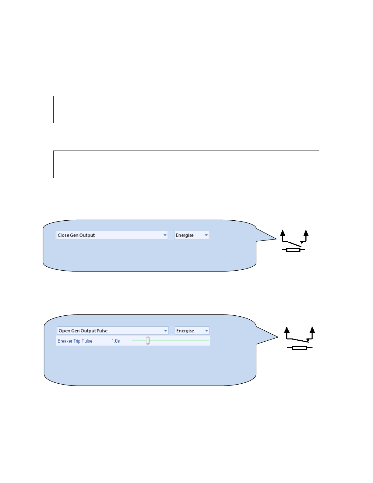
3.7.2.1 CONTACTOR COILS
Use output D, the normally open relay:
3.7.2.2 UNDERVOLTAGE (UV COILS)
Use output C, the normally closed relay :
Generator
DSE output drives the contactor coil, via external slave relay if required.
When the DSE module requires the contactor closed, the output energises (closing the internal
relay)
When the DSE module requires the contactor to be open, the output is de-energised (opening
the internal relay)
Generator
DSE output drives the UV coil, via external slave relay if required.
When the generator starts, the UV is powered via the normally closed relay. The breaker is now
ready for the close signal to be given. When the breaker is to be opened, the Open Gen erator
Pulse relay is operated, removing power from the UV coil for one second. This
causes the
breaker to trip (open) as the UV is no longer
powered. The Open Generator Pulse relay switches
back to its closed state, ready to power the UV coil the next time the generator starts.
Page 16
Specification
16
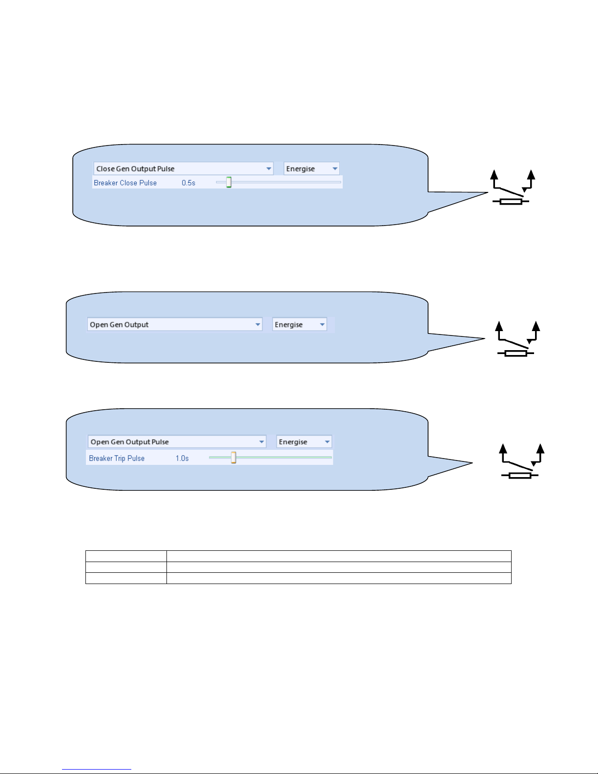
3.7.2.3 CLOSING COILS
For continuous closing signals (close signal is present continuously when the breaker is closed),
follow the instructions above as for Contactor Coils.
For momentary (pulsed) closing signals, use OUTPUT D, the normally open relay:
3.7.2.4 OPENING COILS / SHUNT TRIP COILS
For Continuous opening signal, use output D, the normally open relay:
For momentary (pulsed) closing signals, use a normally open relay:
3.7.3 OUTPUTS E,F,G,H, I & J
Number 6
Type Fully configurable, supplied from DC supply terminal 2.
Rating 3A resistiv e @ 35V
Generator:
When the DSE module requires the breaker open, the output energises (c los ing th e intern al r elay).
Generator:
When the DSE module requires the breaker open, the output energises (c los ing th e intern al r elay) for
the period of the breaker trip pulse.
Generator
When the DSE module requires the breaker closed, the output energises (closing the internal relay)
for the period of the Breaker Close Pulse timer after which the output is de-ener gis ed (opening the
internal relay).
Page 17
Specification
17
3.8 COMMUNICATION PORTS
USB Port USB2.0 Device for connection to PC running DSE configuration
suite only
Max distance 6m (yards)
Serial Communication RS232 and RS485 are both fitted but and provide independent
operation
RS232 Serial port
Non – Isolated port
Max Baud rate 115K baud subject to S/W
TX, RX, RTS, CTS, DSR, DTR, DCD
Male 9 way D type connector
Max distance 15m (50 feet)
RS485 Serial port
Isolated
Data connection 2 wire + common
Half Duplex
Data direction control for Transmit (by s/w protocol)
Max Baud Rate 19200
External termination required (120Ω)
Max common mode offset 70V (on board protection transorb)
Max distance 1.2km (¾ mile)
CAN Port Engine CAN Port
Standard implementation of ‘Slow mode’, up to 250K bits/s
Non-Isolated.
Internal Termination provided (120Ω )
Max distance 40m (133 feet)
NOTE:- For additional length, the DSE124 CAN Extender
is available. Please refer to DSE Publication: 057-116
DSE124 Operator Manual for more information.
Ethernet Auto detecting 10/100 Ethernet port.
3.9 COMMUNICATION PORT USAGE
3.9.1 CAN INTERFACE
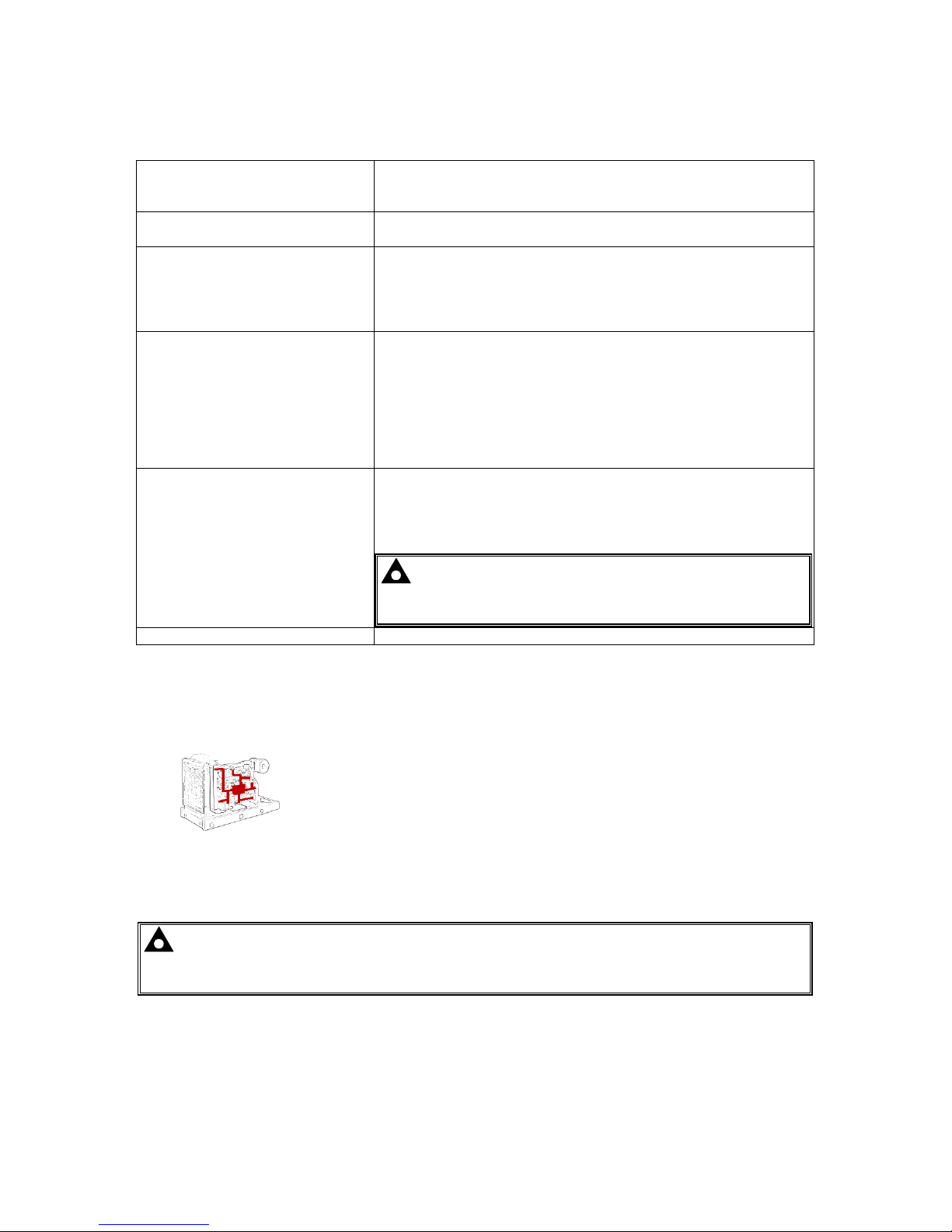
Modules are fitted with the CAN interface as standard and are capable of
receiving engine data from engine CAN controllers compliant with the
CAN standard.
CAN enabled engine controllers monitor the engine’s operating
parameters such as engine speed, oil pressure, engine temperature
(among others) in order to closely monitor and control the engine. The industry standard
communications interface (CAN) transports data gathered by the engine controller interface. This
allows generator controllers to access these engine parameters with no physical connection to the
sensor dev ice.
NOTE:- For further details for connections to CAN enabled engines and the functions
available with each engine type, refer to the manual Electronic Engines and DSE Wiring.
Part No. 057-004
Page 18
Specification
18
3.9.2 USB CONNECTION
The USB port is provided to give a simple means of connection between a PC and the controller.
Using the DSE Configuration Suite Software, the operator is then able to control the module, starting
or stopping the generator, selecting operating modes, etc.
Additionally, the various operating parameters (such as output volts, oil pressure, etc.) of the remote
generator are available to be viewed or changed.
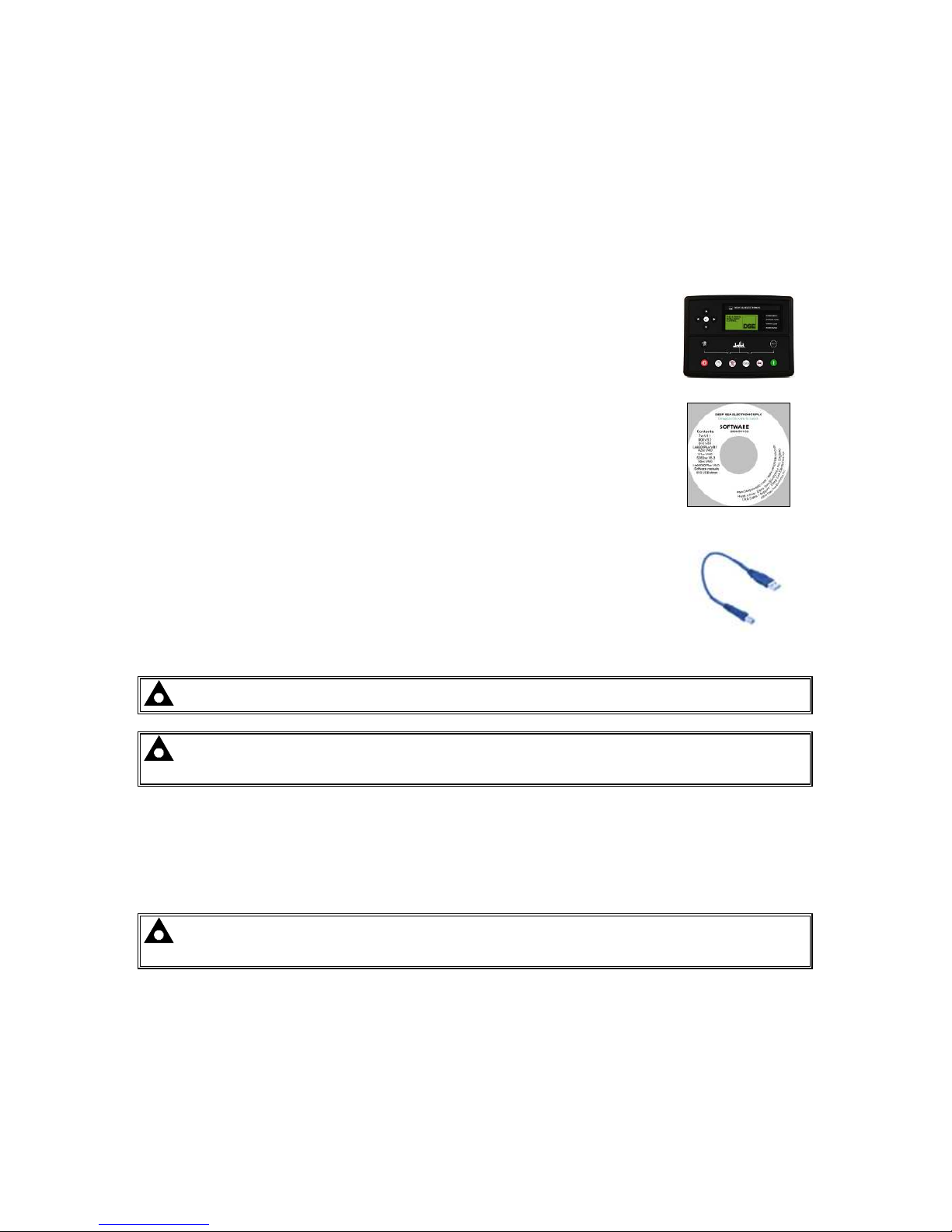
To connect a module to a PC by USB, the following items are required:
• DSE7400 series module
• DSE Configuration Suite PC Software
(Supplied on configuration suite software CD or available from
www.deepseaplc.com).
• USB cable Type A to Type B.
(This is the same cable as often used between a PC and a USB
printer)
DSE can supply this cable if required :
PC Configuration interface lead (USB type A – type B) DSE Part No
016-125
NOTE:- The DC supply must be connected to the module for configuration by PC.
NOTE:- Refer to DSE7400 Series Configuration Suite Manual (DSE part 057-160) for further
details on configuring, monitoring and control.
3.9.3 USB HOST-MASTER (USB DRIVE CONNECTION)
USB Type A connection for USB Host facility for USB storage device for data recording.
Maximum size of externally storage device is 16Gb.(see viewing the instrument pages)
NOTE:- Refer to DSE7400 Series Configuration Suite Manual (DSE part 057-160) for further
details on configuring, monitoring and control.
Page 19
Specification
19
3.9.4 RS232
The RS232 port on the controller supports the Modbus RTU protocol.
The Gencomm register table for the controller is available upon request from the DSE Technical
Support Department.
RS232 is for short distance communication (max 15m) and is typically used to connect the controller
to a telephone or GSM modem for more remote communications.
Many PCs are not fitted with an internal RS232 serial port. DSE DOES NOT recommend the use of
USB to RS232 convertors but can recommend PC add-ons to provide the computer with an RS232
port.
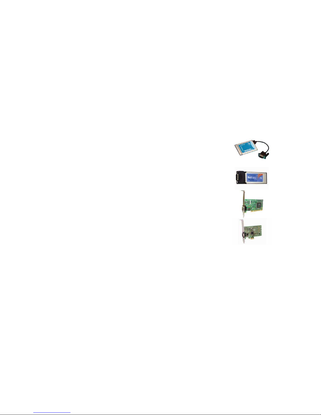
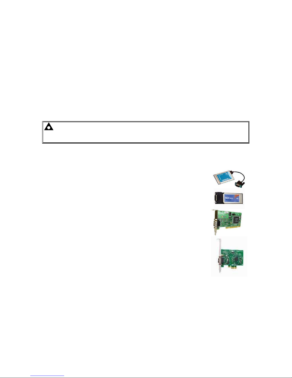
3.9.4.1 RECOMMENDED PC RS232 SERIAL PORT ADD-ONS
Remember to check these parts are suitable for your PC. Consult your PC supplier for further advice.
• Brainboxes PM143 PCMCIA RS232 card (for laptop PCs)
• Brainboxes VX-001 Express Card RS232 (for laptops and nettops PCs)
• Brainboxes UC246 PCI RS232 card (for desktop PCs)
• Brainboxes PX-246 PCI Express 1 Port RS232 1 x 9 Pin (for desktop
PCs)
Supplier:
NB DSE Have no business tie to Brainboxes. Over many years, our own engineers have used these
products and are happy to recommend them.
Page 20
Specification
20
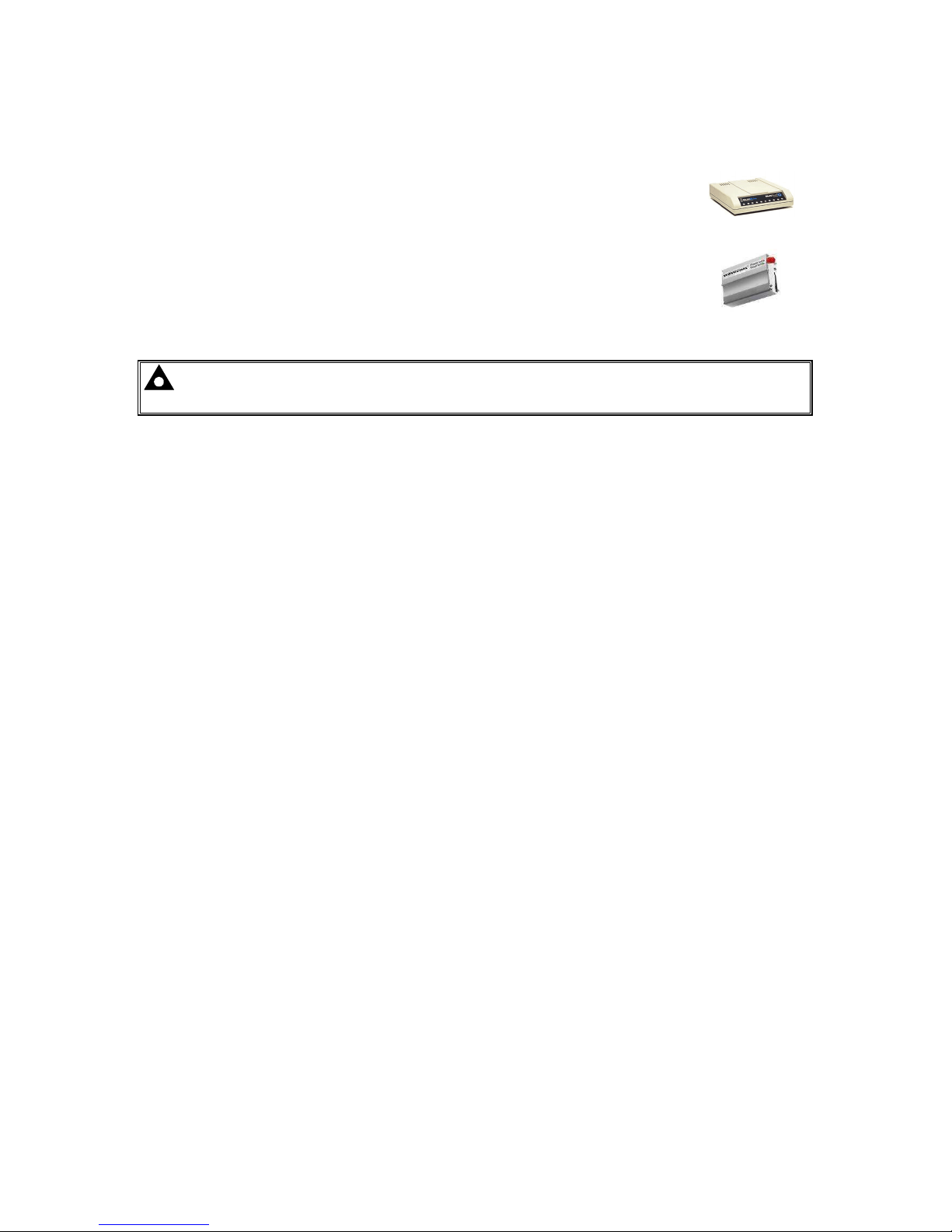
3.9.4.2 RECOMMENDED EXTERNAL MODEMS:
• Multitech Global Modem – MultiModem ZBA (PSTN)
DSE Part Number 020-252
(Contact DSE Sales for details of localisation kits for these modems)
• Sierra Fastrak Xtend GSM modem kit (PSU, Antenna and modem)*
DSE Part number 0830-001-01
NOTE: *For GSM modems a SIM card is required, supplied by your GSM network provider
:
• For SMS only, a ‘normal’ voice SIM card is required. This enables the controller to send SMS
messages to designated mobile phones upon status and alarm conditions.
• For a data connection to a PC running DSE Configuration Suite Software, a ‘special’ CSD
(Circuit Switched Data) SIM card is required that will enable the modem to answer an
incoming data call. Many ‘pay as you go’ services will not provide a CSD (Circuit Switched
Data) SIM card.
Page 21
Specification
21
3.9.5 RS485
The RS485 port on the series controller supports the Modbus RTU protocol.
The DSE Gencomm register table for the controller is av ailable upon request from the DSE Technical
Support Department.
RS485 is used for point-to-point cable connection of more than one device (maximum 32 devices)
and allows for connection to PCs, PLCs and Building Management Systems (to name just a few
devices).
One advantage of the RS485 interface is the large distance specification (1.2km when using Belden
9841 (or equivalent) cable. This allows for a large distance between the module and a PC running the
DSE Configuration Suite software. The operator is then able to control the module, starting or
stopping the generator, selecting operating modes, etc.
The various operating parameters (such as output volts, oil pressure, etc.) of the remote generator
can be viewed or changed.
NOTE:- For a single module to PC connection and distances up to 6m (8yds) the USB
connection method is more suitable and provides for a lower cost alternative to RS485 (which
is more suited to longer distance connections).
3.9.5.1 RECOMMENDED PC RS485 SERIAL PORT ADD-ONS
Remember to check these parts are suitable for your PC. Consult your PC supplier for further advice.
• Brainboxes PM154 PCMCIA RS485 card (for laptops PCs)
Set to ‘Half Duplex, Autogating” with ‘CTS True’ set to ‘enabled’
• Brainboxes VX-023 ExpressCard 1 Port RS422/485 (for laptops and
nettop PCs)
• Brainboxes UC320 PCI Velocity RS485 card (for desktop PCs)
Set to ‘Half Duplex, Autogating” with ‘CTS True’ set to ‘enabled’
• Brainboxes PX-324 PCI Express 1 Port RS422/485 (for desktop PCs)
Supplier:
NB DSE have no business tie to Brainboxes. Over many years,our own engineers have used these
products and are happy to recommend them.
Page 22
Specification
22
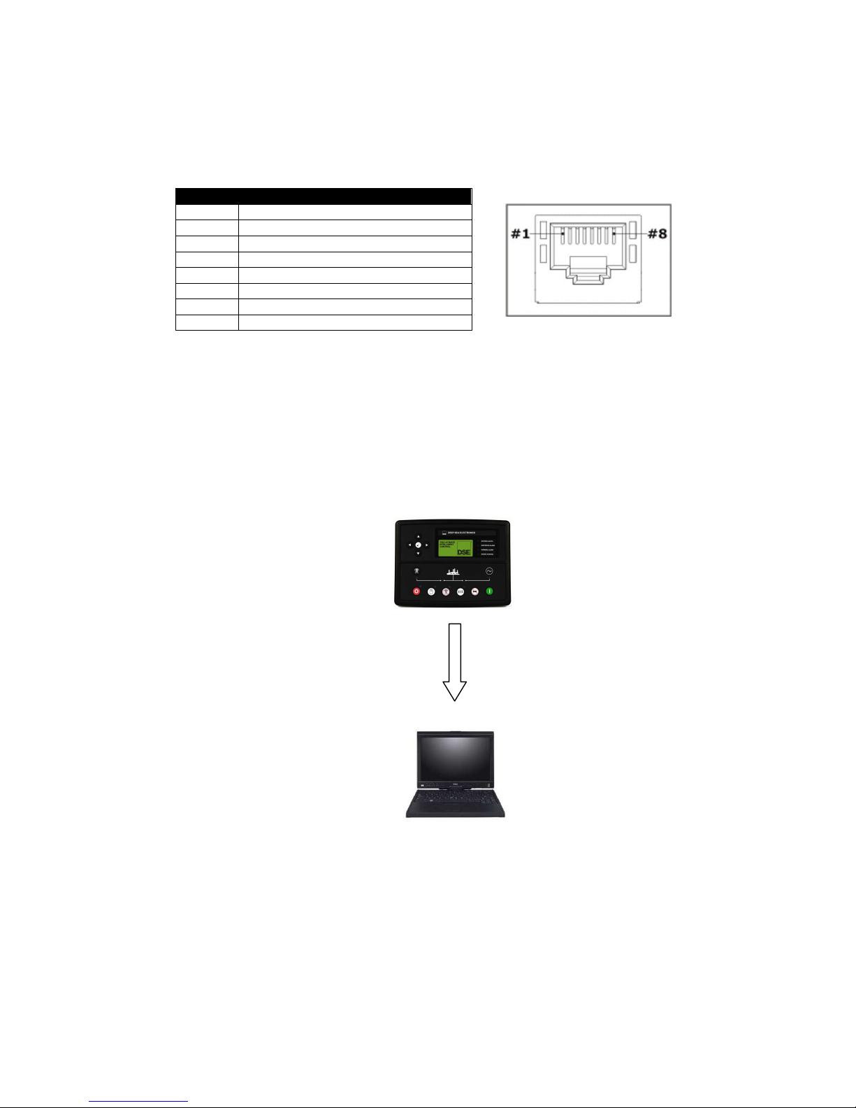
3.9.6 ETHERNET
The module is fitted with ETHERNET socket for connection to LAN (local area networks)
Description
1
TX+
2
TX-
3
RX+
4
Do not connect
5
Do not connect
6
RX-
7
Do not connect
8
Do not connect
3.9.6.1 DIRECT PC CONNECTION
Requirements
• DSE7400 series module
• Crossover Ethernet cable (see Below)
• PC with Ethernet port
Crossover
network cable
Page 23
Specification
23
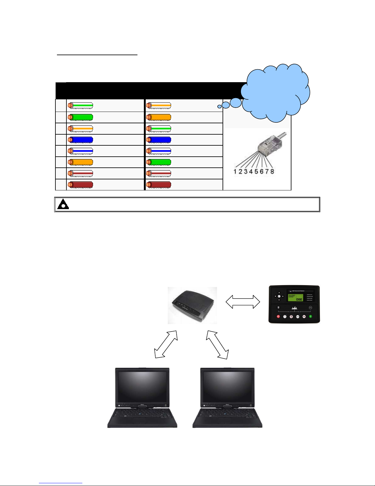
Crossover cable wiring detail
Two pairs crossed, two pairs uncrossed
10baseT/100baseTX crossover
Pi
n
Connection 1 (T568A)
Connection 2 (T568B)
1
white/green stripe
white/orange stripe
2
green solid
orange solid
3
white/orange stripe
white/green stripe
4
blue solid
blue solid
5
white/blue stripe
white/blue stripe
6
orange solid
green solid
7
white/brown stripe
white/brown stripe
8
brown solid
brown solid
NOTE:- This cable can be purchased from any good PC or IT store.
3.9.6.2 CONNECTION TO BASIC ETHERNET
Requirements
• DSE7400 series module
• Ethernet cable (see below)
• Working Ethernet (company or home network)
• PC with Ethernet port
For the advanced
Engineer, a cross over
cable is a CAT5 cable
with one end
terminated as T 568A
and the other end
terminated as T 568B.
Ethernet router
or ADSL router
Ethernet cable
Page 24
Specification
24
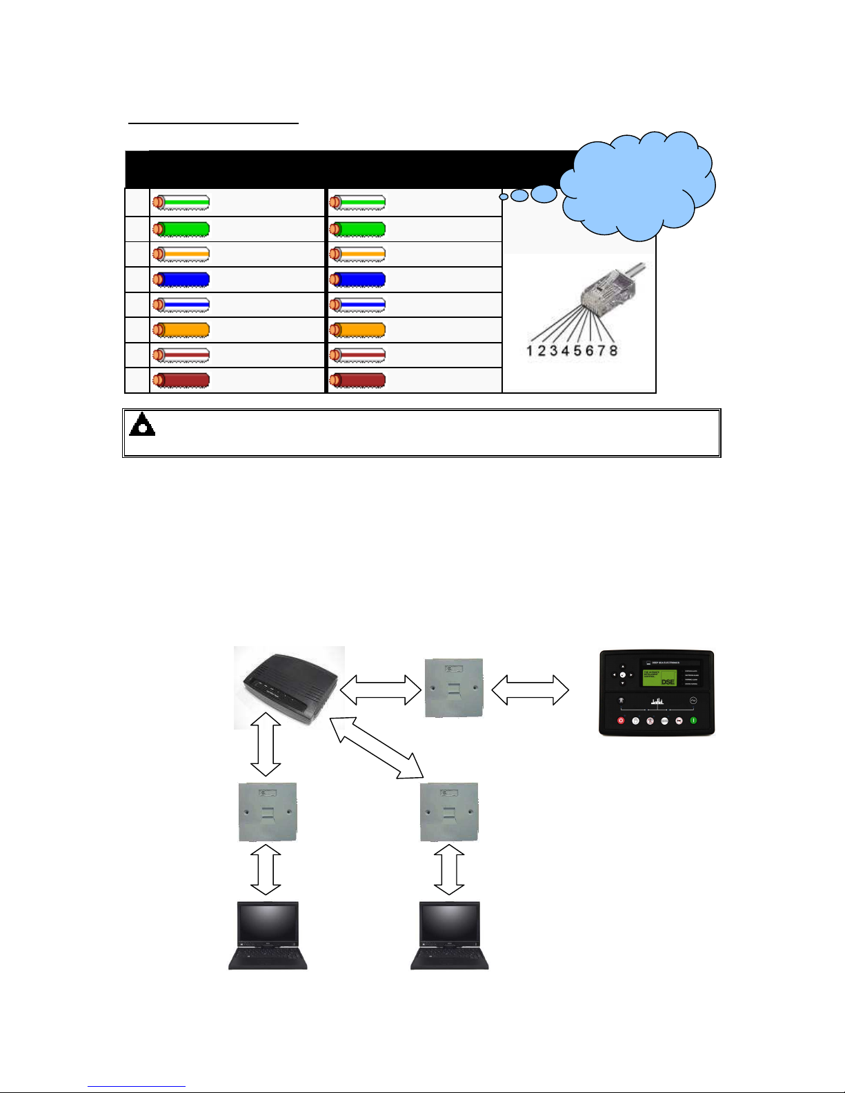
Ethernet cable wiring detail
.
10baseT/100baseT
Pi
n
Connection 1 (T568A)
Connection 2 (T568A)
1
white/green stripe
white/green stripe
2
green solid
green solid
3
white/orange stripe
white/orange stripe
4
blue solid
blue solid
5
white/blue stripe
white/blue stripe
6
orange solid
orange solid
7
white/brown stripe
white/brown stripe
8
brown solid
brown solid
NOTE:- DSE Stock a 2m (2yds) Ethernet Cable – Part number 016-137. Alternatively they
can be purchased from any good PC or IT store.
3.9.6.3 CONNECTION TO COMPANY INFRASTRUCTURE ETHERNET
Requirements
• DSE7400 series module
• Ethernet cable (see below)
• Working Ethernet (company or home network)
• PC with Ethernet port
For the advanced
Engineer, this cable
has both ends
terminated as T 568A
(as shown below) or
T568B.
Ethernet cable
PC Network
wall connection
sockets
Ethernet router
or ADSL router
Page 25
Specification
25
Ethernet cable wiring detail
10baseT/100baseT
Pi
n
Connection 1 (T568A)
Connection 2 (T568A)
1
white/green stripe
white/green stripe
2
green solid
green solid
3
white/orange stripe
white/orange stripe
4
blue solid
blue solid
5
white/blue stripe
white/blue stripe
6
orange solid
orange solid
7
white/brown stripe
white/brown stripe
8
brown solid
brown solid
NOTE:- DSE Stock a 2m (2yds) Ethernet Cable – Part number 016-137. Alternatively they
can be purchased from any good PC or IT store.
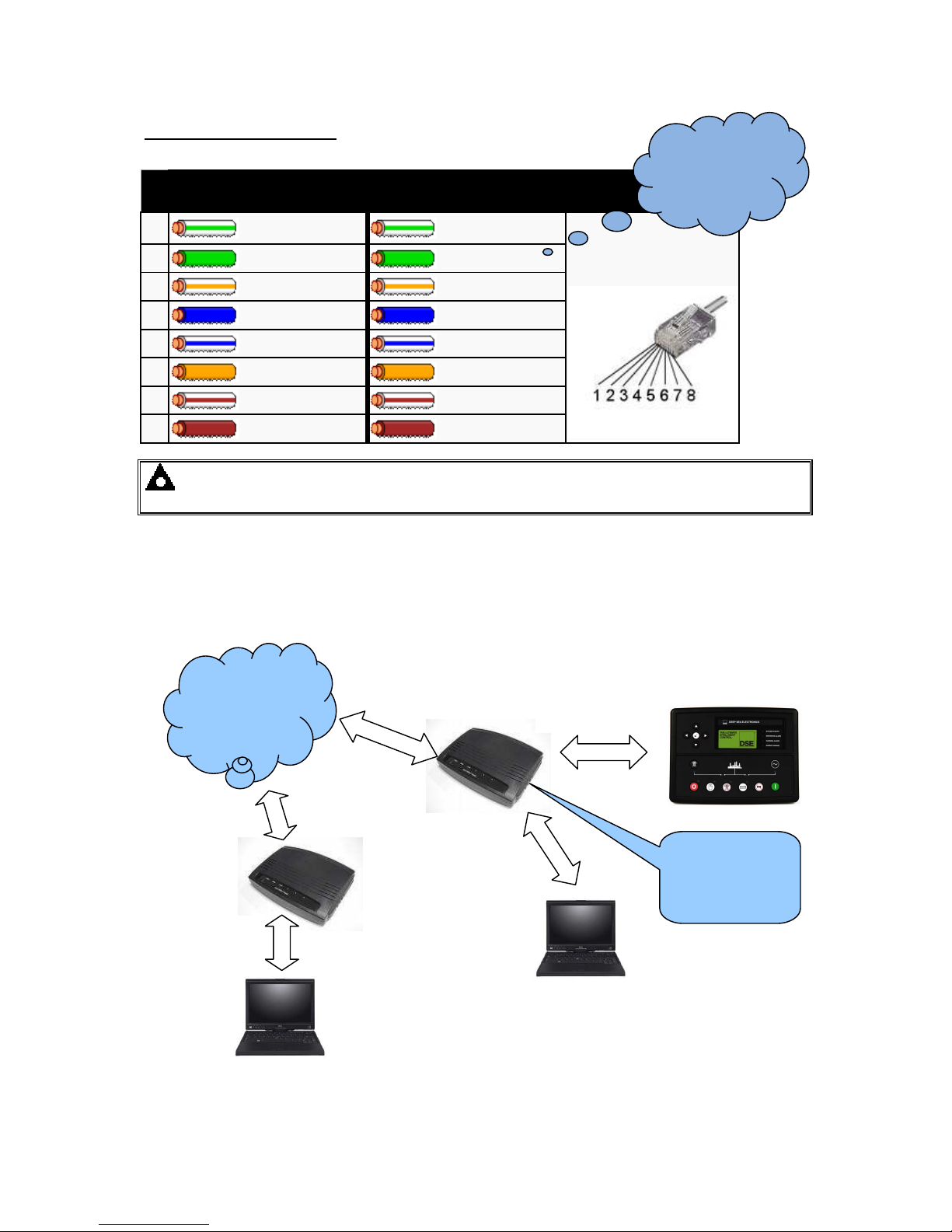
3.9.6.4 CONNECTION TO THE INTERNET
Requirements
• Ethernet cable (see below)
• Working Ethernet (company or home network)
• Working Internet connection (ADSL or DSL recommended)
For the advanced
Engineer, this cable
has both ends
terminated as T 568A
(as shown below) or
T568B.
DSL or ADSL
router
Optional ‘Local’
site PC
INTERNET
DSL or ADSL
router
PC remote
from generator
The DSL/ADSL
router will route
external network
traffic.
Ethernet cable
Page 26
Specification
26
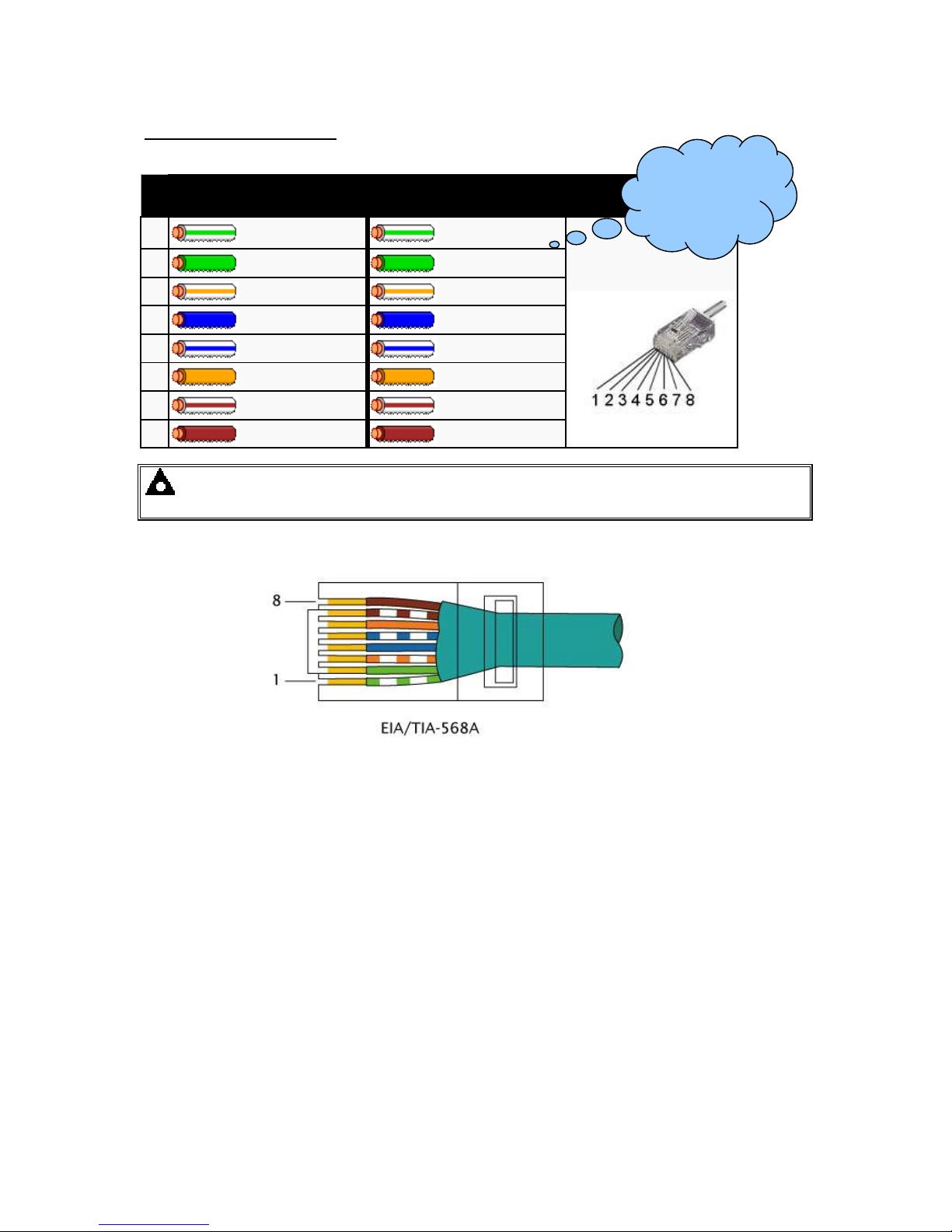
Ethernet cable wiring detail
10baseT/100baseT
Pi
n
Connection 1 (T568A)
Connection 2 (T568A)
1
white/green stripe
white/green stripe
2
green solid
green solid
3
white/orange stripe
white/orange stripe
4
blue solid
blue solid
5
white/blue stripe
white/blue stripe
6
orange solid
orange solid
7
white/brown stripe
white/brown stripe
8
brown solid
brown solid
NOTE:- DSE Stock a 2m (2yds) Ethernet Cable – Part number 016-137. Alternatively they
can be purchased from any good PC or IT store.
For the advanced
Engineer, this cable
has both ends
terminated as T 568A
(as shown below) or
T568B.
Page 27

Specification
27
3.9.6.5 FIREWALL CONFIGURATION FOR INTERNET ACCESS
As modem/routers differ enormously in their configuration, it is not possible for DSE to give a
complete guide to their use with the module. However it is possible to give a description of the
requirements in generic terms. For details of how to achieve the connection to your modem/router
you are referred to the supplier of your modem/router equipment.
The module makes its data available over Modbus TCP and as such communicates over the
Ethernet using a Port configured via the DSE Configuration Suite software..
You must configure your modem/router to allow inbound traffic on this port. For more information you
are referred to your WAN interface device (modem/router) manufacturer.
It is also important to note that if the port assigned (setting from software “Modbus Port Number”) is
already in use on the LAN, the module cannot be used and another port must be used .
Outgoing Firewall rule
As the module makes its user interface available to standard web browsers, all communication uses
the chosen port. It is usual for a firewall to make the same port outgoing open for communication.
Incoming traffic (virtual server)
Network Address and Port Translation (NAPT) allows a single device, such as the modem/router
gateway, to act as an agent between the Internet (or "public external network") and a local (or
"internal private") network. This means that only a single, unique IP address is required to represent
an entire group of computers.
For our application, this means that the WAN IP address of the modem/router is the IP address we
need to access the site from an external (internet) location.
When the requests reach the modem/router, we want this passed to a ‘virtual serv er’ for handling, in
our case this is the module.
Result : Traffic arriving from the WAN (internet) on port xxx is automatically sent to IP address set
within the configuration software on the LAN for handling.
NOTE:- Refer to DSE7400 Series Configuration Suite Manual (DSE part 057-160) for further
details on configuring, monitoring and control.
Page 28
Specification
28
3.10 DSENET® FOR EXPANSION MODULES
DSENet® is the interconnection cable between the host controller and the expansion module(s) and
must not be connect to any device other than DSE equipment designed for connection to the
DSENet®
Cable type Two core screened twisted pair
Cable characteristic
impedance
120Ω
Recommended cable Belden 9841
Belden 9271
Maximum cable length 1200m (¾ mile) when using Belden 9841 or direct equivalent.
600m (666 yds) when using Belden 9271 or direct equivalent.
DSENet® topology “Daisy Chain” Bus with no stubs (spurs)
DSENet® termination
120Ω. Fitted internally to host controller. Must be fitted externally to
the ‘last’ expansion module by the customer.
Maximum expansion
modules
Total 20 devices made up of DSE2130 (up to 4), DSE2131 (up to 4),
DSE2133 (up to 4), DSE2152 (up to 4), DSE2157 (up to 10), DSE2548
(up to 10)
This gives the possibility of :
Maximum 32 additional 0-10V or 4-20mA outputs (DSE2152)
Maximum 80 additional relay outputs (DSE2157)
Maximum 80 additional LED indicators
Maximum 24 additional Ratio-metric or Thermocouple inputs
(DSE2133).
Maximum 40 additional inputs (All can be configured as either digital,
resistive, 0-10V or 4-20mA when using DSE2131)
NOTE: As a termination resistor is internally fitted to the host controller, the host
controller must be the ‘first’ unit on the DSENet®. A termination resistor MUST be fitted to the
‘last’ unit on the DSENet®. For connection details, you are referred to the section entitled
‘typical wiring diagram’ elsewhere in this document.
NOTE : DSE7400 series module does not support the DSE2510/2520 display modules.
3.10.1 DSENET® USED FOR MODBUS ENGINE CONNECTION
As DSENet® utilises an RS485 hardware interface, this port can be configured for connection to
Cummins Modbus engines (Engines fitted with Cummins GCS).
This leaves the RS485 interface free for connection to remote monitoring equipment (i.e. Building
Management System, PLC or PC RS485 port).
While this is a very useful feature in some applications, the obvious drawback is that the DSENet®
interface is no longer available for connection to expansion devices.
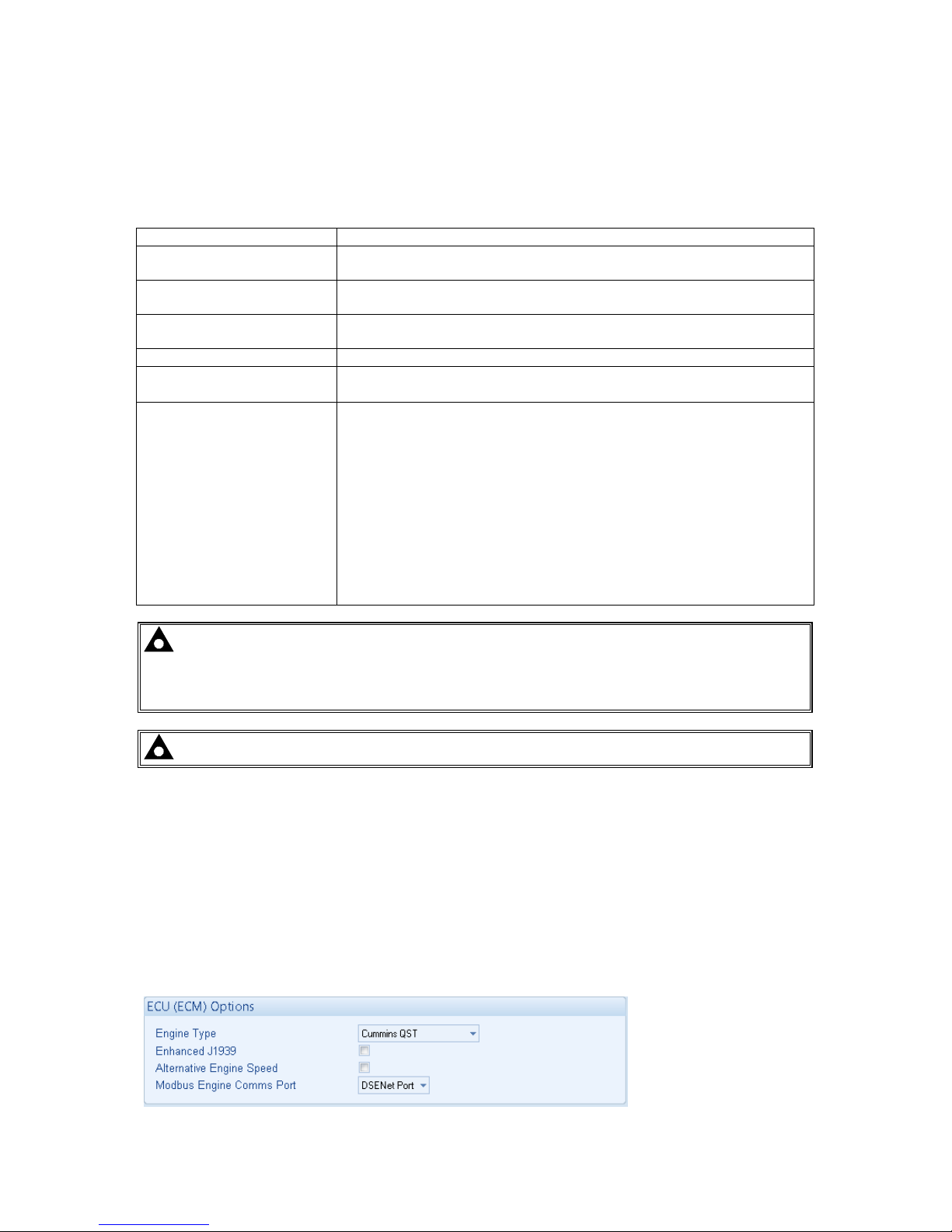
Example of configuring the DSENet® for connection to Cummins QST GCS using the DSE
Configuration Suite Software:
Page 29
Specification
29
3.11 SOUNDER
The module features an internal sounder to draw attention to warning, shutdown and electrical trip
alarms.
Sounder level 64db @ 1m
3.11.1 ADDING AN EXTERNAL SOUNDER TO THE APPLICATION
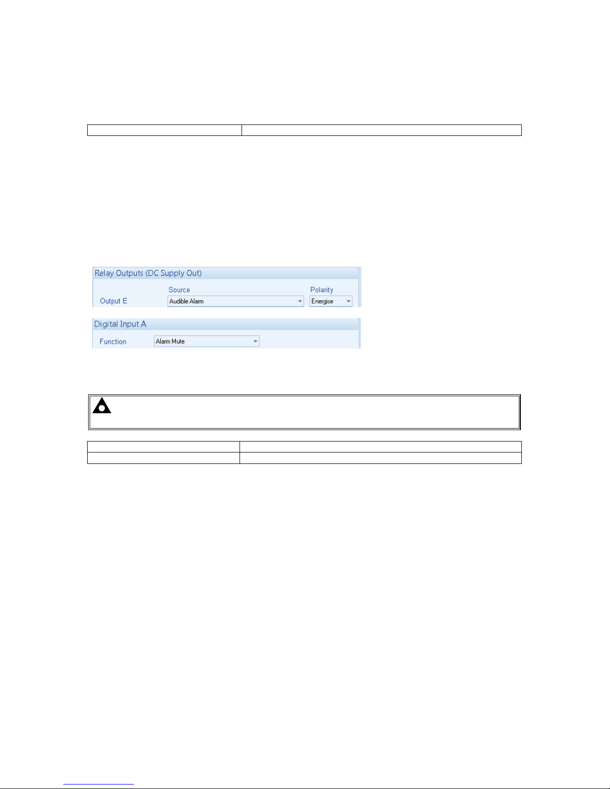
Should an external alarm or indicator be required, this can be achieved by using the DSE
Configuration Suite PC software to configure an auxiliary output for “Audible Alarm”, and by
configuring an auxiliary input for “Alarm Mute” (if required).
The audible alarm output activates and de-activates at the same time as the module’s internal
sounder. The Alarm mute input and internal alarm mute button activate ‘in parallel’ with each other.
Either signal will mute both the internal sounder and audible alarm output.
Example of configuration to achieve external sounder with external alarm mute button:
3.12 ACCUMULATED INSTRUMENTATION
NOTE: When an accumulated instrumentation value exceeds the maximum number as
listed below, it will reset and begin counting from zero again.
Engine hours run Maximum 99999 hrs 59 minutes (approximately 11yrs 4months)
Number of starts 1,000,000 (1 million)
The number of logged Engine Hours and Number of Starts can be set/reset using the DSE
Configuration Suite PC software. Depending upon module configuration, this may have been PIN
number locked by your generator supplier
Page 30
Specification
30
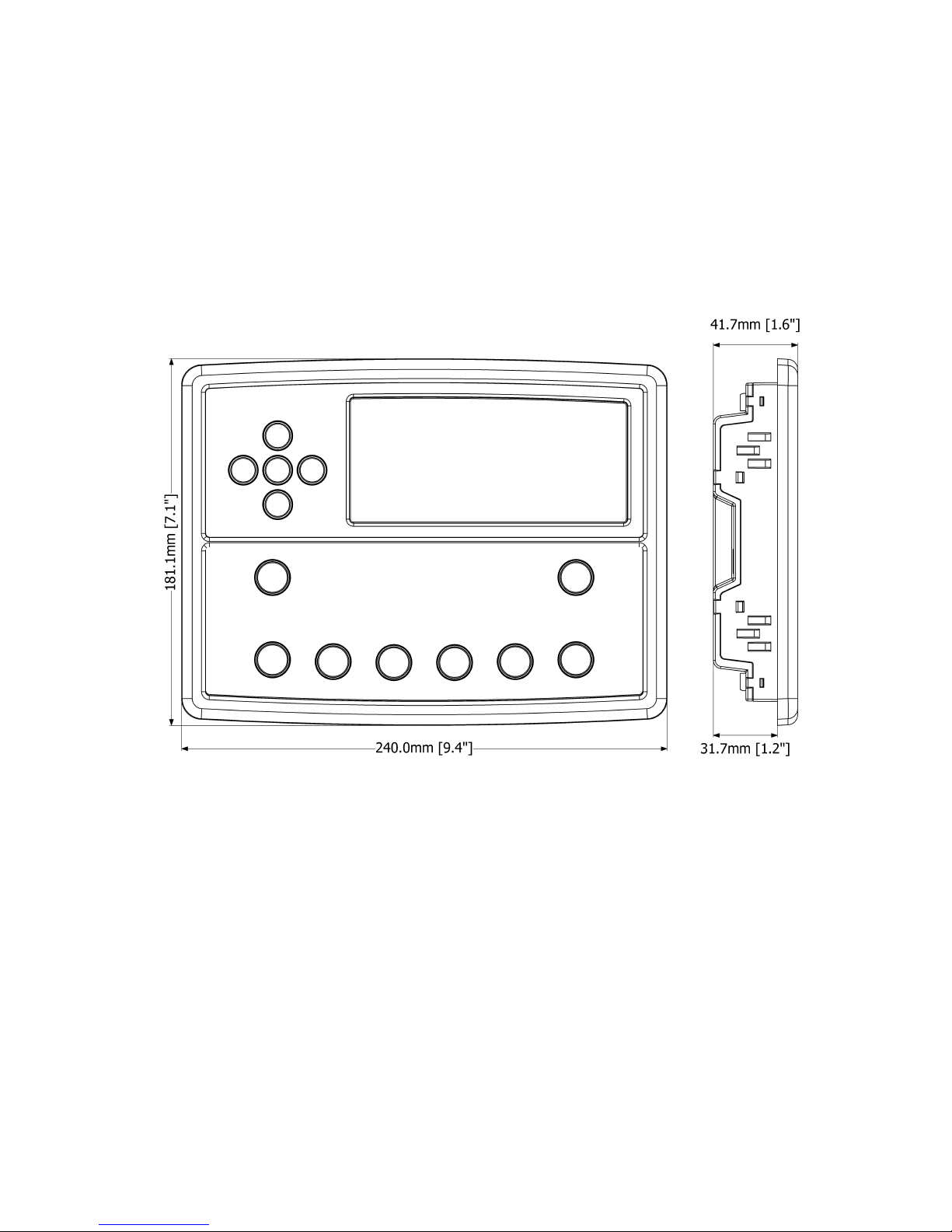
3.13 DIMENSIONS AND MOUNTING
3.13.1 DIMENSIONS
240.0mm x 181.1mm x 41.7mm
(9.4” x 7.1” x 1.6”)
3.13.2 PANEL CUTOUT
220mm x 160mm
(8.7” x 6.3”)
3.13.3 WEIGHT
0.7kg (1.4lb)
Page 31
Specification
31
3.13.4 FIXING CLIPS
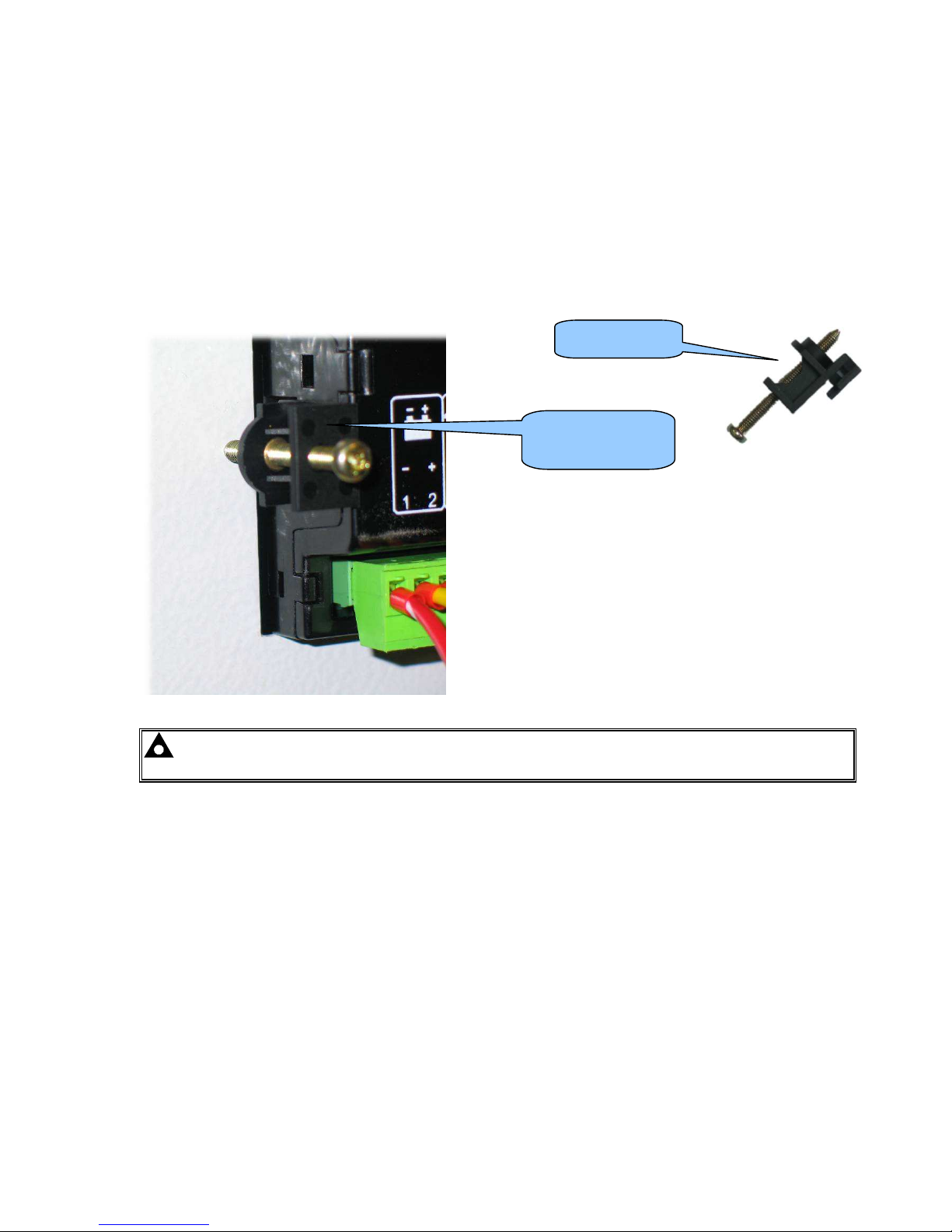
The module is held into the panel fascia using the supplied fixing clips.
• Withdraw the fixing clip screw (turn anticlockwise) until only the pointed end is protruding
from the clip.
• Insert the three ‘prongs’ of the fixing clip into the slots in the side of the module case.
• Pull the fixing clip backwards (towards the back of the module) ensuring all three prongs of
the clip are inside their allotted slots.
• Turn the fixing clip screws clockwise until they make contact with the panel fascia.
• Turn the screws a little more to secure the module into the panel fascia. Care should be taken
not to ov er tighten the fixing clip screws.
NOTE:- In conditions of excessive vibration, mount the module on suitable anti-vibration
mountings.
Fixing clip fitted to
module
Fixing clip
Page 32
Specification
32
3.13.5 CABLE TIE FIXING POINTS
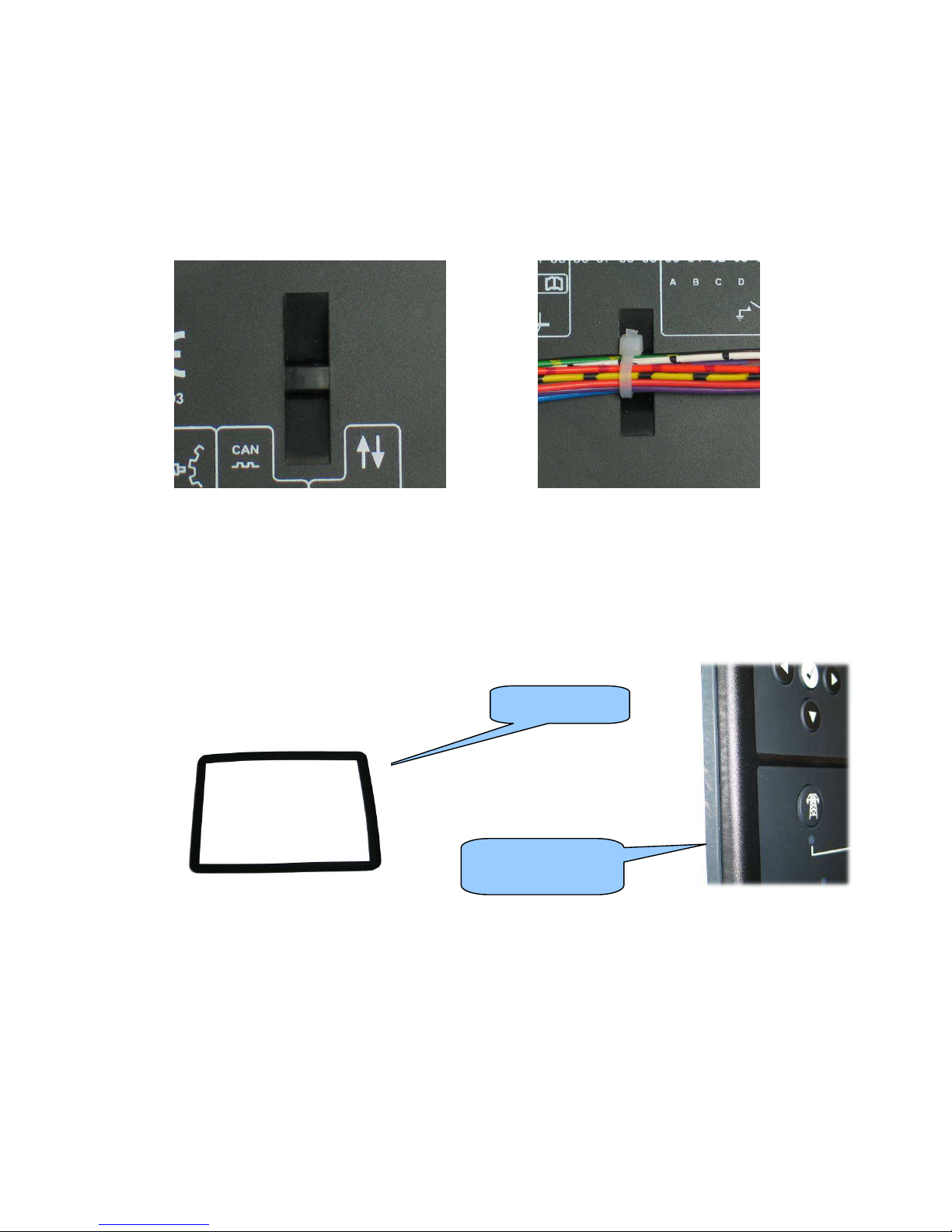
Integral cable tie fixing points are included on the rear of the module’s case to aid wiring. This
additionally prov ides strain relief to the cable loom by removing the weight of the loom from the
screw connectors, thus reducing the chance of future connection failures.
Care should be taken not to over tighten the cable tie (for instance with cable tie tools) to prevent the
risk of damage to the module case.
Cable tie fixing point With cable and tie in place
3.13.6 SILICON SEALING GASKET
The supplied silicon gasket provides improved sealing between module and the panel fascia.
The gasket is fitted to the module before installation into the panel fascia.
Take care to ensure the gasket is correctly fitted to the module to maintain the integrity of the seal.
Gasket fitted to
module
Sealing gasket
Page 33

Specification
33
3.14 APPLICABLE STANDARDS
BS 4884-1
This document conforms to BS4884-1 1992 Specification for presentation
of essential information.
BS 4884-2 This document conforms to BS4884-2 1993 Guide to content
BS 4884-3 This document conforms to BS4884-3 1993 Guide to presentation
BS EN 60068-2-1
(Minimum
temperature)
-30°C (-22°F)
BS EN 60068-2-2
(Maximum
temperature)
+70°C (158°F)
BS EN 60950
Safety of information technology equipment, including electrical business
equipment
BS EN 61000-6-2
EMC Generic Immunity Standard (Industrial)
BS EN 61000-6-4
EMC Generic Emission Standard (Industrial)
BS EN 60529
(Degrees of protection
provided by enclosures)
IP65 (front of module when installed into the control panel with the
supplied sealing gasket)
IP42 (front of module when installed into the control panel WITHOUT
being sealed to the panel)
UL508
NEMA rating
(Approximate)
12 (Front of module when installed into the control panel with the supplied
sealing gasket).
2 (Front of module when installed into the control panel WITHOUT being
sealed to the panel)
IEEE C37.2
(Standard Electrical
Power System Device
Function Numbers and
Contact Designations)
Under the scope of IEEE 37.2, function numbers can also be used to
represent functions in microprocessor devices and software programs.
The controller is device number 11L-8000 (Multifunction device protecting
Line (generator) –module).
As the module is configurable by the generator OEM, the functions
covered by the module will vary. Under the module’s factory configuration,
the device numbers included within the module are :
2 – Time delay starting or closing relay
3 – Checking or interlocking relay
5 – Stopping Device
6 – Starting circuit breaker
8 – Control power disconnecting device
10 – Unit sequence switch
11 – Multifunction device
12 – Overspeed device
14 – Underspeed device
23 – Temperature control device
26 – Apparatus thermal device
27AC – AC undervoltage relay
27DC – DC undervoltage relay
29 – Isolating contactor or switch
30 – Annunciator relay
31 – Separate Excitation Dev ice
37 – Undercurrent or underpower relay (USING INTERNAL PLC EDITOR)
41 – Field circuit breaker
42 – Running circuit breaker
44 – Unit sequence relay
46 – Reverse-phase or phase-balance current relay
48 – Incomplete sequence relay
49 – Machine or transformer thermal relay
Continued overleaf.
Page 34

Specification
34
IEEE C37.2
(Standard Electrical
Power System Device
Function Numbers and
Contact Designations)
Continued
50 – Instantaneous ov ercurrent relay
51 – AC time ov ercurrent relay
52 – AC circuit breaker
53 – Exciter or DC generator relay
54 – Turning gear engaging device
55 – Power factor relay (USING INTERNAL PLC EDITOR)
59AC – AC ov ervoltage relay
59DC – DC overvoltage relay
62 – Time delay stopping or opening relay
63 – Pressure switch
71 – Level switch
74 – Alarm relay
78 – Phase-angle measuring relay
79 – Reclosing relay (USING INTERNAL PLC EDITOR)
81 – Frequency relay
83 – Automatic selective control or transfer relay
86 – Lockout relay
In line with our policy of continual development, Deep Sea Electr onic s, reserve the right to change s pec if ication without notice.
Page 35
Specification
35
3.14.1 ENCLOSURE CLASSIFICATIONS
IP CLASSIFICATIONS
The modules specification under BS EN 60529 Degrees of protection provided by enclosures
IP65 (Front of module when module is installed into the control panel with the optional sealing gasket).
IP42 (front of module when module is installed into the control panel WITHOUT being sealed to the panel)
First Digit Second Digit
Protection against contact and ingress of solid objects Protection against ingress of water
0 No protection 0 No protection
1 Protected against ingress solid objects with a diameter of
more than 50 mm. No protection against deliberate
access , e.g. with a hand, but large su rf aces of the body
are prevented f rom approach.
1 Protection against dripping water falling vertically. N o harmf ul
eff ect must be produced (vertically falling d rops ).
2 Protected against penetration by solid objects with a
diameter of more than 12 mm. Fingers or similar objects
prevented f rom approach.
2 Protection against dripping water falling vertically. T her e must
be no harmful effect when the equipment (enclosure) is tilted
at an angle up to 15° f rom its normal pos iti on ( drops falling at
an angle).
3 Protected against ingress of solid objects with a diameter
of more than 2.5 mm. T ools, wi res etc . with a thic kness of
more than 2.5 mm are prevented from approach.
3 Protection against water falling at any angle up to 60° from
the vertical. There must be no harmful effect (spray water).
4 Protected against ingress of solid objects with a diameter
of more than 1 mm. Tools, wir es etc. with a thickness of
more than 1 mm are prevented from approach.
4 Protection against water splashed against the equipment
(enclosure) from any direction. There must be no harmful
eff ect (splashing water).
5 Protected against harmful dust deposits. Ingress of dust
is not totally prevented but the dust must not enter in
sufficient quantity to interface with satisfactory operation
of the equipment. C omplete protec tion agains t c ontact.
5 Protection against water projected from a nozzle against the
equipment (enclosur e) from any dir ect ion. There mus t be no
harmful effect (water jet).
6 Protection against ingress of dust (dust tight). Complete
protection against contact.
6 Protection against heavy seas or powerful water jets. Water
must not enter the equipment (enclosure) in harmful
quantities (splashing over).
Page 36
Specification
36
3.14.2 NEMA CLASSIFICATIONS
The modules NEMA Rating (Approximate)
12 (Front of module when module is installed into the control panel with the optional sealing gasket).
2 (front of module when module is installed into the control panel WITHOUT being sealed to the panel)
NOTE: - There is no direct equivalence between IP / NEMA ratings. IP figures shown are
approximate only.
1
IP30
Provides a degree of protection against contact with the enclosure equipment and against a limited amount of falling dirt.
2
IP31
Provides a degree of protection against limited amounts of falling water and dirt.
3
IP64
Provides a degree of protection against windblown dust, rain and sleet; undamaged by the formation of ice on the
enclosure.
3R
IP32
Provides a degree of protection against rain and sleet:; undamaged by the for mation of ice on the enclos ure.
4 (X)
IP66
Provides a degree of protection against splashing water, windblown dus t and rain, hose directed water; undamaged by the
formation of ice on the enclosure. (Resist corrosion).
12/12K
IP65
Provides a degree of protection against dust, falling dirt and dripping non corrosive liquids.
13
IP65
Provides a degree of protection against dust and spraying of water, oil and non corrosive coolants.
Page 37
Installation – Terminal Description
37
4 INSTALLATION
The module is designed to be mounted on the panel fascia. For dimension and mounting details, see
the section entitled Specification, Dimension and mounting elsewhere in this document.
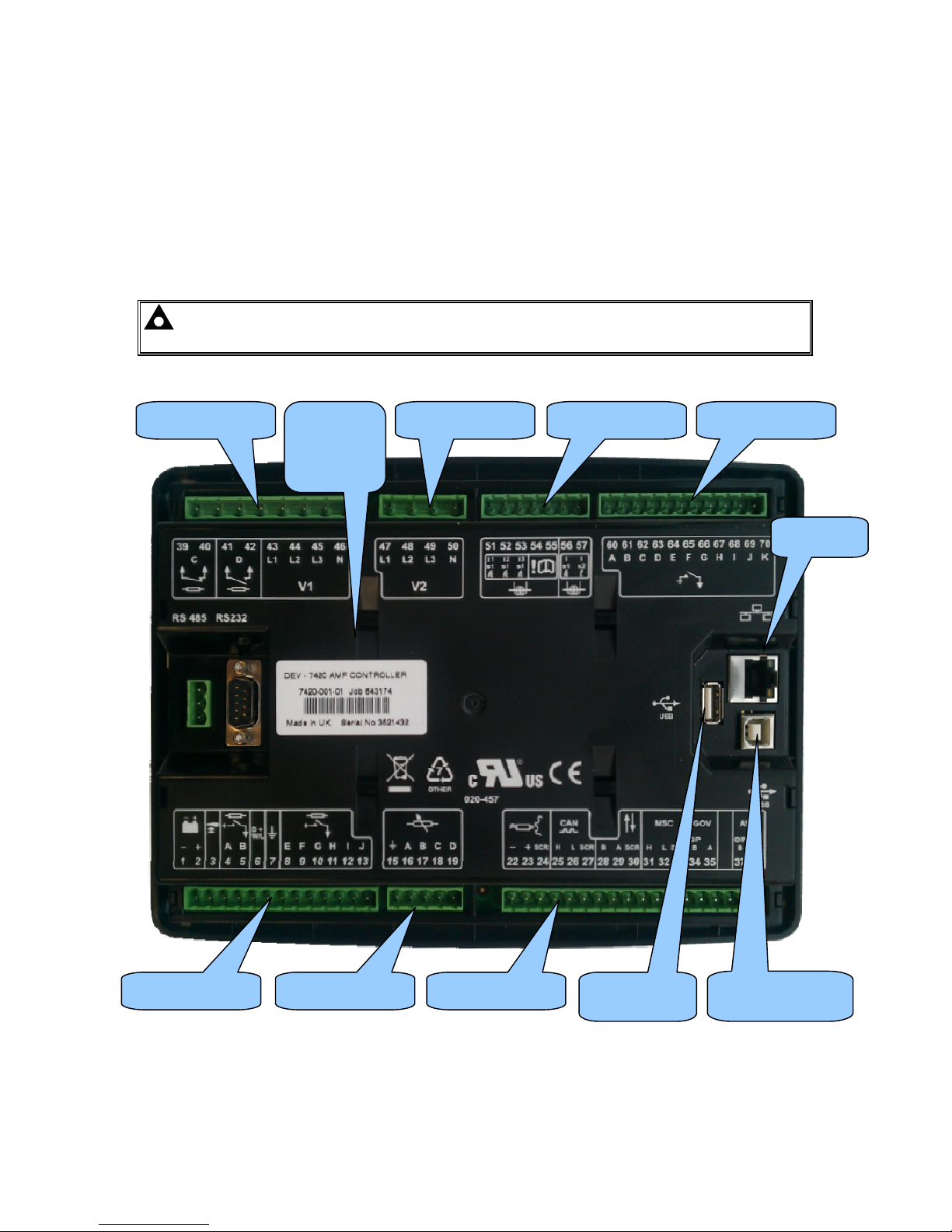
4.1 TERMINAL DESCRIPTION
To aid user connection, icons are used on the rear of the module to help identify terminal functions.
An example of this is shown below.
NOTE : Availability of some terminals depends upon module version. Full details are
given in the section entitled Terminal Description elsewhere in this manual.
Terminals 1-13 Terminals 15-19 Terminals 22-36
Terminals 39-46 Terminals 47-50 Terminals 51-57 Terminals 60-68
USB
PC Configuration
USB Host
Data Logging
Serial and
part
number
label
Ethernet
Page 38
Installation – Terminal Description
38
4.1.1 DC SUPPLY, FUEL AND START OUTPUTS, OUTPUTS E-J
PIN
No
DESCRIPTION CABLE
SIZE
NOTES
1
DC Plant Supply Input
(Negative)
2.5mm²
AWG 13
2
DC Plant Supply Input
(Positive)
2.5 mm²
AWG 13
(Recommended Maximum Fuse 15A anti-surge)
Supplies the module (2A anti-surge requirement) and
Output relays E,F,G & H
3 Emergency Stop Input
2.5mm²
AWG 13
Plant Supply Positive. Also supplies outputs 1 & 2.
(Recommended Maximum Fuse 20A)
4 Output relay A (FUEL)
2.5mm²
AWG 13
Plant Supply Positive from terminal 3. 15 Amp rated.
Fixed as FUEL relay if electronic engine is not configured.
5 Output relay B (START)
2.5mm²
AWG 13
Plant Supply Positive from terminal 3. 15 Amp rated.
Fixed as START relay if electronic engine is not
configured.
6 Charge fail / excite
2.5mm²
AWG 13
Do not connect to ground (battery negative).
If charge alternator is not fitted, leave this terminal
disconnected.
7 Functional Earth
2.5mm²
AWG 13
Connect to a good clean earth point.
8 Output relay E
1.0mm²
AWG 18
Plant Supply Positive from terminal 2. 2 Amp rated.
9 Output relay F
1.0mm²
AWG 18
Plant Supply Positive from terminal 2. 2 Amp rated.
10 Output relay G
1.0mm²
AWG 18
Plant Supply Positive.from terminal 2. 2 Amp rated.
11 Output relay H
1.0mm²
AWG 18
Plant Supply Positive from terminal 2. 2 Amp rated.
12 Output relay I
1.0mm²
AWG 18
Plant Supply Positive from terminal 2. 2 Amp rated.
13 Output relay J
1.0mm²
AWG 18
Plant Supply Positive from terminal 2. 2 Amp rated.
NOTE:- Terminal 14 is not fitted to the controller.
NOTE:- When the module is configured for operation with an electronic engine, FUEL
and START output requirements may be different. Refer to Electronic Engines and DSE
Wiring for further information. Part No. 057-004.
Page 39
Installation – Terminal Description
39
4.1.2 ANALOGUE SENSOR
PIN
No
DESCRIPTION CABLE
SIZE
NOTES
15 Sensor Common Return
0.5mm²
AWG 20
Return feed for sensors*
16 Oil Pressure Input
0.5mm²
AWG 20
Connect to Oil pressure sensor
17 Coolant Temperature Input
0.5mm²
AWG 20
Connect to Coolant Temperature sensor
18 Fuel Level input
0.5mm²
AWG 20
Connect to Fuel Level sensor
19 Flexible sensor
0.5mm²
AWG 20
Connect to additional sensor (user configurable)
NOTE:- Terminals 20 and 21 are not fitted to the controller.
NOTE: - It is VERY important that terminal 15 (sensor common) is soundly connected to
an earth point on the ENGINE BLOCK, not within the control panel, and must be a sound
electrical connection to the sensor bodies. This connection MUST NOT be used to provide an
earth connection for other terminals or devices. The simplest way to achieve this is to run a
SEPARATE earth connection from the system earth star point, to terminal 15 directly, and not
use this earth for other connections.
NOTE: - If you use PTFE insulating tape on the sensor thread when using earth return
sensors, ensure you do not insulate the entire thread, as this will prevent the sensor body
from being earthed via the engine block.
Page 40
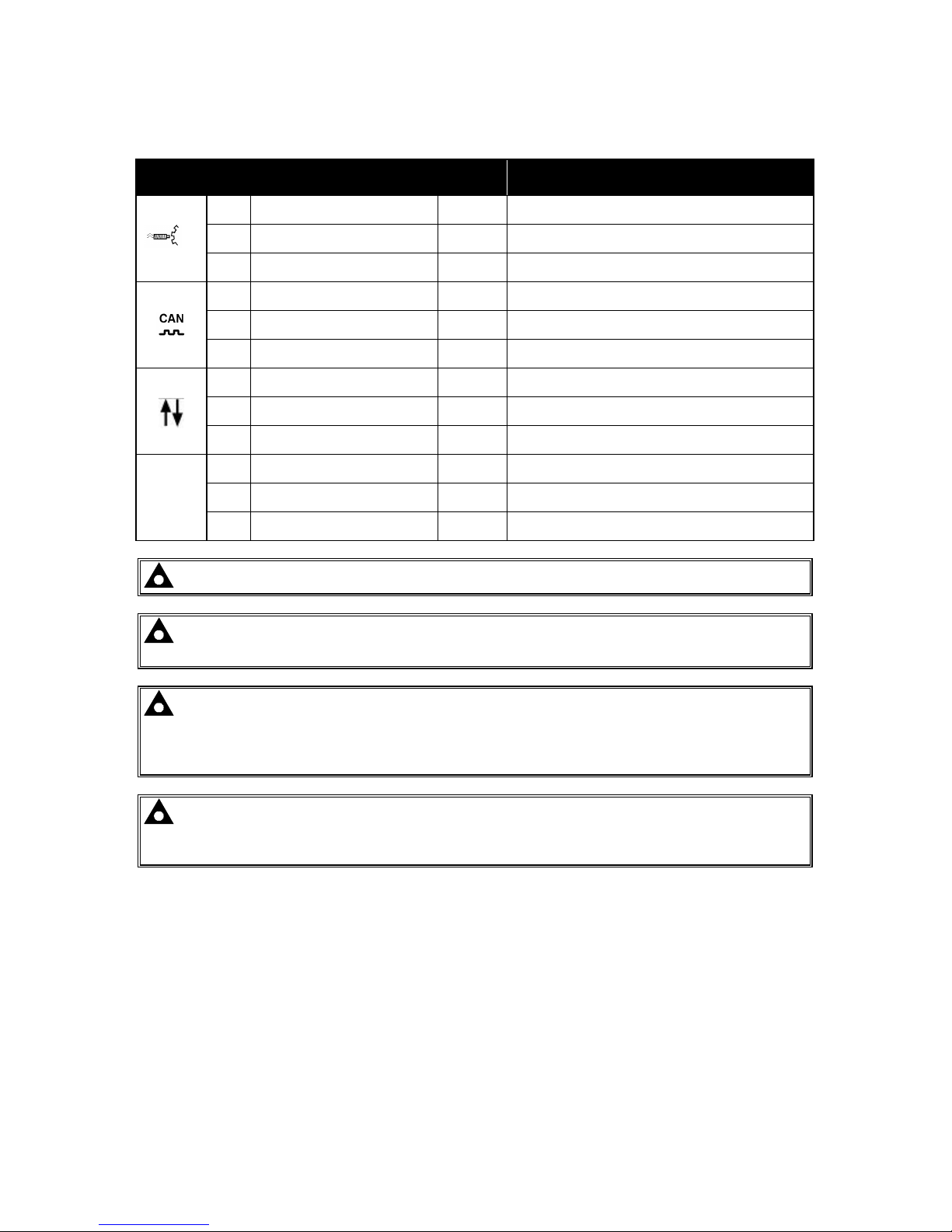
Installation – Terminal Description
40
4.1.3 MAGNETIC PICKUP, CAN AND EXPANSION
PIN
No
DESCRIPTION CABLE
SIZE
NOTES
22 Magnetic pickup Positive
0.5mm²
AWG 20
Connect to Magnetic Pickup device
23 Magnetic pickup Negative
0.5mm²
AWG 20
Connect to Magnetic Pickup device
24 Magnetic pickup screen Shield Connect to ground at one end only
25 CAN port H
0.5mm²
AWG 20
Use only 120Ω CAN approved cable
26 CAN port L
0.5mm²
AWG 20
Use only 120Ω CAN approved cable
27 CAN port Common
0.5mm²
AWG 20
Use only 120Ω CAN approved cable
28 DSENet expansion +
0.5mm²
AWG 20
Use only 120Ω RS485 approved cable
29 DSENet expansion -
0.5mm²
AWG 20
Use only 120Ω RS485 approved cable
30 DSENet expansion SCR
0.5mm²
AWG 20
Use only 120Ω RS485 approved cable
MSC
31 Multiset Comms (MSC) Link H
0.5mm²
AWG 20
Use only 120Ω RS485 approved cable
32 Multiset Comms (MSC) Link L
0.5mm²
AWG 20
Use only 120Ω RS485 approved cable
33 Multiset Comms (MSC) Link SCR
0.5mm²
AWG 20
Use only 120Ω RS485 approved cable
NOTE:- Terminal 34 to 38 are not fitted to the controller
NOTE:- Screened cable must be used for connecting the Magnetic Pickup, ensuring that
the screen is earthed at one end ONLY.
NOTE:- Screened 120ΩΩΩΩ impedance cable specified for use with CAN must be used for the
CAN link and the Multiset comms link.
DSE stock and supply Belden cable 9841 which is a high quality 120ΩΩΩΩ impedance cable
suitable for CAN use (DSE part number 016-030)
NOTE:- When the module is configured for CAN operation, terminals 22, 23 & 24 should
be left unconnected. Engine speed is transmitted to the controller on the CAN link.
Refer to Electronic Engines and DSE Wiring for further information. Part No. 057-004.
Page 41
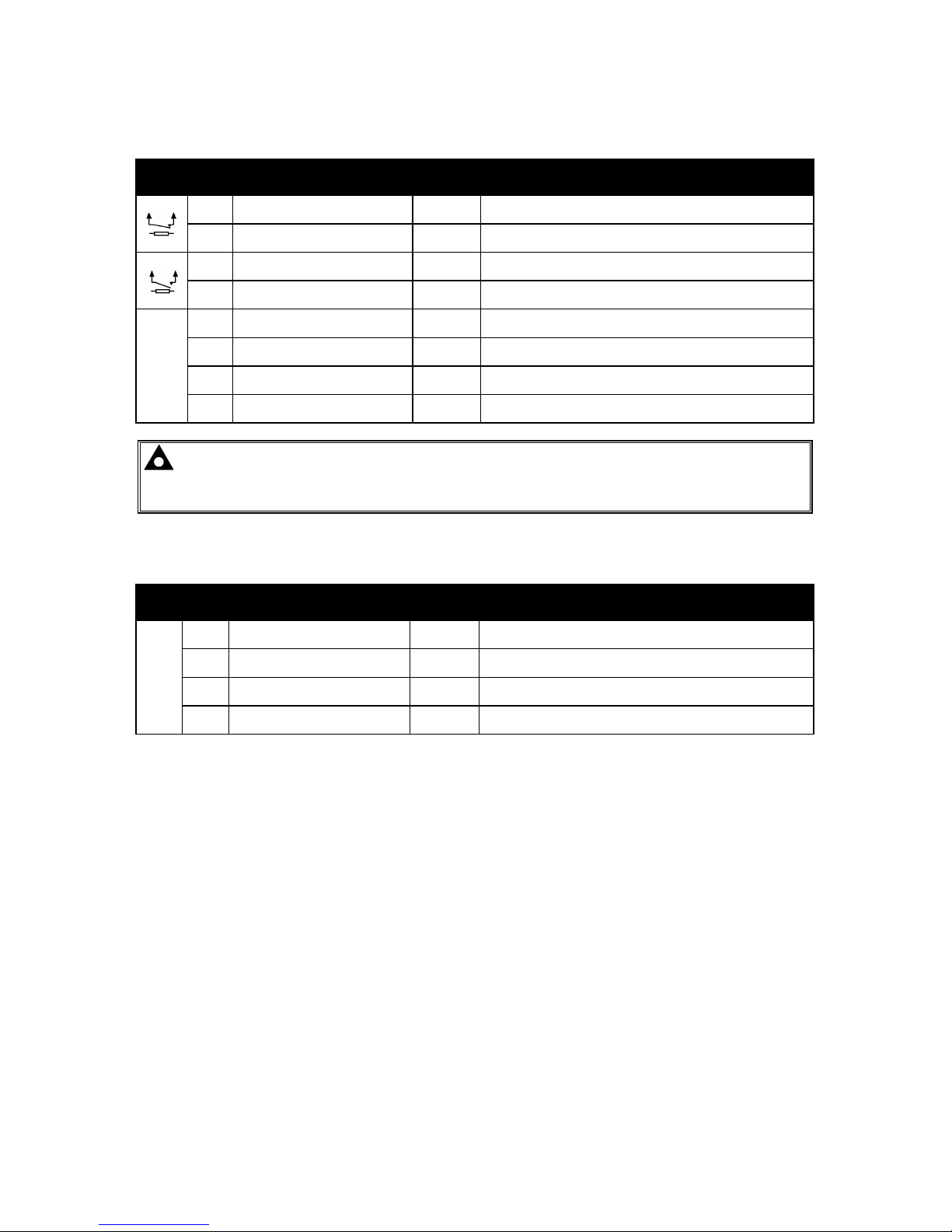
Installation – Terminal Description
41
4.1.4 LOAD SWITCHING AND V1 GENERATOR VOLTAGE SENSING
PIN
No
DESCRIPTION CABLE
SIZE
NOTES
39 Output relay C
1.0mm
AWG 18
Normally configured to control mains contactor coil
(Recommend 10A fuse)
40 Output relay C
1.0mm
AWG 18
Normally configured to control mains contactor coil
41 Output relay D
1.0mm
AWG 18
Normally configured to control generator contactor coil
(Recommend 10A fuse)
42 Output relay D
1.0mm
AWG 18
Normally configured to control generator contactor coil
V1
43
Generator L1 (U) voltage
monitoring
1.0mm²
AWG 18
Connect to generator L1 (U) output (AC)
(Recommend 2A fuse)
44
Generator L2 (V) voltage
monitoring input
1.0mm²
AWG 18
Connect to generator L2 (V) output (AC)
(Recommend 2A fuse)
45
Generator L3 (W) voltage
monitoring input
1.0mm²
AWG 18
Connect to generator L3 (W) output (AC)
(Recommend 2A fuse)
46 Generator Neutral (N) input
1.0mm²
AWG 18
Connect to generator Neutral terminal (AC)
NOTE:- The above table describes connections to a three phase, four wire alternator. For
alternative wiring topologies, please see the ALTERNATIVE AC TOPOLOGIES section of this
manual.
4.1.5 V2 BUS/MAINS VOLTAGE SENSING
PIN
No
DESCRIPTION CABLE
SIZE
NOTES
V2
47
Bus/Mains L1 (R) voltage
monitoring
1.0mm
AWG 18
Connect to Mains L1 (R) incoming supply (AC)
(Recommend 2A fuse)
48
Bus/Mains L2 (S) voltage
monitoring
1.0mm
AWG 18
Connect to Mains L1 (S) incoming supply (AC)
(Recommend 2A fuse)
49
Bus/Mains L3 (T) voltage
monitoring
1.0mm
AWG 18
Connect to Mains L1 (T) incoming supply (AC)
(Recommend 2A fuse)
50 Bus/Mains Neutral (N) input
1.0mm
AWG 18
Connect to Mains N incoming supply (AC)
Page 42
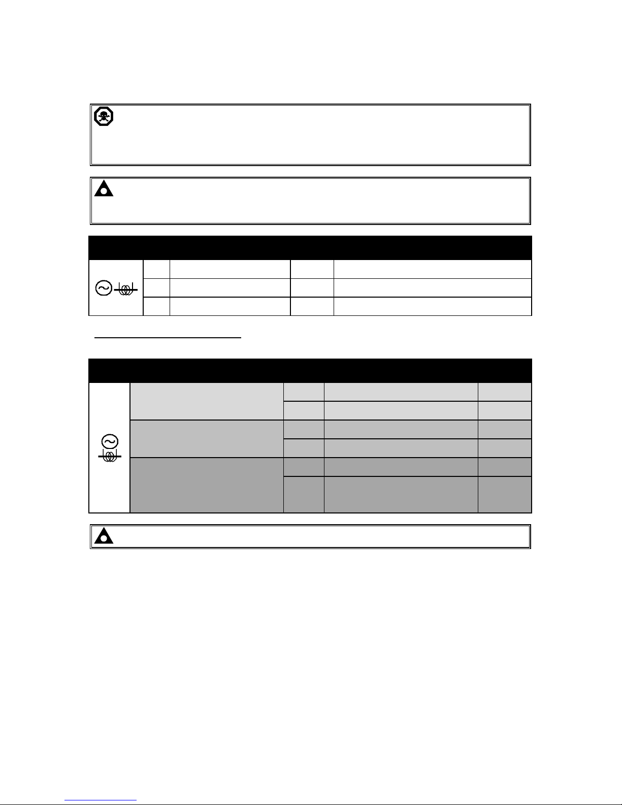
Installation – Terminal Description
42
4.1.6 GENERATOR CURRENT TRANSFORMERS
WARNING!:- Do not disconnect this plug when the CTs are carrying current.
Disconnection will open circuit the secondary of the C.T.’s and dangerous voltages may then
develop. Always ensure the CTs are not carrying current and the CTs are short circuit
connected before making or breaking connections to the module.
NOTE:- The module has a burden of 0.5VA on the CT. Ensure the CT is rated for the
burden of the controller, the cable length being used and any other equipment sharing the
CT. If in doubt, consult your CT supplier.
PIN
No
DESCRIPTION CABLE
SIZE
NOTES
51 CT Secondary for Gen L1
2.5mm²
AWG 13
Connect to s1 secondary of L1 monitoring CT
52 CT Secondary for Gen L2
2.5mm²
AWG 13
Connect to s1 secondary of L2 monitoring CT
53 CT Secondary for Gen L3
2.5mm²
AWG 13
Connect to s1 secondary of L3 monitoring CT
Connection to terminals 54 & 55
The function of terminals 54 and 55 change position depending upon wiring topology as follows:
Topology Pin
No
Description CABLE
SIZE
No earth fault measuring
54 DO NOT CONNECT
55
Connect to s2 of the CTs connected to
L1,L2,L3,N
2.5mm²
AWG 13
Restricted earth fault measuring
54
Connect to s2 of the CTs connected to
L1,L2,L3,N
2.5mm²
AWG 13
55
Connect to s1 of the CT on the neutral
conductor
2.5mm²
AWG 13
Un-restricted earth fault measuring
(Earth fault CT is fitted in the neutral to
earth link)
54
Connect to s1 of the CT on the neutral to
earth conduc tor.
2.5mm²
AWG 13
55
Connect to s2 of the CT on the neutral to
earth link.
Also connect to the s2 of CTs connected to
L1, L2, L3.
2.5mm²
AWG 13
NOTE: - Terminals 56 to 59 are not fitted to the controller.
Page 43
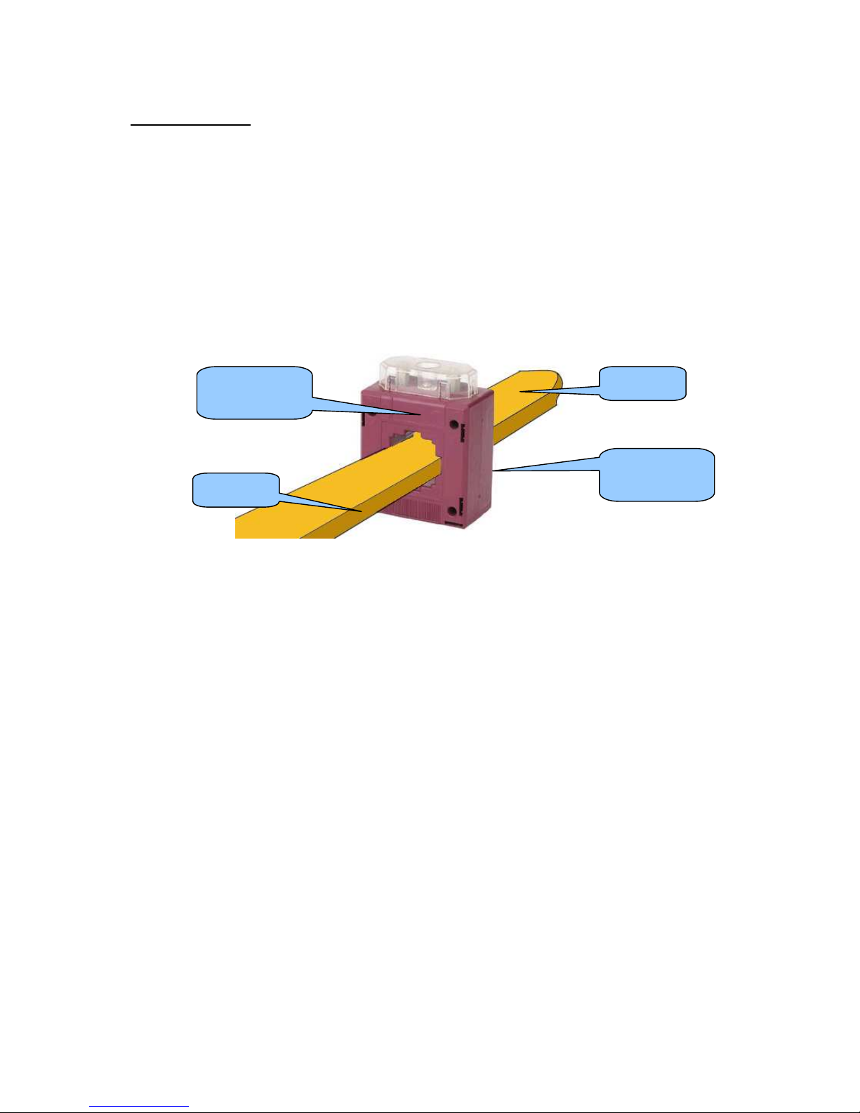
Installation – Terminal Description
43
CT CONNECTIONS
p1,
k
or K is the primary of the CT that ‘points’ towards the GENERATOR
p2,
l
or L is the primary of the CT that ‘points’ towards the LOAD
s1 is the secondary of the CT that connects to the DSE Module’s input for the CT measuring
(I1,I2,I3)
s2 is the secondary of the CT that should be commoned with the s2 connections of all the other CTs
and connected to the CT common terminal of the module.
CT labelled as
p1,
k
or K
CT labelled as
p2,
l
or L
To Supply
To Load
Page 44
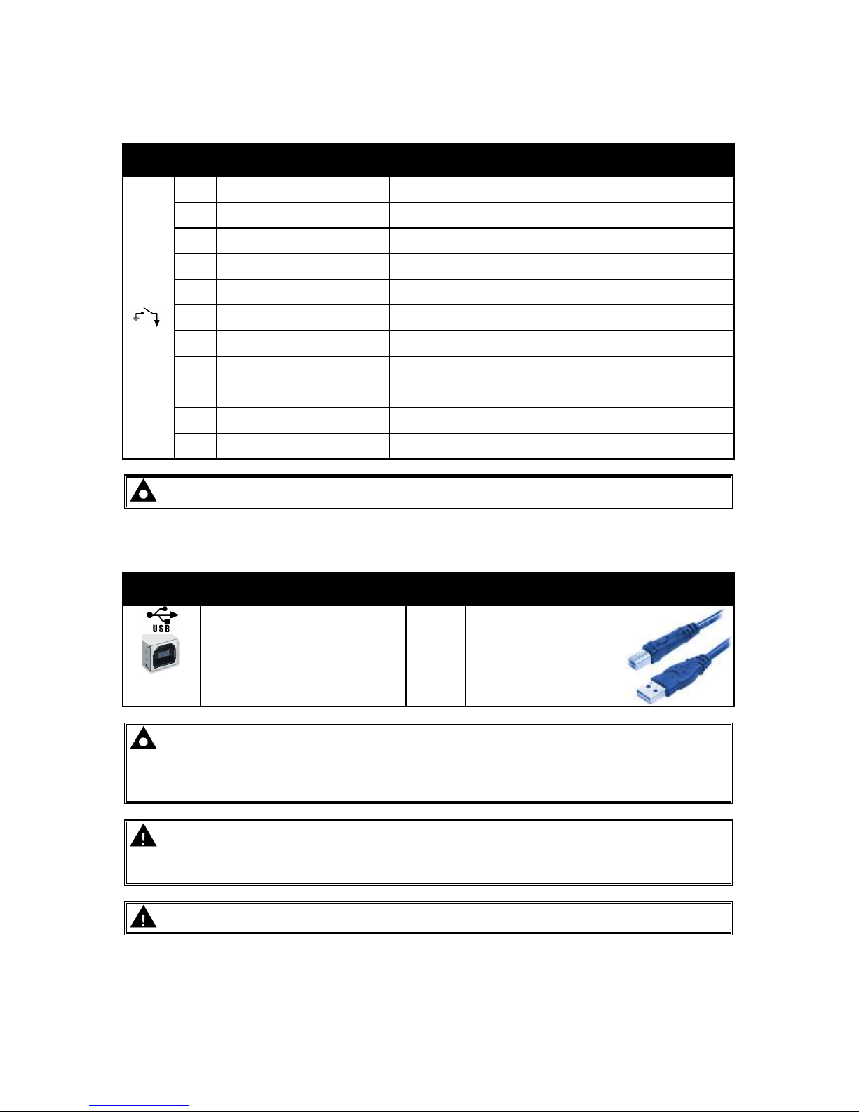
Installation – Terminal Description
44
4.1.7 CONFIGURABLE DIGITAL INPUTS
PIN
No
DESCRIPTION CABLE
SIZE
NOTES
60 Configurable digital input A
0.5mm²
AWG 20
Switch to negative
61 Configurable digital input B
0.5mm²
AWG 20
Switch to negative
62 Configurable digital input C
0.5mm²
AWG 20
Switch to negative
63 Configurable digital input D
0.5mm²
AWG 20
Switch to negative
64 Configurable digital input E
0.5mm²
AWG 20
Switch to negative
65 Configurable digital input F
0.5mm²
AWG 20
Switch to negative
66 Configurable digital input G
0.5mm²
AWG 20
Switch to negative
67 Configurable digital input H
0.5mm²
AWG 20
Switch to negative
68 Configurable digital input I
0.5mm²
AWG 20
Switch to negative
69 Configurable digital input J
0.5mm²
AWG 20
Switch to negative
70 Configurable digital input K
0.5mm²
AWG 20
Switch to negative
NOTE:- See the software manual for full range of configurable outputs available.
4.1.8 PC CONFIGURATION INTERFACE CONNECTOR
DESCRIPTION CABLE
SIZE
NOTES
Socket for connection to PC
with DSE Configuration Suite
Software
0.5mm²
AWG 20
This is a standard USB
type A to type B
connector.
NOTE:- The USB connection cable between the PC and the module must not be extended
beyond 5m (yards). For distances over 5m, it is possible to use a third party USB extender.
Typically, they extend USB up to 50m (yards). The supply and support of this type of
equipment is outside the scope of Deep Sea Electronics PLC.
CAUTION!: Care must be taken not to overload the PCs USB system by connecting more
than the recommended number of USB devices to the PC. For further information, consult
your PC supplier.
CAUTION!: This socket must not be used for any other purpose.
Page 45
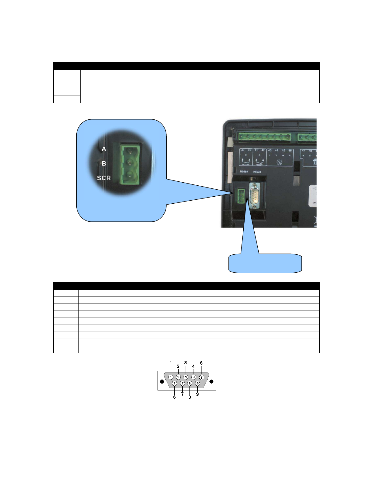
Installation – Terminal Description
45
4.1.9 RS485 CONNECTOR
PIN No NOTES
A (-)
Two core screened twisted pair cable.
120Ω impedance suitable for RS485 use.
Recommended cable type - Belden 9841
Max distance 1200m (1.2km) when using Belden 9841 or direct equivalent.
B (+)
SCR
4.1.10 RS232 CONNECTOR
PIN No NOTES
1 Received Line Signal Detector (Data Carrier Detect)
2 Received Data
3 Transmit Data
4 Data Terminal Ready
5 Signal Ground
6 Data Set Ready
7 Request To Send
8 Clear To Send
9 Ring Indicator
View looking into the male connector on the module
Location of RS232
connector
Location of RS485 connector
Page 46
Installation – Typical Wiring Diagrams
46
4.2 TYPICAL WIRING DIAGRAMS
As every system has different requirements, these diagrams show only a TYPICAL system and do
not intend to show a complete system.
Genset manufacturers and panel builders may use these diagrams as a starting point; however, you
are referred to the completed system diagram provided by your system manufacturer for complete
wiring detail.
Further wiring suggestions are available in the following DSE publications, available at
www.deepseaplc.com to website members.
DSE PART DESCRIPT ION
056-022 Breaker Control (Training guide)
057-004 Electronic Engines and DSE W iring
Page 47
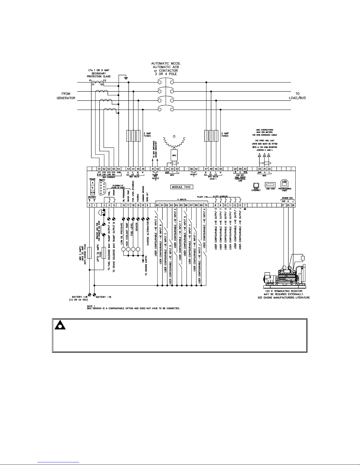
Installation – Typical Wiring Diagrams
47
4.2.1 DSE7410 3 PHASE, 4 WIRE WITH RESTRICTED EARTH FAULT PROTECTION
NOTE:- Earthing the neutral conductor ‘before’ the neutral CT allows the module to read
earth faults ‘after’ the CT only (Restricted to load / downstream of the CT)
Earthing the neutral conductor ‘after’ the neutral CT allows the module to read earth faults
‘before’ the CT only (Restricted to generator / upstream of the CT)
Page 48
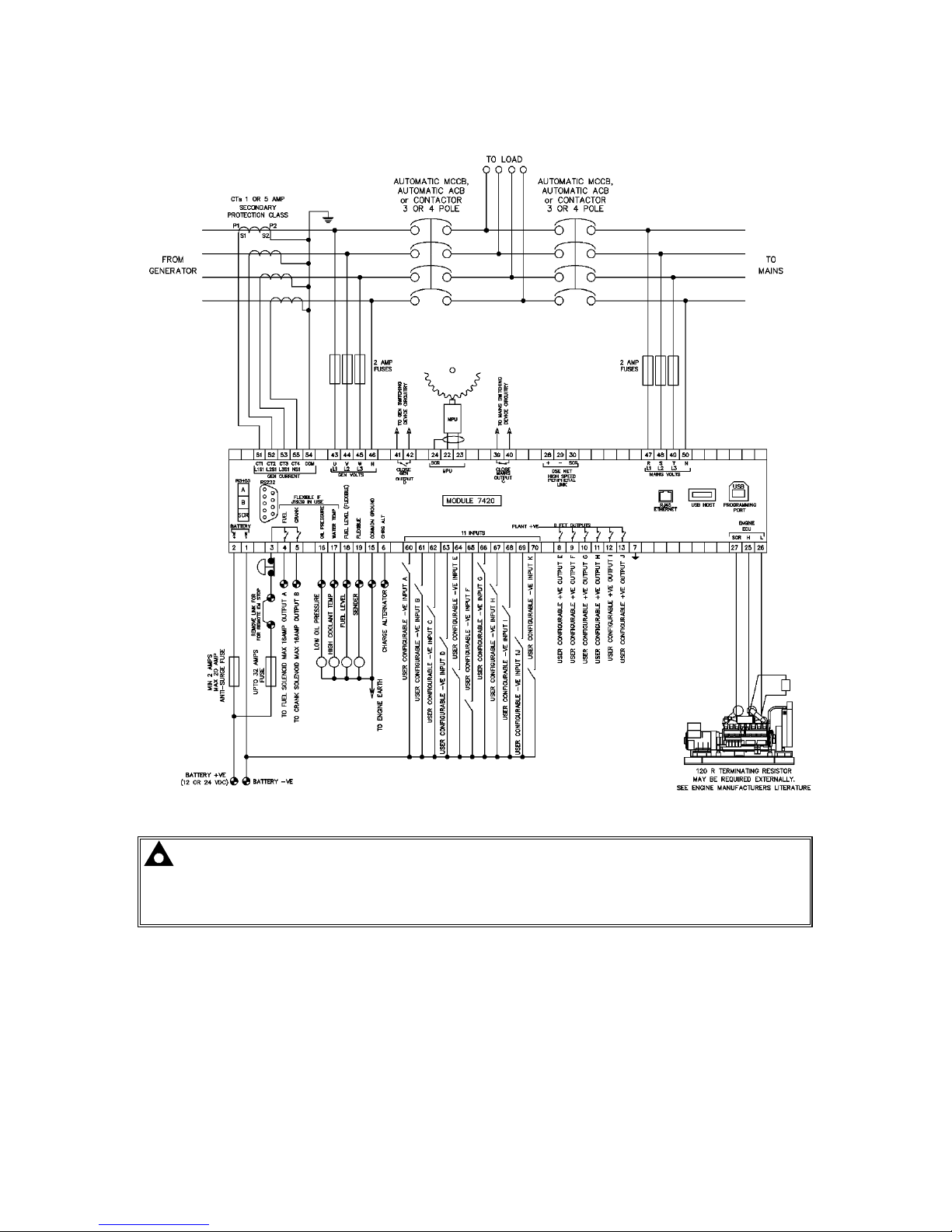
Installation – Typical Wiring Diagrams
48
4.2.2 DSE7420 3 PHASE, 4 WIRE WITH RESTRICTED EARTH FAULT PROTECTION
NOTE:- Earthing the neutral conductor ‘before’ the neutral CT allows the module to read
earth faults ‘after’ the CT only (Restricted to load / downstream of the CT)
Earthing the neutral conductor ‘after’ the neutral CT allows the module to read earth faults
‘before’ the CT only (Restricted to generator / upstream of the CT)
Page 49
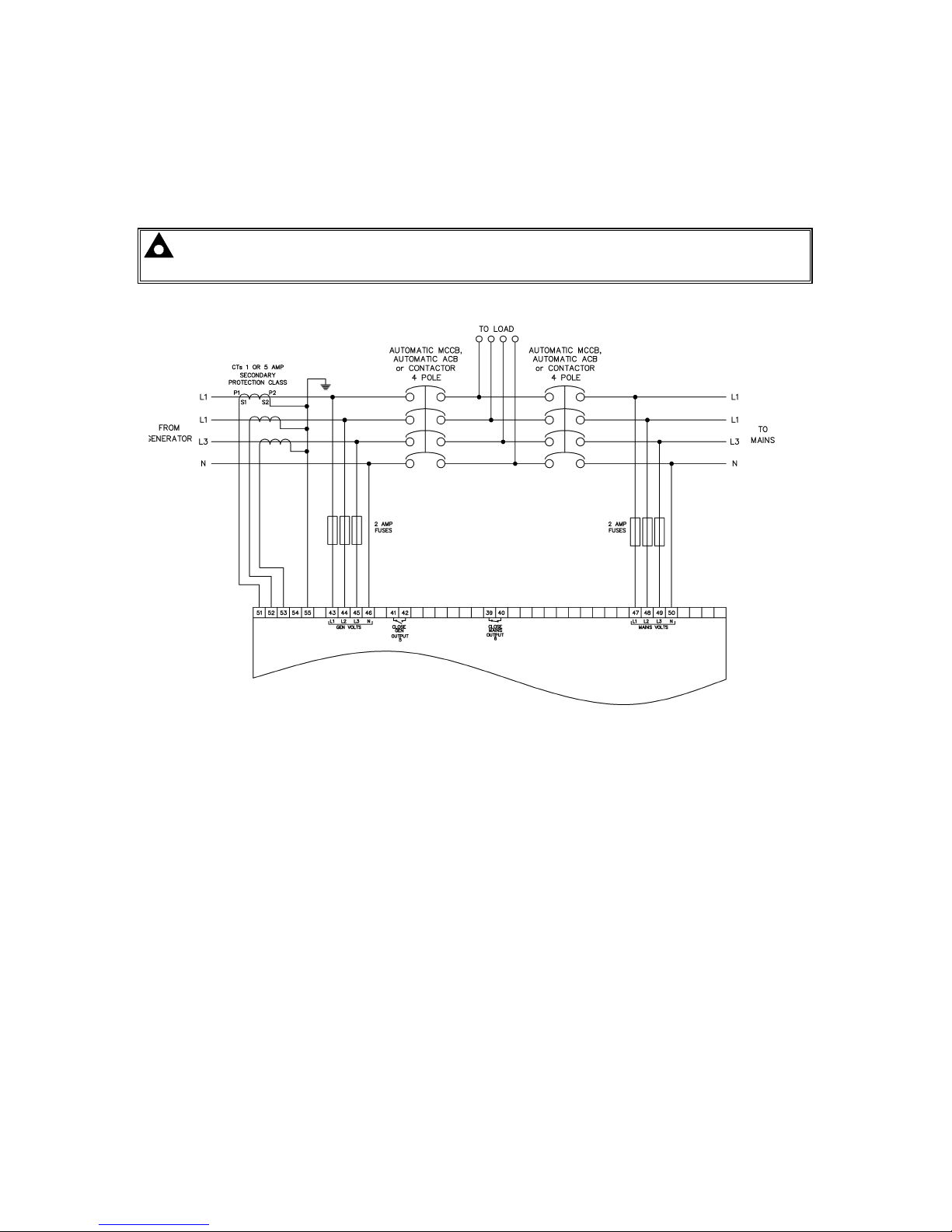
Installation – Typical Wiring Diagrams
49
4.3 ALTERNATIVE TOPOLOGIES
The controller is factory configured to connect to a 3 phase, 4 wire Star connected alternator. This
section details connections for alternative AC topologies. Ensure to configure the controller to suit the
required topology.
NOTE:- Refer to DSE7400 Series Configuration Suite Manual (DSE part 057-160) for further
details on configuring, monitoring and control.
4.3.1 3 PHASE, 4 WIRE WITHOUT EARTH FAULT PROTECTION
Page 50
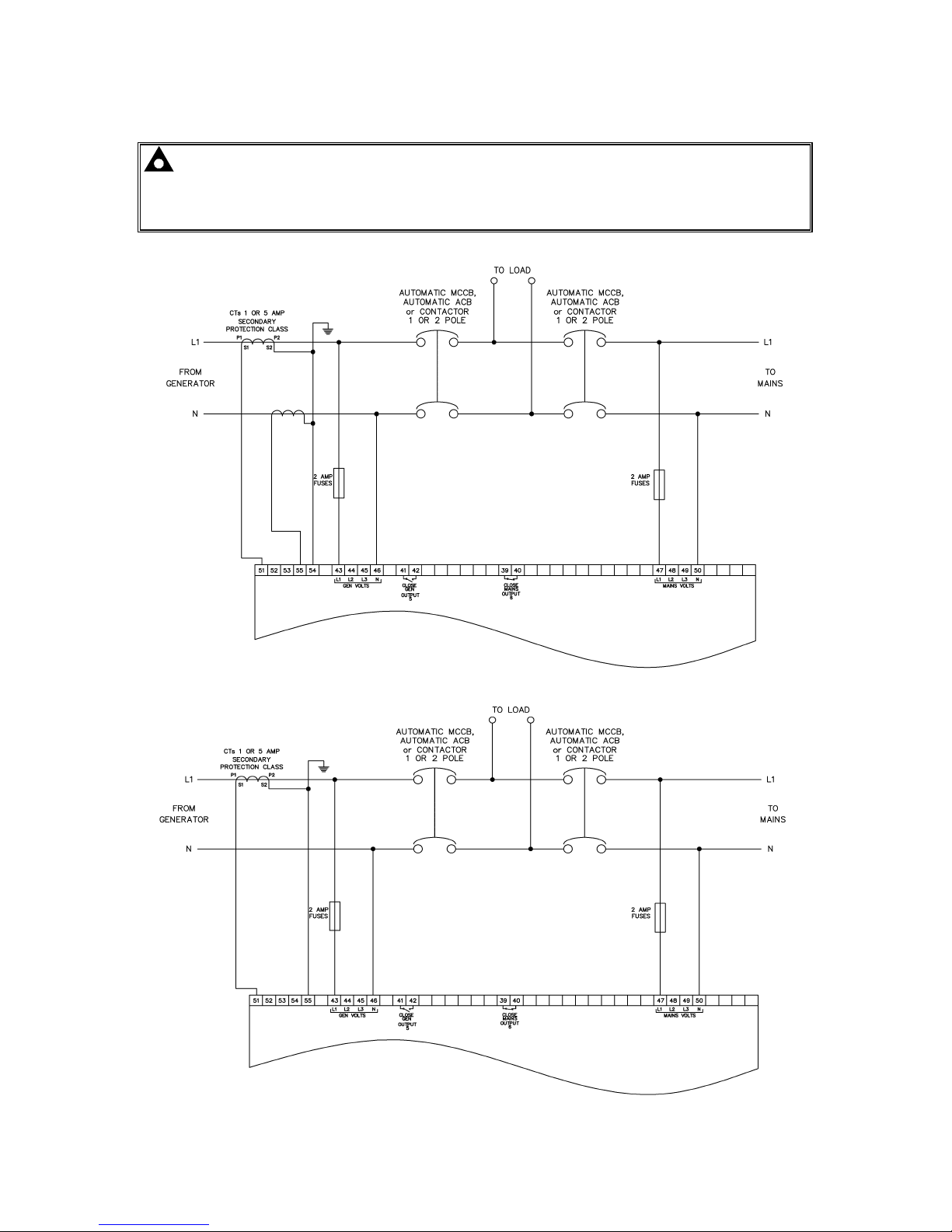
Installation – Typical Wiring Diagrams
50
4.3.2 SINGLE PHASE WITH RESTRICTED EARTH FAULT
NOTE:- Earthing the neutral conductor ‘before’ the neutral CT allows the module to read
earth faults ‘after’ the CT only (Restricted to load / downstream of the CT)
Earthing the neutral conductor ‘after’ the neutral CT allows the module to read earth faults
‘before’ the CT only (Restricted to generator / upstream of the CT)
4.3.3 SINGLE PHASE WITHOUT EARTH FAULT
Page 51
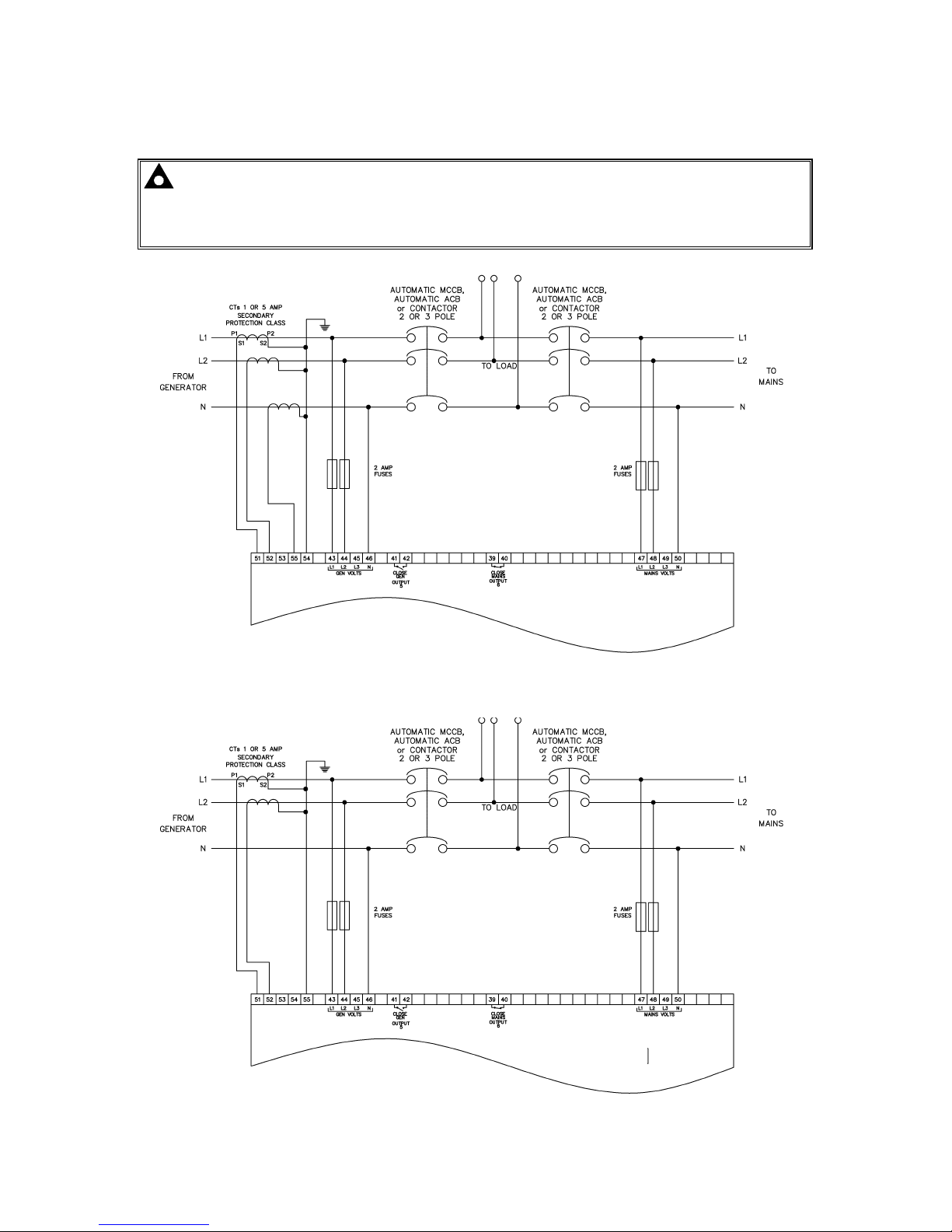
Installation – Typical Wiring Diagrams
51
4.3.4 2 PHASE (L1 & L2) 3 WIRE WITH RESTRICTED EARTH FAULT
NOTE:- Earthing the neutral conductor ‘before’ the neutral CT allows the module to read
earth faults ‘after’ the CT only (Restricted to load / downstream of the CT)
Earthing the neutral conductor ‘after’ the neutral CT allows the module to read earth faults
‘before’ the CT only (Restricted to generator / upstream of the CT)
4.3.5 2 PHASE (L1 & L2) 3 WIRE WITHOUT EARTH FAULT
Page 52
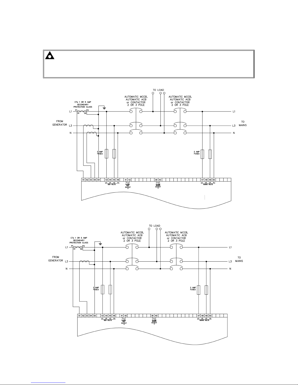
Installation – Typical Wiring Diagrams
52
4.3.6 2 PHASE (L1 & L3) 3 WIRE WITH RESTRICTED EARTH FAULT
NOTE:- Earthing the neutral conductor ‘before’ the neutral CT allows the module to read
earth faults ‘after’ the CT only (Restricted to load / downstream of the CT)
Earthing the neutral conductor ‘after’ the neutral CT allows the module to read earth faults
‘before’ the CT only (Restricted to generator / upstream of the CT)
4.3.7 2 PHASE (L1 & L3) 3 WIRE WITHOUT EARTH FAULT MEASURING
Page 53
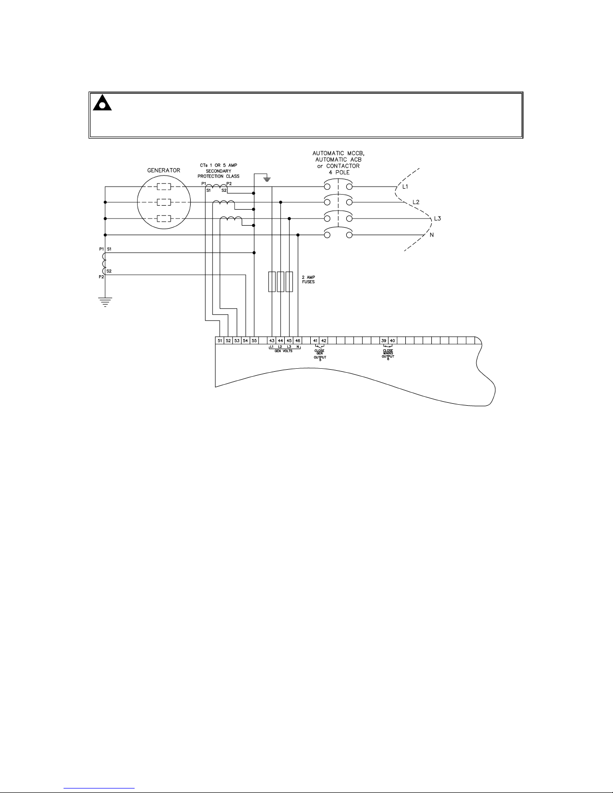
Installation – Typical Wiring Diagrams
53
4.3.8 3 PHASE 4 WIRE WITH UNRESTRICTED EARTH FAULT MEASURING
NOTE:- Unrestricted Earth Fault Protection detects earth faults in the load and in the
generator. Be sure to measure the natural earth fault of the site before deciding upon an earth
fault alarm trip level.
Page 54
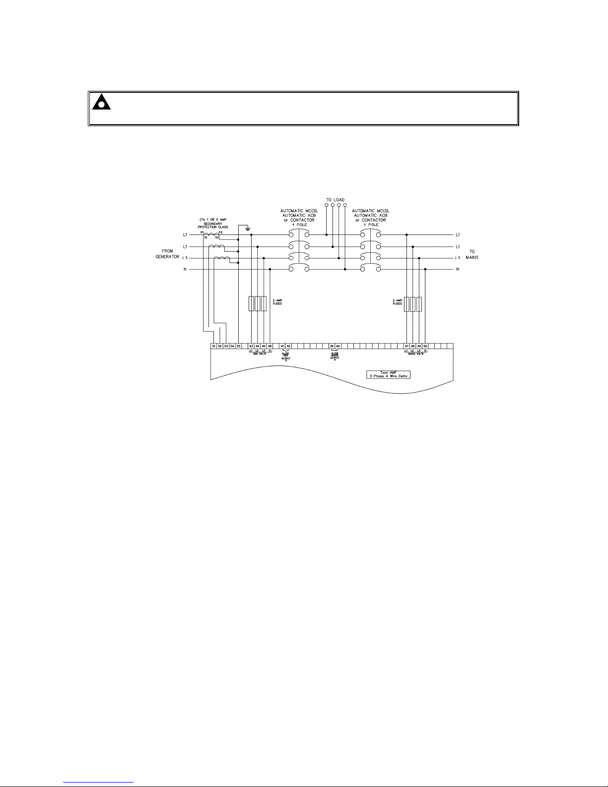
Installation – Typical Wiring Diagrams
54
4.3.9 CT LOCATION
NOTE: CT Location is not applicable to the DSE7410 auto start controllers and is only
available in DSE7420 V1.3 .
There are two possible locations for the current transformers in the system:
1) Generator: The CTs are used to measure and display generator current only. The typical wiring
diagrams in the preceding section all show the CT measuring the generator load. For clarity, an
example is shown below.
2) Load : The CTs are used to measure and display generator current when the generator is on load
and mains current when the mains is on load. The module display automatically changes to
display the current in the relevant instrumentation page. This example shows the CTs in the ‘load’
for a three phase delta system but the same philosophy is applicable to the other topologies.
Page 55
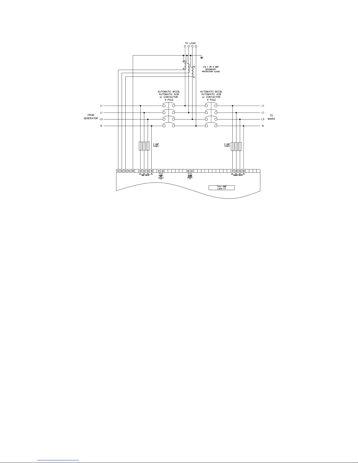
Installation – Typical Wiring Diagrams
55
Page 56

Installation – Typical Wiring Diagrams
56
4.4 EARTH SYSTEMS
4.4.1 NEGATIVE EARTH
The typical wiring diagrams located within this document show connections for a negative earth
system (the battery negative connects to Earth)
4.4.2 POSITIVE EARTH
When using a DSE module with a Positive Earth System (the battery positive connects to Earth), the
following points must be followed:
• Follow the typical wiring diagram as normal for all sections EXCEPT the earth points
• All points shown as Earth on the typical wiring diagram should connect to BATTERY
NEGATIVE (not earth).
4.4.3 FLOATING EARTH
Where neither the battery positive nor battery negative terminals are connected to earth the following
points must to be followed
• Follow the typical wiring diagram as normal for all sections EXCEPT the earth points
• All points shown as Earth on the typical wiring diagram should connect to BATTERY
NEGATIVE (not earth).
4.5 TYPICAL ARRANGEMENT OF DSENET®
Twenty (20) devices can be connected to the DSENet®, made up of the following devices :
Device Max Number
Supported
DSE2130 Input Expansion 4
DSE2131 Ratio-metric Input Expansion 4
DSE2133 RTD/Thermocouple Intput
Expansion
4
DSE2152 Ratio-metric Output Expansion 4
DSE2157 Relay Output Expansion 10
DSE2548 LED Expansion 10
For part numbers of the expansion modules and their documentation, see section entitled DSENet
Expansion Modules elsewhere in this manual.
Page 57
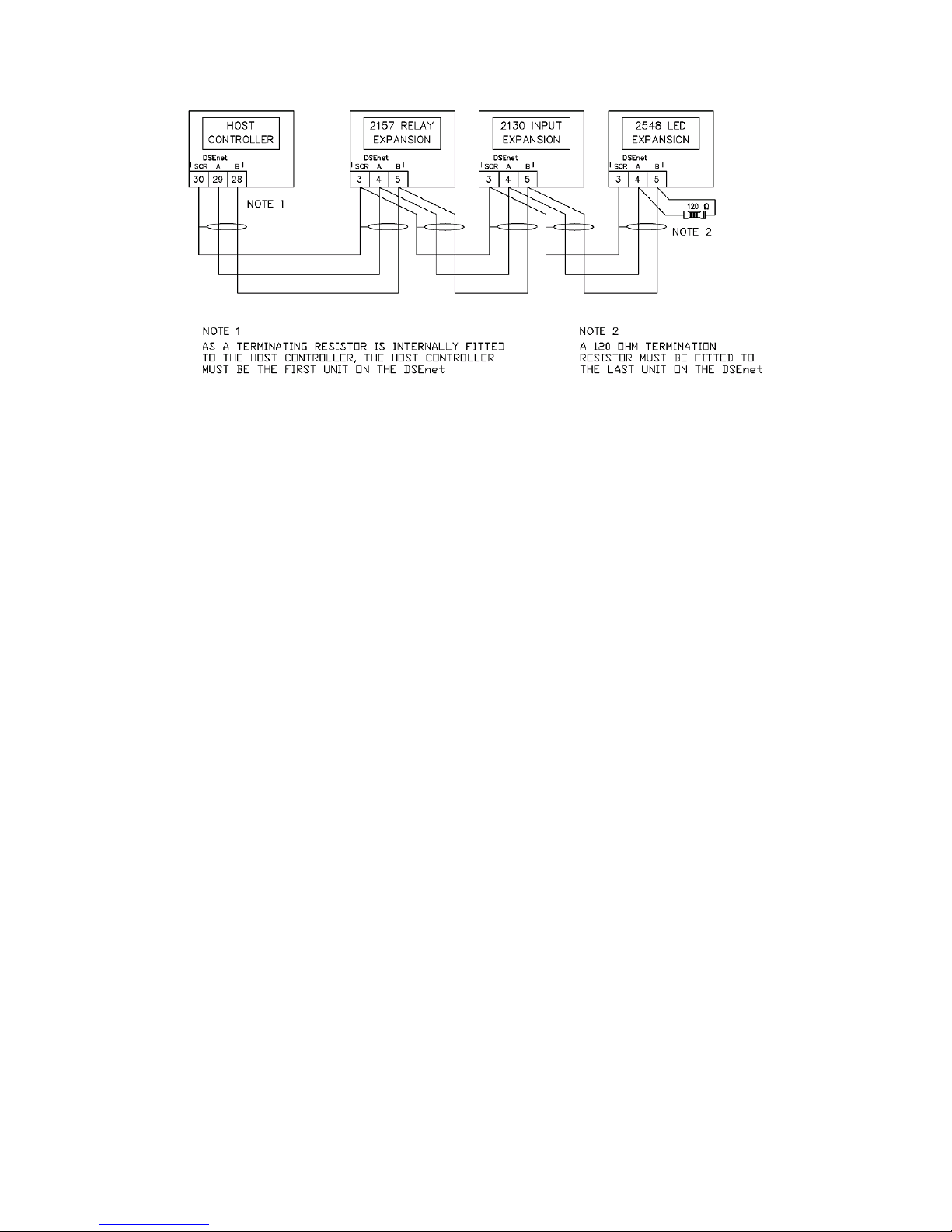
Installation – Typical Wiring Diagrams
57
Page 58
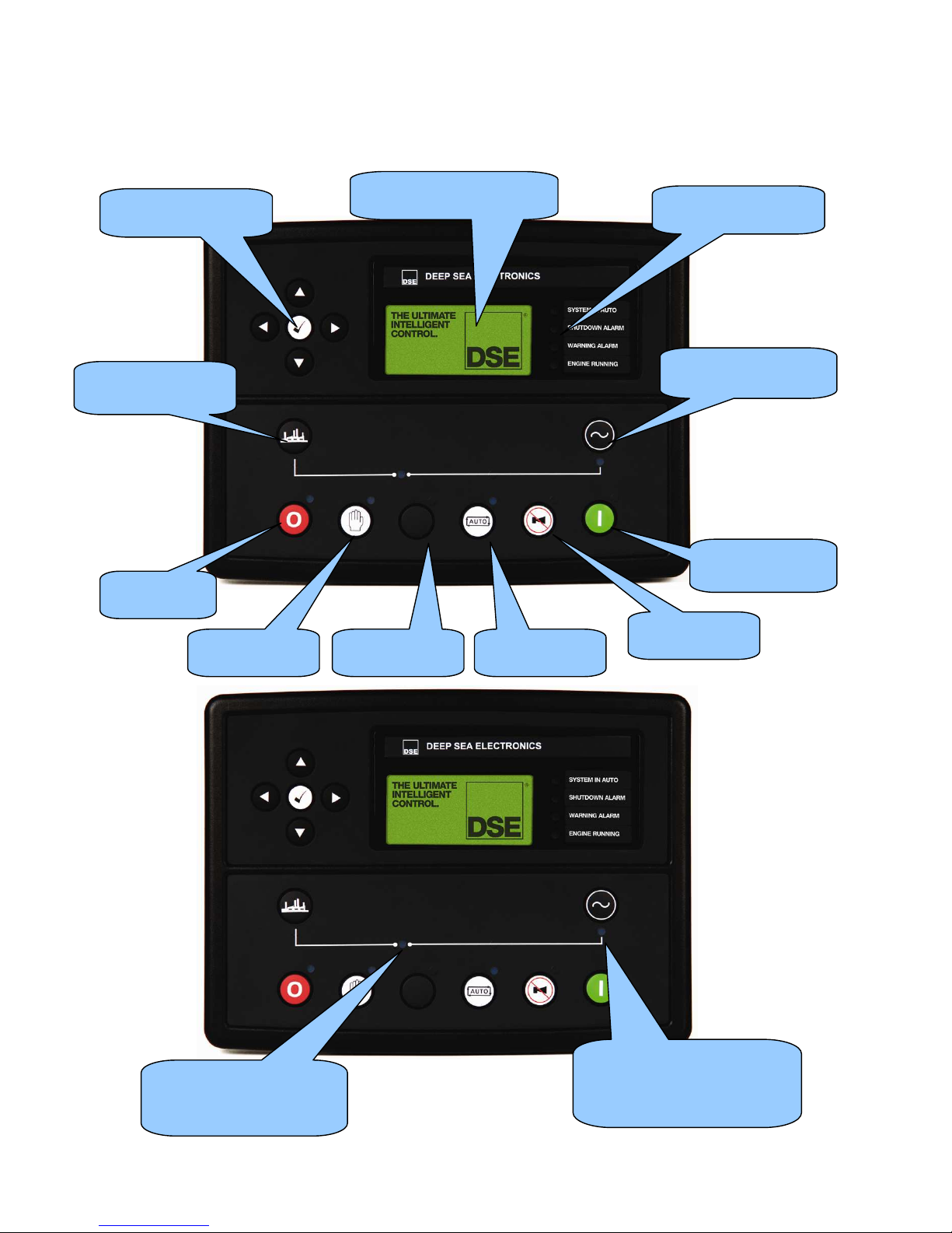
Description Of Controls
58
5 DESCRIPTION OF CONTROLS
5.1 DSE7410 AUTO START CONTROL MODULE
Menu navigation
buttons
Four configurable
LEDs
Select Stop
mode
Select Manual
mode
Select Auto
mode
Mute alarm /
Lamp test
Start engine
(when in manual)
Close Generator
(manual mode only)
Open Generator
(manual mode
Main status and
instrumentation display
Select Test
mode
Close Generator LED.
On When The Generator
Is On Load.
Generator Available LED.
On when the generator is
within limits and able to take
load.
Page 59
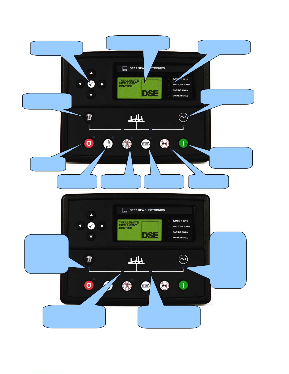
Description Of Controls
59
5.2 DSE7420 AUTO START CONTROL MODULE
Menu navigation
buttons
Four configurable
LEDs
Select Stop
mode
Select Manual
mode
Select Auto
mode
Mute alarm /
Lamp test
Start engine
(when in manual
or Testmode)
Transfer to Generator
(manual mode only)
Transfer to Mains
(manual mode
Main status and
instrumentation display
Select Test
mode
Mains Available
LED.
On when the
mains is within
limits and able to
take load.
Close Mains LED.
On When The Mains Is
On Load.
Close Bus LED.
On When The Bus Is On
Load.
Generator
Available
LED.
On when the
generator is
within limits
and able to
take load.
Page 60
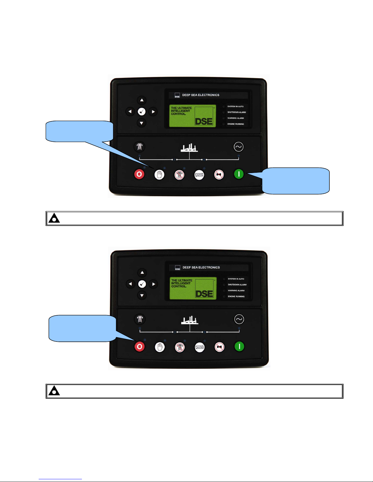
Description Of Controls
60
5.3 QUICKSTART GUIDE
This section provides a quick start guide to the module’s operation.
5.3.1 STARTING THE ENGINE
NOTE:- For further details, see the section entitled ‘OPERATION’ elsewhere in this manual.
5.3.2 STOPPING THE ENGINE
NOTE:- For further details, see the section entitled ‘OPERATION’ elsewhere in this manual.
Select Stop/Reset
mode. The generator
is stopped.
First, select manual
mode
then press the
Start button to crank
the engine.
Page 61
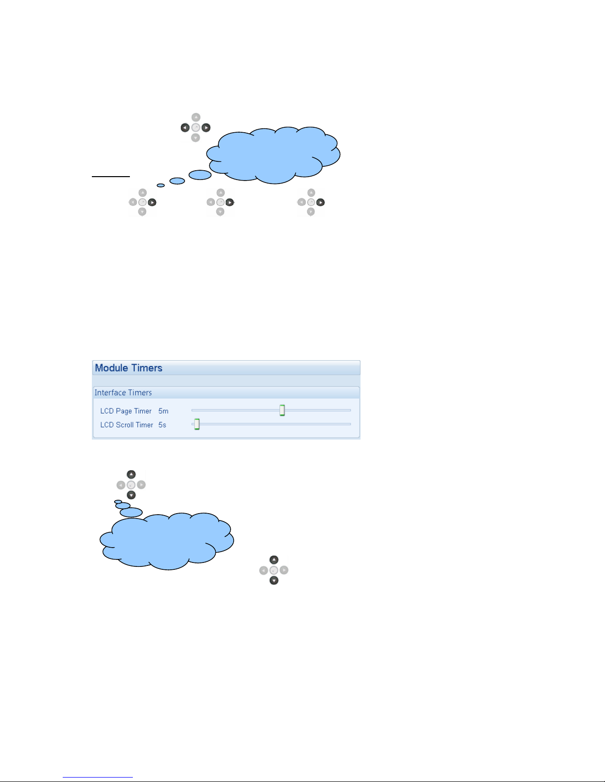
Viewing The Instrument Pages
61
5.4 VIEWING THE INSTRUMENT PAGES
It is possible to scroll to display the different pages of information by repeatedly operating the next /
previous page buttons
.
Example
Status
Engine
Generator
And so on until the last page is reached.
A Further press of the scroll right button
returns the display to the Status page.
The complete order and contents of each information page are given in the following sections
Once selected the page will remain on the LCD display until the user selects a different page, or after
an extended period of inactivity (LCD Page Timer), the module will revert to the status display.
If no buttons are pressed upon entering an instrumentation page, the instruments will be displayed
automatically subject to the setting of the LCD Scroll Timer.
The LCD Page and LCD Scroll timers are configurable using the DSE Configuration Suite Software or
by using the Front Panel Editor.
The screenshot shows the factory
settings for the timers, taken from
the DSE Configuration Suite
Software.
Alternatively, to scroll manually through all instruments on the currently selected page, press the
scroll
buttons. The ‘autoscroll’ is disabled.
To re-enable ‘autoscroll’ press the scroll
buttons to scroll to the ‘title’ of the instrumentation
page (ie Engine). A short time later (the duration of the LCD Scroll Timer), the instrumentation
display will begin to autoscroll.
When scrolling manually, the display will automatically return to the Status page if no buttons are
pressed for the duration of the configurable LCD Page Timer.
If an alarm becomes active while viewing the status page, the display shows the Alarms page to draw
the operator’s attention to the alarm condition.
If yo u wan t to vi ew on e of t he
instruments tow ards the end of
the list, it may be qui cker to
scroll up through the
instruments rather than down!
If yo u wan t to vi ew on e of t he
instrument pages towards the
end of the list, it may be
quicker to scroll left through
the pages rather than right!
Page 62
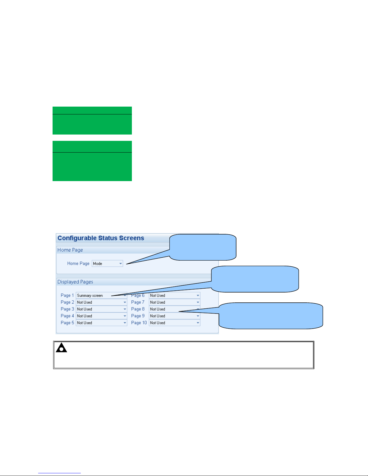
Viewing The Instrument Pages
62
5.4.1 STATUS
This is the ‘home’ page, the page that is displayed when no other page has been selected, and the
page that is automatically displayed after a period of inactivity (LCD Page Timer) of the module
control buttons.
This page will change with the action of the controller , when on gen generator parameters will be
seen and when changing to mains the mains parameters will be shown.
Status 22:31
Status 22:31Status 22:31
Status 22:31
Factory setting of Status screen showing engine stopped...
Generator at Rest
Generator at RestGenerator at Rest
Generator at Rest
Stop Mode
Stop ModeStop Mode
Stop Mode
Safety on
Safety onSafety on
Safety on
Delay
Delay Delay
Delay
00:04
00:0400:04
00:04
...and engine running
LLLL----N 215V 43A
N 215V 43AN 215V 43A
N 215V 43A
LLLL----L 373V
L 373V L 373V
L 373V
47.5Hz
47.5Hz47.5Hz
47.5Hz
0kW
0kW 0kW
0kW
0.0pf
0.0pf0.0pf
0.0pf
The contents of this display may vary depending upon configuration by the generator manufacturer /
supplier.
The display above is achieved with the factory settings, shown below in the DSE Configuration suite
software:
NOTE:- The following sections detail instrumentation pages, accessible using the scroll
left and right buttons, regardless of what pages are configured to be displayed on the ‘status’
screen.
‘Stop Mode’ etc is
displayed on the
Home Page
With a summary of the
instrumentation shown when
the engine is running.
Other pages can be configured to
be shown, automatically scrolling
when the set is running.
Page 63
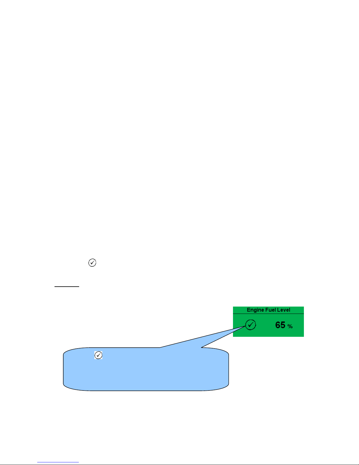
Viewing The Instrument Pages
63
5.4.2 ENGINE
Contains instrumentation gathered about the engine itself, some of which may be obtained using the
CAN or other electronic engine link.
• Engine Speed
• Oil Pressure
• Coolant Temperature
• Engine Battery Volts
• Engine Run Time
• Engine Fuel Level
• Oil Temperature*
• Coolant Pressure*
• Inlet Temperature*
• Exhaust Temperature*
• Fuel Temperature*
• Turbo Pressure*
• Fuel Pressure*
• Fuel Consumption*
• Fuel Used*
• Fuel Level*
• Auxiliary Sensors (If fitted and configured)
• Engine Maintenance Due (If configured)
• Engine ECU Link*
*When connected to suitably configured and compatible engine ECU. For details of supported
engines see ‘Electronic Engines and DSE wiring’ (DSE Part number 057-004).
• Tier 4 engine information will also be available if used with a Tier 4 suitable engine / ECU.
Depending upon configuration and instrument function, some of the instrumentation items may
include a tick
icon beside them. This denotes a further function is available, detailed in the
‘operation’ section of this document.
Example:
The tick icon denotes that manual fuel pump control is
enabled in this system.
Press and hold to start the fuel transfer pump, release to
stop the pump. This is detailed further in the section
entitled ‘operation’ elsewhere in this document.
Page 64
Viewing The Instrument Pages
64
5.4.3 GENERATOR
Contains electrical values of the generator (alternator), measured or derived from the module’s
voltage and current inputs.
• Generator Voltage (ph-N)
• Generator Voltage (ph-ph)
• Generator Frequency
• Generator Current
• Generator Earth Current
• Generator Load %
• Generator Load (kW)
• Generator Load (kVA)
• Generator Power Factor
• Generator Power Factor Average
• Generator Load (kVAr)
• Generator Load (kWh, kVAh, kVArh)
• Generator Phase Sequence
• Generator Config (Nominals)
• Generator Active Config
5.4.4 BUS (DSE7410 ONLY)
• Bus Voltage (ph-N)
• Bus Voltage (ph-ph)
• Bus Frequency
5.4.5 MAINS (DSE7420 ONLY)
NOTE: Mains current and power measurement is is only available in DSE7420 V1.3 when
the CT location is selected to be the load.
• Mains Voltage (ph-N)
• Mains Voltage (ph-ph)
• Mains Frequency
• Mains Current
• Mains Load %
• Mains Load (kW)
• Mains Load (kVA)
• Mains Power Factor
• Mains Power Factor Average
• Mains Load (kVAr)
• Mains Load (kWh, kVAh, kVArh)
Page 65
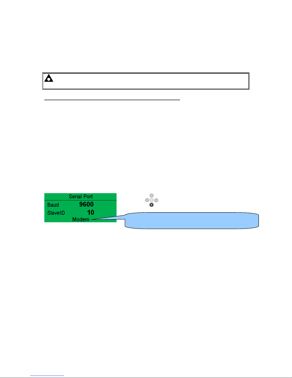
Viewing The Instrument Pages
65
5.4.6 RS232 SERIAL PORT
This section is included to give information about the RS232 serial port and external modem (if
connected).
The items displayed on this page will change depending upon configuration of the module. You are
referred to your system supplier for further details.
NOTE:- Factory Default settings are for the RS232 port to be enabled with no modem
connected, operating at 19200 baud, modbus slave address 10.
Example 1 – Module connected to an RS232 telephone modem.
When the module is powered up, it will send ‘initialisation strings’ to the connected modem. It is
important therefore that the modem is already powered, or is powered up at the same time as the
module. At regular intervals after power up, the modem is reset, and reinitialised, to ensure the
modem does not ‘hang up’.
If the module does not correctly communicate with the modem, “Modem initialising’ appears on the
Serial Port instrument screen as shown overleaf.
If the module is set for “incoming calls” or for “incoming and outgoing calls”, then if the modem is
dialled, it will answer after two rings (using the factory setting ‘initialisation strings)’. Once the call is
established, all data is passed from the dialling PC and the module.
If the module is set for “outgoing calls” or for “incoming and outgoing calls”, then the module will dial
out whenever an alarm is generated. Note that not all alarms will generate a dial out; this is
dependant upon module configuration of the event log. Any item configured to appear in the event
log will cause a dial out.
Press down to view the modem status....
Indicates that a modem is configured. Shows ‘RS232’ if no
modem is configured.
Page 66
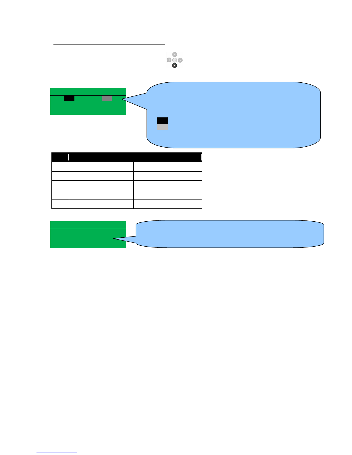
Viewing The Instrument Pages
66
Example 1 continued – Modem diagnostics
Modem diagnostic screens are included; press when viewing the RS232 Serial Port instrument
to cycle the available screens. If you are experiencing modem communication problems, this
information will aid troubleshooting.
Serial Port
Serial PortSerial Port
Serial Port
RTS
RTSRTS
RTS
CTS
CTSCTS
CTS
DSR
DSRDSR
DSR
DTR
DTRDTR
DTR
DCD
DCDDCD
DCD
Line Description
RTS Request To Send Flow control
CTS Clear To Send Flow control
DSR Data Set Ready Ready to communicate
DTR Data Terminal Ready Ready to communicate
DCD Data Carrier Detect Modem is connected
Modem Commands
Modem CommandsModem Commands
Modem Commands
Rx: OK
Rx: OKRx: OK
Rx: OK
Tx: AT+IPR=9600
Tx: AT+IPR=9600Tx: AT+IPR=9600
Tx: AT+IPR=9600
Rx: OK
Rx: OKRx: OK
Rx: OK
Shows the state of the modem communication lines. These can
help diagnose connection problems.
Example:
RTS A dark background shows the line is active.
RTS a grey background shows that the line is toggling high and
low.
RTS No background indicates that the line is inactive
Shows the last command sent to the modem and the result of the
command.
Page 67
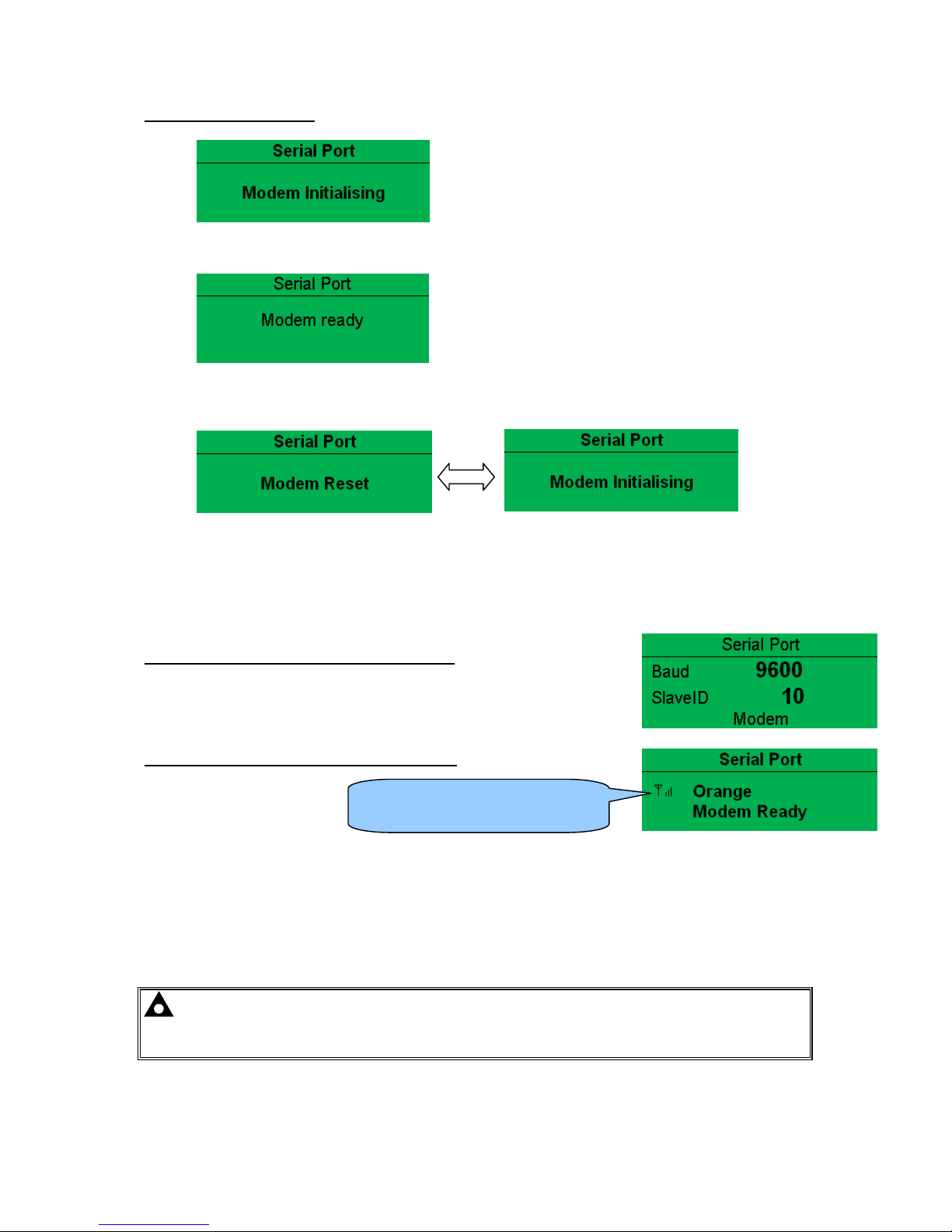
Viewing The Instrument Pages
67
Modem Setup Sequence
1)
If the Modem and module communicate successfully:
2)
In case of communication failure between the modem and module, the modem is automatically reset
and initialisation is attempted once more:
3)
In the case of a module that is unable to communicate with the modem, the display will
continuously cycle between ‘Modem Reset’ and ‘Modem Initialising’ as the module resets the
modem and attempts to communicate with it again, this will continue until correct
communication is established with the modem.
In this instance, you should check connections and verify the modem operation.
Example 2 – Module connected to a modem.
Example 3 – Modem status of a GSM modem
Many GSM modems are fitted with a status LED to show operator cell status and ringing indicator.
These can be a useful troubleshooting tool.
In the case of GSM connection problems, try calling the DATA number of the SIMCARD with an
ordinary telephone. There should be two rings, followed by the modem answering the call and then
‘squealing’. If this does not happen, you should check all modem connections and double check with
the SIM provider that it is a DATA SIM and can operate as a data modem. DATA is NOT the same as
FAX or GPRS and is often called Circuit Switched Data (CSD) by the SIM provider.
NOTE: In the case of GSM modems, it is important that a DATA ENABLED SIM is used.
This is often a different number than the ‘voice number’ and is often called Circuit Switched
Data (CSD) by the SIM provider.
If the GSM modem is not purchased from DSE, ensure that it has been correctly set to operate at
9600 baud.
Currently connected GSM
operator and signal strength.
Page 68
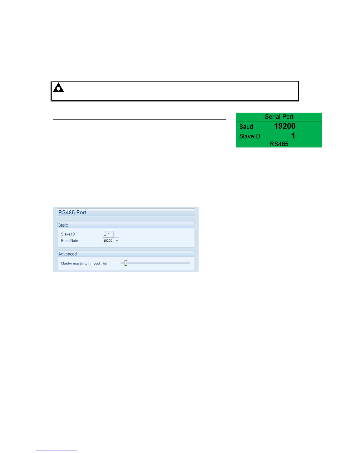
Viewing The Instrument Pages
68
5.4.7 RS485 SERIAL PORT
This section is included to give information about the currently selected serial port and external
modem (if connected).
The items displayed on this page will change depending upon configuration of the module. You are
referred to your system supplier for further details.
NOTE:- Factory Default settings are for the RS485 port to operating at 19200 baud,
modbus slave address 10.
Module RS485 port configured for connection to a modbus master.
The modules operate as a modbus RTU slave device.
In a modbus system, there can be only one Master, typically a PLC, HMI
system or PC SCADA system.
This master requests for information from the modbus slave (The module) and may (in control
systems) also send request to change operating modes etc. Unless the Master makes a request, the
slav e is ‘quiet’ on the data link.
The factory settings are for the module to communicate at 19200 baud, modbus slave address 10.
To use the RS485 port, ensure that ‘port usage’ is correctly set using the DSE Configuration Suite
Software.
Required settings are shown below.
‘Master inactivity timeout’ should be set to at least twice the value of the system scan time. For
example if a modbus master PLC requests data from the module once per second, the timeout
should be set to at least 2 seconds.
The DSE Modbus Gencomm document containing register mappings inside the DSE module is
available upon request from [email protected]. Email your request along with the serial
number of your DSE module to ensure the correct information is sent to you.
Page 69
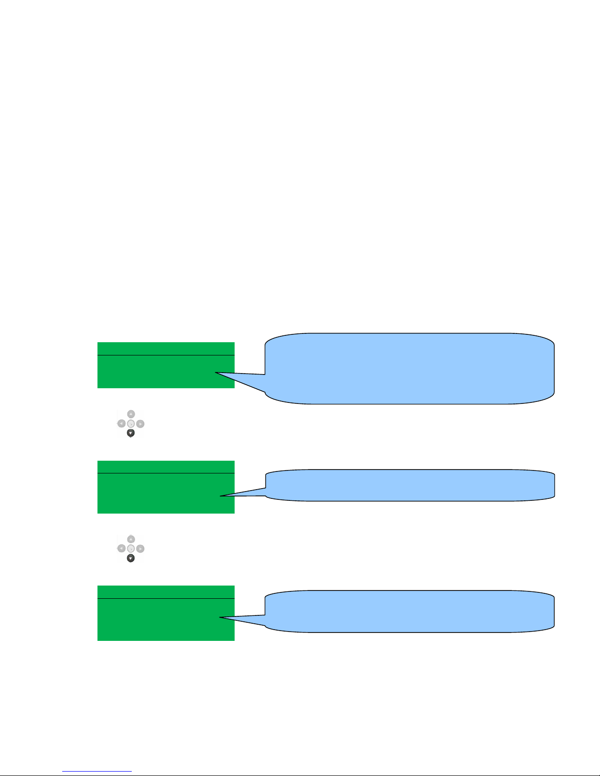
Viewing The Instrument Pages
69
Typical requests (using Pseudo code)
BatteryVoltage=ReadRegister(10,0405,1)
: reads register (hex) 0405 as a single register (battery volts)
from slave address 10.
WriteRegister(10,1008,2,35701, 65535-35701)
: Puts the module into AUTO mode by writing to (hex)
register 1008, the values 35701 (auto mode) and register 1009 the value 65535-35701 (the bitwise
opposite of auto mode)
Shutdown=(ReadRegister(10,0306,1) >> 12) & 1)
: reads (hex) 0306 and looks at bit 13 (shutdown alarm
present)
Warning=(ReadRegister(10,0306,1) >> 11) & 1)
: reads (hex) 0306 and looks at bit 12 (Warning alarm
present)
ElectricalTrip=(ReadRegister(10,0306,1) >> 10) & 1)
: reads (hex) 0306 and looks at bit 11 (Electrical
Trip alarm present)
ControlMode=ReadRegister(10,0304,2);
reads (hex) register 0304 (control mode).
5.4.8 ABOUT
Contains important information about the module and the firmware versions. This information may be
asked for when contacting DSE Technical Support Department for advice.
About
Variant 7420
Application V4.4.6
USB ID BC614E
Press to access more information about the module.
About
Bootloader V1.3.4
Analogue V2.0.0
Press to access more information about the module.
About
Engine
Type
Volvo EMS2b
Version V1.18
• Variant (7410 or 7420)
• Application Version – The version of the module’s main
firmware file (Updatable using the Firmware Update
Wizard in the DSE Configuration Suite Software).
• USB ID – Unique identifier for PC USB connection
• Bootloader - Firmware Update bootloader software
version
• Engine Type – The type of engine or ECU file which is
configured within the module.
• Version
– Engine type file version.
Page 70
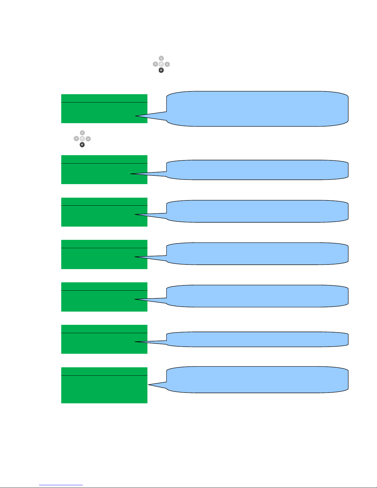
Viewing The Instrument Pages
70
5.4.8.1 ETHERNET PAGES
Whilst in the ‘ABOUT’ section, press to access more information about the network settings.
Network settings change be configured using DSE Configuration Suite Software. The module must be
rebooted for the changes to take effect.
Network
IP Address
192.168.50.76
DHCP Disabled
Press to access more information about the network settings.
Network
Subnet Mask
255.255.255.0
Network
Gateway Address
192.168.49.76
Network
DNS Address
192.168.88.99
Network
MAC Address
E8.A4.C1.0.A.C2
DHCP
Host
Domain
Vender
MODBUS Over IP
TCP Port 502
Pref IP 192.168.20.1
1
• IP Address – The configured network IP address of the
module
• DHCP – Dynamic Host Configuration Protocol (DHCP)
has been enabled or disabled in the modules
• Subnet Mask – The configured network subnet mask of
the module.
• Gateway Address – The configured network gateway
address of the module.
• DNS Address – The configured network DNS address of
the module.
• MAC Address – The MAC address of the module, this
cannot be changed and is unique to each module.
• DHCP – The DHCP settings of module if configured.
• TCP Port – The MODBUS TCP communication port
number.
• Pref IP
– The preferred IP address.
Page 71
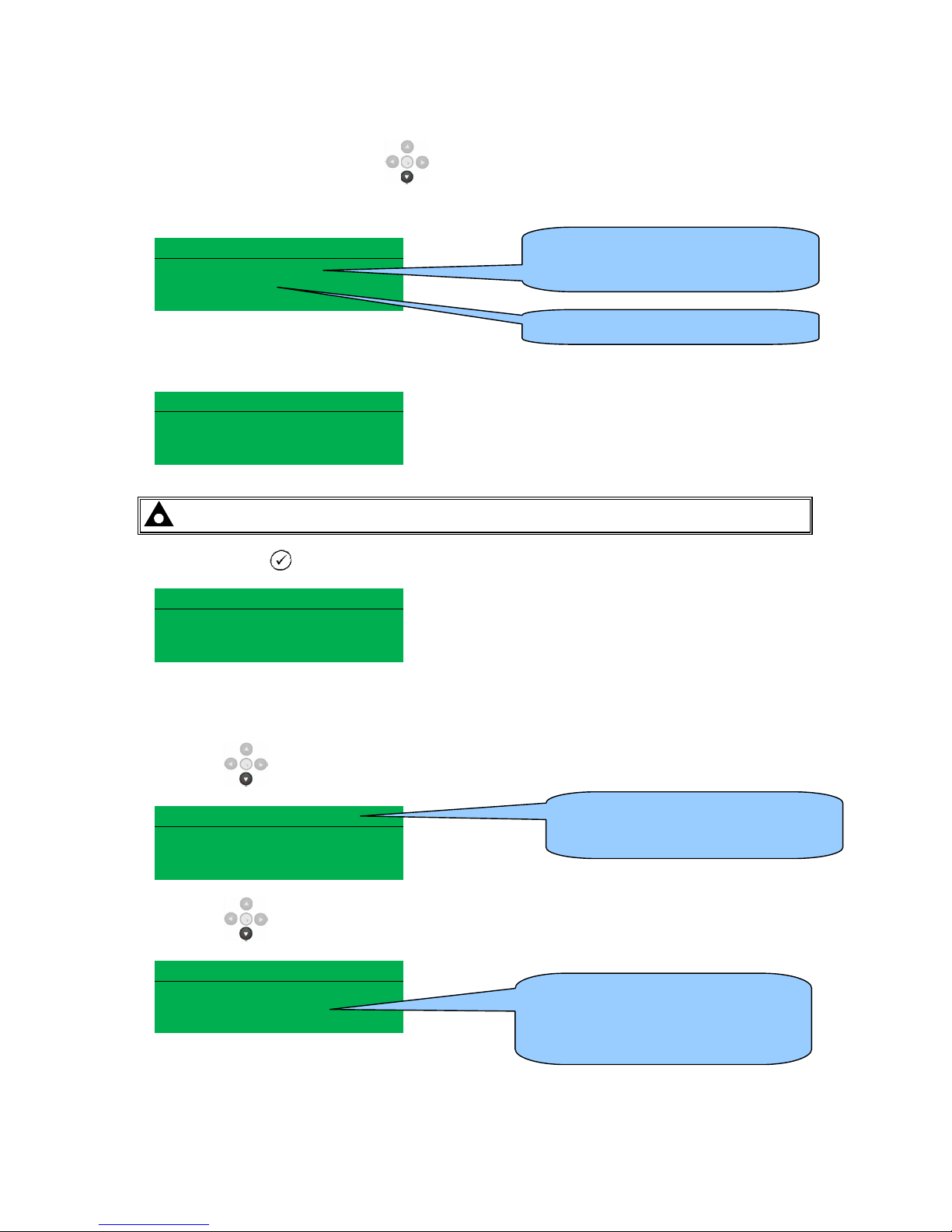
Viewing The Instrument Pages
71
5.4.8.2 DATA LOGGING PAGES
Whilst in the ‘ABOUT’ section, press to access more information about the data logging
settings.
Data Logging
Log to internal memory
Logging active
No USB drive present
Inserting a USB drive to the host USB will display the following change to the page.
Data Logging
Log to USB drive
Logging active
Do not remove USB drive
NOTE:- Removal of the USB drive should only be carried out using the following method.
Press and hold the
tick button until “Ok to remove USB drive” is displayed.
Data Logging
Log to USB drive
Logging active
Ok to remove USB drive
It is now safe to remove the USB drive.
This ensures the logging data file will save to memory complete and will not become corrupt.
Press down
to view the next page.
Data Logging
Time remaining
xxxx h xx m
Press down
to view the next page.
Data Logging
Memory remaining
xxxx
.
Location of stored data.
Internal module memory or external
USB memory.
If data logging is active or inactive
Remaining time available for logging
information.
xxxx hours xx minutes
Memory space remaining, this
depends what size memory drive is
fitted (Max 16Gb) or allocated internal
(2Mb) memory left available.
Page 72
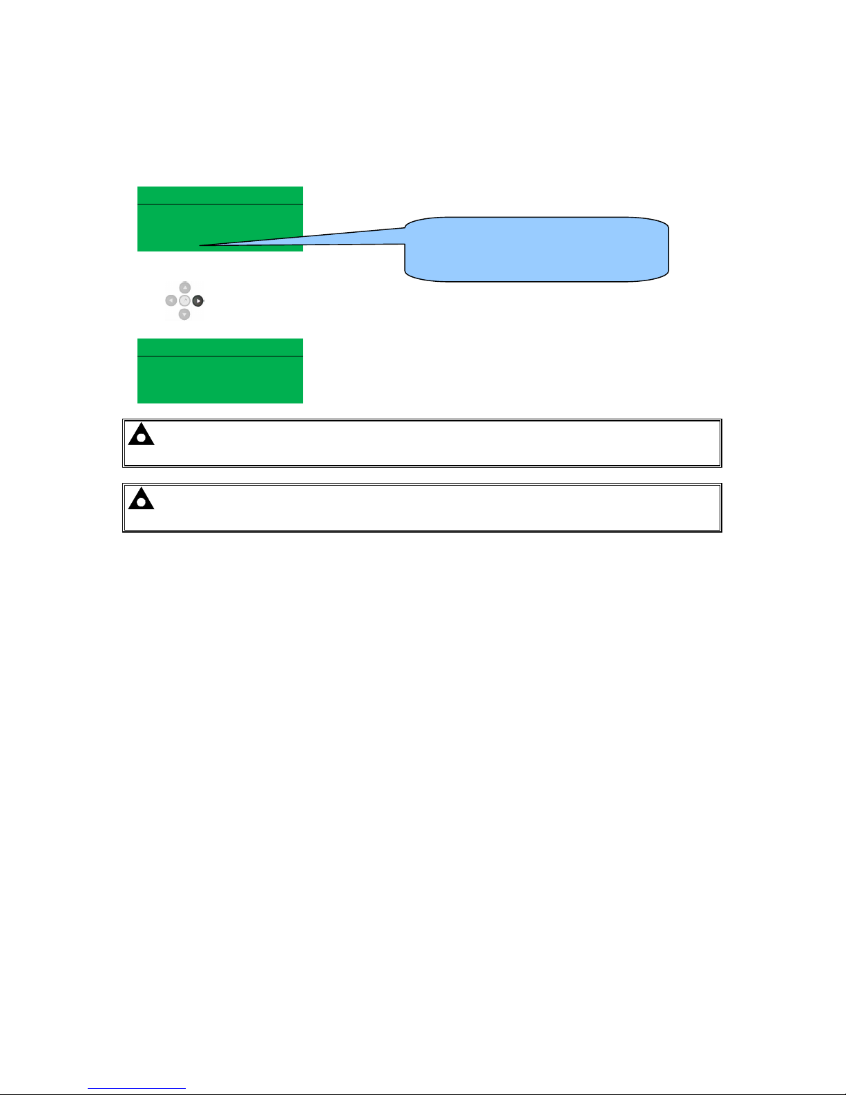
Viewing The Instrument Pages
72
5.4.9 CAN ERROR MESSAGES
When connected to a suitable CAN engine the controller displays alarm status messages from the
ECU.
Alarm
ECU Warning
Warning
Press to access the list of current active Engine DTCs (Diagnostic Trouble Codes).
Engine DTCs
The code interpreted by the module shows on the display as a text message.
Additionally, the manufacturer’s code is shown.
Water Level
Low
Xxx,xxx,xxx
NOTE: - For details on these code meanings, refer to the ECU instructions provided by
the engine manufacturer, or contact the engine manufacturer for further assistance.
NOTE: - For further details on connection to electronic engines please refer to Electronic
engines and DSE wiring. Part No. 057-004
Type of alarm that is triggered in the
DSE module (i.e. Warning or
Shutdown)
Page 73
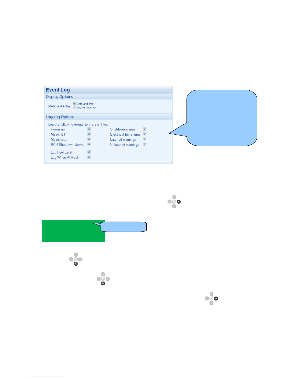
Viewing The Instrument Pages
73
5.5 VIEWING THE EVENT LOG
The module maintains a log of past alarms and/or selected status changes.
The log size has been increased in the module over past module updates and is always subject to
change. At the time of writing, the modules log is capable of storing the last 250 log entries.
Under default factory settings, the event log only includes shutdown and electrical trip alarms
logged (The event log does not contain Warning alarms); however, this is configurable by the
system designer using the DSE Configuration Suite software.
Once the log is full, any subsequent shutdown alarms will overwrite the oldest entry in the log.
Hence, the log will always contain the most recent shutdown alarms.
The module logs the alarm, along with the date and time of the event (or engine running hours if
configured to do so).
If the module is configured and connected to send SMS text
To view the event log, repeatedly press the next page button until the LCD screen displays the
Event log :
Event log 1
Oil Pressure Low
Shutdown
12 Sep 2007, 08:25:46
Press down
to view the next most recent shutdown alarm:
Continuing to press down
cycles through the past alarms after which the display shows the
most recent alarm and the cycle begins again.
To exit the event log and return to viewing the instruments, press the next page button to
select the next instrumentation page.
Example showing the
possible configuration of the
modules event log (DSE
Configuration Suite
Software)
This also shows the factory
settings of the module (Only
shutdown alarms and the
mains status are logged).
This is event 1.
Page 74
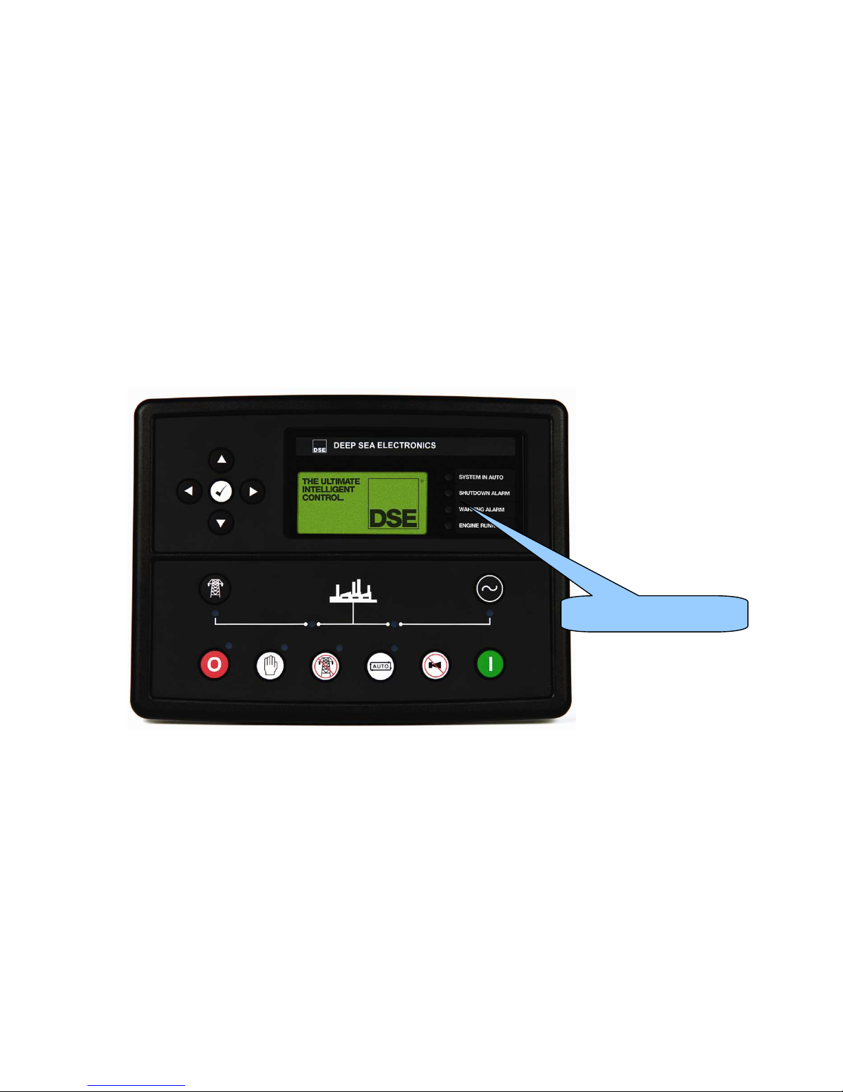
Control and Indications
74
5.6 USER CONFIGURABLE INDICATORS
These LEDs can be configured by the user to indicate any one of 100+
different functions based around the following:-
• Indications - Monitoring of a digital input and indicating associated
functioning user’s equipment - Such as Battery Charger On or Louvres
Open, etc.
• WARNINGS, ELECTRICAL TRIPS & SHUTDOWNS - Specific
indication of a particular warning or shutdown condition, backed up by
LCD indication - Such as Low Oil Pressure Shutdown, Low Coolant
level, etc.
• Status Indications - Indication of specific functions or sequences
derived from the modules operating state - Such as Safety On, Pre-
heating, Panel Locked, Generator Available, etc.
User configurable LEDs
Page 75
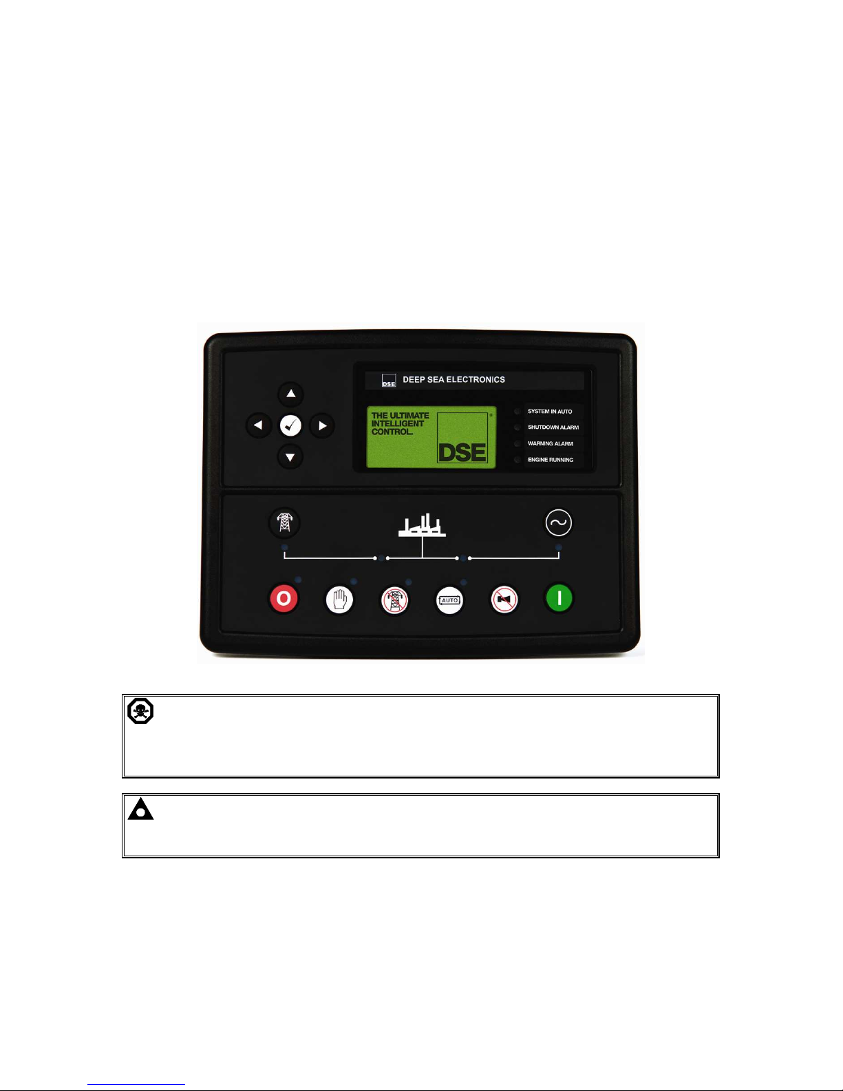
Operation
75
6 OPERATION
6.1 CONTROL
Control of the module is via push buttons mounted on the front of the module with STOP/RESET,
MANUAL, TEST, AUTO, ALARM MUTE and START functions. For normal operation, these are the
only controls which need to be operated. The smaller push buttons are used to access further
information such as mains voltage or to change the state of the load switching dev ices when in
manual mode. Details of their operation are provided later in this document.
The following descriptions detail the sequences followed by a module containing the standard ‘factory
configuration’. Always refer to your configuration source for the exact sequences and timers observed
by any particular module in the field.
CAUTION: - The module may instruct an engine start event due to external influences.
Therefore, it is possible for the engine to start at any time without warning. Prior to
performing any maintenance on the system, it is recommended that steps are taken to remove
the battery and isolate supplies.
NOTE: - This control module has PLC functionality built in. This can have change the
standard operation when used. (Default configuration the no PLC is set. See software manual
for more information)
Page 76
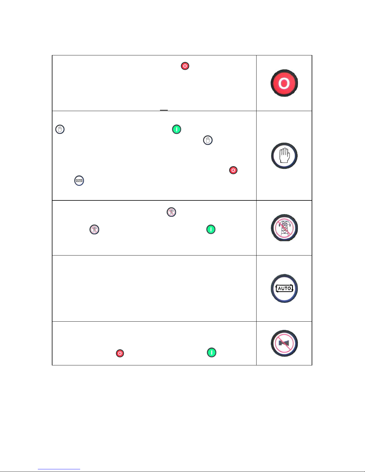
Operation
76
6.2 CONTROL PUSH-BUTTONS
Stop / Reset
This button places the module into its Stop/Reset
mode. This will clear any
alarm conditions for which the triggering criteria have been removed. If the
engine is running and the module is in Stop mode, the module will
automatically instruct the changeover device to unload the generator (‘Close
Generator’ becomes inactive (if used)). The fuel supply de-energises and the
engine comes to a standstill. Should a remote start signal be present while
operating in this mode, a remote start will not occur.
Manual
This mode allows manual control of the generator functions. Once in Manual
mode the module will respond to the start button, start the engine, and
run off load. If the engine is running off-load in the Manual
mode and a
remote start signal becomes present, the module will automatically instruct
the changeover device to place the generator on load (‘Close Generator’
becomes active (if used)). Upon removal of the remote start signal, the
generator remains on load until either selection of the ‘STOP/RESET ’ or
‘AUTO ’ modes.
For further details, please see the more detailed description of ‘Manual
operation’ elsewhere in this manual.
Test (DSE7420 only)
This button places the module into its ‘Test’ mode. This allows an on load
test of the generator.
Once in Test
mode the module will respond to the start button, start
the engine, and run on load.
For further details, please see the more detailed description of ‘Test operation’
elsewhere in this manual.
Auto
This button places the module into its ‘Automatic’ mode. This mode allows the
module to control the function of the generator automatically. The module will
monitor the remote start input and mains supply status and once a start request
is made, the set will be automatically started and placed on load.
Upon removal of the starting signal, the module will automatically transfer the
load from the generator and shut the set down observing the stop delay timer
and cooling timer as necessary. The module will then await the next start
event. For further details, please see the more detailed description of ‘Auto
operation’ elsewhere in this manual.
Mute / Lamp Test
This button silences the audible alarm if it is sounding and illuminates all of the
LEDs as a lamp test feature/
When correctly configured and fitted to a compatible engine ECU, pressing this
button in STOP/RESET mode after pressing the START button (to
power the ECU) will cancel any “passive” alarms on the engine ECU.
Page 77
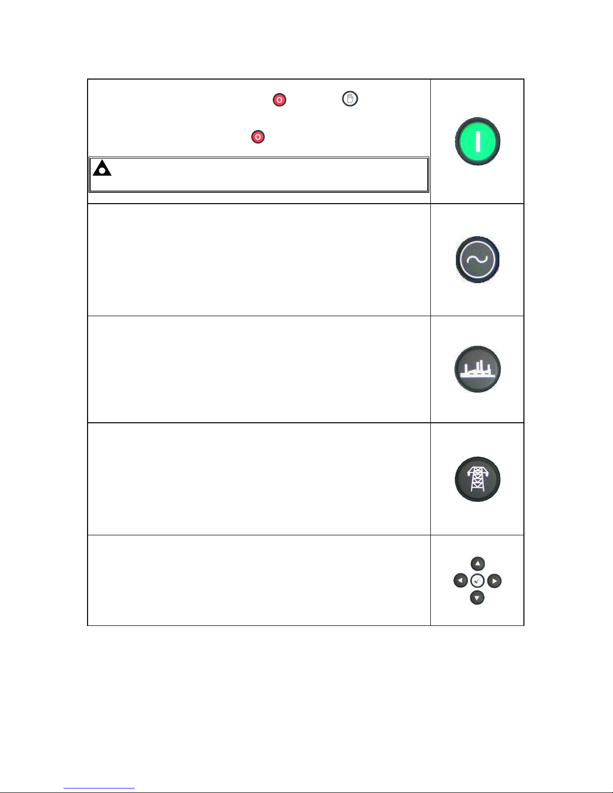
Operation
77
Start
This button is only active in STOP/RESET
or MANUAL mode.
Pressing this button in manual or test mode will start the engine and run off
load (manual) or on load (test).
Pressing this button in STOP/RESET
mode will turn on the CAN engine
ECU (when correctly configured and fitted to a compatible engine ECU)
NOTE:- Different modes of operation are possible - Please refer to
your configuration source for details.
Transfer to generator
Operative in Manual Mode only
‘Normal’ breaker button control
• Allows the operator to transfer the load to the generator
‘Alternative’ breaker button control
• If mains is on load, transfers the load to the generator.
• If generator is on load, opens the generator breaker
• If generator and mains are off load, closes the generator breaker.
Open generator (DSE7410 only)
Allows the operator to open the generator (when in Manual mode only)
Transfer to mains (DSE7420 only)
Operative in Manual Mode only
‘Normal’ breaker button control
• Allows the operator to transfer the load to the mains
‘Alternative’ breaker button control
• If generator is on load, transfers the load to the mains.
• If mains is on load, opens the mains breaker
• If generator and mains are off load, closes the mains breaker.
Menu navigation
Used for navigating the instrumentation, event log and configuration screens.
For further details, please see the more detailed description of these items
elsewhere in this manual.
6.3 ALTERNATIVE CONFIGURATIONS
Depending upon the configuration of your system by the generator supplier, the system may have
selectable configurations (for example to select between 50Hz and 60Hz running). If this has been
enabled your generator supplier will advise how this selection can be made (usually by externally
operated selector switch or by selecting the required configuration file in the module front panel
configuration editor).
Page 78

Operation
78
6.4 DUMMY LOAD / LOAD SHEDDING CONTROL
This feature may be enabled by the system designer to ensure the loading on the generator is kept to
a nominal amount. If the load is low, ‘dummy loads’ (typically static load banks) can be introduced to
ensure the engine is not too lightly loaded. Conversely as the load increases towards the maximum
rating of the set, non-essential loads can be shed to prevent overload of the generator.
6.2.1 DUMMY LOAD CONTROL
The dummy load control feature (if enabled) allows for a maximum of five dummy load steps.
When the set is first started, all configured Dummy Load Control outputs are de-energised.
Once the generator is placed onto load, the generator loading is monitored by the Dummy Load
Control scheme.
If the generator loading falls below the Dummy Load Control Trip setting (kW), the Dummy Load
Control Trip Delay is displayed on the module display. If the generator loading remains at this low
level for the duration of the timer, the first Dummy Load Control output is energised. This is used to
energise external circuits to switch in (for instance) a static load bank.
The generator loading has now been increased by the first dummy load. Again the generator loading
is monitored. This continues until all configured Dummy Load Control outputs are energised.
Should the generator loading rise above the Dummy Load Return level, the Dummy Load Return
Delay begins. If the loading remains at these levels after the completion of the timer, the ‘highest’
active Dummy Load Control output is de-energised. This continues until all Dummy Load Control
outputs have been de-energised.
6.2.2 LOAD SHEDDING CONTROL
The Load Shedding Control feature (if enabled) allows for a maximum of five load shedding steps.
When the generator is about to take load, the configured number of Load Shedding Control Outputs
at Startup will energise. This configurable setting allows (for instance) certain loads to be removed
from the generator prior to the set’s load switch being closed. This can be used to ensure the initial
loading of the set is kept to a minimum, below the Load Acceptance specification of the generating
set.
The generator is then placed on load. The Load Shedding Control scheme begins.
When the load reaches the Load Shedding Trip level the Trip Delay timer will start. If the generator
loading is still high when the timer expires, the first Load shedding Control output will energise. W hen
the load has been above the trip level for the duration of the timer the ‘next’ Load shedding Control
output will energise and so on until all Load Shedding Control outputs are energised.
If at any time the load falls back below the Load Shedding Return level, the Return Time will start. If
the load remains below the return level when the timer has expired the ‘highest’ Load Shedding
Control output that has been energised will be de-energised. This process will continue until all
outputs have been de-energised.
When the set enters a stopping sequence for any reason the Load Shedding control’ outputs will deenergise at the same time as the generator load switch is signalled to open.
NOTE:- Refer to DSE7400 Series Configuration Suite Manual (DSE part 057-160) for further
details on configuration.
Page 79
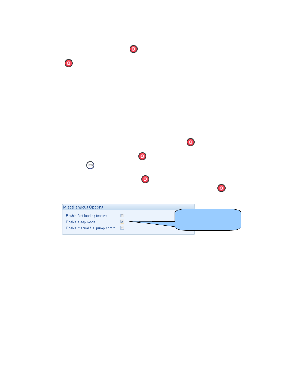
Operation
79
6.5 STOP MODE
STOP mode is activated by pressing the button.
In STOP
mode, the module will remove the generator from load (if necessary) before stopping
the engine if it is already running.
If the engine does not stop when requested, the FAIL TO STOP alarm is activated (subject to the
setting of the Fail to Stop timer). To detect the engine at rest the following must occur :
• Engine speed is zero as detected by the Magnetic Pickup or CANbus ECU (depending upon
module variant).
• Generator frequency must be zero.
• Oil pressure switch must be closed to indicate low oil pressure (MPU version only)
When the engine has stopped, it is possible to send configuration files to the module from DSE
Configuration Suite PC software and to enter the Front Panel Editor to change parameters.
Any latched alarms that have been cleared will be reset when STOP
mode is entered.
The engine will not be started when in STOP
mode. If remote start signals are given, the input is
ignored until AUTO mode is entered.
When configured to do so, When left in STOP
mode for five minutes with no presses of the
fascia buttons, the module enters low power mode. To ‘wake’ the module, press the button or any
other fascia control button.
Sleep mode configuration
in the DSE Configuration
Suite Software
Page 80
Operation
80
6.5.1 ECU OVERRIDE
NOTE:- ECU Override function is only applicable when the controller is configured for a
CAN engine.
NOTE:- Depending upon system design, the ECU may be powered or unpowered when
the module is in STOP mode. ECU override is only applicable if the ECU is unpowered when
in STOP mode.
When the ECU powered down (as is normal when in STOP mode), it is not possible to read the
diagnostic trouble codes or instrumentation. Additionally, it is not possible to use the engine
manufacturers’ configuration tools.
As the ECU is usually unpowered when the engine is not running, it must be turned on manually as
follows :
• Select STOP
mode on the DSE controller.
• Press and hold the START button to power the ECU. As the controller is in STOP mode,
the engine will not be started.
.
• The ECU will remain powered 2 minutes after the START button is released.
This is also useful if the engine manufacturer’s tools need to be connected to the engine, for instance
to configure the engine as the ECU needs to be powered up to perform this operation.
Page 81
Operation
81
6.6 MANUAL MODE
NOTE:- If a digital input configured to panel lock is active, changing module modes will
not be possible. Viewing the instruments and event logs is NOT affected by panel lock.
Activate Manual mode be pressing the pushbutton. An LED indicator beside the button confirms
this action.
Manual mode allows the operator to start and stop the set manually, and if required change the state
of the load switching devices.
6.6.1 WAITING IN MANUAL MODE
When in manual mode, the set will not start automatically.
To begin the starting sequence, press the
button.
6.6.2 STARTING SEQUENCE
NOTE:- There is no start delay in this mode of operation.
The fuel relay is energised and the engine is cranked.
NOTE:- If the unit has been configured for CAN, compatible ECU’s will receive the start
command via CAN.
If the engine fails to fire during this cranking attempt then the starter motor is disengaged for the
crank rest duration after which the next start attempt is made. Should this sequence continue beyond
the set number of attempts, the start sequence will be terminated and the display shows Fail to Start.
When the engine fires, the starter motor is disengaged. Speed detection is factory configured to be
derived from the main alternator output frequency but can additionally be measured from a Magnetic
Pickup mounted on the flywheel (Selected by the configuration software).
Additionally, rising oil pressure can be used disconnect the starter motor (but cannot detect
underspeed or overspeed).
NOTE:- If the unit has been configured for CAN, speed sensing is via CAN.
After the starter motor has disengaged, the Safety On timer activates, allowing Oil Pressure, High
Engine Temperature, Under-speed, Charge Fail and any delayed Auxiliary fault inputs to stabilise
without triggering the f ault.
Page 82
Operation
82
6.6.3 ENGINE RUNNING
In manual mode, the load is not transferred to the generator unless a ‘loading request’ is made.
A loading request can come from a number of sources.
• Pressing the transfer to generator
button
• Mains supply out of limits (DSE7420 only)
• Activation of an auxiliary input that has been configured to remote start on load
• Activation of the inbuilt exercise scheduler if configured for ‘on load’ runs.
NOTE:-The load transfer signal remains inactive until the Oil Pressure has risen. This
prevents excessive wear on the engine.
Once the load has been transferred to the generator, it will not be automatically transferred back to
the mains supply. To manually transfer the load back to the mains either:
• Press the Transfer to Mains
button (DSE7420 only)
• Press the Open Generator button (DSE7410 only)
• Press the Auto Mode
button to return to automatic mode.
For further details of breaker control, see the section entitled “controls and indications” elsewhere in
this manual.
6.6.4 MANUAL FUEL PUMP CONTROL
• Navigate to the instruments page using the buttons and locate FUEL LEVEL. is
shown on the module display to indicate that this feature is available.
• Press and hold the
button to energise the transfer pump. The pump starts two seconds
after the button is pressed.
• Release the
button to de-energise the transfer pump.
6.6.5 MANUAL SPEED CONTROL
• Navigate to the instruments page using the buttons and locate ENGINE SPEED. is
shown on the module display to indicate that this feature is available.
• Press the
button to enter edit mode
• Press
(up or down) to change the engine speed.
• Press the
button again to exit the editor and leave the engine running at the newly
selected speed.
Page 83
Operation
83
6.6.6 STOPPING SEQUENCE
In manual mode the set will continue to run until either :
• The stop button
is pressed – The set will immediately stop
• The auto button
is pressed. The set will observe all auto mode start requests and
stopping timers before beginning the Auto mode stopping sequence.
6.7 TEST MODE
NOTE:- Test Mode is only applicable to DSE7420 controller.
NOTE:- If a digital input configured to panel lock is active, changing module modes will
not be possible. Viewing the instruments and event logs is NOT affected by panel lock.
Activate test mode be pressing the pushbutton. An LED indicator beside the button confirms this
action.
Test mode will start the set and transfer the load to the generator to provide a Test on load function.
6.7.1 WAITING IN TEST MODE
When in test mode, the set will not start automatically.
To begin the starting sequence, press the
button.
6.7.2 STARTING SEQUENCE
The set begins to crank.
NOTE:- If the unit has been configured for CAN, compatible ECU’s will receive the start
command via CAN.
If the engine fails to fire during this cranking attempt then the starter motor is disengaged for the
crank rest duration after which the next start attempt is made. Should this sequence continue beyond
the set number of attempts, the start sequence will be terminated and the display shows Fail to Start.
When the engine fires, the starter motor is disengaged. Speed detection is factory configured to be
derived from the main alternator output frequency but can additionally be measured from a Magnetic
Pickup mounted on the flywheel (Selected by PC using the configuration software).
Additionally, rising oil pressure can be used disconnect the starter motor (but cannot detect
underspeed or overspeed).
NOTE:- If the unit has been configured for CAN, speed sensing is via CAN.
After the starter motor has disengaged, the Safety On timer activates, allowing Oil Pressure, High
Engine Temperature, Under-speed, Charge Fail and any delayed Auxiliary fault inputs to stabilise
without triggering the f ault.
Page 84
Operation
84
6.7.3 ENGINE RUNNING
Once the engine is running, the Warm Up timer, if selected, begins, allowing the engine to stabilise
before accepting the load.
Load will be automatically transferred from the mains supply to the generator.
NOTE:-The load transfer signal remains inactive until the Oil Pressure has risen. This
prevents excessive wear on the engine.
In test mode, the set will continue to run on load until either:
• The stop button
is pressed – The set will immediately stop
• The auto button
is pressed. The set will observe all auto mode start requests and
stopping timers before beginning the Auto mode stopping sequence.
Page 85
Operation
85
6.8 AUTOMATIC MODE
NOTE:- If a digital input configured to panel lock is active, changing module modes will
not be possible. Viewing the instruments and event logs is NOT affected by panel lock.
Activate auto mode be pressing the pushbutton. An LED indicator beside the button confirms this
action.
Auto mode will allow the generator to operate fully automatically, starting and stopping as required
with no user interv ention.
6.8.1 WAITING IN AUTO MODE
If a starting request is made, the starting sequence will begin.
Starting requests can be from the following sources:
• Mains supply out of limits (DSE7420 only)
• Activation of an auxiliary input that has been configured to remote start on load or remote
start off load.
• Activation of the inbuilt exercise scheduler.
• Instruction from external remote telemetry devices using the RS232 or RS485 interface
6.8.2 STARTING SEQUENCE
To allow for ‘false’ start requests such as mains brownouts, the start delay timer begins. There are
individual start delay timers for each of the different start request types.
Should all start requests be removed during the start delay timer, the unit will return to a stand-by
state.
If a start request is still present at the end of the start delay timer, the fuel relay is energised and the
engine will be cranked.
NOTE:- If the unit has been configured for CAN, compatible ECU’s will receive the start
command via CAN.
If the engine fails to fire during this cranking attempt then the starter motor is disengaged for the
crank rest duration after which the next start attempt begins. Should this sequence continue beyond
the set number of attempts, the start sequence will be terminated and the display shows Fail to Start.
The starter motor is disengaged when the engine fires. Speed detection is factory configured to be
derived from the main alternator output frequency, but can additionally be measured from a Magnetic
Pickup mounted on the flywheel (Selected by PC using the configuration software).
Additionally, rising oil pressure can be used to disconnect the starter motor (but cannot detect
underspeed or overspeed).
NOTE:- If the unit has been configured for CAN, speed sensing is via CAN.
After the starter motor has disengaged, the Safety On timer activates, allowing Oil Pressure, High
Engine Temperature, Under-speed, Charge Fail and any delayed Auxiliary fault inputs to stabilise
without triggering the f ault.
Page 86
Operation
86
6.8.3 ENGINE RUNNING
Once the engine is running, the Warm Up timer, if selected, begins, allowing the engine to stabilise
before accepting the load.
DSE7410 - The generator will be placed on load.
DSE7420 - Load will be transferred from the mains supply to the generator
NOTE:-The load transfer signal remains inactive until the Oil Pressure has risen. This
prevents excessive wear on the engine.
As the load increases and decreases, the module may (depending upon configuration) add dummy
loads or remove non-essential loads. This is configured as part of the Load Shedding and Dummy
Load control settings in the DSE Configuration Suite Software.
See section entitled Dummy Load / Load Shedding elsewhere in this document for further details.
If all start requests are removed, the stopping sequence will begin.
6.8.4 STOPPING SEQUENCE
The return delay timer operates to ensure that the starting request has been permanently removed
and isn’t just a short term removal. Should another start request be made during the cooling down
period, the set will return on load.
If there are no starting requests at the end of the return delay timer, the load is transferred back from
the generator to the mains supply and the cooling timer is initiated.
The cooling timer allows the set to run off load and cool sufficiently before being stopped. This is
particularly important where turbo chargers are fitted to the engine.
After the cooling timer has expired, the set is stopped.
Page 87
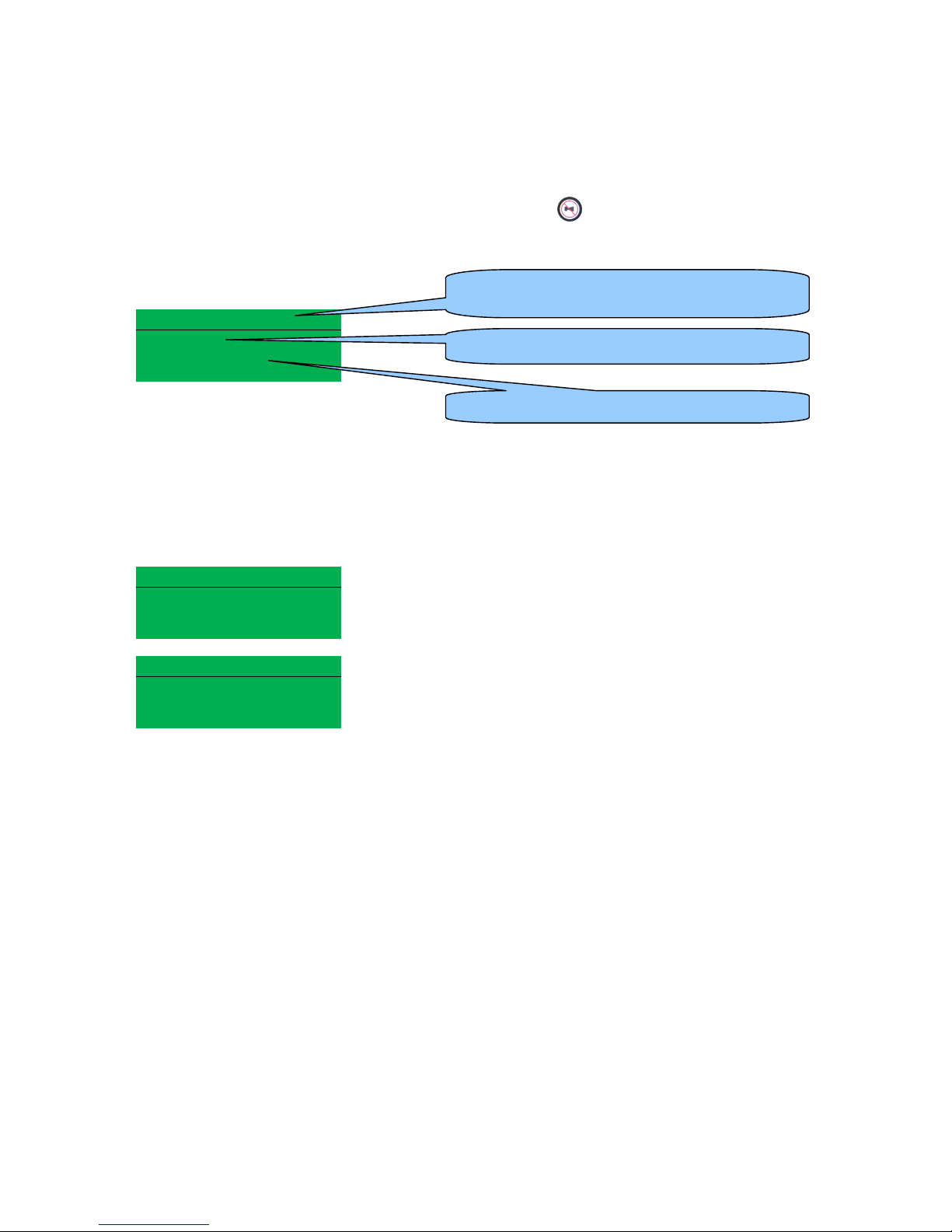
Protections
87
7 PROTECTIONS
When an alarm is present, the Audible Alarm will sound and the Common alarm LED if configured
will illuminate.
The audible alarm can be silenced by pressing the Mute button
The LCD display will jump from the ‘Information page’ to display the Alarm Page
Alarm 1/2
Warning
Low oil pressure
The LCD will display multiple alarms E.g. “High Engine Temperature shutdown”, “Emergency Stop”
and “Low Coolant Warning”. These will automatically scroll in the order that they occurred.
In the event of a warning alarm, the LCD will display the appropriate text. If a shutdown then occurs,
the module will again display the appropriate text.
Example:-
Alarm 1/2
Warning
Oil pressure Low
Alarm 2/2
Shutdown
Coolant Temperature High
The type of alarm. E.g. Shutdown or warning
The nature of alarm, e.g. Low oil pressure
Number of present alarms. This is alarm 1 of a
total of 2 present alarms
Page 88
Protections
88
7.1 PROTECTIONS DISABLED
User configuration is possible to prev ent Shutdown / Electrical Trip alarms from stopping the engine.
Under such conditions, Protections Disabled will appear on the m odule display to inform the operator
of this status.
This feature is provided to assist the system designer in meeting specifications for “Warning only”,
“Protections Disabled”, “Run to Destruction”, “War mode” or other similar wording.
When configuring this feature in the PC software, the system designer chooses to make the feature
either permanently active, or only active upon operation of an external switch. The system designer
provides this switch (not DSE) so its location will vary depending upon manufacturer, however it
normally takes the form of a key operated switch to prevent inadvertent activation. Depending upon
configuration, a warning alarm may be generated when the switch is operated.
The feature is configurable in the PC configuration software for the module. Writing a configuration to
the controller that has “Protections Disabled” configured, results in a warning message appearing on
the PC screen for the user to acknowledge before the controller’s configuration is changed. This
prevents inadvertent activation of the feature.
7.1.1 INDICATION / WARNING ALARMS
Under Indication or W arning alarms:
• The module operation is unaffected by the Protections Disabled feature. See sections entitled
Indications and Warnings elsewhere in this document.
7.1.2 SHUTDOWN / ELECTRICAL TRIP ALARMS
NOTE:- The EMERGENCY STOP input and shutdown alarm continues to operate even
when Protections Disabled has been activated.
Under Shutdown or Electrical Trip alarm conditions (excluding Emergency Stop):
• The alarm is displayed on the screen as detailed in the section entitled Shutdown alarms
elsewhere in this document.
• The set continues to run.
• The load switch maintains its current position (it is not opened if already closed)
• Shutdown Blocked also appears on the LCD screen to inform the operator that the
Protections Disabled feature has blocked the shutdown of the engine under the normally
critical fault.
• The ‘shutdown’ alarm is logged by the controllers Event Log (if configured to log shutdown
alarms) and logs that the Shutdown was prevented.
Page 89
Protections
89
7.1.3 CAN ALARMS
NOTE:- Please refer to the engine manufacturer’s documentation for ECU CAN error
message information.
CAN alarms are messages sent from the CAN ECU to the DSE controller and displayed as follows in
the below tables.
DM1 Signals. Messages from the CAN ECU that are configurable within the DSE module for:-
Warning, Electrical Trip, shutdown or None
Display Reason
Amber Warning
The CAN ECU has detected a Amber warning.
Red Shutdown
The CAN ECU has detected a Red Shutdown.
Malfunction
The CAN ECU has detected a Malfunction message.
Protect
The CAN ECU has detected a Protect message
Advanced CAN alarms Allows configuration of additional can messages from the engine ECU.
Display Reason
Water in Fuel
The ECU has detected water in the fuel action taken is set by settings in
advanced.
After T reatment
The ECU has detected “After Treatment alarm” consult engine
manufacturer for details” action taken by DSE controller is set by
settings in adv anced
NOTE:- For CAN ECU error code meanings, refer to the ECU documentation provided by
the engine manufacturer, or contact the engine manufacturer for further assistance.
Display Reason
CAN ECU WARNING
The engine ECU has detected a warning alarm and has informed the
DSE module of this situation. The exact error is also indicated on the
module’s display and action taken depending upon the setting for the
DM1 signals
ECU SHUTDOWN
The engine ECU has detected a shutdown alarm and has informed the
DSE module of this situation. The exact error is also indicated on the
module’s display.
ECU DATA FAIL
The module is configured for CAN operation and does not detect data on
the engine CAN datalink, the engine shuts down.
Page 90
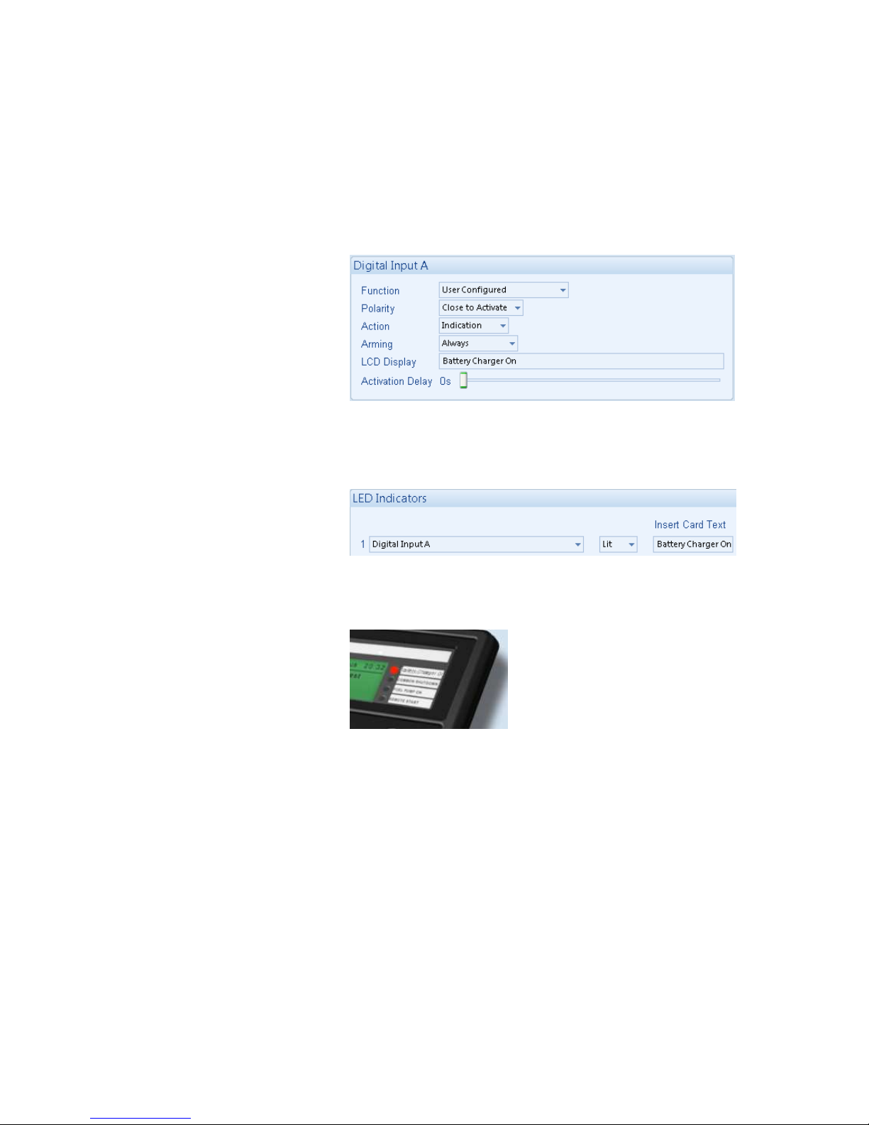
Protections
90
7.2 INDICATIONS
Indications are non-critical and often status conditions. They do not appear on the LCD of the module
as a text message. However, an output or LED indicator can be configured to draw the operator’s
attention to the event.
Example
• Input configured for
indication.
• The LCD text will not
appear on the module
display but can be added
in the configuration to
remind the system
designer what the input is
used for.
• As the input is configured
to Indication there is no
alarm generated.
• LED Indicator to make
LED1 illuminate when
Digital Input A is active.
• The Insert Card Text
allows the system
designer to print an insert
card detailing the LED
function.
• Sample showing
operation of the LED.
Page 91
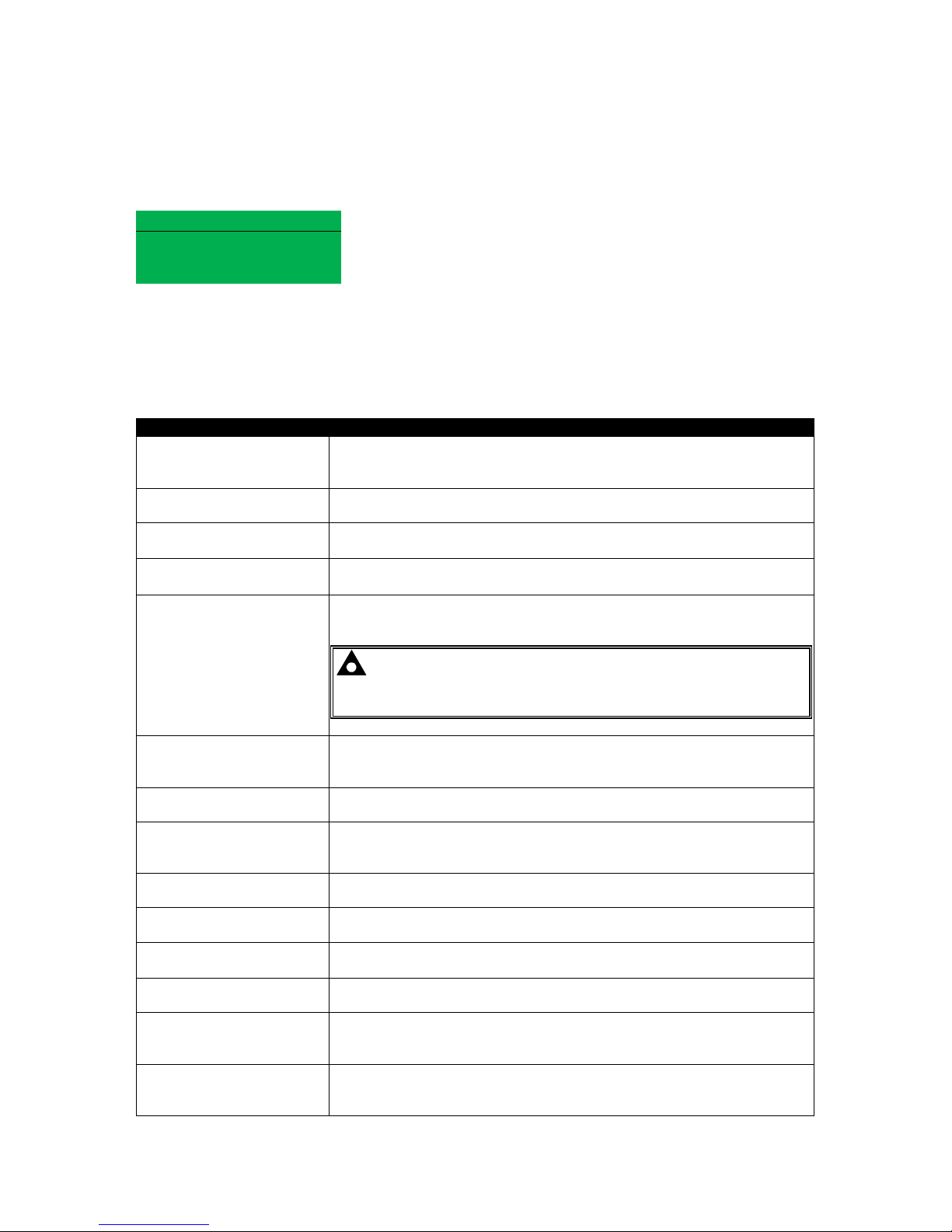
Protections
91
7.3 WARNINGS
Warnings are non-critical alarm conditions and do not affect the operation of the generator system,
they serve to draw the operators attention to an undesirable condition.
Example
Alarm 1/1
Charge Failure
Warning
In the event of an alarm the LCD will jump to the alarms page, and scroll through all active warnings
and shutdowns.
By default, warning alarms are self-resetting when the fault condition is removed. However enabling
‘all warnings are latched’ will cause warning alarms to latch until reset manually. This is enabled using
the DSE Configuration Suite in conjunction with a compatible PC.
Display Reason
AUXILIARY INPUTS
If an auxiliary input has been configured as a warning the appropriate
LCD message will be displayed and the COMMON ALARM LED will
illuminate.
CHARGE FAILURE
The auxiliary charge alternator voltage is low as measured from the
W/L terminal.
BATTERY UNDER
VOLTAGE
The DC supply has fallen below the low volts setting level for the
duration of the low battery volts timer
BATTERY OVER
VOLTAGE
The DC supply has risen above the high volts setting level for the
duration of the high battery volts timer
FAIL TO STOP
The module has detected a condition that indicates that the engine is
running when it has been instructed to stop.
NOTE:- ‘Fail to Stop’ could indicate a faulty oil pressure
sensor or switch - If the engine is at rest check oil sensor wiring
and configuration.
FUEL USAGE
Indicates the amount of fuel measured by the fuel level sensor is in
excess of the Fuel Usage alarm settings. This often indicates a fuel leak
or potential fuel theft.
LOW FUEL LEVEL
The level detected by the fuel level sensor is below the low f uel level
setting.
CAN ECU ERROR
The engine ECU has detected a warning alarm and has informed the
DSE module of this situation. The exact error is also indicated on the
module’s display.
kW OVERLOAD
The measured Total kW is above the setting of the kW overload
warning alarm
EARTH FAULT
The measured Earth Fault Current has been in excess of the earth fault
trip and has surpassed the IDMT curve of the Earth Fault alarm.
NEGATIVE PHASE
SEQUENCE
Indicates ‘out of balance’ current loading of the generator.
Sometimes also called Negative Sequence Current or Symmetry Fault
MAINTENANCE DUE
Indicates that the maintenance alarm has triggered. A visit is required
by the Generator service company.
LOADING VOLTAGE
NOT REACHED
Indicates that the generator voltage is not above the configured loading
voltage. The generator will not take load when the alarm is present after
the safety timer.
LOADING FREQUENCY
NOT REACHED
Indicates that the generator frequency is not above the configured
loading frequency. The generator will not take load when the alarm is
present after the safety timer.
Page 92

Protections
92
Display Reason
PROTECTIONS
DISABLED
Shutdown and electrical trip alarms can be disabled by user
configuration. In this case, Protections Disabled will appear on the
module display; The alarm text is displayed but the engine will continue
to run. This is ‘logged’ by the module to allow DSE Technical Staff to
check if the protections have been disabled on the module at any time.
LOW OIL PRESSURE
The module detects that the engine oil pressure has fallen below the
low oil pressure pre-alarm setting level after the Safety On timer has
expired.
ENGINE HIGH
TEMPERATURE
The module detects that the engine coolant temperature has exceeded
the high engine temperature pre-alarm setting level after the Safety On
timer has expired.
ENGINE LOW
TEMPERATURE
The module detects that the engine coolant temperature has fallen
below the high engine temperature pre-alarm setting level.
OVERSPEED
The engine speed has risen above the overspeed pre alarm setting
UNDERSPEED
The engine speed has fallen below the underspeed pre alarm setting
GENERATOR OVER
FREQUENCY
The generator output frequency has risen above the pre-set pre-alarm
setting.
GENERATOR UNDER
FREQUENCY
The generator output frequency has fallen below the pre-set pre-alarm
setting after the Safety On timer has expired.
GENERATOR OVER
VOLTAGE
The generator output voltage has risen above the pre-set pre-alarm
setting.
GENERATOR UNDER
VOLTAGE
The generator output voltage has fallen below the pre-set pre-alarm
setting after the Safety On timer has expired.
INSUFFICIENT
CAPACITY
f the generator reach full load when they are in parallel with the mains
(utility). The LCD will indicate ‘INSUFFICIENT CAPACITY’ and the
COMMON ALARM LED will illuminate.
MAINS FAILED TO
CLOSE
If the mains breaker fails to close, a warning is initiated. The LCD will
indicate ‘MAINS FAILED TO CLOSE’ and the COMMON ALARM LED
will illuminate.
MAINS FAILED TO OPEN
If the mains breaker fails to open, a warning is initiated. The LCD will
indicate ‘MAINS FAILED TO OPEN’ and the COMMON ALARM LED
will illuminate.
ECU WARNING
The engine ECU has detected a warning alarm and has informed the
DSE module of this situation. The exact error is also indicated on the
module’s display.
If the module is configured for, CAN and receives an “error” message from the engine control unit,
‘CAN ECU Warning” is shown on the module’s display and a warning alarm is generated.
7.4 HIGH CURRENT WARNING ALARM
GENERATOR HIGH CURRENT, if the module detects a generator output current in excess of the
pre-set trip a warning alarm initiates. The module shows Alarm W arning High Current. If this high
current condition continues for an excess period, then the alarm escalates to a shutdown condition.
For further details of the high current alarm, please see High Current Shutdown Alarm.
By default, High Current Warning Alarm is self-resetting when the overcurrent condition is removed.
However enabling ‘all warnings are latched’ will cause the alarm to latch until reset manually. This is
enabled using the DSE Configuration Suite in conjunction with a compatible PC.
Page 93
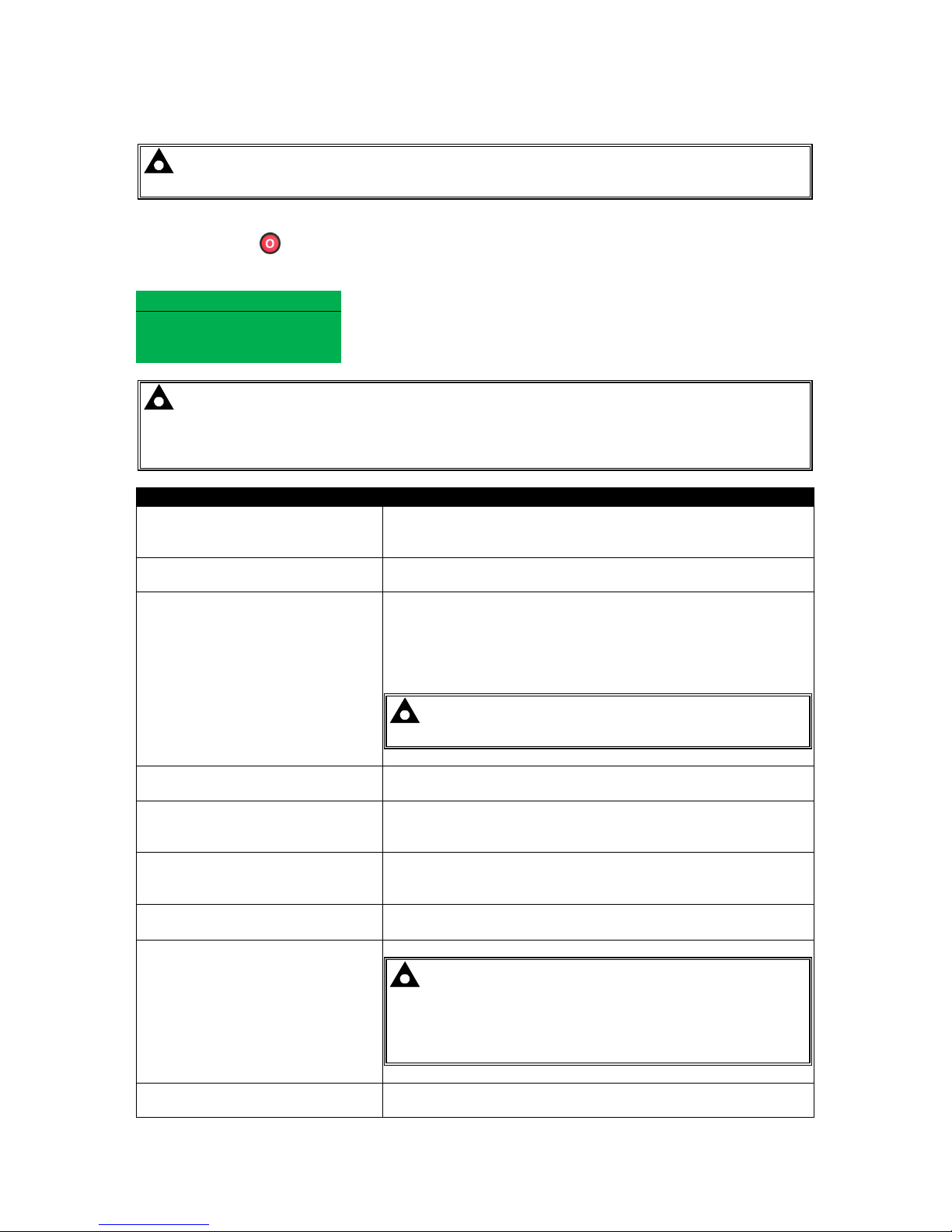
Protections
93
7.5 SHUTDOWNS
NOTE:- Shutdown and Electrical Trip alarms can be disabled by user configuration. See
the section entitled Protections Disabled elsewhere in this document.
Shutdowns are latching alarms and stop the Generator. Clear the alarm and remove the fault then
press Stop/Reset
to reset the module.
Example
Alarm 1/1
Oil Pressure Low
Shutdown
NOTE:- The alarm condition must be rectified before a reset will take place. If the alarm
condition remains, it will not be possible to reset the unit (The exception to this is the Low Oil
Pressure alarm and similar ‘active from safety on’ alarms, as the oil pressure will be low with
the engine at rest).
Display Reason
EARTH FAULT
The measured Earth Fault Current has been in excess of the
earth fault trip and has surpassed the IDMT curv e of the Earth
Fault alarm.
FAIL TO START
The engine has not fired after the preset number of start
attempts
EMERGENCY STOP
The emergency stop button has been depressed. This a failsafe
(normally closed to battery positive) input and will immediately
stop the set should the signal be removed.
Removal of the battery positive supply from the emergency
stop input will also remove DC supply from the Fuel and Start
outputs of the controller.
NOTE:- The Emergency Stop Positive signal must be
present otherwise the unit will shutdown.
LOW OIL PRESSURE
The engine oil pressure has fallen below the low oil pressure
trip setting level after the Safety On timer has expired.
ENGINE HIGH TEMPERATURE
The engine coolant temperature has exceeded the high engine
temperature trip setting level after the Safety On timer has
expired.
FUEL USAGE
Indicates the amount of fuel measured by the fuel level sensor
is in excess of the Fuel Usage alarm settings. This often
indicates a fuel leak or potential fuel theft.
PHASE ROTATION
The phase rotation is measured as being different to the
configured direction.
OVERSPEED
The engine speed has exceeded the pre-set trip
NOTE:-During the start-up sequence, the overspeed
trip logic can be configured to allow an extra trip level
margin. This is used to prevent nuisance tripping on startup - Refer to the DSE7400 series configuration software
manual under heading ‘Overspeed Overshoot’ for details.
UNDERSPEED
The engine speed has fallen below the pre-set trip after the
Safety On timer has expired.
Page 94

Protections
94
Display Reason
GENERATOR OVER
FREQUENCY
The generator output frequency has risen above the preset
level
GENERATOR UNDER
FREQUENCY
The generator output frequency has fallen below the preset
level
GENERATOR OVER VOLTAGE
The generator output voltage has risen above the preset level
GENERATOR UNDER VOLTAGE
The generator output voltage has fallen below the preset level
OIL PRESSURE SENSOR OPEN
CIRCUIT
The oil pressure sensor is detected as not being present (open
circuit)
AUXILIARY INPUTS
An active auxiliary input configured as a shutdown will cause
the engine to shut down. The display shows the text as
configured by the user.
LOSS OF SPEED SIGNAL
The speed signal from the magnetic pickup is not being
received by the DSE controller.
ECU DATA FAIL
The module is configured for CAN operation and does not
detect data on the engine Can datalink, the engine shuts down.
ECU SHUTDOWN
The engine ECU has detected a shutdown alarm and has
informed the DSE module of this situation. The exact error is
also indicated on the module’s display.
kW OVERLOAD
The measured Total kW is above the setting of the kW
overload shutdown alarm
NEGATIVE PHASE SEQUENCE
Indicates ‘out of balance’ current loading of the generator.
Sometimes also called Negative Sequence Current or
Symmetry Fault
MAINTENANCE DUE
Indicates that the maintenance alarm has triggered. A visit is
required by the Generator service company.
GENERATOR HIGH CURRENT
A High Current condition has continued for an excess period,
then the alarm escalates to either a shutdown or electrical trip
condition (depending upon module configuration). For further
details of the high current alarm, please see High Current
Shutdown / Electrical Trip Alarm.
LOADING VOLTAGE NOT
REACHED
Indicates that the generator voltage is not above the configured
loading voltage after the safety timer. The generator will
shutdown.
LOADING FREQUENCY NOT
REACHED
Indicates that the generator frequency is not above the
configured loading frequency after the safety timer. The
generator will shutdown.
PROTECTIONS DISABLED
Shutdown and electrical trip alarms can be disabled by user
configuration. In this case, Protections Disabled will appear on
the module display; The alarm text will be displayed but the
engine will continue to run. This is ‘logged’ by the module to
allow DSE Technical Staff to check if the protections have been
disabled on the module at any time.
Page 95
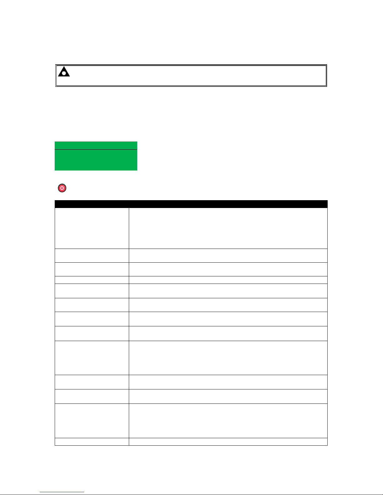
Protections
95
7.6 ELECTRICAL TRIPS
NOTE:- Shutdown and Electrical Trip alarms can be disabled by user configuration. See
the section entitled Protections Disabled elsewhere in this document.
Electrical trips are latching and stop the Generator but in a controlled manner. On initiation of the
electrical trip condition the module will de-energise the ‘Close Generator’ Output to remove the load
from the generator. Once this has occurred the module will start the Cooling timer and allow the
engine to cool off-load before shutting down the engine. The alarm must be accepted and cleared,
and the fault removed to reset the module.
Example
Alarm 1/1
Generator Current High
Electrical Trip
Electrical trips are latching alarms and stop the Generator. Remove the fault then press Stop/Reset
to reset the module.
Display Reason
GENERATOR HIGH
CURRENT
If a generator output in excess of the high current alarm point, a warning
alarm occurs. If this high current condition continues for an excess
period, then the alarm escalates to either a shutdown or electrical trip
condition (depending upon module configuration). For further details of
the high current alarm, please see High Current Shutdown / Electrical
Trip Alarm.
AUXILIARY INPUTS
If an auxiliary input configured as an electrical trip is active, the user
configured message shows on the display.
kW OVERLOAD
The measured Total kW is above the setting of the kW overload
Electrical Trip alarm
EARTH FAULT
The measured Earth Current is above the setting of the Earth fault alarm.
NEGATIVE PHASE
SEQUENCE
Indicates ‘out of balance’ current loading of the generator.
Sometimes also called Negative Sequence Current or Symmetry Fault
FUEL USAGE
Indicates the amount of fuel used is in excess of the Fuel Usage alarm
settings. This often indicates a fuel leak or potential fuel theft.
LOADING VOLTAGE
NOT REACHED
Indicates that the generator voltage is not above the configured loading
voltage after the safety timer. The generator will shutdown.
LOADING FREQUENCY
NOT REACHED
Indicates that the generator frequency is not above the configured
loading frequency after the safety timer. The generator will shutdown.
PROTECTIONS
DISABLED
Shutdown and electrical trip alarms is disabled by user configuration. In
this case, Protections Disabled will appear on the module display; The
alarm text is displayed but the engine will continue to run. This is ‘logged’
by the module to allow DSE Technical Staff to check if the protections
have been disabled on the module at any time.
GENERATOR UNDER
FREQUENCY
The generator output frequency has fallen below the preset level
GENERATOR UNDER
VOLTAGE
The generator output voltage has fallen below the preset level
INSUFFICIENT
CAPACITY
If the module is configured for Mains CT and the load levels are so high
that the generator is unable to supply enough load to maintain the
configured mains level, insufficient capacity will be displayed and the
COMMON ALARM LED will flash. The generator will provide 100% of its
capacity and the loading on the mains will increase.
UNDERSPEED
The engine speed has fallen below the underspeed setting
Page 96

Protections
96
7.7 HIGH CURRENT SHUTDOWN / ELECTRICAL TRIP ALARM
The overcurrent alarm combines a simple warning trip level with a fully functioning IDMT curve for
thermal protection.
7.7.1 IMMEDIATE WARNING
If the Immediate Warning is enabled, the controller generates a warning alarm as soon as the Trip
level is reached. The alarm automatically resets once the generator loading current falls below the
Trip level (unless All Warnings are latched is enabled). For further advice, consult your generator
supplier.
7.7.2 IDMT ALARM
If the IDMT Alarm is enabled, the controller begins following the IDMT ‘curve’ when the trip level is
passed.
If the Trip is surpassed for an excess amount of time the IDMT Alarm triggers (Shutdown or Electric
trip as selected in Action).
High current shutdown is a latching alarm and stops the Generator.
Remove the fault then press Stop/Reset
to reset the module.
High current electrical trip is a latching alarm and removes the generator from the load, before
stopping the Generator after the off load cooling timer.
Remove the fault then press Stop/Reset
to reset the module.
The higher the overload, the faster the trip. The speed of the trip is dependent upon the fixed formula:
T = t / ((IA / I T) – 1)
2
Where: T is the tripping time in seconds
I
A
is the actual current of the most highly loaded line (L1 or L2 or L3)
I
T
is the delayed over-current trip point
t is the time multiplier setting and also represents the tripping time in seconds at twice full load (when I
A
/ IT = 2).
Page 97
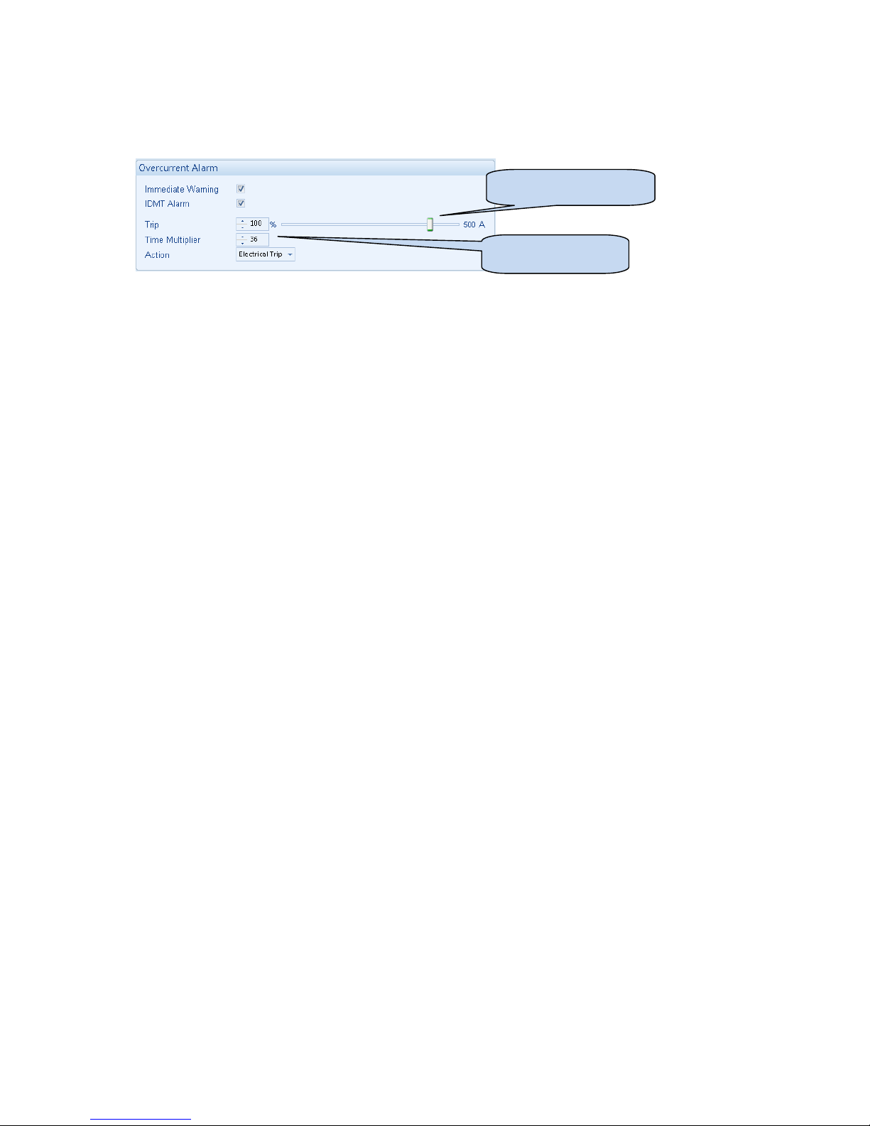
Protections
97
Factory settings for the IDMT Alarm when used on a brushless alternator are as follows (screen
capture from the DSE Configuration Suite PC software :
These settings provide for normal running of the generator up to 100% full load. If full load is
surpassed, the Immediate Warning alarm is triggered, the set continues to run.
The effect of an overload on the generator is that the alternator windings begin to overheat; the aim
of the IDMT alarm is to prevent the windings being overload (heated) too much. The amount of time
that the set can be safely overloaded is governed by how high the overload condition is.
With typical settings as above, the tripping curve is followed as shown below.
This allows for overload of the set to the limits of the Typical Brushless Alternator whereby 110%
overload is permitted for 1 hour.
If the set load reduces, the controller then follows a cooling curve. This means that a second overload
condition may trip much sooner than the first as the controller knows if the windings have not cooled
suff iciently.
For further details on the Thermal damage curve of your alternator, you are referred to your alternator
manufacturer and generator supplier.
I
T
(Trip setting value)
t
(time multiplier)
Page 98
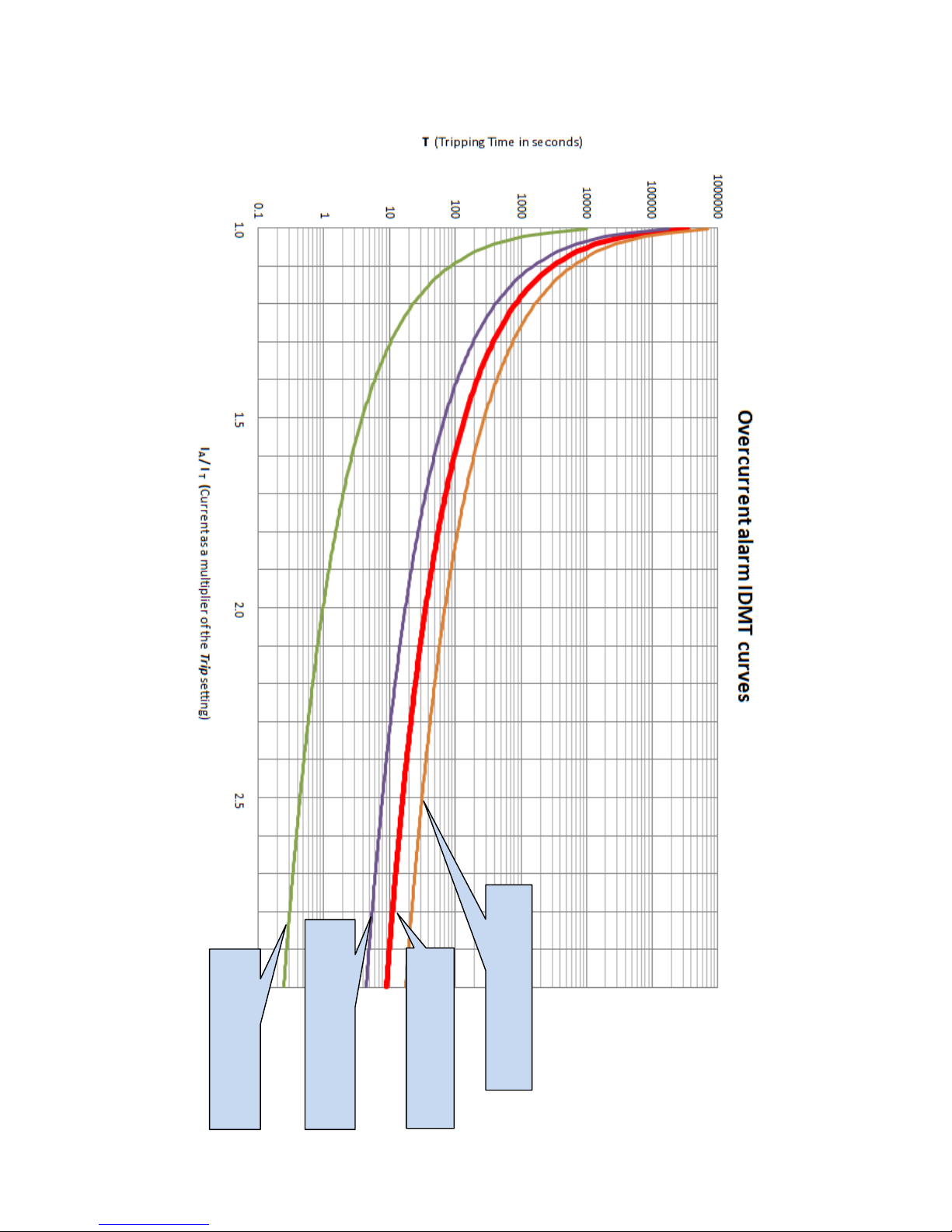
Protections
98
Factory setting
(Time Multiplier = 36
‘Fastest’ trip setting
(Time Multiplier = 1
Slower than Factory setting
(Time Multiplier = 72
Faster than Factory setting
(Time Multiplier = 18
Page 99
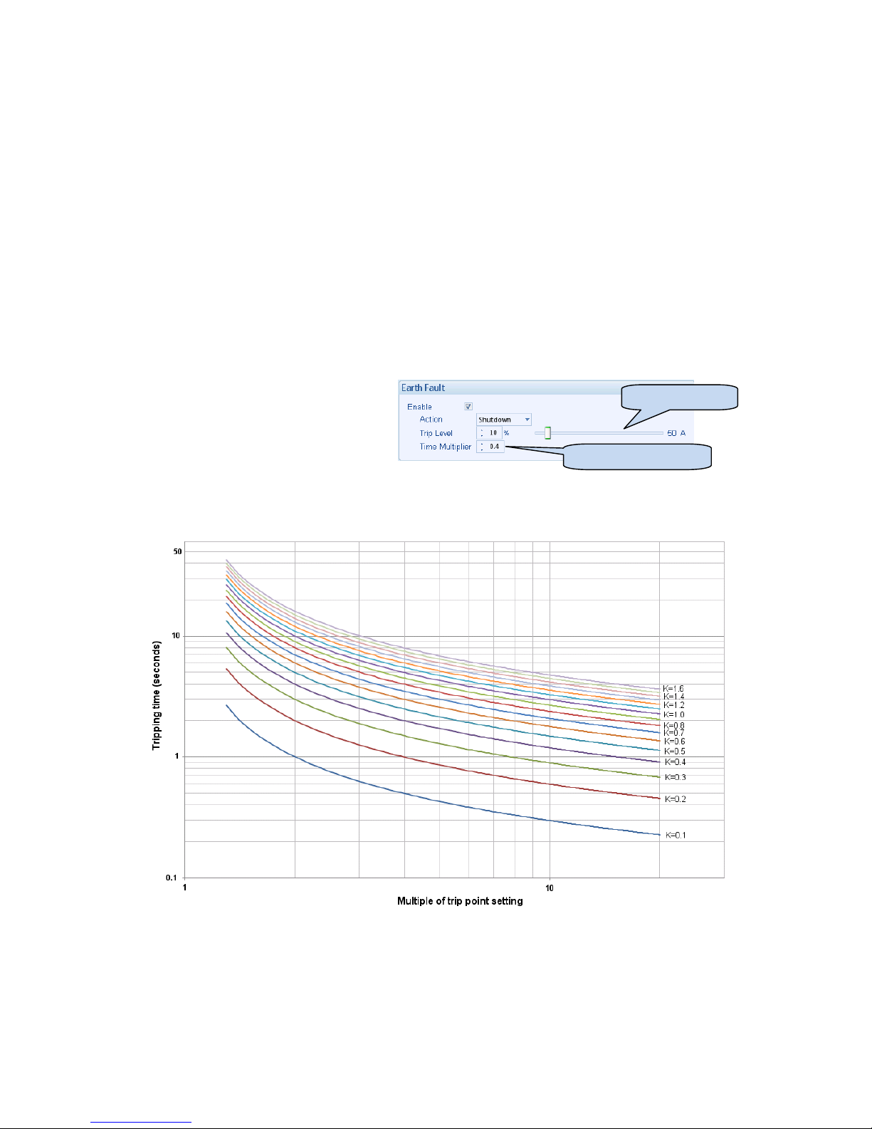
Protections
99
7.8 EARTH FAULT SHUTDOWN / ELECTRICAL TRIP ALARM
When the module is suitably connected using the ‘Earth Fault CT’. The module measures Earth Fault
and can optionally be configured to generate an alarm condition (shutdown or electrical trip) when a
specified lev el is surpassed.
If the Earth Fault alarm is enabled, the controller begins following the IDMT ‘curve’. If the Trip is
surpassed for an excess amount of time the Alarm triggers (Shutdown or Electric trip as selected in
Action).
The higher the Earth Fault, the faster the trip. The speed of the trip is dependent upon the fixed
formula :
T = K x 0.14 / ((I / Is)
0.02
-1)
Where: T is the tripping time in seconds (accurate to +/- 5% or +/- 50ms (whichever is the greater)
K is the time mu ltiplier setting
I is the actual earth current measured
Is is the trip setting value
The settings shown in the example above are a screen capture of the DSE factory settings, taken
from the DSE Configuration Suite software.
IS (Trip setting
K (time multiplier setting)
Page 100
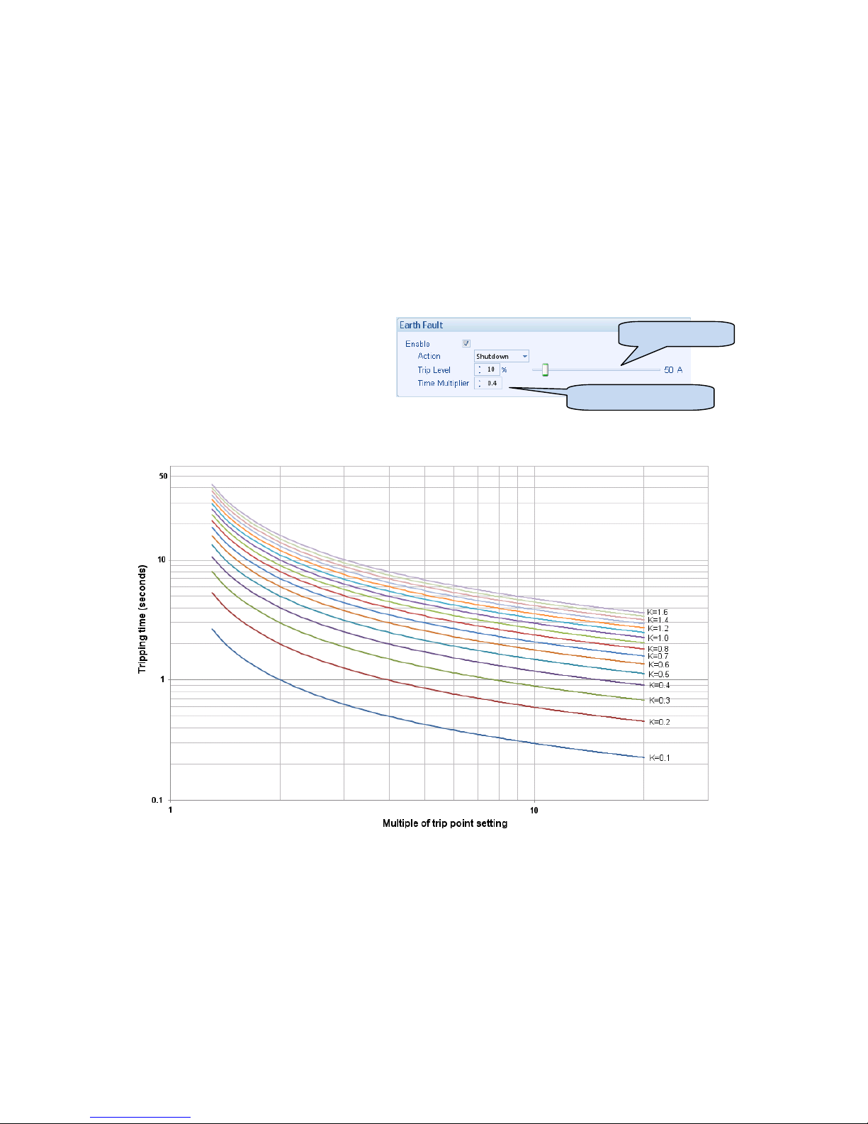
Protections
100
7.9 SHORT CIRCUIT ALARM
If the Short Circuit alarm is enabled, the controller begins following the IDMT ‘curve’. If the Trip is
surpassed for an excess amount of time the Alarm triggers (Shutdown or Electrical trip as selected in
Action).
The higher the Short Circuit, the faster the trip. The speed of the trip is dependent upon the fixed
formula :
T = K x 0.14 / ((I / Is)
0.02
-1)
Where: T is the tripping time in seconds (accurate to +/- 5% or +/- 50ms (whichever is the greater)
K is the time mu ltiplier setting
I is the actual current measured
Is is the trip setting value
The settings shown in the example above are a screen capture of the DSE factory settings, taken
from the DSE Configuration Suite software.
IS (Trip setting
K (time multiplier setting)
 Loading...