

DSE DSE7120 MKII, DSE7110 MKII Operator's Manual

DSE7110 MKII & DSE7120 MKII Operator Manual ISSUE 2
DEEP SEA ELECTRONICS PLC
DSE7110 MKII & DSE7120 MKII
Operator Manual
Document Number: 057-182
Author: Ashley Senior
DSE7110 MKII & DSE7120 MKII Operator Manual
2
DEEP SEA ELECTRONICS PLC
Highfield House
Hunmanby
North Yorkshire
YO14 0PH
ENGLAND
Sales Tel: +44 (0) 1723 890099
Sales Fax: +44 (0) 1723 893303
E-mail: sales@deepseaplc.com
Website: www.deepseaplc.com
DSE7110 MKII & DSE7120 MKII Operator Manual
© Deep Sea Electronics Plc
All rights reserved. No part of this publication may be reproduced in any material form (including
photocopying or storing in any medium by electronic means or other) without the written permission
of the copyright holder except in accordance with the provisions of the Copyright, Designs and
Patents Act 1988.
Applications for the copyright holder’s written permission to reproduce any part of this publication
should be addressed to Deep Sea Electronics Plc at the address above.
The DSE logo is a UK registered trademarks of Deep Sea Electronics PLC.
Any reference to trademarked product names used within this publication is owned by their
respective companies.
Deep Sea Electronics Plc reserves the right to change the contents of this document without prior
notice.
Amendments List
Issue Comments
Minimum Module
Version Required
1 Initial release V 1.0.0
2
Added changes to Front Panel Editor and new part number for installation
instructions
V1.1.58
Typeface: The typeface used in this document is Arial. Care should be taken not to mistake the upper case letter I with the numeral 1. The
numeral 1 has a top serif to avoid this confusion.
Clarification of notation used within this publication.
NOTE
Highlights an essential element of a procedure to ensure correctness.
CAUTION!
Indicates a procedure or practice, which, if not strictly observed, could
result in damage or destruction of equipment.
WARNING!
Indicates a procedure or practice, which could result in injury to
personnel or loss of life if not followed correctly.

DSE7110 MKII & DSE7120 MKII Operator Manual
3
TABLE OF CONTENTS
Section Page
1 BIBLIOGRAPHY .............................................................................................. 7
1.1 INSTALLATION INSTRUCTIONS .................................................................................. 7
1.2 TRAINING GUIDES ........................................................................................................ 7
1.3 MANUALS ...................................................................................................................... 7
1.4 THIRD PARTY DOCUMENTS ........................................................................................ 7
2 INTRODUCTION .............................................................................................. 8
3 SPECIFICATION .............................................................................................. 9
3.1 SHORT NAMES .............................................................................................................. 9
3.2 OPERATING TEMPERATURE ....................................................................................... 9
3.3 REQUIREMENTS FOR UL CERTIFICATION ................................................................. 9
3.4 TERMINAL SPECIFICATION ....................................................................................... 10
3.5 POWER SUPPLY REQUIREMENTS ............................................................................ 10
3.5.1 MODULE SUPPLY INSTRUMENTATION DISPLAY .............................................. 10
3.6 VOLTAGE & FREQUENCY SENSING ......................................................................... 11
3.7 CURRENT SENSING .................................................................................................... 11
3.7.1 VA RATING OF THE CTS ...................................................................................... 12
3.7.2 CT POLARITY........................................................................................................ 13
3.7.3 CT PHASING ......................................................................................................... 13
3.7.4 CT CLASS ............................................................................................................. 13
3.8 INPUTS......................................................................................................................... 14
3.8.1 DIGITAL INPUTS ................................................................................................... 14
3.8.2 ANALOGUE INPUTS ............................................................................................. 14
3.8.2.1 OIL PRESSURE .............................................................................................. 14
3.8.2.2 COOLANT TEMPERATURE ........................................................................... 14
3.8.2.3 FUEL LEVEL SENSOR ................................................................................... 15
3.8.2.4 FLEXIBLE SENSOR ........................................................................................ 15
3.8.3 CHARGE FAIL INPUT ............................................................................................ 15
3.8.4 MAGNETIC PICKUP .............................................................................................. 16
3.9 OUTPUTS..................................................................................................................... 16
3.9.1 DC OUTPUTS A & B (FUEL & START) .................................................................. 16
3.9.2 CONFIGURABLE VOLT-FREE OUTPUTS C & D .................................................. 16
3.9.3 CONFIGURABLE DC OUTPUTS E, F, G & H ........................................................ 16
3.10 COMMUNICATION PORTS ...................................................................................... 17
3.10.1 COMMUNICATION PORT USAGE ....................................................................... 17
3.10.1.1 CAN INTERFACE .......................................................................................... 17
3.10.1.2 USB CONNECTION ........................................................................................ 18
3.11 ADDING AN EXTERNAL SOUNDER ........................................................................ 19
3.12 ACCUMULATED INSTRUMENTATION .................................................................... 19
3.13 DIMENSIONS AND MOUNTING ............................................................................... 20
3.13.1 DIMENSIONS ........................................................................................................ 20
3.13.2 PANEL CUTOUT.................................................................................................... 20
3.13.3 WEIGHT ................................................................................................................ 20
3.13.4 FIXING CLIPS ........................................................................................................ 21
3.13.5 CABLE TIE FIXING POINTS .................................................................................. 22
3.13.6 SILICON SEALING GASKET ................................................................................. 22
3.13.7 APPLICABLE STANDARDS ................................................................................... 23
3.13.8 ENCLOSURE CLASSIFICATIONS ......................................................................... 25
3.13.8.1 IP CLASSIFICATIONS .................................................................................... 25
3.13.8.2 NEMA CLASSIFICATIONS ............................................................................. 26
4 INSTALLATION ............................................................................................. 27
4.1 TERMINAL DESCRIPTION .......................................................................................... 28
4.1.1 DC SUPPLY, E-STOP INPUT, DC OUTPUTS & CHARGE FAIL INPUT ................ 28

DSE7110 MKII & DSE7120 MKII Operator Manual
4
4.1.2 ANALOGUE SENSORS ......................................................................................... 29
4.1.3 MPU & CAN ........................................................................................................... 29
4.1.4 OUTPUT C & D & GENERATOR VOLTAGE & FREQUENCY SENSING ............... 30
4.1.5 MAINS VOLTAGE & FREQUENCY SENSING (7120 MKII ONLY) ......................... 30
4.1.6 CURRENT TRANSFORMERS ............................................................................... 31
4.1.6.1 CT CONNECTIONS ........................................................................................ 31
4.1.7 CONFIGURABLE DIGITAL INPUTS ...................................................................... 32
4.1.8 PC CONFIGURATION INTERFACE CONNECTOR ............................................... 32
4.2 TYPICAL WIRING DIAGRAM ....................................................................................... 33
4.2.1 DSE7110 MKII TYPICAL WIRING DIAGRAM (3 PHASE 4 WIRE) ......................... 34
4.2.2 DSE7120 MKII TYPICAL WIRING DIAGRAM (3 PHASE 4 WIRE) ......................... 35
4.3 ALTERNATE TOPOLOGY WIRING DIAGRAMS ......................................................... 36
4.3.1 GENERATOR ........................................................................................................ 36
4.3.2 MAINS (DSE7120 MKII ONLY)............................................................................... 37
4.4 EARTH SYSTEMS ........................................................................................................ 38
4.4.1 NEGATIVE EARTH ................................................................................................ 38
4.4.2 POSITIVE EARTH ................................................................................................. 38
4.4.3 FLOATING EARTH ................................................................................................ 38
5 DESCRIPTION OF CONTROLS .................................................................... 39
5.1 DSE7110 MKII .............................................................................................................. 40
5.2 DSE7120 MKII .............................................................................................................. 41
5.3 CONTROL PUSH-BUTTONS ....................................................................................... 42
5.4 MODULE DISPLAY ...................................................................................................... 45
5.4.1 BACKLIGHT ........................................................................................................... 46
5.4.2 INSTRUMENTATION ICONS ................................................................................. 46
5.4.3 ACTIVE CONFIGURATION ................................................................................... 47
5.4.4 FRONT PANEL EDITOR (FPE) / AUTO RUN ICON ............................................... 47
5.4.5 MODE ICON .......................................................................................................... 47
5.4.6 ALARM ICONS (PROTECTIONS) .......................................................................... 48
5.4.6.1 WARNING ALARM ICONS ............................................................................. 49
5.4.6.2 ELECTRICAL TRIP ALARM ICONS ................................................................ 50
5.4.6.3 SHUTDOWN ALARM ICONS .......................................................................... 51
5.5 VIEWING THE INSTRUMENT PAGES ......................................................................... 53
5.5.1 NAVIGATION MENU .............................................................................................. 53
5.5.1.1 NAVIGATION MENU ICONS ........................................................................... 53
5.5.2 GENERAL NAVIGATION ....................................................................................... 54
5.5.3 HOME .................................................................................................................... 55
5.5.4 GENERATOR ........................................................................................................ 55
5.5.5 MAINS (DSE7120 MKII ONLY)............................................................................... 56
5.5.6 LOAD ..................................................................................................................... 56
5.5.7 ENGINE ................................................................................................................. 57
5.5.8 INFO ...................................................................................................................... 57
5.5.9 ENGINE DTC (ECU ALARMS) ............................................................................... 58
5.5.9.1 VIEWING ACTIVE ENGINE DTC .................................................................... 58
5.5.10 EVENT LOG .......................................................................................................... 60
5.5.10.1 VIEWING THE EVENT LOG ........................................................................... 61
6 OPERATION .................................................................................................. 62
6.1 QUICKSTART GUIDE .................................................................................................. 62
6.1.1 STARTING THE ENGINE ...................................................................................... 62
6.1.2 STOPPING THE ENGINE ...................................................................................... 63
6.2 STOP/RESET MODE.................................................................................................... 64
6.3 MANUAL MODE ........................................................................................................... 65
6.3.1 STARTING SEQUENCE ........................................................................................ 65
6.3.2 ENGINE RUNNING ................................................................................................ 66
6.3.3 STOPPING SEQUENCE ........................................................................................ 66
6.4 TEST MODE ................................................................................................................. 67
6.4.1 STARTING SEQUENCE ........................................................................................ 67
6.4.2 ENGINE RUNNING ................................................................................................ 68

DSE7110 MKII & DSE7120 MKII Operator Manual
5
6.4.3 STOPPING SEQUENCE ........................................................................................ 68
6.5 AUTOMATIC MODE .................................................................................................... 69
6.5.1 WAITING IN AUTO MODE..................................................................................... 69
6.5.2 STARTING SEQUENCE ........................................................................................ 69
6.5.3 ENGINE RUNNING ................................................................................................ 70
6.5.4 STOPPING SEQUENCE ........................................................................................ 70
6.6 MAINTENANCE ALARM .............................................................................................. 71
6.7 SCHEDULER ................................................................................................................ 72
6.7.1 STOP MODE ......................................................................................................... 72
6.7.2 MANUAL MODE..................................................................................................... 72
6.7.3 TEST MODE .......................................................................................................... 72
6.7.4 AUTO MODE ......................................................................................................... 72
7 FRONT PANEL CONFIGURATION ............................................................... 73
7.1 ACCESSING THE FRONT PANEL CONFIGURATION EDITOR .................................. 74
7.2 ADJUSTABLE PARAMETERS ..................................................................................... 75
7.2.1 MODULE SETTINGS ............................................................................................. 75
7.2.2 CAN SETTINGS ..................................................................................................... 75
7.2.3 INPUT SETTINGS ................................................................................................. 76
7.2.4 OUTPUT SETTINGS.............................................................................................. 77
7.2.5 TIMER SETTINGS ................................................................................................. 78
7.2.6 GENERATOR SETTINGS ...................................................................................... 79
7.2.7 MAINS SETTINGS ................................................................................................. 80
7.2.8 ENGINE SETTINGS............................................................................................... 81
7.2.9 ANALOGUE INPUTS SETTINGS ........................................................................... 82
7.2.10 SCHEDULER SETTINGS....................................................................................... 84
7.2.11 TIME AND DATE SETTINGS ................................................................................. 84
7.2.12 MAINTENANCE ALARM SETTINGS...................................................................... 85
7.2.13 ALTERNATE CONFIGURATION SETTINGS ......................................................... 85
7.3 SELECTABLE PARAMETER SETTINGS .................................................................... 87
7.3.1 INPUT SOURCES .................................................................................................. 87
7.3.2 OUTPUT SOURCES .............................................................................................. 88
7.3.3 ALARM ACTION .................................................................................................... 90
7.3.4 FLEXIBLE SENSOR ALARM ACTION ................................................................... 90
7.3.5 POWER UP MODE ................................................................................................ 90
7.3.6 SENSOR TYPE ...................................................................................................... 90
7.3.7 AC SYSTEM .......................................................................................................... 90
7.3.8 DIGITAL INPUT ALARM ARMING ......................................................................... 91
7.3.9 DIGITAL INPUT POLARITY ................................................................................... 91
7.3.10 DIGITAL OUTPUT POLARITY ............................................................................... 91
7.3.11 FUEL UNITS .......................................................................................................... 91
7.3.12 PRESSURE SENSOR LIST ................................................................................... 92
7.3.13 TEMPERATURE SENSOR LIST ............................................................................ 92
7.3.14 PERCENTAGE SENSOR LIST .............................................................................. 92
8 COMMISSIONING .......................................................................................... 93
9 FAULT FINDING ............................................................................................ 94
9.1 STARTING ................................................................................................................... 94
9.2 LOADING ..................................................................................................................... 94
9.3 ALARMS ....................................................................................................................... 95
9.4 COMMUNICATIONS ..................................................................................................... 95
9.5 INSTRUMENTS ............................................................................................................ 95
9.6 MISCELLANEOUS ....................................................................................................... 96
10 MAINTENANCE, SPARES, REPAIR AND SERVICING ............................. 97
10.1 PURCHASING ADDITIONAL CONNECTOR PLUGS FROM DSE ............................ 97
10.1.1 PACK OF PLUGS .................................................................................................. 97
10.1.2 INDIVIDUAL PLUGS .............................................................................................. 97
10.2 PURCHASING ADDITIONAL FIXING CLIPS FROM DSE ......................................... 97

DSE7110 MKII & DSE7120 MKII Operator Manual
6
10.3 PURCHASING ADDITIONAL SEALING GASKET FROM DSE ................................. 97
11 WARRANTY ................................................................................................ 98
12 DISPOSAL .................................................................................................. 98
12.1 WEEE (WASTE ELECTRICAL AND ELECTRONIC EQUIPMENT)........................... 98

Bibliography
7
1 BIBLIOGRAPHY
This document refers to and is referred to by the following DSE publications which can be obtained
from the DSE website: www.deepseaplc.com
1.1 INSTALLATION INSTRUCTIONS
Installation instructions are supplied with the product in the box and are intended as a ‘quick start’
guide only.
DSE Part Description
053-151 DSE7110 MKII & DSE7120 MKII Installation Instructions
053-176 DSE7110 MKII & DSE7120 MKII Installation Instructions (Version 1.1.58 onwards)
1.2 TRAINING GUIDES
Training Guides are produced to give ‘handout’ sheets on specific subjects during training sessions
DSE Part Description
056-005 Using CTs With DSE Products
056-010 Over Current Protection
056-022 Breaker Control
056-029 Smoke Limiting
056-030 Module PIN Codes
1.3 MANUALS
Product manuals are can be downloaded from the DSE website: www.deepseaplc.com
DSE Part Description
057-004 Electronic Engines and DSE Wiring Guide
057-185 DSE7110 MKII & DSE7120 MKII Configuration Suite PC Software Manual
1.4 THIRD PARTY DOCUMENTS
The following third party documents are also referred to:
Reference Description
ISBN 1-55937-879-4
IEEE Std C37.2-1996 IEEE Standard Electrical Power System Device
Function Numbers and Contact Designations. Institute of Electrical and
Electronics Engineers Inc
ISBN 0-7506-1147-2 Diesel generator handbook. L.L.J. Mahon
ISBN 0-9625949-3-8 On-Site Power Generation. EGSA Education Committee.

Introduction
8
2 INTRODUCTION
This document details the installation and operation requirements of the DSE7110 MKII &
DSE7120 MKII modules, part of the DSE
Genset® range of products.
The manual forms part of the product and should be kept for the entire life of the product. If the
product is passed or supplied to another party, ensure that this document is passed to them for
reference purposes.
This is not a controlled document. You will not be automatically informed of updates. Any future
updates of this document will be included on the DSE website at www.deepseaplc.com
The DSE7xxx series is designed to provide differing levels of functionality across a common
platform. This allows the generator OEM greater flexibility in the choice of controller to use for a
specific application.
The DSE71xx MKII series module has been designed to allow the operator to start and stop the
generator, and if required, transfer the load to the generator either manually or automatically.
Additionally, the DSE7120 MKII automatically starts and stops the generator set depending upon the
status of the mains (utility) supply.
The user also has the facility to view the system operating parameters via the LCD display.
The DSE71xx MKII module monitors the engine, indicating the operational status and fault
conditions, automatically shutting down the engine and giving a true first up fault condition of an
engine failure by the LCD display.
The powerful ARM microprocessor contained within the module allows for incorporation of a range of
complex features:
• Icon based LCD display
• True RMS Voltage
• Current and Power monitoring
• USB Communications
• Engine parameter monitoring.
• Fully configurable inputs for use as alarms or a range of different functions.
• Engine ECU interface to electronic engines.
Using a PC and the DSE Configuration Suite software allows alteration of selected operational
sequences, timers, alarms and operational sequences. Additionally, the module’s integral front panel
configuration editor allows adjustment of this information.
A robust plastic case designed for front panel mounting houses the module. Connections are via
locking plug and sockets.
Access to critical operational sequences and timers for use by qualified engineers, can be protected
by a security code. Module access can also be protected by PIN code. Selected parameters can be
changed from the module’s front panel.
The module is housed in a robust plastic case suitable for panel mounting. Connections to the
module are via locking plug and sockets.

Specification
9
3 SPECIFICATION
3.1 SHORT NAMES
Short Name Description
DSE7000, DSE7xxx All modules in the DSE7000 range.
DSE7100 MKII, DSE71xx MKII All modules in the DSE7100 MKII range.
DSE7110 MKII DSE7110 MKII module/controller
DSE7120 MKII DSE7120 MKII module/controller
3.2 OPERATING TEMPERATURE
Module Description
DSE71xx MKII -30ºC to +70ºC (-40ºC to +70ºC for display heater variants)
3.3 REQUIREMENTS FOR UL CERTIFICATION
Screw Terminal
Tightening
Torque
• 4.5 lb-in (0.5 Nm)
Conductors
• Terminals suitable for connection of conductor size 12 AWG – 26 AWG
(0.5mm² to 2.0mm²).
• Conductor protection must be provided in accordance with NFPA 70, Article
240
• Low voltage circuits (35 volts or less) must be supplied from the engine
starting battery or an isolated secondary circuit.
• The communication, sensor, and/or battery derived circuit conductors shall be
separated and secured to maintain at least ¼” (6mm) separation from the
generator and mains connected circuit conductors unless all conductors are
rated 600 Volts or greater.
Current Inputs
• Must be connected through UL Listed or Recognized isolating current
transformers with the secondary rating of 5A max.
Communication
Circuits
• Must be connected to communication circuits of UL Listed equipment
Output Pilot Duty
• 0.5 A
Mounting
• Suitable for use in type 1 Enclosure Type rating with surrounding air
temperature -22ºF to +158ºF (-30ºC to +70ºC)
• Suitable for pollution degree 3 environments when voltage sensing inputs do
not exceed 300V. When used to monitor voltages over 300V device to be
install in an unventilated or filtered ventilation enclosure to maintain a pollution
degree 2 environment.
Operating
Temperature
• -22ºF to +158ºF (-30ºC to +70ºC)
Storage
Temperature
• -40ºF to +176ºF (-40ºC to +80ºC)

Specification
10
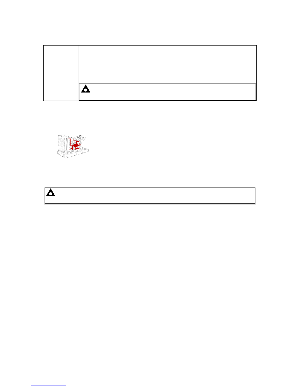
3.4 TERMINAL SPECIFICATION
NOTE: For purchasing additional connector plugs from DSE, please see the section
entitled Maintenance, Spares, Repair and Servicing elsewhere in this document.
Connection Type
Two part connector.
• Male part fitted to
module
• Female part supplied in
module packing case Screw terminal, rising
clamp, no internal
spring.
Example showing cable entry and screw
terminals of a 10 way connector
Minimum Cable Size 0.5mm² (AWG 24)
Maximum Cable Size 2.5mm² (AWG 10)
3.5 POWER SUPPLY REQUIREMENTS
Minimum Supply Voltage 8V continuous
Cranking Dropouts
Able to survive 0V for 100ms providing the supply was at least
10V before the dropout and recovers to 5V afterwards.
Maximum Supply Voltage 35V continuous (60V protection)
Reverse Polarity Protection -35V continuous
Maximum Operating Current
290mA at 12V
140mA at 24V
Maximum Standby Current
75mA at 12V
40mA at 24V
Maximum Current When In
Sleep Mode
40mA at 12V
35mA at 24V
3.5.1 MODULE SUPPLY INSTRUMENTATION DISPLAY
Range 0V-70V DC (note Maximum continuous operating voltage of 35V DC)
Resolution 0.1V
Accuracy 1% full scale (±0.7V)

Specification
11
3.6 VOLTAGE & FREQUENCY SENSING
Measurement Type True RMS conversion
Sample Rate 5kHz or better
Harmonics Up to 11th or better
Input Impedance
300kΩ phase to neutral
Phase To Neutral
15V
(minimum required for sensing frequency
)
to 415V AC
(absolute maximum)
Suitable for 345V AC nominal
(±20% for under/overvoltage detection)
Phase To Phase
25V
(minimum required for sensing frequency
)
to 720V AC
(absolute maximum)
Suitable for 600V AC nominal
(±20% for under/overvoltage detection)
Common Mode Offset From Earth 100V AC (max)
Resolution
1V AC phase to neutral
2V AC phase to phase
Accuracy
±1% of full scale phase to neutral
±2% of full scale phase to phase
Minimum Frequency 3.5 Hz
Maximum Frequency 75.0 Hz
Frequency Resolution 0.1 Hz
Frequency Accuracy ±0.2 Hz
3.7 CURRENT SENSING
Measurement Type True RMS conversion
Sample Rate 5KHz or better
Harmonics Up to 10th or better
Nominal CT Secondary Rating 5A
Maximum Continuous Current 5A
Overload Measurement 3 x Nominal Range setting
Absolute Maximum Overload 50A for 1 second
Burden
0.25VA (0.01Ω current shunts)
Common Mode Offset ±1V peak plant ground to CT common terminal
Resolution 0.5% of 5A
Accuracy ±1% of Nominal (5A) (excluding CT error)
Specification
12
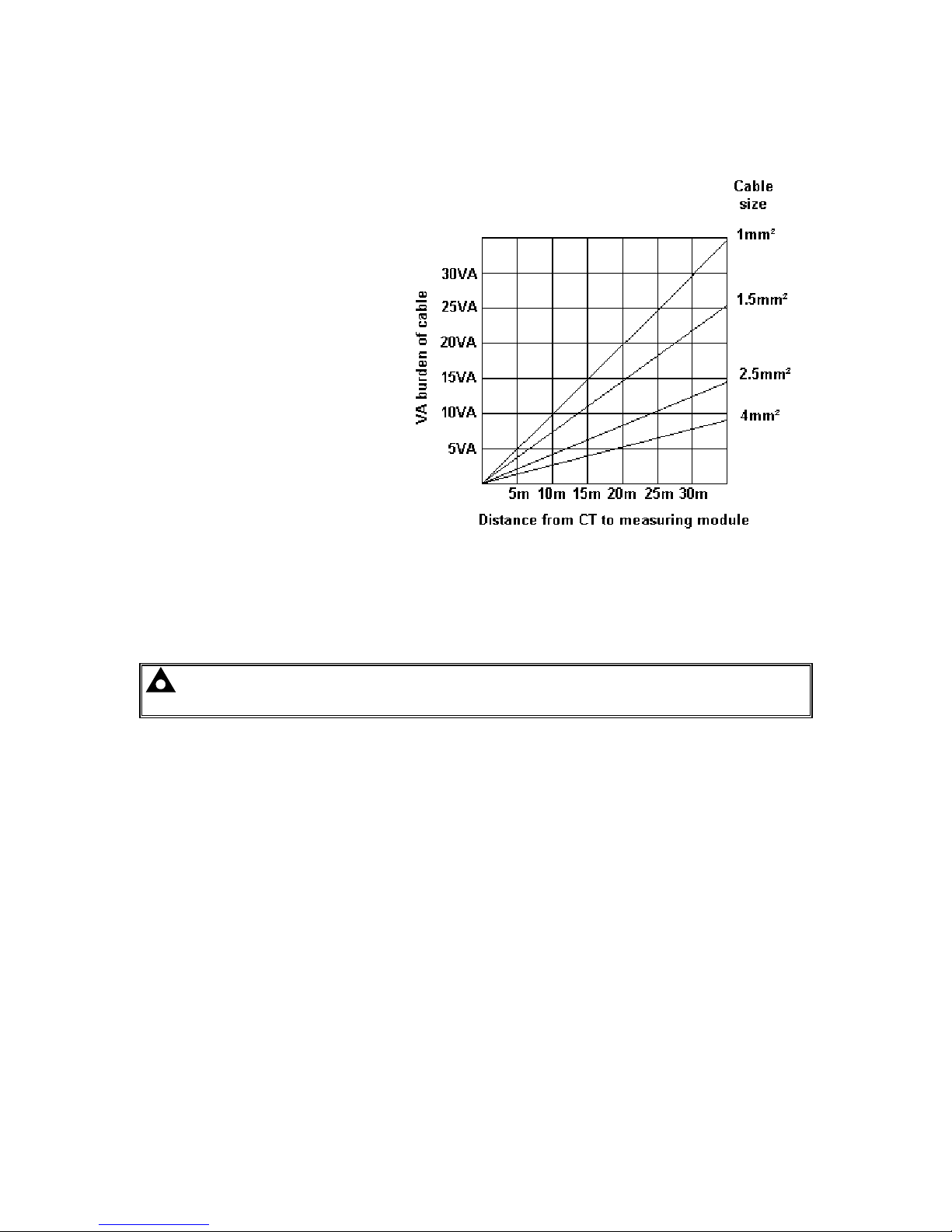
3.7.1 VA RATING OF THE CTS
The VA burden of the module on the CTs is 0.5VA. However depending upon the type and length of
cabling between the CTs and the module, CTs with a greater VA rating than the module are required.
The distance between the CTs and the
measuring module should be
estimated and cross-referenced
against the chart opposite to find the
VA burden of the cable itself.
If the CTs are fitted within the
alternator top box, the star point
(common) of the CTs should be
connected to system ground (earth) as
close as possible to the CTs. This
minimises the length of cable used to
connect the CTs to the DSE module.
Example.
If 1.5mm² cable is used and the
distance from the CT to the measuring
module is 20m, then the burden of the
cable alone is approximately 15VA. As
the burden of the DSE controller is
0.5VA, then a CT with a rating of at
least 15+0.5V = 15.5VA must be used.
If 2.5mm² cables are used over the
same distance of 20m, then the
burden of the cable on the CT is
approximately 7VA. CT’s required in
this instance is at least 7.5VA (7+0.5).
NOTE: Details for 4mm² cables are shown for reference only. The connectors on the DSE
modules are only suitable for cables up to 2.5mm².
Specification
13
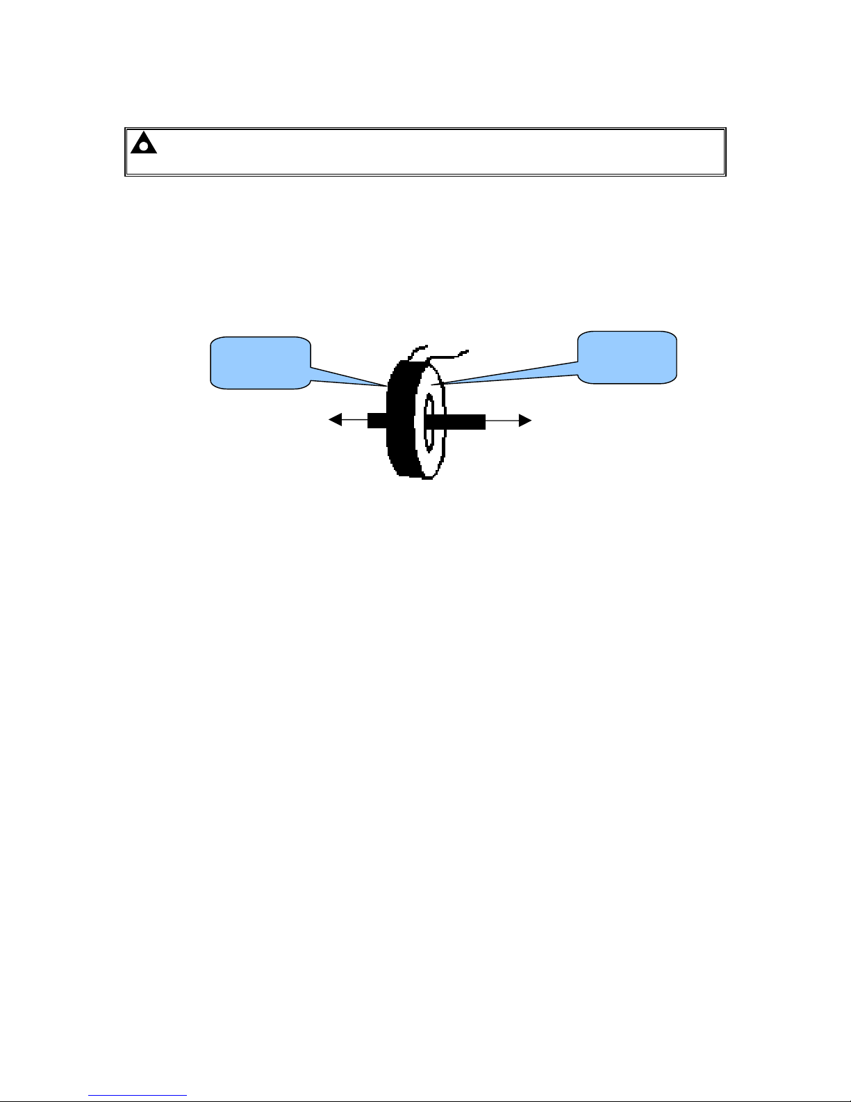
3.7.2 CT POLARITY
NOTE: Take care to ensure correct polarity of the CT primary as shown above. If in doubt,
check with the CT supplier.
Take care to ensure the correct polarity of the CTs. Incorrect CT orientation leads to negative kW
readings when the set is supplying power. Take note that paper stick-on labels on CTs that show the
orientation are often incorrectly placed on the CT (!). It is more reliable to use the labelling in the
case moulding as an indicator to orientation (if available).
To test orientation, run the generator in island mode (not in parallel with any other supply) and load
the generator to around 10% of the set rating. Ensure the DSE module shows positive kW for all
three individual phase readings.
TO GENERATOR
TO LOAD
POLARITY OF CT PRIMARY
3.7.3 CT PHASING
Take particular care that the CTs are connected to the correct phases. For instance, ensure that the
CT on phase 1 is connected to the terminal on the DSE module intended for connection to the CT for
phase 1.
Additionally ensure that the voltage sensing for phase 1 is actually connected to generator phase 1.
Incorrect connection of the phases as described above results in incorrect power factor (pf)
measurements, which in turn results in incorrect kW measurements.
One way to check for this is to make use of a single-phase load. Place the load on each phase in
turn, run the generator and ensure the kW value appears in the correct phase. For instance if the
load is connected to phase 3, ensure the kW figure appears in phase 3 display and not in the display
for phase 1 or 2.
3.7.4 CT CLASS
Ensure the correct CT type is chosen. For instance if the DSE module is providing overcurrent
protection, ensure the CT is capable of measuring the overload level you wish to protect against, and
at the accuracy level you require.
For instance, this may mean fitting a protection class CT (P10 type) to maintain high accuracy while
the CT is measuring overload currents.
Conversely, if the DSE module is using the CT for instrumentation only (current protection is disabled
or not fitted to the controller), then measurement class CTs can be used. Again, bear in mind the
accuracy you require. The DSE module is accurate to better than 1% of the full-scale current reading.
To maintain this accuracy you should fit Class 0.5 or Class 1 CTs.
You should check with your CT manufacturer for further advice on selecting your CTs
Labelled as
p1,
k
or K
Labelled as
p2,
l
or L

Specification
14
3.8 INPUTS
3.8.1 DIGITAL INPUTS
Number
6 configurable digital inputs
(10 when Analogue Inputs are configured as digital inputs)
Arrangement Contact between terminal and ground
Low Level Threshold 3.2V minimum
High Level Threshold 8.1V maximum
Maximum Input Voltage +60V DC with respect to plant supply negative
Minimum Input Voltage -24V DC with respect to plant supply negative
Contact Wetting Current 6mA typical
Open Circuit Voltage 15V typical
3.8.2 ANALOGUE INPUTS
3.8.2.1 OIL PRESSURE
Measurement Type
Resistance measurement by measuring voltage across sensor with a
fixed current applied
Arrangement Differential resistance measurement input
Measurement Current 11mA ±10%
Full Scale
240Ω
Over Range / Fail
270Ω
Resolution 0.1 Bar (1-2 PSI)
Accuracy
±2% of full scale resistance (±4.8Ω) excluding transducer error
Max Common Mode Voltage ±2V
Display Range 0 bar - 17.2 bar (0PSI - 250PSI) subject to limits of the sensor
3.8.2.2 COOLANT TEMPERATURE
Measurement Type
Resistance measurement by measuring voltage across sensor with a
fixed current applied
Arrangement Differential resistance measurement input
Measurement Current 11mA ±10%
Full Scale
480Ω
Over Range / Fail
540Ω
Resolution
1°C (2°F)
Accuracy
+/-2% of full scale resistance (±9.6Ω) excluding transducer error
Max Common Mode Voltage ±2V
Display Range
0°C - 250°C (32°F - 482°F) subject to limits of the sensor

Specification
15
3.8.2.3 FUEL LEVEL SENSOR
Measurement Type
Resistance measurement by measuring voltage across sensor with
a fixed current applied
Arrangement Differential resistance measurement input
Measurement Current 11mA ±10%
Full Scale
480Ω
Over Range / Fail
540Ω
Resolution 1%
Accuracy
+/-2% of full scale resistance (±9.6Ω) excluding transducer error
Max Common Mode Voltage ±2V
Display Range 0% - 250% subject to limits of the sensor
3.8.2.4 FLEXIBLE SENSOR
Number 2 when Fuel Level Sender is configured as a flexible
Measurement Type
Resistance measurement by measuring voltage across sensor with
a fixed current applied
Arrangement Differential resistance measurement input
Measurement Current 11mA ±10%
Full Scale
480Ω
Over Range / Fail
540Ω
Resolution 1%
Accuracy
+/-2% of full scale resistance (±9.6Ω) excluding transducer error
Max Common Mode Voltage ±2V
Display Range
0% - 250%, 0°C - 250°C (32°F - 482°F) or 0 bar - 17.2 bar (0PSI -
250PSI)subject to limits of the sensor and sensor configuration
3.8.3 CHARGE FAIL INPUT
Minimum Voltage 0V
Maximum Voltage 35V (plant supply)
Resolution 0.2V
Accuracy ± 1% of max measured voltage
Excitation Active circuit constant power output
Output Power 2.5W nominal at 12V and 24V
Current At 12V 210mA
Current At 24V 105mA
The charge fail input is actually a combined input and output. Whenever the generator is required to
run, the terminal provides excitation current to the charge alternator field winding.
When the charge alternator is correctly charging the battery, the voltage of the terminal is close to
the plant battery supply voltage. In a failed charge situation, the voltage of this terminal is pulled
down to a low voltage. It is this drop in voltage that triggers the charge failure alarm. The level at
which this operates and whether this triggers a warning or shutdown alarm is configurable using the
DSE Configuration Suite Software.
Specification
16
3.8.4 MAGNETIC PICKUP
Type Differential input
Minimum Voltage 0.5V RMS
Max Common Mode Voltage ±2V
Maximum Voltage
Clamped to ±70V by transient suppressers, dissipation not to
exceed1W.
Maximum Frequency 10,000 Hz
Resolution 6.25 RPM
Accuracy ±25 RPM
Flywheel Teeth 10 to 500
NOTE: DSE can supply a suitable magnetic pickup device, available in two body thread
lengths:
DSE Part number 020-012 - Magnetic Pickup probe 5/8 UNF 2½” thread length
DSE Part number 020-013 - Magnetic Pickup probe 5/8 UNF 4” thread length
Magnetic Pickup devices can often be ‘shared’ between two or more devices. For example, one
device can often supply the signal to both the DSE module and the engine governor. The possibility
of this depends upon the amount of current that the magnetic pickup can supply.
3.9 OUTPUTS
3.9.1 DC OUTPUTS A & B (FUEL & START)
Type
Normally used as Fuel & Start outputs.
Fully configurable for other purposes if the module is configured to control an
electronic engine.
Rating 10A resistive for 10secs, 5A resistive continuous at plant supply.
3.9.2 CONFIGURABLE VOLT-FREE OUTPUTS C & D
Type Normally used for load switching control
Fully configurable volt-free relays. One normally open and one normal closed.
Rating 8A resistive at 250 V AC
3.9.3 CONFIGURABLE DC OUTPUTS E, F, G & H
Type Fully configurable, supplied from DC supply terminal 2.
Rating 2A resistive continuous at plant supply.
Specification
17
3.10 COMMUNICATION PORTS
USB Port
USB 2.0 Device for connection to PC running DSE configuration suite only.
Max distance 6m (18 yards)
CAN Port
Engine CAN Port
Standard implementation of ‘Slow mode’, up to 250K bits/s
Non-Isolated.
Internal Termination provided (120Ω)
Max distance 40m (133 feet)
NOTE: For additional length, the DSE124 CAN Extender is available. For
more information, refer to DSE Publication: 057-116 DSE124 Operator Manual
3.10.1 COMMUNICATION PORT USAGE
3.10.1.1 CAN INTERFACE
Modules are fitted with the CAN interface as standard and are capable of
receiving engine data from engine CAN controllers compliant with the
CAN standard.
CAN enabled engine controllers monitor the engine’s operating
parameters such as engine speed, oil pressure, engine temperature
(among others) in order to closely monitor and control the engine. The industry standard
communications interface (CAN) transports data gathered by the engine controller interface. This
allows generator controllers to access these engine parameters with no physical connection to the
sensor device.
NOTE: For further details on connection to electronic engines, refer to DSE Publication:
057-004 Electronic Engines And DSE Wiring
Specification
18
3.10.1.2 USB CONNECTION
The USB port is provided to give a simple means of connection between a PC and the controller.
Using the DSE Configuration Suite Software, the operator is then able to control the module, starting
or stopping the generator, selecting operating modes, etc.
Additionally, the various operating parameters (such as output volts, oil pressure, etc.) of the remote
generator are available to be viewed or changed.
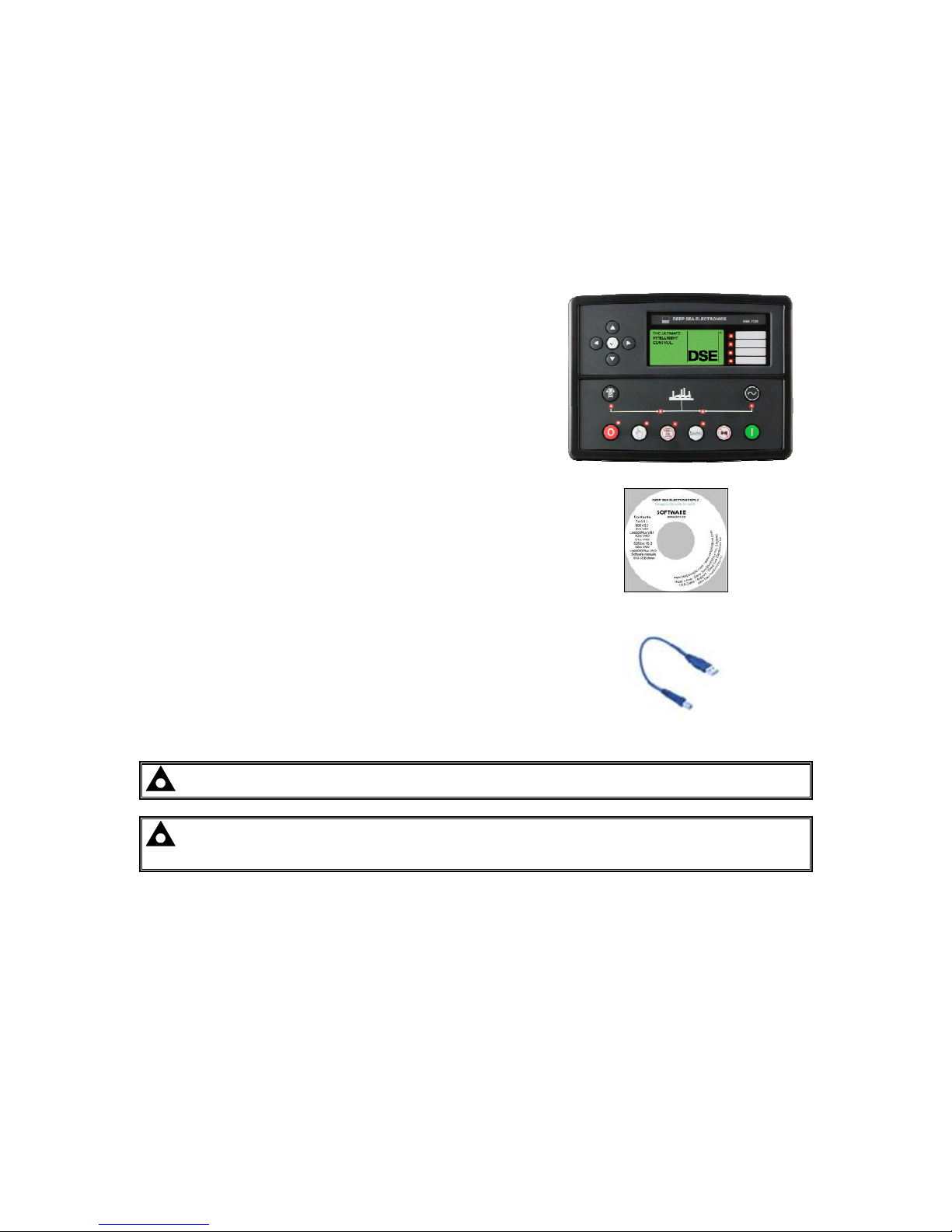
To connect a module to a PC by USB, the following items are required:
• DSE71xx MKII Controller
• DSE Configuration Suite PC Software
(Supplied on configuration suite software CD or
available from www.deepseaplc.com).
• USB cable Type A to Type B.
(This is the same cable as often used between a
PC and a USB printer)
DSE can supply this cable if required :
PC Configuration interface lead (USB type A –
type B) DSE Part No 016-125
NOTE: The DC supply must be connected to the module for configuration by PC.
NOTE: For further details of module configuration, refer to DSE Publication: 057-185
DSE71xx MKII Configuration Software Manual.
Specification
19
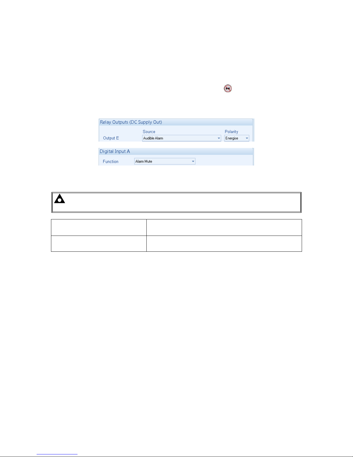
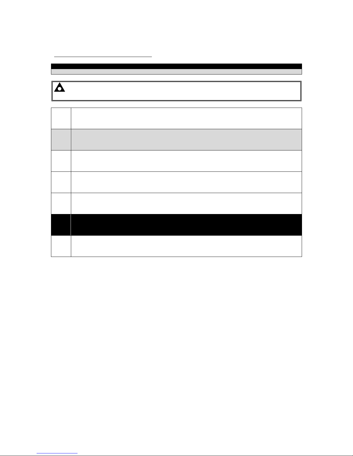
3.11 ADDING AN EXTERNAL SOUNDER
Should an external alarm or indicator be required, this can be achieved by using the DSE
Configuration Suite PC software to configure an auxiliary output for “Audible Alarm”, and by
configuring an auxiliary input for “Alarm Mute” (if required).
The audible alarm output activates and de-activates at the same time as the module’s internal
sounder. The Alarm mute input and internal Lamp Test / Alarm Mute
button activate ‘in parallel’
with each other. Either signal mutes the internal sounder and audible alarm output.
Example of configuration to achieve external sounder with external alarm mute button:
3.12 ACCUMULATED INSTRUMENTATION
NOTE: When an accumulated instrumentation value exceeds the maximum number as
listed below, it resets and begin counting from zero again.
Engine Hours Run
Maximum 99999 hrs 59 minutes
(Approximately 11yrs 4months)
Accumulated Power 999999 kWh / kVArh / kVAh
The number of logged Engine Hours and Number of Starts can be set/reset using the DSE
Configuration Suite PC software. Depending upon module configuration, this may have been PIN
number locked by your generator supplier
Specification
20
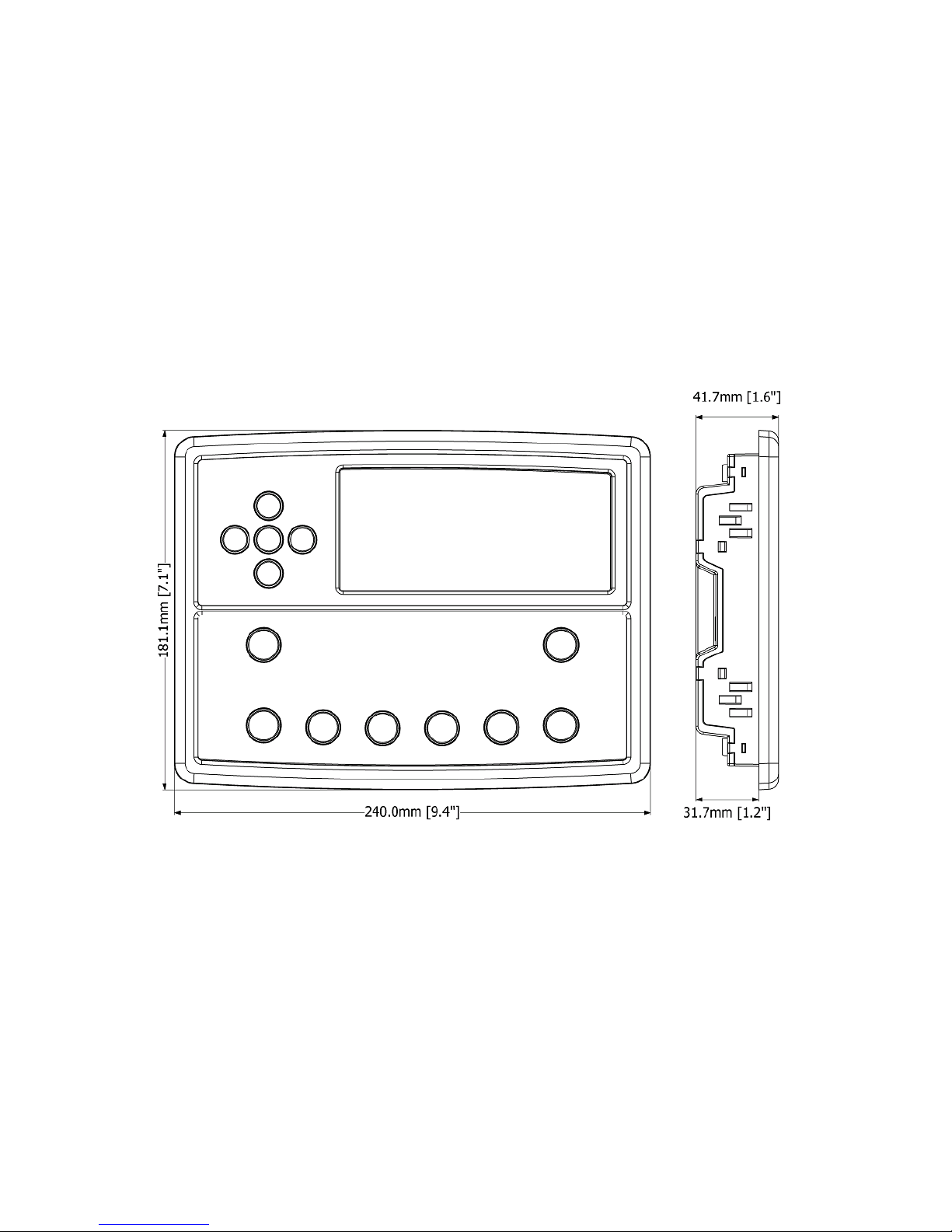
3.13 DIMENSIONS AND MOUNTING
3.13.1 DIMENSIONS
240 mm x 181 mm x 42 mm
(9.4” x 7.1” x 1.6”)
3.13.2 PANEL CUTOUT
220 mm x 160 mm
(8.7” x 6.3”)
3.13.3 WEIGHT
0.7 kg
(1.4 lb)
Specification
21
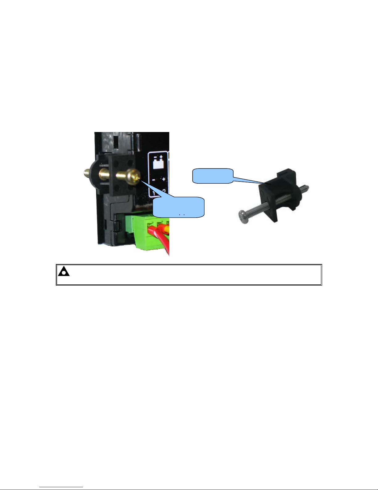
3.13.4 FIXING CLIPS
The module is held into the panel fascia using the supplied fixing clips.
• Withdraw the fixing clip screw (turn anticlockwise) until only the pointed end is protruding
from the clip.
• Insert the three ‘prongs’ of the fixing clip into the slots in the side of the module case.
• Pull the fixing clip backwards (towards the back of the module) ensuring all three prongs of
the clip are inside their allotted slots.
• Turn the fixing clip screws clockwise until they make contact with the panel fascia.
• Turn the screws a little more to secure the module into the panel fascia. Care should be
taken not to over tighten the fixing clip screws.
NOTE: In conditions of excessive vibration, mount the module on suitable anti-vibration
mountings.
Fixing clip
fitted to
Fixing clip
Specification
22
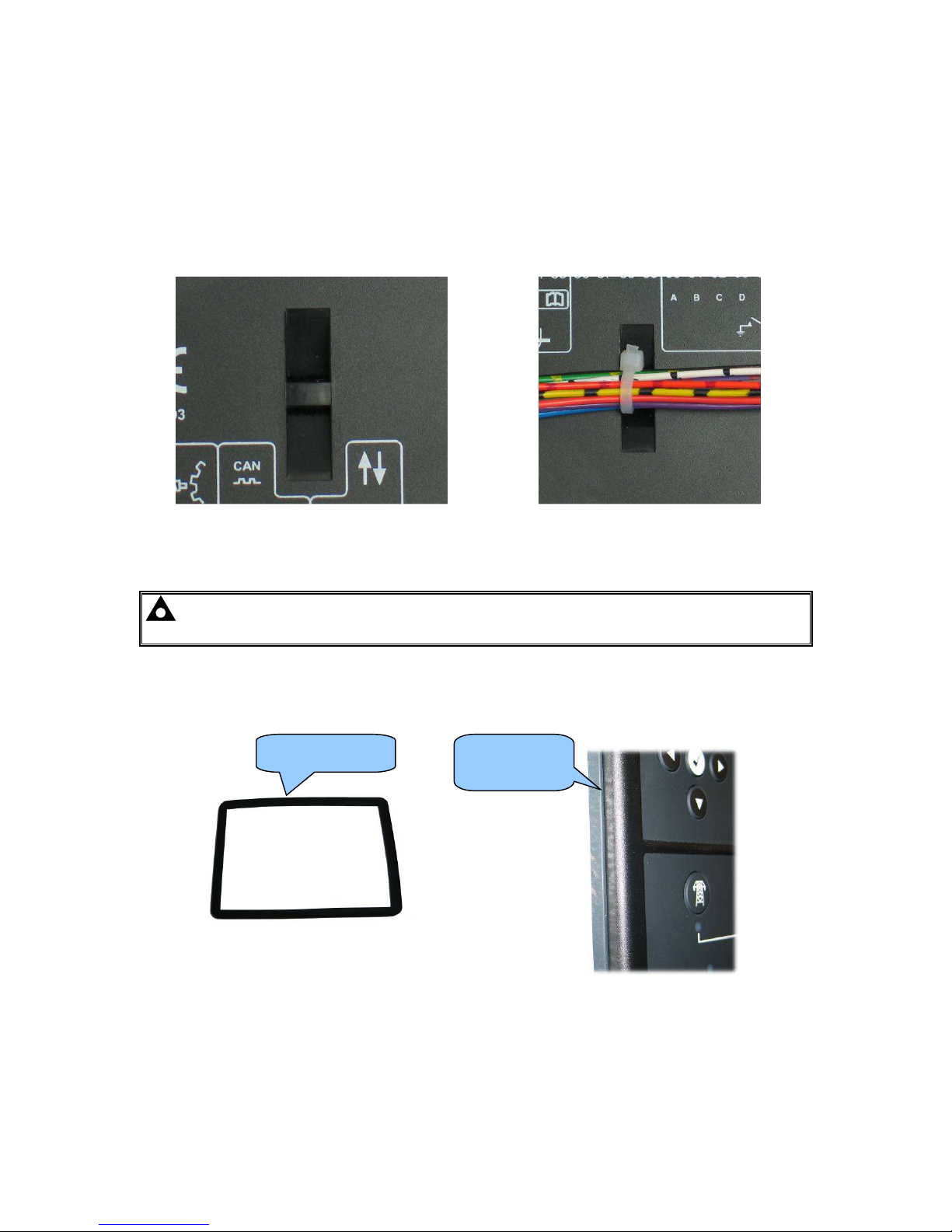
3.13.5 CABLE TIE FIXING POINTS
Integral cable tie fixing points are included on the rear of the module’s case to aid wiring. This
additionally provides strain relief to the cable loom by removing the weight of the loom from the
screw connectors, thus reducing the chance of future connection failures.
Care should be taken not to overtighten the cable tie (for instance with cable tie tools) to prevent the
risk of damage to the module case.
Cable tie fixing point With cable and tie in place
3.13.6 SILICON SEALING GASKET
NOTE: For purchasing an additional silicon gasket from DSE, please see the section
entitled Maintenance, Spares, Repair and Servicing elsewhere in this document.
The optional silicon gasket provides improved sealing between module and the panel fascia.
The gasket is fitted to the module before installation into the panel fascia.
Take care to ensure the gasket is correctly fitted to the module to maintain the integrity of the seal.
Gasket fitted
to module
Sealing gasket

Specification
23
3.13.7 APPLICABLE STANDARDS
BS 4884-1
This document conforms to BS4884-1 1992 Specification for
presentation of essential information.
BS 4884-2 This document conforms to BS4884-2 1993 Guide to content
BS 4884-3 This document conforms to BS4884-3 1993 Guide to presentation
BS EN 60068-2-1
(Minimum temperature)
-30°C (-22°F)
BS EN 60068-2-2
(Maximum temperature)
+70°C (158°F)
BS EN 60950
Safety of information technology equipment, including electrical
business equipment
BS EN 61000-6-2
EMC Generic Immunity Standard (Industrial)
BS EN 61000-6-4
EMC Generic Emission Standard (Industrial)
BS EN 60529
(Degrees of protection
provided by enclosures)
IP65 (front of module when installed into the control panel with the
optional sealing gasket)
IP42 (front of module when installed into the control panel WITHOUT
being sealed to the panel)
UL508
NEMA rating
(Approximate)
12 (Front of module when installed into the control panel with the
optional sealing gasket).
2 (Front of module when installed into the control panel WITHOUT being
sealed to the panel)
IEEE C37.2
(Standard Electrical
Power System Device
Function Numbers and
Contact Designations)
Under the scope of IEEE 37.2, function numbers can also be used to
represent functions in microprocessor devices and software programs.
The controller is device number 11L-8000 (Multifunction device
protecting Line (generator) –module).
As the module is configurable by the generator OEM, the functions
covered by the module vary. Under the module’s factory configuration,
the device numbers included within the module are :
2 – Time Delay Starting Or Closing Relay
3 – Checking Or Interlocking Relay
5 – Stopping Device
6 – Starting Circuit Breaker
8 – Control Power Disconnecting Device
10 – Unit Sequence Switch
11 – Multifunction Device
12 – Overspeed Device
14 – Underspeed Device
26 – Apparatus Thermal Device
27AC – AC Undervoltage Relay
27DC – DC Undervoltage Relay
29 – Isolating Contactor Or Switch
30 – Annunciator Relay
31 – Separate Excitation Device
42 – Running Circuit Breaker
Continued overleaf...

Specification
24
IEEE C37.2
(Standard Electrical
Power System Device
Function Numbers and
Contact Designations)
Continued
50 – Instantaneous Overcurrent Relay
52 – AC Circuit Breaker
53 – Exciter Or DC Generator Relay
54 – Turning Gear Engaging Device
59AC – AC Overvoltage Relay
59DC – DC Overvoltage Relay
62 – Time Delay Stopping Or Opening Relay
63 – Pressure Switch
71 – Level Switch
74 – Alarm Relay
81 – Frequency Relay
83 – Automatic Selective Control Or Transfer Relay
86 – Lockout Relay
In line with our policy of continual development, Deep Sea Electronics, reserve the right to change specification without notice.

Specification
25
3.13.8 ENCLOSURE CLASSIFICATIONS
3.13.8.1 IP CLASSIFICATIONS
The modules specification under BS EN 60529 Degrees of protection provided by enclosures
IP65 (Front of module when module is installed into the control panel with the optional sealing gasket).
IP42 (front of module when module is installed into the control panel WITHOUT being sealed to the panel)
First Digit Second Digit
Protection against contact and ingress of solid objects Protection against ingress of water
0 No protection 0 No protection
1 Protected against ingress solid objects with a
diameter of more than 50 mm. No protection against
deliberate access, e.g. with a hand, but large surfaces
of the body are prevented from approach.
1 Protection against dripping water falling vertically. No harmful
effect must be produced (vertically falling drops).
2 Protected against penetration by solid objects with a
diameter of more than 12 mm. Fingers or similar
objects prevented from approach.
2 Protection against dripping water falling vertically. There
must be no harmful effect when the equipment (enclosure) is
tilted at an angle up to 15° from its normal position (drops
falling at an angle).
3 Protected against ingress of solid objects with a
diameter of more than 2.5 mm. Tools, wires etc. with
a thickness of more than 2.5 mm are prevented from
approach.
3 Protection against water falling at any angle up to 60° from
the vertical. There must be no harmful effect (spray water).
4 Protected against ingress of solid objects with a
diameter of more than 1 mm. Tools, wires etc. with a
thickness of more than 1 mm are prevented from
approach.
4 Protection against water splashed against the equipment
(enclosure) from any direction. There must be no harmful
effect (splashing water).
5 Protected against harmful dust deposits. Ingress of
dust is not totally prevented but the dust must not
enter in sufficient quantity to interface with
satisfactory operation of the equipment. Complete
protection against contact.
5 Protection against water projected from a nozzle against the
equipment (enclosure) from any direction. There must be no
harmful effect (water jet).
6 Protection against ingress of dust (dust tight).
Complete protection against contact.
6 Protection against heavy seas or powerful water jets. Water
must not enter the equipment (enclosure) in harmful
quantities (splashing over).
Specification
26
3.13.8.2 NEMA CLASSIFICATIONS
THE MODULES NEMA RATING (APPROXIMATE)
12 (Front of module when module is installed into the control panel with the optional sealing gasket).
2 (front of module when module is installed into the control panel WITHOUT being sealed to the panel)
NOTE: There is no direct equivalence between IP / NEMA ratings. IP figures shown are
approximate only.
1
IP30
Provides a degree of protection against contact with the enclosure equipment and against a limited amount of falling dirt.
2
IP31
Provides a degree of protection against limited amounts of falling water and dirt.
3
IP64
Provides a degree of protection against windblown dust, rain and sleet; undamaged by the formation of ice on the
enclosure.
3R
IP32
Provides a degree of protection against rain and sleet:; undamaged by the formation of ice on the enclosure.
4 (X)
IP66
Provides a degree of protection against splashing water, windblown dust and rain, hose directed water; undamaged by the
formation of ice on the enclosure. (Resist corrosion).
12/12K
IP65
Provides a degree of protection against dust, falling dirt and dripping non corrosive liquids.
13
IP65
Provides a degree of protection against dust and spraying of water, oil and non corrosive coolants.
Installation
27
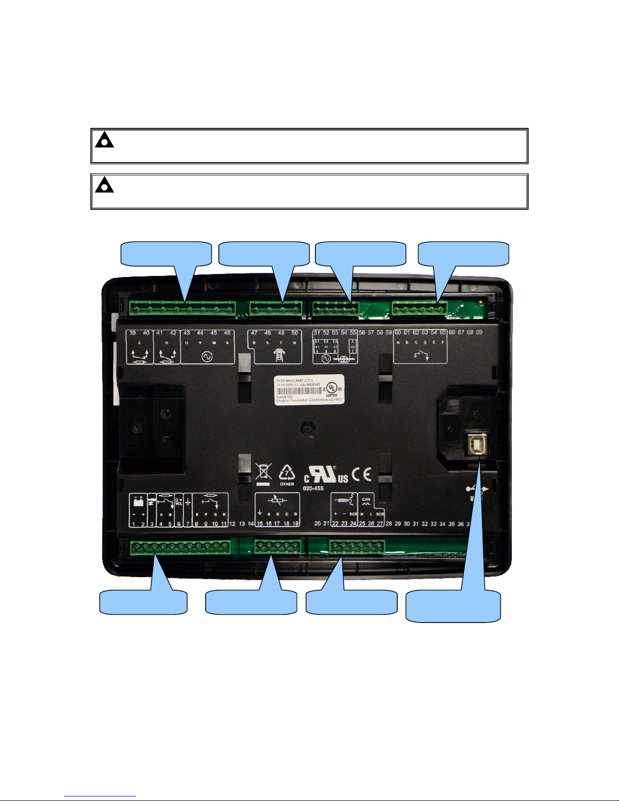
4 INSTALLATION
The module is designed to be mounted on the panel fascia. To aid user connection, icons are used
on the rear of the module to help identify terminal functions. An example of this is shown below.
NOTE: Availability of some terminals depends upon module version. Full details are
given in the section entitled Terminal Description elsewhere in this manual.
NOTE: For dimension and mounting details, see the section entitled Specification,
Dimension and Mounting elsewhere in this document.
Terminals 1-11 Terminals 15-19
Terminals 39-46 Terminals 60-65
USB
PC Configuration
Terminals 51-55 Terminals 47-50
Terminals 22-27
Installation
28
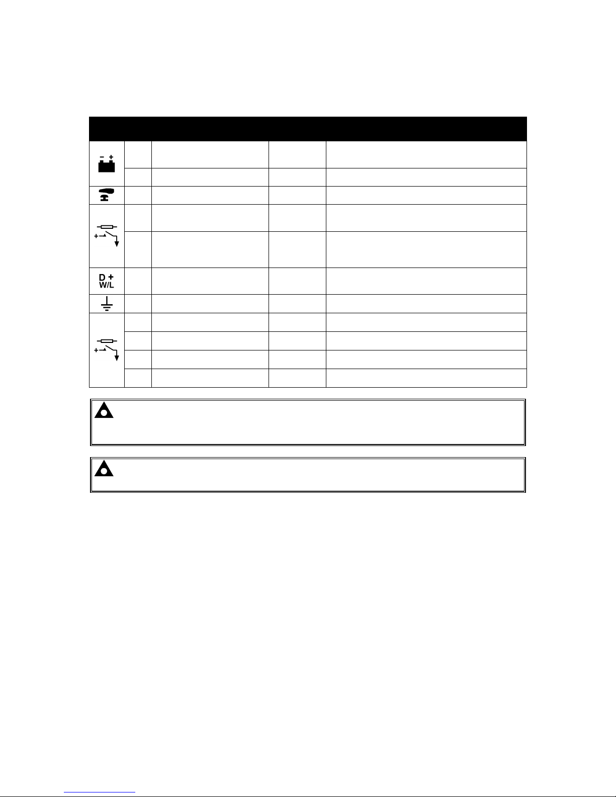
4.1 TERMINAL DESCRIPTION
4.1.1 DC SUPPLY, E-STOP INPUT, DC OUTPUTS & CHARGE FAIL INPUT
Pin
No
Description
Cable
Size
Notes
1
DC Plant Supply Input
(Negative)
2.5mm²
AWG 13
2
DC Plant Supply Input
(Positive)
2.5 mm²
AWG 13
Supplies the module and DC Outputs A, B, E, F, G & H
3 Emergency Stop Input
2.5mm²
AWG 13
Plant Supply Positive. Also supplies DC Outputs A & B.
(Recommended Maximum Fuse 20A)
4 DC Output A (FUEL)
2.5mm²
AWG 13
Plant Supply Positive from terminal 2.
10A for 10secs, 5A resistive continuous
Fixed as FUEL relay if electronic engine is not configured.
5 DC Output B (START)
2.5mm²
AWG 13
Plant Supply Positive from terminal 2.
10A for 10secs, 5A resistive continuous
Fixed as START relay if electronic engine is not
configured.
6 Charge Fail / Excite
2.5mm²
AWG 13
Do not connect to ground (battery negative).
If charge alternator is not fitted, leave this terminal
disconnected.
7 Functional Earth
2.5mm²
AWG 13
Connect to a good clean earth point.
8 DC Output E
1.0mm²
AWG 18
Plant Supply Positive from terminal 2. 2 Amp rated.
9 DC Output F
1.0mm²
AWG 18
Plant Supply Positive from terminal 2. 2 Amp rated.
10 DC Output G
1.0mm²
AWG 18
Plant Supply Positive from terminal 2. 2 Amp rated.
11 DC Output H
1.0mm²
AWG 18
Plant Supply Positive from terminal 2. 2 Amp rated.
NOTE: When the module is configured for operation with an electronic engine, FUEL and
START output requirements may be different. For further details on connection to electronic
engines, refer to DSE Publication: 057-004 Electronic Engines And DSE Wiring
NOTE: For further details of module configuration, refer to DSE Publication: 057-185
DSE71xx MKII Configuration Software Manual.
Installation
29
4.1.2 ANALOGUE SENSORS
Pin
No
Description
Cable
Size
Notes
15 Sensor Common Return
0.5mm²
AWG 20
Return Feed For Sensors
16 Oil Pressure Input
0.5mm²
AWG 20
Connect To Oil Pressure Sensor
17 Coolant Temperature Input
0.5mm²
AWG 20
Connect To Coolant Temperature Sensor
18 Fuel Level Input
0.5mm²
AWG 20
Connect To Fuel Level Sensor
19 Flexible Sensor Input
0.5mm²
AWG 20
Connect To Additional Sensor (User Configurable)
NOTE: It is VERY important that terminal 15 (sensor common) is soundly connected to an
earth point on the ENGINE BLOCK, not within the control panel, and must be a sound
electrical connection to the sensor bodies. This connection MUST NOT be used to provide an
earth connection for other terminals or devices. The simplest way to achieve this is to run a
SEPARATE earth connection from the system earth star point, to terminal 15 directly, and not
use this earth for other connections.
NOTE: If you use PTFE insulating tape on the sensor thread when using earth return
sensors, ensure you do not insulate the entire thread, as this prevents the sensor body from
being earthed via the engine block.
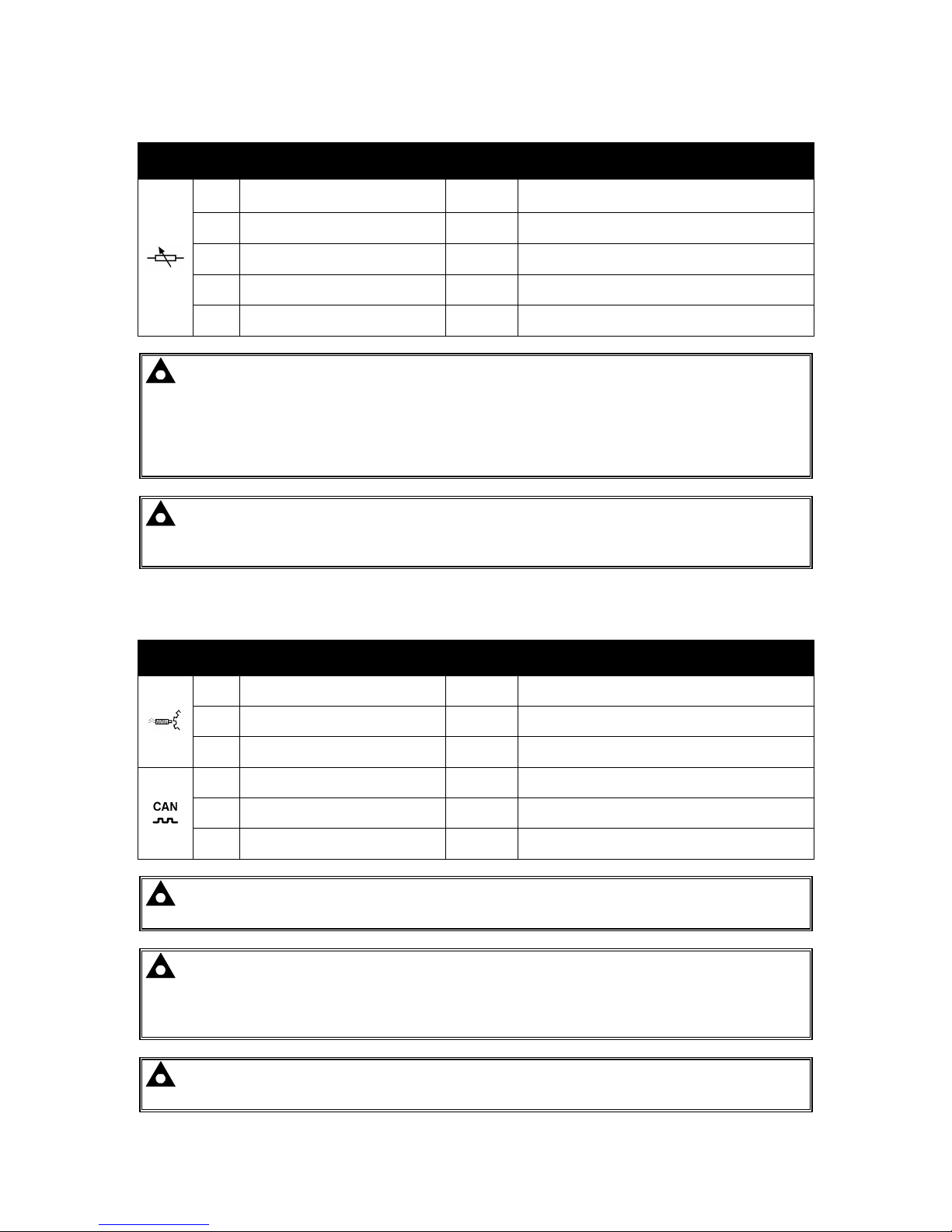
4.1.3 MPU & CAN
Pin
No
Description
Cable
Size
Notes
22 Magnetic Pickup Positive
0.5mm²
AWG 20
Connect To Magnetic Pickup Device
23 Magnetic Pickup Negative
0.5mm²
AWG 20
Connect To Magnetic Pickup Device
24 Magnetic Pickup Screen Shield Connect To Ground At One End Only
25 CAN Port H
0.5mm²
AWG 20
Use Only 120Ω CAN Approved Cable
26 CAN Port L
0.5mm²
AWG 20
Use Only 120Ω CAN Approved Cable
27 CAN Port Screen Shield Use Only 120Ω CAN Approved Cable
NOTE: For further details on connection to electronic engines, refer to DSE Publication:
057-004 Electronic Engines And DSE Wiring
NOTE: Screened 120ΩΩΩΩ impedance cable specified for use with CAN must be used for the
CAN link.
DSE stock and supply Belden cable 9841 which is a high quality 120ΩΩΩΩ impedance cable
suitable for CAN use (DSE part number 016-030)
NOTE: For further details of module configuration, refer to DSE Publication: 057-185
DSE71xx MKII Configuration Software Manual.
Installation
30
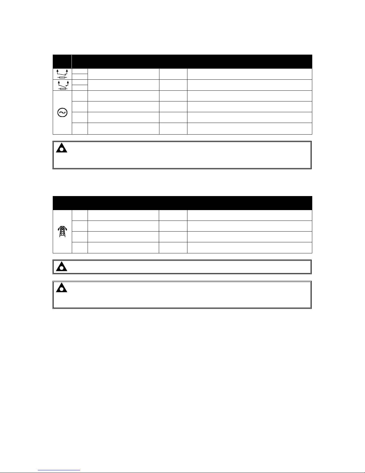
4.1.4 OUTPUT C & D & GENERATOR VOLTAGE & FREQUENCY SENSING
Pin
No
Description
Cable
Size
Notes
39
Normally Close Volt-Free
Output C
1.0mm²
AWG 18
Normally configured to control mains contactor coil
40
41
Normally Open Volt-Free
Output D
1.0mm²
AWG 18
Normally configured to control generator contactor coil
42
43
Generator L1 (U) Voltage
Monitoring
1.0mm²
AWG 18
Connect to generator L1 (U) output (AC)
(Recommend 2A fuse)
44
Generator L2 (V) Voltage
Monitoring
1.0mm²
AWG 18
Connect to generator L2 (V) output (AC)
(Recommend 2A fuse)
45
Generator L3 (W) Voltage
Monitoring
1.0mm²
AWG 18
Connect to generator L3 (W) output (AC)
(Recommend 2A fuse)
46 Generator Neutral (N) Input
1.0mm²
AWG 18
Connect to generator Neutral terminal (AC)
NOTE: The above table describes connections to a three phase, four wire alternator. For
alternative wiring topologies, please see the Alternate Topology Wiring Diagrams section of
this manual.
4.1.5 MAINS VOLTAGE & FREQUENCY SENSING (7120 MKII ONLY)
Pin
No
Description
Cable
Size
Notes
47 Mains L1 (R) Voltage Monitoring
1.0mm²
AWG 18
Connect to Mains L1 (R) output (AC)
(Recommend 2A fuse)
48 Mains L2 (S) Voltage Monitoring
1.0mm²
AWG 18
Connect to Mains L2 (S) output (AC)
(Recommend 2A fuse)
49 Mains L3 (T) Voltage Monitoring
1.0mm²
AWG 18
Connect to Mains L3 (T) output (AC)
(Recommend 2A fuse)
50 Mains Neutral (N) Input
1.0mm²
AWG 18
Connect to Mains Neutral terminal (AC)
NOTE: Terminals 47 to 50 not fitted to DSE7110 MKII
NOTE: The above table describes connections to a three phase, four wire alternator. For
alternative wiring topologies, please see the Alternate Topology Wiring Diagrams section of
this manual.
 Loading...