

DSE DSE6110 MKII, DSE6120 MKII Operator's Manual

057-236 ISSUE: 2
DEEP SEA ELECTRONICS PLC
DSE6110 MKII & DSE6120 MKII
Operator Manual
Document Number: 057-236
Author: Ashley Senior

DSE6110 MKII & DSE6120 MKII Operator Manual
057-236 ISSUE: 2 Page 2 of 116
Deep Sea Electronics Plc
Highfield House
Hunmanby
North Yorkshire
YO14 0PH
ENGLAND
Sales Tel: +44 (0) 1723 890099
Sales Fax: +44 (0) 1723 893303
E-mail: sales@deepseaplc.com
Website: www.deepseaplc.com
DSE6110 MKII & DSE6120 MKII Operator Manual
© Deep Sea Electronics Plc
All rights reserved. No part of this publication may be reproduced in any material form (including
photocopying or storing in any medium by electronic means or other) without the written permission of
the copyright holder except in accordance with the provisions of the Copyright, Designs and Patents
Act 1988.
Applications for the copyright holder’s written permission to reproduce any part of this publication
must be addressed to Deep Sea Electronics Plc at the address above.
The DSE logo and the names DSEGenset®, DSEAts® and DSEPower® are UK registered trademarks
of Deep Sea Electronics PLC.
Any reference to trademarked product names used within this publication is owned by their respective
companies.
Deep Sea Electronics Plc reserves the right to change the contents of this document without prior
notice.
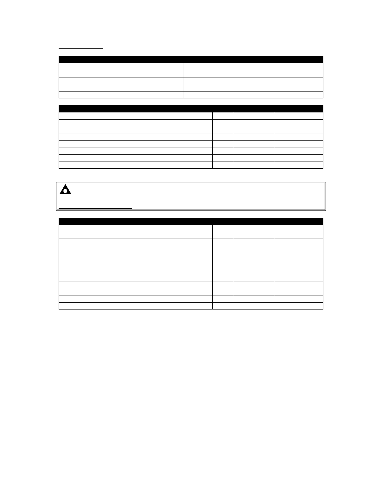
Amendments Since Last Publication
Amd. No.
Comments
1 Initial Release
2
Added cooldown in stop mode, reset maintenance alarm from front panel, audible
alarm output with configurable duration, cooldown at idle speed, EPA tier 4 screen,
user configurable CAN, start and stop in event log, additional alarms
Typeface: The typeface used in this document is Arial. Care should be taken not to mistake the upper
case letter I with the numeral 1. The numeral 1 has a top serif to avoid this confusion.

DSE6110 MKII & DSE6120 MKII Operator Manual
Page 3 of 116 057-236 ISSUE: 2
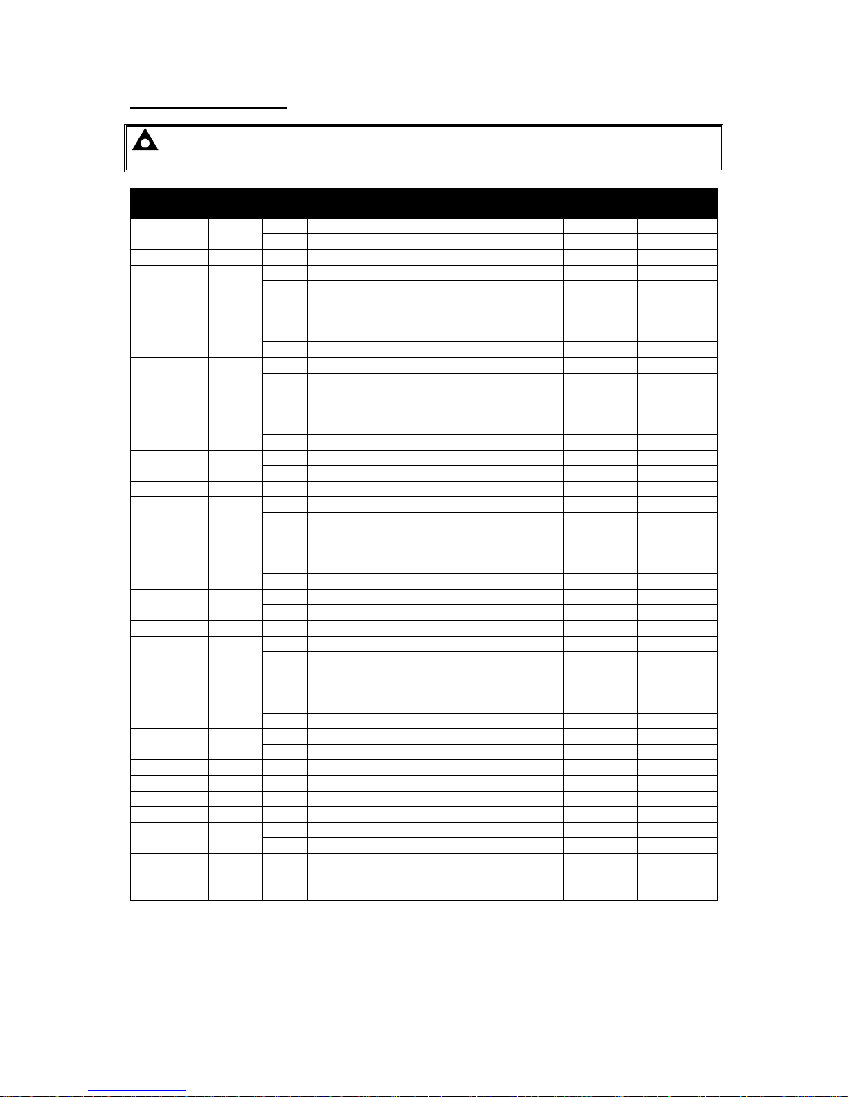
TABLE OF CONTENTS
Section Page
1 INTRODUCTION .................................................................................................. 6
1.1 CLARIFICATION OF NOTATION ............................................................................................ 7
1.2 GLOSSARY OF TERMS .......................................................................................................... 7
1.3 BIBLIOGRAPHY ...................................................................................................................... 9
1.3.1 INSTALLATION INSTRUCTIONS ..................................................................................... 9
1.3.2 TRAINING GUIDES .......................................................................................................... 9
1.3.3 MANUALS ......................................................................................................................... 9
1.3.4 THIRD PARTY DOCUMENTS ........................................................................................ 10
2 SPECIFICATION ................................................................................................ 11
2.1 OPERATING TEMPERATURE .............................................................................................. 11
2.1.1 OPTIONAL SCREEN HEATER OPERATION ................................................................ 11
2.2 REQUIREMENTS FOR UL CERTIFICATION ....................................................................... 11
2.3 TERMINAL SPECIFICATION ................................................................................................ 12
2.4 POWER SUPPLY REQUIREMENTS ..................................................................................... 12
2.4.1 MODULE SUPPLY INSTRUMENTATION DISPLAY ...................................................... 12
2.5 VOLTAGE & FREQUENCY SENSING .................................................................................. 13
2.6 CURRENT SENSING ............................................................................................................. 13
2.6.1 VA RATING OF THE CTS ............................................................................................... 14
2.6.2 CT POLARITY ................................................................................................................. 15
2.6.3 CT PHASING ................................................................................................................... 15
2.6.4 CT CLASS ....................................................................................................................... 15
2.7 INPUTS ................................................................................................................................... 16
2.7.1 DIGITAL INPUTS ............................................................................................................ 16
2.7.2 EMERGENCY STOP ...................................................................................................... 16
2.7.3 ANALOGUE INPUTS ...................................................................................................... 17
2.7.3.1 ANALOGUE INPUT A .............................................................................................. 17
2.7.3.2 ANALOGUE INPUT B .............................................................................................. 18
2.7.3.3 ANALOGUE INPUT C .............................................................................................. 18
2.7.3.4 ANALOGUE INPUT D .............................................................................................. 19
2.7.4 CHARGE FAIL INPUT ..................................................................................................... 19
2.7.5 MAGNETIC PICKUP ....................................................................................................... 20
2.8 OUTPUTS ............................................................................................................................... 20
2.8.1 DC OUTPUTS A & B (FUEL & START) .......................................................................... 20
2.8.2 CONFIGURABLE DC OUTPUTS C, D, E & F ................................................................ 20
2.9 COMMUNICATION PORTS ................................................................................................... 21
2.10 COMMUNICATION PORT USAGE .................................................................................... 22
2.10.1 USB SLAVE PORT (PC CONFIGURATION) .................................................................. 22
2.10.2 ECU PORT (J1939) ......................................................................................................... 23
2.10.2.1 J1939-75 .................................................................................................................. 24
2.10.3 DSENET® (EXPANSION MODULES) ............................................................................. 29
2.11 ADDING AN EXTERNAL SOUNDER ................................................................................ 30
2.12 ACCUMULATED INSTRUMENTATION ............................................................................ 31
2.13 DIMENSIONS AND MOUNTING ........................................................................................ 31
2.13.1 DIMENSIONS .................................................................................................................. 31
2.13.2 PANEL CUTOUT ............................................................................................................. 31
2.13.3 WEIGHT .......................................................................................................................... 31
2.13.4 FIXING CLIPS ................................................................................................................. 32
2.13.5 SILICON SEALING GASKET .......................................................................................... 33
2.13.6 APPLICABLE STANDARDS ........................................................................................... 34
2.13.7 ENCLOSURE CLASSIFICATIONS ................................................................................. 36
2.13.7.1 IP CLASSIFICATIONS ............................................................................................. 36
2.13.7.2 NEMA CLASSIFICATIONS ...................................................................................... 37
3 INSTALLATION ................................................................................................. 38
3.1 TERMINAL DESCRIPTION ................................................................................................... 38

DSE6110 MKII & DSE6120 MKII Operator Manual
057-236 ISSUE: 2 Page 4 of 116
3.2 CONNECTION DESCRIPTIONS ........................................................................................... 39
3.2.1 DC SUPPLY, E-STOP INPUT, DC OUTPUTS & CHARGE FAIL INPUT ....................... 39
3.2.2 ANALOGUE SENSORS, MPU & CAN ............................................................................ 40
3.2.3 DSENET® ....................................................................................................................... 41
3.2.4 GENERATOR & MAINS VOLTAGE & FREQUENCY SENSING ................................... 41
3.2.5 CURRENT TRANSFORMERS ........................................................................................ 42
3.2.5.1 CT CONNECTIONS ................................................................................................. 42
3.2.6 DIGITAL INPUTS ............................................................................................................ 43
3.2.7 USB SLAVE (PC CONFIGURATION) CONNECTOR .................................................... 43
3.3 TYPICAL WIRING DIAGRAM ................................................................................................ 44
3.3.1 DSE6110 MKII TYPICAL WIRING DIAGRAM (3 PHASE 4 WIRE) ................................ 45
3.3.2 DSE6120 MKII TYPICAL WIRING DIAGRAM (3 PHASE 4 WIRE) ................................ 46
3.4 ALTERNATE TOPOLOGY WIRING DIAGRAMS ................................................................. 47
3.4.1 GENERATOR .................................................................................................................. 47
3.4.2 MAINS (DSE6120 MKII ONLY) ....................................................................................... 48
3.5 EARTH SYSTEMS ................................................................................................................. 49
3.5.1 NEGATIVE EARTH ......................................................................................................... 49
3.5.2 POSITIVE EARTH ........................................................................................................... 49
3.5.3 FLOATING EARTH ......................................................................................................... 49
3.6 TYPICAL ARRANGEMENT OF DSENET® .......................................................................... 50
4 DESCRIPTION OF CONTROLS ........................................................................ 51
4.1 DSE6110 MKII ........................................................................................................................ 52
4.2 DSE6120 MKII ........................................................................................................................ 53
4.3 CONTROL PUSH-BUTTONS ................................................................................................ 54
4.4 VIEWING THE INSTRUMENT PAGES .................................................................................. 57
4.4.1 STATUS .......................................................................................................................... 58
4.4.1.1 GENERATOR LOCKED OUT .................................................................................. 58
4.4.1.2 WAITING FOR GENERATOR ................................................................................. 58
4.4.1.3 ENHANCED TIER IV HOME SCREEN ................................................................... 59
4.4.2 ENGINE ........................................................................................................................... 60
4.4.2.1 DPF REGENERATION LAMPS ............................................................................... 61
4.4.3 GENERATOR .................................................................................................................. 62
4.4.4 MAINS (DSE6120 MKII ONLY) ....................................................................................... 63
4.4.5 EXPANSION .................................................................................................................... 64
4.4.6 ALARMS .......................................................................................................................... 65
4.4.6.1 ECU ALARMS (CAN ERROR MESSAGE / DTC) ................................................... 66
4.4.7 EVENT LOG .................................................................................................................... 67
4.4.8 LCD INICATORS ............................................................................................................. 68
4.4.9 USER DEFINED STRINGS ............................................................................................. 68
4.4.10 CONFIGURABLE CAN ................................................................................................... 69
4.4.11 ABOUT ............................................................................................................................ 70
4.4.11.1 MODULE INFORMATION ........................................................................................ 70
4.4.11.2 SUPPORT STRINGS ............................................................................................... 70
5 OPERATION ...................................................................................................... 71
5.1 QUICKSTART GUIDE ............................................................................................................ 71
5.1.1 STARTING THE ENGINE ............................................................................................... 71
5.1.2 STOPPING THE ENGINE ............................................................................................... 72
5.2 STOP/RESET MODE ............................................................................................................. 73
5.2.1 ECU OVERRIDE ............................................................................................................. 73
5.3 MANUAL MODE .................................................................................................................... 74
5.3.1 STARTING SEQUENCE ................................................................................................. 74
5.3.2 ENGINE RUNNING ......................................................................................................... 75
5.3.3 STOPPING SEQUENCE ................................................................................................. 75
5.4 TEST MODE ........................................................................................................................... 76
5.4.1 STARTING SEQUENCE ................................................................................................. 76
5.4.2 ENGINE RUNNING ......................................................................................................... 77
5.4.3 STOPPING SEQUENCE ................................................................................................. 77
5.5 AUTOMATIC MODE .............................................................................................................. 78
5.5.1 WAITING IN AUTO MODE .............................................................................................. 78

DSE6110 MKII & DSE6120 MKII Operator Manual
Page 5 of 116 057-236 ISSUE: 2
5.5.2 STARTING SEQUENCE ................................................................................................. 79
5.5.3 ENGINE RUNNING ......................................................................................................... 80
5.5.4 STOPPING SEQUENCE ................................................................................................. 80
5.6 SCHEDULER ......................................................................................................................... 81
5.6.1 STOP MODE ................................................................................................................... 81
5.6.2 MANUAL MODE .............................................................................................................. 81
5.6.3 TEST MODE .................................................................................................................... 81
5.6.4 AUTO MODE ................................................................................................................... 81
6 PROTECTIONS ................................................................................................. 82
6.1 ALARMS ................................................................................................................................ 82
6.1.1 ECU ALARMS (CAN ERROR MESSAGE / DTC) ........................................................... 83
6.2 INDICATIONS ........................................................................................................................ 84
6.3 WARNING ALARMS .............................................................................................................. 85
6.4 ELECTRICAL TRIP ALARMS ............................................................................................... 89
6.5 SHUTDOWN ALARMS .......................................................................................................... 92
6.6 MAINTENANCE ALARMS ..................................................................................................... 96
6.7 OVER CURRENT ALARM ..................................................................................................... 97
6.7.1 IMMEDIATE WARNING .................................................................................................. 97
6.7.2 INVERSE DEFINITE MINIMUM TIME (IDMT) ALARM................................................... 98
6.7.2.1 CREATING A SPREADSHEET FOR THE OVER CURRENT IDMT CURVE ......... 99
7 FRONT PANEL CONFIGURATION ................................................................. 101
7.1 MAIN CONFIGURATION EDTIOR ...................................................................................... 102
7.1.1 ACESSING THE MAIN CONFIGURATION EDTIOR .................................................... 102
7.1.2 ENTERING PIN ............................................................................................................. 102
7.1.3 EDITING A PARAMETER ............................................................................................. 103
7.1.4 EXITING THE FRONT PANEL CONFIGURATION EDITOR ....................................... 103
7.1.5 ADJUSTABLE PARAMETERS ..................................................................................... 104
7.2 ‘RUNNING’ CONFIGURATION EDITOR ............................................................................. 106
7.2.1 ACCESSING THE ‘RUNNING’ CONFIGURATION EDITOR ....................................... 106
7.2.2 ENTERING PIN ............................................................................................................. 106
7.2.3 EDITING A PARAMETER ............................................................................................. 106
7.2.4 EXITING THE ‘RUNNING’ CONFIGURATION EDITOR .............................................. 107
7.2.5 RUNNING EDITOR PARAMETERS ............................................................................. 107
8 COMMISSIONING ........................................................................................... 108
9 FAULT FINDING .............................................................................................. 109
9.1 STARTING ........................................................................................................................... 109
9.2 LOADING ............................................................................................................................. 109
9.3 ALARMS .............................................................................................................................. 110
9.4 COMMUNICATIONS ............................................................................................................ 110
9.5 INSTRUMENTS .................................................................................................................... 110
9.6 MISCELLANEOUS ............................................................................................................... 111
10 MAINTENANCE, SPARES, REPAIR AND SERVICING .............................. 112
10.1 PURCHASING ADDITIONAL CONNECTOR PLUGS FROM DSE ................................. 112
10.1.1 PACK OF PLUGS ......................................................................................................... 112
10.1.2 INDIVIDUAL PLUGS ..................................................................................................... 112
10.2 PURCHASING ADDITIONAL FIXING CLIPS FROM DSE .............................................. 112
10.3 PURCHASING ADDITIONAL SEALING GASKET FROM DSE ..................................... 112
10.4 DSENET® EXPANSION MODULES ............................................................................... 113
11 WARRANTY ................................................................................................. 114
12 DISPOSAL .................................................................................................... 114
12.1 WEEE (WASTE ELECTRICAL AND ELECTRONIC EQUIPMENT) ............................... 114

Introduction
057-236 ISSUE: 2 Page 6 of 116
1 INTRODUCTION
This document details the installation and operation requirements of the DSE6110 MKII & DSE6120
MKII modules, part of the DSEGenset® range of products.
The manual forms part of the product and should be kept for the entire life of the product. If the
product is passed or supplied to another party, ensure that this document is passed to them for
reference purposes.
This is not a controlled document. DSE do not automatically inform on updates. Any future updates of
this document are included on the DSE website at www.deepseaplc.com
The DSE61xx MKII series is designed to provide differing levels of functionality across a common
platform. This allows the generator OEM greater flexibility in the choice of controller to use for a
specific application.
The DSE61xx MKII series module has been designed to allow the operator to start and stop the
generator, and if required, transfer the load to the generator either manually or automatically.
Additionally, the DSE6120 MKII automatically starts and stops the generator set depending upon the
status of the mains (utility) supply.
The user also has the facility to view the system operating parameters via the text LCD display.
The DSE61xx MKII module monitors the engine, indicating the operational status and fault conditions,
automatically shutting down the engine and giving a true first up fault condition of an engine failure by
the text LCD display.
The powerful ARM microprocessor contained within the module allows for incorporation of a range of
complex features:
Text based LCD display
True RMS Voltage
Current and Power monitoring
USB Communications
Engine parameter monitoring.
Fully configurable inputs for use as alarms or a range of different functions.
Engine ECU interface to electronic engines.
Data Logging
Using a PC and the DSE Configuration Suite software allows alteration of selected operational
sequences, timers, alarms and operational sequences. Additionally, the module’s integral front panel
configuration editor allows adjustment of this information.
Access to critical operational sequences and timers for use by qualified engineers, can be protected
by a security code. Module access can also be protected by PIN code. Selected parameters can be
changed from the module’s front panel.
The module is housed in a robust plastic case suitable for panel mounting. Connections to the module
are via locking plug and sockets.
Introduction
Page 7 of 116 057-236 ISSUE: 2
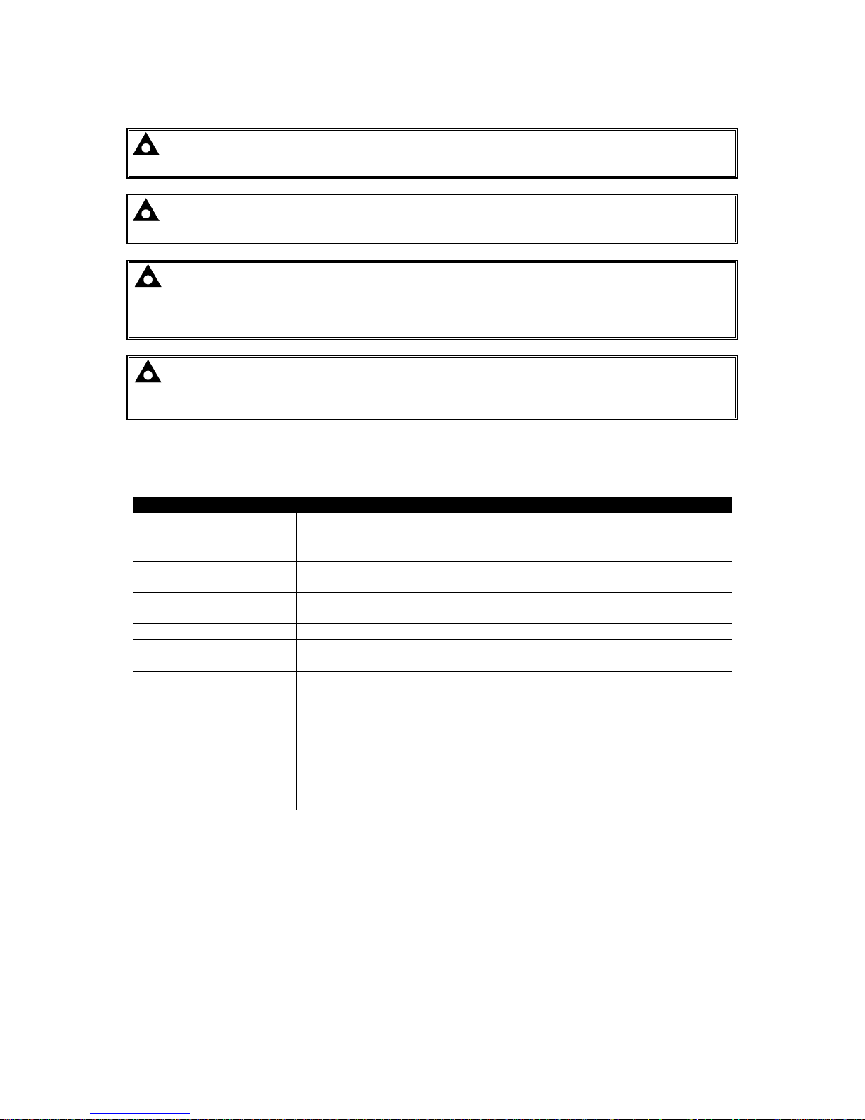
1.1 CLARIFICATION OF NOTATION
Clarification of notation used within this publication.
NOTE:
Highlights an essential element of a procedure to ensure correctness.
CAUTION!
Indicates a procedure or practice, which, if not strictly observed, could
result in damage or destruction of equipment.
WARNING!
Indicates a procedure or practice, which could result in injury to
personnel or loss of life if not followed correctly.
1.2 GLOSSARY OF TERMS
Term
Description
DSE6000 MKII
DSE6xxx MKII
All modules in the DSE6xxx MKII range.
DSE6100 MKII
DSE61xx MKII
All modules in the DSE61xx MKII range.
DSE6110 MKII DSE6110 MKII module/controller
DSE6120 MKII DSE6120 MKII module/controller
CAN Controller Area Network
Vehicle standard to allow digital devices to communicate to one another.
CDMA Code Division Multiple Access.
Cell phone access used in small number of areas including parts of the USA and
Australia.
CT Current Transformer
An electrical device that takes a large AC current and scales it down by a fixed
ratio to a smaller current.
BMS Building Management System
A digital/computer based control system for a building’s infrastructure.
DEF Diesel Exhaust Fluid (AdBlue)
A liquid used as a consumable in the SCR process to lower nitric oxide and
nitrogen dioxide concentration in engine exhaust emissions.
DM1 Diagnostic Message 1
A DTC that is currently active on the engine ECU.
DM2 Diagnostic Message 2
A DTC that was previously active on the engine ECU and has been stored in the
ECU’s internal memory.
DPF Diesel Particulate Filter
A filter fitted to the exhaust of an engine to remove diesel particulate matter or
soot from the exhaust gas.
DPTC Diesel Particulate Temperature Controlled Filter
A filter fitted to the exhaust of an engine to remove diesel particulate matter or
soot from the exhaust gas which is temperature controlled.
DTC Diagnostic Trouble Code
The name for the entire fault code sent by an engine ECU.
ECU/ECM Engine Control Unit/Management
An electronic device that monitors engine parameters and regulates the fuelling.
FMI Failure Mode Indicator
A part of DTC that indicates the type of failure, e.g. high, low, open circuit etc.
GSM Global System for Mobile communications. Cell phone technology used in most
of the World.
Continued over page…

Introduction
057-236 ISSUE: 2 Page 8 of 116
Term
Description
HEST High Exhaust System Temperature
Initiates when DPF filter is full in conjunction with an extra fuel injector in the
exhaust system to burn off accumulated diesel particulate matter or soot.
HMI Human Machine Interface
A device that provides a control and visualisation interface between a human
and a process or machine.
IDMT Inverse Definite Minimum Time
MSC Multi-Set Communication
OC Occurrence Count
A part of DTC that indicates the number of times that failure has occurred.
PGN Parameter Group Number
A CAN address for a set of parameters that relate to the same topic and share
the same transmission rate.
PLC Programmable Logic Controller
A programmable digital device used to create logic for a specific purpose.
SCADA Supervisory Control And Data Acquisition
A system that operates with coded signals over communication channels to
provide control and monitoring of remote equipment
SCR Selective Catalytic Reduction
A process that uses DEF with the aid of a catalyst to convert nitric oxide and
nitrogen dioxide into nitrogen and water to reduce engine exhaust emission.
SIM Subscriber Identity Module.
The small card supplied by the GSM/CDMA provider that is inserted into the cell
phone, GSM modem or DSEGateway device to give GSM/GPRS connection.
SMS Short Message Service
The text messaging service of mobile/cell phones.
SPN Suspect Parameter Number
A part of DTC that indicates what the failure is, e.g. oil pressure, coolant
temperature, turbo pressure etc.
Introduction
Page 9 of 116 057-236 ISSUE: 2
1.3 BIBLIOGRAPHY
This document refers to, and is referred by the following DSE publications which are obtained from
the DSE website: www.deepseaplc.com or by contacting DSE technical support:
support@deepseaplc.com.
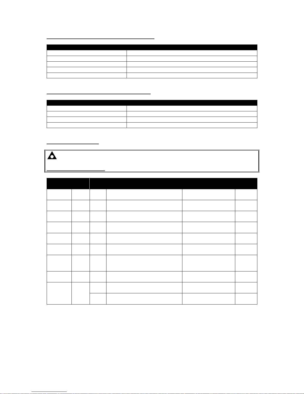
1.3.1 INSTALLATION INSTRUCTIONS
Installation instructions are supplied with the product in the box and are intended as a ‘quick start’
guide only.
DSE Part Description
053-032 DSE2548 LED Expansion Annunciator Installation Instructions
053-033 DSE2130 Input Expansion Installation Instructions
053-034 DSE2157 Output Expansion Installation Instructions
053-173 DSE6110 MKII & DSE6120 MKII Installation Instructions
1.3.2 TRAINING GUIDES
Training guides are provided as ‘hand-out’ sheets on specific subjects during training sessions and
contain specific information regarding to that subject.
DSE
Part Description
056-005 Using CTs With DSE Products
056-010 Over Current Protection
056-022 Breaker Control
056-023 Adding New CAN Files
056-026 kW, kvar, kVA and pf.
056-029 Smoke Limiting
056-030 Module PIN Codes
056-055 Alternate Configurations
056-069 Firmware Update
056-075 Adding Language Files
056-091 Equipotential Earth Bonding
056-092 Best Practices for Wiring Resistive Sensors
056-095 Remote Start Input Functions
1.3.3 MANUALS
Product manuals are obtained from the DSE website: www.deepseaplc.com or by contacting DSE
technical support: support@deepseaplc.com.
DSE
Part Description
057-004 Electronic Engines and DSE Wiring Guide
057-082 DSE2130 Input Expansion Operator Manual
057-083 DSE2157 Output Expansion Operator Manual
057-084 DSE2548 Annunciator Expansion Operator Manual
057-151 DSE Configuration Suite PC Software Installation & Operation Manual
057-224 DSE6110 MKII & DSE6120 MKII Configuration Suite PC Software Manual

Introduction
057-236 ISSUE: 2 Page 10 of 116
1.3.4 THIRD PARTY DOCUMENTS
The following third party documents are also referred to:
Reference
Description
ISBN 1-55937-879-4
IEEE Std C37.2-1996 IEEE Standard Electrical Power System Device
Function Numbers and Contact Designations. Institute of Electrical and
Electronics Engineers Inc
ISBN 0-7506-1147-2 Diesel generator handbook. L.L.J. Mahon
ISBN 0-9625949-3-8 On-Site Power Generation. EGSA Education Committee.

Specification
Page 11 of 116 057-236 ISSUE: 2
2 SPECIFICATION
2.1 OPERATING TEMPERATURE
Module
Description
DSE61xx MKII -30 ºC +70 ºC (-22 ºF +158 ºF )
Display Heater Variants -40 ºC +70 ºC (-40 ºF +158 ºF )
2.1.1 OPTIONAL SCREEN HEATER OPERATION
Screen Heater Function
Description
Turn On When Temperature Falls Below -10 ºC (+14 ºF)
Turn Off When Temperature Rises Above -5 ºC (+23 ºF)
2.2 REQUIREMENTS FOR UL CERTIFICATION
WARNING!: More than one live circuit exists, refer to section entitled Typical Wiring
Diagram elsewhere in this document for more details.
Specification
Description
Screw Terminal
Tightening Torque
• 4.5 lb-in (0.5 Nm)
Conductors
• Terminals suitable for connection of conductor size 13 AWG to 20
AWG (0.5 mm² to 2.5 mm²).
• Conductor protection must be provided in accordance with NFPA 70,
Article 240
• Low voltage circuits (35 V or less) must be supplied from the engine
starting battery or an isolated secondary circuit.
• The communication, sensor, and/or battery derived circuit conductors
shall be separated and secured to maintain at least ¼” (6 mm)
separation from the generator and mains connected circuit
conductors unless all conductors are rated 600 V or greater.
Current Inputs
• Must be connected through UL Listed or Recognized isolating current
transformers with the secondary rating of 5 A max.
Communication
Circuits
• Must be connected to communication circuits of UL Listed equipment
DC Output Pilot Duty
• 0.5 A
Mounting
• Suitable for flat surface mounting in Type 1 Enclosure Type rating
with surrounding air temperature -22 ºF to +122 ºF (-30 ºC to +50 ºC)
• Suitable for pollution degree 3 environments when voltage sensing
inputs do not exceed 300 V. When used to monitor voltages over 300
V device to be installed in an unventilated or filtered ventilation
enclosure to maintain a pollution degree 2 environment.
Operating
Temperature
• -22 ºF to +122 ºF (-30 ºC to +50 ºC)
Specification
057-236 ISSUE: 2 Page 12 of 116
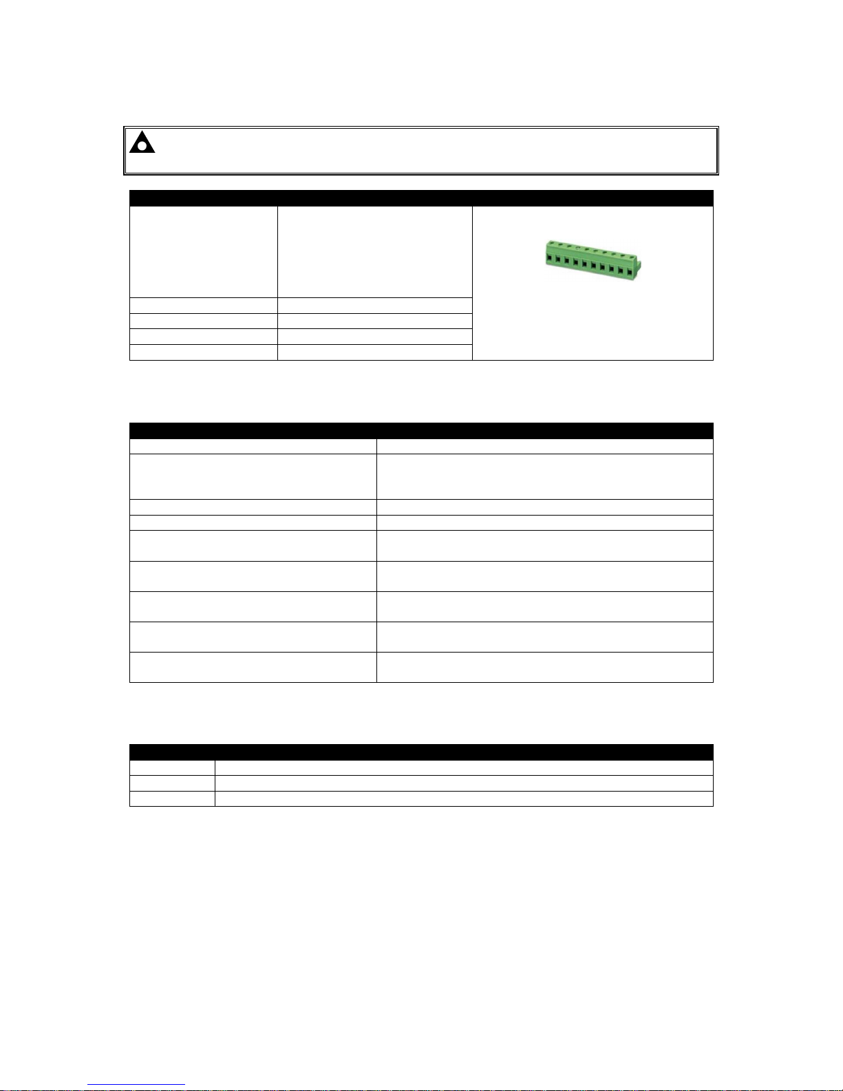
2.3 TERMINAL SPECIFICATION
NOTE: For purchasing additional connector plugs from DSE, please see the section
entitled Maintenance, Spares, Repair and Servicing elsewhere in this document.
Description
Specification
Connection Type
Two part connector.
• Male part fitted to module
• Female part supplied in
module packing case Screw terminal, rising
clamp, no internal spring.
Example showing cable entry and
screw terminals of a 10 way connector
Minimum Cable Size 0.5 mm² (AWG 20)
Maximum Cable Size 2.5 mm² (AWG 13)
Tightening Torque 0.5 Nm (4.5 lb-in)
Wire Strip Length 7 mm (9/32”)
2.4 POWER SUPPLY REQUIREMENTS
Description
Specification
Minimum Supply Voltage 8 V continuous
Cranking Dropouts
Able to survive 0 V for 100 ms providing the supply was
at least 10 V before the dropout and recovers to 5 V
afterwards.
Maximum Supply Voltage 35 V continuous (60 V protection)
Reverse Polarity Protection -35 V continuous
Maximum Operating Current
100 mA at 12 V
105 mA at 24 V
Maximum Standby Current
60 mA at 12 V
55 mA at 24 V
Maximum Current When In Sleep Mode
40 mA at 12 V
35 mA at 24 V
Typical Power
(Controller On, Heater Off)
1.2 W to 2.4 W
Typical Power
(Controller On, Heater On)
0.7 W to 1.2 W
2.4.1 MODULE SUPPLY INSTRUMENTATION DISPLAY
Description
Specification
Range 0 V to 60 V DC (note Maximum continuous operating voltage of 35 V DC)
Resolution 0.1 V
Accuracy 1 % full scale (±0.35 V)

Specification
Page 13 of 116 057-236 ISSUE: 2
2.5 VOLTAGE & FREQUENCY SENSING
Description
Specification
Measurement Type True RMS conversion
Sample Rate 5 kHz or better
Harmonics Up to 11th or better
Input Impedance
450 kΩ phase to phase
Phase To Neutral
15 V (minimum required for sensing frequency) to 415 V AC
(absolute maximum)
Suitable for 345 V AC nominal (±20 % for under/overvoltage
detection)
Phase To Phase
25 V (minimum required for sensing frequency) to 720 V AC
(absolute maximum)
Suitable for 600 V AC nominal (±20 % for under/overvoltage
detection)
Common Mode Offset From Earth 100 V AC (max)
Resolution
1 V AC phase to neutral
2 V AC phase to phase
Accuracy
±1 % of full scale phase to neutral
±2 % of full scale phase to phase
Minimum Frequency 3.5 Hz
Maximum Frequency 75.0 Hz
Frequency Resolution 0.1 Hz
Frequency Accuracy ±0.2 Hz
2.6 CURRENT SENSING
Description
Specification
Measurement Type True RMS conversion
Sample Rate 5 kHz or better
Harmonics Up to 11th
Nominal CT Secondary Rating 5 A
Maximum Continuous Current 5 A
Overload Measurement 15 A
Absolute Maximum Overload 50 A for 1 second
Burden
0.25 VA (0.01 Ω current shunts)
Common Mode Offset ±1 V peak plant ground to CT common terminal
Resolution 0.5 % of 5 A (±25 mA)
Accuracy ±1 % of Nominal (5 A) (excluding CT error) (±50 mA)
Specification
057-236 ISSUE: 2 Page 14 of 116
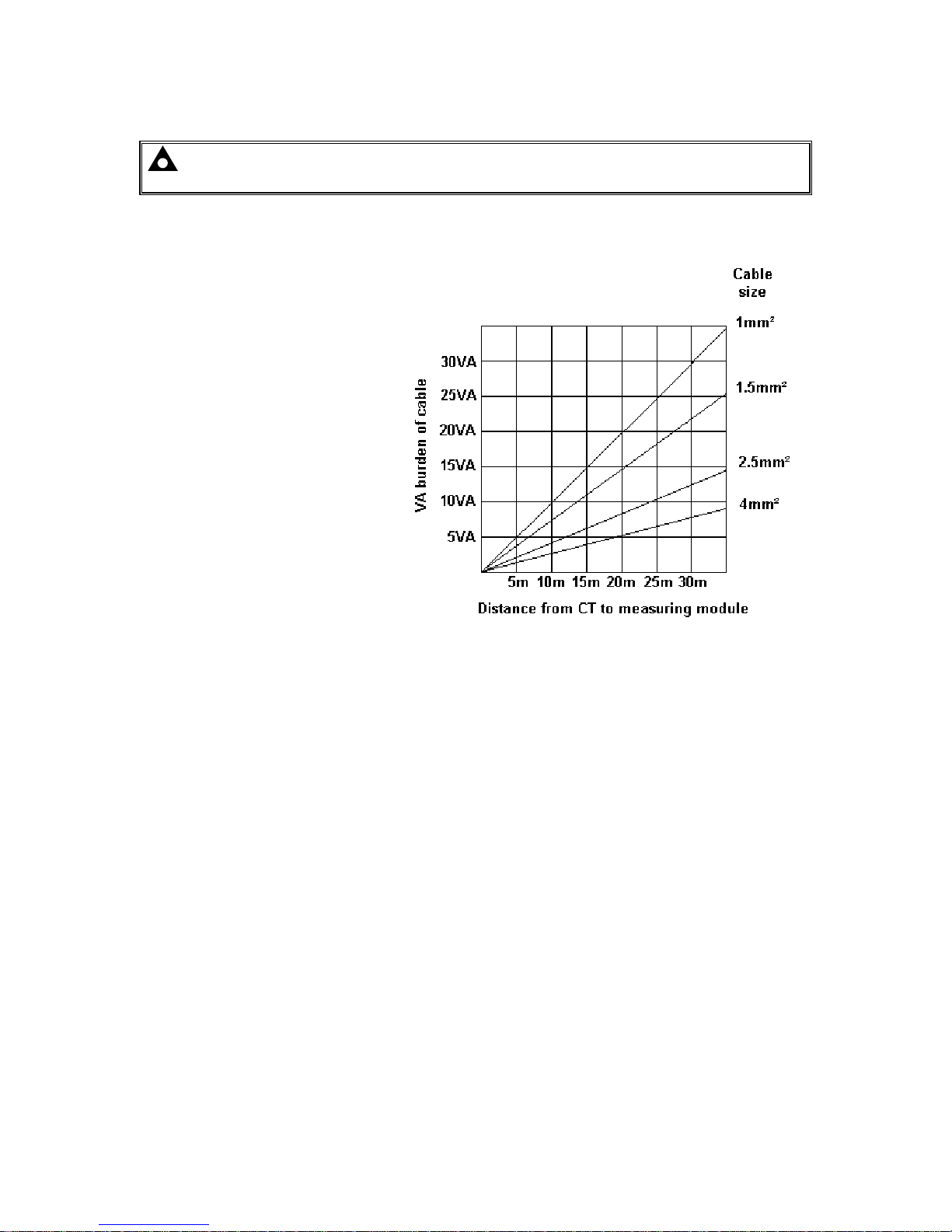
2.6.1 VA RATING OF THE CTS
NOTE: Details for 4 mm² cables are shown for reference only. The connectors on the DSE
modules are only suitable for cables up to 2.5 mm².
The VA burden of the module on the CTs is 0.25 VA. However depending upon the type and length of
cabling between the CTs and the module, CTs with a greater VA rating than the module are required.
The distance between the CTs and the
measuring module should be
estimated and cross-referenced
against the chart opposite to find the
VA burden of the cable itself.
If the CTs are fitted within the
alternator top box, the star point
(common) of the CTs should be
connected to system ground (earth) as
close as possible to the CTs. This
minimises the length of cable used to
connect the CTs to the DSE module.
Example:
If 1.5 mm² cable is used and the
distance from the CT to the measuring
module is 20 m, then the burden of the
cable alone is approximately 15 VA.
As the burden of the DSE controller is
0.25 VA, then a CT with a rating of at
least 15 VA + 0.25 VA = 15.25 VA
must be used. If 2.5 mm² cables are used over the same distance of 20 m, then the burden of the
cable on the CT is approximately 7 VA. CT’s required in this instance is at least 7.25 VA (7 + 0.25).

Specification
Page 15 of 116 057-236 ISSUE: 2
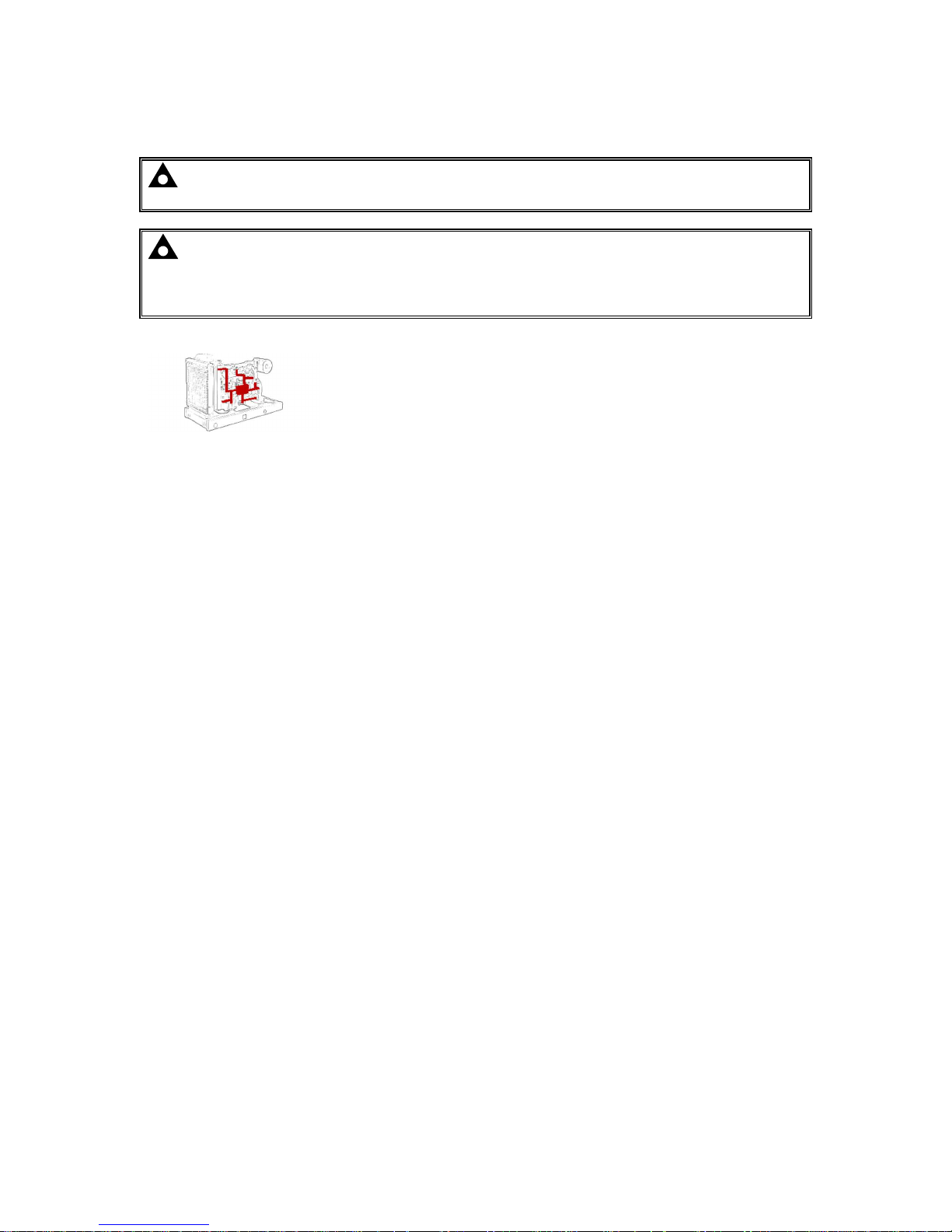
2.6.2 CT POLARITY
NOTE: Take care to ensure correct polarity of the CT primary as shown above. If in doubt,
check with the CT supplier.
Take care to ensure the correct polarity of the CTs. Incorrect CT orientation leads to negative kW
readings when the set is supplying power. Take note that paper stick-on labels on CTs that show the
orientation are often incorrectly placed on the CT. It is more reliable to use the labelling in the case
moulding as an indicator to orientation (if available).
To test orientation, run the generator in island mode (not in parallel with any other supply) and load
the generator to around 10 % of the set rating. Ensure the DSE module shows positive kW for all
three individual phase readings.
To Generator
To Load
Polarity of CT Primary
2.6.3 CT PHASING
Take particular care that the CTs are connected to the correct phases. For instance, ensure that the
CT on phase 1 is connected to the terminal on the DSE module intended for connection to the CT for
phase 1.
Additionally ensure that the voltage sensing for phase 1 is actually connected to generator phase 1.
Incorrect connection of the phases as described above results in incorrect power factor (pf)
measurements, which in turn results in incorrect kW measurements.
One way to check for this is to make use of a single-phase load. Place the load on each phase in turn,
run the generator and ensure the kW value appears in the correct phase. For instance if the load is
connected to phase 3, ensure the kW figure appears in phase 3 display and not in the display for
phase 1 or 2.
2.6.4 CT CLASS
Ensure the correct CT type is chosen. For instance if the DSE module is providing over current
protection, ensure the CT is capable of measuring the overload level required to protect against, and
at the accuracy level required.
For instance, this may mean fitting a protection class CT (P15 type) to maintain high accuracy while
the CT is measuring overload currents.
Conversely, if the DSE module is using the CT for instrumentation only (current protection is disabled
or not fitted to the controller), then measurement class CTs can be used. Again, bear in mind the
accuracy required. The DSE module is accurate to better than 1% of the full-scale current reading. To
maintain this accuracy, fit a Class 0.5 or Class 1 CT.
Check with the CT manufacturer for further advice on selecting CTs Inputs
Labelled as
p1, k or K
Labelled as
p2, l or L

Specification
057-236 ISSUE: 2 Page 16 of 116
2.7 INPUTS
2.7.1 DIGITAL INPUTS
Description
Specification
Number
6 configurable digital inputs
(10 when Analogue Inputs are configured as digital inputs)
Arrangement Contact between terminal and ground
Low Level Threshold 3.2 V minimum
High Level Threshold 8.1 V maximum
Maximum Input Voltage +60 V DC with respect to plant supply negative
Minimum Input Voltage -24 V DC with respect to plant supply negative
Contact Wetting Current 5 mA typical
Open Circuit Voltage 12 V typical
2.7.2 EMERGENCY STOP
Description
Specification
Arrangement Contact between terminal and module supply positive
Closed Threshold 8.1 V minimum
Open Threshold 3.2 V maximum
Maximum Input Voltage
+35 V DC with respect to plant supply negative
(60 V protection for 1 minute)
Minimum Input Voltage -24 V DC with respect to plant supply negative
Open Circuit Voltage 0 V

Specification
Page 17 of 116 057-236 ISSUE: 2
2.7.3 ANALOGUE INPUTS
Analogue Inputs A, B, C & D are flexible within the DSE6110 MKII & 6120 MKII modules
2.7.3.1 ANALOGUE INPUT A
Description
Specification
Input Type
Flexible: Configured for Oil Sensor in the DSE default
configuration.
Flexible Options: Not used, Digital Input, Flexible Analogue & Oil
Sensor
Flexible Input Selection
Pressure Sensor
Percentage Sensor
Temperature Sensor
Flexible Measured Quantity
(Analogue Input A only)
Current
Restive
Voltage
Resistive Configuration
Description
Specification
Measurement Type
Resistance measurement by measuring voltage across sensor
with a fixed current applied
Arrangement Differential resistance measurement input
Measurement Current 15 mA ±10 %
Full Scale
240 Ω
Over Range / Fail
350Ω
Resolution 1 % of display range
Accuracy
+/-2 % of full scale resistance (±4.8 Ω) excluding transducer error
Max Common Mode Voltage ±2 V
Display Range
0 % to 250 %, 0 °C to 250 °C (32 °F to 482 °F) or 0 bar to 17.2 bar
(0 PSI to 250 PSI) subject to limits of the sensor and sensor
configuration
0 V to 10 V Input Configuration
Description
Specification
Full Scale 0 V to 10 V
Resolution 1% of display range
Accuracy +/-2% of full scale voltage (±0.2 V) excluding transducer error
Max Common Mode Voltage ±2 V
Display Range
0 % to 250 %, 0 °C to 250 °C (32 °F to 482 °F) or 0 bar to 17.2 bar
(0 PSI to 250 PSI) subject to limits of the sensor and sensor
configuration

Specification
057-236 ISSUE: 2 Page 18 of 116
4 mA to 20 mA Input Configuration
Description
Specification
Full Scale 0 mA to 20 mA
Resolution 1% of display range
Accuracy +/-2% of full scale resistance (±0.4 mA) excluding transducer error
Max Common Mode Voltage ±2 V
Display Range
0 % to 250 %, 0 °C to 250 °C (32 °F to 482 °F) or 0 bar to 17.2 bar
(0 PSI to 250 PSI) subject to limits of the sensor and sensor
configuration
2.7.3.2 ANALOGUE INPUT B
Description
Specification
Input Type
Flexible: Configured for Coolant Temperature in the DSE default
configuration.
Flexible Options: Not used, Digital Input, Flexible Analogue &
Coolant Temperature
Flexible Input Selection
Pressure Sensor
Percentage Sensor
Temperature Sensor
Measurement Type
Resistance measurement by measuring voltage across sensor with
a fixed current applied
Arrangement Differential resistance measurement input
Measurement Current 10 mA ±10 %
Full Scale
480 Ω
Over Range / Fail
540 Ω
Resolution 1 % of display range
Accuracy
+/-2 % of full scale resistance (±9.6 Ω) excluding transducer error
Max Common Mode Voltage ±2 V
Display Range
0 % to 250 %, 0 °C to 250 °C (32 °F to 482 °F) or 0 bar to 17.2 bar
(0 PSI to 250 PSI) subject to limits of the sensor and sensor
configuration
2.7.3.3 ANALOGUE INPUT C
Description
Specification
Input Type
Flexible: Configured for Fuel Level Sensor in the DSE default
configuration
Flexible Options: Not used, Digital Input, Flexible Analogue & Fuel
Level Sensor
Flexible Input Selection
Pressure Sensor
Percentage Sensor
Temperature Sensor
Measurement Type
Resistance measurement by measuring voltage across sensor
with a fixed current applied
Arrangement Differential resistance measurement input
Measurement Current 10 mA ±10 %
Full Scale
480 Ω
Over Range / Fail
540 Ω
Resolution 1 % of display range
Accuracy
+/-2 % of full scale resistance (±9.6 Ω) excluding transducer error
Max Common Mode Voltage ±2 V
Display Range
0 % to 250 %, 0 °C to 250 °C (32 °F to 482 °F) or 0 bar to 17.2 bar
(0 PSI to 250 PSI) subject to limits of the sensor and sensor
configuration

Specification
Page 19 of 116 057-236 ISSUE: 2
2.7.3.4 ANALOGUE INPUT D
Description
Specification
Input Type
Flexible: Configured for Flexible Sensor, Pressure Sensor in the
DSE default configuration.
Flexible Options: Not used, Digital Input, Flexible Analogue & Oil
Sensor
Flexible Input Selection
Pressure Sensor
Percentage Sensor
Temperature Sensor
Measurement Type
Resistance measurement by measuring voltage across sensor with
a fixed current applied
Arrangement Differential resistance measurement input
Measurement Current 10 mA ±10 %
Full Scale
480 Ω
Over Range / Fail
540 Ω
Resolution 1% of display range
Accuracy
±2 % of full scale resistance (±4.8 Ω) excluding transducer error
Max Common Mode Voltage ±2 V
Display Range
0 % to 250 %, 0 °C to 250 °C (32 °F to 482 °F) or 0 bar to 17.2 bar
(0 PSI to 250 PSI) subject to limits of the sensor and sensor
configuration
2.7.4 CHARGE FAIL INPUT
The charge fail input is actually a combined input and output. Whenever the generator is required to
run, the terminal provides excitation current to the charge alternator field winding.
When the charge alternator is correctly charging the battery, the voltage of the terminal is close to the
plant battery supply voltage. In a failed charge situation, the voltage of this terminal is pulled down to
a low voltage. It is this drop in voltage that triggers the Charge Failure alarm. The level at which this
operates and whether this triggers a warning or shutdown alarm is configurable using the DSE
Configuration Suite Software.
Description
Specification
Minimum Voltage 0 V
Maximum Voltage 35 V (plant supply)
Resolution 0.2 V
Accuracy ±1 % of max measured voltage
Excitation Active circuit constant power output
Output Power 2.5 W nominal at 12 V and 24 V
Current At 12V 210 mA
Current At 24V 105 mA
Specification
057-236 ISSUE: 2 Page 20 of 116
2.7.5 MAGNETIC PICKUP
NOTE: DSE supply a suitable magnetic pickup device, available in two body thread lengths:
DSE Part number 020-012 - Magnetic Pickup probe 5/8 UNF 2 ½” thread length
DSE Part number 020-013 - Magnetic Pickup probe 5/8 UNF 4” thread length
Magnetic Pickup devices can often be ‘shared’ between two or more devices. For example, one
device can often supply the signal to both the DSE module and the engine governor. The possibility of
this depends upon the amount of current that the magnetic pickup can supply.
Description
Specification
Type Differential input
Minimum Voltage 0.5 V RMS
Maximum Voltage 60 V RMS
Max Common Mode Voltage ±2 V
Minimum Frequency 5 Hz
Maximum Frequency 20,000 Hz
Resolution 1 Hz
Accuracy ±1 %
Flywheel Teeth 10 to 500
2.8 OUTPUTS
2.8.1 DC OUTPUTS A & B (FUEL & START)
Description
Specification
Type
Normally used as Fuel & Start outputs.
Fully configurable for other purposes if the module is configured to control an
electronic engine.
Rating 10 A resistive for 10 secs, 5 A resistive continuous at plant supply.
2.8.2 CONFIGURABLE DC OUTPUTS C, D, E & F
Description
Specification
Type Fully configurable, supplied from DC supply terminal 2.
Rating 2 A resistive continuous at plant supply.

Specification
Page 21 of 116 057-236 ISSUE: 2
2.9 COMMUNICATION PORTS
Description
Specification
USB Slave Port
Type B USB 2.0
For connection to PC running DSE Configuration Suite
Max distance 6 m (20 feet)
CAN Port
NOTE: For additional length, the DSE124 CAN Extender is
available. For more information, refer to DSE Publication: 057-116
DSE124 Operator Manual
Engine CAN Port
Standard implementation of ‘Slow mode’, up to 250 Kbits/s
Non-Isolated.
Internal Termination provided (120 Ω)
Max distance 40 m (133 feet)
DSENet®
(Expansion Comms) Port
Non-isolated
Data connection 2 wire + common
Half Duplex
Baud Rate of 115 kbaud
Internal termination fitted (120 Ω)
Max common mode offset ±5 V
Max distance 1.2 km (¾ mile)
Specification
057-236 ISSUE: 2 Page 22 of 116
2.10 COMMUNICATION PORT USAGE
2.10.1 USB SLAVE PORT (PC CONFIGURATION)
NOTE: DSE stock 2 m (6.5 feet) USB type A to type B cable, DSE Part Number: 016-125.
Alternatively they are purchased from any PC or IT store.
NOTE: The DC supply must be connected to the module for configuration by PC.
NOTE: For further details of module configuration, refer to DSE Publication: 057-224
DSE6110 MKII & 6120 MKII Configuration Software Manual
The USB port is provided to give a simple means of connection between a PC and the controller.
Using the DSE Configuration Suite Software, the operator is then able to control the module, starting
or stopping the engine, selecting operating modes, etc.
Additionally, the various operating parameters (such as coolant temperature, oil pressure, etc.) of the
engine are available to be viewed or changed.
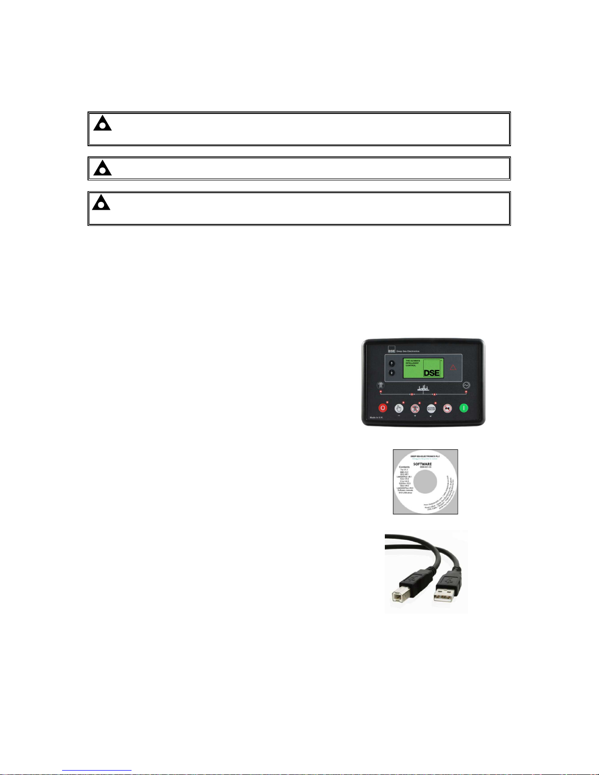
To connect a module to a PC by USB, the following items are required:
DSE6110 MKII & DSE6120 MKII Controller
DSE Configuration Suite PC Software
(Supplied on configuration suite software CD or available
from www.deepseaplc.com).
USB cable Type A to Type B.
(This is the same cable as often used between a PC and a
USB printer)
Specification
Page 23 of 116 057-236 ISSUE: 2
2.10.2 ECU PORT (J1939)
NOTE: For further details on connection to electronic engines, refer to DSE Publication:
057-004 Electronic Engines And DSE Wiring
NOTE: Screened 120 ΩΩΩΩ impedance cable specified for use with CAN must be used for the
CAN link.
DSE stock and supply Belden cable 9841 which is a high quality 120 ΩΩΩΩ impedance cable
suitable for CAN use (DSE part number 016-030)
The modules are fitted with a CAN interface as standard and are capable
of receiving engine data from engine ECU/ECMs compliant with the CAN
J1939 standard.
ECU/ECMs monitor the engine’s operating parameters such as speed,
oil pressure, coolant temperature (among others) in order to closely monitor and control the engine.
The industry standard communications interface (CAN) transports data gathered by the engine’s
ECU/ECM using the J1939 protocol. This allows engine controllers such as DSE to access these
engine parameters with no physical connection to the sensor device.
The ECU Port is used for point-to-point cable connection of more than one device and allows for
connection to CAN Scanner, PLC and CAN controllers (to name just a few devices). The operator is
then able to view the various operating parameters.
Specification
057-236 ISSUE: 2 Page 24 of 116
2.10.2.1 J1939-75
NOTE: For further details of module configuration, refer to DSE Publication: 057-224
DSE6110 MKII & 6120 MKII Configuration Software Manual
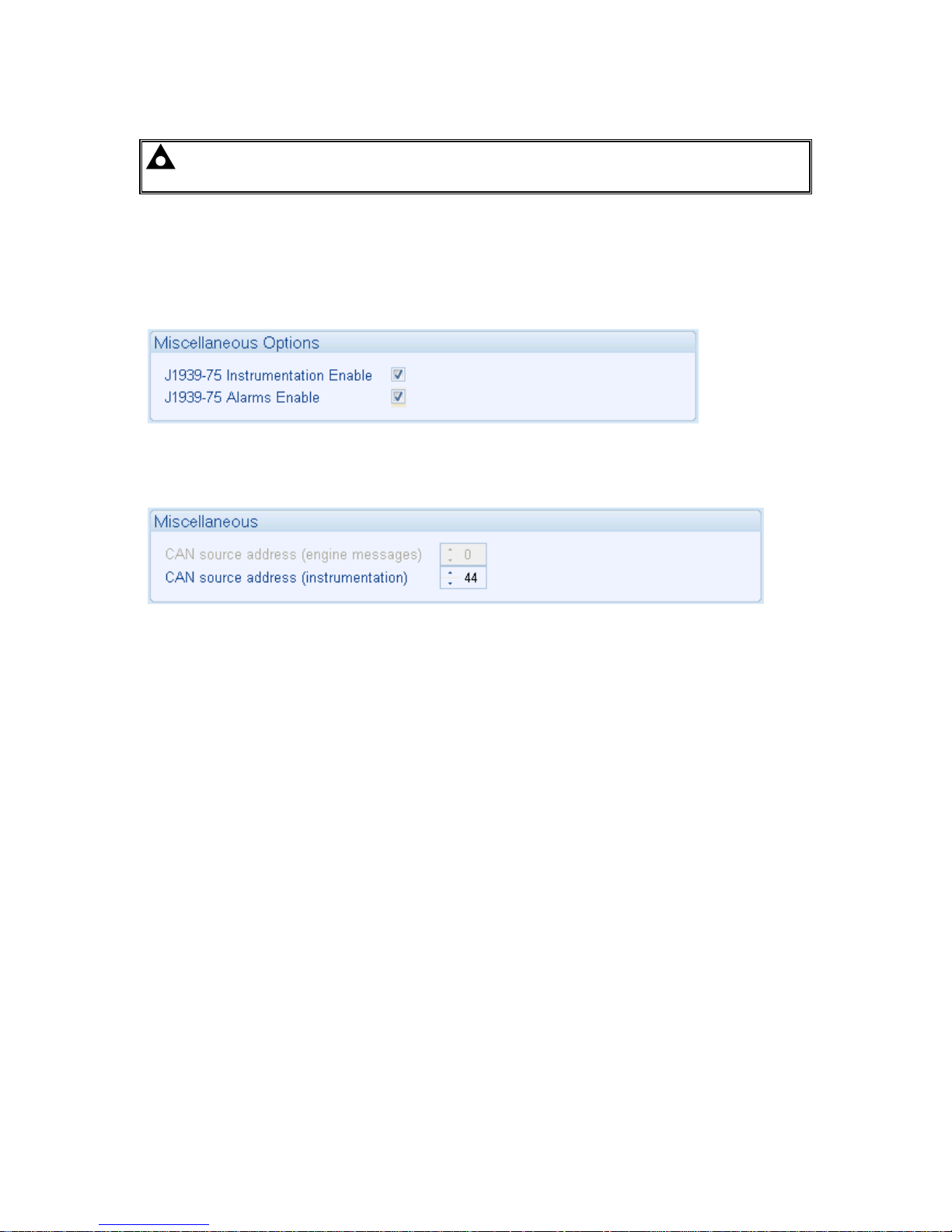
When the J1939-75 is enabled in the module’s configuration, the module’s AC measurements and
alarms are sent onto the CANbus using the ECU Port to be received by an external monitoring device.
There are two check boxes to enable each of the two parts of the interface as shown below, AC
measurement and AC related alarms. The module AC alarms are translated into J1939 DM1
diagnostic messages. There are no additional display screens visible on the module when these
options are selected.
The default CAN source address for additional J1939-75 messages is 44 however this may be
changed by the generator supplier.

Specification
Page 25 of 116 057-236 ISSUE: 2
Transmitted PGNs
PGN Message
PGN
Decimal
Update Rate
ACS 64913 250 ms
DD 65276 1000 ms
DM1 65226 1000 ms
EC2 64895 Request
EEC1 61444 100 ms
EEC4 65214 Request
EFLP1 65263 500 ms
EOI 64914 250 ms
ET1 65262 1000 ms
GAAC 65030 100 ms
GC1 64915 100 ms
GPAAC 65027 100 ms
GPAACP 65026 100 ms
GPAACR 65025 100 ms
GPBAC 65024 100 ms
GPBACP 65023 100 ms
GPBACRP 65022 100 ms
GPCAC 65021 100 ms
GPCACP 65020 100 ms
GPCACR 65019 100 ms
GTACPP 64911 250 ms
GTACE 65018 100 ms
GTACER 64910 250 ms
GTACP 65029 100 ms
GTACR 65028 100 ms
HOURS 65253 Request
VEP1 65271 1000 ms
VREP 64934 100 ms
Specification
057-236 ISSUE: 2 Page 26 of 116
DM1 Conditions
Key Value
Low Fault - Least Severe 17
High Fault - Least Severe 15
Low Fault - Most Severe 1
High Fault - Most Severe 0
Erratic - Incorrect Data 2
Generator Alarm
Condition
SPN Warning FMI
Shutdown FMI
Generator Average AC Frequency Under 2436 17 1
SPN Generator Average Line-Line AC RMS Voltage
Over
2436 15 0
Generator Average Line-Line AC RMS Voltage Under 2440 17 1
Generator Average Line-Line AC RMS Voltage Over 2440 15 0
Generator Average Line-Neutral AC RMS Voltage Under 2444 17 1
Generator Average Line-Neutral AC RMS Voltage Over 2444 15 0
Generator Average AC RMS Current Over 2448 15 0
NOTE: The availability of the Engine Alarm SPN and FMI is dependant upon the engine file
selected within the DSE module’s configuration. Contact DSE technical support:
support@deepseaplc.com for more information.
Engine Alarm Condition
SPN Warning FMI
Shutdown FMI
Fuel Level Low 96 17 1
Oil Pressure Low (Analogue Sensor) 100 17 1
Oil Pressure Low (Digital Input) 100 17 1
Oil Pressure Sensor Fault 100 2 2
Coolant Temperature High (Analogue Sensor) 110 15 0
Coolant Temperature High (Digital Input) 110 15 0
Coolant Temperature Sensor Fault 110 2 2
Charge Alternator Failed 167 17 1
Plant Battery Voltage High 168 15 0
Plant Battery Voltage Low 168 17 1
Overspeed 190 15 0
Underspeed 190 17 1
Specification
Page 27 of 116 057-236 ISSUE: 2
Alternator Measurements
NOTE: For further information regarding the J1939-75 interface, refer to SAE International
J1939 Digital Annex.
PGN
Message PGN SPN Instrument Scaling Units
ACS 64913 3545 Generator Breaker Status List 0 to 7
3546 Mains (Utility) Breaker Status List 0 to 7
GC1 64915 3567 Generator Control Not in Automatic List 0 to 3
GAAC 65030 2436 Generator Average AC Frequency 128 Hz
2440 Generator Average Line Line AC RMS
Voltage
1 V
2444 Generator Average Line Neutral AC RMS
Voltage
1 V
2448 Generator Average AC RMS Current 1 A
GPAAC 65027 2437 Generator Phase A AC Frequency 128 Hz
2441 Generator Phase A Line Line AC RMS
Voltage
1 V
2445 Generator Phase A Line Neutral AC RMS
Voltage
1 V
2449 Generator Phase A AC RMS Current 1 A
GPAACP 65026 2453 Generator Phase A Real Power 1 W
2461 Generator Phase A Apparent Power 1 VA
GPAACR 65025 2457 Generator Phase A Reactive Power 1 var
GPBAC 65024 2438 Generator Phase B AC Frequency 128 Hz
2442 Generator Phase B Line Line AC RMS
Voltage
1 V
2446 Generator Phase B Line Neutral AC RMS
Voltage
1 V
2450 Generator Phase B AC RMS Current 1 A
GPBACP 65023 2454 Generator Phase B Real Power 1 W
2462 Generator Phase B Apparent Power 1 VA
GPBACRP 65022 2458 Generator Phase B Reactive Power 1 var
GPCAC 65021 2439 Generator Phase C AC Frequency 128 Hz
2443 Generator Phase C Line Line AC RMS
Voltage
1 V
2447 Generator Phase C Line Neutral AC RMS
Voltage
1 V
2451 Generator Phase C AC RMS Current 1 A
GPCACP 65023 2455 Generator Phase C Real Power 1 W
2463 Generator Phase C Apparent Power 1 VA
GPCACR 65019 2459 Generator Phase C Reactive Power 1 var
GTACPP 64911 3590 Generator Total Power as Percentage 1 %
GTACE 65018 2468 Generator Accumulated Energy (kWh) 1 kWh
GTACER 64910 3593 Generator Accumulated Energy (kvarh) 1 kvarh
GTACP 65029 2452 Generator Total Real Power 1 W
2460 Generator Total Apparent Power 1 VA
GTACR 65028 2456 Generator Total Reactive Power 1 var
2464 Generator Overall Power Factor
2518 Generator Overall Power Factor Lagging Lead/Lag
Specification
057-236 ISSUE: 2 Page 28 of 116
Generator and Mains (Utility) Breaker Status List
PGN
ACS Value
Description
0 Open
1 Closed
2 to 5 Reserved
6 Not Available
7 Reserved
Generator Control Not In Automatic Status List
PGN
GC1 Value
Description
0 In Automatic
1 Not in Automatic
2 Reserved
3 Not Available
Engine Instrumentation
NOTE: The availability of the Engine Instrumentation PGNs are dependant upon the
engine file selected within the DSE module’s configuration. Contact DSE technical support:
support@deepseaplc.com for more information.
PGN
Message PGN SPN Instrument Scaling Units
DD
65276 96 Fuel Level 0.4 %/bit,
0 % to 100 %
%
EC2 64895 3670 Maximum Crank Attempts Per
Start Attempt
1 count/bit
0 offset
EEC1 61444 190 Engine Speed 0.125 rpm/bit,
0 rpm to 8031.875 rpm
rpm
EEC4 65214 3671 Crank Attempt Count On Present
Start Attempt
1 count/bit
0 offset
EFL_P1 65263 100 Oil Pressure 4 kPa/bit
0 kPa to 1000 kPa
kPa
EOI 64914 3607 Emergency Stop 1 = Estop
0 = No Estop
ET1 65262 110 Coolant Temperature 1 °C/bit,
-40 °C Offset
-40 °C to 210 °C
°C
HOURS 65253 247 Engine Run Hours 0.05 hours/bit,
0 offset
Hours
VEP1 65271 167 Charge Alternator Voltage 0.05 V/bit,
0 V to 3212.75 V
V
168 Plant Battery Voltage 0.05 V/bit,
0 V to 3212.75 V
V
Specification
Page 29 of 116 057-236 ISSUE: 2
2.10.3 DSENET® (EXPANSION MODULES)
NOTE: For further details of module configuration, refer to DSE Publication: 057-224
DSE6110 MKII & 6120 MKII Configuration Software Manual
NOTE: DSE6110 MKII & DSE6120 MKII modules does not support the DSE2510 or DSE2520
display modules.
NOTE: As a termination resistor is internally fitted to the controller, the controller must be
the ‘first’ unit on the DSENet® link. A termination resistor MUST be fitted to the ‘last’ unit on
the DSENet® link. For connection details, refer to section entitled Typical Wiring Diagram
elsewhere in this document.
NOTE: DSE recommend Belden 9841 (or equivalent) cable for DSENet® communication.
This is rated to a maximum cable length of 1.2 km. DSE Stock Belden 9841 cable, DSE Part
Number: 016-030.
DSENet® is the interconnection cable between the host controller and the expansion module(s) and
must not be connected to any device other than DSE equipment designed for connection to the
DSENet®
Description
Specification
Cable Type Two core screened and shielded twisted pair
Cable Characteristics
120 Ω
Low capacitance
Recommended Cable
Belden 9841
Belden 9271
Maximum Cable Length
1200 m (¾ mile) when using Belden 9841 or direct equivalent.
600 m (656 yards) when using Belden 9271 or direct equivalent.
DSENet® Topology “Daisy Chain” Bus with no stubs (spurs)
DSENet® Termination
120 Ω. Fitted internally to host controller. Must be fitted externally to the
‘last’ expansion module.
Maximum Expansion
Modules
Total 6 devices made up of DSE2130 (up to 2), DSE2157 (up to 2),
DSE2548 (up to 2)
This gives the possibility of :
Maximum 16 additional relay outputs (DSE2157)
Maximum 16 additional LED indicators (DSE2548)
Maximum 16 additional inputs (Can be configured as 4 digital inputs &
4 analogue resistive type inputs or 8 digital inputs when using
DSE2130)
Specification
057-236 ISSUE: 2 Page 30 of 116
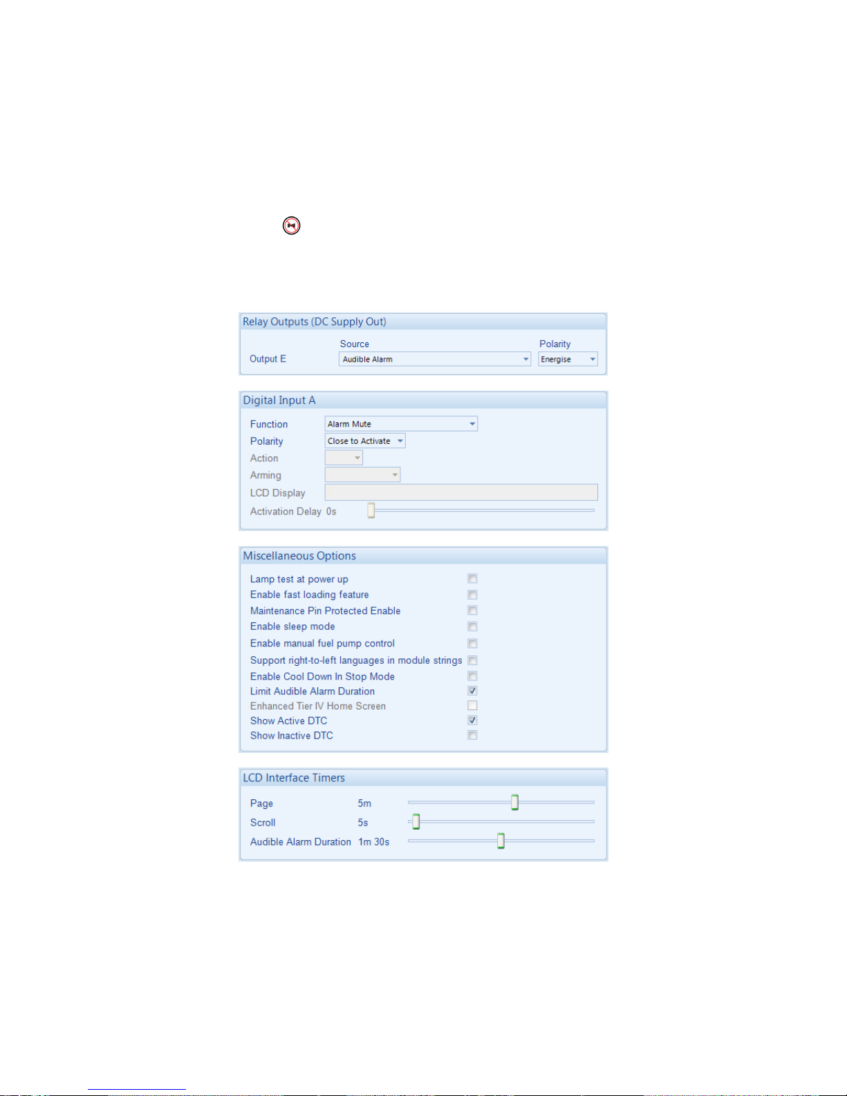
2.11 ADDING AN EXTERNAL SOUNDER
Should an external alarm or indicator be required, this can be achieved by using the DSE
Configuration Suite PC software to configure an auxiliary output for Audible Alarm, and by configuring
an auxiliary input for Alarm Mute (if required).
The Audible Alarm output activates upon a fault occurring and de-activates upon activation of mute
request or after the Audible Alarm Duration time has ceased. The Alarm Mute input, internal
Lamp Test / Alarm Mute button and Audible Alarm Duration time activate ‘in parallel’ with each
other.
Example of configuration to achieve external sounder with external alarm mute button or an automatic
mute after 1 minute and 30 seconds:
 Loading...