

DSE DSE4420 MKII Installation Instructions Manual
OUTPUT SOURCE LIST
0 Not used
1 RESERVED 3
2 Arm safety on alarms
3 Audible alarm
4 Battery over volts warning
5 Battery under volts warning
6 Can ECU data fail
7 Can ECU
error
8 Can ECU fail
9 Can ECU
power
10 Can ECU stop
11 Charge alternator shutdown
12 Charge alternator warning
13 Close gen output
14 Close gen output pulse
15 Close mains output
16 Close mains output pulse
17 Combined mains failure
18 Common alarm
19
Common electrical trip
20 Common shutdown
21 Common warning
22 RESERVED
23 RESERVED
24 RESERVED
25 RESERVED
26 RESERVED
27 RESERVED
28 RESERVED
29 Emergency stop
30 Energise to stop
31 RESERVED
32 RESERVED
33
Fuel relay
34 Gas choke on
35 Gas ignition
36 Generator available
37 Generator over voltage shutdown
38 RESERVED
39 RESERVED
40 Loss of magnetic pickup signal
41
Low fuel level
42 RESERVED
43 RESERVED
44 RESERVED
45 RESERVED
46 RESERVED
47 Open gen output
48 Open gen output pulse
49 Open mains output
50 Open mains output pulse
51 RESERVED
52 RESERVED
53
Preheat during preheat timer
54
Preheat until end of crank
55
Preheat until end of safety timer
56
Preheat until end of warming timer
57 Smoke limiting
58
Start relay
59 RESERVED
60 RESERVED
61 Waiting for manual restore
62 Flexible sender High Shutdown
63 Flexible sender High Warning
64 Flexible sender Low Warning
65 Flexible sender Low Shutdown
44xx – 02 (CAN option) only
44xx
–
01 (Magnetic pickup option) only
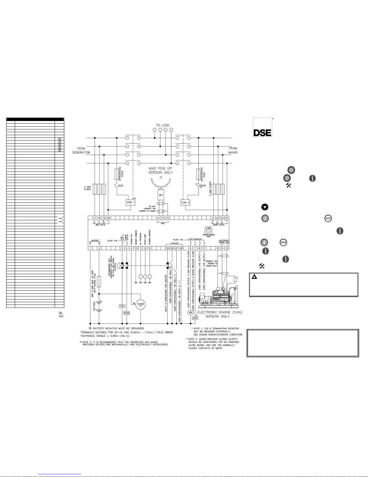
TYPICAL WIRING DIAGRAM
053-079 ISS 5
D E E P S E A E L E C T R O N I C S
DSE4420 INSTALLATION INSTRUCTIONS
This instruction sheet is for DSE4420 MKII controllers only.
For DSE4420 controllers below version 2 use DSE publication
053-056
ACCESSING THE FRONT PANEL CONFIGURATION EDITOR
Ensure the engine is at rest and the module is in stop mode by
pressing the stop/reset button.
Press the stop/reset and down buttons simultaneously.
The configuration icon is displayed, along with the first
configurable parameter.
EDITING A PARAMETER
Press to select the required ‘page’ as detailed in the
configuration tables.
Press (+) to select the next parameter or (-) to select the
previous parameter within the current page.
When viewing the parameter to be changed, press the button.
The value begins to flash.
Press (+) or (-) to adjust the value to the required setting.
Press the save the current value, the value ceases flashing.
Press and hold the button to exit the editor, the configuration
icon will be removed from the display.
NOTE: - pressing and holding the + / - buttons will give autorepeat functionality. Large values can be changed quicker by holding
the buttons for a prolonged period. For instance large timers
increment in 1 second steps to 1 minute, then in 30 second steps to
1 hour, then in 30 minute steps.
DIMENSIONS AND MOUNTING
For flat surface mounting in a Type 1 enclosure to meet UL
requirements.
DIMENSIONS
180mm x 116mm x 42mm
(7.1” x 4.6” x 1.7”)
PANEL CUTOUT
154mm x 98mm
(6” x 3.9”)
Deep Sea Electronics Plc.
Tel:+44 (0)1723 890099
Fax: +44 (0)1723 893303
Email: support@deepseaplc.com
Web: www.deepseaplc.com
Deep Sea Electronics inc.
Phone: +1 (815) 316-8706
Fax: +1 (815) 316- 8708
TOLL FREE (USA only) :
Tel: 1 866 636 9703
Email: support@deepseausa.com
Web: www.deepseausa.com
DSE4420
http://bestgenerator.spb.ru/?page_id=6765
CONFIGURATION PARAMETERS – MODULE (PAGE 1)
101 Contrast 000 (%) 106
Protected start
enable
On (1), off (0)
102 Fast loading enabled On (1), o
ff (0)
107 RESERVED
103 RESERVED 108
Event log display
format
On (1), off (0)
104 Lamp test at startup On (1), o
ff (0)
109 Start in auto On (1), o
ff (0)
105
Power save mode
enable
On (1), off (0) 110
Diagnostic Trouble
Code string
(english only)
enable
On (1), off (0)
CONFIGURATION PARAMETERS –
APPLICATION (PAGE 2) (CAN VERSION MODULE ONLY)
201
Alternate engine speed
On (1), off (0)
203 Can ECU
data fail action
0 (action)
202 Can ECU data fail enable
On (1), off (0)
204 Can ECU
data fail delay
0:00
CONFIGURATION PARAMETERS – INPUTS (PAGE 3)
301 Low oil pressure enable
On (1), off (0)
302
Low oil pressure trip
0.00 bar
303 High engine temperature trip
00 deg c
304 Digital input A source
0 (input source)
305 Digital input A
polarity 0 (polarity)
306 Digital input A action (if source = user config) 0 (action)
307 Digital input A arming (if source = user config) 0 (arming)
308 Digital input A activation delay (if source = user config) 0:00
309 Digital input B source
0 (input source)
310 Digital input B
polarity 0 (polarity)
311 Digital input B action (if source = user config) 0 (action)
312 Digital input B arming (if source = user config) 0 (arming)
313 Digital input B activation delay (if source = user config) 0:00
314 Digital input C source 0
(input source)
315 Digital input C polarity
0 (polarity)
316 Digital input C
action (if source = user config)
0 (action)
317 Digital input C
arming (if source = user config)
0 (arming)
318 Digital input C
activation delay (if source = user config)
0:00
319 Digital input D source
0 (input source)
320 Digital input D polarity
0 (polarity)
321 Digital input D
action (if source = user config)
0 (action)
322 Digital input D
arming (if source = user config)
0 (arming)
323 Digital input D
activation delay (if source = user config)
0:00
324 Analogue input A sensor type
0 (sensor type)
325 Analogue input A sensor selection (pressure senor l
ist)
0 (pressure sensor)
326 Analogue input A (set as digtal) source (oil pressure sender) 0
(input source)
327 Analogue input A
(set as digital) polarity
0 (polarity)
328 Analogue input A
(set as digital) action (if source = user config)
0 (action)
329 Analogue input A (set as digital) arming (if source = user config) 0 (arming)
330 Analogue input A (set as digital) activation delay
(if source = user config)
0:00
331 Analogue input B sensor type
0 (sensor type)
332 Analogue input B sensor selection (temperature
senor list)
0 (temp
sensor)
333 Analogue input B (set as digital) source (temperature sender)
0 (input source)
334 Analogue input B polarity (set as digital)
0 (polarity)
335 Analogue input B
(set as digital) action (if source = user config)
0 (action)
336 Analogue input B (set as digital) arming
(if source = user config)
0 (arming)
337 Analogue input B (set as digital) activation delay
(if source = user config)
0:00
338 Analogue input C sensor type
0 (sensor type)
339 Analogue input C sensor selection (pressure /
temp / percentage)
0 (sensor)
340 Analogue input C (set as digital) source (flexible sender)
0 (input source)
341 Analogue input C
(set as digital) polarity
0 (polarity)
342 Analogue input C (set as digital) action (if source = user config) 0 (action)
343 Analogue input C (set as digital) arming (if source = user config) 0 (arming)
344 Analogue input C (set as digital) activation delay
(if source = user config)
0:00
345 Oil pressure sender open circuit alarm
On (1), off (0)
346 Temperature sender open circuit alarm
On (1), off (0)
CONFIGURATION PARAMETERS – OUTPUTS (PAGE 4)
401 Digital output A source
0 (output source)
402 Digital output
A
polarity 0 (output source polarity)
403 Digital output B source
0 (output
source)
404 Digital output B
polarity 0 (output source polarity)
405 Digital output C source
0 (output source)
406 Digital output C
polarity 0 (output source polarity)
407 Digital output D source
0 (output source)
408 Digital output D
polarity 0 (output source polarity)
409 Digital output E source
0 (output source)
410
Digital output E polarity
0 (output source polarity)
411 Digital output F source
0 (output source)
412
Digital output F polarity
0 (output source polarity)
CONFIGURATION PARAMETERS – TIMERS (PAGE 5)
501
Mains transient delay
507 Smoke limiting off 513 Failed to stop delay
502
Start delay
508 Safety on delay 514
Generator transient delay
503
Preheat timer
509 Warm up time 515
Power save mode delay
504 Crank time 510 Return delay 516 Transfer time
505 Crank rest time 511 Cooling time 517 Breaker trip pulse
506 Smoke limiting 512 Ets solenoid hold 518 Breaker close pulse
= 44xx – 02 (CAN) option only
= 44xx –01 (Magnetic pickup) option only
CONFIGURATION PARAMETERS – GENERATOR (PAGE 6)
601
Alternator fitted
On (1), off (0)
609 Under frequency enable
On (1), off (0)
602 Alternator poles 0
610 Under frequnecy level 0.0 Hz
603 Reserved enable
611 Loading freq
unecy
0.0 Hz
604 Reserved
612 Nominal frequnecy 0.0 Hz
605 Under voltage enabled
On (1), off (0)
613 Over frequecny enable
On (1), off (0)
606 Under v
oltage level 0 V
614 Over frequency
trip
0.0 Hz
607 Loading voltage
0 V
615 AC system AC system
608 Over voltage level
0 V
(see table below)
CONFIGURATION PARAMETERS – MAINS (PAGE 7)
701
AC system
AC system
(see
table)
709
Over voltage level 0 V
702
Mains failure detection
On (1), off (0)
710 Under frequency enable
On (1), off (0)
703 Immediate mains dropout
On (1), off (0)
711 Under frequency level 0.0 Hz
704 Under voltage enable On (1), off (0) 712 Under frequency return 0.0 Hz
705 U
nder voltage level
0 V0
713 Over frequency enable
On (1), off (0)
706 Under voltage return 0
V
714 Over frequency return 0 Hz
707 Over voltage enable On (1), off (0) 715 Over frequency level 0.0 Hz
708 Over voltage return 0
V
CONFIGURATION PARAMETERS – ENGINE (Page 8)
801 Magnetic pickup fitted On (1), off (0)
818 Low battery volts trip 00.0 V
802 Flywheel teeth 000
819 Low battery volts return 00.0 V
803 Start Attempts 0 820
Low battery volts delay
0:00:00
804 RESERVED 821
High battery volts
enable
On (1),
off (0)
805 RESERVED 822
High battery volts
return
00.0 V
806
Gas choke timer
(Gas engine only)
0:00
823
High battery volts
warning
00.0 V
807
Gas on delay
(Gas engine only)
0:00
824
High battery volts
warning delay
00.0 V
808
Gas ignition off delay
(Gas engine only)
0:00
825
Charge alt shutdown
enable
On (1),
off (0)
809
Crank disconnect on Oil
pressure enable
On (1), off (0) 826
Charge alt shutdown
trip
00.0 V
810
Check oil pressure prior
to starting
On (1), off (0) 827
Charge alt shutdown
trip delay
0:00:00
811
Crank disconnect on Oil
threshold
0.00 Bar 828
Charge alt warning trip
enable
On (1),
off (0)
812
Crank disconnect on
frequency
0.0Hz 829
Charge alt warning trip 00.0 V
813
Crank disconnect on
Engine Speed
000 rpm 830
Charge alt warning trip
delay
0:00:00
814 Under speed enable On (1), off (0) 831
Low battery star
t
Arming
On (1),
off (0)
815 Under speed trip 0000 rpm 832
Low battery start
Threshold
00.0 V
816 Over speed trip 0000 rpm 833
Low battery start
Delay
0:00:00
817
Low battery volts
enable
On (1), off (0)
834
Low battery start
Run time
0:00:00
CONFIGURATION PARAMETERS – ALTERNATIVE CONFIGURATION (PAGE 9)
901
Alt config –
Default configuration
Main(1), alternative(0)
902
Alt config –
Enable configuration
On (1), off (0)
903
Alt config
- Al
ternative engine speed
On (1), off (0)
904
Alt
config - Under voltage shutdown enable
On (1), off (0)
905
Alt config
- Under voltage trip
On (1), off (0)
906
Alt config
- Loading voltage
0 v
907
Alt config
- Over voltage trip level 0 v
908
Alt config
- Under frequency enabled
On (1), off (0)
909
Alt config
- Under frequency trip level
0.0 hz
910
Alt config
- Loading frequency
0.0 hz
911
Alt config
- Nominal frequency
0.0 hz
912
Alt config
- Over frequency enabled
On (1), off (0)
913
Alt config
- Over frequency trip level
0.0 hz
914
Alt config - AC system
0 (AC system)
915
Alt config
- Mains failure detection
On (1), off (0)
916
Alt config
- Immediate mains dropout
On (1), off (0)
917
Alt config
- Mains under volt enable
On (1), off (0)
918
Alt config
- Mains under volt trip
0 V
919
Alt config
- Mains under volt return
0 V
920
Alt config
- Mains over volt enable
On (1), off (0)
921
Alt config
- Mains over volt return
0 V
922
Alt config
- Mains over volt trip
0 V
923
Alt config
- Mains under frequency enable
On (1),
off (0)
924
Alt config
- Mains under frequency trip
0.0 Hz
925 Alt config - Mains under frequency return
0.0 Hz
926 Alt config - Mains over frequency enable
On (1), off (0)
927 Alt config - Mains over frequency return
0.0 Hz
928 Alt config - Mains over frequency trip
0.0 Hz
929 Alt config – Alternative under speed shutdown enable
On (1), off (0)
930 Alt config – Alternative under speed shutdown trip
0000 RPM
931 Alt config – Alternative
over
speed shutdown trip
0000 RPM
Output source list overleaf...
CONFIGURATION PARAMETERS – FLEXIBLE SENSOR (PAGE 10)
1001 Flexible sensor alarm arming 0 (Arming)
1002 Flexible sensor - Low
alarm
enable
0 (Action)
1003 Flexible sensor - Low
alarm
trip (units depend upon
sensor type)
0 % /
0.00 bar
/ 0 °C
1004 Flexible sensor - High
alarm
enable
0 (Action)
1005 Flexible sensor - High
alarm
trip (units depend upon sensor type) 0 % /
0.00 bar
/ 0 °C
1006 Flexible sensor - Low warning enable
On (1), Off (0)
1007 Flexible sensor - Low warning trip (units depend upon
sensor type)
0 % /
0.00 bar
/ 0 °C
1008 Flexible sensor – High warning enable
On (1), Off (0)
1009 Flexible sensor – High warning trip (units depend upon
sensor type)
0 % /
0.00 bar
/ 0 °C
CONFIGURATION PARAMETERS – SCHEDULER (Page 11)
1101 Enable scheduler On (1), o
ff (0)
1104
Day
0 (Day, 1
=Monday)
1102
On or off load
On (1), o
ff (0)
1105 Duration 0:00:00
1103 Start time 0:00:00
CONFIGURATION PARAMETERS – TIME AND DAY (Page 12)
1201
Time of day
0:00 1202
Day of week
0 (Day, 1
=Monday)
Parameters with multiple choices use the following identification tables for the parameter values :
INPUT SOURCE LIST
0 User Configured 8 Emergency Stop 16 Oil Pressure Switch
1 Alarm Mute
9 External Panel Lock
17 Remote
Start Off Load
2 Alarm Reset 10 RESERVED 18
Remote Start On Load
3
Alternative Configuration
11 Generator load inhibit 19 Simulate mains available
4 Auto restor inhibit
12
Lamp Test
20 Smoke Limiting
5
Auto start inhibit
13
Low Fuel Level Switch
21 Close Gen / Open Mains
6 Auxilary mains fail
14
RESERVED 22 Open Gen / Close Mains
7 Coolant Temperature Switch 15 Mains load inhibt
INPUT ACTION LIST
INPUT ARMING LIST
Index
Action
Index Arming
0 Electrical Trip
0 Always
1 Shutdown
1 From Safety On
2 Warning
2 From Starting
3 Never
INPUT POLARITY LIST
Index
Action
OUTPUT POLARITY LIST
0 Close to Activate
Index Arming
1 Open to Activate
0 Energise
1 De-energise
CAN DATA FAIL ACTION
Index
Action
CAN DATA FAIL ARMING
0 None
Index Arming
1 Shutdown
0 From Safety On
2 Warning always latched
1 From Starting
FLEXIBLE SENSOR ALARM ACTION LIST
AC SYSTEM
Index
Action
Index Type
0 None
0 2 phase 3 wire (L1-
L2)
1 Shutdown
1 2 phase 3 wire (L1-
L3)
2 Electrical Trip
2 3 phase 3 wire
3 3 phase 4 wire
FLEXIBLE SENSOR TYPE
4 3 phase 4 wire (Delta)
Index Type
5 Single phase 2 wire
0 None
1 Digital Input
2
Percentage sensor
3
Pressure sensor
4
Temperature sensor
SENSOR
SELECTIONS
FOR PERCENTAGE
SENSOR
SELECTIONS FOR
OIL PRESSURE
SENSOR SELECTIONS FOR
COOLANT TEMPERATURE
0 Not used
0 Not used
0 Not used
1 D
ig closed for alarm
1
Dig closed for alarm
1
Dig closed for alarm
2
Dig open for alarm
2 Dig open for
alarm
2
Dig open for alarm
3 VDO ohm (10-
180)
3 VDO
5 bar
3 VDO 120 °C
4 VDO tube (90-
0)
4 VDO
10 bar
4 Datacon high
5 Us ohm (240-
33)
5
Datacon 5 bar
5 Datacon low
6 GM ohm (0-
90)
6
Datacon 10 bar
6 Murphy
7 GM ohm (0-
30)
7
Datacon 7 bar
7 Cummins
8 Ford (73
-
10)
8
Murphy 7 bar
8 PT100
9 User defined
9 CMB812
9 Veglia
10 Veglia
10 Beru
Dig = Digital Switch
11 User defined
11 User defined
http://bestgenerator.spb.ru/?page_id=6765
 Loading...