

Page 1

DSE331 Operator Manual ISSUE 3
DEEP SEA ELECTRONICS PLC
DSE331 ATS Controller Operators Manual
Document Number 057-146
Author: Allan Jones
Page 2
DSE331 Operators Manual
2
Deep Sea Electronics Plc
Highfield House
Hunmanby
North Yorkshire
YO14 0PH
ENGLAND
Sales Tel: +44 (0) 1723 890099
Sales Fax: +44 (0) 1723 893303
E-mail: [email protected]
Website:
www.deepseaplc.com
DSE 331 ATS controller Operators Manual
© Deep Sea Electronics Plc
All rights reserved. No part of this publication may be reproduced in any material form (including photocopying or storing in
any medium by electronic means or other) without the written permission of the copyright holder except in accordance with the
provisions of the Copyright, Designs and Patents Act 1988.
Applications for the copyright holder’s written permission to reproduce any part of this publication should be addressed to
Deep Sea Electronics Plc at the address above.
The DSE logo is a UK registered trademarks of Deep Sea Electronics PLC.
Any reference to trademarked product names used within this publication is owned by their respective companies.
Deep Sea Electronics Plc reserves the right to change the contents of this document without prior notice.
Amendments List
Issue Comments Minimum
Module version
required
Minimum
Configuration Suite
Version required
1 Initial release 1 5.10.13.0
2 Ammended Gasket part number 1 5.10.13.0
3 Ammended FPE Ac topology List 1 5.10.13.0
Typeface: The typeface used in this document is Arial. Care should be taken not to mistake the upper case letter I with the numeral 1. The numeral 1 has a top serif
to avoid this confusion.
NOTE:
Highlights an essential element of a procedure to ensure correctness.
CAUTION!:
Indicates a procedure or practice which, if not strictly observed, could result in damage or destruction of
equipment.
WARNING!:
Indicates a procedure or practice which could result in injury to personnel or loss of life if not followed
correctly.
Deep Sea Electronics Plc owns the copyright to this manual, which cannot be copied, reproduced or disclosed
to a third party without prior written permission.
SAE Society of Automotive Engineers (USA)
Page 3

DSE331 Operators Manual
3
TABLE OF CONTENTS
1 BIBLIOGRAPHY .............................................................................. 5
2 INTRODUCTION .............................................................................. 5
3 SPECIFICATIONS ........................................................................... 6
3.1 PART NUMBERING ................................................................................... 6
3.1 POWER SUPPLY REQUIREMENTS ......................................................... 7
3.2 TERMINAL SPECIFICATION ..................................................................... 7
3.3 S1/S2 VOLTAGE / FREQUENCY SENSING ............................................. 7
3.4 INPUTS ....................................................................................................... 8
3.4.1 DIGITAL INPUTS .....................................................................................................8
3.5 OUTPUTS................................................................................................... 8
3.5.1 CONFIGURABLE NORMALLY OPEN RELAY OUTPUTS A & B ............................8
3.5.2 CONFIGURABLE CHANGEOVER RELAY OUTPUTS C & D ..................................8
3.5.3 CONFIGURABLE OUTPUTS E - H ..........................................................................8
3.6 COMMUNICATION PORTS ....................................................................... 8
3.7 DIMENSIONS AND MOUNTING ................................................................ 9
3.7.1 DIMENSIONS ...........................................................................................................9
3.7.2 PANEL CUTOUT......................................................................................................9
3.7.3 WEIGHT ...................................................................................................................9
3.7.4 FIXING CLIPS ..........................................................................................................9
3.7.5 OPTIONAL SILICON SEALING GASKET................................................................9
3.8 APPLICABLE STANDARDS .................................................................... 10
3.9 ENCLOSURE CLASSIFICATIONS .......................................................... 11
3.9.1 IP CLASSIFICATIONS ........................................................................................... 11
3.9.2 NEMA CLASSIFICATIONS .................................................................................... 12
4 INSTALLATION ............................................................................. 13
4.1 TERMINAL DESCRIPTION ...................................................................... 13
4.1.1 DC SUPPLY & DC OUTPUTS. ............................................................................... 13
4.1.2 DIGITAL INPUTS. .................................................................................................. 13
4.1.3 VOLT FREE OUTPUTS. ........................................................................................ 13
4.1.4 S1 SENSING .......................................................................................................... 14
4.1.5 S2 SENSING ............................................................................................................ 14
4.1.6 PC CONFIGURATION INTERFACE CONNECTOR ............................................... 14
4.2 TYPICAL WIRING DIAGRAM ................................................................... 15
5 DESCRIPTION OF CONTROLS ................................................... 16
QUICKSTART GUIDE ....................................................................................... 17
5.1.1 MODE SELECTION OPERATION.......................................................................... 17
5.2 GRAPHICAL DISPLAY ............................................................................ 18
5.2.1 DISPLAY PAGES ................................................................................................... 18
5.2.1.1 STATUS ......................................................................................................................... 18
5.2.1.2 INSTRUMENTATION ..................................................................................................... 18
5.2.1.3 ALARMS .......................................................................................................................... 19
5.2.1.4 SCHEDULER. ................................................................................................................... 19
5.2.2 ALARM ICONS....................................................................................................... 19
5.3 CONTROLS .............................................................................................. 20
5.3.1 MODE SELECTION ............................................................................................... 20
5.3.2 DISPLAY ................................................................................................................ 20
5.3.3 LOAD SWITCHING CONTROL .............................................................................. 20
6 OPERATION .................................................................................. 21
6.1 AUTOMATIC MODE OF OPERATION ..................................................... 21
Page 4

DSE331 Operators Manual
4
6.1.1 WAITING IN AUTO MODE ..................................................................................... 21
6.1.2 STARTING SEQUENCE ........................................................................................ 21
6.1.3 S1 / S2 ON LOAD .................................................................................................. 21
6.1.4 STOPPING SEQUENCE ........................................................................................ 21
6.2 MANUAL OPERATION ............................................................................ 22
6.2.1 STARTING SEQUENCE ........................................................................................ 22
6.2.2 S1 OFF LOAD ........................................................................................................ 22
6.2.3 S2 ON LOAD.......................................................................................................... 22
6.2.4 TRANSFER BUTTONS OPERATION .................................................................... 22
6.2.5 STOPPING SEQUENCE ........................................................................................ 22
6.3 TEST ON OPERATION ........................................................................... 23
6.3.1 STARTING SEQUENCE ........................................................................................ 23
6.3.2 S2 ON LOAD.......................................................................................................... 23
6.3.3 STOPPING SEQUENCE ........................................................................................ 23
6.4 LOAD SWITCHING CONTROL ............................................................... 24
6.4.1 BREAKER SCHEME A .......................................................................................... 24
6.4.2 S1 / S2 LOAD INHIBIT ........................................................................................... 24
6.4.3 LOAD SHEDDING .................................................................................................. 24
6.4.4 TIMING DIAGRAM ................................................................................................. 24
6.4.5 BREAKER SCHEME B .......................................................................................... 25
6.4.5.1 CHECK SYNCHRONISING IS DISABLED ......................................................................25
6.4.5.1.1 TRANSFERRING TO S2........................................................................................................................ 25
6.4.5.1.2 TRANSFERRING TO S1........................................................................................................................ 25
6.4.5.1.3 LOAD SHED INPUT ............................................................................................................................... 25
6.4.5.1.4 TIMING DIAGRAM ................................................................................................................................. 25
6.4.5.2 CHECK SYNCHRONISING IS ENABLED .......................................................................26
6.4.5.2.1 TRANSFER TO S2 ................................................................................................................................. 26
6.4.5.2.2 TRANSFER TO S1 ................................................................................................................................. 26
6.4.5.2.3 LOAD SHED INPUT ............................................................................................................................... 26
6.4.5.2.4 TIMING DIAGRAM ................................................................................................................................. 26
7 PROTECTIONS .............................................................................. 27
7.1 S2 ............................................................................................................. 27
7.2 S1 ............................................................................................................. 27
7.3 PLANT BATTERY ................................................................................... 27
8 FRONT PANEL CONFIGURATION ............................................... 28
8.1 ACCESSING THE FRONT PANEL EDITOR (FPE) ................................. 29
8.1.1 EDITING A PARAMETER ...................................................................................... 29
8.2 ADJUSTABLE PARAMETERS (CONFIGURATION EDITOR) ............... 29
9 MAINTENANCE, SPARES, REPAIR AND SERVICING ............... 34
9.1 PURCHASING ADDITIONAL CONNECTOR PLUGS FROM DSE ......... 34
9.2 PURCHASING ADDITIONAL FIXING CLIPS FROM DSE....................... 34
9.3 PURCHASING SEALING GASKET FROM DSE ..................................... 34
10 WARRANTY ................................................................................ 35
11 DISPOSAL ................................................................................... 35
11.1 WEEE (WASTE ELECTRICAL AND ELECTRONIC EQUIPMENT) ..... 35
11.2 ROHS (RESTRICTION OF HAZARDOUS SUBSTANCES) ................. 35
12 APPENDIX ................................................................................... 36
12.1 COMMUNICATIONS OPTION CONNECTIONS ................................... 36
12.1.1 DESCRIPTION ....................................................................................................... 36
12.1.2 PC TO CONTROLLER (DIRECT) CONNECTION .................................................. 36
Page 5

Bibliography / Introduction
5
1 BIBLIOGRAPHY
This document refers to and is referred to by the following DSE publications which can be obtained from the DSE
website www.deepseaplc.com
DSE PART DESCRIPTION
053-131 DSE331 installation instructions
057-149 DSE331 Configuration Suite manual
2 INTRODUCTION
This document details the installation and operation requirements of the DSE331 Series modules, part of the
DSEAts ® range of products.
The manual forms part of the product and should be kept for the entire life of the product. If the product is passed
or supplied to another party, ensure that this document is passed to them for reference purposes.
This is not a controlled document. You will not be automatically informed of updates. Any future updates of this
document will be included on the DSE website at www.deepseaplc.com
The DSE 331 module has been designed to allow the operator to control the transfer of the load from one supply
to another, typically the mains supply and a standby generator or two mains supplies.
The user also has the facility to view the system operating parameters via the LCD display.
The DSE 331 module monitors the supplies, indicating the operational status and fault conditions, automatically
transferring the load to the backup supply in case of mains supply failure. The LCD display indicates the status.
The powerful microprocessor contained within the module allows for incorporation of a range of enhanced
features:
• Text & Icon based LCD display (selectable in the software)
• True RMS Voltage monitoring.
• Supply parameter monitoring.
• Fully configurable inputs for use as alarms or a range of different functions.
Using a PC and the DSE Configuration Suite software allows alteration of selected operational sequences, timers
and alarm trips.
Additionally, the module’s integral fascia configuration editor allows adjustment of this information.
A robust plastic case designed for front panel mounting houses the module. Connections are via locking plug and
sockets.
Page 6
Specifications
6
3 SPECIFICATIONS
3.1 PART NUMBERING
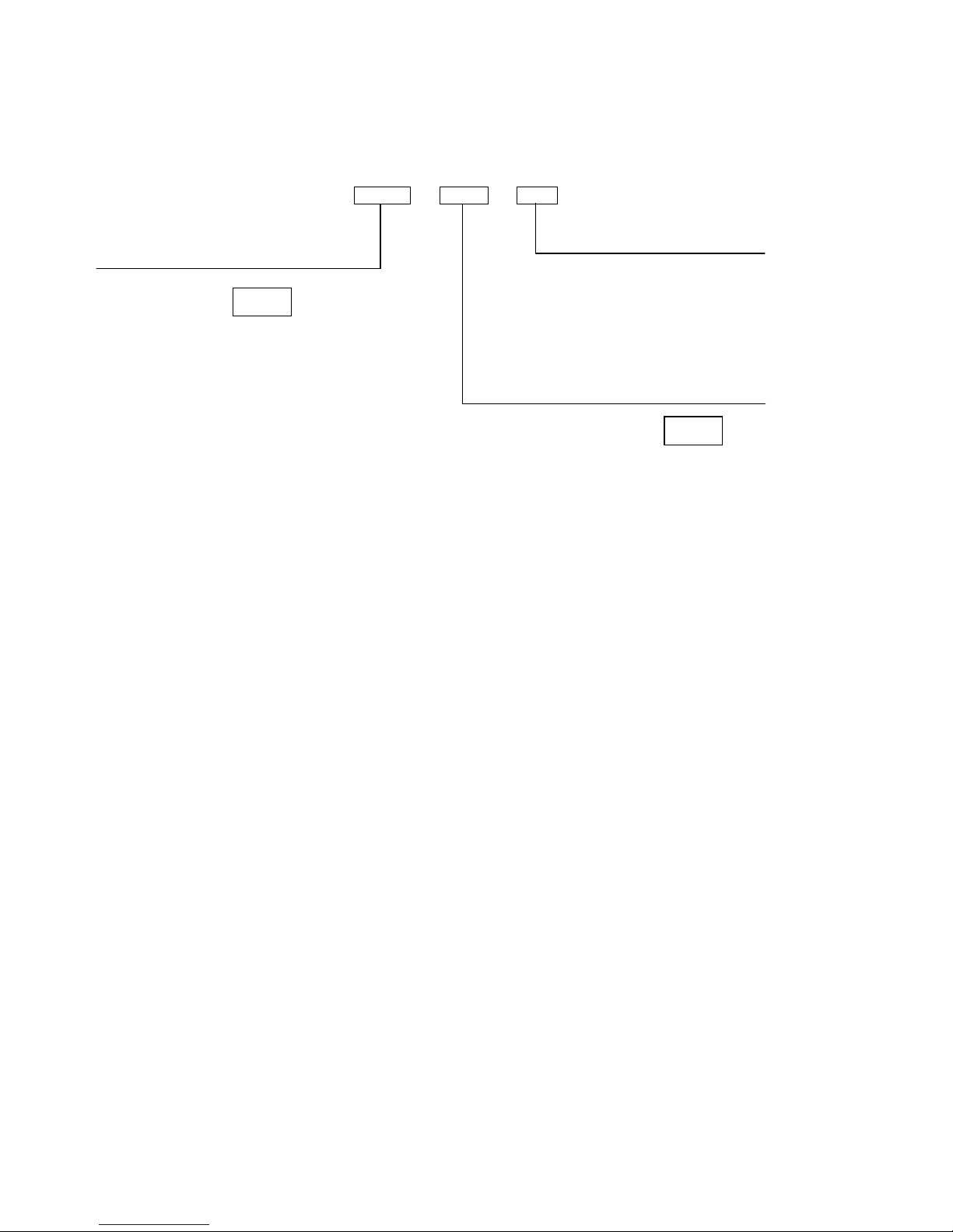
0331 - 001 - 01
At the time of this document production, there have been no revisions to the module hardware.
Product type
Variant
Hardware revision
Revision 1
001
DSE 331 Auto
Transfer Switch
(ATS) Module
331
Page 7

Specifications
7
3.1 POWER SUPPLY REQUIREMENTS
Minimum supply voltage 8V continuous, 5V for up to one minute.
Cranking dropouts
Able to survive 0V for 50mS providing the supply was at least
10V before the dropout and recovers to 5V afterwards.
Maximum supply voltage 35V continuous (60V protection for one minute)
Reverse polarity protection -35V continuous
Maximum operating current
Auto mode will all inputs active and
all LEDs illuminated
168mA at 12V, 80mA at 24V
Maximum standby current
(Stop mode with no active inputs)
39mA at 12V, 20mA at 24V
Plant supply instrumentation display
Range 0V-35V DC (note Maximum continuous operating voltage of 35V
DC)
Resolution 0.1V
Accuracy 1% of full scale
3.2 TERMINAL SPECIFICATION
Connection type Screw terminal, rising clamp, no internal spring
Min cable size 0.5mm² (AWG 24)
Max cable size 2.5mm² (AWG 10)
3.3 S1/S2 VOLTAGE / FREQUENCY SENSING
Measurement type True RMS conversion
Sample Rate 5KHz or better
Harmonics Up to 11th or better
Input Impedance
300K Ω ph-N
Phase to Neutral 15V
(minimum required for sensing frequency
)
to 333V AC
(absolute maximum)
Suitable for 110V to 277V nominal
(±20% for under/overvoltage detection)
Phase to Phase 25V
(minimum required for sensing frequency
)
to 576V AC
(absolute maximum)
Suitable for 190V ph-ph to 479V ph-ph nominal
(±20% for under/overvoltage detection)
Common mode offset
from Earth
100V AC (max)
Resolution 1V AC phase to neutral
2V AC phase to phase
Accuracy ±1% of full scale phase to neutral
±2% of full scale phase to phase
Minimum frequency 3.5Hz
Maximum frequency 75.0Hz
Frequency resolution 0.1Hz
Frequency accuracy ±0.2Hz
Page 8

Specifications
8
3.4 INPUTS
3.4.1 DIGITAL INPUTS
Number 4
Arrangement Contact between input terminal and the module’s plant supply negative terminal
Low level threshold 3.0V minimum
High level threshold 4.1V maximum
Maximum input voltage +60V DC with respect to module’s plant supply negative terminal
Minimum input voltage -2V DC with respect to module’s plant supply negative terminal
Contact wetting current 6mA ±1mA
Open circuit voltage 12V ±1V
3.5 OUTPUTS
3.5.1 CONFIGURABLE NORMALLY OPEN RELAY OUTPUTS A & B
Number 2 (Configurable outputs A & B)
Type Volts free normally open contacts
Rating 8A @ 35VDC
3.5.2 CONFIGURABLE CHANGEOVER RELAY OUTPUTS C & D
Number 2 (Configurable output C)
Type Volts free change over contacts.
Rating 8A @ 35VDC
3.5.3 CONFIGURABLE OUTPUTS E - H
Number 4
Type Fully configurable, DC outputs rated at DC voltage
Rating 8A @ 35VDC
Protection Protected against over current & over temperature. Built in load dump feature.
3.6 COMMUNICATION PORTS
USB Port USB2.0 Device for connection to PC running DSE configuration suite only
Page 9
Specifications
9
3.7 DIMENSIONS AND MOUNTING
3.7.1 DIMENSIONS
180mm x 116mm x 42mm
(7.1” x 4.6” x 1.7”)
3.7.2 PANEL CUTOUT
154mm x 98mm
(6” x 3.9”)
3.7.3 WEIGHT
400g (0.4kg)
3.7.4 FIXING CLIPS
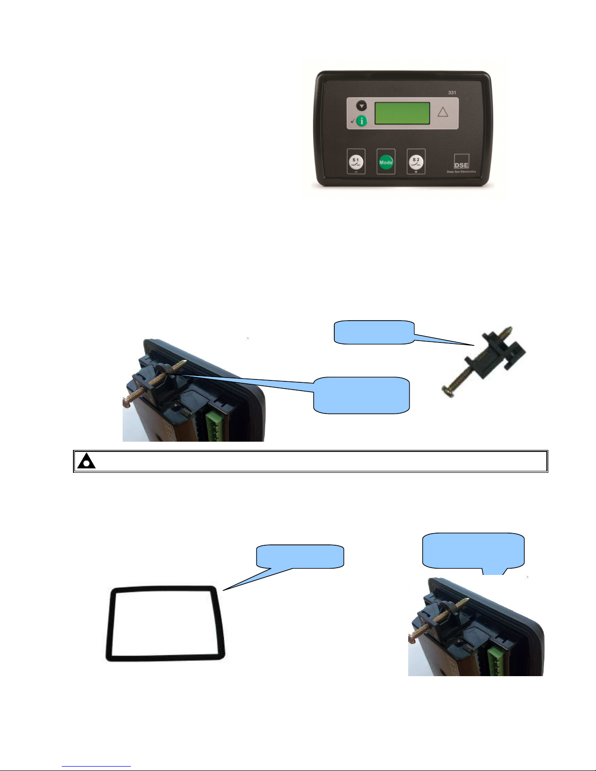
The module is held into the panel fascia using the supplied fixing clips.
• Withdraw the fixing clip screw (turn anticlockwise) until only the pointed end is protruding from the clip.
• Insert the three ‘prongs’ of the fixing clip into the slots in the side of the module case.
• Pull the fixing clip backwards (towards the back of the module) ensuring all three prongs of the clip are
inside their allotted slots.
• Turn the fixing clip screws clockwise until they make contact with the panel fascia.
• Turn the screws a little more to secure the module into the panel fascia. Care should be taken not to over
tighten the fixing clip screws.
NOTE:- In conditions of excessive vibration, mount the panel on suitable anti-vibration mountings.
3.7.5 OPTIONAL SILICON SEALING GASKET
The optional silicon gasket provides improved sealing between the module and the panel fascia.
The gasket is fitted to the module before installation into the panel fascia.
Take care to ensure the gasket is correctly fitted to the module to maintain the integrity of the seal.
Fixing clip fitted to
module
Fixing clip
Gasket fitted to
module
Sealing gasket
Page 10

Specifications
10
3.8 APPLICABLE STANDARDS
BS 4884-1
This document conforms to BS4884-1 1992 Specification for presentation of
essential information.
BS 4884-2 This document conforms to BS4884-2 1993 Guide to content
BS 4884-3 This document conforms to BS4884-3 1993 Guide to presentation
BS EN 60068-2-1
(Minimum temperature)
-30°C (-22°F)
BS EN 60068-2-2
(Maximum temperature)
+70°C (158°F)
BS EN 60950
Safety of information technology equipment, including electrical business equipment
BS EN 61000-6-2
EMC Generic Immunity Standard (Industrial)
BS EN 61000-6-4
EMC Generic Emission Standard (Industrial)
BS EN 60529
(Degrees of protection
provided by enclosures)
IP65 (front of module when installed into the control panel with the optional sealing
gasket)
IP42 (front of module when installed into the control panel WITHOUT being sealed
to the panel)
UL508
NEMA rating
(Approximate)
12 (Front of module when installed into the control panel with the optional sealing
gasket).
2 (Front of module when installed into the control panel WITHOUT being sealed to
the panel)
IEEE C37.2
(Standard Electrical Power
System Device Function
Numbers and Contact
Designations)
Under the scope of IEEE 37.2, function numbers can also be used to represent
functions in microprocessor devices and software programs.
The 331 controller is device number 11L-331 (Multifunction device protecting Line
(generator) – 331 series module).
As the module is configurable by the generator OEM, the functions covered by the
module will vary. Under the module’s factory configuration, the device numbers
included within the module are :
2 – Time delay starting or closing relay
30 – annunciator relay
42 – Running circuit breaker
62 – time delay stopping or opening relay
74– alarm relay
81 – frequency relay
86 – lockout relay
In line with our policy of continual development, Deep Sea Electronics, reserve the right to change specification without notice.
Page 11
Specifications
11
3.9 ENCLOSURE CLASSIFICATIONS
3.9.1
IP CLASSIFICATIONS
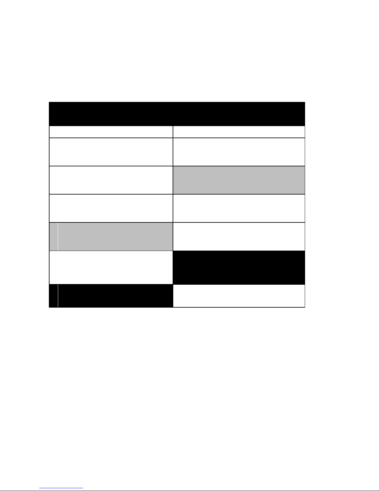
3xx series specification under BS EN 60529 Degrees of protection provided by enclosures
IP65 (Front of module when module is installed into the control panel with the supplied sealing gasket).
IP42 (front of module when module is installed into the control panel WITHOUT being sealed to the panel)
First Digit Second Digit
Protection against contact and ingress of solid objects Protection against ingress of water
0 No protection 0 No protection
1 Protected against ingress solid objects with a diameter
of more than 50 mm. No protection against deliberate
access, e.g. with a hand, but large surfaces of the
body are prevented from approach.
1 Protection against dripping water falling vertically. No
harmful effect must be produced (vertically falling drops).
2 Protected against penetration by solid objects with a
diameter of more than 12 mm. Fingers or similar
objects prevented from approach.
2 Protection against dripping water falling vertically. There
must be no harmful effect when the equipment
(enclosure) is tilted at an angle up to 15° from its normal
position (drops falling at an angle).
3 Protected against ingress of solid objects with a
diameter of more than 2.5 mm. Tools, wires etc. with a
thickness of more than 2.5 mm are prevented from
approach.
3 Protection against water falling at any angle up to 60°
from the vertical. There must be no harmful effect (spray
water).
4 Protected against ingress of solid objects with a
diameter of more than 1 mm. Tools, wires etc. with a
thickness of more than 1 mm are prevented from
approach.
4 Protection against water splashed against the equipment
(enclosure) from any direction. There must be no harmful
effect (splashing water).
5 Protected against harmful dust deposits. Ingress of
dust is not totally prevented but the dust must not
enter in sufficient quantity to interface with satisfactory
operation of the equipment. Complete protection
against contact.
5 Protection against water projected from a nozzle against
the equipment (enclosure) from any direction. There must
be no harmful effect (water jet).
6 Protection against ingress of dust (dust tight).
Complete protection against contact.
6 Protection against heavy seas or powerful water jets.
Water must not enter the equipment (enclosure) in
harmful quantities (splashing over).
Page 12
Specifications
12
3.9.2 NEMA CLASSIFICATIONS
3xx series NEMA Rating (Approximate)
12 (Front of module when module is installed into the control panel with the optional sealing gasket).
2 (front of module when module is installed into the control panel WITHOUT being sealed to the panel)
NOTE: - There is no direct equivalence between IP / NEMA ratings. IP figures shown are approximate
only.
1
IP30
Provides a degree of protection against contact with the enclosure equipment and against a limited amount of falling dirt.
2
IP31
Provides a degree of protection against limited amounts of falling water and dirt.
3
IP64
Provides a degree of protection against windblown dust, rain and sleet; undamaged by the formation of ice on the enclosure.
3R
IP32
Provides a degree of protection against rain and sleet:; undamaged by the formation of ice on the enclosure.
4 (X)
IP66
Provides a degree of protection against splashing water, windblown dust and rain, hose directed water; undamaged by the formation
of ice on the enclosure. (Resist corrosion).
12/12K
IP65
Provides a degree of protection against dust, falling dirt and dripping non corrosive liquids.
13
IP65
Provides a degree of protection against dust and spraying of water, oil and non corrosive coolants.
Page 13
Installation
13
4 INSTALLATION
4.1 TERMINAL DESCRIPTION
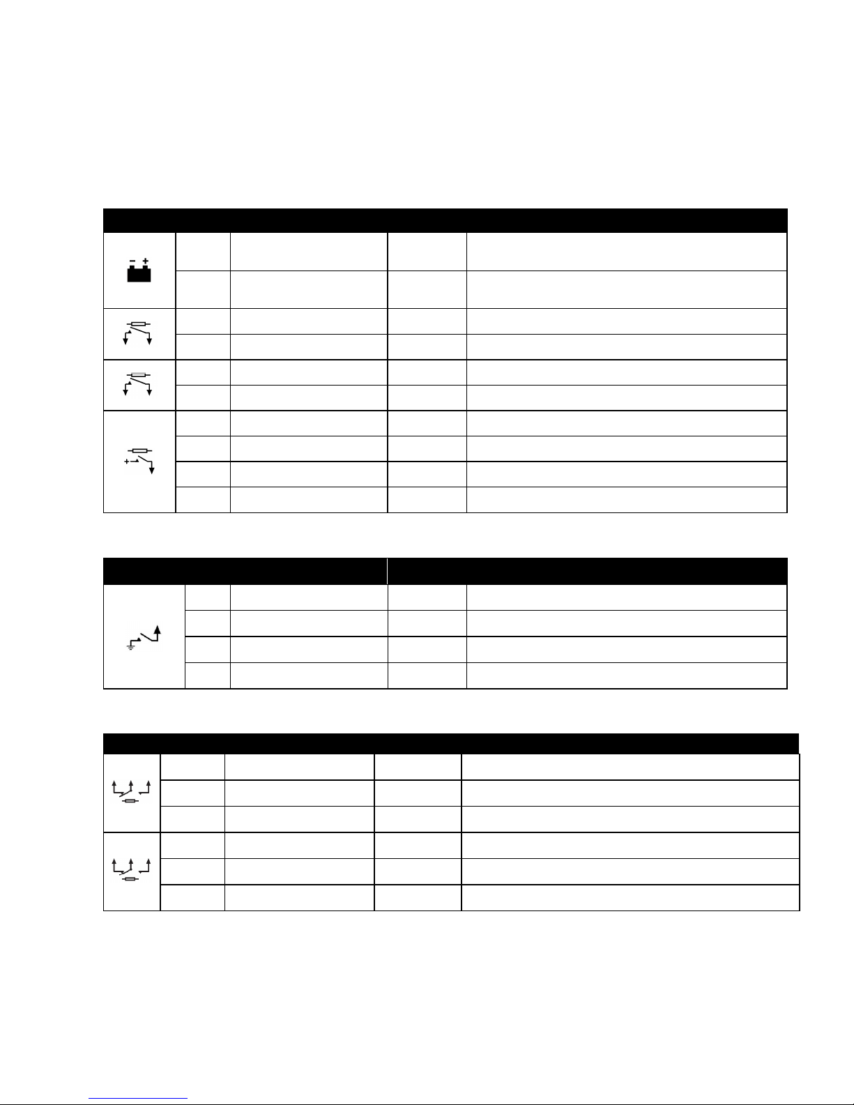
4.1.1 DC SUPPLY & DC OUTPUTS.
PIN No DESCRIPTION CABLE SIZE NOTES
1
DC Plant Supply Input
(Negative)
2.5mm²
AWG 13
2
DC Plant Supply Input
(Positive)
2.5 mm²
AWG 13
(Recommended Maximum Fuse 15A anti-surge)
Supplies the module (2A anti-surge requirement) and all output
relays
3 Output A
1.0mm²
AWG 18
Volts free relay (8A rated)
4 Output A
1.0mm²
AWG 18
Volts free relay (8A rated)
5 Output B
1.0mm²
AWG 18
Volts free relay (8A rated)
6 Output B
1.0mm²
AWG 18
Volts free relay (8A rated)
7 Output E
1.0mm²
AWG 18
Plant Supply Positive from terminal 7. 2 Amp rated.
8 Output F
1.0mm²
AWG 18
Plant Supply Positive from terminal 8. 2 Amp rated.
9 Output G
1.0mm²
AWG 18
Plant Supply Positive from terminal 9. 2 Amp rated.
10 Output H
1.0mm²
AWG 18
Plant Supply Positive from terminal 10 2 Amp rated.
4.1.2 DIGITAL INPUTS.
4.1.3 VOLT FREE OUTPUTS.
PIN No DESCRIPTION CABLE SIZE NOTES
23 Output C
1.0mm²
AWG 18
User configured volt free output (N/O)
24 Output C
1.0mm²
AWG 18
User configured volt free output (Common)
25 Output C
1.0mm²
AWG 18
User configured volt free output (N/C)
26 Output D
1.0mm²
AWG 18
User configured volt free output (N/O)
27 Output D
1.0mm²
AWG 18
User configured volt free output (Common)
28 Output D
1.0mm²
AWG 18
User configured volt free output (N/C)
PIN
No
DESCRIPTION CABLE SIZE NOTES
11 Input A
1.0mm²
AWG 18
Configurable input. Connects to plant supply negative
12 Input B
1.0mm²
AWG 18
Configurable input. Connects to plant supply negative
13 Input C
1.0mm²
AWG 18
Configurable input. Connects to plant supply negative
14 Input D
1.0mm²
AWG 18
Configurable input. Connects to plant supply negative
Page 14
Installation
14
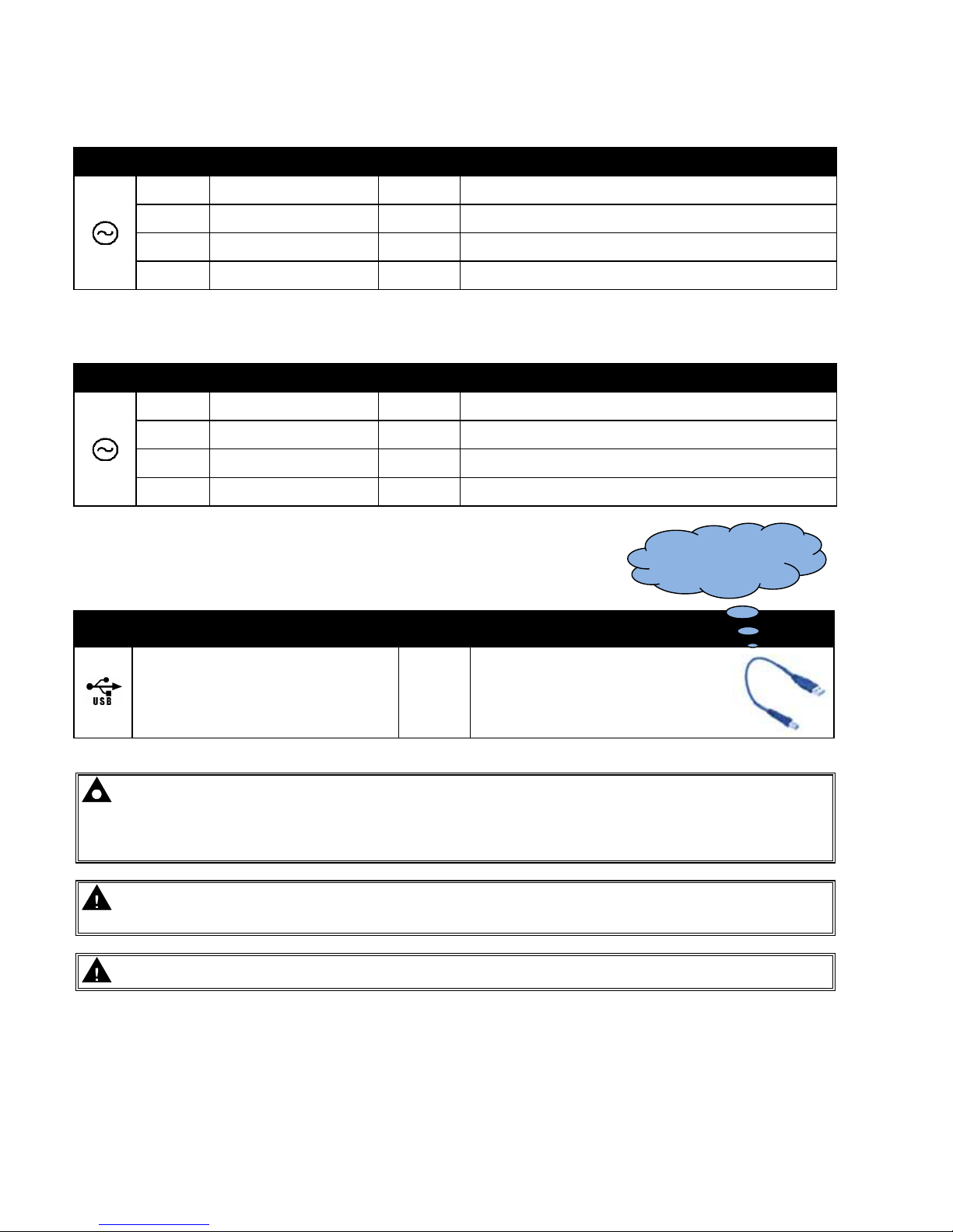
4.1.4 S1 SENSING
PIN No DESCRIPTION
CABLE
SIZE
NOTES
19 S1 L1 (R) voltage monitoring
1.0mm²
AWG 18
Connect to S1 L1 (R) output (AC)
(Recommend 2A fuse)
20 S1 L2 (S) voltage monitoring
1.0mm²
AWG 18
Connect to S1 L2 (S) output (AC)
(Recommend 2A fuse)
21 S1 31 (T) voltage monitoring
1.0mm²
AWG 18
Connect to S1 L3 (T) output (AC)
(Recommend 2A fuse)
22 S1 Neutral (N) input
1.0mm²
AWG 18
Connect to S1 Neutral terminal (AC)
4.1.5 S2 SENSING
PIN No DESCRIPTION
CABLE
SIZE
NOTES
15 S2 L1 (R) voltage monitoring
1.0mm²
AWG 18
Connect to S2 L1 (R) output (AC)
(Recommend 2A fuse)
16 S2 L2 (S) voltage monitoring
1.0mm²
AWG 18
Connect to S2 L2 (S) output (AC)
(Recommend 2A fuse)
17 S2 31 (T) voltage monitoring
1.0mm²
AWG 18
Connect to S2 L3 (T) output (AC)
(Recommend 2A fuse)
18 S2 Neutral (N) input
1.0mm²
AWG 18
Connect to S2 Neutral terminal (AC)
4.1.6 PC CONFIGURATION INTERFACE CONNECTOR
DESCRIPTION CABLE
SIZE
NOTES
Socket for connection to PC with DSE
Configuration Suite PC software.
0.5mm²
AWG 20
This is a standard USB type A to
type B cable.
NOTE:- The USB connection cable between the PC and the DSE331 module must not be extended
beyond 5m (5yds). For distances over 5m, it is possible to use a third party USB extender. Typically, they
extend USB up to 50m (yds). The supply and support of this type of equipment is outside the scope of
Deep Sea Electronics PLC.
CAUTION!: Care must be taken not to overload the PCs USB system by connecting more than the
recommended number of USB devices to the PC. For further information, consult your PC supplier.
CAUTION!: This socket must not be used for any other purpose.
This configuration cable is
the same as normally used
between a PC and a USB
printer.
Page 15
Installation
15
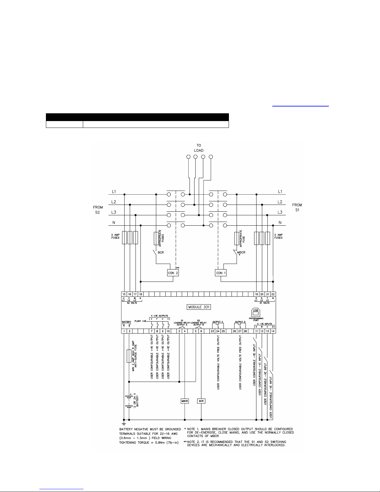
4.2 TYPICAL WIRING DIAGRAM
As every system has different requirements, these diagrams show only a TYPICAL system and do not intend to
show a complete system.
Genset manufacturers and panel builders may use these diagrams as a starting point, however you are referred to
the completed system diagram provided by your system manufacturer for complete wiring detail.
Further wiring suggestions are available in the following DSE publication, available at www.deepseaplc.com.
DSE PART DESCRIPTION
056-022 Breaker Control (Training guide)
Page 16
Description of Controls
16
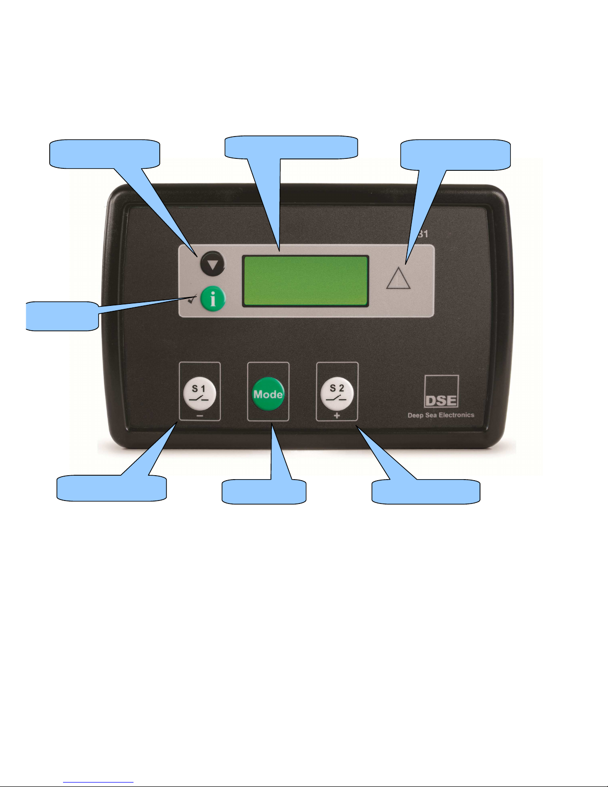
5 DESCRIPTION OF CONTROLS
The following section details the function and meaning of the various controls on the module.
Display Scroll button
Common Alarm
Indicator
S1 breaker control
Main status display
Select Mode
S2 breaker control
Info button
Page 17
Description of Controls
17
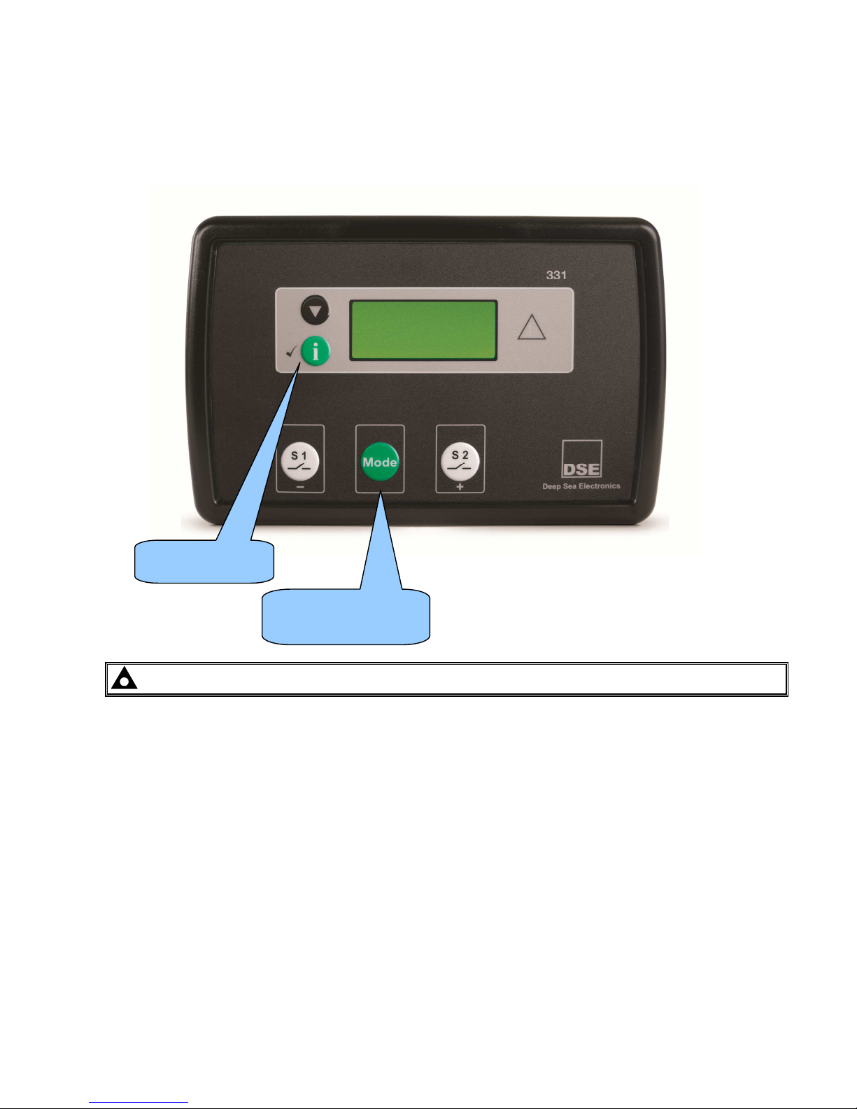
QUICKSTART GUIDE
This section provides a quick start guide to the module’s operation.
5.1.1 MODE SELECTION OPERATION
NOTE:- For further details, see the section entitled ‘MODE SELECTION’ elsewhere in this manual.
Press button until
preferred mode is
Press button to
confirm selected
Page 18
Description of Controls
18
5.2 GRAPHICAL DISPLAY
- 4- line, 64 x 132 small Graphic Display with LED Backlight
- Icon and numeric display. Switch to select ‘Icon’ or ‘English’ display
- Software controlled contrast
- Mimic of Text insert / 4x indicators via LCD
5.2.1 DISPLAY PAGES
It is possible to scroll to display the different pages of information by repeatedly operating the scroll button
Once selected the page will remain on the LCD display until the user selects a different page or after an extended
period of inactivity, the module will revert to the status display.
When scrolling manually, the display will automatically return to the Status page if no buttons are pressed for the
duration of the configurable LCD Page Timer.
If an alarm becomes active while viewing the status page, the display shows the Alarms page to draw the
operator’s attention to the alarm condition.
At power up, the display will show the software version, and then display the default display screen, which will
display Mains instrumentation.
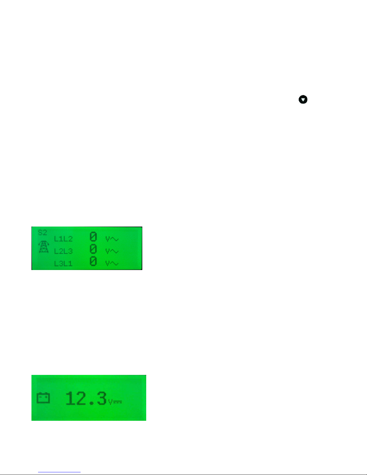
5.2.1.1 STATUS
Displays voltage operational status information
Example :
5.2.1.2 INSTRUMENTATION
The instrumentation page contains the following information
S1 Voltage L-N
S1 Voltage L-L
S1 Frequency
S2 Voltage L-N
S2 Voltage L-L
S2 Frequency
Battery Voltage
Scheduler
Example::
Page 19
Description of Controls
19
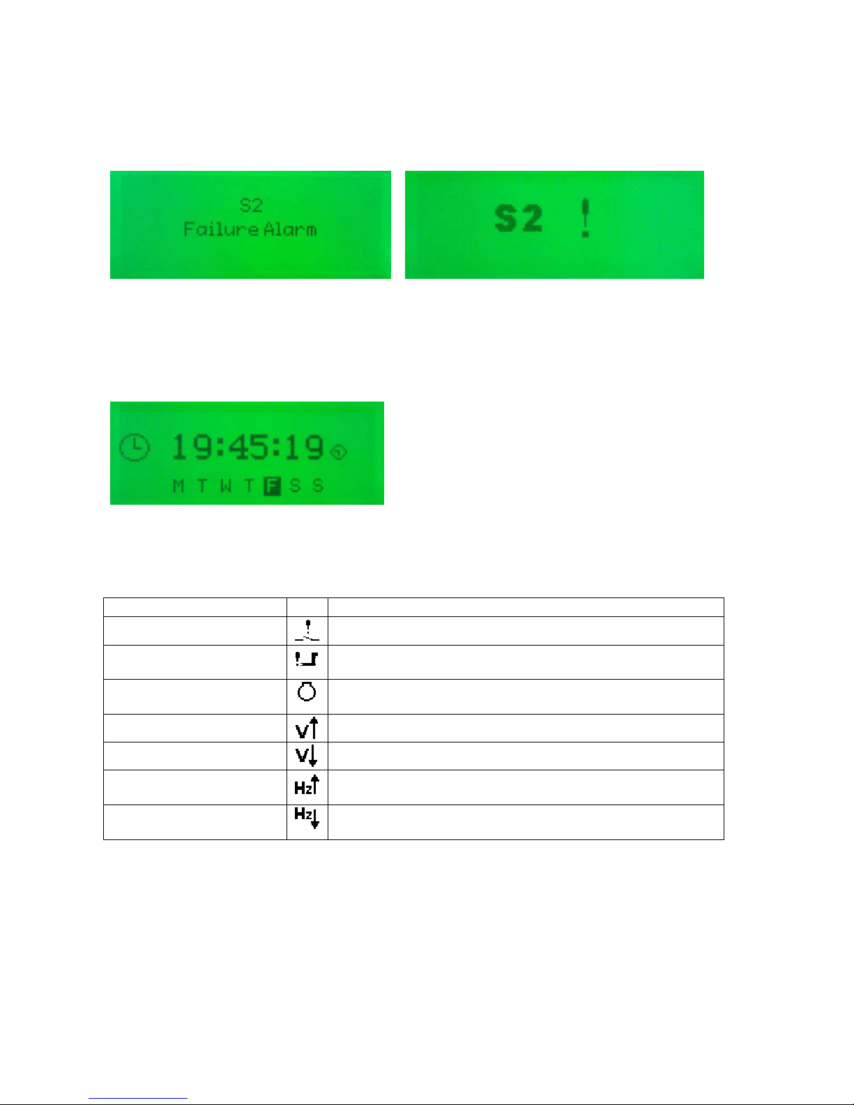
5.2.1.3 ALARMS
Lists any current alarms
Example (English) (Icon)
5.2.1.4 SCHEDULER.
Shows the settings of the exercise scheduler
Example:
5.2.2 ALARM ICONS
In instances where more than one alarm is present the icon area will transition between icons to display all active
alarm conditions. For information alarm conditions see section
Alarm Icon Reason
Switch fail alarm
The Switching device has failed to operate.
Failed to start
The engine has not fired after the preset number of start
attempts.
Failed to stop
The module has detected a condition that indicates that the
engine is running when it has been instructed to stop.
Over Voltage
S1 or S2 voltage has risen above the pre-set pre-alarm setting.
Under voltage
S1 or S2 voltage has fallen below the pre-set pre-alarm setting.
Over frequency
S1 or S2 frequency has risen above the pre-set pre-alarm
setting.
Under frequency
S1 or S2 frequency has fallen below the pre-set pre-alarm
setting.
Page 20
Description of Controls
20
5.3 CONTROLS
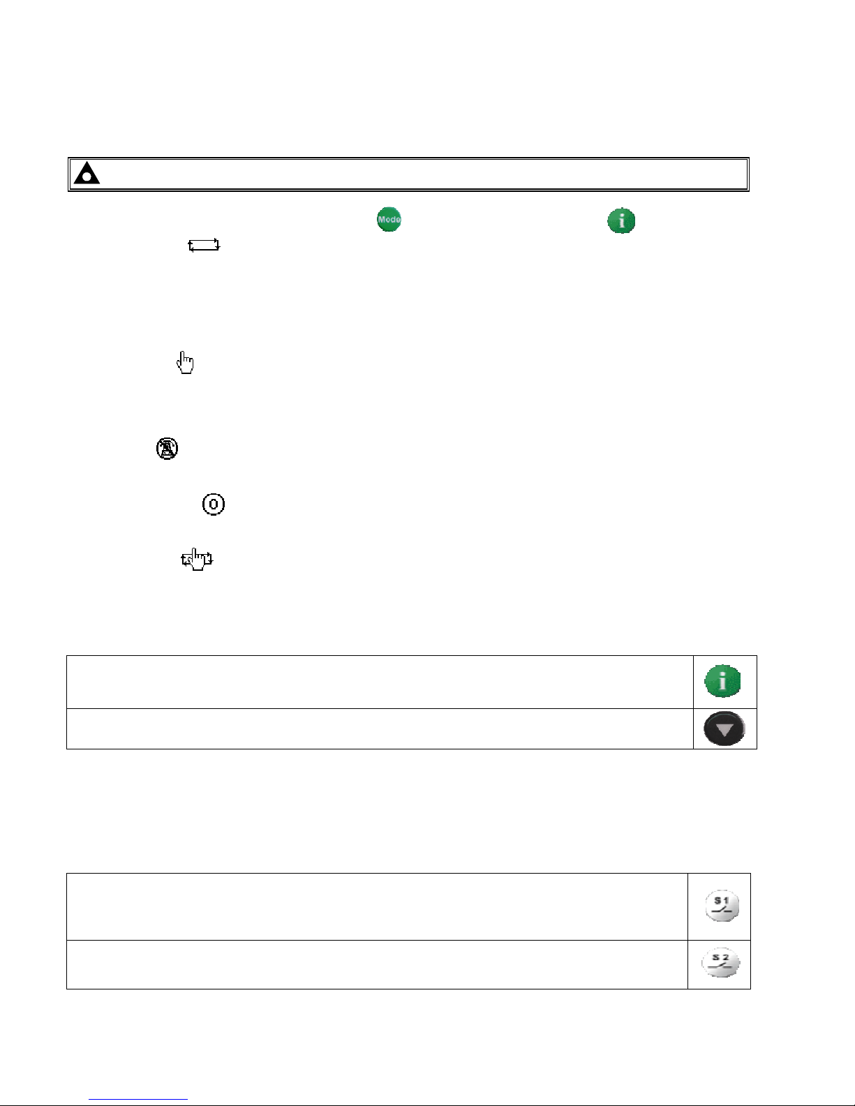
5.3.1 MODE SELECTION
NOTE:- Icons only apply when display mode in the software programme is set to `icons`
5.3.2 DISPLAY
This button changes between the various pages About, Status, Instrumentation, Alarms, Event Log, LCD
Indicators
This buttons scrolls through the items in the currently displayed page.
5.3.3 LOAD SWITCHING CONTROL
Two fascia mounted buttons are provided for load switching operation when in manual mode. These buttons are
enabled/disabled in the modules PC configuration Suite so refer to your configuration file to ensure the
configuration has enabled the buttons.
Pressing this button when the S1 is on load will open the S1 load switch.
Pressing this button when S2 is on load and S1 is healthy, will open S2 load switch, wait for the duration
of the transfer delay, then close the S1 load switch.
Pressing this button when S2 is on load will open the S2 load switch.
Pressing this button when the S1 is on load and S2 is available, will open the S1 load switch, wait for
the duration of the transfer delay, then close S2 load switch.
This button selects the preferred mode of operation. to complete the selection press the button.
Automatic mode. This mode allows the module to control the function of the load switching completely
automatically. The module will monitor the remote start input and mains supply status and once a start request is
made, the set will be placed on load.
Upon removal of the starting signal (or S1supply returns), the module will automatically transfer the load from the
generator to the mains and remove the genset starting instruction.
Manual mode. This mode allows manual control of the ATS functions. Once in this mode the module will
send a start request to the generator.
Breakers can be opened and close using the transfer buttons detailed below.
Test mode. Once in Test mode the module will send a start request to the generator and place the set on
load or off load depending what is set in the software. The set will remain on load or off load when in this mode.
Start inhibit mode.
This mode is used to provide an over-ride function to prevent the controller from starting the
generator in the event of a remote start/S1 out of limits condition occurring.
Prohibit return.
This mode is used to prevent the module from loading S1 even though S1 has returned.
Page 21

Operation
21
6 OPERATION
6.1 AUTOMATIC MODE OF OPERATION
NOTE:- If a digital input configured to external panel lock is active, changing module modes will not
be possible. Viewing the instruments is NOT affected by panel lock.
Activate auto mode by pressing the mode button until Auto is selected and then press the button to
confirm.
Auto mode will allow the transfer system to operate fully automatically, switching between S1 and S2 as required
with no user intervention.
6.1.1 WAITING IN AUTO MODE
If a starting request is made and there is no input present for Auto Start Inhibit, the starting sequence will begin.
Starting requests can be from the following sources :
• S1 failure
• Activation of an auxiliary input that has been configured to remote start
• Activation of the inbuilt exercise scheduler.
6.1.2 STARTING SEQUENCE
To allow for ‘false’ start requests, the start delay timer begins.
Should all start requests be removed during the start delay timer, the unit will return to a stand-by state.
When S2 is configured for a generator If a start request is still present at the end of the start delay timer the Start
and Run S2 output will be energised. After the generator has started, it will enter the warming up timer.
If S2 fails to become available before the S2 Fail Delay timer expires the module will alarm. This is indicated on
the LCD display but the starting signal remains active.
6.1.3 S1 / S2 ON LOAD
Once S2 is measured as being within limits S1 is removed from the load, and after the transfer timer has expired,
S2 is placed on load.
If all start requests are removed and there is no input present for Auto Restore Inhibit, the stopping sequence will
begin.
6.1.4 STOPPING SEQUENCE
The return delay timer operates to ensure that the starting request has been permanently removed and isn’t just a
short term removal.
After the return delay timer, the generator load switch is opened, then after the transfer timers, the mains is placed
back on load.
Should another start request be made during the cooling down period, the generator will be placed on load.
The cooling timer allows the set to run off load and cool sufficiently before being stopped. This is particularly
important where turbo chargers are fitted to the engine.
After the cooling timer has expired, the set is stopped.
Page 22
Operation
22
6.2 MANUAL OPERATION
NOTE:- If a digital input configured to panel lock is active, changing module modes will not be
possible. Viewing the instruments and event logs is NOT affected by panel lock.
Manual mode allows the operator to change the state of the load switching devices.
6.2.1 STARTING SEQUENCE
NOTE:- There is no start delay in this mode of operation.
The start request is sent to the generator via a digital output configured to Start and Run S2.
If S2 fails to become available before the S2 failure timer expires. This is indicated on the LCD display, but the
starting signal remains active.
6.2.2 S1 OFF LOAD
The generator will continue run OFF LOAD in this mode unless :
• S1 supply fails
• An input is given for Auxiliary S1 fail
• An input is given for Transfer to S2
• The fascia mounted transfer buttons are pressed (when configured)
6.2.3 S2 ON LOAD
Once on load, the generator will remain on load unless:
• An input is given for Transfer to S1
• The fascia mounted transfer buttons are pressed (when configured)
• The module mode is changed to AUTO mode. The system may then transfer back to mains supply
automatically if conditions are suitable.
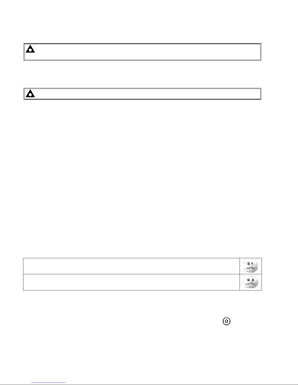
6.2.4 TRANSFER BUTTONS OPERATION
Two fascia mounted buttons are provided for load switching operation when in manual mode. These buttons are
enabled/disabled in the modules PC configuration Suite so refer to your configuration file to ensure the
configuration has enabled the buttons.
Pressing this button when S1 is on load will open S1 load switch.
Pressing this button when S2 is on load and S1 is healhty, will open S2 load switch, wait for the duration
of the transfer delay, then close the S1 load switch.
Pressing this button when S2 is on load will open S2 load switch.
Pressing this button when S1 is on load and S2 is available, will open S1 load switch, wait for the
duration of the transfer delay, then close S2 load switch.
6.2.5 STOPPING SEQUENCE
The set will not be stopped in this mode of operation.
To begin the stopping sequence, the module should be placed in the AUTO or START INHIBIT mode.
Page 23
Operation
23
6.3 TEST ON OPERATION
NOTE:- If a digital input configured to panel lock is active, changing module modes will not be
possible. Viewing the instruments and event logs is NOT affected by panel lock.
Test mode allows the operator to start and stop the set manually, and if required change the state of the load
switching devices. Test on load and Test off load is selectable in the software.
6.3.1 STARTING SEQUENCE
NOTE:- There is no start delay in this mode of operation.
The start request is sent to the generator via a digital output configured to Start and Run S2.
If S2 fails to become available before S2 fail delay timer expires. This is indicated on the LCD display, but the
starting signal remains active.
6.3.2 S2 ON LOAD
S2 will continue run ON LOAD in this mode unless :
• S2 supply fails – S2 supply is placed back on load if available.
• An input is given for Open/Close S1
6.3.3 STOPPING SEQUENCE
The set will not be stopped in this mode of operation.
To begin the stopping sequence, the module should be placed in the AUTO or START INHIBIT mode.
Page 24
Operation
24
6.4 LOAD SWITCHING CONTROL
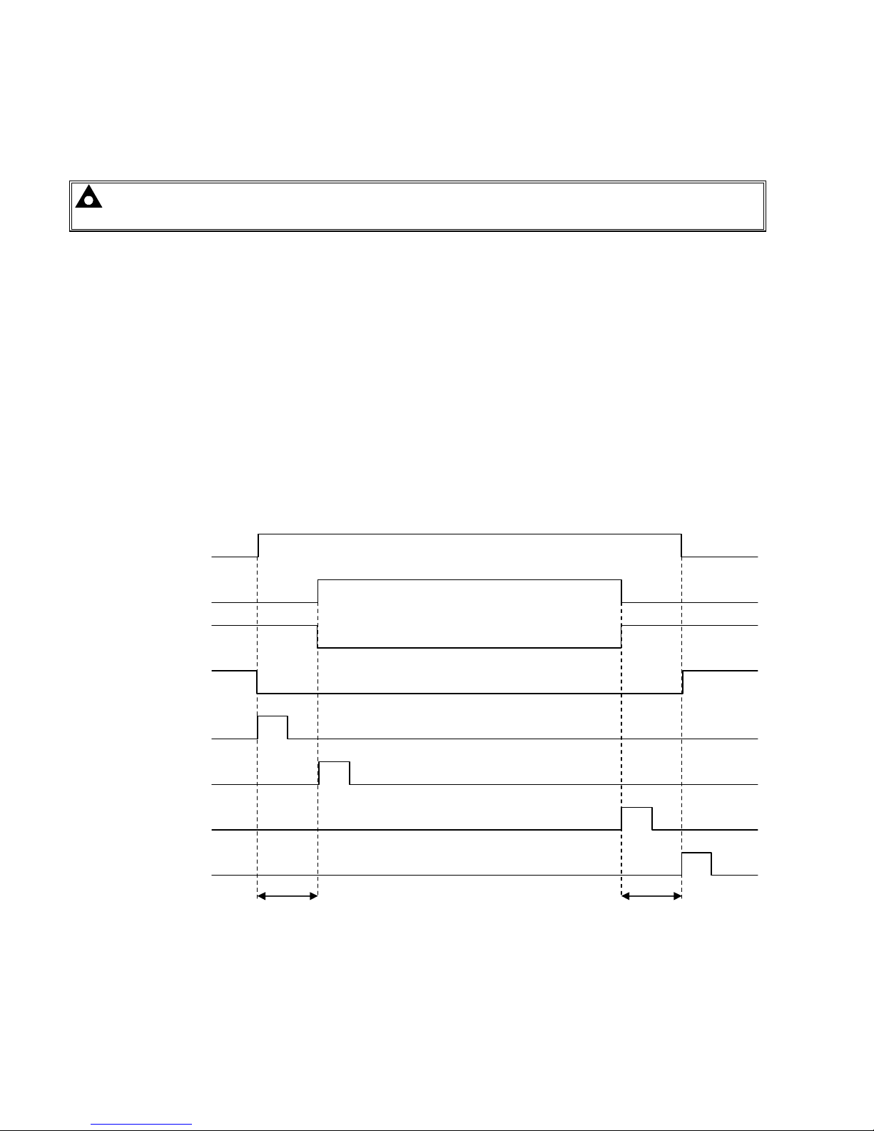
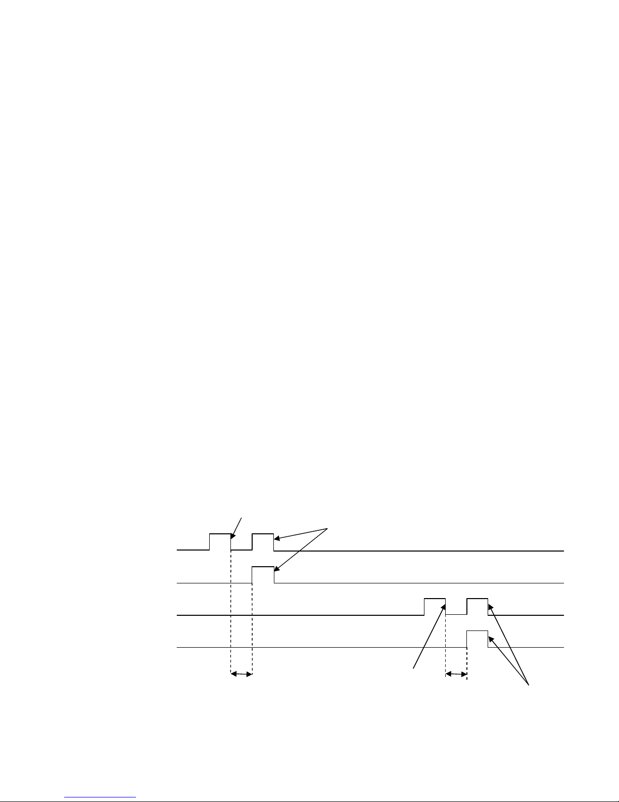
The following timing diagrams detail the differences between the load switching control options.
6.4.1 BREAKER SCHEME A
NOTE : S2 Closed Auxiliary and S1 Closed Auxiliary inputs do not affect the operation of the load
switching in Breaker Scheme A
6.4.2 S1 / S2 LOAD INHIBIT
Activation of an input configured to S1 load inhibit or S2 load inhibit inputs cause the corresponding breaker to be
opened immediately. No other change in function will occur.
When the input is deactivated the breaker is closed again if appropriate.
6.4.3 LOAD SHEDDING
If an input configured to Load Shed is activated, outputs set to Open S1 and Open S2 will energise, and inputs
configured to Open/CloseS1 and Open/CloseS2 will de-energise. Open S1 Ouput Pulse and Open S1 Ouput Pulse
will only energise if the corresponding supply was on load before application of the Load Shed input.
When the Load Shed input is deactivated, the load will be transferred back to the supply that was disconnected
before application of the input.
6.4.4 TIMING DIAGRAM
Open S1
Close S2
Close S1
Open S2
Open S1 Pulse
Close S2 Pulse
Close S1 Pulse
Open S2 Pulse
Transfer time Transfer Time
Page 25
Operation
25
6.4.5 BREAKER SCHEME B
Breaker Scheme B is intended only for use with certain designs of transfer switch. If you are using contactors, you
MUST select Breaker Scheme A.
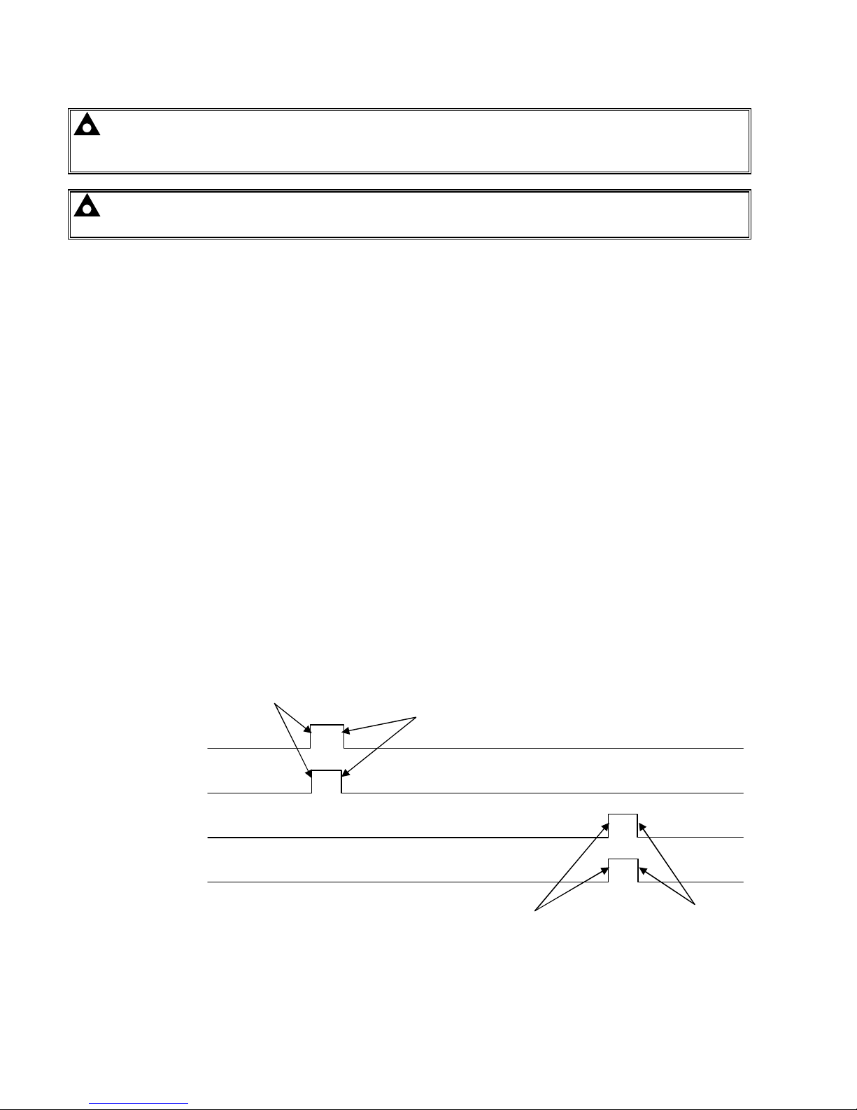
6.4.5.1 CHECK SYNCHRONISING IS DISABLED
6.4.5.1.1 TRANSFERRING TO S2
To open S2 breaker the Open S1 output energises, it then de-energises when the S1 Closed Auxiliary indicates it
has successfully opened, or after 1s whichever occurs first.
When the ‘S1 Closed Auxiliary’ indicates the mains breaker has opened, the transfer timer begins.
When the transfer timer expires, the module attempts to close S2 breaker by energising the Open S1 and Close
S2 outputs simultaneously, it then de-energises these outputs when the S2 Closed Auxiliary input indicates it has
successfully closed, or after 1s whichever occurs first.
6.4.5.1.2 TRANSFERRING TO S1
To open S1 breaker the Open S2 output energises, it then de-energises when the S2 Closed Auxiliary indicates it
has successfully opened, or after 1s whichever occurs first.
When the ‘S2 Closed Auxiliary’ indicates S2 breaker has opened, the transfer timer begins.
When the transfer timer expires, the module attempts to close S1 breaker by energising the Open S2 and Close
S2 outputs simultaneously, it then de-energises these outputs when S1 Closed Auxiliary input indicates it has
successfully closed, or after 1s whichever occurs first
6.4.5.1.3 LOAD SHED INPUT
When the Load Shed input is activated while the generator is closed the Open S2 output energises, it then deenergises when the S2 Closed Auxiliary input indicates that it has successfully opened, or after 1s whichever
occurs first.
When the Load Shed input is activated while the mains is closed the Open S1 output energises, it then deenergises when the S1 Closed Auxiliary input indicates that it has successfully opened, or after 1s whichever
occurs first.
When the Load shed input is de-energised the load will be returned to the supply that was disconnected, providing
that supply is healthy.
6.4.5.1.4 TIMING DIAGRAM
Open S1
Close S2
Close S1
Open S2
Non-Sync Transfer Time Non-Sync Transfer
S2 has closed
S1 has closed
S1 has opened
S2 has opened
Page 26
Operation
26
6.4.5.2 CHECK SYNCHRONISING IS ENABLED
NOTE : The module waits indefinitely for synchronisation unless the ‘Return to programmed
transition’ function is active in which case after 2 minutes it performs a non-sync transfer as described in
the previous section.
NOTE : The transfer time is ignored during a check-sync but is used if the transfer fails and it
performs a non-sync transfer.
6.4.5.2.1 TRANSFER TO S2
When the module is about to transfer from S1 to S2 it activates the check sync function.
When the S1 and S2 are within the phase and frequency window the module energises the Open S1 and Close S2
outputs simultaneously. These outputs are de-energised when the S2 Closed Auxiliary input indicates it has
successfully closed, or after 1s whichever occurs first.
6.4.5.2.2 TRANSFER TO S1
When the module is about to transfer from S2 to S1 it activates the check sync function.
When S1 and S1 are within the phase and frequency window the module energises the Open S2 and Close S1
outputs simultaneously. These outputs are de-energised when the S2 Closed Auxiliary input indicates it has
successfully closed, or after 1s whichever occurs first.
6.4.5.2.3 LOAD SHED INPUT
When the Load Shed input is activated while the S2 is closed the Open S2 output energises, it then de-energises
when the S2 Closed Auxiliary input indicates that it has successfully opened, or after 1s whichever occurs first.
When the Load Shed input is activated while the mains is closed the Open S1 output energises, it then deenergises when the S1 Closed Auxiliary input indicates that it has successfully opened, or after 1s whichever
occurs first.
When the Load shed input is de-energised the load will be returned to the supply that was disconnected, providing
that supply is healthy.
6.4.5.2.4 TIMING DIAGRAM
Open S1
Close S2
Close S1
Open S2
S2 has closed
S1 has closed
In Sync
In Sync
Page 27

Protections
27
7 PROTECTIONS
7.1 S2
The 331 ATS module monitors the S2 supply to ensure that it remains within configured levels. If the S2 supply
fails, it is taken off load and the start/run signal is be removed.
S2 failure
S2 has not become available after the period of the S2 Failure timer has expired.
S2 Under Voltage shutdown
The S2 supply is below the configured under voltage trip level
S2 Under Frequency shutdown
The S2 supply is below the configured under frequency trip level
Failed to reach loading voltage
S2 is running and within under / over voltage trip points, but has failed to reach the configured Loading Voltage,
hence it is unfit to take load.
Failed to reach loading frequency
S2 is running and within under / over frequency trip points, but has failed to reach the configured Loading
Frequency, hence it is unfit to take load.
7.2 S1
S1 alarms signal that the mains supply is out of limits. In AUTO mode, the generator is called to start (if not
already running) and will be placed on load when available.
If the S1 supply fails while the S2 is running in MANUAL mode, the 331 ATS module transfers load to S2 supply.
Should an input configured to Simulate S1 Available be active, the mains failure detection is inhibited.
S1 failure
Combined message to indicate the failure of the mains supply or activation of an input configured to Auxiliary S1
Failure.
S1 Under Frequency trip
The S1 supply is below the configured Under Frequency trip level.
S1 Under Voltage trip
The S1 supply is below the configured Under Voltage trip level.
S1 Over Frequency trip
The S1 supply is above the configured Over Frequency trip level.
S1 Over Voltage trip
The S1 supply is above the configured Over Voltage trip level.
7.3 PLANT BATTERY
Plant battery alarms are Warning alarms only. The module displays the fault but no further action is taken.
Under Voltage warning
The battery supply is below the configured Under Voltage warning level.
Under Voltage warning
The battery supply is above the configured Over Voltage warning level.
Page 28
Front Panel Configuration
28
8 FRONT PANEL CONFIGURATION
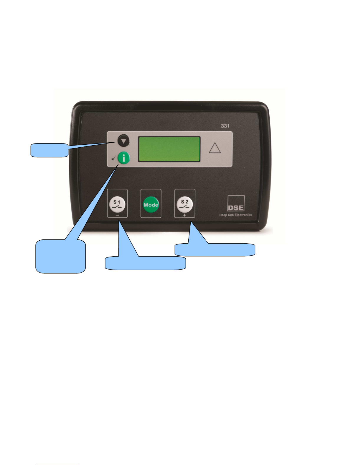
This configuration mode allows the operator limited customising of the way the module operates.
Use the module’s navigation buttons to traverse the menu and make value changes to the parameters:
Increase value / next item
Edit /Accept
value.
Press and hold
to exit editor.
Decrease value / next item
Next page
Page 29
Front Panel Configuration
29
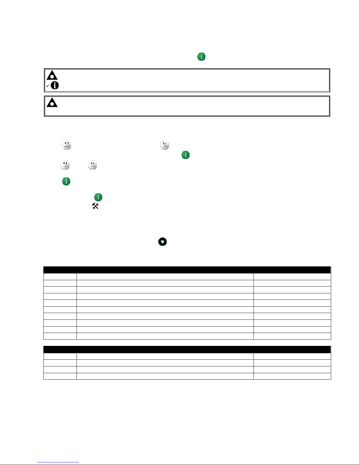
8.1 ACCESSING THE FRONT PANEL EDITOR (FPE)
To enter the ‘configuration mode’ press Press and hold the button
NOTE:- To exit the front panel configuration editor and activate your changes, press and hold the
button. Ensure you have saved any changes you have made by pressing the button first.
NOTE:- When the editor is visible, it is automatically exited after 5 minutes of inactivity to ensure
security.
8.1.1 EDITING A PARAMETER
Press (+) to select the next parameter or (-) to select the previous parameter
When viewing the parameter to be changed, press the button. The value begins to flash.
Press (+) or (-) to adjust the value to the required setting.
Press the save the current value, the value ceases
flashing.
Press and hold the button to exit the editor, the
configuration icon will be removed from the display.
:
8.2 ADJUSTABLE PARAMETERS (CONFIGURATION EDITOR)
When viewing the configuration editor, Press to select the required ‘page’ as listed below.
Front Panel Configuration Editor (Factory default settings are shown in bold italicised text)
CONFIGURATION PARAMETERS – MODULE (Page 1)
101 Contrast 000 (%)
102 Display mode Icon only (1), English (0)n
103 S1 Option Generator (1), Mains (0)
104 S1 Summary screen phase display 1-3
105 S2 Option Generator (1), Mains (0)
106 S2 Summary screen phase display 1-3
107 Lamp test at power up On (1), Off (0)
108 Power up in auto On (1), Off (0)
109 Enable transfer by buttons On (1), Off (0)
110 Test mode On Load (1), Off Load (0)
CONFIGURATION PARAMETERS – APPLICATION (Page 2)
201 Breaker Type Scheme B (1), Scheme A(0)
202 Check Sync On (1), Off (0)
203 Return to Programmed Transition On (1), Off (0)
204 Display mode Icon only (1), English (0)
Page 30

Front Panel Configuration
30
CONFIGURATION PARAMETERS – INPUTS (Page 3)
301 Digital Input A Source 0 (Input Source List)
302 Digital Input A Polarity 0 (Input Polarity List)
303 Digital Input B Source 0 (Input Source List)
304 Digital Input B Polarity 0 (Input Polarity List)
305 Digital Input C Source 0 (Input Source List)
306 Digital Input C Polarity 0 (Input Polarity List)
307 Digital Input D Source 0 (Input Source List)
308 Digital Input D Polarity 0 (Input Polarity List)
CONFIGURATION PARAMETERS – OUTPUTS (Page 4)
401 Digital Output A Source 0 (Output Source List)
402 Digital Output A Polarity 0 (Output Source Polarity)
403 Digital Output B Source 0 (Output Source List)
404 Digital Output B Polarity 0 (Output Source Polarity)
405 Digital Output C Source 0 (Output Source List)
406 Digital Output C Polarity 0 (Output Source Polarity)
407 Digital Output D Source 0 (Output Source List)
408 Digital Output D Polarity 0 (Output Source Polarity)
409 Digital Output E Source 0 (Output Source List)
410 Digital Output E Polarity 0 (Output Source Polarity)
411 Digital Output F Source 0 (Output Source List)
412 Digital Output F Polarity 0 (Output Source Polarity)
413 Digital Output G Source 0 (Output Source List)
414 Digital Output GPolarity 0 (Output Source Polarity)
415 Digital Output H Source 0 (Output Source List)
416 Digital Output H Polarity 0 (Output Source Polarity)
CONFIGURATION PARAMETERS – TIMERS (Page 5)
501 S1 Transient Delay 509 Breaker trip pulse
502 Start Delay 510 Return delay
503 Warming time 511 Cooling time
504 S2 Fail delay 512 S2 transient delay
505 Elevator Delay 513 Fail to stop enable
506 Non-sync transfer time 514 Fai to stop delay
507 Check sync transfer time 515 LCD Page timer
508 Breaker close pulse 516 LCD Scroll timer
CONFIGURATION PARAMETERS – S1 (Page 6)
601 Immediate S1 dropout On (1), Off (0)
602 AC system 0 (AC System)
603 Under voltage enable On (1), Off (0)
604 Under voltage trip 0 V
605 Under voltage return 0 V
606 Over voltage enable On (1), Off (0)
607 Over voltage return 0 V
608 Over voltage trip 0 V
609 Under frequency enable On (1), Off (0)
610 Under frequency trip 0.0 Hz
611 Under frequency return 0.0 Hz
612 Over frequency enable On (1), Off (0)
613 Over frequency return 0.0 Hz
614 Over frequency trip 0.0 Hz
Page 31

Front Panel Configuration
31
CONFIGURATION PARAMETERS – S2 (Page 7)
701 Immediate S2 dropout On (1), Off (0)
702 Under voltage enable (Generator Option) On (1), Off (0)
703 Under voltage trip (Generator Option) 0 V
704 Loading voltage (Generator Option) 0 V
705 Over voltage enable (Generator Option) On (1), Off (0)
706 Over voltage trip (Generator Option) 0 V
707 Under frequency enable (Generator Option) On (1), Off (0)
708 Under frequency trip (Generator Option) 0.0 Hz
709 Loading frequency (Generator Option) 0.0 Hz
710 Over frequency enable (Generator Option) On (1), Off (0)
711 Over frequency trip (Generator Option) 0.0 Hz
712 Under voltage enable (Mains Option) On (1), Off (0)
713 Under voltage (Mains Option) 0 V
714 Under voltage return (Mains Option) 0 V
715 Over voltage enable (Mains Option) On (1), Off (0)
716 Over voltage return (Mains Option) 0 V
717 Over voltage trip (Mains Option) 0 V
718 Under frequency enable (Mains Option) On (1), Off (0)
719 Under frequency (Mains Option) 0.0 Hz
720 Under frequency return (Mains Option) 0.0 Hz
721 Over frequency enable (Mains Option) On (1), Off (0)
722 Over frequency return (Mains Option) 0.0 Hz
723 Over frequency trip (Mains Option) 0.0 Hz
CONFIGURATION PARAMETERS – PLANT BATTERY (Page 8)
801 Under voltage enable On (1), Off (0)
802 Under voltage 0.0 V
803 Under voltage return 0.0 V
804 Under voltage delay 0.00.00
805 Over voltage enable On (1), Off (0)
806 Over voltage return 0.0 V
807 Over voltage trip 0.0 V
808 Over voltage delay 0.00.00
CONFIGURATION PARAMETERS – SCHEDULER (Page 9)
901 Enable scheduler On (1), Off (0)
902 On or off load On (1), Off (0)
903 Start time 0:00
904 Day 1-7 (Day, 1=Monday)
905 Duration 0:00
CONFIGURATION PARAMETERS – TIME (Page 10)
1001 Time of day 0:00
1002 Day of week 1-7 (Day, 1=Monday)
1003 Start time 0:00
Page 32

Front Panel Configuration
32
Parameters with multiple choices use the following identification tables for the parameter values:
INPUT SOURCE LIST
0 Not used
1 Alarm Reset
2 Alarm Mute
3 Auto Restore Inhibit
4 Auto Start Inhibit
5 Auxiliary S2 Available
6 Auxiliary S1 Fail
7 S2 Load Inhibit
8 S2 Closed Auxiliary
9 Inhibit Scheduled Run
10 Lamp Test
11 Load Shedding
12 S1 Closed Auxiliary
13 S1 Load Inhibit
14 Open / Close S2
15 Open / Close S1
16 Panel Lock
17 Remote Start off-load
18 Remote Start on-load
19 Simulated S1 available
20 Simulated S2 available
INPUT POLARITY LIST INPUT ARMING LIST
Index Action Index Arming
0 Close to Activate 0 Always
1 Open to Activate 1 From Safety On
2 From Starting
OUTPUT POLARITY LIST
3 Never
Index Arming
0 Energise
INPUT ACTION LIST
1 De-energise
Index Action
0 Electrical Trip
AC SYSTEM
1 Shutdown
Index Type
2 Warning
0 3 phase 4 wire
1 Single phase 2 wire
2 3 phase 3 wire
3 2 phase 3 wire (L1-L2)
4 2 phase 3 wire (L1-L3)
5 3 phase 4 wire (Delta)
Page 33

Front Panel Configuration
33
OUTPUT SOURCE LIST
0 Not Used
1 Audible Alarm
2 Battery High Voltage
3 Battery Low Voltage
4 Close S2 Output
5 Close S2 Output Pulse
6 Close S1 Output
7 Close S1 Output Pulse
8 Close to N Output
9 Close to N Output Pulse
10 Common Warning
11 Cooling Down
12 Digital Input A
13 Digital Input B
14 Digital Input C
15 Digital Input D
16 Elevator Control
17 Fail to start
18 Fail to stop
19 Fail to reach loading voltage
20 Fail to reach loading frequency
21 S2 Available
22 S2 Failure Latched
23 S2 Failure Unlatched
24 S2 In Limits
25 S2 Load Inhibited
26 S2 ready
27 S1 Failure unlatched
28 S1 Failure latched
29 S1 High Frequency
30 S1 High Voltage
31 S1 In Limits
32 S1 Load Inhibited
33 S1 Low Frequency
34 S1 Low Voltage
35 Return Delay
36 Open S2 Output
37 Open S2 Output Pulse
38 Open S1 Output
39 Open S1 Output Pulse
40 Scheduled Run
41 Start And Run S2
42 Start Delay
43 Waiting For S2
44 Waiting For Manual Restore
45 Warming Up
Page 34
Maintenance, Spares, Repairs, Servicing, Warranty, Disposal
34
9 MAINTENANCE, SPARES, REPAIR AND SERVICING
The DSE331 Series controller is designed to be Fit and Forget. As such, there are no user serviceable parts within
the controller.
In the case of malfunction, you should contact your original equipment supplier (OEM).
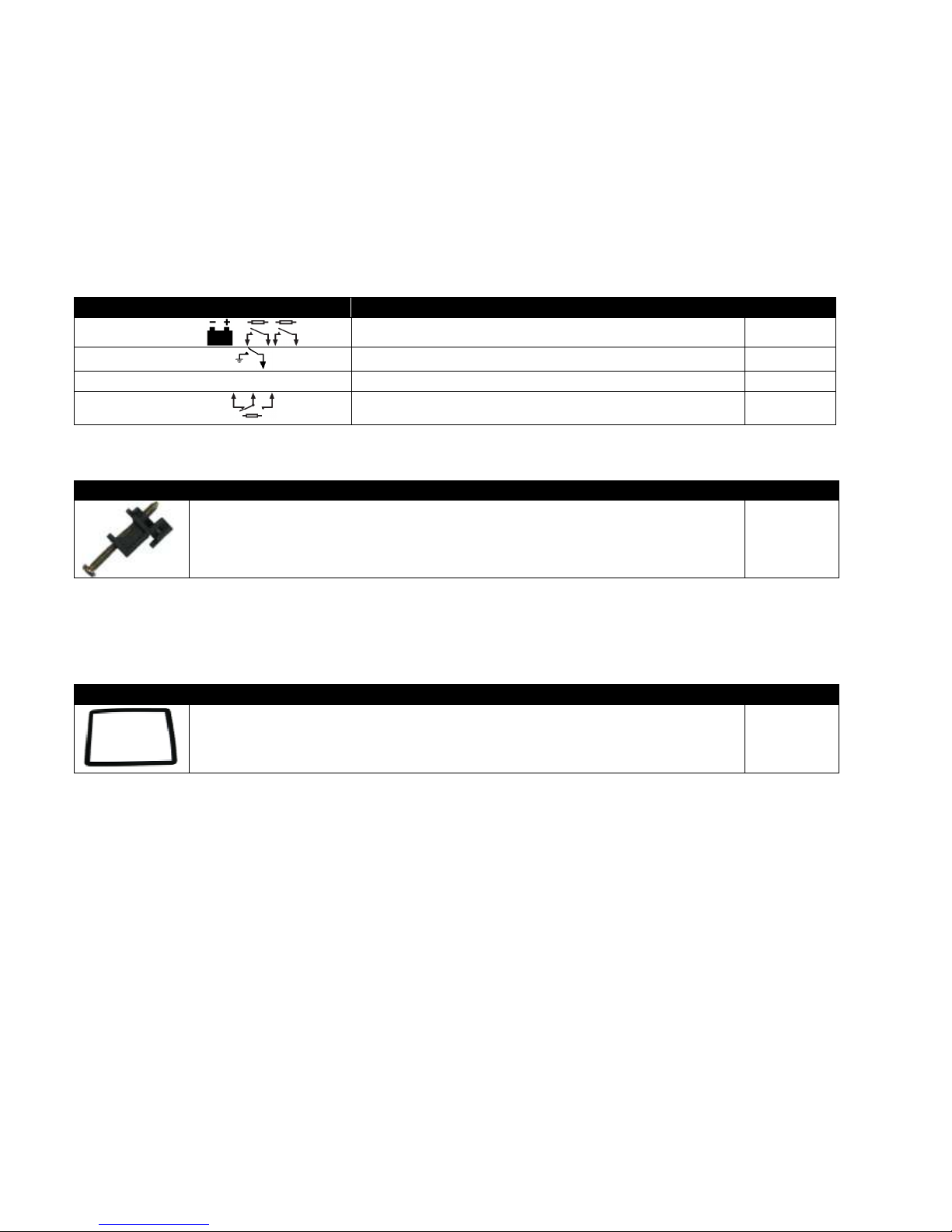
9.1 PURCHASING ADDITIONAL CONNECTOR PLUGS FROM DSE
If you require additional plugs from DSE, please contact our Sales department using the part numbers below.
Module terminal designation Plug description Part No.
1-10
10 way 5.08mm 007-450
11-14
4 way 5.08mm 007-444
15-22
S2 S1
8 way 7.62mm 007-454
23-28
6 way 5.08mm 007-446
9.2 PURCHASING ADDITIONAL FIXING CLIPS FROM DSE
Item Description Part No.
DSE331 / DSE3xx series fixing clips (packet of 2) 020-294
9.3 PURCHASING SEALING GASKET FROM DSE
The optional sealing gasket is not supplied with the controller but can be purchased separately.
Item Description Part No.
DSE331 silicon sealing gasket 020-313
Page 35

Maintenance, Spares, Repairs, Servicing, Warranty, Disposal
35
10 WARRANTY
DSE provides limited warranty to the equipment purchaser at the point of sale. For full details of any applicable
warranty, you are referred to your original equipment supplier (OEM).
11 DISPOSAL
11.1 WEEE (WASTE ELECTRICAL AND ELECTRONIC EQUIPMENT)
Directive 2002/96/EC
If you use electrical and electronic equipment you must store, collect, treat, recycle and dispose of
WEEE separately from your other waste.
11.2 ROHS (RESTRICTION OF HAZARDOUS SUBSTANCES)
Directive 2002/95/EC:2006
To remove specified hazardous substances (Lead, Mercury, Hexavalent Chromium, Cadmium, PBB & PBDE´s)
Exemption Note: Category 9. (Monitoring & Control Instruments) as defined in Annex 1B of the WEEE directive
will be exempt from the RoHS legislation. This was confirmed in the August 2005 UK´s Department of Trade and
Industry RoHS REGULATIONS Guide (Para 11).
Despite this exemption DSE has been carefully removing all non RoHS compliant components from our supply
chain and products.
When this is completed a Lead Free & RoHS compatible manufacturing process will be phased into DSE
production.
This is a process that is almost complete and is being phased through different product groups.
Page 36
Appendix
36
12 APPENDIX
12.1 COMMUNICATIONS OPTION CONNECTIONS
12.1.1 DESCRIPTION
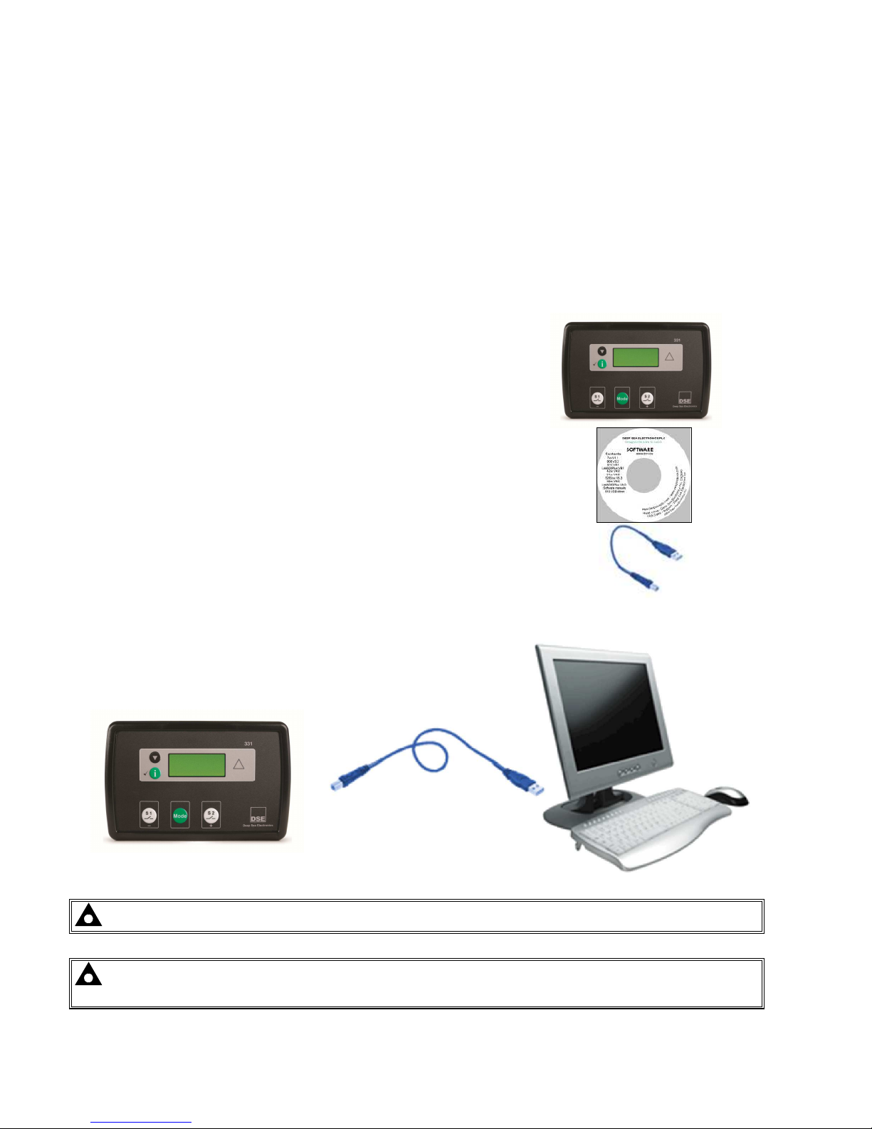
The DSE Configuration Suite software allows the controller to communicate with a PC. The computer connects to
the module as shown below and allows easy adjustment of the operating parameters and firmware update of the
controller.
12.1.2 PC TO CONTROLLER (DIRECT) CONNECTION
To connect a 331 ATS module to a PC the following items are required: -
• DSE331 series module
• Configuration Suite software (Supplied on configuration suite
software CD or available from www.deepseaplc.com).
• USB cable Type A to Type B.
NOTE:- The DC supply must be connected to the module for configuration by PC.
NOTE:- Refer to DSE Configuration Suite software Manual (057-149) for further details on configuring
the module by PC.
Page 37

This Page is Intentionally blank
37
Page 38

This Page is Intentionally blank
38
 Loading...