

Page 1
USER MANUAL
DIGITAL VIDEO DR-N4 / 8/16
Page: - 1 - Page: - 1 - Page: - 1 -
Digital video recorders DR-N4 / DR-N8
/ N16-DR
User Manual
DSE srl - ITALY - WWW.DSE.EU
Page 2

USER MANUAL
DIGITAL VIDEO DR-N4 / 8/16
Page: - 2 - Page: - 2 - Page: - 2 -
1. Product Overview
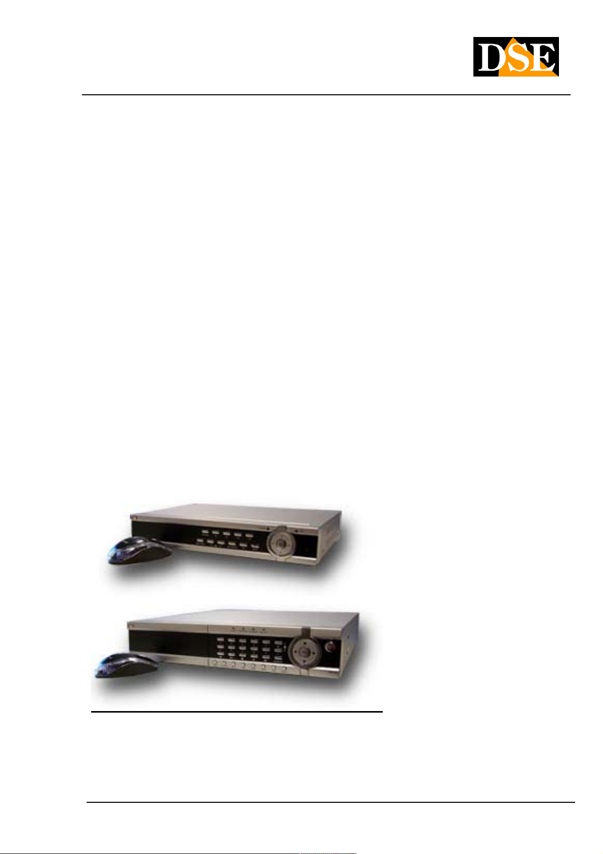
The DR-N video recorders have been developed for professional video surveillance and incorporate in one unit of
digital video recorder hard drive, a multiplexer, and a web server.
1.1 Product Features
• Possibility of connecting 4 (DR-N4), 8 (DR-N8) or 16 (DR-N16) cameras in both color and B / W
• 1 independent audio input for each camera
• H264 Video compression with configurable quality
• ADPC audio compression
• Hexaplex - The unit can not stop recording in case of live viewing, playback, backup, control and remote
access
• PAL Resolution: Selectable D1: 704x576 / HD1: 704x288 / CIF: 352x288
• Frame rate PAL viewing live: real-time 25 f / sec per channel
• Frame rate PAL recording: configurable up to 25 f / sec per channel
• Continuous recording, alarm or on an hourly basis
• Mouse control with on-screen graphic interface
• Playback search by time or event (alarm, motion
• Intelligent Motion detection with programmable area and sensitivity
• Management of air not shown for privacy surveillance in the workplace.
• 4 (DR-N4 / 8) and 16 (DR-N16) alarm inputs and 1 alarm output to external devices
• 1 Hard disk SATA II max. 2TB capacity (DR-N16: 2 HDD only)
• Video / audio backup to USB2.0 storage devices, including USB sticks, external HDD and DVD + RW
recorders, DVD + R, and DVD-R
• Ethernet interface for remote access via web browser, remote alarm notification, remote control speed dome,
tele programming and updating firmware remotely.
• PTZ control capability of speed dome cameras multiprotocol (with SD series cameras use Pelco D). alarm
preset recall.
• Access from mobile devices: iPhone, iPad, Blackberry, 3G / 3.5G phones
• Access via PDA with support for Windows Mobile, Symbian, Android.
• Free App for remote access with advanced features (full screen, PTZ control of speed dome cameras etc).
• Mapping of the gates of automatic UPnP router
• Remote access via the Internet with the video ID
• Menu in Italian (Multilingual programmable)
• Enter password to ensure a high degree of safety.
DSE srl - ITALY - WWW.DSE.EU
Page 3
USER MANUAL
DIGITAL VIDEO DR-N4 / 8/16
Page: - 3 - Page: - 3 - Page: - 3 -
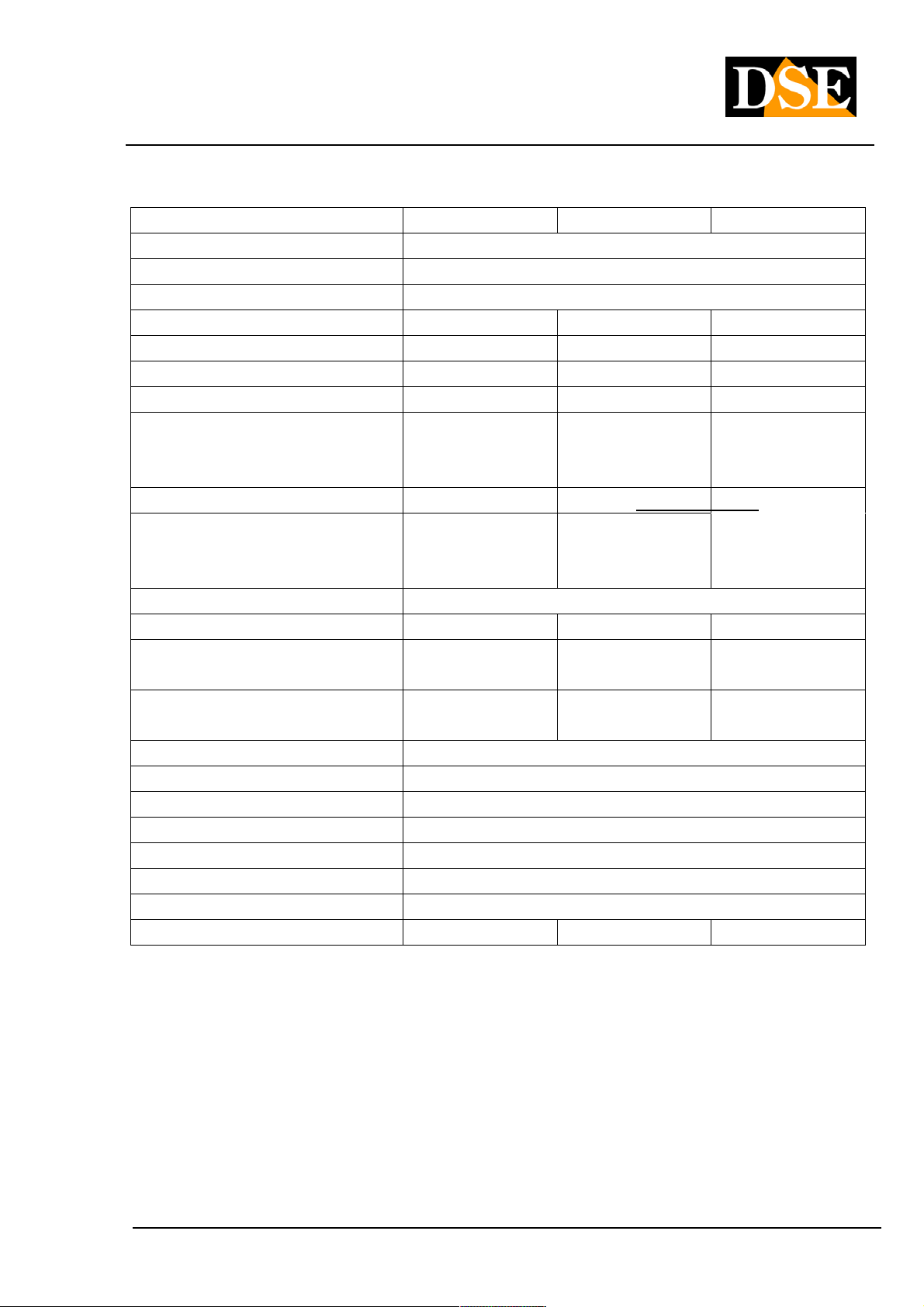
1.2 Specifications
DR-N4 DR-N8 DR-N16
video Format PAL / NTSC / SECAM
video Compression H.264 baseline
audio Format G.726 ADPCM Mono 8Kx16bit
video Inputs 4 BNC 8 BNC 16 BNC
audio Inputs 4 RCA 8 RCA 16 RCA
alarm inputs 4 NO / NC 4 NO / NC 16 NO / NC
alarm outputs 1 1 1
video Resolution CIF 352x288 Half D1
704x288
D1 704x576
Frame rate display 25 f / sec channel 25 f / sec per channel 25 f / sec per channel 25 f / sec channel 25 f / sec per channel 25 f / sec per channel
Total recording frame rate D1: 100 f / sec HalfD1:
100 f / sec CIF: 100 f /
sec
Recording Mode Schedule, manual, alarm, motion detection
Masks privacy Yes Yes Yes
HDD 1 SATA HDD
Max. 2TB
Network port RJ45 10 / 100M RJ45 10 / 100M RJ45 10/100 /
USB2 port Mouse / Portable HDD / Flash Drive / DVD Burner
RS485 port Protocol Pelco P / D, Samsung, Panasonic etc.
video Backup AVI format, MP4, H264
Supply 12VDC power supply provided
Absorption 10-15W
Temperature - 10 + 40 ° C
Humidity 10% -90% RH
Dimensions mm. 315x224x52 315x224x52 435x340x55
CIF 352x288 Half D1
704x288
D1 704x576
D1: 50 f / sec HalfD1:
100 f / sec CIF: 200 f /
sec
1 SATA HDD
Max. 2TB
CIF 352x288 Half D1
704x288
D1 704x576
D1: 100 f / sec HalfD1:
200 f / sec CIF: 400 f /
sec
2 SATA HDD
Max. 2TB
1000M
DSE srl - ITALY - WWW.DSE.EU
Page 4
USER MANUAL
DIGITAL VIDEO DR-N4 / 8/16
Page: - 4 - Page: - 4 - Page: - 4 -
2. controls, connections and remote control
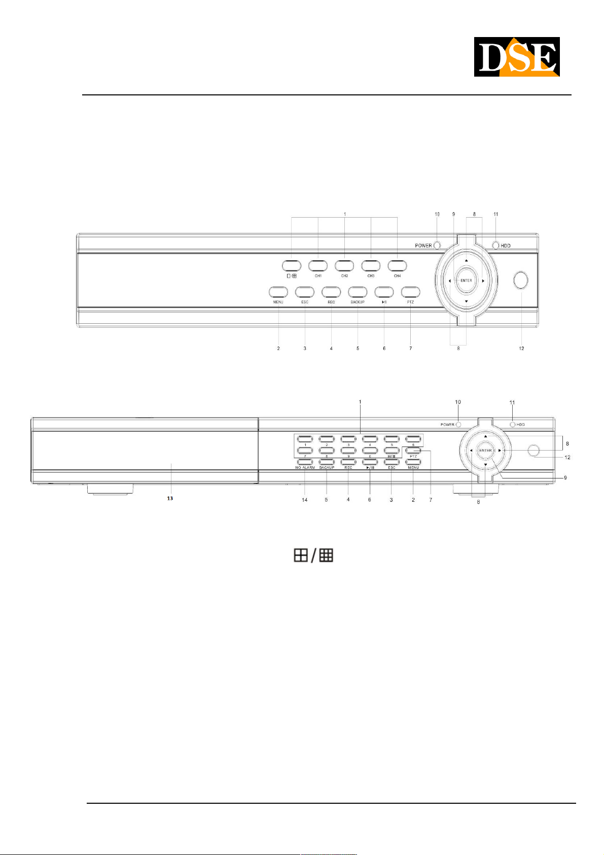
2.1 Front controls
DR-DR-N4 and N8
DR-N16
1 Alphanumeric keys and multivision
They are used to select a camera to display full screen. The multivision button (
) is used to divide the
screen into quadrants to display multiple cameras simultaneously. In the DR-N8-N16 model and DR for space reasons
some buttons control 2 channels: for example, the 1/11 button selects the camera 1 if pressed once and 11 when
pressed two times consecutively.
2 MENU button
Press this button to display the programming menu of the DVR
3 ESC button
Press this button to display or hide the menu bar and system information, or to exit the menu in which you entered.
4 REC button
Pressing this button starts manual recording stops again pressed again. Manual recording is used to record regardless
of the automatic settings that are set in DVR.
DSE srl - ITALY - WWW.DSE.EU
Page 5

USER MANUAL
DIGITAL VIDEO DR-N4 / 8/16
Page: - 5 - Page: - 5 - Page: - 5 -
5 button BACKUP
Pressing this button on the screen window that allows you to examine for films of interest and saving on external media
such as USB keys etc ..
6 Play / Pause (
Press this button to open the search function that lets you search and play back the recorded movies. Also it used to
pause the movie playback.
7 Button PTZ
This button is used to control the movement of Speed Dome cameras connected to the RS485 serial port. Once you
have selected with the mouse or keyboard to control the camera, press this button to open the control panel that
appears on the screen.
8 Button left / right / up / down ( ◄, ►, ▲, ▼)8 Button left / right / up / down ( ◄, ►, ▲, ▼)8 Button left / right / up / down ( ◄, ►, ▲, ▼)
In PTZ control, press these buttons to move the camera. In other situations. press this button to move the cursor or
click on a particular window.
9 ENTER button
This button is used in many cases to confirm the data.
10 Light POWER
Indicator light for ignition.
11 Light HDD
Indicator light for switched to the hard disk.
)
12 IR Receiver
It receives the signal sent to it from the remote control. Avoid obstacles that can interfere in the signal direction.
13 Front Tray (DR-N16 ONLY)
Accesses the pull-out drawer for removable disk.
14 Button NO ALARM14 Button NO ALARM
Pressing this button will access the alarm source screen to silence any kind of alarm or buzzer.
DSE srl - ITALY - WWW.DSE.EU
Page 6
USER MANUAL
DIGITAL VIDEO DR-N4 / 8/16
Page: - 6 - Page: - 6 - Page: - 6 -
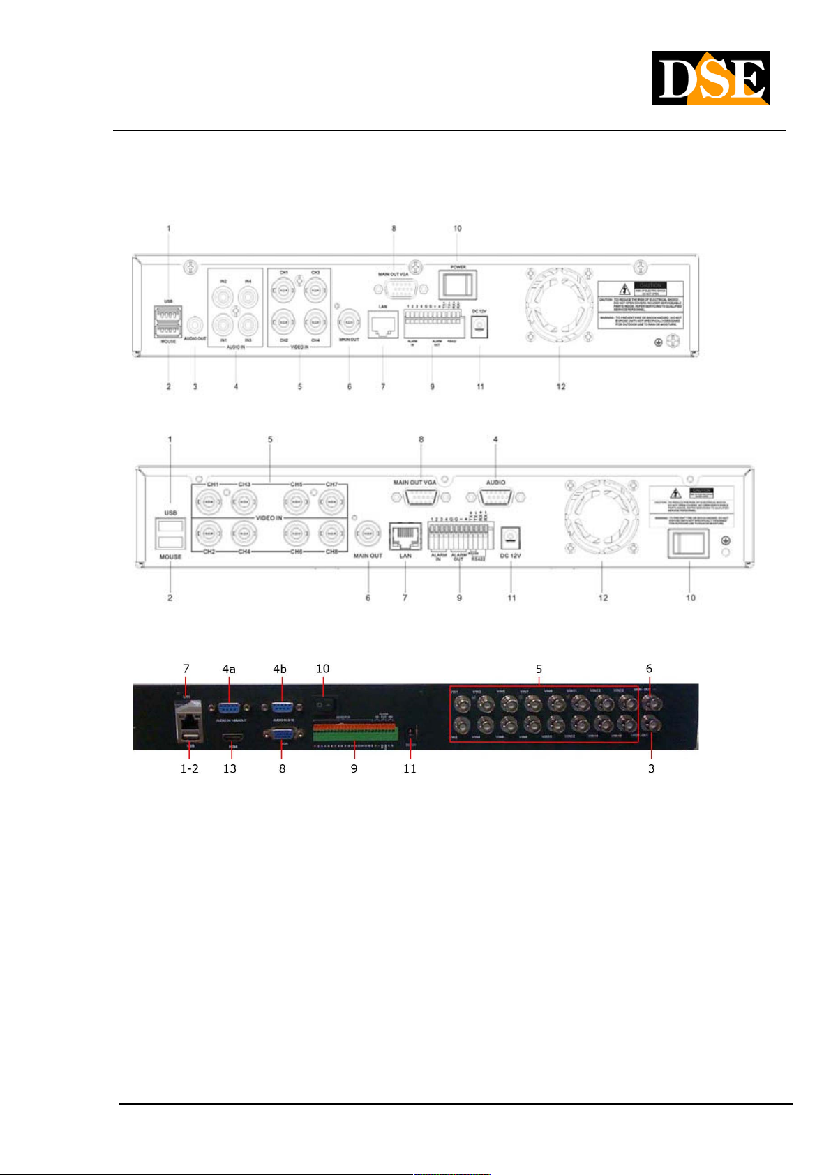
2.2 Connections
DR-N4
DR-N8
DR-N16
1 USB port
Connect an external USB device like a USB stick, an external HDD or a DVD burner. The maximum current that the
VCR is able to provide to the USB device, if this is not provided with their own autonomous power supply is 500 mA.
This port only supports drives with FAT32 file system.
2 Port MOUSE
It allows to connect the mouse to the VCR. The mouse is not required for use of the device but faster and more
convenient to use than the front buttons, and we recommend that you always connect if the position of the DVR allows
you to use it.
3 (DR-N16 only) - auxiliary video output connector (CALL OUT)
DSE srl - ITALY - WWW.DSE.EU
Page 7

USER MANUAL
DIGITAL VIDEO DR-N4 / 8/16
Page: - 7 - Page: - 7 - Page: - 7 -
BNC connector to connect a secondary external monitor said CALL. The monitor said no CALL visualises the menu,
but only images from the cameras. Compared to the main output monitor it has an independent display showing
programming and can cycle the cameras and bring up specific cameras according to alarm events.
3 (DR-N4 only) - Audio output connector (AUDIO OUT)
This RCA connector allows you to connect an external audio speakers to play the sound live or recorded. In DR-N8 /
16 models this output is also available, but is included in the audio cable supplied.
4 Audio Input Connectors (AUDIO IN)
The DR VCRs include one audio input for each camera to record audio along with the video. In the model DR-N4 I audo The DR VCRs include one audio input for each camera to record audio along with the video. In the model DR-N4 I audo The DR VCRs include one audio input for each camera to record audio along with the video. In the model DR-N4 I audo
the inputs are composed of 4 RCA connectors and serve to connect the audio inputs from the cameras or from external
microphones. In the model DR-N8, for reasons of space, the RCA connectors for audio are not directly placed on the microphones. In the model DR-N8, for reasons of space, the RCA connectors for audio are not directly placed on the microphones. In the model DR-N8, for reasons of space, the RCA connectors for audio are not directly placed on the
DVR but are on a cable supplied separately to connect to the D-SUB connector labeled Audio. This cable also allows
you to connect an external speaker to play back the recorded audio (AUDIO OUT). In the model DR-N16 They are you to connect an external speaker to play back the recorded audio (AUDIO OUT). In the model DR-N16 They are you to connect an external speaker to play back the recorded audio (AUDIO OUT). In the model DR-N16 They are
supplied separately to the well 2 adapters and cables are located on the DVR 2 D-SUB ports. The AUDIO IN port 1-8
allows to connect the microphones from 1 to 8 and the speaker output. The AUDIO 9-16 allows you to connect
microphones of the remaining cameras.
5 Video Input Connectors (1-16)
Connect cameras to these BNC connectors. If the cable has RCA connectors use special adapters RCA / BNC
6 main video output connector (MAIN OUT)
BNC connector for connecting the analog type main external monitor. It display all the windows even if the video signal
is absent and provides access to the programming menu.
7 Ethernet RJ45 socket
10/100 Ethernet connection for remote access from a PC.
8 VGA connector
VGA connector for connecting a computer to type PC monitor. And 'possible to directly connect a monitor with a VGA
cable. This replica output exactly the analog BNC output named MAIN. The DR series VCRs support maximum
1440x900 resolution in 4: 3 and 16: 9 If you have set an unsupported resolution on your monitor so there is precluded
the display can restore the 800x600 VGA resolution by pressing the ESC + 2 keyboard and 2 + ESC
Terminal block 9 inputs / alarm outputs and serial ports
This terminal allows you to connect different types of devices.
ALARM INPUTS - As alarm inputs are intended sensors or external contacts capable of generating alarm and start ALARM INPUTS - As alarm inputs are intended sensors or external contacts capable of generating alarm and start
recording ( ALARM IN).recording ( ALARM IN).
ALARM OUTPUT - The alarm outputs allow to connect external devices, such as acoustic, flashing alarms, lighting, etc. ALARM OUTPUT - The alarm outputs allow to connect external devices, such as acoustic, flashing alarms, lighting, etc.
to operate in case of alarm ( ALARM OUT).to operate in case of alarm ( ALARM OUT).
DSE srl - ITALY - WWW.DSE.EU
Page 8
USER MANUAL
DIGITAL VIDEO DR-N4 / 8/16
Page: - 8 - Page: - 8 - Page: - 8 -
PORT RS485 - The serial port is used to send commands to motorized speed dome cameras ( RS485).PORT RS485 - The serial port is used to send commands to motorized speed dome cameras ( RS485).PORT RS485 - The serial port is used to send commands to motorized speed dome cameras ( RS485).
10 ON / OFF
switching on and off switch.
11 Power connector
Connect the power supply 12VDC.
12 Cooling Fan
Fan for the cooling of the hard disk.
13 HDMI Video output (DR-N16 only)
The only DR-N16 model includes another type of HDMI video output to connect a TV-like monitor.
2.3 Remote Control
The remote is a standard accessory with the DVR to facilitate the user. You can perform all the functions with the
remote control at a distance instead of going to select the front panel. The effective distance is about 10 meters
without any obstacle.
The DR-N keyboard also has only the essential buttons for operation, while several additional functions are only
available using the mouse or remote control.
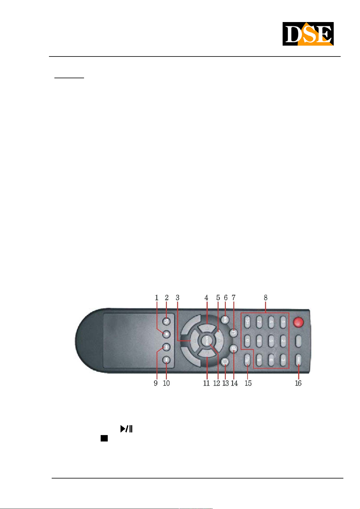
Below a picture of the remote control whose design can be different depending on the model.
commands
Most of the buttons on the remote replication the keys on the DVR keyboard. There are also the following
additional functions:
1 - Play / Paua ( 1 - Play / Paua (
2 - Stop () Stop playback 2 - Stop () Stop playback
3/4/5/11 - Moving - Motion arrows in all directions 3/4/5/11 - Moving - Motion arrows in all directions
6 - Menu / ESC - Press to open the programming menu and to exit 6 - Menu / ESC - Press to open the programming menu and to exit 6 - Menu / ESC - Press to open the programming menu and to exit 6 - Menu / ESC - Press to open the programming menu and to exit
) To search for movies, play, and pause
DSE srl - ITALY - WWW.DSE.EU
Page 9

USER MANUAL
DIGITAL VIDEO DR-N4 / 8/16
Page: - 9 - Page: - 9 - Page: - 9 -
7 - Log in - Press to log-in and log-out 7 - Log in - Press to log-in and log-out 7 - Log in - Press to log-in and log-out 7 - Log in - Press to log-in and log-out
8 - Numerical buttons (1-9, 0, 10+) cameras and inserting texts Selection 8 - Numerical buttons (1-9, 0, 10+) cameras and inserting texts Selection 8 - Numerical buttons (1-9, 0, 10+) cameras and inserting texts Selection
9 - Fast Backward ( 9 - Fast Backward (
10 - Fast Forward ( 10 - Fast Forward (
12 - Enter 13 - Scan - Starts and stops the cyclical scanning 12 - Enter 13 - Scan - Starts and stops the cyclical scanning
14 - Audio ON / OFF 14 - Audio ON / OFF 14 - Audio ON / OFF 14 - Audio ON / OFF
15 - Multivision Change the screen division. 15 - Multivision Change the screen division.
16 - REC Start manual recording16 - REC Start manual recording
Any other buttons on the remote control other than those described have no application of these models.
) Fast backward playback
) fast forward
DSE srl - ITALY - WWW.DSE.EU
Page 10
USER MANUAL
DIGITAL VIDEO DR-N4 / 8/16
Page: - 10 - Page: - 10 - Page: - 10 -
3. Installation
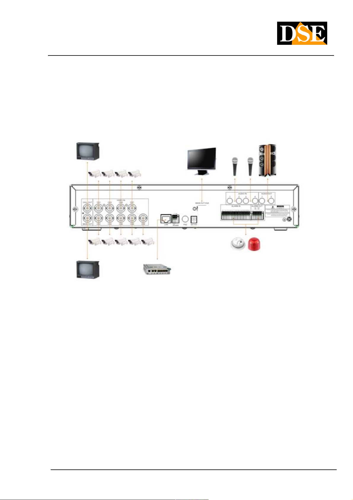
3.1 Basic Connections
Before turning on the VCR is necessary to arrange the connections with the peripheral units which we explain
below.
• Connect cameras
The cameras are connected to the BNC Video IN (channel 1 ... 16). If the cable you have available has RCA
connectors you must use a RE-BNCRCA1 adapter. The inputs support a standard analog video signal 1
Vp-p 75 Ohm.
• Connect the main monitor
A classic CRT or LCD monitor or a TV can be connected to the MAIN OUT with BNC attack. It 'also possible
to connect a PC to the VGA monitor. In DR-N16 model it is also possible to connect a TV monitor to the
HDMI output.
Without monitor the DVR can run but you can not control it.
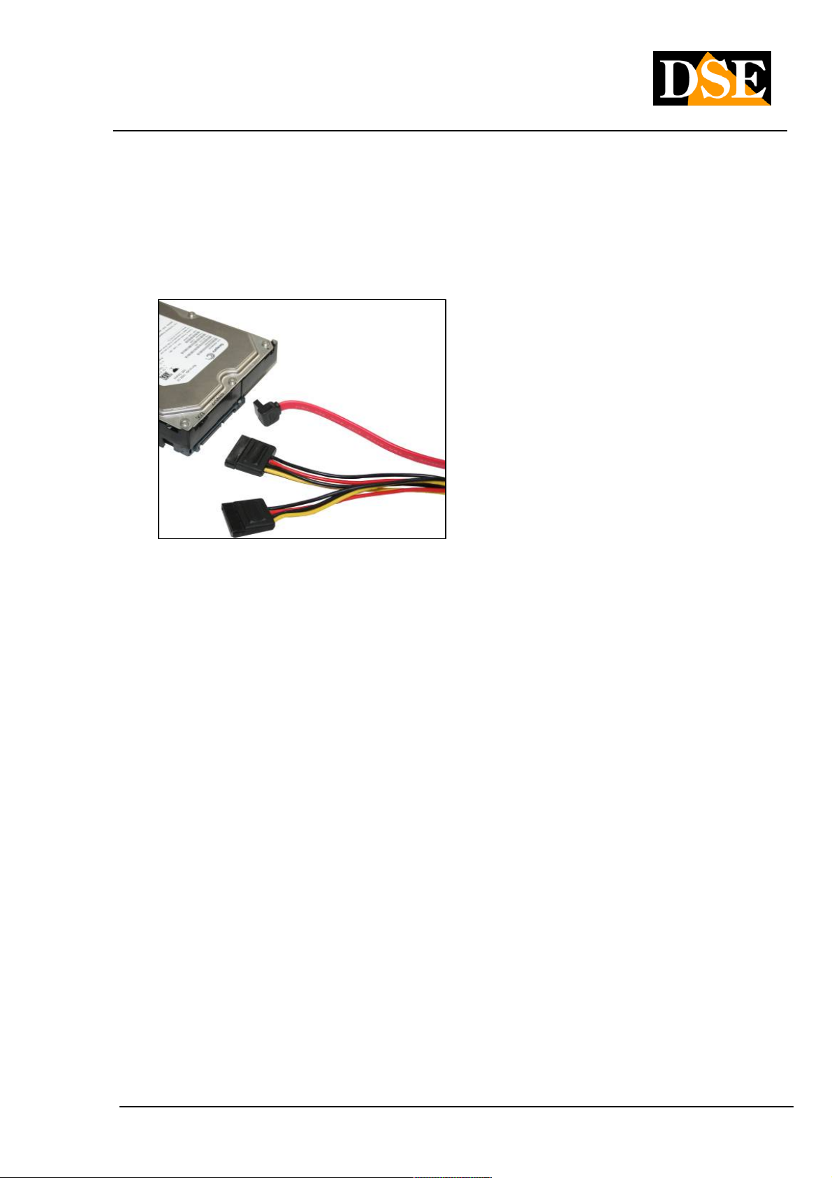
• hard disk installation
Because the DVR is capable of recording, you need to install the hard drive inside the equipment. Before
installation make sure the hard drive is the SATA type 3.5 " Then install the hard disk as follows: installation make sure the hard drive is the SATA type 3.5 " Then install the hard disk as follows: installation make sure the hard drive is the SATA type 3.5 " Then install the hard disk as follows:
1. Turn off the appliance open the VCR by removing the 1. Turn off the appliance open the VCR by removing the
DSE srl - ITALY - WWW.DSE.EU
Page 11
USER MANUAL
DIGITAL VIDEO DR-N4 / 8/16
Page: - 11 - Page: - 11 - Page: - 11 -
superior protection by unscrewing the lateral fixing screws.
2. Attach the hard disk unit in its seat by means of the screws 2. Attach the hard disk unit in its seat by means of the screws
fixing.
3. Connect the red SATA cable for data and power cable between hard drive and motherboard.
4. Close the device with the lid by screwing the screws. 4. Close the device with the lid by screwing the screws.
The DR-N16 VCR also features a front drawer in which you can, if necessary, install a second hard drive
removed from the front.
CAUTION: Before you start recording you must perform physical formatting of the hard drive CAUTION: Before you start recording you must perform physical formatting of the hard drive
according to the instructions below in section 6.
• feeder Connection
Connect the power supply 220VAC / 12VDC supplied to the rear connector 12VDC
3.2 Other connesioni
• audio Inputs
Camera equipped with separate microphone or microphones can be connected to the VCR through the
AUDIO IN inputs. The inputs support standard analog audio 2Vp-p 600 Ohm. Use microphones active type.
• audio Outputs
You can connect speakers, headphones or other external audio equipment such as a TV audio inputs and
monitor. This way you can hear the sound from the microphone inputs and during playback.
• LAN
The connection to the VCR network takes place via the outlet of the rear RJ45 network. Before using the
LAN connection set parameters
DSE srl - ITALY - WWW.DSE.EU
Page 12

USER MANUAL
DIGITAL VIDEO DR-N4 / 8/16
Page: - 12 - Page: - 12 - Page: - 12 -
network in the DVR setup menu.
• USB 2.0
If the user wants to use USB 2.0 devices to save audio / video recordings, you can connect the device to the
VCR through the appropriate rear USB port. You can connect USB flash drives, USB Hard Disk and DVD
burners.
• MOUSE USB
A second USB port is provided to connect the supplied mouse. The control with the mouse is much easier
and faster than by keyboard or remote control and for this reason in this manual will generally rifermento to
commands with the mouse.
• CALL OUT (only in DR-N16)
E 'can connect a second TV monitor for surveillance through the CALL OUT output. Depending on the
programming this monitor only displays the full screen images of the cameras when they occur alarm events
(alarm or motion) or the images of all cameras sequentially. It allows control of the programming menu.
• Alarm inputs
Terminals 1-4 (DR-N4 / 8) and 1-16 (DR-N16) - Allow to connect external alarm sensors that can enable
logging and generate alarm actions. Connect the contact between the alarm terminals (1 ... 16) and common
terminals G present in the terminal. In programming it is possible to define whether to consider the contacts
as Normally Open (NO) or normally closed (NC).
• Alarm output
The DVR feature 1 relay alarm output for external alarm devices. What can be activated following the rilavati
of alarm events from the DVR. In this case the output is a clean contact Normally Open (NO) consists of 2
terminals denominated NO and COM ..
• PTZ Cameras
The VCR is capable of controlling motorized speed dome cameras via RS485 serial line. The RS485 BUS
part from the terminals A and B of the video recorder to be connected to RS485 terminals A and B of the
cameras according to the directions provided by the manufacturer of the camera (some cameras reported +/-
instead of A / B). The communication settings (protocol, speed, etc. of the bus) is operating in RS485
configuration menu of the DVR and must be consistent with the commands accepted by the cameras used.
The DR series DVR support PelcoD protocol used by DSE speed dome cameras, and various other
protocols from other manufacturers ..
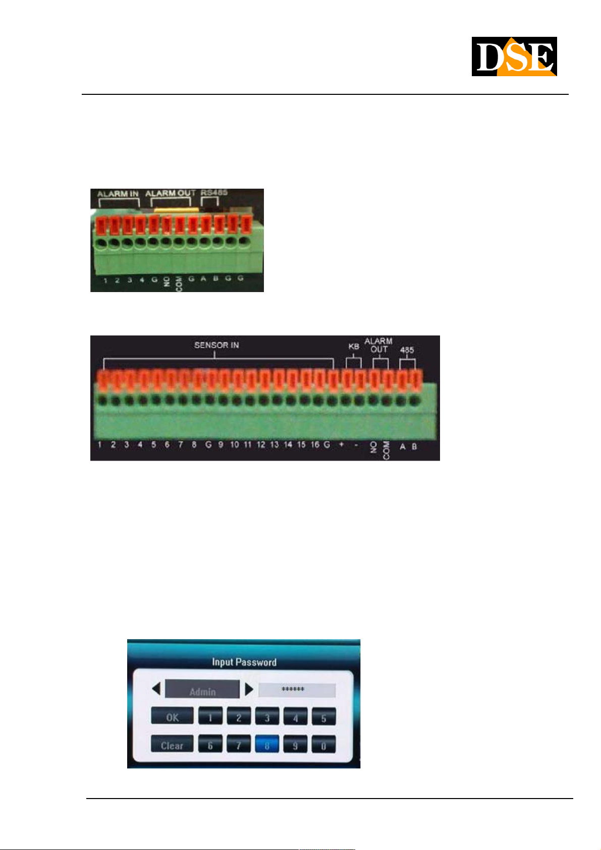
For convenience we report the image of the rear terminal blocks
DSE srl - ITALY - WWW.DSE.EU
Page 13
USER MANUAL
DIGITAL VIDEO DR-N4 / 8/16
Page: - 13 - Page: - 13 - Page: - 13 -
Model DR-N4 / 8
DR-N16 Model
3.3 Language Selection
The DR VCRs are provided with the default setting of English. This manual is for convenience to the instructions
in Italian, so as a preliminary step necessary to set the Italian language in the configuration options. The
procedure is as follows:
• Turn on your DVR
Press the ON / OFF button and wait until the startup is completed
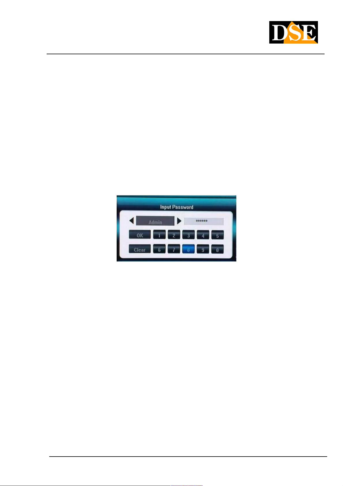
• Press MENU
Enter the corresponding administrator password. Factory ( Admin: Enter the corresponding administrator password. Factory ( Admin:
888888)
DSE srl - ITALY - WWW.DSE.EU
Page 14

USER MANUAL
DIGITAL VIDEO DR-N4 / 8/16
Page: - 14 - Page: - 14 - Page: - 14 -
• Login
Press ENTER
• Press MENU
Select the SYSTEM menu with the arrow keys or the mouse and go to the item LANGUAGE
• Choose the language ITALIAN
Select the Italian language
• SAVE Menu
Select the SAVE menu after which the option SAVE AND EXIT
After that the VCR will be presented in Italian.
WARNING - If the configuration menu does not appear on the screen to see the next paragraph.
3.4 Selection of the screen displaying the menu
The DR-N4 video recorders and DR-N8 show the programming menu only on a video output or BNC or VGA, not
both.
If you have connected only one monitor and see not appear the programming menu by pressing the MENU
button it is very likely have to switch the main screen.
To move the menu display from one monitor to press in sequence ESC ESC + 1 + on the keyboard.To move the menu display from one monitor to press in sequence ESC ESC + 1 + on the keyboard.To move the menu display from one monitor to press in sequence ESC ESC + 1 + on the keyboard.
Each press of this sequence, the menu moves from the VGA to BNC and vice versa.
DSE srl - ITALY - WWW.DSE.EU
Page 15
USER MANUAL
DIGITAL VIDEO DR-N4 / 8/16
Page: - 15 - Page: - 15 - Page: - 15 -
4. Before ignition and basic operations 4. Before ignition and basic operations
4.1 Information on the live video
Turn on the DVR and wait for the completion of the start-up. If the hard disk is not installed, the buzzer will signal and a
message appears on the screen.
Before you can perform any operation on the DVR you have to login with the Log In procedure. Press the right mouse Before you can perform any operation on the DVR you have to login with the Log In procedure. Press the right mouse
button or the ESC button on the keyboard, or even the LOGIN button with the padlock on the remote control: the login
window will appear.
WARNING - If the configuration menu does not appear on the screen to see the previous section and
press ESC + 1 + ESC.
The default password is as follows.
Admin: 888888 User:
666666
You can use these settings unchanged to use the system for the first time and become familiar with the system, only to
change them in the configuration.
If the user had forgotten administrator password, there is a hardware reset procedure to see later.
You can enter up to 7 users: an administrator and six users with different levels of fully configurable access.
To turn off your DVR, press the POWER button icon in the menu bar, enter the password to turn off, then bring back
the ON / OFF switch to OFF.
DSE srl - ITALY - WWW.DSE.EU
Page 16
USER MANUAL
DIGITAL VIDEO DR-N4 / 8/16
Page: - 16 - Page: - 16 - Page: - 16 -
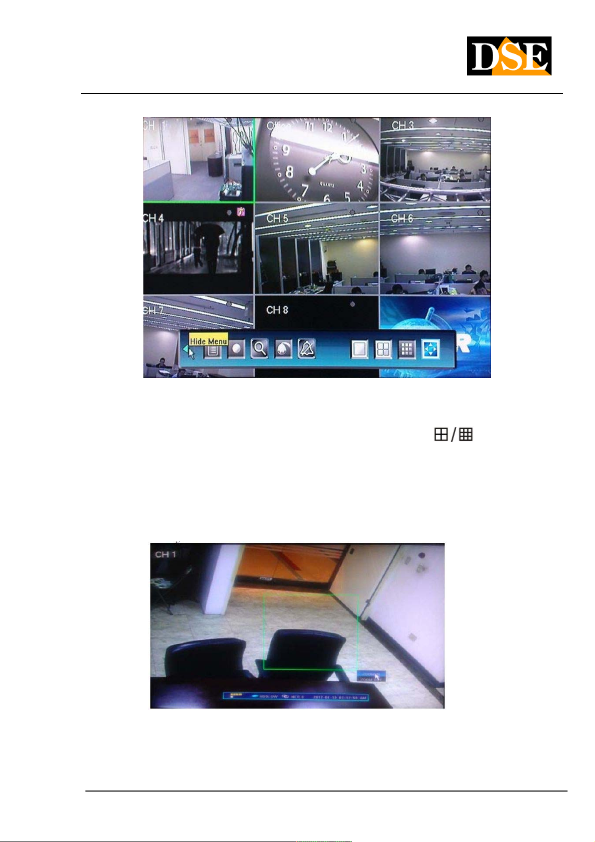
The main screen shown on the monitor after booting the system is the multi-vision camera as shown above. You can
view other options by pressing the split screen multi-image button (
keyboard or remote control. It 'also possible to bring only one camera in full screen by pressing the corresponding
channel button or by double clicking on the image with the mouse. Another double-click brings to Multivision.
In the vision of a single camera in full screen it is possible to carry out the digital zoom of a detail drawing the interest In the vision of a single camera in full screen it is possible to carry out the digital zoom of a detail drawing the interest In the vision of a single camera in full screen it is possible to carry out the digital zoom of a detail drawing the interest
frame with the mouse while holding down the left mouse button.
36%
) on the
Pressing the ESC button on the keyboard or the right mouse button, or even the MENU button on the remote control,
will appear at the lower screen bar system information, which is as follows:
DSE srl - ITALY - WWW.DSE.EU
Page 17
USER MANUAL
DIGITAL VIDEO DR-N4 / 8/16
Page: - 17 - Page: - 17 - Page: - 17 -
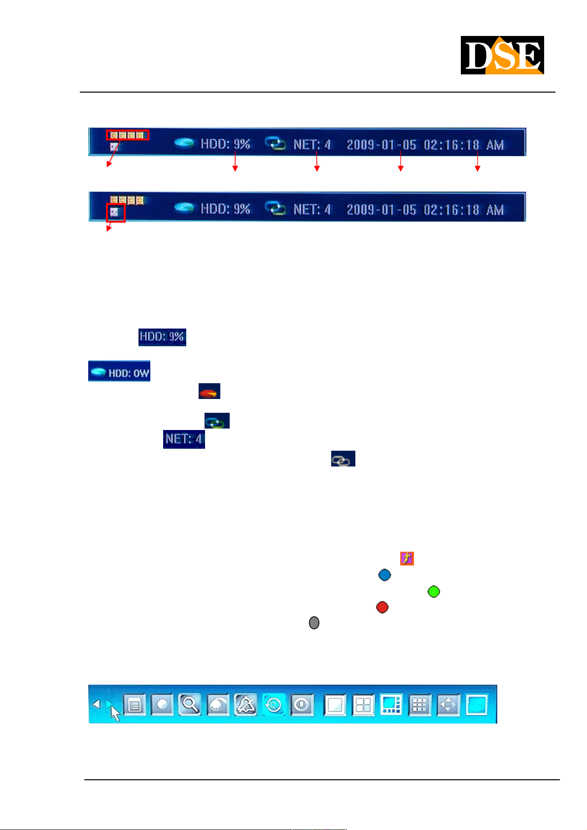
Alarm inputs State Hard Disk Network Date Now
State of alarm outputs
In the lower left of the screen appear icons regarding the status of inputs and alarm outputs, when activated turns red.
The display changes depending on the DVR model. Starting at the top left are all the icons of the alarm inputs. The
latest series of icons representing the alarm outputs.
Afterwards you have the right information to the hard drive The following indication
It indicates the percentage of registered disk space. If it is active
the option to overwrite and the DVR are overwriting older files icon appears
. If the HDD is faulty or not recognized by the DVR Hard Disk icon
turns red
A indication Hard Disk left is the icon that is for the network connection. If the network icon is blue
remote clients.
remote (maximum 24). If the network icon is gray
connected to a network. On the right we finally find information about the current date and time.
Status information of each camera
Each view window can appear in the top right icon that indicates the current status:
the camera has detected a movement "motion detection" •the camera has detected a movement "motion detection" •
the camera is in a normal scheduled recording •the camera is in a normal scheduled recording •
the camera is recording activated by "motion detection" •the camera is recording activated by "motion detection" •
the camera is recording triggered by an alarm •the camera is recording triggered by an alarm •
the camera and manual recording •the camera and manual recording •
.
it indicates that the network connections
indicates the number of channels that are connection object
It means that no client is
4.2 Toolbar
DSE srl - ITALY - WWW.DSE.EU
Page 18

USER MANUAL
DIGITAL VIDEO DR-N4 / 8/16
Page: - 18 - Page: - 18 - Page: - 18 -
On the main screen, press ENTER, or the key twice ESC or the right mouse button to display the toolbar shown above. On the main screen, press ENTER, or the key twice ESC or the right mouse button to display the toolbar shown above. On the main screen, press ENTER, or the key twice ESC or the right mouse button to display the toolbar shown above. On the main screen, press ENTER, or the key twice ESC or the right mouse button to display the toolbar shown above. On the main screen, press ENTER, or the key twice ESC or the right mouse button to display the toolbar shown above.
The depicted icons represent the following commands:
• Hide Toolbar
• Take the Next Page toolbar
• System configuration (see below)
• manual recording
• Search recorded video and backup
• PTZ control (speed dome cameras)
• Tacita alarm. Pressing the button displays the window with
alarm information
• Fast playback - If we press this icon we have the
chance to see the last period of recording made (from 10 seconds to 60 seconds earlier) or quickly search images
according to date and time.
• DVR Shutdown
• Multivision Management - Allows you to choose how many cameras
simultaneously view: one, 4, 6, 9, 16 cameras
DSE srl - ITALY - WWW.DSE.EU
Page 19
USER MANUAL
DIGITAL VIDEO DR-N4 / 8/16
Page: - 19 - Page: - 19 - Page: - 19 -
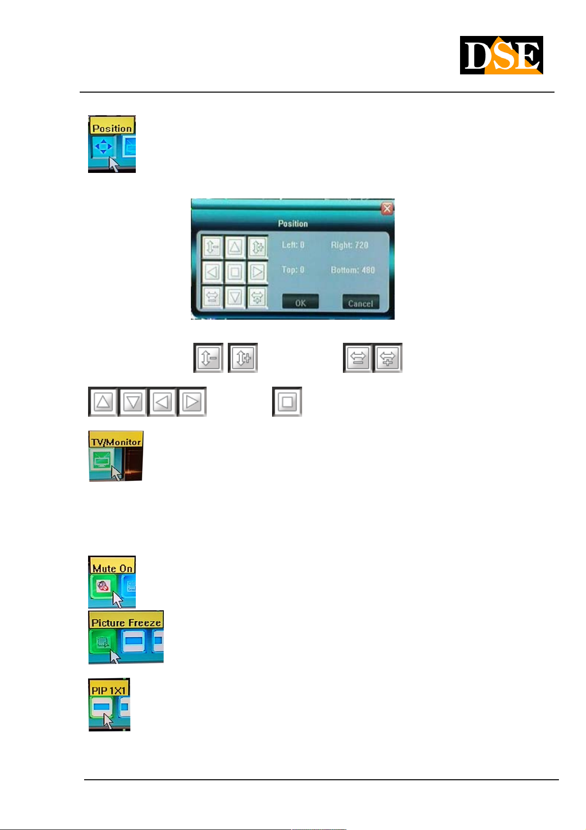
• To adjust the screen display according to the monitor you
is using, you will see a call POSITION adjustment window.
In this window you can reduce or increase the size of a
screen in portrait
move the display screen at the top, bottom, left, right
. The button It allows to center and expand the
can the display screen.
• Step MENU from BNC VGA output. These DVRs allow
display control menu output only choice is VGA and BNC. If you are connected all 2 types of monitors, pressing this
button you can move on the screen display (VGA to BNC and vice versa). The same result can also be achieved by
pressing on the keyboard keys in sequence '' ESC '' '' CH1 '' '' ESC ''. This key combination is essential if you have a single pressing on the keyboard keys in sequence '' ESC '' '' CH1 '' '' ESC ''. This key combination is essential if you have a single pressing on the keyboard keys in sequence '' ESC '' '' CH1 '' '' ESC ''. This key combination is essential if you have a single pressing on the keyboard keys in sequence '' ESC '' '' CH1 '' '' ESC ''. This key combination is essential if you have a single pressing on the keyboard keys in sequence '' ESC '' '' CH1 '' '' ESC ''. This key combination is essential if you have a single pressing on the keyboard keys in sequence '' ESC '' '' CH1 '' '' ESC ''. This key combination is essential if you have a single pressing on the keyboard keys in sequence '' ESC '' '' CH1 '' '' ESC ''. This key combination is essential if you have a single
monitor.
• To enable or disable the sound
and horizontally . It is also possible
• Freeze - This option allows you to freeze
the screen image during live viewing
• PIP - Allows viewing of two cameras, a full screen
and the other in a smaller window that you can move to your liking.
DSE srl - ITALY - WWW.DSE.EU
Page 20
USER MANUAL
DIGITAL VIDEO DR-N4 / 8/16
Page: - 20 - Page: - 20 - Page: - 20 -
In the small window (PIP) you can see a camera at will. To switch from one camera to another is just click on the pane.
• 2X PIP - As above with 2 PIP windows. Allows viewing of three
cameras, a full screen and the other two smaller windows.
4.3 Formatting the hard disk 4.3 Formatting the hard disk
The first operation to be performed after making the LOGIN is the FORMATTING OF THE HARD DISK to be able to
proceed with registration.
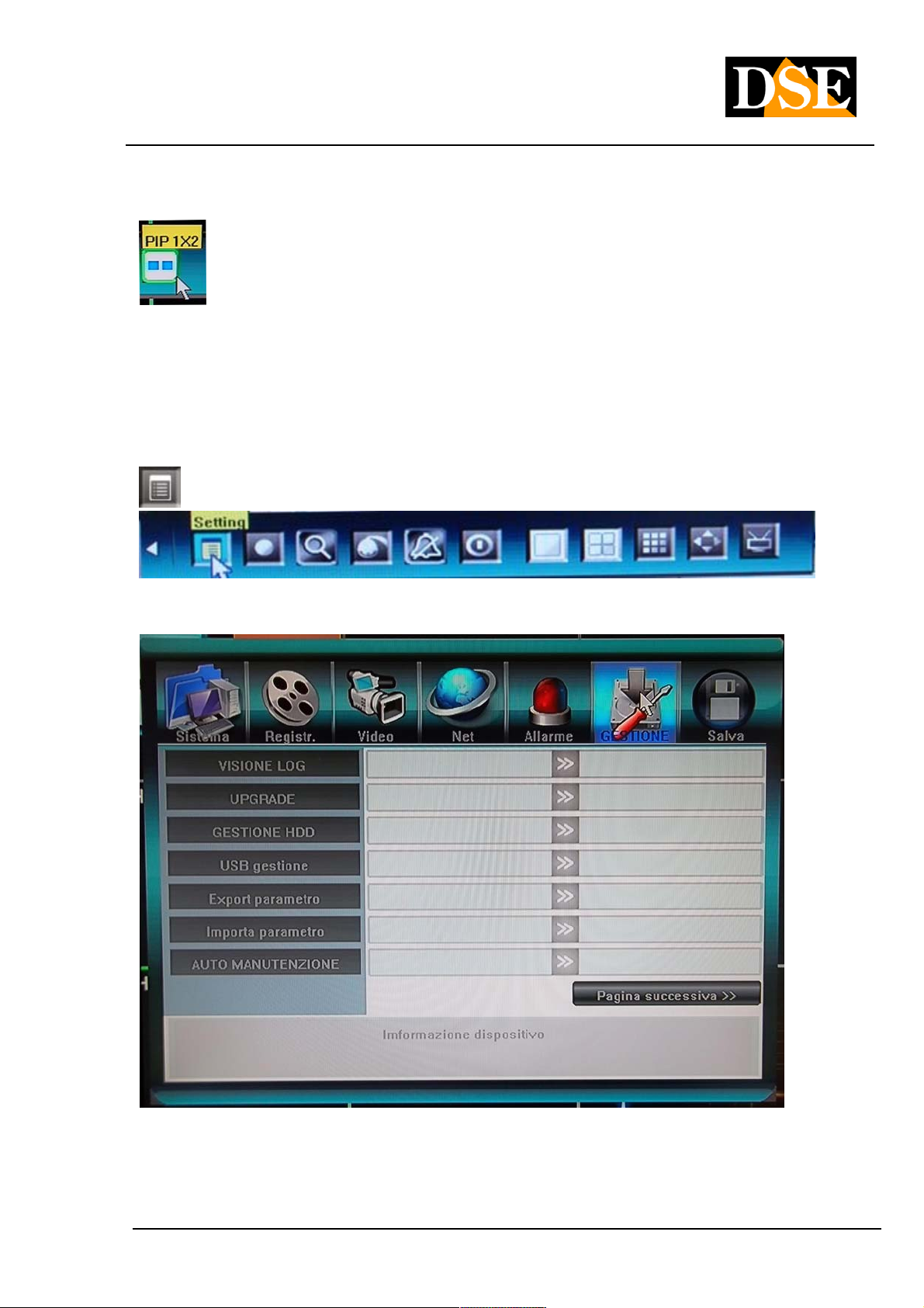
Make the LOGIN as ADMINISTRATOR then enter the SYSTEM CONFIGURATION that in the tool bar is well Make the LOGIN as ADMINISTRATOR then enter the SYSTEM CONFIGURATION that in the tool bar is well
represented
.
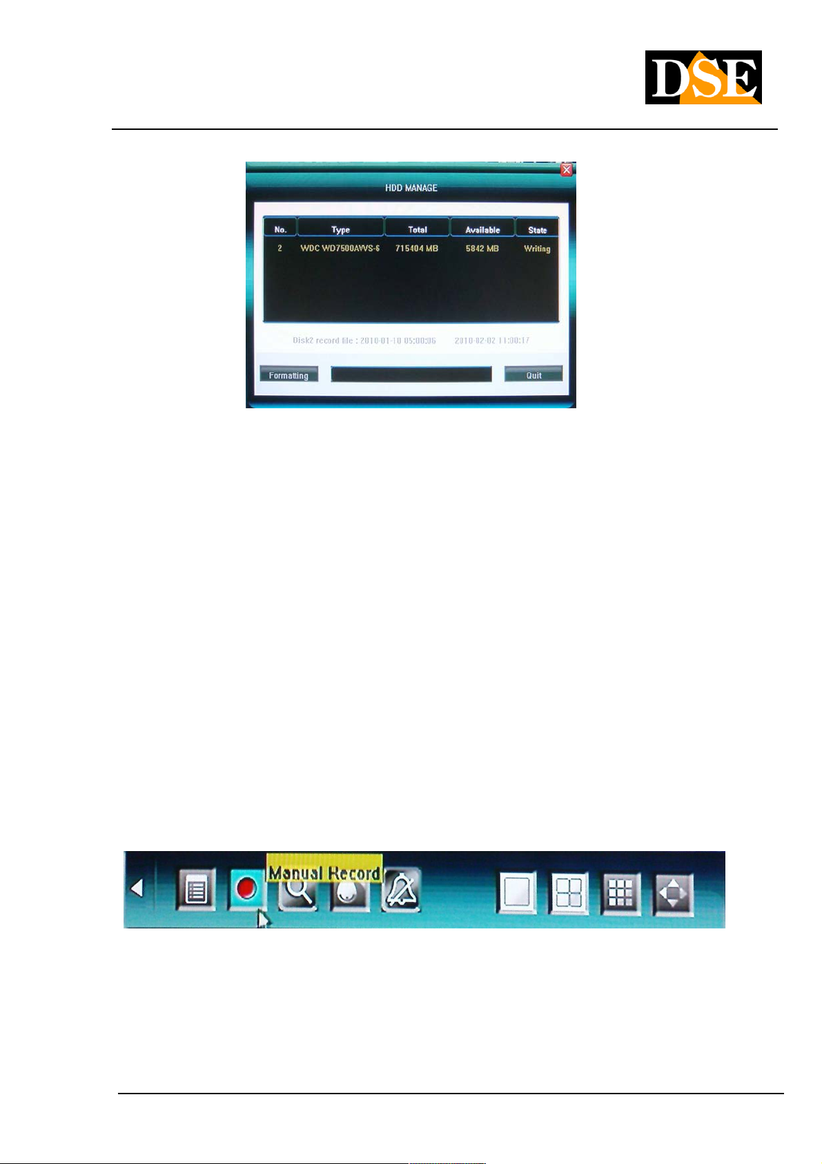
After that enter the section called MANAGEMENT menu, then click the HDD MANAGEMENT voice
It will appear on a window screen that lists the hard disk installed in the DVR indicating the reference, the total
capacity, available space and HDD status. capacity, available space and HDD status.
DSE srl - ITALY - WWW.DSE.EU
Page 21
USER MANUAL
DIGITAL VIDEO DR-N4 / 8/16
Page: - 21 - Page: - 21 - Page: - 21 -
To format FORMAT click on the button, then click on OK in the window that will indicate FORMAT COMPLETED. By
this time the DVR is ready to record.
4.4 registration 4.4 registration
There are two ways to control the recording of the DVR DR series: Manual Record and Schedule Record. Programmed There are two ways to control the recording of the DVR DR series: Manual Record and Schedule Record. Programmed There are two ways to control the recording of the DVR DR series: Manual Record and Schedule Record. Programmed
recording allows you to determine the operation of the DVR during the week at various times of the day. Manual
recording allows you to manually start recording in case you need to be sure to record the current images regardless of
the programmed settings. For this manual recording has priority over schedule recording.
In addition to these two methods there is the possibility of recording in response to an alarm generated by an external
input or by motion detection.
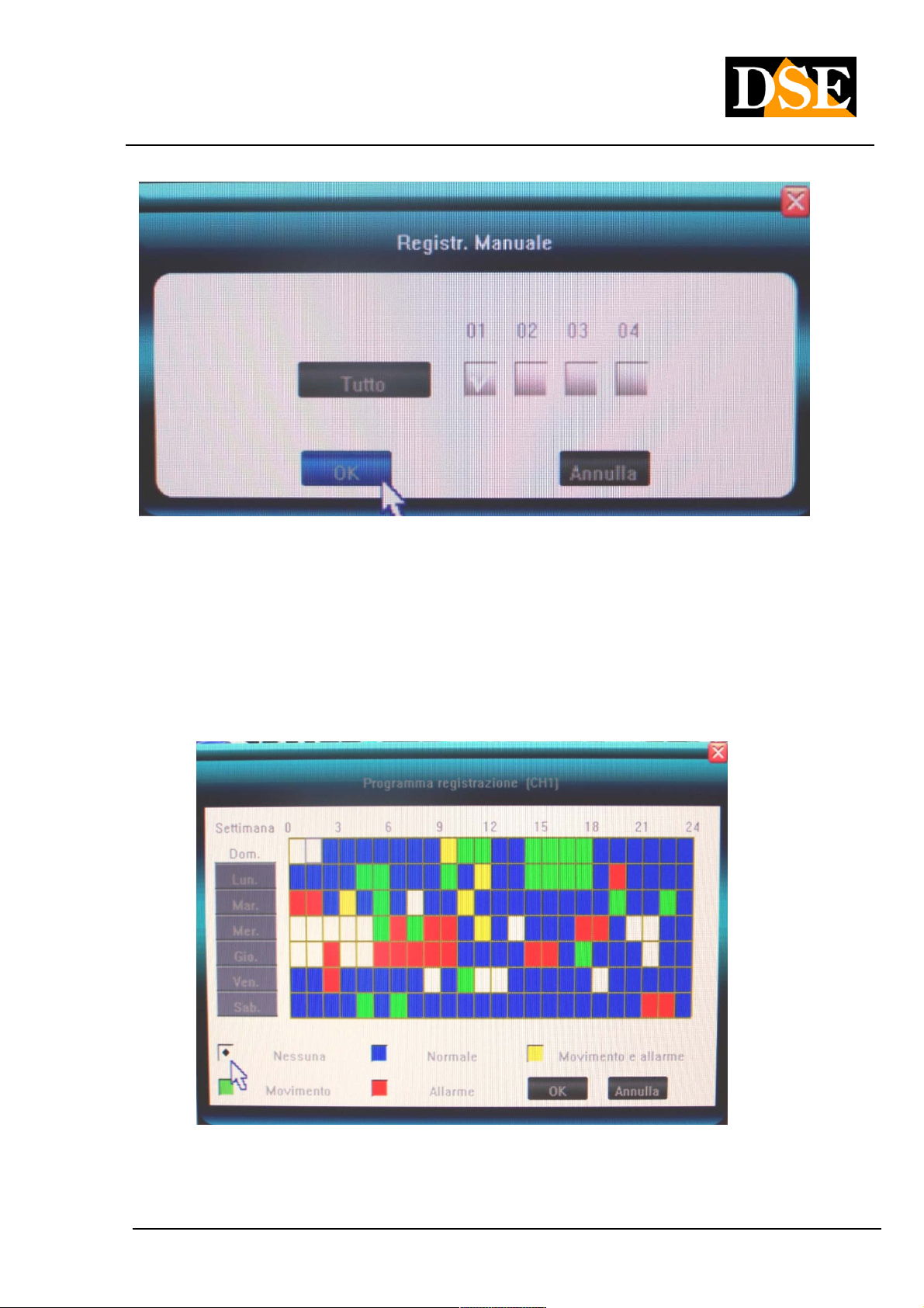
MANUAL RECORD -
Click the MANUAL RECORDING button in the toolbar and in the next window, choose which cameras enable
immediate recording. The recorded files
in manual recording are defined REGISTRATION
NORMAL.
DSE srl - ITALY - WWW.DSE.EU
Page 22
USER MANUAL
DIGITAL VIDEO DR-N4 / 8/16
Page: - 22 - Page: - 22 - Page: - 22 -
It 'also possible to start the manual recording with the REC button on the remote. To stop manual recording, press the
REC button
AUTOMATIC REGISTRATION -
E 'can program the DVR so that depending on the time and day of week registers in the preferred mode.
On the toolbar, choose the first icon on the left CONFIGURATION, then RECORDING, SELECT then press CAMERA
PROGRAM REGISTRATION
At the top it is shown the camera which is being programmed, if you want to edit it is necessary to cancel and select
another one. And 'the ALL option available for
DSE srl - ITALY - WWW.DSE.EU
Page 23
USER MANUAL
DIGITAL VIDEO DR-N4 / 8/16
Page: - 23 - Page: - 23 - Page: - 23 -
programs all cameras in the same way. The table shows the x-axis the hours of the day and ordered the weekdays.
Below there are the subscription options available:
WHITE: No registration
BLUE: Normal Continuous Recording
GREEN: Recording only on motion detection RED: Registration only upon activation of the external
alarm input YELLOW: Recording on motion detection and alarm input
Select one of the options in the lower register and then click on a weekly grid to program the DVR.
Note that in order to effectively use the recording with motion detection, you must set the detection masks in the setup
menu VIDEO (see below). To use the alarm inputs need to configure the ALARM section (see below)
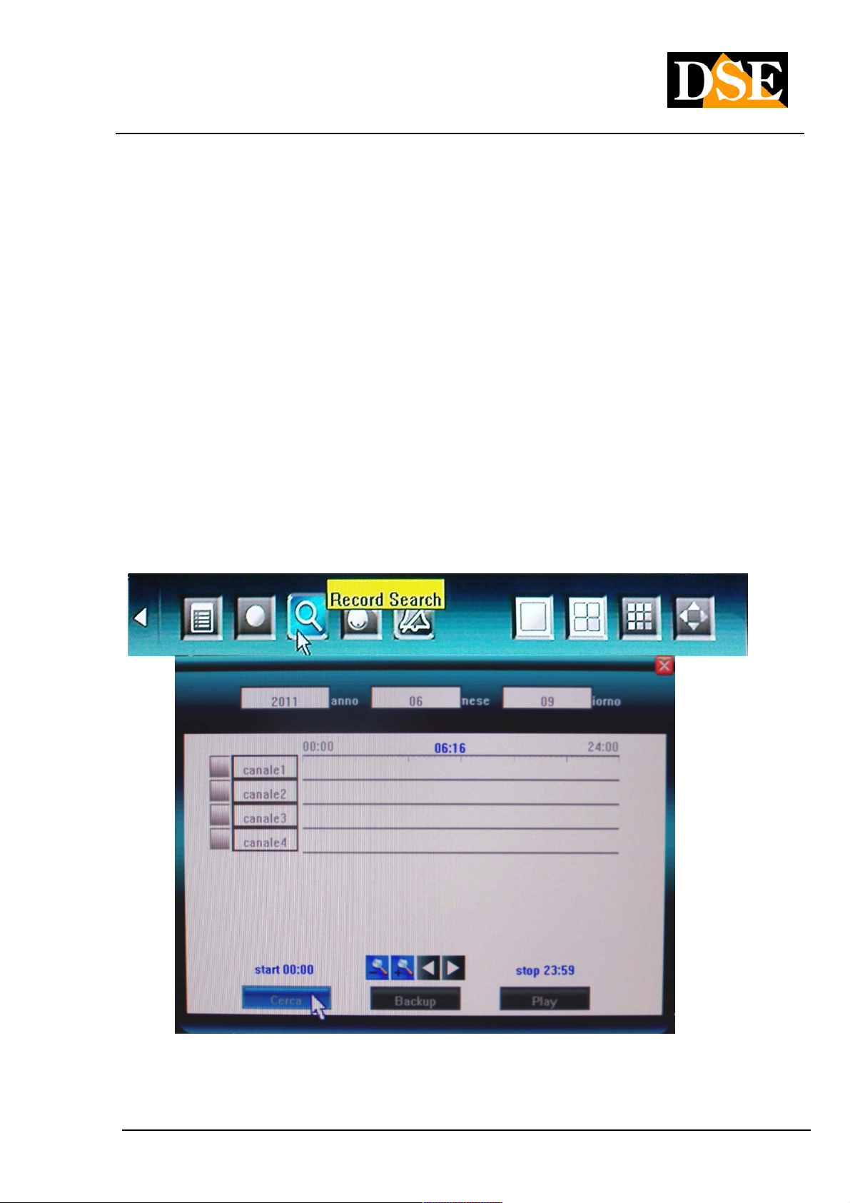
4.5 Playback 4.5 Playback
To review the recorded footage choose the search button in the toolbar
In the search window must stipulate the date the subject of research in the boxes at the top, then click the cameras of
interest. With the left mouse button
DSE srl - ITALY - WWW.DSE.EU
Page 24

USER MANUAL
DIGITAL VIDEO DR-N4 / 8/16
Page: - 24 - Page: - 24 - Page: - 24 -
enter the time limits in the timeline that represents the hours of the day (beginning and end). With the right mouse
button to delete the set limits. With the ZOOM + and - buttons you can change the scale of the timeline. If you control
the DVR from the remote control or keyboard to select the ZOOM icons on the screen and move with the arrows in the
time slot of interest, then press the MULTIVISION button 2 times to fix the beginning and the end of the corresponding
reproduction to the time interval displayed.
Once defined cameras and time interval press PLAY to start playback.
PLAYBACK CONTROLS
During playback the following commands are available:
: Rewind (8X, 16X) : Rewind (8X, 16X)
: Fast forward (1X speed, 8X, 16X, 1 / 2X and 1 / 4X). : Fast forward (1X speed, 8X, 16X, 1 / 2X and 1 / 4X).
: Pause : Pause
: Stop : Stop
: Go to the next frame : Go to the next frame
: View multivision : View multivision
: Defines the start and end of a clip to be saved
: Save on external support the clip defined by the previous button.
In playback, you can do it digital zoom of a detail drawing the interest frame with the mouse while holding down the left In playback, you can do it digital zoom of a detail drawing the interest frame with the mouse while holding down the left In playback, you can do it digital zoom of a detail drawing the interest frame with the mouse while holding down the left
mouse button.
4.6 Backup to external USB devices 4.6 Backup to external USB devices
DSE srl - ITALY - WWW.DSE.EU
Page 25

USER MANUAL
DIGITAL VIDEO DR-N4 / 8/16
Page: - 25 - Page: - 25 - Page: - 25 -
In the previous section, we saw how to search for and play back images. Once you selected interest period you can
press the BACK button to save the images to a storage medium connected to the rear USB port. You can connect USB
sticks and USB hard drives.
Pressing the Backup button the DVR will automatically detect the backup drive connected to the USB port.
E 'can select the video format in which to export movies. The following options are available:
• H.264 RAW
• MP4
• AVI
DSE srl - ITALY - WWW.DSE.EU
Page 26

USER MANUAL
DIGITAL VIDEO DR-N4 / 8/16
Page: - 26 - Page: - 26 - Page: - 26 -
Exporting a video clip
E 'can also export a video clip during playback directly.
Press
press it again to mark the end. Then press the save button
to immediately open the backup window and save the file.
while playing to select the beginning of the clip and
4.7 Play the backup files stored on external USB devices 4.7 Play the backup files stored on external USB devices
Once the movies saved on an external storage medium you can download them to a PC and play them.
AVI FILES - you reproduce with any player such as Windows Media Player FILES H.264 - They reproduce with a
player that supports this format, such as VLC, a free download from www.videolan.org.
MPEG4 FILES - They reproduce with a player that supports this format as MP4 Player included on the CD provided.
Alternatively you can use Windows Media Player after installing the codec WMP_MediaFilter.rar which is automatically
saved together with the files if you choose the export format MPEG4.
4.8 Control of Speed Dome cameras 4.8 Control of Speed Dome cameras
The DVRs allow to control the speed dome cameras connected to the rear serial port. To do this you need to choose a
single camera full screen and then press the PTZ button
It opens the PTZ control panel that allows the following commands:
DSE srl - ITALY - WWW.DSE.EU
Page 27

USER MANUAL
DIGITAL VIDEO DR-N4 / 8/16
Page: - 27 - Page: - 27 - Page: - 27 -
Close
speed
Zoom
Iris Fire
advanced
Shift
Accessories
Preset Cruise
Track
We recommend using a mouse in the control of speed dome cameras. In case of necessity, however, it is also possible
to control from the keypad or remote control by pressing one of the navigation buttons
, , , you can move the
camera in all directions.
At the top it is possible to adjust the rotation speed of the camera if the camera allows. If the camera settings allow it is
also possible to act on ZOOM, FOCUS and IRIS (Iris).
As an alternative to the navigation buttons can act directly with the mouse in the image while leaving the cursor from
the screen in the direction that you want to move the camera.
The advanced functions panel allows you to control auxiliary functions if supported by the camera (wiper, lighting etc.),
to set and recall PRESET, to set and start the automatic shift among multiple preset (CRUISE) to set up and start of
the paths, or patterns , custom (TRACK).
DSE srl - ITALY - WWW.DSE.EU
Page 28

USER MANUAL
DIGITAL VIDEO DR-N4 / 8/16
Page: - 28 - Page: - 28 - Page: - 28 -
5. Configuration 5. Configuration
Menu 5.1 CONFIGURATION
In the tool, click on the first icon of the CONFIGURATION MENU button to enter the menu where you
can set all the functional options of the DVR.
the CONFIGURATION MENU is divided into seven sections represented by the icons in the other in the window.
If you are using the mouse you can click directly on icons, or press the keys ◄► to move from one section to If you are using the mouse you can click directly on icons, or press the keys ◄► to move from one section to If you are using the mouse you can click directly on icons, or press the keys ◄► to move from one section to
another and then the keys ▲ ▼ to select the sub-function to be changed. another and then the keys ▲ ▼ to select the sub-function to be changed. another and then the keys ▲ ▼ to select the sub-function to be changed.
THE
Below are the programming tree that summarizes all of the options contained in the windows.
DSE srl - ITALY - WWW.DSE.EU
Page 29

USER MANUAL
DIGITAL VIDEO DR-N4 / 8/16
Page: - 29 - Page: - 29 - Page: - 29 -
DSE srl - ITALY - WWW.DSE.EU
Page 30

USER MANUAL
DIGITAL VIDEO DR-N4 / 8/16
Page: - 30 - Page: - 30 - Page: - 30 -
5.2 SYSTEM Menu
The system menu are:
LANGUAGE / LANGUAGE • to change the system language LANGUAGE / LANGUAGE • to change the system language LANGUAGE / LANGUAGE • to change the system language
VIDEO STANDARD • to select the appropriate video format cameras used (PAL / NTSC / SECAM) VIDEO STANDARD • to select the appropriate video format cameras used (PAL / NTSC / SECAM) VIDEO STANDARD • to select the appropriate video format cameras used (PAL / NTSC / SECAM)
VGA CONFIGURATION • to choose the proper resolution of the monitor connected to the VGA video (if any). The VGA CONFIGURATION • to choose the proper resolution of the monitor connected to the VGA video (if any). The VGA CONFIGURATION • to choose the proper resolution of the monitor connected to the VGA video (if any). The
resolution options are (800 x 600/1024 x 768/1280 X 1024/1440 X 900)
Beware if you accidentally set a resolution not supported by your monitor, you can press the key combination
ESC-CH2 keys on the keyboard repeatedly until you return to 800x600 resolution.
FORMAT TIME • to choose whether to display the time in 12 or 24 hours FORMAT TIME • to choose whether to display the time in 12 or 24 hours FORMAT TIME • to choose whether to display the time in 12 or 24 hours
SETTING TIME • to change the date and time. E 'need to stop recording to access this setting.SETTING TIME • to change the date and time. E 'need to stop recording to access this setting.SETTING TIME • to change the date and time. E 'need to stop recording to access this setting.
DST • to activate or deactivate summer and set deadlines now DST • to activate or deactivate summer and set deadlines now DST • to activate or deactivate summer and set deadlines now
HDD OVERWRITE • to enable or disable overwriting of files recorded on HDD. By activating the exhaustion of HDD OVERWRITE • to enable or disable overwriting of files recorded on HDD. By activating the exhaustion of HDD OVERWRITE • to enable or disable overwriting of files recorded on HDD. By activating the exhaustion of
physical space on the hard drive, the DVR will automatically delete and overwrite the oldest images.
ADD USER • The DVR can handle up to 7 people (6 + administrator). Acting here to customize the name of the ADD USER • The DVR can handle up to 7 people (6 + administrator). Acting here to customize the name of the ADD USER • The DVR can handle up to 7 people (6 + administrator). Acting here to customize the name of the
system users.
DSE srl - ITALY - WWW.DSE.EU
Page 31

USER MANUAL
DIGITAL VIDEO DR-N4 / 8/16
Page: - 31 - Page: - 31 - Page: - 31 -
DELETE USER • to delete a user from the system DELETE USER • to delete a user from the system DELETE USER • to delete a user from the system
MANAGING USERS ONLINE • Summarizes the users connected and the opportunity is to disconnect or reconnect MANAGING USERS ONLINE • Summarizes the users connected and the opportunity is to disconnect or reconnect MANAGING USERS ONLINE • Summarizes the users connected and the opportunity is to disconnect or reconnect
the system. In this section, the content is important because of the bandwidth consumed by each remote
connection.
DSE srl - ITALY - WWW.DSE.EU
Page 32

USER MANUAL
DIGITAL VIDEO DR-N4 / 8/16
Page: - 32 - Page: - 32 - Page: - 32 -
MANAGEMENT AUTHORITY ' • in this section for each access code it is possible to establish the authorization for MANAGEMENT AUTHORITY ' • in this section for each access code it is possible to establish the authorization for MANAGEMENT AUTHORITY ' • in this section for each access code it is possible to establish the authorization for
various control functions of the DVR. This section is accessible only by ADMIN code. All licenses are different
depending on whether they run locally or remotely.
CONFIGURATION PASSWORD • to change user passwords CONFIGURATION PASSWORD • to change user passwords CONFIGURATION PASSWORD • to change user passwords
DSE srl - ITALY - WWW.DSE.EU
Page 33

USER MANUAL
DIGITAL VIDEO DR-N4 / 8/16
Page: - 33 - Page: - 33 - Page: - 33 -
The system can manage an administrator password and user password 6.
The default password is admin: 888888 and User: 666666
Later he explains how to customize the user name and assign a level of access to the DVR functions.
FACTORY RESET PASSWORD
If after setting the access password you were to forget them there is a Hardware reset procedure to restore the
factory password.
DR-DR-N4 and N8: Open the DVR and locate on the motherboard the JP17 jumper next to the SATA connector. DR-DR-N4 and N8: Open the DVR and locate on the motherboard the JP17 jumper next to the SATA connector.
Bridging the jumper for a few seconds until the buzzer will sound a confirmation beep
DR-N16: Open the DVR and locate on the motherboard the JP15 jumper near the control panel. Bridging the DR-N16: Open the DVR and locate on the motherboard the JP15 jumper near the control panel. Bridging the
jumper for a few seconds until the buzzer will sound a confirmation beep
DVR ID NUMBER • Reserved for future implementations. It allows you to establish an identifier for the DVR.DVR ID NUMBER • Reserved for future implementations. It allows you to establish an identifier for the DVR.DVR ID NUMBER • Reserved for future implementations. It allows you to establish an identifier for the DVR.
G PREVIEW (CRUISE) • to set the image display mode when you start the SEQ polling. The first item allows you to G PREVIEW (CRUISE) • to set the image display mode when you start the SEQ polling. The first item allows you to G PREVIEW (CRUISE) • to set the image display mode when you start the SEQ polling. The first item allows you to
set the dwell time on the screen of each screen,
the second
how many cameras to show at all (1/4 screen), and the third which cameras to scan.
SPECIAL MENU • enables automatic logout from the DVR in the absence of operations after 30 seconds, 1 minute SPECIAL MENU • enables automatic logout from the DVR in the absence of operations after 30 seconds, 1 minute SPECIAL MENU • enables automatic logout from the DVR in the absence of operations after 30 seconds, 1 minute
or 5 minutes. This option is to be enabled if you want to allow viewing of the cameras only to authorized
personnel.
SETTING LOCK CHANNEL • The administrator can make sure that the normal user codes can not see the images SETTING LOCK CHANNEL • The administrator can make sure that the normal user codes can not see the images SETTING LOCK CHANNEL • The administrator can make sure that the normal user codes can not see the images
of one or more cameras
SPOT CONFIGURATION • This feature is only available on the DR-N16 model is used to establish the display SPOT CONFIGURATION • This feature is only available on the DR-N16 model is used to establish the display SPOT CONFIGURATION • This feature is only available on the DR-N16 model is used to establish the display
visible in sequence from the
DSE srl - ITALY - WWW.DSE.EU
Page 34

USER MANUAL
DIGITAL VIDEO DR-N4 / 8/16
Page: - 34 - Page: - 34 - Page: - 34 -
CALL OUT ( DR-N16 only). E 'can be programmed always a full schemro camera or a scanning between multiple CALL OUT ( DR-N16 only). E 'can be programmed always a full schemro camera or a scanning between multiple CALL OUT ( DR-N16 only). E 'can be programmed always a full schemro camera or a scanning between multiple
cameras with a choice of programmable dwell time.
WAY MANAGEMENT RESOURCES (DR-N8 only) • This section allows to distribute the DVR resources in a WAY MANAGEMENT RESOURCES (DR-N8 only) • This section allows to distribute the DVR resources in a WAY MANAGEMENT RESOURCES (DR-N8 only) • This section allows to distribute the DVR resources in a WAY MANAGEMENT RESOURCES (DR-N8 only) • This section allows to distribute the DVR resources in a
different way between the channels depending of their importance. in order to choose the resolution and frame
rate that best suits your recording needs. The panel offers several pre-configured settings with different resolution
for different channels
Below are the available options:
DR-N8
8 D1 channel 8 channel D1 encoding D1 + 8
channel playback
8 channel CIF 8 channel CIF encoding + 8
channel CIF Playback
8 HD1 channel 8 + 8 encoding HD1 HD1 channel
playback
1 channel D1 + 7
channel CIF
1 channel D1 encoding + 7 + 1
channel CIF encoding D1 channel
playback
Each channel can record / play the
maximum PAL: 4 fps (D1), 12fps
(HD1), 25fps (CIF)
Each channel can record / play
the maximum PAL: 25fps CIF, do
not set D1 / HD1
Each channel can record / play
the maximum PAL: 12.5Fps
(HD1), 25fps (CIF), do not set D1
PAL:
recording / playback 25fps (D1, HD1,
CIF)
only one channel playback
Select a channel for maximum
30Fps or 25 fps D1 / HD1,
others are CIF
2 + HD1 channel 6
channel CIF
2 channel encoding HD1 + 6 + 2
channel CIF encoding HD1 channel
playback
DSE srl - ITALY - WWW.DSE.EU
PAL:
recording / playback 25fps (HD1, CIF)
You do not set D1
Playing only 2 channels of your
choice
Select 2 channels for
maximum 30Fps or 25fps
HD1, others are CIF
Page 35

USER MANUAL
DIGITAL VIDEO DR-N4 / 8/16
Page: - 35 - Page: - 35 - Page: - 35 -
5.3 RECORDING Menu
The REGISTRATION menu is divided into SIMPLE CONFIGURATION and ADVANCED CONFIGURATION.
EASY CONFIGURATION In include:
VIDEO CH • This box is used to select the channel on which to apply the recording settings, you can select only VIDEO CH • This box is used to select the channel on which to apply the recording settings, you can select only VIDEO CH • This box is used to select the channel on which to apply the recording settings, you can select only
one channel at a time or choose the ALL option to program all the cameras in the same way.
PROGRAM REGISTRATION • to activate the timer recording. The timer recording settings enable the PROGRAM REGISTRATION • to activate the timer recording. The timer recording settings enable the PROGRAM REGISTRATION • to activate the timer recording. The timer recording settings enable the
administrator to define when and how to record based on the time and day of the week. See detail in the previous
chapter.
QUALITY 'REGISTRATION • Possibility of QUALITY 'REGISTRATION • Possibility of QUALITY 'REGISTRATION • Possibility of Sets the quality of
recording of the selected camera. A higher quality corresponds less video compression and greater bandwidth
occupied. You can choose different options including: LOW (384 Kbps), MEDIUM (512Kbps), HIGH (640 Kbps),
BEST (768 Kbps), USER-DEFINED, in this last option the user can set the bitrate to his liking (maximum 2048).
FRAME OF RECORD RATE • It needs to set the FRAME RATE in the recording. You can choose between 1, 3, 6, FRAME OF RECORD RATE • It needs to set the FRAME RATE in the recording. You can choose between 1, 3, 6, FRAME OF RECORD RATE • It needs to set the FRAME RATE in the recording. You can choose between 1, 3, 6,
12, FULL, USER-DEFINED where the user can set the frame rate to your liking (maximum 25)
SOURCE REGISTRATION • to choose whether to record only VIDEO or AUDIO and VIDEO at the same time SOURCE REGISTRATION • to choose whether to record only VIDEO or AUDIO and VIDEO at the same time SOURCE REGISTRATION • to choose whether to record only VIDEO or AUDIO and VIDEO at the same time
CONFIGURATION OSD • to choose whether to superimpose registered in the name of the camera file (CAMERA CONFIGURATION OSD • to choose whether to superimpose registered in the name of the camera file (CAMERA CONFIGURATION OSD • to choose whether to superimpose registered in the name of the camera file (CAMERA
NAME), the date and time (timestamp), both, or nothing.
RECORDING RESOLUTION • to select which recording resolution to use. Three options available: CIF (352x288), RECORDING RESOLUTION • to select which recording resolution to use. Three options available: CIF (352x288), RECORDING RESOLUTION • to select which recording resolution to use. Three options available: CIF (352x288),
HALF-D1 (704x288), D1 (704x576). A higher resolution is more occupied space on the hard disk and a maggiora
occupied bandwidth network.
DSE srl - ITALY - WWW.DSE.EU
Page 36

USER MANUAL
DIGITAL VIDEO DR-N4 / 8/16
Page: - 36 - Page: - 36 - Page: - 36 -
ADVANCED CONFIGURATION In include:
SUB CODE • The DVR feature of DUAL STREAMING function for which they are able to send streaming different, SUB CODE • The DVR feature of DUAL STREAMING function for which they are able to send streaming different, SUB CODE • The DVR feature of DUAL STREAMING function for which they are able to send streaming different,
with different bandwidth to different devices, even when connected simultaneously. Enabling the SUB CODE
option you set the FRAME RATE and BITRATE to use in viewing from mobile devices where available is often
limited bandwidth. To set the SUB CODE choose ON, press
set the frame rate and bit rate to be used in connection with insufficient bandwidth.
Note that for each camera it is possible to set a sub different queues according to the importance thereof.
, is
5.4 Video Menu
The video menu is divided into SIMPLE CONFIGURATION and ADVANCED CONFIGURATION.
EASY CONFIGURATION In include:
DSE srl - ITALY - WWW.DSE.EU
Page 37

USER MANUAL
DIGITAL VIDEO DR-N4 / 8/16
Page: - 37 - Page: - 37 - Page: - 37 -
CAMERA CH • Select the channel to apply the video settings, you can select one channel at a time or the ALL CAMERA CH • Select the channel to apply the video settings, you can select one channel at a time or the ALL CAMERA CH • Select the channel to apply the video settings, you can select one channel at a time or the ALL
option that configures all channels in the same way.
PTZ PROTOCOL • Sets the PTZ protocol to be used for controlling the speed dome cameras installed. Among the PTZ PROTOCOL • Sets the PTZ protocol to be used for controlling the speed dome cameras installed. Among the PTZ PROTOCOL • Sets the PTZ protocol to be used for controlling the speed dome cameras installed. Among the
protocols are PELCO D for use with SD series speed dome cameras and protocols of the main PHILIP builders,
PANASONIC, SAMSUNG, VTS, Yaan, YBOER, SYYT, VIDO, TIANDY, JY2000, TD500, CLT-618
PTZ BAUD RATE • Sets the speed of the Protocol (from 1200 to 9600) PTZ BAUD RATE • Sets the speed of the Protocol (from 1200 to 9600) PTZ BAUD RATE • Sets the speed of the Protocol (from 1200 to 9600)
PTZ ID • Sets the speed of the dome camera ID (0 to 255) Before configuring the command of the speed dome in PTZ ID • Sets the speed of the dome camera ID (0 to 255) Before configuring the command of the speed dome in PTZ ID • Sets the speed of the dome camera ID (0 to 255) Before configuring the command of the speed dome in
the DVR verify the settings of the camera carefully (protocol, speed, address) in order to set them consistently in
the DVR, otherwise the camera will not respond to commands.
CONFIGURATION COLORS • click CONFIGURATION COLORS • click CONFIGURATION COLORS • click
GLOSS / CONTRAST / HUE / SATURATION (1 to 16). To exit the settings, click ESC or right-click
MOTION DETECTION • in this section the user sets the sensitivity and the area on which to enable logging in MOTION DETECTION • in this section the user sets the sensitivity and the area on which to enable logging in MOTION DETECTION • in this section the user sets the sensitivity and the area on which to enable logging in
MOTION DETECTION. For recording MOTION DETECTION we intend to start recording only when the system
detects movement or a change in the image. The first thing to do is to set the sensitivity (disable, higher
sensitivity, normal sensitivity, low sensitivity), made this click
enable DETECTION MOVEMENT (AREA) and the enable period of the motion detection.
to set the values of
to set the area on which
Click MOTION DETECTION ZONE. the monitor is subdivided into many small squares that form a real grid, if the
background is the BLUE MOTION is active, when in fact the background is transparent the MOTION DETECTION
is not active. To define the detection area select the grid square with the navigation arrows and press
or ENTER to change the or ENTER to change the
riqudro status.
The selection of masks is done very comfortably with the mouse by dragging the arrow while pressing the left
button.
Once you completed the selection of the detection mask click with the right mouse button or press the ESC key to
exit.
DSE srl - ITALY - WWW.DSE.EU
Page 38

USER MANUAL
DIGITAL VIDEO DR-N4 / 8/16
Page: - 38 - Page: - 38 - Page: - 38 -
Click MOTION DETECTION PROGRAM if you want to make active motion only at certain times depending on the
day of the week.
MOSAIC • This function is used to activate and define any of the privacy mask (ON / OFF) used to mask a MOSAIC • This function is used to activate and define any of the privacy mask (ON / OFF) used to mask a MOSAIC • This function is used to activate and define any of the privacy mask (ON / OFF) used to mask a
particular you do not want to see during playback so that you do not want to record as a rule to protect personal
privacy. In this section by clicking on
It proposes a subdivision grid similar to the motion detection, where it is possible to set the area to hide acting
directly on the image with the left mouse button (right button to delete the created mask). With the keyboard or
remote control using the arrow keys and the keys
, ENTER
to create the mask, and the ESC key to delete the created mask. E 'can create up to four masks for each
camera.
Yes
ADVANCED CONFIGURATION In include:
MANAGEMENT MOVEMENT • in this section you can establish the following a motion detection system behavior. MANAGEMENT MOVEMENT • in this section you can establish the following a motion detection system behavior. MANAGEMENT MOVEMENT • in this section you can establish the following a motion detection system behavior.
If you check the box RECORDING DVR in case of motion detection will start recording (select the cameras that
follow this rule); if you check ALARM ZOOM OUT the system will display the full screen camera that has detected
a movement (select the cameras that follow this rule); if you check ALARM OUT the output is enabled
DSE srl - ITALY - WWW.DSE.EU
Page 39

USER MANUAL
DIGITAL VIDEO DR-N4 / 8/16
Page: - 39 - Page: - 39 - Page: - 39 -
alarm; BUZZER if you check the DVR will trigger the integrated acoustic signal; if you check the UPLOAD DVR
will send a warning icon to the IE browser of all PCs connected to the DVR; EMAIL if you check the system will
send an email to the email address set in the NET / EMAIL SETUP section
VIDEO LOSS TREATMENT • in this section you can be established in the case of THE VIDEO SIGNAL LOSS VIDEO LOSS TREATMENT • in this section you can be established in the case of THE VIDEO SIGNAL LOSS VIDEO LOSS TREATMENT • in this section you can be established in the case of THE VIDEO SIGNAL LOSS VIDEO LOSS TREATMENT • in this section you can be established in the case of THE VIDEO SIGNAL LOSS
(ALARM OUT behavior of the system, BUZZER, UPLOAD, EMAIL). Checking the boxes the system will activate
the corresponding function in case of video loss of any camera.
CHANNEL NAME SETTING • in this section it is possible to name the selected camera CHANNEL NAME SETTING • in this section it is possible to name the selected camera CHANNEL NAME SETTING • in this section it is possible to name the selected camera CHANNEL NAME SETTING • in this section it is possible to name the selected camera
OFFSET ROOM • spontandola to adjust the image display left or right OFFSET ROOM • spontandola to adjust the image display left or right OFFSET ROOM • spontandola to adjust the image display left or right
5.5 NETWORK menu (NET)
In .NET menu the user sets the parameters concerning the network connection for remote control of the DVR.
DSE srl - ITALY - WWW.DSE.EU
Page 40

USER MANUAL
DIGITAL VIDEO DR-N4 / 8/16
Page: - 40 - Page: - 40 - Page: - 40 -
NETWORK • providing for the administration of network addresses. You can choose between STATIC IP, to give NETWORK • providing for the administration of network addresses. You can choose between STATIC IP, to give NETWORK • providing for the administration of network addresses. You can choose between STATIC IP, to give
the DVR a fixed IP address, and DHCP to make sure that the DVR functions with IP addresses automatically
assigned by a DHCP server.
IP ADDRESS • Enter the IP address if you chose to assign a static IP address to the DVR IP ADDRESS • Enter the IP address if you chose to assign a static IP address to the DVR IP ADDRESS • Enter the IP address if you chose to assign a static IP address to the DVR
SUBNETMASK • enter the subnet mask of the network (must be provided only if you chose static IP address) SUBNETMASK • enter the subnet mask of the network (must be provided only if you chose static IP address) SUBNETMASK • enter the subnet mask of the network (must be provided only if you chose static IP address)
GATEWAY • enter the network gateway (must be provided only if you chose static IP address) GATEWAY • enter the network gateway (must be provided only if you chose static IP address) GATEWAY • enter the network gateway (must be provided only if you chose static IP address)
HTTP PORT • Communication port used for browser via http dialogue (default: 80) HTTP PORT • Communication port used for browser via http dialogue (default: 80) HTTP PORT • Communication port used for browser via http dialogue (default: 80)
PORT COMMAND • Communication port used for remote control of the DVR (default: 5050) PORT COMMAND • Communication port used for remote control of the DVR (default: 5050) PORT COMMAND • Communication port used for remote control of the DVR (default: 5050)
DOOR MEDIA • Communication port used to stream video (default 6050) DOOR MEDIA • Communication port used to stream video (default 6050) DOOR MEDIA • Communication port used to stream video (default 6050)
NOTE: If the remote connection is made via a router is necessary that the door just listed (default: 80, 5050,
6050) are configured in the section PORT FORWRDING the router so as to be directional to the internal IP
address corresponding to the DVR. For the mobile devices must also direct the 7050 port
PPPoE SETTING • if the camera is not connected to a network but directly to an ADSL modem must enable PPPoE SETTING • if the camera is not connected to a network but directly to an ADSL modem must enable PPPoE SETTING • if the camera is not connected to a network but directly to an ADSL modem must enable
PPPoE and enter the login information to connect to the Internet from the provider. Clicking on a window like this
that allows us to enter data related to PPPoE
IP PPPoE • Show the 'IP address PPPoE IP PPPoE • Show the 'IP address PPPoE IP PPPoE • Show the 'IP address PPPoE
ADDRESS DNS • Show the DNS (Domain Name Server) ADDRESS DNS • Show the DNS (Domain Name Server) ADDRESS DNS • Show the DNS (Domain Name Server)
DDNS • To connect through the Internet is highly advisable to have a fixed IP address so that you always know the DDNS • To connect through the Internet is highly advisable to have a fixed IP address so that you always know the DDNS • To connect through the Internet is highly advisable to have a fixed IP address so that you always know the
exact address to connect. If it can not get from your provider, all of the range DVR support DDNS service
(Dynamic DNS) that allow you to constantly monitor the machine's IP address. These services,
DSE srl - ITALY - WWW.DSE.EU
Page 41

USER MANUAL
DIGITAL VIDEO DR-N4 / 8/16
Page: - 41 - Page: - 41 - Page: - 41 -
Also available for free, provide the user with a domain name that you type into your browser. The DDNS provider
redirects communication to the IP address that the DVR has at that moment. Pressing
It will appear on a screen
window like this that allows us to enter the data relative to the DDNS provider
The DR series DVR support leading DDNS services available on the net:
www.easydns.com
www.justlinux.com
www.dyns.cx www.hn.org
www.zoneedit.com
members.3322.org
members.dyndns.org
myq-see.com
www.easterndns.com ddo.jp
www.no-ip.com
www.ez-ip.net
www.penguinpowered.com
members.dhs.org update.ods.org
cgi.tzo.com
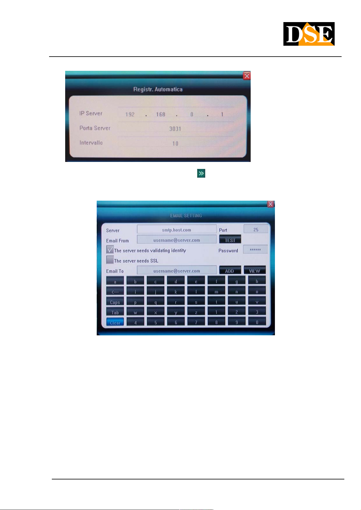
AUTOMATIC REGISTRATION • The DVR can be configured to automatically register on a software CMS (Central AUTOMATIC REGISTRATION • The DVR can be configured to automatically register on a software CMS (Central AUTOMATIC REGISTRATION • The DVR can be configured to automatically register on a software CMS (Central
Monitoring Station), by entering the IP address of the SERVER, PORT SERVER and Interval in seconds to wait
between an unsuccessful attempt and the following connection.
DSE srl - ITALY - WWW.DSE.EU
Page 42
USER MANUAL
DIGITAL VIDEO DR-N4 / 8/16
Page: - 42 - Page: - 42 - Page: - 42 -
EMAIL SETUP • click EMAIL SETUP • click EMAIL SETUP • click
EMAIL and to access the following window that allows you to set parameters for sending alert emails.
The DVR DR series are able to send e-mails in different alarm conditions such as motion detection, alarm input
etc. in In this section, the administrator can set up e-mail transmission parameters. Consider that most Internet
providers insert anti-spam systems that can make it impossible to send e-mail without using the common mail
clients, this could result in a failure of the function, consult your ISP about it.
to enter the configuration
Enter the address of the SMTP server and port as instructed by your ISP. In the field EMAIL FROM enter the
email address you want to appear as the sender. If the SMTP server requires authentication check the box and
enter the password.
In the last box you enter the email address of the recipient and clicking Agg. It is added to the recipient list that
you can view by clicking VIEW. The TEST button is available to test the features of the connection.
MOBILE DOOR • used to set the network port to be used for connecting mobile phone or PDA. By default the port MOBILE DOOR • used to set the network port to be used for connecting mobile phone or PDA. By default the port MOBILE DOOR • used to set the network port to be used for connecting mobile phone or PDA. By default the port
is set 705 0. is set 705 0. is set 705 0.
DSE srl - ITALY - WWW.DSE.EU
Page 43

USER MANUAL
DIGITAL VIDEO DR-N4 / 8/16
Page: - 43 - Page: - 43 - Page: - 43 -
UPnP • activate this feature to make sure that in "Windows Explorer" resources you can automatically detect the DVR UPnP • activate this feature to make sure that in "Windows Explorer" resources you can automatically detect the DVR UPnP • activate this feature to make sure that in "Windows Explorer" resources you can automatically detect the DVR
from the network resources. In the UPnP protocol enabling DR series video recorders also allows you to map the
router ports for remote access via the Internet automatically with no need to do it manually in its internal
configuration. In order to use this feature may be that the router supports UPnP.
Pressing
mapping the 4 ports used in the remote control of the DVR. This may take a few seconds, at the end you will see
a screen like the following, which confirms the correct directing of the doors.
DVR starts a communication with the router and try to
If the MAPPING STATUS column does not appear the message SUCCESSFUL this means the router has
refused education for example, because its configuration is down this instruction directing different for the required
port. In this case it is possible to press the REMAP key to retry the automatic configuration. If this procedure does
not go to fruition mapping will be done manually by accessing the internal configuration of the router.
FTP SETTINGS • to set the settings of the FTP file transfer protocol FTP SETTINGS • to set the settings of the FTP file transfer protocol FTP SETTINGS • to set the settings of the FTP file transfer protocol
ACCESS IP • This section is used to allow or deny remote access to specific IP addresses by creating black / white ACCESS IP • This section is used to allow or deny remote access to specific IP addresses by creating black / white ACCESS IP • This section is used to allow or deny remote access to specific IP addresses by creating black / white
list. If you do not want to discriminate IP addresses that can be connected to keep this option disabled.
TIME SYNC • This section allows you to automatically synchronize your DVR time with internet NTP server. E 'can TIME SYNC • This section allows you to automatically synchronize your DVR time with internet NTP server. E 'can TIME SYNC • This section allows you to automatically synchronize your DVR time with internet NTP server. E 'can
set the server to use, and the sync interval
SPECIAL DDNS • Available only in the DR-N16 . It allows the use of a serviceSPECIAL DDNS • Available only in the DR-N16 . It allows the use of a serviceSPECIAL DDNS • Available only in the DR-N16 . It allows the use of a serviceSPECIAL DDNS • Available only in the DR-N16 . It allows the use of a service
DSE srl - ITALY - WWW.DSE.EU
Page 44

USER MANUAL
DIGITAL VIDEO DR-N4 / 8/16
Page: - 44 - Page: - 44 - Page: - 44 -
DDNS added. Pressing The setup window appears
service
5.6 ALARM Menu
In this section you program the options for managing the alarms generated by external inputs on the back of the
DVR
ALARM INPUT CH • this box is used to select the alarm input to be programmed, you can select only one input at ALARM INPUT CH • this box is used to select the alarm input to be programmed, you can select only one input at ALARM INPUT CH • this box is used to select the alarm input to be programmed, you can select only one input at
a time or choose the ALL option, to program all the inputs in the same way
TYPE ALARM INPUT • you can choose between NO (normally open) and NC (normally closed). This option TYPE ALARM INPUT • you can choose between NO (normally open) and NC (normally closed). This option TYPE ALARM INPUT • you can choose between NO (normally open) and NC (normally closed). This option
defines the electrical operation
input and allows you to connect inputs both normally open (NO) and normally closed (NC).
EVENT MANAGEMENT • click EVENT MANAGEMENT • click EVENT MANAGEMENT • click
events
to access the Management Window
DSE srl - ITALY - WWW.DSE.EU
Page 45

USER MANUAL
DIGITAL VIDEO DR-N4 / 8/16
Page: - 45 - Page: - 45 - Page: - 45 -
In this window you can specify what actions should make the DVR to the occurrence of an alarm input simply by
checking the appropriate boxes. Are available
The following alarm action: Start
refusal- Preset speed dome cameras - Pop-up alarm camera - Alarm activation output - Buzzer - Notification of
connected clients - Email Sending. - Upload via FTP
ALARM CONFIGURATION • This option allows to enable the detection of alarms only at certain times of the day or ALARM CONFIGURATION • This option allows to enable the detection of alarms only at certain times of the day or ALARM CONFIGURATION • This option allows to enable the detection of alarms only at certain times of the day or
week. Click on
to access the configuration table.
The table presents the x-axis the hours of the day and ordered the weekdays. If the box is RED alarm detection is
activated while if the alarm is turned off is WHITE color.
ALARM ZOOM • This option sets the amount of time a full screen of the camera in alarm if it is activated the zoom ALARM ZOOM • This option sets the amount of time a full screen of the camera in alarm if it is activated the zoom ALARM ZOOM • This option sets the amount of time a full screen of the camera in alarm if it is activated the zoom
function alarm (pop-up) and for motion for alarm input ..
EXCEPT FOR ACTION • clicking EXCEPT FOR ACTION • clicking EXCEPT FOR ACTION • clicking
DVR behavior in case of exceptional events: HDD full, network disconnected and conflicting IP addresses. You
'can turn out, buzzer and also send email and FTP upload.
It enters a screen to manage
DSE srl - ITALY - WWW.DSE.EU
Page 46

USER MANUAL
DIGITAL VIDEO DR-N4 / 8/16
Page: - 46 - Page: - 46 - Page: - 46 -
Menu 5.7 MANAGEMENT
VIEW LOG • It accesses to the memory of the events (LOG) of the DVR that the historical memory of chronological VIEW LOG • It accesses to the memory of the events (LOG) of the DVR that the historical memory of chronological VIEW LOG • It accesses to the memory of the events (LOG) of the DVR that the historical memory of chronological
DVR. The memory contains the last 3000 events.DVR. The memory contains the last 3000 events.
In the selection window at the top choose the type of event to search for. There are 4 types of events can be
selected: ALL, ALARM, EXCEPTION (exceptional event eg. Video lack, failure, etc.), OPERATION (operator
operations such as ignition, configurations, etc.). After choosing the event and set the time interval in which to
search click Search to
DSE srl - ITALY - WWW.DSE.EU
Page 47

USER MANUAL
DIGITAL VIDEO DR-N4 / 8/16
Page: - 47 - Page: - 47 - Page: - 47 -
display the events of the desired list.
UPGRADE • DVR supports upgrading the internal firmware can be via USB or remotely via IE browser. This UPGRADE • DVR supports upgrading the internal firmware can be via USB or remotely via IE browser. This UPGRADE • DVR supports upgrading the internal firmware can be via USB or remotely via IE browser. This
configuration menu button is used to update the firmware from the USB port. Copy the update file to a USB stick
in the root directory (not a subfolder) and connect the key to the rear USB port before starting the procedure.
HDD MANAGEMENT • It allows formatting the hard disk. See chapterHDD MANAGEMENT • It allows formatting the hard disk. See chapterHDD MANAGEMENT • It allows formatting the hard disk. See chapter
4.3
USB MANAGEMENT • allows the formatting of the storage device connected to the USB socket of the DVR USB MANAGEMENT • allows the formatting of the storage device connected to the USB socket of the DVR USB MANAGEMENT • allows the formatting of the storage device connected to the USB socket of the DVR
PARAMETER EXPORT • It transfers the programming of the DVR to the device connected to the USB jack PARAMETER EXPORT • It transfers the programming of the DVR to the device connected to the USB jack PARAMETER EXPORT • It transfers the programming of the DVR to the device connected to the USB jack
IMPORT PARAMETER • It transfers the programming of the DVR from the device connected to the USB jack to IMPORT PARAMETER • It transfers the programming of the DVR from the device connected to the USB jack to IMPORT PARAMETER • It transfers the programming of the DVR from the device connected to the USB jack to
the DVR
AUTO CARE • to set the scheduled restart of the DVR (daily, weekly, once) AUTO CARE • to set the scheduled restart of the DVR (daily, weekly, once) AUTO CARE • to set the scheduled restart of the DVR (daily, weekly, once)
CAPACITY 'HDD • shows the total space and free space on the Hard Disk CAPACITY 'HDD • shows the total space and free space on the Hard Disk CAPACITY 'HDD • shows the total space and free space on the Hard Disk
HARDWARE VERSION • Version motherboard DVR HARDWARE VERSION • Version motherboard DVR HARDWARE VERSION • Version motherboard DVR
SOFTWARE VERSION • version of the DVR firmware SOFTWARE VERSION • version of the DVR firmware SOFTWARE VERSION • version of the DVR firmware
DATE SOFTWARE DISTRIBUTION • date of the firmware release installed DATE SOFTWARE DISTRIBUTION • date of the firmware release installed DATE SOFTWARE DISTRIBUTION • date of the firmware release installed
MAC ADDRESS • MAC address of DVR MAC ADDRESS • MAC address of DVR MAC ADDRESS • MAC address of DVR
DVR ID • DVR name DVR ID • DVR name DVR ID • DVR name
DSE srl - ITALY - WWW.DSE.EU
Page 48

USER MANUAL
DIGITAL VIDEO DR-N4 / 8/16
Page: - 48 - Page: - 48 - Page: - 48 -
5.8 SAVE menu
In this section you can leave the programming menu and save your changes. The available options are:
SAVE AND EXIT • to exit the menu and save the changed settings SAVE AND EXIT • to exit the menu and save the changed settings SAVE AND EXIT • to exit the menu and save the changed settings
GO OUT • to exit the menu without saving changes GO OUT • to exit the menu without saving changes GO OUT • to exit the menu without saving changes
RESTORE DEFAULT • to reset to the factory settings of the DVR. RESTORE DEFAULT • to reset to the factory settings of the DVR. RESTORE DEFAULT • to reset to the factory settings of the DVR.
LOGOUT • to make the LOGOUT. Once the password LOGOUT will need to re-enter again to return to the LOGOUT • to make the LOGOUT. Once the password LOGOUT will need to re-enter again to return to the LOGOUT • to make the LOGOUT. Once the password LOGOUT will need to re-enter again to return to the
programming menu.
DSE srl - ITALY - WWW.DSE.EU
Page 49

USER MANUAL
DIGITAL VIDEO DR-N4 / 8/16
Page: - 49 - Page: - 49 - Page: - 49 -
6. Remote connection with IE browser
The DVR DR series are capable of being controlled remotely via network or Internet using PC or mobile devices like
mobile phones, iPhone / iPad, PDA etc. To access the DVR by using a network PC is not necessary to install any
software because you are using the IE browser. E 'can also be accessed by other browsers such as it will be described
later.
6.1 Enabling the execution of ActiveX
Internet Explorer has security settings that may prevent connection to the DVR. Before making the connections
necessary to enable the execution of ActiveX not marked as safe. In Internet Explorer, select TOOLS / INTERNET
OPTIONS
In the folder PROTECTION choose the area of interest (Internet or local network) and click CUSTOM LEVEL. Enable
all items for the download to run ActiveX especially those NOT marked as safe.
6.2 Disable user control of Windows7 and Vista (UAC)
And 'advisable to disable the user control in Windows 7 and Windows Vista
• Click START / CONTROL PANEL
• Select USER ACCOUNTS
• Select OFF USER ACCOUNT CONTROL
6.3 Web browser / Home Screen
The most complete remote access is made with the Internet Explorer browser. To connect to the DVR with Internet
Explorer browser enter the IP address of the DVR in the address bar and press Enter to access the LOGIN DVR box.
On first access, depending on your browser security settings you can
DSE srl - ITALY - WWW.DSE.EU
Page 50

USER MANUAL
DIGITAL VIDEO DR-N4 / 8/16
Page: - 50 - Page: - 50 - Page: - 50 -
be prompted for permission to install the activeX component. Authorize installation and execution of the add-ons. If the
installation does not complete successfully, review the browser's security settings (section 6.1) allow all the options of
ActiveX components. If all components will be installed correctly you will see the login screen:
The password to use the factory is Admin ( with a capital A) PW: 888888 The password to use the factory is Admin ( with a capital A) PW: 888888 The password to use the factory is Admin ( with a capital A) PW: 888888 The password to use the factory is Admin ( with a capital A) PW: 888888
Select AUTOMATION TO OPEN PREVIEW to immediately view the cameras, alternatively, once you click LOGIN
OPEN ALL in the lower left to see all the cameras installed in the DVR.
DSE srl - ITALY - WWW.DSE.EU
Page 51

USER MANUAL
DIGITAL VIDEO DR-N4 / 8/16
Page: - 51 - Page: - 51 - Page: - 51 -
1 camera display window 2 Camera status 3 image 1 camera display window 2 Camera status 3 image 1 camera display window 2 Camera status 3 image 1 camera display window 2 Camera status 3 image
adjustment tools
: Adjusting image contrast. : Adjusting image contrast.
: Adjusting the brightness of the image. : Adjusting the brightness of the image.
: Start / stop audio. The icon turns green qundo audio is active.: Start / stop audio. The icon turns green qundo audio is active.
: Start / stop recording. The icon turns green while recording.: Start / stop recording. The icon turns green while recording.
: Click to save individual frames. : Click to save individual frames.
: ends the camera view. : ends the camera view.
: Clicking this icon you can zoom by drawing a riqudro with your mouse in the image.
Click on
recorded and the captured frames. 4 Camera display turned off. 5 List of all channels on the DVR. recorded and the captured frames. 4 Camera display turned off. 5 List of all channels on the DVR. recorded and the captured frames. 4 Camera display turned off. 5 List of all channels on the DVR.
As an alternative to OPEN ALL command is
You can start playing inidvidualmente cameras by double-clicking in this area. 6 Toolbar You can start playing inidvidualmente cameras by double-clicking in this area. 6 Toolbar
to set the file storage directory
DSE srl - ITALY - WWW.DSE.EU
Page 52

USER MANUAL
DIGITAL VIDEO DR-N4 / 8/16
Page: - 52 - Page: - 52 - Page: - 52 -
The description of icons from left to right is as follows:
• Parameters: Access to the DVR programming
• Talk-back: active two-way audio only on CHANNEL 1, activate the microphone and your PC
speakers, connect the microphone and speakers DVR
• Playback: Browse and play the recorded files.
• Device log: View the event memory of the DVR (LOG) and allows you to export it.
• Local storage: Click to set the storage directory of recorded files and the captured frames.
• multivision Windows: Click to change the view of the cameras: full screen
/ 1 camera / 4 cameras / 8
cameras
there are the following indications Under the toolbar:
Current User, Log-out, restart DVR remotely, Clear signaling alarms 7 PTZ Control Current User, Log-out, restart DVR remotely, Clear signaling alarms 7 PTZ Control
With this panel you control the movements of speed dome cameras after selecting the camera full screen.
Refer to the chapter on the PTZ Control 4.8 for the list of available commands.
/ 9 cameras etc.
6.4 Alarm notification
The Internet Explorer interface is able to seganalare events and anomalies that occur in the connected DVR. The
alarm messages appear at the top right of the screen
If the connection with the DVR fails will read NO HEARTBEAT OF DEVICE PLEASE CHECK
THE NETWORK.
If there is an input or motion detection alarm occurs the alarm indication.
CAUTION. Because notification of alarms browser functions must be enabled option on the UPLOAD DVR alarm
menu.
6.5 Remote DVR Programming
The Internet Explorer interface allows you to configure the DVR remotely. Press PARAMETERS top left.The Internet Explorer interface allows you to configure the DVR remotely. Press PARAMETERS top left.The Internet Explorer interface allows you to configure the DVR remotely. Press PARAMETERS top left.
DSE srl - ITALY - WWW.DSE.EU
Page 53

USER MANUAL
DIGITAL VIDEO DR-N4 / 8/16
Page: - 53 - Page: - 53 - Page: - 53 -
These tables contain all the programming options of the DVR described in section 5 above.
In all cards is a CONFIRM button to save the changes or CANCEL to discard them.
Once you made all the changes you send the programming to the DVR by pressing SAVE PARAMETERS.
It 'also available RESTORE DEFAULT button to reset the factory settings
6.5 Remote Play recordings
The Explorer interface allows you to search and play the recorded files remotely by pressing the PLAYBACK button
DSE srl - ITALY - WWW.DSE.EU
Page 54

USER MANUAL
DIGITAL VIDEO DR-N4 / 8/16
Page: - 54 - Page: - 54 - Page: - 54 -
In QUERY box you can search for recordings based on the desired time period. In the Target box, you specify whether
to search the DVR (Remote Device) or the local PC database (LocalHost) where you can download movies. Nalla
KIND box you can specify the type of movie (All, Alarm, Motion) Pressing the button QUERY video files are searched
based on the criteria set and listed in the box below.
At this point you can select the file and press PLAY our interest to play in the left pane, or DOWNLOAD to download it
in MP4 or AVI format and save it in the Hard Disk Local. And 'possible to select multiple files at once. Pressing the
button with dots
it's possible
select the location to save the downloaded file.
While playing the usual tricks:
1 2 3 4 5 6 7 8 9 10 11 12 13 14
From left to right:
1 PLAY 2 PAUSE 3 STOP 4 GO TO THE NEXT 5 FRAME PLAY FAST (each click 1 PLAY 2 PAUSE 3 STOP 4 GO TO THE NEXT 5 FRAME PLAY FAST (each click 1 PLAY 2 PAUSE 3 STOP 4 GO TO THE NEXT 5 FRAME PLAY FAST (each click 1 PLAY 2 PAUSE 3 STOP 4 GO TO THE NEXT 5 FRAME PLAY FAST (each click 1 PLAY 2 PAUSE 3 STOP 4 GO TO THE NEXT 5 FRAME PLAY FAST (each click 1 PLAY 2 PAUSE 3 STOP 4 GO TO THE NEXT 5 FRAME PLAY FAST (each click
increases to 2x 4x 8x 16x) 6 SLOW MOTION (each click decreases to 1 / 2x 1 / 4x, 1 increases to 2x 4x 8x 16x) 6 SLOW MOTION (each click decreases to 1 / 2x 1 / 4x, 1
/ 8x 1 / 16x) 7 CONTRAST + 8 CONTRAST - 9 BRIGHT '+ 10 BRIGHTNESS '- 11 AUDIO / 8x 1 / 16x) 7 CONTRAST + 8 CONTRAST - 9 BRIGHT '+ 10 BRIGHTNESS '- 11 AUDIO / 8x 1 / 16x) 7 CONTRAST + 8 CONTRAST - 9 BRIGHT '+ 10 BRIGHTNESS '- 11 AUDIO / 8x 1 / 16x) 7 CONTRAST + 8 CONTRAST - 9 BRIGHT '+ 10 BRIGHTNESS '- 11 AUDIO / 8x 1 / 16x) 7 CONTRAST + 8 CONTRAST - 9 BRIGHT '+ 10 BRIGHTNESS '- 11 AUDIO / 8x 1 / 16x) 7 CONTRAST + 8 CONTRAST - 9 BRIGHT '+ 10 BRIGHTNESS '- 11 AUDIO
ON / OFF
DSE srl - ITALY - WWW.DSE.EU
Page 55

USER MANUAL
DIGITAL VIDEO DR-N4 / 8/16
Page: - 55 - Page: - 55 - Page: - 55 -
12 GO TO PREVIOUS FILE 13 GO TO NEXT FILE 14 TAKE A PICTURE 12 GO TO PREVIOUS FILE 13 GO TO NEXT FILE 14 TAKE A PICTURE 12 GO TO PREVIOUS FILE 13 GO TO NEXT FILE 14 TAKE A PICTURE 12 GO TO PREVIOUS FILE 13 GO TO NEXT FILE 14 TAKE A PICTURE
TO BE SAVED IN LOCAL PC
6.6 Remote access to the event log (LOG)
The Internet Explorer interface also allows you to browse the DVR events memory to which you are connected by
clicking the button LOG DEVICE
And 'possible to search for events of interest with the usual search options and press QUERY to list them in the table.
And 'possibil export the list to HTML format.
6.7 Check the watermark
All files stored on DVRs are marked digitally (Watermark) in order to reveal if they are edited with video editing tools
losing their probative value. In PLAYBACK window to save the movie on Local Hard Disk (LOCAL HOST), select it and
then press WATERMARK. If the test is successful the following message appears: CHECK TO SUCCEED
WATERMARK, THE FILE HAS NOT BEEN MODIFIED.
6.8 Login with other browsers
ACCESS with FIREFOX
Although IE is the reference browser for remote connection to the DVR DR series, you can also use Firefox. To do this
you need to install a free add-on called IE TAB V2 you need to install a free add-on called IE TAB V2
Go to the Firefox add-ons management and search in the search box: IE Tab
DSE srl - ITALY - WWW.DSE.EU
Page 56

USER MANUAL
DIGITAL VIDEO DR-N4 / 8/16
Page: - 56 - Page: - 56 - Page: - 56 -
This plugin, once installed allows you to create an environment in Firefox Internet Explorer.
For firefox environment by switching to IE press the button that will appear at the bottom right of the browser window
ACCESS GOOGLE CHROME
Although IE is the reference browser for remote connection to the DVR DR series it is also possible to use Chrome. E
'need to install the IE add-TAB seen as just for firefox.
DSE srl - ITALY - WWW.DSE.EU
Page 57

USER MANUAL
DIGITAL VIDEO DR-N4 / 8/16
Page: - 57 - Page: - 57 - Page: - 57 -
After installation, you can open an IE page in Chrome by clicking the button at the top right
6.9 Access to the Internet via router
A DVR is connected rule to a local LAN that connects to the Internet via a Router. If we use for remote connection to
an internal PC network, the DVR address (typically the 192.168.XXX.XXX type) is directly
DSE srl - ITALY - WWW.DSE.EU
Page 58

USER MANUAL
DIGITAL VIDEO DR-N4 / 8/16
Page: - 58 - Page: - 58 - Page: - 58 -
reached. If you wish to connect via the Internet using a PC placed elsewhere, the internal network addresses will no
longer be accessed directly as the only visible from the web IP address will be that that our router will by its WAN side
that is towards the Internet outside world. This address is assigned by the provider (ISP). And 'advisable to get from
the provider a fixed address each time you connect. If there is a chance you need to use DDNS services.
It is not sufficient, however, type in the browser the IP address of the WAN side Router to connect to the cameras. The
router acts as a filter and drops every external call that a call from within the network is not paid before. To be able to
connect to the DVR is therefore necessary to insert inside the router ports of directing instructions which, depending on
the router manufacturers are called NAT, PORT FORWARDING, PORT MAPPING etc.
In practice, the configuration of the router must access and insert instructions so that this direct calls coming from
outside, to the inside IP address of the DVR.
Obviously the directing is only performed for the communication ports that are used by the DVR, and that will be
detailed below.
The communication ports used by DR DVR series are as follows:
• HTTP PORT: Default 80. The browser such as Internet Explorer use the factory port 80 for communication. For HTTP PORT: Default 80. The browser such as Internet Explorer use the factory port 80 for communication. For
example, if we type in the browser address bar: http://212.12.34.201 will be called the IP address
212.12.34.201 on port 80.
If the DVR configuration is set to a different HTTP port (eg. 81, 82, etc.) it needs to be clarified in the browser
which port to use for the call after pointing the address with ":" as the separation. If, for example.
http://212.12.34.201:81 we type will be called the IP address 212.12.34.201 port 81.
• PORT DATA: By 5050 default. PORT DATA: By 5050 default.
• VIDEO PORT: By 6050 default. VIDEO PORT: By 6050 default.
• PORT MOBILE: By default 7050 PORT MOBILE: By default 7050
These ports are mapped from the WAN side of the router to the internal IP address of the DVR. Note that many routers
require that each directing NAT is also combined with a rule in the firewall section that determines the opening of the
affected port. Consult your router's manual for details on how to program the port mapping
10/6 access to the Internet with DVR ID
The DVR DR series are equipped with a convenient feature to easily make the internet connection even if you do not
have a fixed IP address without having to subscribe DDNS subscriptions. It makes use of DVR ID which is a unique
number that identifies each DVR DR series and is stated on a plate on the back. The ID is also available in the DVR
configuration as discussed below.
Proceed as follows:
1 - Mapping router ports - In setting up the DVR to enable 1 - Mapping router ports - In setting up the DVR to enable 1 - Mapping router ports - In setting up the DVR to enable 1 - Mapping router ports - In setting up the DVR to enable
DSE srl - ITALY - WWW.DSE.EU
Page 59

USER MANUAL
DIGITAL VIDEO DR-N4 / 8/16
Page: - 59 - Page: - 59 - Page: - 59 -
UPnP protocol. This will allow you to automatically map the router ports. Previously in this procedure manual is
explained in greater detail. It must have a router that supports the UPnP protocol and that the ports used by the DVR
(80, 5050.6050 and 7050) are not already directional to other devices.
2 - Detect DVR ID in management page or the label on the back of the DVR 2 - Detect DVR ID in management page or the label on the back of the DVR 2 - Detect DVR ID in management page or the label on the back of the DVR
3 - Go to the website WWW.IPREMOTEVIEW.COM and enter the ID of your DVR in the box 3 - Go to the website WWW.IPREMOTEVIEW.COM and enter the ID of your DVR in the box 3 - Go to the website WWW.IPREMOTEVIEW.COM and enter the ID of your DVR in the box
DSE srl - ITALY - WWW.DSE.EU
Page 60

USER MANUAL
DIGITAL VIDEO DR-N4 / 8/16
Page: - 60 - Page: - 60 - Page: - 60 -
It will be automatically directed to your DVR, and will show the log-in screen without having to worry about the IP
address is the Internet and without DDNS serivizi.
The service supports only Internet Explorer browser.
For the proper functioning of the connection you can be required to enter the site IPREMOTEVIEW.COM among the
sites considered safe by Internet Explorer
DSE srl - ITALY - WWW.DSE.EU
Page 61

USER MANUAL
DIGITAL VIDEO DR-N4 / 8/16
Page: - 61 - Page: - 61 - Page: - 61 -
7. Connection with mobile devices
The DVR connected to the Internet DR series are capable of being controlled remotely through mobile devices such as
iPhone / iPad, PDA, Blackberry etc. they are able to establish an internet data connection.
To access the DVR using a mobile device using the port named MOBILE PORT factory that is the 7050 and is
modifiable in DVR network settings.
In the recording settings (see Section 5.3) is also set to SUB CODE voice a limited bit rate, specific to each camera to
be used in case of insufficient bandwidth, fairly common situation in connections via mobile phone.
Windows Mobile 7.1
If you have a PDA with Windows Mobile Kweyesetup.cab found in the files of the DVR Kit CD that must be installed on
your PDA following the instructions of the equipment.
Run the program and click Kweye SETTING to set the address of your DVR. Enter your login credentials (default
Admin / 888888), and the machine's IP address and port to be used which by default is 7050 Tick Autoconnect and
click OK. The HISTORY button provides access to other DVR that has had access in the past.
7050
In the display window you can choose the camera to view and comandarne movements if it is a motorized speed dome
camera. The icon with the camera lets you take pictures to be saved in memory.
7.2 Nokia / Samsung / LG Symbian S60 3rd / S60 5th
If you have a PDA with Symbian OS found in the Kweye_JH_3rd_1222.sisx or Kweye_JH_5th1222.sisx file to the DVR
Kit CD (depending on your phone) to be installed on your PDA following the instructions of the equipment.
DSE srl - ITALY - WWW.DSE.EU
Page 62

USER MANUAL
DIGITAL VIDEO DR-N4 / 8/16
Page: - 62 - Page: - 62 - Page: - 62 -
For installation you need to set SOFTWARE INSTALLATION - ALL and CERTIFIED ONLINE CHECK - OFF
Run the program and click Kweye SETTING
your DVR.
Enter your login credentials (default Admin / 888888), and the machine's IP address and port to be used which by
default is 7050. The control buttons are:
to set the address
Channel selection. To move these cameras Press
Moving speed dome cameras
Zoom Focus Iris and speed dome cameras
Play and Stop
Full screen hides the menu buttons
Take a picture and saves it into memory
Accesses settings
following cameras Group
Exit
7.3 iPhone / iPad
If you have an iPhone 3GS / 4/5 must connect to APPSTORE and install the free Kweye (single channel application) or
KWeye + (multi-channel). If you have an iPad download the app KWeye + (multi-channel).
DSE srl - ITALY - WWW.DSE.EU
Page 63

USER MANUAL
DIGITAL VIDEO DR-N4 / 8/16
Page: - 63 - Page: - 63 - Page: - 63 -
KWeye
Start the program from Click
to open the settings window.
Then press the + button to add a DVR to which you can connect. Enter your login credentials (default Admin / 888888),
the machine's IP address and port to be used which by default is 7050. Finally specify the number of channels on the
DVR.
Click SAVE and then BACK.
Click
to start monitoring screen
DSE srl - ITALY - WWW.DSE.EU
Page 64

USER MANUAL
DIGITAL VIDEO DR-N4 / 8/16
Page: - 64 - Page: - 64 - Page: - 64 -
The control buttons are:
Channel selection.
To move on the following cameras
Shift - Zoom - Focus - Iris for speed cameras
dome
Play and Stop
Full screen hides the menu buttons Take a picture and
saves it into memory
Accesses settings
About This App
KWeye +
This application can be installed on both the iPhone and iPad ch than the previous allows you to view multiple cameras
simultaneously if the available bandwidth allows. Start the program from the
and press the button at the top right
access the control menu. Choose DEVICE LIST and then the + button add the DVR as soon as the visa application
KWeye.
Below the installed application on iPhone
DSE srl - ITALY - WWW.DSE.EU
Page 65

USER MANUAL
DIGITAL VIDEO DR-N4 / 8/16
Page: - 65 - Page: - 65 - Page: - 65 -
Below the application installed on iPad
Click + to add the DVR and enter the access data.
There are two types of access KWeye +: by address or DDNS (ADDRESS) or by using the ID of the DVR (ID).
In Access with IP address or DDNS are inserted as already seen for the KWeye address, port, log-in and the number
of channels.
DSE srl - ITALY - WWW.DSE.EU
Page 66

USER MANUAL
DIGITAL VIDEO DR-N4 / 8/16
Page: - 66 - Page: - 66 - Page: - 66 -
The application also supports access using the ID of the DVR instead of IP address, former procedure explained
earlier in the manual. In the case of access with ID it fits the unique ID of the equipment that reads the menu to the
DVR MANAGEMENT / NEXT PAGE page and can also be found on a label on the back.
DSE srl - ITALY - WWW.DSE.EU
Page 67

USER MANUAL
DIGITAL VIDEO DR-N4 / 8/16
Page: - 67 - Page: - 67 - Page: - 67 -
E 'can store multiple DVRs and cameras to choose which one they see on the screen. And 'you can display up to 9
cameras simultaneously from different DVR.
DSE srl - ITALY - WWW.DSE.EU
Page 68

USER MANUAL
DIGITAL VIDEO DR-N4 / 8/16
Page: - 68 - Page: - 68 - Page: - 68 -
The commands available are:
They serve to change the DVR list
serve to hide or show the channel list on the left leads to the movement control of
speed dome cameras Closes all channels
Closes the selected channel
Play Stop
multivision Button (4/6/9 channels) Capture a frame to be saved in the memory access
managing photos taken with the previous button of the video in memory registration. The REC indication
appears in the upper right of the image when recording is active.
Access to the recorded video clip management
DSE srl - ITALY - WWW.DSE.EU
Page 69

USER MANUAL
DIGITAL VIDEO DR-N4 / 8/16
Page: - 69 - Page: - 69 - Page: - 69 -
BlackBerry 7.4
If you have a BlackBerry PDA you have to copy on a PC and Kweye.cod Kweye.alx Software in CD supplied with the
DVR. To be able to install applications on BlackBerry requires that your PC is running BlackBerry Desktop Manager.
Open the Desktop Manager:
Click APPLICATION LOADER
Choose ADD / REMOVE APPLICATIONS clicking START
DSE srl - ITALY - WWW.DSE.EU
Page 70

USER MANUAL
DIGITAL VIDEO DR-N4 / 8/16
Page: - 70 - Page: - 70 - Page: - 70 -
Click BROWSE eg search on your PC Kweye.alx file. Check that you have copied all the other files provided in the
same folder Kweye.alx
Now Desktop Manager will display the new KWEye application and you can start the installation.
Start the program from Click
to open the settings window.
Enter your login credentials (default Admin / 888888), the machine's IP address and port to be used which by default is
7050.
DSE srl - ITALY - WWW.DSE.EU
Page 71

USER MANUAL
DIGITAL VIDEO DR-N4 / 8/16
Page: - 71 - Page: - 71 - Page: - 71 -
7050
Click LOGIN. The DEVICE LIST button gives you access to other DVR that has had access in the past.
Click
The control buttons are:
Play and Stop
Full screen hides the menu buttons Take a picture and
saves it in memory Accesses settings Application
Information
Opens the channel selection window.
to start monitoring screen
DSE srl - ITALY - WWW.DSE.EU
Commands Move - Zoom -
Page 72

USER MANUAL
DIGITAL VIDEO DR-N4 / 8/16
Page: - 72 - Page: - 72 - Page: - 72 -
Fire - Iris for speed dome cameras
Android 7.5 Mobile (Samsung mobile phones etc.)
If you have a PDA equipped with Android operating system you have to log on to GOOGLE PLAY and install the free
application Kweye (single channel) or KWeye + (multi-channel).
Once you installed the program KWeye the icon appears between programs Launch the application and
follow the instructions for iPhone / iPad The KWeye + Android version allows multi-image of up to 4
channels.
DSE srl - ITALY - WWW.DSE.EU
Page 73

USER MANUAL
DIGITAL VIDEO DR-N4 / 8/16
Page: - 73 - Page: - 73 - Page: - 73 -
8. Tables
8.1 Recording Capacity Hard Disk
Recording quality
(bit rate)
Best (768Kbps)
High (640Kbps) 19.0 9.5 4.8
Middle (512Kbps) 23.7 11.9 5.9
Low (384Kbps) 31.6 15.8 7.9
Best (768Kbps)
High (640Kbps) 28.4 14.2 7.1
Middle (512Kbps) 35.6 17.8 8.9
Low (384Kbps) 47.4 23.7 11.8
Best (768Kbps)
High (640Kbps) 37.9 19.0 9.5
Middle (512Kbps) 47.4 23.7 11.9
Low (384Kbps) 63.2 31.6 15.8
Best (768Kbps)
Frame Rate (PAL / NTSC) Capacity
HDD
500GB
750GB
Maximum Frame
Rate (25 CIF =
12.5 Half D1 D1 = 6)
1000GB
capacity r is co rd in g ne (days). 4CH capacity r is co rd in g ne (days). 4CH capacity r is co rd in g ne (days). 4CH capacity r is co rd in g ne (days). 4CH
8CH 16CH
15.8 7.9 3.9
23.7 11.9 5.9
31.6 15.8 7.9
63.2 31.6 15.8
High (640Kbps) 75.9 38.0 19.0
Middle (512Kbps) 94.8 47.4 23.8
Low (384Kbps) 126.4 63.2 31.6
2000GB
8.2 HDD Compatible
The DR series video recorders are compatible with the majority of SATA hard drives on the market. However hardware
incompatibilities may still occur. The following is a list of certified compatible with hard disk video recorders DR series.
item Model Number Size (GB) Drive
WD WD5001ABYS, WD5000AADS 500 SATA
WD WD5000AVVS, WD5000AVDS 500 SATA
WD WD7500AACS 750 SATA
WD WD10EADS, WD10EVDS, WD10EALS 1000 SATA
DSE srl - ITALY - WWW.DSE.EU
Page 74

USER MANUAL
DIGITAL VIDEO DR-N4 / 8/16
Page: - 74 - Page: - 74 - Page: - 74 -
WD WD15EADS 1500 SATA
WD WD20EVDS, WD20EADS 2000 SATA
HITACHI HDS721050CLA362 500 SATA
HITACHI HDS721075KLA330 750 SATA
HDT721010SLA360,
HITACHI
HITACHI HDS722020AL330 2000 SATA
Maxtor 6V16010 160 SATA
Seagate ST3250310SV 250 SATA
Seagate
HDS721010CLA332 1000 SATA
ST3500320SV, ST3500320AS,
ST3500418AS 500 SATA
Seagate ST31000528AS, ST31000520AS 1000 SATA
Seagate ST31500341AS 1500 SATA
Seagate ST32000542AS, ST32000641AS 2000 SATA
Samsung HD161HJ 160 SATA
Samsung HD501LJ 500 SATA
8.3 compatible DVD writers
The DR video recorders allow you to connect to the USB port of USB burner for backing up movies. Here are some
cerificati compatible models.
* Sony DRX-S70U-R
* HUGE USB Slim Portable Optical Drive
* LG GE20LU10
* Lite On eSAU108
* Buffalo DVSM-P58U2 / B
DSE srl - ITALY - WWW.DSE.EU
 Loading...