

Page 1

057-254 ISSUE: 2
DEEP SEA ELECTRONICS PLC
DSE8610 MKII Operator Manual
Document Number: 057-254
Author: Mark Graham
Page 2

DSE8610 MKII Operator Manual
057-254 ISSUE: 2 Page 2 of 188
Deep Sea Electronics Plc
Highfield House
Hunmanby
North Yorkshire
YO14 0PH
ENGLAND
Sales Tel: +44 (0) 1723 890099
Sales Fax: +44 (0) 1723 893303
E-mail: sales@deepseaplc.com
Website: www.deepseaplc.com
DSE8610 MKII Operator Manual
© Deep Sea Electronics Plc
All rights reserved. No part of this publication may be reproduced in any material form (including
photocopying or storing in any medium by electronic means or other) without the written permission of
the copyright holder except in accordance with the provisions of the Copyright, Designs and Patents
Act 1988.
Applications for the copyright holder’s written permission to reproduce any part of this publication
must be addressed to Deep Sea Electronics Plc at the address above.
The DSE logo and the names DSEGenset®, DSEAts® and DSEPower® are UK registered trademarks
of Deep Sea Electronics PLC.
Any reference to trademarked product names used within this publication is owned by their respective
companies.
Deep Sea Electronics Plc reserves the right to change the contents of this document without prior
notice.
Amendments Since Last Publication
Amd. No.
Comments
1 Initial Release
2 Added information about electrical trip reset
Page 3

DSE8610 MKII Operator Manual
Page 3 of 188 057-254 ISSUE: 2
TABLE OF CONTENTS
Section Page
1 INTRODUCTION .................................................................................................. 8
1.1 CLARIFICATION OF NOTATION ............................................................................................ 9
1.2 GLOSSARY OF TERMS .......................................................................................................... 9
1.3 BIBLIOGRAPHY .................................................................................................................... 11
1.3.1 INSTALLATION INSTRUCTIONS ................................................................................... 11
1.3.2 MANUALS ....................................................................................................................... 11
1.3.3 TRAINING GUIDES ........................................................................................................ 12
1.3.4 THIRD PARTY DOCUMENTS ........................................................................................ 12
2 SPECIFICATION ................................................................................................ 13
2.1 OPERATING TEMPERATURE .............................................................................................. 13
2.1.1 SCREEN HEATER OPERATION .................................................................................... 13
2.2 REQUIREMENTS FOR UL .................................................................................................... 13
2.3 TERMINAL SPECIFICATION ................................................................................................ 14
2.4 POWER SUPPLY REQUIREMENTS ..................................................................................... 14
2.4.1 MODULE SUPPLY INSTRUMENTATION DISPLAY ...................................................... 14
2.5 VOLTAGE & FREQUENCY SENSING .................................................................................. 15
2.6 CURRENT SENSING ............................................................................................................. 15
2.6.1 VA RATING OF THE CTS ............................................................................................... 16
2.6.2 CT POLARITY ................................................................................................................. 17
2.6.3 CT PHASING ................................................................................................................... 17
2.6.4 CT CLASS ....................................................................................................................... 17
2.7 INPUTS ................................................................................................................................... 18
2.7.1 DIGITAL INPUTS ............................................................................................................ 18
2.7.2 EMERGENCY STOP ...................................................................................................... 18
2.7.3 ANALOGUE INPUTS ...................................................................................................... 19
2.7.3.1 ANALOGUE INPUT A .............................................................................................. 19
2.7.3.2 ANALOGUE INPUT B, C & D .................................................................................. 20
2.7.4 CHARGE FAIL INPUT ..................................................................................................... 21
2.7.5 MAGNETIC PICK-UP ...................................................................................................... 21
2.8 OUTPUTS ............................................................................................................................... 22
2.8.1 DC OUTPUTS A & B (FUEL & START) .......................................................................... 22
2.8.2 CONFIGURABLE VOLT-FREE RELAY OUTPUTS C & D ............................................. 22
2.8.3 CONFIGURABLE DC OUTPUTS E, F, G, H, I, J, K & L ................................................. 22
2.8.4 GOVERNOR CONTROL OUTPUT ................................................................................. 22
2.8.5 AVR CONTROL OUTPUT ............................................................................................... 22
2.9 COMMUNICATION PORTS ................................................................................................... 23
2.10 COMMUNICATION PORT USAGE .................................................................................... 24
2.10.1 USB SLAVE PORT (PC CONFIGURATION) .................................................................. 24
2.10.1.1 USB HOST PORT (DATA LOGGING) ..................................................................... 24
2.10.2 RS232 PORT ................................................................................................................... 25
2.10.2.1 RECOMMENDED EXTERNAL MODEMS ............................................................... 25
2.10.2.2 RECOMMENDED PC RS232 SERIAL PORT ADD-ONS ....................................... 26
2.10.3 RS485 PORT ................................................................................................................... 27
2.10.3.1 CABLE SPECIFICATION ......................................................................................... 27
2.10.3.2 RECOMMENDED PC RS485 SERIAL PORT ADD-ONS ....................................... 28
2.10.3.3 RS485 USED FOR MODBUS ENGINE CONNECTION ......................................... 29
2.10.4 ETHERNET PORT .......................................................................................................... 30
2.10.4.1 DIRECT PC CONNECTION ..................................................................................... 31
2.10.4.2 CONNECTION TO BASIC ETHERNET ................................................................... 32
2.10.4.3 CONNECTION TO COMPANY ETHERNET INFRASTRUCTURE ......................... 33
2.10.4.4 CONNECTION TO THE INTERNET ........................................................................ 34
2.10.4.5 FIREWALL CONFIGURATION FOR INTERNET ACCESS .................................... 35
2.10.5 MSC (MULTI-SET COMMUNICATIONS) LINK .............................................................. 36
2.10.7 CAN PORT ...................................................................................................................... 37
2.10.8 ECU PORT (J1939) ......................................................................................................... 37
Page 4

DSE8610 MKII Operator Manual
057-254 ISSUE: 2 Page 4 of 188
2.10.9 DSENET® (EXPANSION MODULES) ............................................................................. 38
2.10.9.1 DSENET® USED FOR MODBUS ENGINE CONNECTION .................................... 39
2.11 SOUNDER .......................................................................................................................... 40
2.11.1 ADDING AN EXTERNAL SOUNDER ............................................................................. 40
2.12 ACCUMULATED INSTRUMENTATION ............................................................................ 40
2.13 DIMENSIONS AND MOUNTING ........................................................................................ 41
2.13.1 DIMENSIONS .................................................................................................................. 41
2.13.2 PANEL CUTOUT ............................................................................................................. 41
2.13.3 WEIGHT .......................................................................................................................... 41
2.13.4 FIXING CLIPS ................................................................................................................. 42
2.13.5 CABLE TIE FIXING POINTS ........................................................................................... 43
2.13.6 SILICON SEALING GASKET .......................................................................................... 43
2.14 APPLICABLE STANDARDS ............................................................................................. 44
2.14.1 ENCLOSURE CLASSIFICATIONS ................................................................................. 46
2.14.1.1 IP CLASSIFICATIONS ............................................................................................. 46
2.14.1.2 NEMA CLASSIFICATIONS ...................................................................................... 46
3 INSTALLATION ................................................................................................. 47
3.1 USER CONNECTIONS .......................................................................................................... 47
3.2 CONNECTION DESCRIPTIONS ........................................................................................... 48
3.2.1 DC SUPPLY, E-STOP INPUT, DC OUTPUTS & CHARGE FAIL INPUT ....................... 48
3.2.2 ANALOGUE SENSOR INPUTS & CAN .......................................................................... 49
3.2.3 MPU, ECU, MSC & DSENET® ........................................................................................ 50
3.2.4 OUTPUT C & D & V1 (GENERATOR) VOLTAGE & FREQUENCY SENSING ............. 51
3.2.5 V2 (BUS) VOLTAGE & FREQUENCY SENSING ........................................................... 51
3.2.6 CURRENT TRANSFORMERS ........................................................................................ 52
3.2.6.1 CT CONNECTIONS ................................................................................................. 53
3.2.7 DIGITAL INPUTS ............................................................................................................ 53
3.2.8 RS485 .............................................................................................................................. 54
3.2.9 RS232 .............................................................................................................................. 55
3.2.10 USB SLAVE (PC CONFIGURATION) CONNECTOR .................................................... 56
3.2.11 USB HOST (DATA LOGGING) CONNECTOR ............................................................... 56
3.3 TYPICAL WIRING DIAGRAM ................................................................................................ 57
3.3.1 (3 PHASE 4 WIRE) WITH RESTRICTED EARTH FAULT ............................................. 58
3.3.2 EARTH SYSTEMS .......................................................................................................... 59
3.3.2.1 NEGATIVE EARTH .................................................................................................. 59
3.3.2.2 POSITIVE EARTH ................................................................................................... 59
3.3.2.3 FLOATING EARTH .................................................................................................. 59
3.3.3 TYPICAL ARRANGEMENT OF DSENET® ..................................................................... 60
3.3.4 TYPICAL ARRANGEMENT OF MSC LINK .................................................................... 61
3.4 ALTERNATE TOPOLOGY WIRING DIAGRAMS ................................................................. 62
3.4.1 SINGLE PHASE (L1 & N) 2 WIRE WITH RESTRICTED EARTH FAULT ...................... 62
3.4.2 SINGLE PHASE (L1 & N) 2 WIRE WITHOUT EARTH FAULT ...................................... 63
3.4.3 SINGLE PHASE (L1 & L2) 3 WIRE WITH RESTRICTED EARTH FAULT..................... 64
3.4.4 SINGLE PHASE (L1 & L2) 3 WIRE WITHOUT EARTH FAULT ..................................... 65
3.4.5 SINGLE PHASE (L1 & L3) 3 WIRE WITH RESTRICTED EARTH FAULT..................... 66
3.4.6 SINGLE PHASE (L1 & L3) 3 WIRE WITHOUT EARTH FAULT ..................................... 67
3.4.7 2 PHASE (L1 & L2) 3 WIRE WITH RESTRICTED EARTH FAULT ................................ 68
3.4.8 2 PHASE (L1 & L2) 3 WIRE WITHOUT EARTH FAULT ................................................ 69
3.4.9 2 PHASE (L1 & L3) 3 WIRE WITH RESTRICTED EARTH FAULT ................................ 70
3.4.10 2 PHASE (L1 & L3) 3 WIRE WITHOUT EARTH FAULT ................................................ 71
3.4.11 3 PHASE 3 WIRE DETLA WITHOUT EARTH FAULT.................................................... 72
3.4.12 3 PHASE 4 WIRE WITHOUT EARTH FAULT ................................................................ 73
3.4.13 3 PHASE 4 WIRE WITH RESTRICTED EARTH FAULT ................................................ 74
3.4.14 3 PHASE 4 WIRE WITH UNRESTRICTED EARTH FAULT .......................................... 75
3.5 TYPICAL SINGLE LINE APPLICATION DRAWINGS .......................................................... 76
3.5.1 MULTI GENERATORS FOR PRIME POWER ................................................................ 76
3.5.2 MULTI GENERATORS FOR PRIME POWER WITH BUS COUPLERS ........................ 77
3.5.3 MULTI GENERATORS WITH SINGLE SYNCHRONISING TRANSFER SWITCH ....... 78
3.5.4 MULTI GENERATORS WITH TWO SYNCHRONISING TRANSFER SWITCHES ....... 79
Page 5

DSE8610 MKII Operator Manual
Page 5 of 188 057-254 ISSUE: 2
3.5.5 MULTI GENERATORS & SYNCHRONISING TRANSFER SWITCHES ........................ 80
3.5.6 MULTI GENERATORS & TRANSFER SWITCHES WITH BUS COUPLER .................. 81
3.5.7 SINGLE GENERATOR EXPORTING (BASE LOADING) POWER ................................ 82
3.5.8 MULTI GENERATORS EXPORTING (BASE LOADING) POWER ................................ 83
4 DESCRIPTION OF CONTROLS ........................................................................ 84
4.1 CONTROL PUSH BUTTONS ................................................................................................ 86
4.2 VIEWING THE INSTRUMENT PAGES .................................................................................. 88
4.2.1 STATUS .......................................................................................................................... 89
4.2.1.1 GENERATOR LOCKED OUT .................................................................................. 90
4.2.1.2 WAITING FOR GENERATOR ................................................................................. 90
4.2.2 ENGINE ........................................................................................................................... 91
4.2.2.1 MANUAL FUEL PUMP CONTROL .......................................................................... 92
4.2.2.2 DPF REGENERATION LAMPS ............................................................................... 93
4.2.3 GENERATOR .................................................................................................................. 94
4.2.3.1 COMMISIONING SCREENS ................................................................................... 95
4.2.3.2 SYNCHROSCOPE ................................................................................................... 96
4.2.4 BUS ................................................................................................................................. 96
4.2.5 EXPANSION .................................................................................................................... 97
4.2.6 ALARMS .......................................................................................................................... 98
4.2.6.1 ECU ALARMS (CAN FAULT CODES / DTC) .......................................................... 99
4.2.7 EVENT LOG .................................................................................................................. 100
4.2.7.1 PROTECTIONS DISABLED .................................................................................. 101
4.2.7.2 RESET ELECTRICAL TRIP ................................................................................... 101
4.2.8 SERIAL PORT ............................................................................................................... 102
4.2.8.1 RS232 SERIAL PORT ........................................................................................... 102
4.2.8.2 RS485 SERIAL PORT ........................................................................................... 106
4.2.9 ABOUT .......................................................................................................................... 107
4.2.9.1 MODULE INFORMATION ...................................................................................... 107
4.2.9.2 ETHERNET ............................................................................................................ 108
4.2.9.3 DATA LOGGING .................................................................................................... 109
4.3 USER CONFIGURABLE INDICATORS .............................................................................. 110
5 OPERATION .................................................................................................... 111
5.1 QUICKSTART GUIDE .......................................................................................................... 111
5.1.1 STARTING THE ENGINE ............................................................................................. 111
5.1.2 STOPPING THE ENGINE ............................................................................................. 112
5.2 STOP/RESET MODE ........................................................................................................... 113
5.2.1 ECU OVERRIDE ........................................................................................................... 113
5.3 MANUAL MODE .................................................................................................................. 114
5.3.1 STARTING SEQUENCE ............................................................................................... 114
5.3.2 ENGINE RUNNING ....................................................................................................... 115
5.3.3 STOPPING SEQUENCE ............................................................................................... 115
5.4 AUTOMATIC MODE ............................................................................................................ 116
5.4.1 WAITING IN AUTO MODE ............................................................................................ 116
5.4.2 STARTING SEQUENCE ............................................................................................... 117
5.4.3 ENGINE RUNNING ....................................................................................................... 118
5.4.4 STOPPING SEQUENCE ............................................................................................... 118
5.5 SCHEDULER ....................................................................................................................... 119
5.5.1 STOP MODE ................................................................................................................. 119
5.5.2 MANUAL MODE ............................................................................................................ 119
5.5.3 AUTO MODE ................................................................................................................. 119
5.6 MSC COMPATIBILITY MODE ............................................................................................. 120
5.7 ALTERNATIVE CONFIGURATIONS ................................................................................... 121
5.8 DUMMY LOAD / LOAD SHEDDING CONTROL ................................................................. 121
5.8.1 DUMMY LOAD CONTROL ........................................................................................... 121
5.8.2 LOAD SHEDDING CONTROL ...................................................................................... 122
5.9 SMS CONTROL ................................................................................................................... 123
5.10 DEAD BUS SYNCHRONISING (AUTO MODE) .............................................................. 124
5.10.1 BENEFIT OF SYSTEM ................................................................................................. 124
5.10.2 HARDWARE REQUIREMENTS ................................................................................... 124
Page 6

DSE8610 MKII Operator Manual
057-254 ISSUE: 2 Page 6 of 188
5.10.3 OPERATION ................................................................................................................. 125
6 PROTECTIONS ............................................................................................... 126
6.1 ALARMS .............................................................................................................................. 126
6.1.1 PROTECTIONS DISABLED .......................................................................................... 127
6.1.2 RESET ELECTRICAL TRIP .......................................................................................... 128
6.1.3 ECU ALARMS (CAN FAULT CODES / DTC) ............................................................... 129
6.2 INDICATIONS ...................................................................................................................... 130
6.3 WARNING ALARMS ............................................................................................................ 131
6.4 ELECTRICAL TRIP ALARMS ............................................................................................. 137
6.5 SHUTDOWN ALARMS ........................................................................................................ 143
6.6 MAINTENANCE ALARMS ................................................................................................... 149
6.7 OVER CURRENT ALARM ................................................................................................... 151
6.7.1 IMMEDIATE WARNING ................................................................................................ 151
6.7.2 INVERSE DEFINITE MINIMUM TIME (IDMT) ALARM................................................. 152
6.7.2.1 CREATING A SPREADSHEET FOR THE OVER CURRENT IDMT CURVE ....... 153
6.8 SHORT CIRCUIT IDMT ALARM .......................................................................................... 155
6.8.1 CREATING A SPREADSHEET FOR THE SHORT CIRCUIT IDMT CURVE ............... 156
6.9 EARTH FAULT IDMT ALARM ............................................................................................. 158
6.9.1 CREATING A SPREADSHEET FOR THE EARTH FAULT IDMT CURVE .................. 159
6.10 DEFAULT CURRENT PROTECTION TRIPPING CHARACTERISTICS ........................ 161
7 FRONT PANEL CONFIGURATION ................................................................. 163
7.1 MAIN CONFIGURATION EDTIOR ...................................................................................... 164
7.1.1 ACESSING THE MAIN CONFIGURATION EDTIOR .................................................... 164
7.1.2 ENTERING PIN ............................................................................................................. 164
7.1.3 EDITING A PARAMETER ............................................................................................. 165
7.1.4 EXITING THE MAIN CONFIGURATION EDITOR ........................................................ 165
7.1.5 ADJUSTABLE PARAMETERS ..................................................................................... 166
7.2 ‘RUNNING’ CONFIGURATION EDITOR ............................................................................. 168
7.2.1 ACCESSING THE ‘RUNNING’ CONFIGURATION EDITOR ....................................... 168
7.2.2 ENTERING PIN ............................................................................................................. 168
7.2.3 EDITING A PARAMETER ............................................................................................. 168
7.2.4 EXITING THE ‘RUNNING’ CONFIGURATION EDITOR .............................................. 169
7.2.5 RUNNING EDITOR PARAMETERS ............................................................................. 169
8 COMMISIONING .............................................................................................. 170
8.1 BASIC CHECKS .................................................................................................................. 170
8.2 DSE 4 STEPS TO SUCCESSFUL SYNCHRONISING ....................................................... 171
8.2.1 CONTROL ..................................................................................................................... 172
8.2.1.1 DETERMINING CONNECTIONS AND SETTINGS FOR GOVERNORS ............. 172
8.2.1.2 DETERMINING CONNECTIONS AND SETTINGS FOR AVRS ........................... 174
8.2.2 METERING .................................................................................................................... 176
8.2.2.1 CTS ON THE RIGHT PHASE ................................................................................ 176
8.2.2.2 CTS IN THE RIGHT DIRECTION .......................................................................... 176
8.2.3 COMMUNICATIONS ..................................................................................................... 177
8.2.4 SYNC CHECKS............................................................................................................. 178
8.2.4.1 INCORRECTLY WIRED BREAKER ...................................................................... 179
8.2.4.2 CORRECTLY WIRED BREAKER .......................................................................... 180
9 FAULT FINDING .............................................................................................. 181
9.1 STARTING ........................................................................................................................... 181
9.2 LOADING ............................................................................................................................. 181
9.3 ALARMS .............................................................................................................................. 182
9.4 COMMUNICATIONS ............................................................................................................ 182
9.5 INSTRUMENTS .................................................................................................................... 182
9.6 SYNCHRONISING & LOAD SHARING ............................................................................... 183
9.7 MISCELLANEOUS ............................................................................................................... 183
10 MAINTENANCE, SPARES, REPAIR AND SERVICING .............................. 184
10.1 PURCHASING ADDITIONAL CONNECTOR PLUGS FROM DSE ................................. 184
10.1.1 PACK OF PLUGS ......................................................................................................... 184
Page 7

DSE8610 MKII Operator Manual
Page 7 of 188 057-254 ISSUE: 2
10.1.2 INDIVIDUAL PLUGS ..................................................................................................... 184
10.2 PURCHASING ADDITIONAL FIXING CLIPS FROM DSE .............................................. 184
10.3 PURCHASING ADDITIONAL SEALING GASKET FROM DSE ..................................... 185
10.4 DSENET® EXPANSION MODULES ................................................................................ 185
11 WARRANTY ................................................................................................. 186
12 DISPOSAL .................................................................................................... 186
12.1 WEEE (WASTE ELECTRICAL AND ELECTRONIC EQUIPMENT) ............................... 186
Page 8

Introduction
057-254 ISSUE: 2 Page 8 of 188
1 INTRODUCTION
This document details the installation and operation requirements of the DSE8610 MKII module and is
part of the DSEGenset® range of products.
The manual forms part of the product and should be kept for the entire life of the product. If the
product is passed or supplied to another party, ensure that this document is passed to them for
reference purposes.
This is not a controlled document. DSE do not automatically inform on updates. Any future updates of
this document are included on the DSE website at www.deepseaplc.com
The DSE86xx MKII series is designed to provide differing levels of functionality across a common
platform. This allows the generator OEM greater flexibility in the choice of controller to use for a
specific application.
The DSE8610 MKII module has been designed to allow the operator to start, stop and synchronise
the generator, and if required, transfer the load to the generator either manually or automatically.
Synchronsing and Load Sharing features are included within the controller, along with the necessary
protections for such a system.
The user also has the facility to view the system operating parameters via the text LCD display.
The DSE8610 MKII module monitors the engine, indicating the operational status and fault conditions,
automatically shutting down the engine and giving a true first up fault condition of an engine failure by
the text LCD display.
The powerful ARM microprocessor contained within the module allows for incorporation of a range of
complex features:
Text based LCD display
True RMS Voltage
Current and Power monitoring
USB, RS232, RS485 and Ethernet Communications
Engine parameter monitoring.
Fully configurable inputs for use as alarms or a range of different functions.
Engine ECU interface to electronic engines including Tier 4 engines.
Synchronising and load sharing with load demand start/stop
Integral PLC to help provide customisation where required
Fuel tank level monitoring to track fuel filling operations and detect fuel leak/theft
Data Logging
Direct connection to governor / AVR for synchronising and load sharing
R.O.C.O.F. and vector shift protection for detection of mains failure when in parallel with the mains.
The DSE Configuration Suite PC Software allows alteration of selected operational sequences,
timers, alarms and operational sequences. Additionally, the module’s integral front panel configuration
editor allows adjustment of this information.
Access to critical operational sequences and timers for use by qualified engineers, can be protected
by a security code. Module access can also be protected by PIN code. Selected parameters can be
changed from the module’s front panel.
The module is housed in a robust plastic case suitable for panel mounting. Connections to the module
are via locking plug and sockets.
Page 9
Introduction
Page 9 of 188 057-254 ISSUE: 2
1.1 CLARIFICATION OF NOTATION
Clarification of notation used within this publication.
NOTE:
Highlights an essential element of a procedure to ensure correctness.
CAUTION!
Indicates a procedure or practice, which, if not strictly observed, could
result in damage or destruction of equipment.
WARNING!
Indicates a procedure or practice, which could result in injury to personnel
or loss of life if not followed correctly.
1.2 GLOSSARY OF TERMS
Term
Description
DSE8000 MKII,
DSE8xxx MKII
All modules in the DSE8xxx MKII range.
DSE8600 MKII,
DSE86xx MKII
All modules in the DSE86xx MKII range.
DSE8610 MKII DSE8610 MKII module/controller
DSE8x10 DSE8610, DSE8610 MKII, DSE8710 and DSE8810 module/controller
DSE8x60 DSE8660, DSE8660 MKII, DSE8760 and DSE8860 module/controller
DSE8x80 DSE8680 module/controller
CAN Controller Area Network
Vehicle standard to allow digital devices to communicate to one another.
CDMA Code Division Multiple Access.
Cell phone access used in small number of areas including parts of the USA and
Australia.
CT Current Transformer
An electrical device that takes a large AC current and scales it down by a fixed
ratio to a smaller current.
BMS Building Management System
A digital/computer based control system for a building’s infrastructure.
DEF Diesel Exhaust Fluid (AdBlue)
A liquid used as a consumable in the SCR process to lower nitric oxide and
nitrogen dioxide concentration in engine exhaust emissions.
DM1 Diagnostic Message 1
A DTC that is currently active on the engine ECU.
DM2 Diagnostic Message 2
A DTC that was previously active on the engine ECU and has been stored in the
ECU’s internal memory.
DPF Diesel Particulate Filter
A filter fitted to the exhaust of an engine to remove diesel particulate matter or soot
from the exhaust gas.
DPTC Diesel Particulate Temperature Controlled Filter
A filter fitted to the exhaust of an engine to remove diesel particulate matter or soot
from the exhaust gas which is temperature controlled.
DTC Diagnostic Trouble Code
The name for the entire fault code sent by an engine ECU.
ECU/ECM Engine Control Unit/Management
An electronic device that monitors engine parameters and regulates the fuelling.
FMI Failure Mode Indicator
A part of DTC that indicates the type of failure, e.g. high, low, open circuit etc.
Continued over page…
Page 10

Introduction
057-254 ISSUE: 2 Page 10 of 188
Term
Description
GSM Global System for Mobile communications. Cell phone technology used in most of
the World.
HEST High Exhaust System Temperature
Initiates when DPF filter is full in conjunction with an extra fuel injector in the
exhaust system to burn off accumulated diesel particulate matter or soot.
HMI Human Machine Interface
A device that provides a control and visualisation interface between a human and a
process or machine.
IDMT Inverse Definite Minimum Time
MSC Multi-Set Communication
OC Occurrence Count
A part of DTC that indicates the number of times that failure has occurred.
PGN Parameter Group Number
A CAN address for a set of parameters that relate to the same topic and share the
same transmission rate.
PLC Programmable Logic Controller
A programmable digital device used to create logic for a specific purpose.
SCADA Supervisory Control And Data Acquisition
A system that operates with coded signals over communication channels to
provide control and monitoring of remote equipment
SCR Selective Catalytic Reduction
A process that uses DEF with the aid of a catalyst to convert nitric oxide and
nitrogen dioxide into nitrogen and water to reduce engine exhaust emission.
SIM Subscriber Identity Module.
The small card supplied by the GSM/CDMA provider that is inserted into the cell
phone, GSM modem or DSEGateway device to give GSM/GPRS connection.
SMS Short Message Service
The text messaging service of mobile/cell phones.
SPN Suspect Parameter Number
A part of DTC that indicates what the failure is, e.g. oil pressure, coolant
temperature, turbo pressure etc.
Page 11

Introduction
Page 11 of 188 057-254 ISSUE: 2
1.3 BIBLIOGRAPHY
This document refers to, and is referred by the following DSE publications which are obtained from
the DSE website: www.deepseaplc.com or by contacting DSE technical support:
support@deepseaplc.com.
1.3.1 INSTALLATION INSTRUCTIONS
Installation instructions are supplied with the product in the box and are intended as a ‘quick start’
guide only.
DSE Part Description
053-032 DSE2548 LED Expansion Annunciator Installation Instructions
053-033 DSE2130 Input Expansion Installation Instructions
053-034 DSE2157 Output Expansion Installation Instructions
053-125 DSE2131 Ratio-metric Input Expansion Installation Instructions
053-126 DSE2133 RTD/Thermocouple Input Expansion Installation Instructions
053-134 DSE2152 Ratio-metric Output Expansion Installation Instructions
053-182 DSE8610 MKII Installation Instructions
1.3.2 MANUALS
Product manuals are obtained from the DSE website: www.deepseaplc.com or by contacting DSE
technical support: support@deepseaplc.com.
DSE
Part Description
N/A DSEGencom (MODBUS protocol for DSE controllers)
057-004 Electronic Engines and DSE Wiring Guide
057-045
Guide to Synchronising and Load Sharing Part 1
(Usage of DSE Load Share Controllers in synchronisation / load sharing systems.)
057-046 Guide to Synchronising and Load Sharing Part 2 (Governor & AVR Interfacing)
057-047 Load Share System Design and Commissioning Guide
057-082 DSE2130 Input Expansion Operator Manual
057-083 DSE2157 Output Expansion Operator Manual
057-084 DSE2548 Annunciator Expansion Operator Manual
057-139 DSE2131 Ratio-metric Input Expansion Manual
057-140 DSE2133 RTD/Thermocouple Expansion Manual
057-141 DSE2152 Ratio-metric Output Expansion Manual
057-151 DSE Configuration Suite PC Software Installation & Operation Manual
057-175 PLC Programming Guide For DSE Controllers
057-220 Options for Communications with DSE Controllers
057-238 DSE8610 MKII Configuration Suite PC Software Manual
Page 12

Introduction
057-254 ISSUE: 2 Page 12 of 188
1.3.3 TRAINING GUIDES
Training guides are provided as ‘hand-out’ sheets on specific subjects during training sessions and
contain specific information regarding to that subject.
DSE
Part Description
056-001 Four Steps To Synchronising
056-005 Using CTs With DSE Products
056-006 Introduction to Comms
056-010 Over Current Protection
056-011 MSC Link
056-013 Load Demand Scheme
056-018 Negative Phase Sequence
056-019 Earth Fault Protection
056-020 Loss Of Excitation
056-021 Mains Decoupling
056-022 Breaker Control
056-023 Adding New CAN Files
056-024 GSM Modem
056-026 kW, kvar, kVA and pf.
056-029 Smoke Limiting
056-030 Module PIN Codes
056-033 Synchronising Requirements
056-036 Expansion Modules
056-043 Sync Process
056-045 PLC as Load Demand Controller
056-047 Out of Sync and Failed To Close
056-051 Sending DSEGencom Control Keys
056-053 Recommended Modems
056-054 DSE xx10 In Fixed Export
056-055 Alternate Configurations
056/057 SW1 & SW2
056-069 Firmware Update
056-071 DSE8610 Auto Test Manual
056-072 Dead Bus Synchronising
056-075 Adding Language Files
056-076 Reading DSEGencom Alarms
056-079 Reading DSEGencom Status
056-080 MODBUS
056-081 Screen Heaters
056-082 Override Gencomm PLC Example
056-083 Synchronising & Loadsharing
056-086 G59
1.3.4 THIRD PARTY DOCUMENTS
The following third party documents are also referred to:
Reference
Description
ISBN 1-55937-879-4
IEEE Std C37.2-1996 IEEE Standard Electrical Power System Device
Function Numbers and Contact Designations. Institute of Electrical and
Electronics Engineers Inc
ISBN 0-7506-1147-2 Diesel generator handbook. L.L.J. Mahon
ISBN 0-9625949-3-8 On-Site Power Generation. EGSA Education Committee.
Page 13

Specification
Page 13 of 188 057-254 ISSUE: 2
2 SPECIFICATION
2.1 OPERATING TEMPERATURE
Module
Specification
DSE86xx MKII -30 ºC +70 ºC (-22 ºF +158 ºF )
Display Heater Variants -40 ºC +70 ºC (-40 ºF +158 ºF )
2.1.1 SCREEN HEATER OPERATION
Screen Heater Function
Specification
Turn On When Temperature Falls Below -10 ºC (+14 ºF)
Turn Off When Temperature Rises Above -5 ºC (+23 ºF)
2.2 REQUIREMENTS FOR UL
Description
Specification
Screw Terminal
Tightening Torque
4.5 lb-in (0.5 Nm)
Conductors
Terminals suitable for connection of conductor size 12 AWG to 26 AWG
(0.5 mm² to 2.0 mm²).
Conductor protection must be provided in accordance with NFPA 70,
Article 240
Low voltage circuits (35 V or less) must be supplied from the engine
starting battery or an isolated secondary circuit.
The communication, sensor, and/or battery derived circuit conductors
shall be separated and secured to maintain at least ¼” (6 mm) separation
from the generator and mains connected circuit conductors unless all
conductors are rated 600 V or greater.
Current Inputs
Must be connected through UL Listed or Recognized isolating current
transformers with the secondary rating of 5 A max.
Communication Circuits Must be connected to communication circuits of UL Listed equipment
Output Pilot Duty 0.5 A
Mounting
Suitable for use in type 1 Enclosure Type rating with surrounding air
temperature -22 ºF to +158 ºF (-30 ºC to +70 ºC)
Suitable for pollution degree 3 environments when voltage sensing inputs
do not exceed 300 V. When used to monitor voltages over
300 V device to be installed in an unventilated or filtered ventilation
enclosure to maintain a pollution degree 2 environment.
Operating Temperature -22 ºF to +158 ºF (-30 ºC to +70 ºC)
Storage Temperature -40 ºF to +176 ºF (-40 ºC to +80 ºC)
Page 14
Specification
057-254 ISSUE: 2 Page 14 of 188
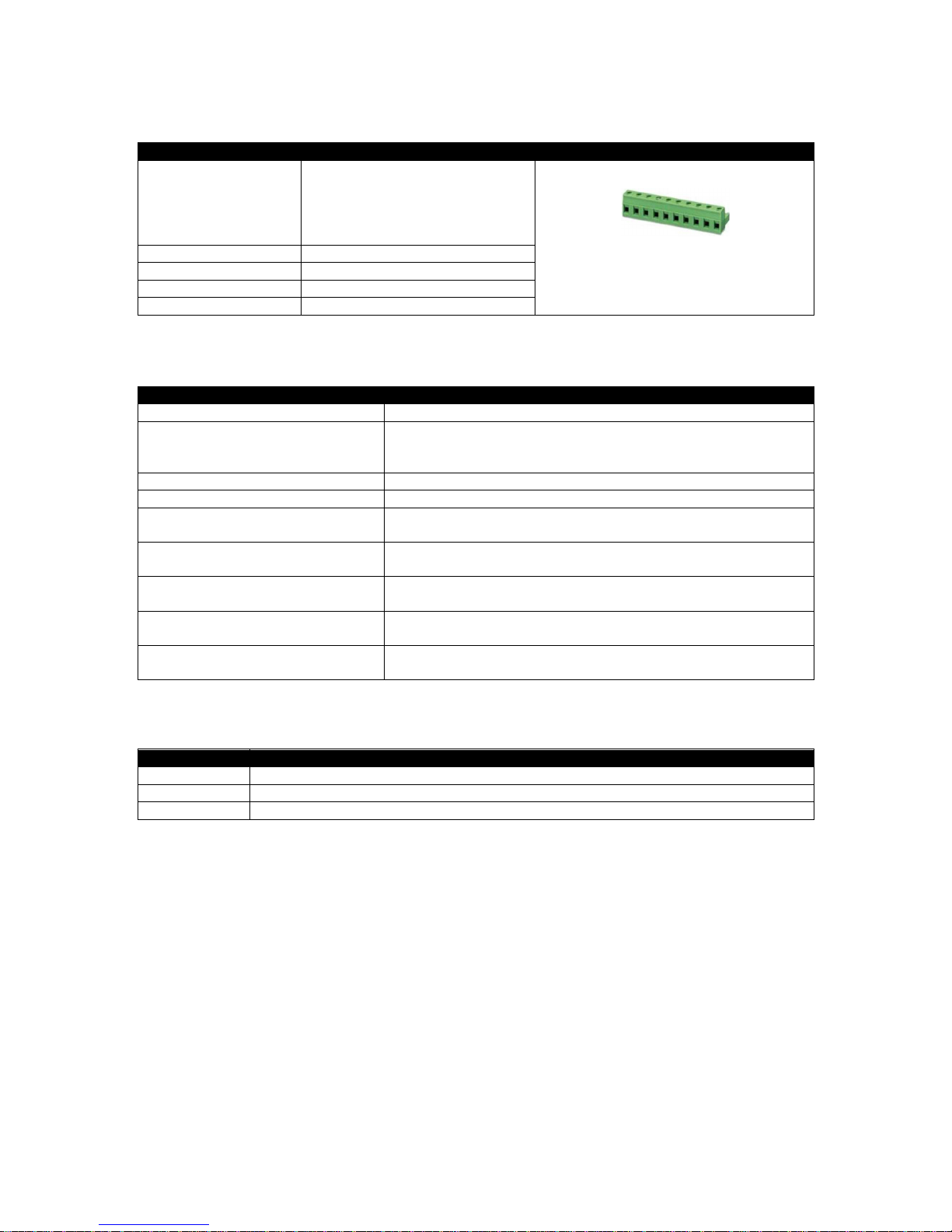
2.3 TERMINAL SPECIFICATION
Description
Specification
Connection Type
Two part connector.
Male part fitted to module
Female part supplied in module
packing case - Screw terminal,
rising clamp, no internal spring.
Example showing cable entry and screw
terminals of a 10 way connector
Minimum Cable Size 0.5 mm² (AWG 24)
Maximum Cable Size 2.5 mm² (AWG 12)
Tightening Torque 0.5 Nm (4.5 lb-in)
Wire Strip Length 7 mm (9/32”)
2.4 POWER SUPPLY REQUIREMENTS
Description
Specification
Minimum Supply Voltage 5 V continuous
Cranking Dropouts
Able to survive 0 V for 100 ms providing the supply was at least
was greater than 5 V for 2 seconds before the dropout and
recovers to 5 V afterwards.
Maximum Supply Voltage 35 V continuous (60 V protection)
Reverse Polarity Protection -35 V continuous
Maximum Operating Current
530 mA at 12 V
280 mA at 24 V
Maximum Standby Current
320 mA at 12 V
120 mA at 24 V
Maximum Current When In Sleep
Mode
140 mA at 12 V
75 mA at 24 V
Typical Power
(Controller On, Heater Off)
3.8 W to 4.1 W
Typical Power
(Controller On, Heater On)
6.8 W to 7.1 W
2.4.1 MODULE SUPPLY INSTRUMENTATION DISPLAY
Description
Specification
Range 0 V to 70 V DC (Maximum continuous operating voltage of 35 V DC)
Resolution 0.1 V
Accuracy 1 % full scale (±0.35 V)
Page 15

Specification
Page 15 of 188 057-254 ISSUE: 2
2.5 VOLTAGE & FREQUENCY SENSING
Description
Specification
Measurement Type True RMS conversion
Sample Rate 40 kHz
Harmonics Up to 21st or better
Input Impedance
300 kΩ phase to neutral
Phase To Neutral
15 V (minimum required for sensing frequency) to 415 V AC
(absolute maximum)
Suitable for 345 V AC nominal
(±20 % for under/overvoltage detection)
Phase To Phase
25 V (minimum required for sensing frequency) to 720 V AC
(absolute maximum)
Suitable for 600 V AC nominal
(±20 % for under/overvoltage detection)
Common Mode Offset From Earth 100 V AC (max)
Resolution
1 V AC phase to neutral
2 V AC phase to phase
Accuracy
±1 % of full scale phase to neutral
±2 % of full scale phase to phase
Minimum Frequency 3.5 Hz
Maximum Frequency 75.0 Hz
Frequency Resolution 0.1 Hz
Frequency Accuracy ±0.05 Hz
2.6 CURRENT SENSING
Description
Specification
Measurement Type True RMS conversion
Sample Rate 40 kHz
Harmonics Up to 21st or better
Nominal CT Secondary Rating 1 A and 5 A
Maximum Continuous Current 5 A
Overload Measurement 15 A
Absolute Maximum Overload 50 A for 1 second
Burden
0.5 VA (0.02 Ω current shunts)
Common Mode Offset
70 V peak plant ground to CT common terminal under fault
condition
Resolution 25 mA
Accuracy ±1 % of Nominal (excluding CT error)
Page 16
Specification
057-254 ISSUE: 2 Page 16 of 188
2.6.1 VA RATING OF THE CTS
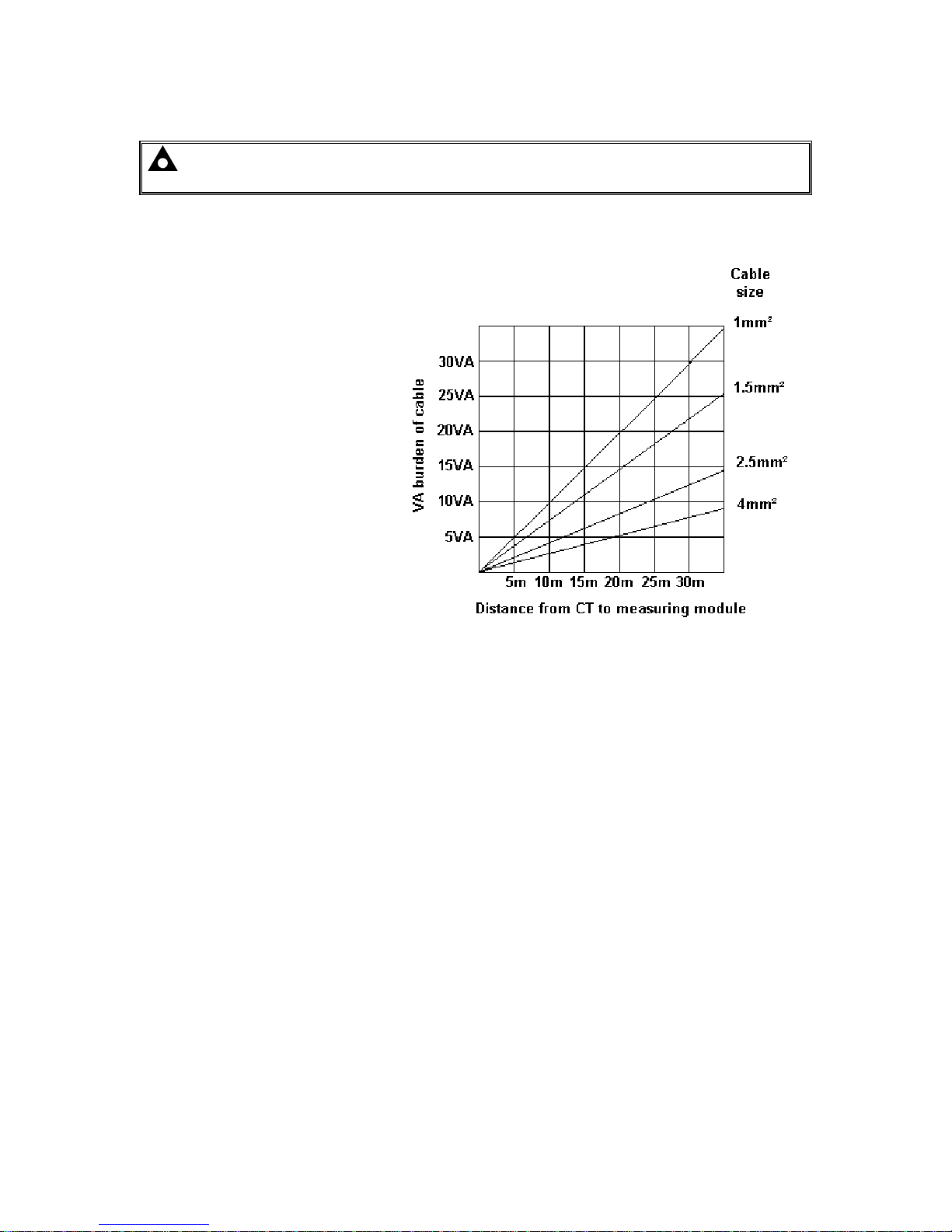
NOTE: Details for 4 mm² cables are shown for reference only. The connectors on the DSE
modules are only suitable for cables up to 2.5 mm².
The VA burden of the module on the CTs is 0.5 VA. However depending upon the type and length of
cabling between the CTs and the module, CTs with a greater VA rating than the module are required.
The distance betwe
en the CTs and the
measuring module should be
estimated and cross-referenced
against the chart opposite to find the
VA burden of the cable itself.
If the CTs are fitted within the
alternator top box, the star point
(common) of the CTs should be
connected to system ground (earth) as
close as possible to the CTs. This
minimises the length of cable used to
connect the CTs to the DSE module.
Example:
If 1.5 mm² cable is used and the
distance from the CT to the measuring
module is 20 m, then the burden of the
cable alone is approximately 15 VA.
As the burden of the DSE controller is
.5 VA, then a CT with a rating of at
least 15 VA + 0.5 VA = 15.5 VA must
be used. 0.5 VA, then a CT with a rating of at least 15 VA + 0.5 VA = 15.5 VA must be used. If 2.5
mm² cables are used over the same distance of 20 m, then the burden of the cable on the CT is
approximately 7 VA. CT’s required in this instance is at least 7.5 VA (7 + 0.5).
Page 17
Specification
Page 17 of 188 057-254 ISSUE: 2
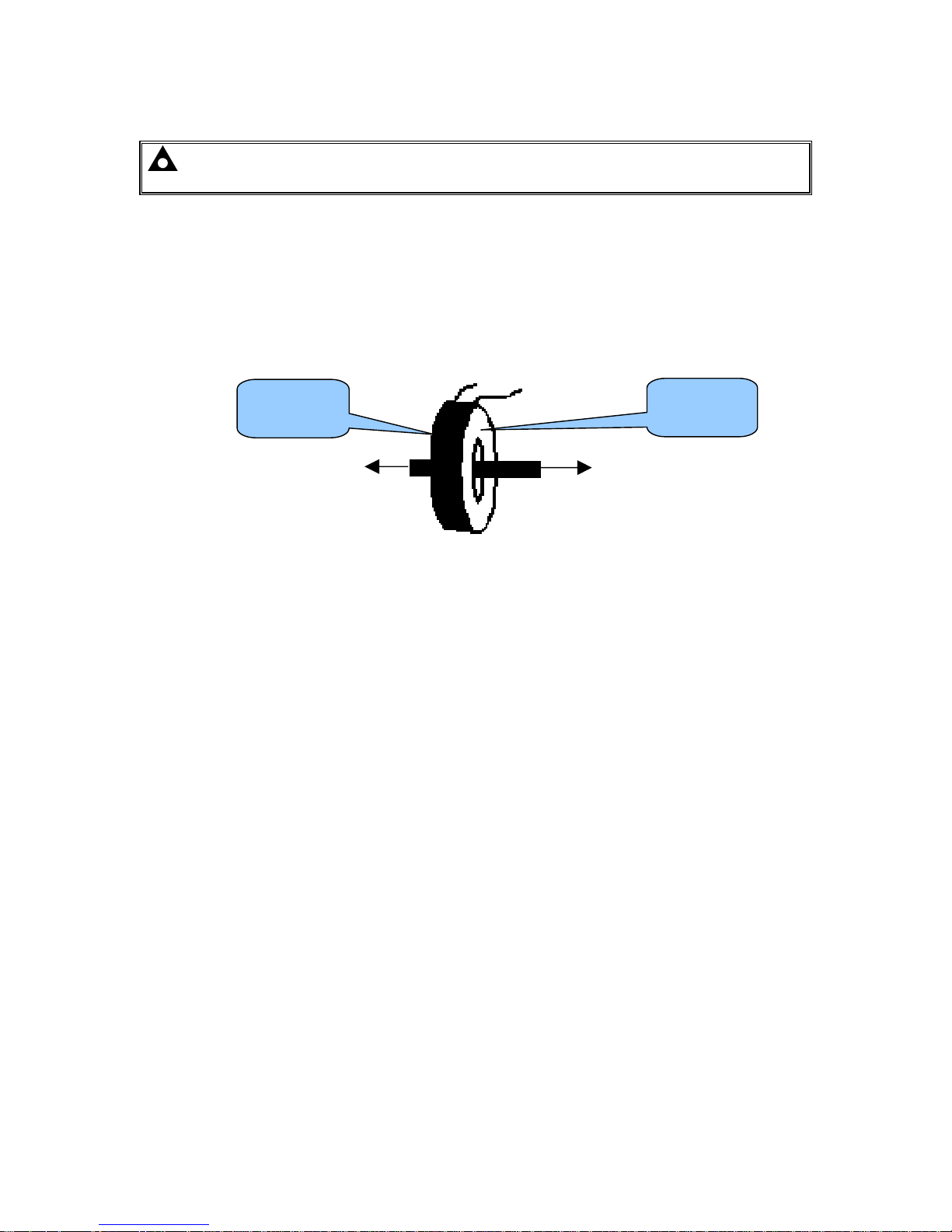
2.6.2 CT POLARITY
NOTE: Take care to ensure correct polarity of the CT primary as shown above. If in doubt,
check with the CT supplier.
Take care to ensure the correct polarity of the CTs. Incorrect CT orientation leads to negative kW
readings when the set is supplying power. Take note that paper stick-on labels on CTs that show the
orientation are often incorrectly placed on the CT. It is more reliable to use the labelling in the case
moulding as an indicator to orientation (if available).
To test orientation, run the generator in island mode (not in parallel with any other supply) and load
the generator to around 10 % of the set rating. Ensure the DSE module shows positive kW for all
three individual phase readings.
To Generator
To Load
Polarity of CT Primary
2.6.3 CT PHASING
Take particular care that the CTs are connected to the correct phases. For instance, ensure that the
CT on phase 1 is connected to the terminal on the DSE module intended for connection to the CT for
phase 1.
Additionally ensure that the voltage sensing for phase 1 is actually connected to generator phase 1.
Incorrect connection of the phases as described above results in incorrect power factor (pf)
measurements, which in turn results in incorrect kW measurements.
One way to check for this is to make use of a single-phase load. Place the load on each phase in turn,
run the generator and ensure the kW value appears in the correct phase. For instance if the load is
connected to phase 3, ensure the kW figure appears in phase 3 display and not in the display for
phase 1 or 2.
2.6.4 CT CLASS
Ensure the correct CT type is chosen. For instance if the DSE module is providing over current
protection, ensure the CT is capable of measuring the overload level required to protect against, and
at the accuracy level required.
For instance, this may mean fitting a protection class CT (P15 type) to maintain high accuracy while
the CT is measuring overload currents.
Conversely, if the DSE module is using the CT for instrumentation only (current protection is disabled
or not fitted to the controller), then measurement class CTs can be used. Again, bear in mind the
accuracy required. The DSE module is accurate to better than 1% of the full-scale current reading. To
maintain this accuracy, fit a Class 0.5 or Class 1 CT.
Check with the CT manufacturer for further advice on selecting CTs.
Labelled as
p1, k or K
Labelled as
p2, l or L
Page 18

Specification
057-254 ISSUE: 2 Page 18 of 188
2.7 INPUTS
2.7.1 DIGITAL INPUTS
Description
Specification
Number
12 configurable digital inputs
(16 when Analogue Inputs are configured as digital inputs)
Arrangement Contact between terminal and ground
Low Level Threshold 2.1 V minimum
High Level Threshold 6.6 V maximum
Maximum Input Voltage +50 V DC with respect to plant supply negative
Minimum Input Voltage -24 V DC with respect to plant supply negative
Contact Wetting Current 7 mA typical
Open Circuit Voltage 12 V typical
2.7.2 EMERGENCY STOP
Description
Specification
Arrangement Contact between terminal and module supply positive
Closed Threshold 5 V minimum
Open Threshold 3 V maximum
Maximum Input Voltage
+35 V DC with respect to plant supply negative
(60 V protection for 1 minute)
Minimum Input Voltage -24 V DC with respect to plant supply negative
Open Circuit Voltage 0 V
Page 19

Specification
Page 19 of 188 057-254 ISSUE: 2
2.7.3 ANALOGUE INPUTS
All of the analogue inputs are flexible within the DSE8610 MKII module
2.7.3.1 ANALOGUE INPUT A
Description
Specification
Input Type
Flexible: Configured for Oil Sensor in the DSE default configuration.
Flexible Options: Not used, Digital Input, Flexible Analogue Oil
Sensor
Flexible Input Selection Pressure Sensor, Percentage Sensor or Temperature Sensor
Flexible Measured Quantity Current, Restive or Voltage
Resistive Configuration
Description
Specification
Measurement Type
Resistance measurement by measuring voltage across sensor with
a fixed current applied
Arrangement Differential resistance measurement input
Measurement Current 15 mA ± 2 mA %
Full Scale
480 Ω
Over Range / Fail
600 Ω
Resolution ±1 % of full scale
Accuracy
±2 % of full scale resistance (±9.6 Ω) excluding sensor error
Max Common Mode Voltage ±2 V
Display Range
0 % to 250 %, 0 °C to 250 °C (32 °F to 482 °F) or 0 bar to 17.2 bar
(0 PSI to 250 PSI) subject to limits of the sensor and sensor
configuration
0 V to 10 V Configuration
Description
Specification
Full Scale 0 V to 10 V
Over Range / Fail 11 V
Resolution ±1% of full scale
Accuracy ±2% of full scale voltage (±0.2 V) excluding sensor error
Max Common Mode Voltage ±2 V
Display Range
0 % to 250 %, 0 °C to 250 °C (32 °F to 482 °F) or 0 bar to 17.2 bar
(0 PSI to 250 PSI) subject to limits of the sensor and sensor
configuration
4 mA to 20 mA Configuration
Description
Specification
Full Scale 0 mA to 20 mA
Over Range / Fail 22 mA
Resolution 1% of full scale
Accuracy ±2% of full scale current (±0.4 mA) excluding sensor error
Max Common Mode Voltage ±2 V
Display Range
0 % to 250 %, 0 °C to 250 °C (32 °F to 482 °F) or 0 bar to 17.2 bar
(0 PSI to 250 PSI) subject to limits of the sensor and sensor
configuration
Page 20

Specification
057-254 ISSUE: 2 Page 20 of 188
2.7.3.2 ANALOGUE INPUT B, C & D
Description
Specification
Analogue Input B Type
Flexible: Configured for Temperature Sensor in the DSE default
configuration.
Flexible Options: Not used, Digital Input and Flexible Analogue
Analogue Input C Type
Flexible: Configured for Fuel Sensor in the DSE default
configuration.
Flexible Options: Not used, Digital Input and Flexible Analogue
Analogue Input D Type
Flexible: Configured for Flexible Analogue in the DSE default
configuration.
Flexible Options: Not used, Digital Input and Flexible Analogue
Flexible Input Selection Pressure Sensor, Percentage Sensor or Temperature Sensor
Flexible Measured Quantity Current, Restive or Voltage
Resistive Configuration
Description
Specification
Measurement Type
Resistance measurement by measuring voltage across sensor with
a fixed current applied
Arrangement Differential resistance measurement input
Measurement Current 15 mA ±10 %
Full Scale
480 Ω
Over Range / Fail
600 Ω
Resolution ±1 % of full scale
Accuracy
±2 % of full scale resistance (±9.6 Ω) excluding sensor error
Max Common Mode Voltage ±2 V
Display Range
0 % to 250 %, 0 °C to 250 °C (32 °F to 482 °F) or 0 bar to 17.2 bar
(0 PSI to 250 PSI) subject to limits of the sensor and sensor
configuration
0 V to 10 V Configuration
Description
Specification
Full Scale 0 V to 10 V
Over Range / Fail 11 V
Resolution ±1% of full scale
Accuracy ±2% of full scale voltage (±0.2 V) excluding sensor error
Max Common Mode Voltage ±2 V
Display Range
0 % to 250 %, 0 °C to 250 °C (32 °F to 482 °F) or 0 bar to 17.2 bar
(0 PSI to 250 PSI) subject to limits of the sensor and sensor
configuration
4 mA to 20 mA Configuration
Description
Specification
Full Scale 0 mA to 20 mA
Over Range / Fail 22 mA
Resolution ±1% of full scale
Accuracy ±2% of full scale current (±0.4 mA) excluding sensor error
Max Common Mode Voltage ±2 V
Display Range
0 % to 250 %, 0 °C to 250 °C (32 °F to 482 °F) or 0 bar to 17.2 bar
(0 PSI to 250 PSI) subject to limits of the sensor and sensor
configuration
Page 21
Specification
Page 21 of 188 057-254 ISSUE: 2
2.7.4 CHARGE FAIL INPUT
The charge fail input is actually a combined input and output. Whenever the generator is required to
run, the terminal provides excitation current to the charge alternator field winding.
When the charge alternator is correctly charging the battery, the voltage of the terminal is close to the
plant battery supply voltage. In a failed charge situation, the voltage of this terminal is pulled down to
a low voltage. It is this drop in voltage that triggers the Charge Failure alarm. The level at which this
operates and whether this triggers a warning or shutdown alarm is configurable using the DSE
Configuration Suite Software.
Description
Specification
Minimum Voltage 0 V
Maximum Voltage 35 V
Resolution 0.2 V
Accuracy ±1 % of full scale
Excitation Active circuit constant power output
Output Power 2.5 W nominal at 12 V and 24 V
Current At 12V 210 mA
Current At 24V 105 mA
2.7.5 MAGNETIC PICK-UP
NOTE: DSE supply a suitable magnetic pickup device, available in two body thread
lengths:
DSE Part number 020-012 - Magnetic Pickup probe 5/8 UNF 2 ½” thread length
DSE Part number 020-013 - Magnetic Pickup probe 5/8 UNF 4” thread length
Magnetic Pickup devices can often be ‘shared’ between two or more devices. For example, one
device can often supply the signal to both the DSE module and the engine governor. The possibility of
this depends upon the amount of current that the magnetic pickup can supply.
Description
Specification
Type Differential input
Minimum Voltage 0.5 V RMS
Maximum Voltage 70 V RMS
Max Common Mode Voltage ±2 V peak
Minimum Frequency 5 Hz
Maximum Frequency 10,000 Hz
Resolution 6.25 rpm
Accuracy ± 25 rpm
Flywheel Teeth 10 to 500
Page 22
Specification
057-254 ISSUE: 2 Page 22 of 188
2.8 OUTPUTS
2.8.1 DC OUTPUTS A & B (FUEL & START)
Description
Specification
Type
Normally used as Fuel & Start outputs.
Fully configurable for other purposes if the module is configured to control an
electronic engine.
Rating 15 A resistive at Emergency Stop supply.
2.8.2 CONFIGURABLE VOLT-FREE RELAY OUTPUTS C & D
Description
Specification
Type
Normally used for load switching control
Fully configurable volt-free relays.
Output C normally closed and Output D normal open.
Rating 8 A resistive at 250 V AC
2.8.3 CONFIGURABLE DC OUTPUTS E, F, G, H, I, J, K & L
Description
Specification
Type Fully configurable, supplied from DC supply terminal 2.
Rating 2 A resistive at module supply.
2.8.4 GOVERNOR CONTROL OUTPUT
Description
Specification
Arrangement Supplied from DC supply terminal 2
Type Isolated DC output, voltage controlled
Voltage Range -5 V to +10 V DC
Max Common Mode Voltage ±1 kV
Resolution Less than 1 mV
Accuracy ±1%
Minimum Load 500 Ω
2.8.5 AVR CONTROL OUTPUT
Description
Specification
Arrangement Supplied from DC supply terminal 2
Type Isolated DC output, voltage controlled
Voltage Range -5 V to +10 V DC
Max Common Mode Voltage ±3 kV
Resolution Less than 1 mV
Accuracy ±1 %
Minimum Load 500 Ω
Page 23
Specification
Page 23 of 188 057-254 ISSUE: 2
2.9 COMMUNICATION PORTS
NOTE: All communication ports can be used at the same time.
Description
Specification
USB Slave Port
Type B USB 2.0
For connection to PC running DSE Configuration Suite
Max distance 6 m (20 feet)
USB Host Port
Type A USB 2.0
Capability to add a maximum of 16 GB USB storage device for data
recording only
RS232 Serial Port
Non – isolated
Max Baud rate 115 k baud subject to configuration
TX, RX, RTS, CTS, DSR, DTR, DCD
Male 9 way D type connector
Max distance 15 m (50 feet)
2 x RS485 Serial Ports
Isolated
Data connection 2 wire + common
Half Duplex
Data direction control for Transmit (by s/w protocol)
Max Baud Rate 115 k baud subject to configuration
External termination required (120 Ω)
Max common mode offset 70 V (on board protection transorb)
Max distance 1.2 km (¾ mile)
Ethernet Auto detecting 10/100 Mbit Ethernet port.
MSC (Multi Set
Communication) and
CAN Port
NOTE: For additional length, the DSE124 CAN & MSC Extender
is available. For more information, refer to DSE Publication: 057-116
DSE124 Operator Manual
Standard implementation of ‘Slow mode’, up to 250K bits/s
Data connection 2 wire + common
Isolated
External termination required (120 Ω)
Max common mode offset 70 V (on board protection transorb)
Max distance 250 M using Belden 9841 Cable or equivalent
ECU Port
NOTE: For additional length, the DSE124 CAN & MSC Extender
is available. For more information, refer to DSE Publication: 057-116
DSE124 Operator Manual
Engine CAN Port
Standard implementation of ‘Slow mode’, up to 250 Kb/s
Non-Isolated.
Internal Termination enabled by software configuration provided (120 Ω)
Max distance 40 m (133 feet)
DSENet®
(Expansion Comms) Port
Non-isolated
Data connection 2 wire + common
Half Duplex
Data direction control for Transmit (by s/w protocol)
Baud Rate of 115 k baud
Internal termination fitted (120 Ω)
Max common mode offset ±5 V
Max distance 1.2 km (¾ mile)
Page 24
Specification
057-254 ISSUE: 2 Page 24 of 188
2.10 COMMUNICATION PORT USAGE
2.10.1 USB SLAVE PORT (PC CONFIGURATION)
NOTE: DSE stock 2 m (6.5 feet) USB type A to type B cable, DSE Part Number: 016-125.
Alternatively they are purchased from any PC or IT store.
NOTE: The DC supply must be connected to the module for configuration by PC.
NOTE: For further details of module configuration, refer to DSE Publication: 057-238
DSE8610 MKII Configuration Suite PC Software Manual.
The USB port is provided to give a simple means of connection between a PC and the controller.
Using the DSE Configuration Suite Software, the operator is then able to control the module, starting
or stopping the engine, selecting operating modes, etc.
Additionally, the various operating parameters (such as coolant temperature, oil pressure, etc.) of the
engine are available to be viewed or changed.
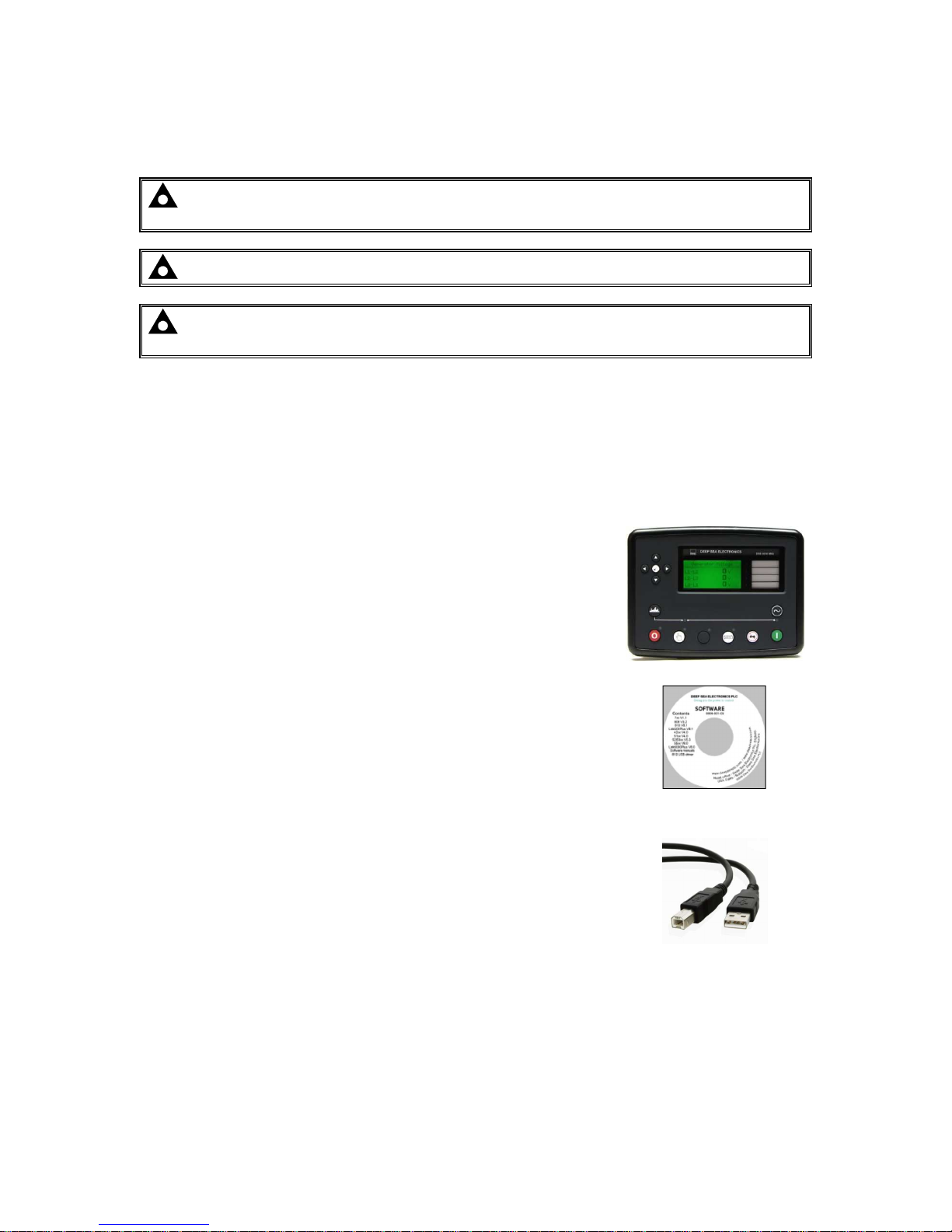
To connect a module to a PC by USB, the following items are required:
DSE86xx MKII Controller
DSE Configuration Suite PC Software
(Supplied on configuration suite software CD or available from
www.deepseaplc.com).
USB cable Type A to Type B.
(This is the same cable as often used between a PC and a USB
printer)
DSE can supply this cable if required :
PC Configuration interface lead (USB type A – type B) DSE Part No
016-125
2.10.1.1 USB HOST PORT (DATA LOGGING)
USB Type A connection for an of external USB storage device of maximum 16 GB for instrumentation
data logging.
Page 25
Specification
Page 25 of 188 057-254 ISSUE: 2
2.10.2 RS232 PORT
NOTE: For direct connection an RS232 null modem (crossover) cable is required. This is
rated to a maximum cable length of 15 m.
NOTE: For a single module to PC connection and distances up to 6 m (20 feet) the USB
connection method is more suitable and provides for a lower cost alternative to RS485 (which
is more suited to longer distance connections).
The RS232 port on the controller supports the MODBUS RTU protocol and is for connection to a
single MODBUS master device only.
The MODBUS register table for the controller is available upon request from the DSE Technical
Support Department.
RS232 is for short distance communication (max 15m) and is typically used to connect the controller
to a telephone or GSM modem for more remote communications.
The various operating parameters (such as coolant temperature, oil pressure, etc.) of the remote
engine are viewed or changed.
Many PCs are not fitted with an internal RS232 serial port. DSE DOES NOT recommend the use of
USB to RS232 convertors but can recommend PC add-ons to provide the computer with an RS232
port.
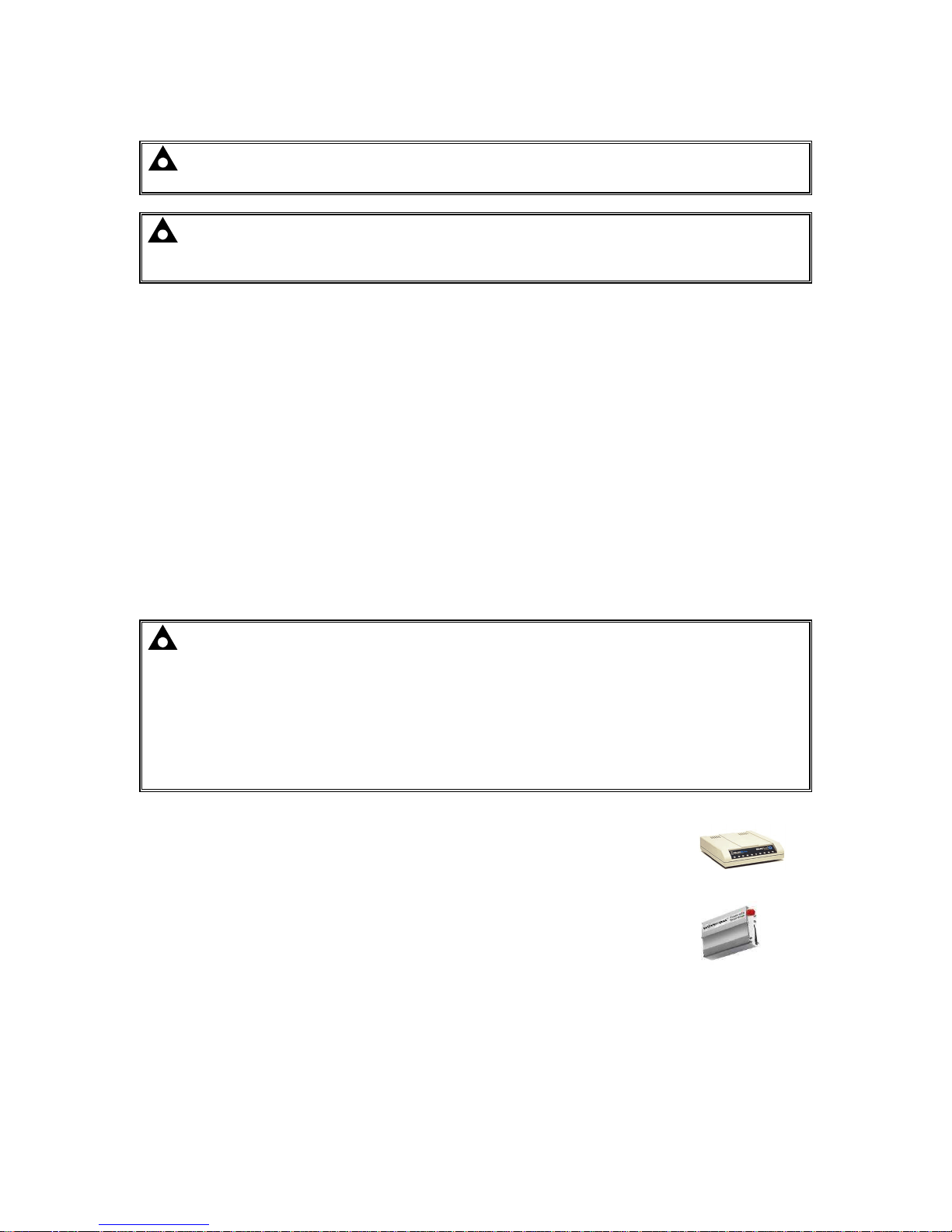
2.10.2.1 RECOMMENDED EXTERNAL MODEMS
NOTE: For GSM modems a SIM card is required, supplied by the GSM network provider:
For SMS only, a ‘normal’ voice SIM card is required. This enables the controller to send SMS
messages to designated mobile phones upon status and alarm conditions.
For a data connection to a PC running DSE Configuration Suite Software, a ‘special’ CSD
(Circuit Switched Data) SIM card is required that enables the modem to answer an incoming
data call. Many ‘pay as you go’ services do not provide a CSD (Circuit Switched Data) SIM
card.
Multitech Global Modem – MultiModem ZBA (PSTN)
DSE Part Number 020-252
(Contact DSE Sales for details of localisation kits for these modems)
Sierra Fastrak Xtend GSM modem kit (PSU, Antenna and modem)*
DSE Part number 0830-001-01
Page 26
Specification
057-254 ISSUE: 2 Page 26 of 188
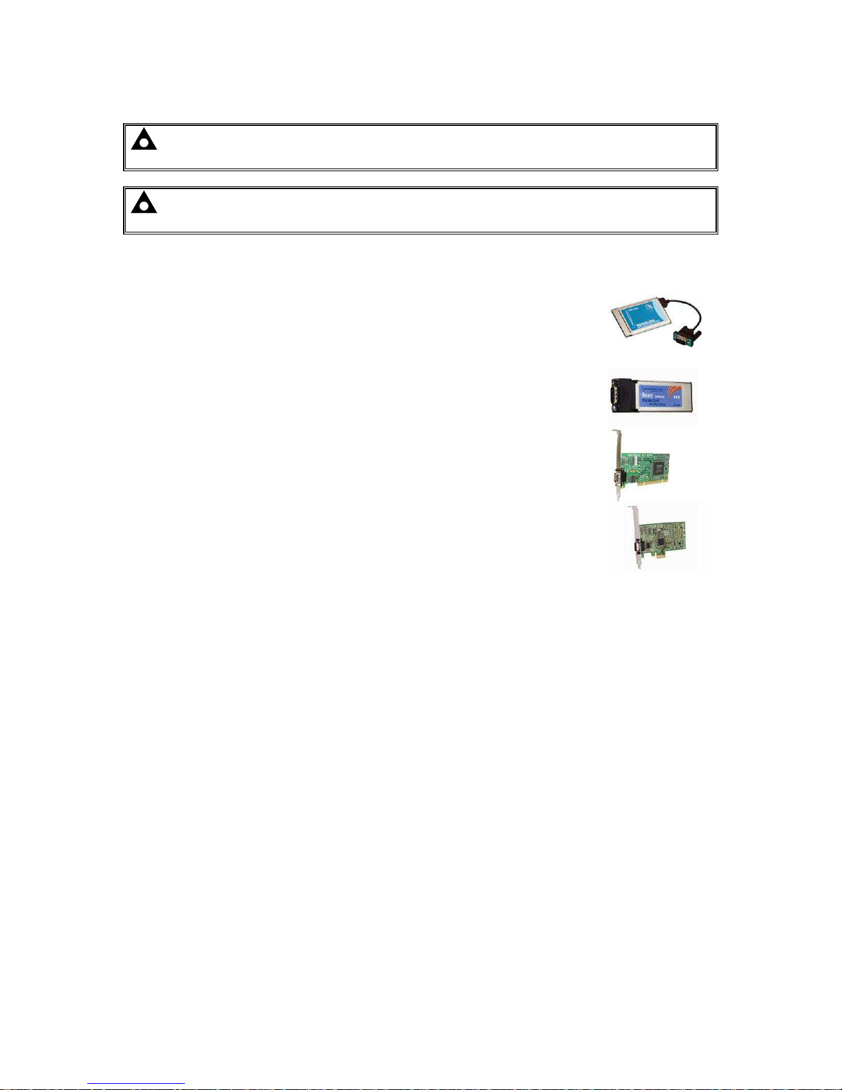
2.10.2.2 RECOMMENDED PC RS232 SERIAL PORT ADD-ONS
NOTE: DSE have no business tie to Brainboxes. Over many years, our own engineers
have used these products and are happy to recommend them.
NOTE: For further details of setting up the devices below, refer to the manufacture whose
details are below.
Remember to check these parts are suitable for your PC. Consult your PC supplier for further advice.
Brainboxes PM143 PCMCIA RS232 card (for laptop PCs)
Brainboxes VX-001 Express Card RS232 (for laptops and nettops PCs)
Brainboxes UC246 PCI RS232 card (for desktop PCs)
Brainboxes PX-246 PCI Express 1 Port RS232 1 x 9 Pin (for desktop PCs)
Supplier:
Brainboxes
Tel: +44 (0)151 220 2500
Web: http://www.brainboxes.com
Email: Sales: sales@brainboxes.com
Page 27
Specification
Page 27 of 188 057-254 ISSUE: 2
2.10.3 RS485 PORT
NOTE: For a single module to PC connection and distances up to 6 m (20 feet) the USB
connection method is more suitable and provides for a lower cost alternative to RS485 (which
is more suited to longer distance connections).
The RS485 port on the controller supports the MODBUS RTU protocol and is for connection to a
single MODBUS master device only.
The DSE MODBUS register table for the controller is available upon request from the DSE Technical
Support Department.
RS485 is used for point-to-point cable connection of more than one device (maximum 32 devices)
and allows for connection to PCs, PLCs and Building Management Systems (to name just a few
devices).
One advantage of the RS485 interface is the large distance specification (1.2 km when using Belden
9841 (or equivalent) cable. This allows for a large distance between the module and a PC running the
DSE Configuration Suite software. The operator is then able to control the module, starting or
stopping the engine, selecting operating modes, etc.
The various operating parameters (such as coolant temperature, oil pressure, etc.) of the remote
engine are viewed or changed.
Many PCs are not fitted with an internal RS485 serial port. DSE DOES NOT recommend the use of
USB to RS485 convertors but can recommend PC add-ons to provide the computer with an
RS485port.
2.10.3.1 CABLE SPECIFICATION
NOTE: DSE recommend Belden 9841 (or equivalent) cable for RS485 communication. This
is rated to a maximum cable length of 1.2 km. DSE Stock Belden 9841 cable, DSE Part Number:
016-030.
Description
Specification
Cable Type Two core screened and shielded twisted pair
Cable Characteristics
120 Ω impedance
Low capacitance
Recommended Cable
Belden 9841
Belden 9271
Maximum Cable Length
1200 m (¾ mile) when using Belden 9841 or direct equivalent.
600 m (656 yards) when using Belden 9271 or direct equivalent.
RS485 Topology “Daisy Chain” Bus with no stubs (spurs)
RS485 Termination
120 Ω. Not fitted internally to module. Must be fitted externally to the ‘first’
and ‘last’ device on the RS485 link.
Page 28

Specification
057-254 ISSUE: 2 Page 28 of 188
2.10.3.2 RECOMMENDED PC RS485 SERIAL PORT ADD-ONS
NOTE: DSE have no business tie to Brainboxes. Over many years, our own engineers
have used these products and are happy to recommend them.
NOTE: For further details of setting up the devices below, refer to the manufacture whose
details are below.
Remember to check these parts are suitable for your PC. Consult your PC supplier for further advice.
Brainboxes PM154 PCMCIA RS485 card (for laptops PCs)
Set to ‘Half Duplex, Autogating” with ‘CTS True’ set to ‘enabled’
Brainboxes VX-023 ExpressCard 1 Port RS422/485 (for laptops and nettop PCs)
Brainboxes UC320 PCI Velocity RS485 card (for desktop PCs)
Set to ‘Half Duplex, Autogating” with ‘CTS True’ set to ‘enabled’
Brainboxes PX-324 PCI Express 1 Port RS422/485 (for desktop PCs)
Supplier:
Brainboxes
Tel: +44 (0)151 220 2500
Web: http://www.brainboxes.com
Email: Sales: sales@brainboxes.com
Page 29

Specification
Page 29 of 188 057-254 ISSUE: 2
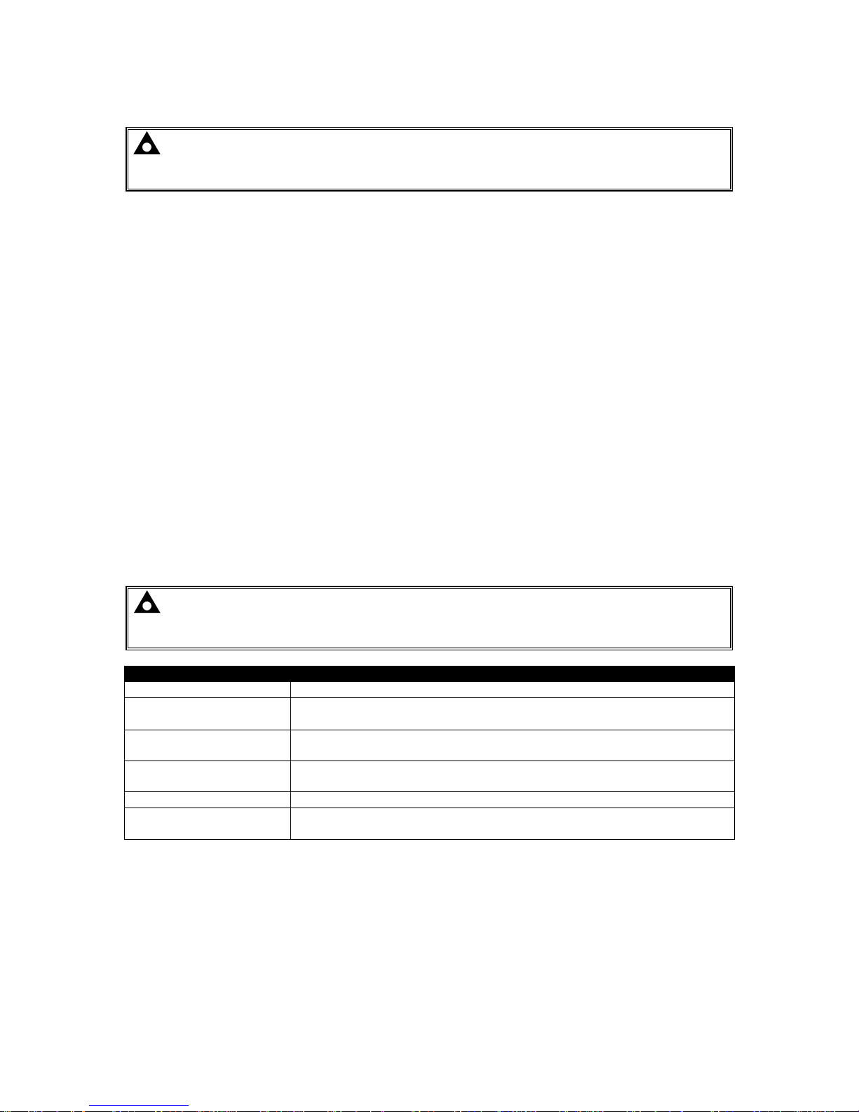
2.10.3.3 RS485 USED FOR MODBUS ENGINE CONNECTION
NOTE: For further details of module configuration, refer to DSE Publication: 057-238
DSE8610 MKII Configuration Suite PC Software Manual.
The RS485 port can be configured for connection to Cummins MODBUS engines (Engines fitted with
Cummins GCS (G-Drive Control System)).
This leaves the DSENet® interface free for connection to expansion devices.
While this is a very useful feature in some applications, the obvious drawback is that the RS485
interface is no longer available connection or remote monitoring equipment (i.e. Building Management
System, PLC or PC RS232 port) or dual mutual system.
Example of configuring the
DSENet® for connection to
Cummins QSK GCS using the
DSE Configuration Suite
Software:
Page 30
Specification
057-254 ISSUE: 2 Page 30 of 188
2.10.4 ETHERNET PORT
The Ethernet port on the controller supports the Modbus TCP protocol and is for connection for up to
five Modbus master devices.
NOTE: For further details of module configuration, refer to DSE Publication: 057-238
DSE8610 MKII Configuration Suite PC Software Manual.
The DSE MODBUS register table for the controller is available upon request from the DSE Technical
Support Department.
Ethernet is used for point-to-point cable connection of more than one device and allows for
connection to PCs, PLCs and Building Management Systems (to name just a few devices).
One advantage of the Ethernet interface is the ability to interface into an existing LAN (Local Area
Network) connection for remote connection via an internet connection. This allows for a large distance
between the module and a PC running the DSE Configuration Suite software. The operator is then
able to control the module, starting or stopping the engine, selecting operating modes, etc.
The various operating parameters (such as coolant temperature, oil pressure, etc.) of the remote
engine are viewed or changed.
NOTE: For a single module to PC connection and distances up to 6 m (20 feet) the USB
connection method is more suitable and provides for a lower cost alternative to Ethernet
(which is more suited to longer distance connections).
NOTE: DSE stock 2 m (6.5 feet) Ethernet Cable, DSE Part Number: 016-137. Alternatively
they can be purchased from any PC or IT store.
Page 31

Specification
Page 31 of 188 057-254 ISSUE: 2
2.10.4.1 DIRECT PC CONNECTION
Requirements
• Ethernet cable (see below)
• PC with Ethernet port
Ethernet Cable Wiring Detail
NOTE: DSE stock 2 m (6.5 feet) Ethernet Cable, DSE Part Number: 016-137. Alternatively
they can be purchased from any PC or IT store.
Pin Connection 1 (T568A)
Connection 2 (T568A)
1
white/green
stripe
white/green
stripe
2
green solid
green solid
3
white/orange
stripe
white/orange
stripe
4
blue solid
blue solid
5
white/blue
stripe
white/blue
stripe
6
orange solid
orange solid
7
white/brown
stripe
white/brown
stripe
8
brown solid
brown solid
Network Cable
Page 32

Specification
057-254 ISSUE: 2 Page 32 of 188
2.10.4.2 CONNECTION TO BASIC ETHERNET
Requirements
• Ethernet cable (see below)
• Working Ethernet (company or home network)
• PC with Ethernet port
Ethernet Cable Wiring Detail
NOTE: DSE stock 2 m (6.5 feet) Ethernet Cable, DSE Part Number: 016-137. Alternatively
they can be purchased from any PC or IT store.
Pin Connection 1 (T568A)
Connection 2 (T568A)
1
white/green
stripe
white/green
stripe
2
green solid
green solid
3
white/orange
stripe
white/orange
stripe
4
blue solid
blue solid
5
white/blue
stripe
white/blue
stripe
6
orange solid
orange solid
7
white/brown
stripe
white/brown
stripe
8
brown solid
brown solid
Ethernet Router
or ADSL Router
Ethernet Cable
Page 33

Specification
Page 33 of 188 057-254 ISSUE: 2
2.10.4.3 CONNECTION TO COMPANY ETHERNET INFRASTRUCTURE
Requirements
• DSE module with the ability to connect to Ethernet
• Ethernet cable (see below)
• Working Ethernet (company or home network)
• PC with Ethernet port
Ethernet Cable Wiring Detail
NOTE: DSE stock 2 m (6.5 feet) Ethernet Cable, DSE Part Number: 016-137. Alternatively
they can be purchased from any PC or IT store.
Pin Connection 1 (T568A)
Connection 2 (T568A)
1
white/green
stripe
white/green
stripe
2
green solid
green solid
3
white/orange
stripe
white/orange
stripe
4
blue solid
blue solid
5
white/blue
stripe
white/blue
stripe
6
orange solid
orange solid
7
white/brown
stripe
white/brown
stripe
8
brown solid
brown solid
PC Network
Wall
Connection
Sockets
Ethernet Router
or ADSL Router
Ethernet
Cable
For the advanced
Engineer, this cable has
both ends terminated as
T568A or T568B.
Page 34

Specification
057-254 ISSUE: 2 Page 34 of 188
2.10.4.4 CONNECTION TO THE INTERNET
Requirements
• Ethernet cable (see below)
• Working Ethernet (company or home network)
• Working Internet connection (ADSL or DSL recommended)
Ethernet Cable Wiring Detail
NOTE: DSE stock 2 m (6.5 feet) Ethernet Cable, DSE Part Number: 016-137. Alternatively
they can be purchased from any PC or IT store.
Pin Connection 1
(T568A)
Connection 2 (T568A)
1
white/green
stripe
white/green
stripe
2
green solid
green solid
3
white/orange
stripe
white/orange
stripe
4
blue solid
blue solid
5
white/blue
stripe
white/blue
stripe
6
orange solid
orange solid
7
white/brown
stripe
white/brown
stripe
8
brown solid
brown solid
DSL or ADSL
Router
Optional ‘Local’
Site PC
INTERNET
PC Remote From
Generator Site
The DSL/ADSL
router routes
external network
traffic
Ethernet
Cable
DSL or ADSL
Router
Page 35

Specification
Page 35 of 188 057-254 ISSUE: 2
2.10.4.5 FIREWALL CONFIGURATION FOR INTERNET ACCESS
NOTE: For further details of module configuration, refer to DSE Publication: 057-238
DSE8610 MKII Configuration Suite PC Software Manual.
As modem/routers differ enormously in their configuration, it is not possible for DSE to give a
complete guide to their use with the module. However it is possible to give a description of the
requirements in generic terms. For details of how to achieve the connection to your modem/router you
are referred to the supplier of your modem/router equipment.
The module makes its data available over Modbus TCP and as such communicates over the Ethernet
using a Port configured via the DSE Configuration Suite software.
You must configure your modem/router to allow inbound traffic on this port. For more information you
are referred to your WAN interface device (modem/router) manufacturer.
It is also important to note that if the port assigned (setting from software “Modbus Port Number”) is
already in use on the LAN, the module cannot be used and another port must be used.
Outgoing Firewall Rule
As the module makes its user interface available to standard web browsers, all communication uses
the chosen port. It is usual for a firewall to make the same port outgoing open for communication.
Incoming Traffic (Virtual Server)
Network Address and Port Translation (NAPT) allows a single device, such as the modem/router
gateway, to act as an agent between the Internet (or "public external network") and a local (or
"internal private") network. This means that only a single, unique IP address is required to represent
an entire group of computers.
For our application, this means that the WAN IP address of the modem/router is the IP address we
need to access the site from an external (internet) location.
When the requests reach the modem/router, we want this passed to a ‘virtual server’ for handling, in
our case this is the module.
Result: Traffic arriving from the WAN (internet) on port xxx is automatically sent to IP address set
within the configuration software on the LAN for handling.
Page 36

Specification
057-254 ISSUE: 2 Page 36 of 188
2.10.5 MSC (MULTI-SET COMMUNICATIONS) LINK
NOTE: For further details of module configuration, refer to DSE Publication: 057-238
DSE8610 MKII Configuration Suite PC Software Manual.
NOTE: A termination resistor MUST be fitted to the first and last unit on the MSC link. For
connection details, refer to section entitled Typical Arrangement of MSC Link elsewhere in this
document.
NOTE: DSE recommend Belden 9841 (or equivalent) cable for MSC communication. This
is rated to a maximum cable length of 250 m. DSE Stock Belden 9841 cable, DSE Part Number:
016-030.
NOTE: By default the MSC link of the DSE8xxx modules are not compatible with the
DSE55xx/DSE75xx modules. For details on enabling compatibility, refer to section entitled
MSC Compatibility elsewhere in this document.
The MSC link is the interconnection cable between all DSE synchronising controllers and must not be
connected to any device other than DSE equipment designed for connection to the MSC link.
Description
Specification
Cable Type Two core screened and shielded twisted pair
Cable Characteristics
120 Ω
Low capacitance
Recommended Cable
Belden 9841
Belden 9271
Maximum Cable
Length
NOTE: For additional length, the DSE124 CAN & MSC Extender is
available. For more information, refer to DSE Publication: 057-116
DSE124 Operator Manual
250 m (¾ mile) when using Belden 9841 or direct equivalent.
125 m (656 yards) when using Belden 9271 or direct equivalent.
MSC Topology “Daisy Chain” Bus with no stubs (spurs)
MSC Termination
120 Ω.
Must be fitted externally to the first and last module.
Maximum DSE8xxx
and DSE8xxx MKII
Modules
NOTE: If any number of DSE8x60 are on the MSC link, a maximum
of 2x DSE8x80 can be used. For each DSE8x80 used, the number of
available DSE8x60s to be used reduces.
Total 40 devices made up of DSE8x10 (up to 32), DSE8x60 (up to 16) and
DSE8x80 (up to 16)
This gives the possibility of :
• 32 generators (DSE8x10) and 8 synchronising transfers (DSE8x60)
• 32 generators (DSE8x10) and 8 generator bus couplers (DSE8x80)
• 24 generators (DSE8x10) and 16 synchronising transfers (DSE8x60)
• 24 generators (DSE8x10) and 16 generator bus couplers (DSE8x80)
• 32 generators (DSE8x10), 14 synchronising transfers (DSE8x60)
and 2 generator bus couplers (DSE8x80)
Page 37

Specification
Page 37 of 188 057-254 ISSUE: 2
2.10.7 CAN PORT
NOTE: At the time of writing this document the CAN Port is not available. The CAN Port
functionality is to be made available in a future update. Contact DSE technical support for
further information, support@deepseaplc.com.
2.10.8 ECU PORT (J1939)
NOTE: For further details of module configuration, refer to DSE Publication: 057-238
DSE8610 MKII Configuration Suite PC Software Manual.
NOTE: For further details on connection to electronic engines, refer to DSE Publication:
057-004 Electronic Engines And DSE Wiring
NOTE: Screened 120 ΩΩΩΩ impedance cable specified for use with CAN must be used for the
CAN link.
DSE stock and supply Belden cable 9841 which is a high quality 120 ΩΩΩΩ impedance cable
suitable for CAN use (DSE part number 016-030)
NOTE: For additional length, the DSE124 CAN & MSC Extender is available. For more
information, refer to DSE Publication: 057-116 DSE124 Operator Manual
The modules are fitted with a CAN interface as standard and are capable
of receiving engine data from engine ECU/ECMs compliant with the CAN
J1939 standard.
ECU/ECMs monitor the engine’s operating parameters such as speed,
oil pressure, coolant temperature (among others) in order to closely monitor and control the engine.
The industry standard communications interface (CAN) transports data gathered by the engine’s
ECU/ECM using the J1939 protocol. This allows engine controllers such as DSE to access these
engine parameters with no physical connection to the sensor device.
The ECU Port is used for point-to-point cable connection of more than one device and allows for
connection to CAN Scanner, PLC and CAN controllers (to name just a few devices). The operator is
then able to view the various operating parameters.
Page 38

Specification
057-254 ISSUE: 2 Page 38 of 188
2.10.9 DSENET® (EXPANSION MODULES)
NOTE: For further details of module configuration, refer to DSE Publication: 057-238
DSE8610 MKII Configuration Suite PC Software Manual.
NOTE: As a termination resistor is internally fitted to the controller, the controller must be
the ‘first’ unit on the DSENet® link. A termination resistor MUST be fitted to the ‘last’ unit on
the DSENet® link. For connection details, refer to section entitled Typical Arrangement of
DSENet® elsewhere in this document.
NOTE: DSE recommend Belden 9841 (or equivalent) cable for DSENet® communication.
This is rated to a maximum cable length of 1.2 km. DSE Stock Belden 9841 cable, DSE Part
Number: 016-030.
DSENet® is the interconnection cable between the host controller and the expansion module(s) and
must not be connected to any device other than DSE equipment designed for connection to the
DSENet®
Description
Specification
Cable Type Two core screened and shielded twisted pair
Cable Characteristics
120 Ω
Low capacitance
Recommended Cable
Belden 9841
Belden 9271
Maximum Cable Length
1200 m (¾ mile) when using Belden 9841 or direct equivalent.
600 m (656 yards) when using Belden 9271 or direct equivalent.
DSENet® Topology “Daisy Chain” Bus with no stubs (spurs)
DSENet® Termination
120 Ω. Fitted internally to host controller. Must be fitted externally to the
‘last’ expansion module.
Maximum Expansion
Modules
Total 20 devices made up of DSE2130 (up to 4), DSE2131 (up to 4),
DSE2133 (up to 4), DSE2152 (up to 4), DSE2157 (up to 10), DSE2548
(up to 10)
This gives the possibility of :
Maximum 32 additional 0-10 V or 4-20 mA outputs (DSE2152)
Maximum 80 additional relay outputs (DSE2157)
Maximum 80 additional LED indicators
Maximum 24 additional RTD or thermocouple inputs (DSE2133).
Maximum 32 additional inputs (Can be configured as either digital, or
resistive when using DSE2130)
Maximum 40 additional flexible inputs (All can be configured as either
digital, resistive, 0-10 V or 4-20 mA when using DSE2131)
Page 39

Specification
Page 39 of 188 057-254 ISSUE: 2
2.10.9.1 DSENET® USED FOR MODBUS ENGINE CONNECTION
NOTE: For further details of module configuration, refer to DSE Publication: 057-238
DSE8610 MKII Configuration Suite PC Software Manual.
As DSENet® utilises an RS485 hardware interface, this port can be configured for connection to
Cummins MODBUS engines (Engines fitted with Cummins GCS (G-Drive Control System)).
This leaves the RS485 interface free for connection to remote monitoring equipment (i.e. Building
Management System, PLC or PC RS485 port).
While this is a very useful feature in some applications, the obvious drawback is that the DSENet®
interface is no longer available for connection to expansion devices.
Example of configuring the
DSENet® for connection to
Cummins QSK GCS using the
DSE Configuration Suite
Software:
Page 40

Specification
057-254 ISSUE: 2 Page 40 of 188
2.11 SOUNDER
The module features an internal sounder to draw attention to warning, electrical trip and shutdown
alarms.
Description
Specification
Sounder Level 64 db at 1 m
2.11.1 ADDING AN EXTERNAL SOUNDER
Should an external alarm or indicator be required, this can be achieved by using the DSE
Configuration Suite PC software to configure an auxiliary output for Audible Alarm, and by configuring
an auxiliary input for Alarm Mute (if required).
The audible alarm output activates and de-activates at the same time as the module’s internal
sounder. The Alarm mute input and internal Lamp Test / Alarm Mute button activate ‘in parallel’
with each other. Either signal mutes both the internal sounder and audible alarm output.
Example of configuration to achieve external sounder with external alarm mute button:
2.12 ACCUMULATED INSTRUMENTATION
NOTE: When an accumulated instrumentation value exceeds the maximum number as
listed below, the value is reset and begins counting from zero again.
The number of logged Engine Hours and Number of Starts can be set/reset using the DSE
Configuration Suite PC software. Depending upon module configuration, this may have been PIN
number locked by the generator supplier.
Description
Specification
Engine Hours Run
Maximum 99999 hrs 59 minutes
(Approximately 11yrs 4 months)
Number of Starts 1,000,000 (1 Million)
Accumulated Power 999999 kWh / kvarh / kVAh
Page 41

Specification
Page 41 of 188 057-254 ISSUE: 2
2.13 DIMENSIONS AND MOUNTING
2.13.1 DIMENSIONS
245 mm x 184 mm x 51 mm
(9.6 ” x 7.2 ” x 2.0 ”)
2.13.2 PANEL CUTOUT
220 mm x 159 mm
(8.7” x 6.3”)
2.13.3 WEIGHT
0.98 kg
(2.16 lb)
Page 42

Specification
057-254 ISSUE: 2 Page 42 of 188
2.13.4 FIXING CLIPS
NOTE: In conditions of excessive vibration, mount the module on suitable anti-vibration
mountings.
The module is held into the panel fascia using the supplied fixing clips.
Withdraw the fixing clip screw (turn anticlockwise) until only the pointed end is protruding from the clip.
Insert the three ‘prongs’ of the fixing clip into the slots in the side of the module case.
Pull the fixing clip backwards (towards the back of the module) ensuring all three prongs of the clip
are inside their allotted slots.
Turn the fixing clip screws clockwise until they make contact with the panel fascia.
Turn the screw a quarter of a turn to secure the module into the panel fascia. Care must be taken not
to over tighten the fixing clip screws.
Fixing clip fitted
to module
Fixing clip
Page 43

Specification
Page 43 of 188 057-254 ISSUE: 2
2.13.5 CABLE TIE FIXING POINTS
Cable tie fixing points are included on the rear of the module’s case to aid wiring. This additionally
provides strain relief to the cable loom by removing the weight of the loom from the screw connectors,
reducing the chance of future connection failures.
Care must be taken not to over tighten the cable tie (for instance with cable tie tools) to prevent the
risk of damage to the module case.
Cable Tie Fixing Point With Cable And Tie In Place
2.13.6 SILICON SEALING GASKET
NOTE: For purchasing a silicon gasket from DSE, see the section entitled Maintenance,
Spares, Repair and Servicing elsewhere in this document.
The silicon gasket provides improved sealing between module and the panel fascia. The gasket is
fitted to the module before installation into the panel fascia. Take care to ensure the gasket is
correctly fitted to the module to maintain the integrity of the seal.
Gasket fitted
to module
Sealing gasket
Page 44

Specification
057-254 ISSUE: 2 Page 44 of 188
2.14 APPLICABLE STANDARDS
Standard
Description
BS 4884-1 This document conforms to BS4884-1 1992 Specification for presentation of
essential information.
BS 4884-2 This document conforms to BS4884-2 1993 Guide to content
BS 4884-3 This document conforms to BS4884-3 1993 Guide to presentation
BS EN 60068-2-1
(Minimum
temperature)
-30 °C (-22 °F)
BS EN 60068-2-2
(Maximum
temperature)
+70 °C (158 °F)
BS EN 60950 Safety of information technology equipment, including electrical business
equipment
BS EN 61000-6-2 EMC Generic Immunity Standard (Industrial)
BS EN 61000-6-4 EMC Generic Emission Standard (Industrial)
BS EN 60529
(Degrees of protection
provided by
enclosures)
IP65 (front of module when installed into the control panel with the optional
sealing gasket)
IP42 (front of module when installed into the control panel WITHOUT being
sealed to the panel)
UL508
NEMA rating
(Approximate)
12 (Front of module when installed into the control panel with the optional
sealing gasket).
2 (Front of module when installed into the control panel WITHOUT being
sealed to the panel)
IEEE C37.2
(Standard Electrical
Power System Device
Function Numbers
and Contact
Designations)
Under the scope of IEEE 37.2, function numbers can also be used to
represent functions in microprocessor devices and software programs.
The controller is device number 11L-8000 (Multifunction device protecting
Line (generator) –module).
As the module is configurable by the generator OEM, the functions covered
by the module vary. Depending on module configuration, the device
numbers included within the module could be:
2 – Time delay starting or closing relay
3 – Checking or interlocking relay
5 – Stopping device
6 – Starting circuit breaker
8 – Control power disconnecting device
10 – Unit sequence switch
11 – Multifunction device
12 – Overspeed device
14 – Underspeed device
15 – Speed or frequency matching device.
23 – Temperature control device
25 – Synchronising or synchronism check relay
26 – Apparatus thermal device
27AC – AC undervoltage relay
27DC – DC undervoltage relay
29 – Isolating contactor or switch
30 – Annunciator relay
31 – Separate Excitation Device
37 – Undercurrent or underpower relay (USING INTERNAL PLC EDITOR)
41 – Field circuit breaker
42 – Running circuit breaker
44 – Unit sequence relay
Continued over the page...
Page 45

Specification
Page 45 of 188 057-254 ISSUE: 2
Standard
Description
IEEE C37.2
(Standard Electrical
Power System Device
Function Numbers and
Contact Designations)
Continued…
46 – Reverse-phase or phase-balance current relay
48 – Incomplete sequence relay
49 – Machine or transformer thermal relay
50 – Instantaneous overcurrent relay
51 – AC time overcurrent relay
52 – AC circuit breaker
53 – Exciter or DC generator relay
54 – Turning gear engaging device
55 – Power factor relay (USING INTERNAL PLC EDITOR)
59AC – AC overvoltage relay
59DC – DC overvoltage relay
62 – Time delay stopping or opening relay
63 – Pressure switch
71 – Level switch
74 – Alarm relay
78 – Phase-angle measuring relay
79 – Reclosing relay (USING INTERNAL PLC EDITOR)
81 – Frequency relay
83 – Automatic selective control or transfer relay
86 – Lockout relay
In line with our policy of continual development, Deep Sea Electronics, reserve the right to change
specification without notice.
Page 46

Specification
057-254 ISSUE: 2 Page 46 of 188
2.14.1 ENCLOSURE CLASSIFICATIONS
2.14.1.1 IP CLASSIFICATIONS
The modules specification under BS EN 60529 Degrees of protection provided by enclosures
IP65
(Front of module when module is installed into the control panel with the optional sealing gasket).
IP42
(front of module when module is installed into the control panel WITHOUT being sealed to the panel)
First Digit
Second Digit
Protection against contact and ingress of solid objects Protection against ingress of water
0 No protection 0 No protection
1 Protected against ingress solid objects with a
diameter of more than 50 mm. No protection
against deliberate access, e.g. with a hand, but
large surfaces of the body are prevented from
approach.
1 Protection against dripping water falling vertically. No harmful
effect must be produced (vertically falling drops).
2 Protected against penetration by solid objects with
a diameter of more than 12 mm. Fingers or similar
objects prevented from approach.
2 Protection against dripping water falling vertically. There must
be no harmful effect when the equipment (enclosure) is tilted at
an angle up to 15° from its normal position (drops falling at an
angle).
3 Protected against ingress of solid objects with a
diameter of more than 2.5 mm. Tools, wires etc.
with a thickness of more than 2.5 mm are
prevented from approach.
3 Protection against water falling at any angle up to 60° from the
vertical. There must be no harmful effect (spray water).
4 Protected against ingress of solid objects with a
diameter of more than 1 mm. Tools, wires etc. with
a thickness of more than 1 mm are prevented from
approach.
4 Protection against water splashed against the equipment
(enclosure) from any direction. There must be no harmful effect
(splashing water).
5 Protected against harmful dust deposits. Ingress of
dust is not totally prevented but the dust must not
enter in sufficient quantity to interface with
satisfactory operation of the equipment. Complete
protection against contact.
5 Protection against water projected from a nozzle against the
equipment (enclosure) from any direction. There must be no
harmful effect (water jet).
6 Protection against ingress of dust (dust tight).
Complete protection against contact.
6 Protection against heavy seas or powerful water jets. Water
must not enter the equipment (enclosure) in harmful quantities
(splashing over).
2.14.1.2 NEMA CLASSIFICATIONS
NOTE: There is no direct equivalence between IP / NEMA ratings. IP figures shown are
approximate only.
12
(Front of module when module is installed into the control panel with the optional sealing gasket).
2
(Front of module when module is installed into the control panel WITHOUT being sealed to the panel)
1
IP30
Provides a degree of protection against contact with the enclosure equipment and against a limited amount of falling
dirt.
2
IP31
Provides a degree of protection against limited amounts of falling water and dirt.
3
IP64
Provides a degree of protection against windblown dust, rain and sleet; undamaged by the formation of ice on the
enclosure.
3R
IP32
Provides a degree of protection against rain and sleet:; undamaged by the formation of ice on the enclosure.
4 (X)
IP66
Provides a degree of protection against splashing water, windblown dust and rain, hose directed water; undamaged
by the formation of ice on the enclosure. (Resist corrosion).
12/12K
IP65
Provides a degree of protection against dust, falling dirt and dripping non corrosive liquids.
13
IP65
Provides a degree of protection against dust and spraying of water, oil and non corrosive coolants.
Page 47

Installation
Page 47 of 188 057-254 ISSUE: 2
3 INSTALLATION
The module is designed to be mounted on the panel fascia. For dimension and mounting details, see
the section entitled Dimension and Mounting elsewhere in this document.
3.1 USER CONNECTIONS
NOTE: Availability of some terminals depends upon module version. Full details are given
in the section entitled Terminal Description elsewhere in this manual.
To aid user connection, icons are used on the rear of the module to help identify terminal functions.
An example of this is shown below.
Terminals
1 to 14
Terminals
15 to 22
Terminals
52 to 57
USB
Host
Terminals
48 to 51
UL
Ratings
Terminals
23 to 39
Terminals
40 to 47
Terminals
59 to 70
RS232
Port
Terminals
71 to 76
USB
Slave
Ethernet
Port
Page 48

Installation
057-254 ISSUE: 2 Page 48 of 188
3.2 CONNECTION DESCRIPTIONS
3.2.1 DC SUPPLY, E-STOP INPUT, DC OUTPUTS & CHARGE FAIL INPUT
NOTE: When the module is configured for operation with an electronic engine, Fuel and
Start output requirements may be different. For further details on connection to electronic
engines, refer to DSE Publication: 057-004 Electronic Engines And DSE Wiring
NOTE: For further details of module configuration, refer to DSE Publication: 057-238
DSE8610 MKII Configuration Suite PC Software Manual.
Pin
No
Description
Cable
Size
Notes
1
DC Plant Supply Input
(Negative)
2.5 mm²
AWG 13
Connect to ground where applicable.
2
DC Plant Supply Input
(Positive)
2.5 mm²
AWG 13
Supplies the module and DC Outputs E, F, G, H, I & J
3 Emergency Stop Input
2.5 mm²
AWG 13
Plant Supply Positive. Supplies DC Outputs A & B.
4 DC Output A (FUEL)
2.5 mm²
AWG 13
Plant Supply Positive from terminal 3. 15 A DC rated Fixed
as fuel relay if electronic engine is not configured.
5 DC Output B (START)
2.5 mm²
AWG 13
Plant Supply Positive from terminal 3. 15 A DC rated Fixed
as start relay if electronic engine is not configured.
D+
W/L
6 Charge Fail / Excite
2.5 mm²
AWG 13
Do not connect to ground (battery negative).
If charge alternator is not fitted, leave this terminal
disconnected.
7 DC Output E
1.0 mm²
AWG 18
Plant Supply Positive from terminal 2. 2 A DC rated.
8 DC Output F
1.0 mm²
AWG 18
Plant Supply Positive from terminal 2. 2 A DC rated.
9 DC Output G
1.0 mm²
AWG 18
Plant Supply Positive from terminal 2. 2 A DC rated.
10 DC Output H
1.0 mm²
AWG 18
Plant Supply Positive from terminal 2. 2 A DC rated.
11 DC Output I
1.0 mm²
AWG 18
Plant Supply Positive from terminal 2. 2 A DC rated.
12 DC Output J
1.0 mm²
AWG 18
Plant Supply Positive from terminal 2. 2 A DC rated.
13 DC Output K
1.0 mm²
AWG 18
Plant Supply Positive from terminal 2. 2 A DC rated.
14 DC Output L
1.0 mm²
AWG 18
Plant Supply Positive from terminal 2. 2 A DC rated.
Page 49

Installation
Page 49 of 188 057-254 ISSUE: 2
3.2.2 ANALOGUE SENSOR INPUTS & CAN
NOTE: For further details of module configuration, refer to DSE Publication: 057-238
DSE8610 MKII Configuration Suite PC Software Manual.
NOTE: It is VERY important that terminal 15 (sensor common) is connected to an earth
point on the ENGINE BLOCK, not within the control panel, and must be a sound electrical
connection to the sensor bodies. This connection MUST NOT be used to provide an earth
connection for other terminals or devices. The simplest way to achieve this is to run a
SEPARATE earth connection from the system earth star point, to terminal 15 directly, and not
use this earth for other connections.
NOTE: If PTFE insulating tape is used on the sensor thread when using earth return
sensors, ensure not to insulate the entire thread, as this prevents the sensor body from being
earthed via the engine block.
NOTE: Screened 120 ΩΩΩΩ impedance cable specified for use with CAN must be used for the
CAN & MSC links.
DSE stock and supply Belden cable 9841 which is a high quality 120 ΩΩΩΩ impedance cable
suitable for CAN use (DSE part number 016-030)
Pin
No
Description
Cable
Size
Notes
15 Sensor Common Return
0.5 mm²
AWG 20
Ground Return Feed For Sensors
16 Analogue Sensor Input A
0.5 mm²
AWG 20
Connect To Oil Pressure Sensor
17 Analogue Sensor Input B
0.5mm²
AWG 20
Connect To Coolant Temperature Sensor
18 Analogue Sensor Input C
0.5 mm²
AWG 20
Connect To Fuel Level Sensor
19 Analogue Sensor Input D
0.5 mm²
AWG 20
Connect To Additional Sensor (User Configurable)
CAN
20 CAN Port H
0.5 mm²
AWG 20
Use only 120 Ω CAN or RS485 approved cable
21 CAN Port L
0.5 mm²
AWG 20
Use only 120 Ω CAN or RS485 approved cable
22 CAN Port Screen Shield
Use only 120 Ω CAN or RS485 approved cable
Page 50

Installation
057-254 ISSUE: 2 Page 50 of 188
3.2.3 MPU, ECU, MSC & DSENET®
NOTE: For further details of module configuration, refer to DSE Publication: 057-238
DSE8610 MKII Configuration Suite PC Software Manual.
NOTE: For further details on connection to electronic engines, refer to DSE Publication:
057-004 Electronic Engines And DSE Wiring
NOTE: Screened 120 ΩΩΩΩ impedance cable specified for use with CAN must be used for the
CAN & MSC links.
DSE stock and supply Belden cable 9841 which is a high quality 120 ΩΩΩΩ impedance cable
suitable for CAN use (DSE part number 016-030)
NOTE: As a termination resistor is internally fitted to the controller, the controller must be
the ‘first’ unit on the DSENet® link. A termination resistor MUST be fitted to the ‘last’ unit on
the DSENet® link. For connection details, refer to section entitled Typical Wiring Diagram
elsewhere in this document.
Pin
No
Description
Cable
Size
Notes
23 Magnetic Pickup Positive
0.5 mm²
AWG 20
Connect To Magnetic Pickup Device
24 Magnetic Pickup Negative
0.5 mm²
AWG 20
Connect To Magnetic Pickup Device
25 Magnetic Pickup Screen Shield Connect To Ground At One End Only
ECU
26 ECU Port H
0.5 mm²
AWG 20
Use only 120 Ω CAN or RS485 approved cable
27 ECU Port L
0.5 mm²
AWG 20
Use only 120 Ω CAN or RS485 approved cable
28 ECU Port Screen Shield
Use only 120 Ω CAN or RS485 approved cable
29
DSENet® Expansion B
0.5 mm²
AWG 20
Use only 120 Ω CAN or RS485 approved cable
30
DSENet® Expansion A
0.5 mm²
AWG 20
Use only 120 Ω CAN or RS485 approved cable
31
DSENet® Expansion Screen
Shield
Use only 120 Ω CAN or RS485 approved cable
MSC
32 MSC Port H
0.5 mm²
AWG 20
Use only 120 Ω CAN or RS485 approved cable
33 MSC Port L
0.5 mm²
AWG 20
Use only 120 Ω CAN or RS485 approved cable
34 MSC Port Screen Shield
Use only 120 Ω CAN or RS485 approved cable
GOV
35 Analogue Governor Output B
0.5mm²
AWG 20
Analogue Governor DC Output
36 Analogue Governor Output A
0.5mm²
AWG 20
Analogue Governor Output Reference
DO NOT CONNECT DO NOT CONNECT
AVR
38 Analogue AVR Output B
0.5mm²
AWG 20
Analogue AVR DC Output
39 Analogue AVR Output A
0.5mm²
AWG 20
Analogue AVR Output Reference
Page 51

Installation
Page 51 of 188 057-254 ISSUE: 2
3.2.4 OUTPUT C & D & V1 (GENERATOR) VOLTAGE & FREQUENCY SENSING
NOTE: The below table describes connections to a three phase, four wire alternator. For
alternative wiring topologies, see the section entitled Alternate Topology Wiring Diagrams
elsewhere in this document.
Pin
No
Description
Cable
Size
Notes
40
Normally Closed Volt-Free
Relay Output C
1.0mm²
AWG 18
Normally configured to open the generator contactor coil
41
1.0mm²
AWG 18
42
Normally Open Volt-Free Relay
Output D
1.0mm²
AWG 18
Normally configured to close the generator contactor coil
43
1.0mm²
AWG 18
V1
44
Generator L1 (U) Voltage
Sensing
1.0 mm²
AWG 18
Connect to generator L1 (U) output (AC)
(Recommend 2 A fuse)
45
Generator L2 (V) Voltage
Sensing
1.0 mm²
AWG 18
Connect to generator L2 (V) output (AC)
(Recommend 2 A fuse)
46
Generator L3 (W) Voltage
Sensing
1.0 mm²
AWG 18
Connect to generator L3 (W) output (AC)
(Recommend 2 A fuse)
47 Generator Neutral (N) Input
1.0 mm²
AWG 18
Connect to generator Neutral terminal (AC)
3.2.5 V2 (BUS) VOLTAGE & FREQUENCY SENSING
NOTE: The below table describes connections to a three phase, four wire Bus supply. For
alternative wiring topologies, see the section entitled Alternate Topology Wiring Diagrams
elsewhere in this document.
Pin
No
Description
Cable
Size
Notes
V2
48 Bus L1 (R) Voltage Sensing
1.0 mm²
AWG 18
Connect to Bus L1 (R) output (AC)
(Recommend 2 A fuse)
49 Bus L2 (S) Voltage Sensing
1.0 mm²
AWG 18
Connect to Bus L2 (S) output (AC)
(Recommend 2 A fuse)
50 Bus L3 (T) Voltage Sensing
1.0 mm²
AWG 18
Connect to Bus L3 (T) output (AC)
(Recommend 2 A fuse)
51 Bus Neutral (N) Input
1.0 mm²
AWG 18
Connect to Bus Neutral terminal (AC)
Page 52

Installation
057-254 ISSUE: 2 Page 52 of 188
3.2.6 CURRENT TRANSFORMERS
WARNING!: Do not disconnect this plug when the CTs are carrying current.
Disconnection open circuits the secondary of the C.T.’s and dangerous voltages may then
develop. Always ensure the CTs are not carrying current and the CTs are short circuit
connected before making or breaking connections to the module.
NOTE: The module has a burden of 0.25 VA on the CT. Ensure the CT is rated for the
burden of the controller, the cable length being used and any other equipment sharing the CT.
If in doubt, consult with the CT supplier.
NOTE: Take care to ensure correct polarity of the CT primary as shown below. If in doubt,
consult with the CT supplier.
NOTE: Terminals 57 & 58 are not fitted, do not connect.
Pin
No
Description
Cable
Size
Notes
52 CT Secondary for L1
2.5 mm²
AWG 13
Connect to s1 secondary of L1 monitoring CT
53 CT Secondary for L2
2.5 mm²
AWG 13
Connect to s1 secondary of L2 monitoring CT
54 CT Secondary for L3
2.5 mm²
AWG 13
Connect to s1 secondary of L3 monitoring CT
NOTE: The function of terminals 45 and 46 changes depending upon what type of earth
fault protection (if any) is being used:
Topology
Pin
No
Notes
Cable
Size
No earth fault measuring
55 DO NOT CONNECT
56 Connect to s2 of the CTs connected to L1,L2,L3,N
2.5mm²
AWG 13
Restricted earth fault measuring
55 Connect to s2 of the CTs connected to L1,L2,L3,N
2.5mm²
AWG 13
56 Connect to s1 of the CT on the neutral conductor
2.5mm²
AWG 13
Un-restricted earth fault measuring
(Earth fault CT is fitted in the
neutral to earth link)
55 Connect to s2 of the CT on the neutral to earth link.
2.5mm²
AWG 13
56
Connect to s1 of the CT on the neutral to earth link.
Also connect to the s2 of CTs connected to L1, L2, L3.
2.5mm²
AWG 13
Page 53

Installation
Page 53 of 188 057-254 ISSUE: 2
3.2.6.1 CT CONNECTIONS
p1, k or K is the primary of the CT that ‘points’ towards the Generator
p2, l or L is the primary of the CT that ‘points’ towards the Load
s1 is the secondary of the CT that connects to the DSE Module’s input for the CT measuring
s2 is the secondary of the CT that should be commoned with the s2 connections of all the other CTs
and connected to the CT common terminal of the module.
To Generator
To Load
Polarity of CT Primary
3.2.7 DIGITAL INPUTS
NOTE: For further details of module configuration, refer to DSE Publication: 057-238
DSE8610 MKII Configuration Suite PC Software Manual.
Pin
No
Description
Cable
Size
Notes
59 Configurable Digital Input A
0.5 mm²
AWG 20
Switch To Negative
60 Configurable Digital Input B
0.5 mm²
AWG 20
Switch To Negative
61 Configurable Digital Input C
0.5 mm²
AWG 20
Switch To Negative
62 Configurable Digital Input D
0.5 mm²
AWG 20
Switch To Negative
63 Configurable Digital Input E
0.5 mm²
AWG 20
Switch To Negative
64 Configurable Digital Input F
0.5 mm²
AWG 20
Switch To Negative
65 Configurable Digital Input G
0.5 mm²
AWG 20
Switch To Negative
66 Configurable Digital Input H
0.5 mm²
AWG 20
Switch To Negative
67 Configurable Digital Input I
0.5 mm²
AWG 20
Switch To Negative
68 Configurable Digital Input J
0.5 mm²
AWG 20
Switch To Negative
69 Configurable Digital Input K
0.5 mm²
AWG 20
Switch To Negative
70 Configurable Digital Input L
0.5 mm²
AWG 20
Switch To Negative
Labelled as
p1, k or K
Labelled as
p2, l or L
Page 54

Installation
057-254 ISSUE: 2 Page 54 of 188
3.2.8 RS485
NOTE: For further details of module configuration, refer to DSE Publication: 057-238
DSE8610 MKII Configuration Suite PC Software Manual.
NOTE: A 120 Ω termination resistor must be fitted across terminals A and B if the DSE
module is the first or last device on the R485 link.
NOTE: Screened 120 ΩΩΩΩ impedance cable specified for use with RS485 must be used for
the RS485 link.
DSE stock and supply Belden cable 9841 which is a high quality 120 ΩΩΩΩ impedance cable
suitable for CAN use (DSE part number 016-030)
Pin
No
Description
Cable
Size
Notes
RS485
1
71 RS485 Port Screen Shield
Use only 120 Ω CAN or RS485 approved cable
72 RS485 Port B (+)
0.5 mm²
AWG 20
Connect to RXD+ and TXD+
Use only 120 Ω CAN or RS485 approved cable
73 RS485 Port A (-)
0.5 mm²
AWG 20
Connect to RXD- and TXDUse only 120 Ω CAN or RS485 approved cable
RS485
2
74 RS485 Port Screen Shield
Use only 120 Ω CAN or RS485 approved cable
75 RS485 Port B (+)
0.5 mm²
AWG 20
Connect to RXD+ and TXD+
Use only 120 Ω CAN or RS485 approved cable
76 RS485 Port A (-)
0.5 mm²
AWG 20
Connect to RXD- and TXDUse only 120 Ω CAN or RS485 approved cable
Page 55

Installation
Page 55 of 188 057-254 ISSUE: 2
3.2.9 RS232
NOTE: For further details of module configuration, refer to DSE Publication: 057-238
DSE8610 MKII Configuration Suite PC Software Manual.
Description
Notes
Socket for connection to a modem or
PC with DSE Configuration Suite
Software
Supports MODBUS RTU protocol or external modem
View looking into the male connector on the module
PIN No
Notes
1 Received Line Signal Detector (Data Carrier Detect)
2 Received Data
3 Transmit Data
4 Data Terminal Ready
5 Signal Ground
6 Data Set Ready
7 Request To Send
8 Clear To Send
9 Ring Indicator
Page 56

Installation
057-254 ISSUE: 2 Page 56 of 188
3.2.10 USB SLAVE (PC CONFIGURATION) CONNECTOR
NOTE: The USB connection cable between the PC and the module must not be extended
beyond 5 m (yards). For distances over 5 m, it is possible to use a third party USB extender.
Typically, they extend USB up to 50 m. The supply and support of this type of equipment is
outside the scope of Deep Sea Electronics PLC.
CAUTION!: Care must be taken not to overload the PCs USB system by connecting more
than the recommended number of USB devices to the PC. For further information, consult
your PC supplier.
NOTE: For further details of module configuration, refer to DSE Publication: 057-238
DSE8610 MKII Configuration Suite PC Software Manual.
Description
Cable
Size
Notes
Socket for connection to PC with DSE
Configuration Suite Software
0.5 mm²
AWG 20
This is a standard USB type A
to type B connector.
3.2.11 USB HOST (DATA LOGGING) CONNECTOR
NOTE: For further details of module configuration, refer to DSE Publication: 057-238
DSE8610 MKII Configuration Suite PC Software Manual.
NOTE: For further details on how to add and remove a USB storage device, refer to
section entitled Data Logging Pages elsewhere in this document.
Description
Storage
Size
Notes
Socket for connection to USB storage
device for data logging
Maximum
16 GB
USB storage device must be formatted as FAT, not
FAT32.
Page 57

Installation
Page 57 of 188 057-254 ISSUE: 2
3.3 TYPICAL WIRING DIAGRAM
As every system has different requirements, these diagrams show only a typical system and do not
intend to show a complete system.
Genset manufacturers and panel builders may use these diagrams as a starting point; however
always refer to the completed system diagram provided by the system manufacturer for complete
wiring detail.
Further wiring suggestions are available in the following DSE publications, available at
www.deepseaplc.com to website members.
DSE Part
Description
056-022 Breaker Control (Training guide)
057-004 Electronic Engines and DSE Wiring
Page 58

Installation
057-254 ISSUE: 2 Page 58 of 188
3.3.1 (3 PHASE 4 WIRE) WITH RESTRICTED EARTH FAULT
NOTE: The below diagram is applicable for the following AC topologies: 3 Phase 4 Wire
Star, 3 Phase 4 Wire Delta L1-N-L2, 3 Phase 4 Wire Delta L1-N-L3 and 3 Phase 4 Wire Delta
L2-N-L3. For further details of module configuration to suit these different topologies, refer to
DSE Publication: 057-238 DSE8610 MKII Configuration Suite PC Software Manual.
NOTE: Earthing the neutral conductor ‘before’ the neutral CT allows the module to read
earth faults ‘after’ the CT only (Restricted to load / downstream of the CT)
Earthing the neutral conductor ‘after’ the neutral CT allows the module to read earth faults
‘before’ the CT only (Restricted to generator / upstream of the CT)
Page 59

Installation
Page 59 of 188 057-254 ISSUE: 2
3.3.2 EARTH SYSTEMS
3.3.2.1 NEGATIVE EARTH
The typical wiring diagrams located within this document show connections for a negative earth
system (the battery negative connects to Earth).
3.3.2.2 POSITIVE EARTH
When using a DSE module with a Positive Earth System (the battery positive connects to Earth), the
following points must be followed:
Follow the typical wiring diagram as normal for all sections except the earth points.
All points shown as Earth on the typical wiring diagram should connect to battery negative (not
earth).
3.3.2.3 FLOATING EARTH
Where neither the battery positive nor battery negative terminals are connected to earth the following
points must to be followed:
Follow the typical wiring diagram as normal for all sections except the earth points.
All points shown as Earth on the typical wiring diagram should connect to battery negative (not
earth).
Page 60

Installation
057-254 ISSUE: 2 Page 60 of 188
3.3.3 TYPICAL ARRANGEMENT OF DSENET®
NOTE: For further details of module configuration, refer to DSE Publication: 057-238
DSE8610 MKII Configuration Suite PC Software Manual.
NOTE: This feature is not available if the DSE86xx MKII module has been configured to
use the DSENet® port as the interface to a Cummins MODBUS GCS ECU.
NOTE: Screened 120 ΩΩΩΩ impedance cable specified for use with CAN must be used for the
DSENet® (RS485) connection.
DSE stock and supply Belden cable 9841 which is a high quality 120ΩΩΩΩ impedance cable
suitable for DSENet® use (DSE part number 016-030)
Twenty (20) devices can be connected to the DSENet®, made up of the following devices :
Device
Max
imum
Number
S
upported
DSE2130 Input Expansion 4
DSE2131 Input Expansion 4
DSE2133 Input Expansion 4
DSE2152 Relay Output Expansion 4
DSE2157 Relay Output Expansion 10
DSE2548 LED Expansion 10
Page 61

Installation
Page 61 of 188 057-254 ISSUE: 2
3.3.4 TYPICAL ARRANGEMENT OF MSC LINK
NOTE: For further details of module configuration, refer to DSE Publication: 057-238
DSE8610 MKII Configuration Suite PC Software Manual.
NOTE: Screened 120 ΩΩΩΩ impedance cable specified for use with CAN must be used for the
DSENet® (RS485) connection.
DSE stock and supply Belden cable 9841 which is a high quality 120ΩΩΩΩ impedance cable
suitable for DSENet® use (DSE part number 016-030)
NOTE: A termination resistor MUST be fitted to the first and last unit on the MSC link.
NOTE: If any number of DSE8x60 are on the MSC link, a maximum of 2x DSE8x80 can be
used. For each DSE8x80 used, the number of available DSE8x60s to be used reduces.
Total of 40 DSE modules can be connected to the MSC link made up of DSE8x10 (up to 32),
DSE8x60 (up to 16) and DSE8x80 (up to 16)
This gives the possibility of:
• 32 generators (DSE8x10) and 8 synchronising transfers (DSE8x60)
• 32 generators (DSE8x10) and 8 generator bus couplers (DSE8x80)
• 24 generators (DSE8x10) and 16 synchronising transfers (DSE8x60)
• 24 generators (DSE8x10) and 16 generator bus couplers (DSE8x80)
• 32 generators (DSE8x10), 14 synchronising transfers (DSE8x60) and
2 generator bus couplers (DSE8x80)
Page 62

Installation
057-254 ISSUE: 2 Page 62 of 188
3.4 ALTERNATE TOPOLOGY WIRING DIAGRAMS
3.4.1 SINGLE PHASE (L1 & N) 2 WIRE WITH RESTRICTED EARTH FAULT
NOTE: Earthing the neutral conductor ‘before’ the neutral CT allows the module to read
earth faults ‘after’ the CT only (Restricted to load / downstream of the CT)
Earthing the neutral conductor ‘after’ the neutral CT allows the module to read earth faults
‘before’ the CT only (Restricted to generator / upstream of the CT)
Page 63

Installation
Page 63 of 188 057-254 ISSUE: 2
3.4.2 SINGLE PHASE (L1 & N) 2 WIRE WITHOUT EARTH FAULT
Page 64

Installation
057-254 ISSUE: 2 Page 64 of 188
3.4.3 SINGLE PHASE (L1 & L2) 3 WIRE WITH RESTRICTED EARTH FAULT
NOTE: Earthing the neutral conductor ‘before’ the neutral CT allows the module to read
earth faults ‘after’ the CT only (Restricted to load / downstream of the CT)
Earthing the neutral conductor ‘after’ the neutral CT allows the module to read earth faults
‘before’ the CT only (Restricted to generator / upstream of the CT)
Page 65

Installation
Page 65 of 188 057-254 ISSUE: 2
3.4.4 SINGLE PHASE (L1 & L2) 3 WIRE WITHOUT EARTH FAULT
Page 66

Installation
057-254 ISSUE: 2 Page 66 of 188
3.4.5 SINGLE PHASE (L1 & L3) 3 WIRE WITH RESTRICTED EARTH FAULT
NOTE: Earthing the neutral conductor ‘before’ the neutral CT allows the module to read
earth faults ‘after’ the CT only (Restricted to load / downstream of the CT)
Earthing the neutral conductor ‘after’ the neutral CT allows the module to read earth faults
‘before’ the CT only (Restricted to generator / upstream of the CT)
Page 67

Installation
Page 67 of 188 057-254 ISSUE: 2
3.4.6 SINGLE PHASE (L1 & L3) 3 WIRE WITHOUT EARTH FAULT
Page 68

Installation
057-254 ISSUE: 2 Page 68 of 188
3.4.7 2 PHASE (L1 & L2) 3 WIRE WITH RESTRICTED EARTH FAULT
NOTE: Earthing the neutral conductor ‘before’ the neutral CT allows the module to read
earth faults ‘after’ the CT only (Restricted to load / downstream of the CT)
Earthing the neutral conductor ‘after’ the neutral CT allows the module to read earth faults
‘before’ the CT only (Restricted to generator / upstream of the CT)
Page 69

Installation
Page 69 of 188 057-254 ISSUE: 2
3.4.8 2 PHASE (L1 & L2) 3 WIRE WITHOUT EARTH FAULT
Page 70

Installation
057-254 ISSUE: 2 Page 70 of 188
3.4.9 2 PHASE (L1 & L3) 3 WIRE WITH RESTRICTED EARTH FAULT
NOTE: Earthing the neutral conductor ‘before’ the neutral CT allows the module to read
earth faults ‘after’ the CT only (Restricted to load / downstream of the CT)
Earthing the neutral conductor ‘after’ the neutral CT allows the module to read earth faults
‘before’ the CT only (Restricted to generator / upstream of the CT)
Page 71

Installation
Page 71 of 188 057-254 ISSUE: 2
3.4.10 2 PHASE (L1 & L3) 3 WIRE WITHOUT EARTH FAULT
Page 72

Installation
057-254 ISSUE: 2 Page 72 of 188
3.4.11 3 PHASE 3 WIRE DETLA WITHOUT EARTH FAULT
Page 73

Installation
Page 73 of 188 057-254 ISSUE: 2
3.4.12 3 PHASE 4 WIRE WITHOUT EARTH FAULT
NOTE: The below diagram is applicable for the following AC topologies: 3 Phase 4 Wire
Star, 3 Phase 4 Wire Delta L1-N-L2, 3 Phase 4 Wire Delta L1-N-L3 and 3 Phase 4 Wire Delta
L2-N-L3. For further details of module configuration to suit these different topologies, refer to
DSE Publication: 057-238 DSE8610 MKII Configuration Suite PC Software Manual.
Page 74

Installation
057-254 ISSUE: 2 Page 74 of 188
3.4.13 3 PHASE 4 WIRE WITH RESTRICTED EARTH FAULT
NOTE: The below diagram is applicable for the following AC topologies: 3 Phase 4 Wire
Star, 3 Phase 4 Wire Delta L1-N-L2, 3 Phase 4 Wire Delta L1-N-L3 and 3 Phase 4 Wire Delta
L2-N-L3. For further details of module configuration to suit these different topologies, refer to
DSE Publication: 057-238 DSE8610 MKII Configuration Suite PC Software Manual.
Page 75

Installation
Page 75 of 188 057-254 ISSUE: 2
3.4.14 3 PHASE 4 WIRE WITH UNRESTRICTED EARTH FAULT
NOTE: The below diagram is applicable for the following AC topologies: 3 Phase 4 Wire
Star, 3 Phase 4 Wire Delta L1-N-L2, 3 Phase 4 Wire Delta L1-N-L3 and 3 Phase 4 Wire Delta
L2-N-L3. For further details of module configuration to suit these different topologies, refer to
DSE Publication: 057-238 DSE8610 MKII Configuration Suite PC Software Manual.
This example shows the CTs in the neutral to earth link for a three phase four wire system to provide
unrestricted earth fault protection but the same philosophy is applicable to the other topologies.
Page 76

Installation
057-254 ISSUE: 2 Page 76 of 188
3.5 TYPICAL SINGLE LINE APPLICATION DRAWINGS
3.5.1 MULTI GENERATORS FOR PRIME POWER
NOTE: The below diagram is available in a larger scale. Contact DSE technical support for further information, support@deepseaplc.com.
Page 77

Installation
Page 77 of 188 057-254 ISSUE: 2
3.5.2 MULTI GENERATORS FOR PRIME POWER WITH BUS COUPLERS
NOTE: The below diagram is available in a larger scale. Contact DSE technical support for further information, support@deepseaplc.com.
Page 78

Installation
057-254 ISSUE: 2 Page 78 of 188
3.5.3 MULTI GENERATORS WITH SINGLE SYNCHRONISING TRANSFER SWITCH
NOTE: The below diagram is available in a larger scale. Contact DSE technical support for further information, support@deepseaplc.com.
Page 79

Installation
Page 79 of 188 057-254 ISSUE: 2
3.5.4 MULTI GENERATORS WITH TWO SYNCHRONISING TRANSFER SWITCHES
NOTE: The below diagram is available in a larger scale. Contact DSE technical support for further information, support@deepseaplc.com.
Page 80

Installation
057-254 ISSUE: 2 Page 80 of 188
3.5.5 MULTI GENERATORS & SYNCHRONISING TRANSFER SWITCHES
NOTE: The below diagram is available in a larger scale. Contact DSE technical support for further information, support@deepseaplc.com.
Page 81

Installation
Page 81 of 188 057-254 ISSUE: 2
3.5.6 MULTI GENERATORS & TRANSFER SWITCHES WITH BUS COUPLER
NOTE: The below diagram is available in a larger scale. Contact DSE technical support for further information, support@deepseaplc.com.
Page 82

Installation
057-254 ISSUE: 2 Page 82 of 188
3.5.7 SINGLE GENERATOR EXPORTING (BASE LOADING) POWER
Page 83

Installation
Page 83 of 188 057-254 ISSUE: 2
3.5.8 MULTI GENERATORS EXPORTING (BASE LOADING) POWER
NOTE: The below diagram is available in a larger scale. Contact DSE technical support for further information, support@deepseaplc.com.
Page 84

Description of Controls
057-254 ISSUE: 2 Page 84 of 188
4 DESCRIPTION OF CONTROLS
CAUTION: The module may instruct an engine start event due to external influences.
Therefore, it is possible for the engine to start at any time without warning. Prior to performing
any maintenance on the system, it is recommended that steps are taken to remove the battery
and isolate supplies.
NOTE: The following descriptions detail the sequences followed by a module containing
the standard ‘factory configuration’. Always refer to your configuration source for the exact
sequences and timers observed by any particular module in the field.
Control of the module is via push buttons mounted on the front of the module with
Stop/Reset Mode , Manual Mode , Auto Mode ,Start Close Generator and
Open Generator functions. For normal operation, these are the only controls which need to be
operated. Details of their operation are provided later in this document.
Page 85

Description of Controls
Page 85 of 188 057-254 ISSUE: 2
Menu
Navigation
Module
Display
Stop / Reset
Mode
Manual
Mode
Auto
Mode
Alarm Mute
& Lamp Test
Start
Four
configurable
status LEDs
Close
Generator
(Manual Mode
Only)
Open
Generator
(Manual Mode
Only)
Generator
Breaker LED
Selected Mode
Indication LED
Generator
Available LED
Page 86

Description of Controls
057-254 ISSUE: 2 Page 86 of 188
4.1 CONTROL PUSH BUTTONS
NOTE: For further details, see section entitled Operation elsewhere in this manual.
Icon Description
Stop / Reset
Mode
This button places the module into its Stop/Reset Mode . This clears any
alarm conditions for which the triggering criteria has been removed. If the engine is
running and the module is put into Stop/Reset Mode , the module
automatically instructs the generator off load (‘Close Generator Output’ becomes
inactive)
Stop/Reset Mode the generator remains at rest
Manual
Mode
This button places the module into its Manual Mode . Once in
Manual Mode , the module responds to the Start button to start the
generator and run it off load.
To place the generator on load, use the Transfer to Generator button. The
module automatically instructs the generator to synchronise and once in sync, to
be place the generator on load (‘Close Generator Output’ becomes active).
To place the generator off load, use the Open Generator button. The module
automatically ramps the load off the generator and then takes it off load (‘Close
Generator Output’ becomes inactive). Additional digital inputs are available to
perform these functions.
If the generator is running off-load in Manual Mode and on load signal
becomes active, the module automatically instructs the generator to synchronise
and once in sync, to be place the generator on load (‘Close Generator Output’
becomes active).
Upon removal of the on load signal, the generator remains on load until either
selection of the Stop/Reset Mode or Auto Mode .
Auto
Mode
This button places the module into its Auto Mode . This mode allows the
module to control the function of the generator automatically. The module monitors
numerous start requests via inputs on the MSC link and when one has been made,
the set is automatically started. Once the generator is available, the module
automatically instructs the generator to synchronise and once in sync, to be place
the generator on load (‘Close Generator Output’ becomes active).
Upon removal of the starting signal, the module starts the Return Delay Timer and
once expired, the load is automatically ramped off the generator and then it is
taken off load (‘Close Generator Output’ becomes inactive). The generator then
continues to run for the duration of the Cooling Timer until it stops. The module
then waits for the next start event.
Page 87

Description of Controls
Page 87 of 188 057-254 ISSUE: 2
NOTE: For further details, see section entitled Operation elsewhere in this manual.
Icon Description
Alarm Mute / Lamp Test
This button silences the audible alarm in the controller, de-activates the Audible
Alarm output (if configured) and illuminates all of the LEDs on the module’s facia
as a lamp test function.
Start
This button is only active in the Stop/Reset Mode , Manual Mode
Pressing the Start button in Stop/Reset Mode powers up the engine’s
ECU but does not start the engine. This can be used to check the status of the
CAN communication and to prime the fuel system.
Pressing the Start button in Manual Mode starts the generator and runs it
off load in Manual Mode
Menu
N
avigation
Used for navigating the instrumentation, event log and configuration screens.
Close
Generator
The Close Generator button controls the operation of the generator load
switch and is only active in the Manual Mode once the generator is available.
Pressing the Close Generator button when the generator is available and off
load automatically instructs the generator to synchronise and once in sync, to be
place the generator on load (‘Close Generator Output’ becomes active). If the
generator bus is dead (has not supply on it) the generator is placed on load
immediately. Further presses of the Close Generator button have no effect.
Open Generator
The Open Generator button is only active in the Manual Mode and
allows the operator to open the generator load switch.
Pressing the Open Generator button when the Generator is on load,
automatically ramps the load off the generator and then takes it off load (‘Close
Generator Output’ becomes inactive). Further presses of the
Open Generator button have no effect.
Page 88

Description of Controls
057-254 ISSUE: 2 Page 88 of 188
4.2 VIEWING THE INSTRUMENT PAGES
NOTE: Depending upon the module’s configuration, some display screens may be
disabled. For further details of module configuration, refer to DSE Publication: 057-238
DSE8610 MKII Configuration Suite PC Software Manual.
It is possible to scroll to display the different pages of information by repeatedly operating the
Next & Previous Page buttons.
Example
Status
Generator
Engine
And so on until the desired page is reached.
Further presses of the
Next Page Button returns the Status
page.
The complete order and contents of each information page are given in the following sections
Once selected, the page remains on the LCD display until the user selects a different page, or after
an extended period of inactivity (LCD Page Timer), the module reverts to the status display.
If no buttons are pressed upon entering an instrumentation page, the instruments displayed are
automatically subject to the setting of the LCD Scroll Timer.
The LCD Page and LCD Scroll timers are configurable using the DSE Configuration Suite Software or
by using the Front Panel Editor.
The screenshot shows the factory settings
for the timers, taken from the DSE
Configuration Suite PC Software.
Alternatively, to scroll manually through all instruments on the currently selected page, press the
Instrumentation Scroll buttons. The ‘auto scroll’ is disabled.
To re-enable ‘auto scroll’ press the Instrumentation Scroll buttons to scroll to the ‘title’ of the
instrumentation page (ie Engine). A short time later (the duration of the LCD Scroll Timer), the
instrumentation display begins to auto scroll.
When scrolling manually, the display automatically returns to the Status page if no buttons are
pressed for the duration of the configurable LCD Page Timer.
If an alarm becomes active while viewing the status page, the display shows the Alarms page to draw
the operator’s attention to the alarm condition.
If you want to view one of the instrument pages
towards the end of the list, it may be quicker to scroll
left through the pages rather than right!
Page 89

Description of Controls
Page 89 of 188 057-254 ISSUE: 2
4.2.1 STATUS
NOTE: Press the Instrumentation Scroll buttons on the Status Page to view other
Configurable Status Screens if configured. For further details of module configuration, refer to
DSE Publication: 057-238 DSE8610 MKII Configuration Suite PC Software Manual.
This is the ‘home’ page, the page that is displayed when no other page has been selected, and the
page that is automatically displayed after a period of inactivity (LCD Page Timer) of the module
control buttons.
This page changes with the action of the controller for example when the generator is running and
available:
Status 22:31
Factory setting of Status screen showing engine stopped...
Generator
at Rest
Stop Mode
Status 22:31
...and engine running
Generator Available
The contents of this display vary depending upon configuration by the generator manufacturer or
supplier.
The display above is achieved with the factory settings, shown below in the DSE Configuration suite
software:
‘Stop Mode’ and generator
status is displayed on the
Home Page
With a summary of the
instrumentation shown
when the engine is running.
Other pages can be
configured to be shown,
automatically scrolling
when the set is running.
Page 90

Description of Controls
057-254 ISSUE: 2 Page 90 of 188
4.2.1.1 GENERATOR LOCKED OUT
Status 22:31
Generator Locked Out indicates that the Generator cannot be
started due to an active Shutdown or Electrical Trip Alarm on the
module. Press the Next or Previous Page button to scroll
Generator Locked Out
to the alarms page to investigate. Press the Stop/Reset Mode button to clear the alarm, if the
alarm does not clear the fault is still active.
4.2.1.2 WAITING FOR GENERATOR
NOTE: For further details of module configuration, refer to DSE Publication: 057-238
DSE8610 MKII Configuration Suite PC Software Manual.
Status 22:31
Waiting For Generator indicates that the Generator has started but
has not reached the required Loading Voltage and or Loading
Frequency as set in the module’s configuration. Press the
Next or Previous Page buttons to scroll to the Generator
Waiting For Generator
page to check to see if the generator voltage and frequency is higher then the configured Loading
Voltage and Loading Frequency.
Page 91

Description of Controls
Page 91 of 188 057-254 ISSUE: 2
4.2.2 ENGINE
NOTE*: For further details of support engine, refer to DSE Publication: 057-004
Electronic Engines and DSE Wiring Guide.
These pages contain instrumentation gathered about the engine measured or derived from the
module’s inputs, some of which may be obtained from the engine ECU.
Engine
1500 RPM
Engine Speed
Oil Pressure
Coolant Temperature
Engine Battery Volts
Engine Run Time
Engine Fuel Level
Oil Temperature*
Coolant Pressure*
Inlet Temperature*
Exhaust Temperature*
Fuel Temperature*
Turbo Pressure*
Fuel Pressure*
Fuel Consumption*
Fuel Used*
Flexible Sensors
Engine Maintenance Alarm 1
Engine Maintenance Alarm 2
Engine Maintenance Alarm 3
After Treatment Fuel Used*
After Treatment Exhaust Gad Temperature*
Engine Oil Level*
Engine Crank Case Pressure*
Engine Coolant Level*
Engine Injector Rail Pressure*
Engine Exhaust Temperature*
Intercooler Temperature*
Turbo Oil Pressure*
Fan Speed*
Water In Fuel*
Air Inlet Pressure*
ECU Regeneration*
ECU Regeneration Icons*
Engine Soot Levels*
DEF Tank Level*
DEF Tank Temperature*
DEF Reagent Cons*
SCR After Treatment Status*
ECU ECR DEF Icons*
DEF Counter Minimum*
DPTC Filter Status*
Engine ECU Link*
Tier 4 Engine Information*
Page 92

Description of Controls
057-254 ISSUE: 2 Page 92 of 188
4.2.2.1 MANUAL FUEL PUMP CONTROL
NOTE: For further details of module configuration, refer to DSE Publication: 057-238
DSE8610 MKII Configuration Suite PC Software Manual.
Depending upon module configuration, the Fuel Level page may include a Tick icon. This
denotes that Manual Fuel Pump Control is available by pressing and holding the Tick button.
Example:
Page 93

Description of Controls
Page 93 of 188 057-254 ISSUE: 2
4.2.2.2 DPF REGENERATION LAMPS
NOTE: For further details of module configuration, refer to DSE Publication: 057-238
DSE8610 MKII Configuration Suite PC Software Manual.
Depending upon the Engine Type selected in the module’s configuration, the Engine section may
include the DPF Regeneration Lamps page. This page contains icons to show the status of various
ECU functions, some of which are applicable to Tier 4 engine requirements. The icons flash at
different rates to show the status of the ECU function, refer to the engine manufacturer for more
information about this.
Icon Fault
Description
ECU Amber
Alarm
The module received an Amber fault condition from the engine ECU.
ECU Red
Alarm
The module received a Red fault condition from the engine ECU.
DPF Active
The module received a fault indication from the engine ECU informing
that the Diesel Particulate Filter is active.
DPF
Inhibited
The module received a fault indication from the engine ECU informing
that the Diesel Particulate Filter has been inhibited.
DPF Stop
The module received a fault indication from the engine ECU informing
that the Diesel Particulate Filter has been stopped.
DPF
Warning
The module received a fault condition from the engine ECU informing
that the Diesel Particulate Filter has a fault condition.
HEST
Active
The module received a fault indication from the engine ECU informing
that the High Exhaust System Temperature is active.
DEF
Low
Level
The module received a fault condition from the engine ECU informing
that the Diesel Exhaust Fluid Low Level is active.
SCR
Inducement
The module received a fault indication from the engine ECU informing
that the Selective Catalytic Reduction Inducement is active.
Example:
DPF Regeneration Lamps
Page 94

Description of Controls
057-254 ISSUE: 2 Page 94 of 188
4.2.3 GENERATOR
Contains electrical values of the Generator, measured or derived from the module’s voltage and
current inputs.
Press the Instrumentation Scroll buttons scroll through the Generator parameters.
Generator
50.0 Hz
Generator Voltage (ph-N)
Generator Voltage (ph-ph)
Generator Frequency
Generator Current (A)
Generator Load ph-N (kW)
Generator Total Load (kW)
Generator Load ph-N (kVA)
Generator Total Load (kVA)
Generator Single Phase Power Factors
Generator Power Factor Average
Generator Load ph-N (kvar)
Generator Total Load (kvar)
Generator Accumulated Load (kWh, kVAh, kvarh)
Generator Loading Scheme
Generator Phase Rotation
Generator Nominal
Generator Active Configuration
Load Demand Priority
Synchroscope display
Commissioning Screens
Page 95

Description of Controls
Page 95 of 188 057-254 ISSUE: 2
4.2.3.1 COMMISIONING SCREENS
NOTE: Some of the items may be removed from the commissioning screens if they are not
applicable to the module configuration.
Commissioning screens are available to both aid the commissioning process and also to give
additional information about the synchronising and load sharing process.
These screens are enabled and disabled in the module’s display editor.
Commissioning Screen 1
L – L 0 V kW 0.0 Average L-L V and total kW
Amps 0 A kVAr 0.0 Load on the set and total kvar
Pf ----- kW 0.0% Power factor and percentage of full load kW
Gov 0.0% Avr 0.0% Gov and AVR % of Drive
Commissioning Screen 2
Tgt 0.0% kW 0.0% Generator target kW and actual kW percentage
Tgt 0.0% kVAr 0.0% Generator target kvar and actual kvar percentage
Pf ----- Ramp 5.0% Power factor and ramp rate
Gov 0.0% Avr 0.0% Gov and AVR % of Drive
Page 96

Description of Controls
057-254 ISSUE: 2 Page 96 of 188
4.2.3.2 SYNCHROSCOPE
Note: If the module display is showing the status page when the synchronising process
begins, the module will automatically switch to the Synchroscope page. The ramp progress
will also be displayed on the screen once paralleling has taken place.
Initially the synchroscope display shows the
difference between the bus and generator
supplies. Here the display is showing a frequency
mismatch of +0.9 Hz and a voltage mismatch of
+0.2 V. The genset frequency is too high
(indicated by the arrow) and must be reduced.
The voltage is high, but is within the limits set for
synchronising (indicated by the tick).
When both the frequency and the voltage
differences are within acceptable limits, the
phase matching begins. Then the moving bar
shows the phase difference between the two
supplies. The engine speed is automatically
adjusted, altering the phase, until the moving bar
enters the centre of the scope.
Once the bus and generator supplies are in sync,
the module initiates a breaker close signal to the
generator load switch closing the generator onto
the bus. If synchronism is broken the moving bar
will pass out of the synchronising window and the
Out of Sync alarm activates. .
4.2.4 BUS
Contains electrical values of the common generator bus measured or derived from the module’s bus
inputs.
Bus Voltage (ph-N)
Bus Voltage (ph-ph)
Bus Frequency
Bus Load kW
Bus Load kVAr
Bus Phase Sequence
Page 97

Description of Controls
Page 97 of 188 057-254 ISSUE: 2
4.2.5 EXPANSION
NOTE: Depending upon the module’s configuration, some display screens may be
disabled. For further details of module configuration, refer to DSE Publication: 057-243
DSE8610 MKII Configuration Suite PC Software Manual.
Contains measured values from various input expansion modules that are connected to the DSE
module.
Press the Instrumentation Scroll buttons scroll through the Expansion parameters if
configured.
Oil Temperature
80 °C
176 °F
DSE2130 Analogue Inputs (Only appears if configured)
DSE2131 Analogue Inputs (Only appears if configured)
DSE2133 Analogue Inputs (Only appears if configured)
Page 98

Description of Controls
057-254 ISSUE: 2 Page 98 of 188
4.2.6 ALARMS
When an alarm is active, the Internal Audible Alarm sounds and the Common Alarm LED, if
configured, illuminates.
The audible alarm is silenced by pressing the Alarm Mute / Lamp Test button.
The LCD display jumps from the ‘Information page’ to display the Alarm Page
1/2 Alarms
Oil Pressure Low
Warning
The LCD displays multiple alarms such as “Coolant Temperature High”, “Emergency Stop” and “Low
Coolant Warning”. These automatically scroll in the order that they occurred or press the
Instrumentation Scroll buttons scroll through manually.
In the event of an alarm, the LCD displays the appropriate text. If an additional alarm then occurs, the
module displays the appropriate text.
Example:
1/2 Alarms
2/2 Alarms
Low Oil Pressure
Warning
Coolant Temp High
Shutdown
The type of alarm, e.g. Warning
The cause of alarm, e.g. Low Oil Pressure
Number of active alarms. This is
alarm 1 of a total of 2 active alarms
Page 99

Description of Controls
Page 99 of 188 057-254 ISSUE: 2
4.2.6.1 ECU ALARMS (CAN FAULT CODES / DTC)
NOTE: For details on these code/graphic meanings, refer to the ECU instructions
provided by the engine manufacturer, or contact the engine manufacturer for further
assistance.
NOTE: For further details on connection to electronic engines, refer to DSE Publication:
057-004 Electronic Engines And DSE Wiring
When connected to a suitable CAN engine, the controller displays alarm status messages from the
ECU in the Alarms section of the display.
1/1 Alarms
ECU Amber
Warning
Press the Next Page button to access the list of Current Engine DTCs (Diagnostic Trouble
Codes) from the ECU which are DM1 messages.
1/2 ECU Current DTCs
The DM1 DTC is interpreted by the module and is shown on the
module’s display as a text message. In addition to this, the
manufacturer’s DTC is shown below.
Water Level Low
SPN=131166 , FMI=8, OC=127
Type of alarm that is
triggered on the DSE
module, e.g. Warning
Page 100

Description of Controls
057-254 ISSUE: 2 Page 100 of 188
4.2.7 EVENT LOG
NOTE: For further details of module configuration, refer to DSE Publication: 057-238
DSE8610 MKII Configuration Suite PC Software Manual.
The module maintains a log of past alarms and/or selected status changes.
The log size has been increased in the module over past module updates and is always subject to
change. At the time of writing, the modules log is capable of storing the last 250 log entries.
Under default factory settings, the event log is configured to include all possible options; however, this
is configurable by the system designer using the DSE Configuration Suite software.
When the event log is full, any subsequent event overwrites the oldest entry. Hence, the event log
always contains the most recent events. The module logs the event type, along with the date and time
(or engine running hours if configured to do so).
To view the event log, repeatedly press the Next or Previous Page buttons until the LCD
screen displays the Event Log page.
1 Event Log
Oil Pressure Low
Warning
Press the Scroll Down button to view the next most recent event.
Continuing to press the Scroll Down button cycles through the past events after which, the
display shows the most recent alarm and the cycle begins again.
To exit the event log and return to viewing the instruments, press the Next or Previous Page
buttons to select the next instrumentation page.
Example showing the possible
configuration of the event log
(DSE Configuration Suite
Software).
This also shows the factory
settings of the module.
This is event 1
 Loading...