

DSE 7420 Installation Instructions Manual
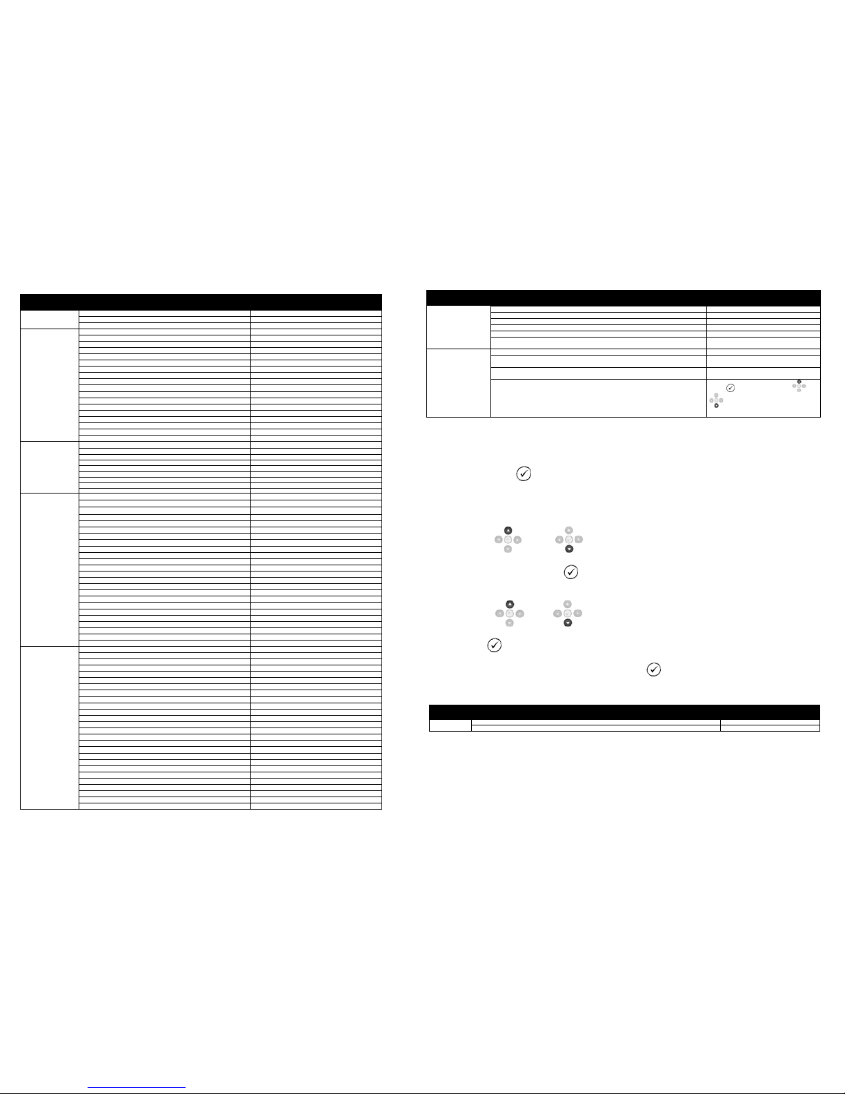
ACCESSING THE FRONT PANEL CONFIGURATION EDITOR.
•
Ensure the engine is at rest and the module is in STOP m ode by pressing the Stop/R eset button.
• Press the Stop/Reset and Info buttons simultaneously.
• If a module security PIN h as been set, the PIN number req uest is then
shown :
• Press the button the first digit will fl ash to enable the pin to be entered.
• Press
(up) or
(down to adjust it to the correct v alue)
• Press (right) when t he first digit is correctly enter ed. The digit you have just entered will now
show ‘#’ for security.
•
Repeat this process for th e other digits of the PIN number. You c an press (left) if you need to move
back to adjust one of the previous digits.
•
When is pressed aft er editing t he final PIN digit, the PIN is checked for validity. If the number is
not correct, you must re-ent er the PIN.
•
If the PIN h as been s uccessfully entered ( or the module PIN has not been
enabled), the editor is displ ayed :
EDITING A PARAMETER
• Enter the editor as described ab ove.
•
Press the or to cycle to the section you wish to view/change. Then pr ess
or
to cycle to the parameter within the section you have ch osen.
• To edit the parameter, press to enter edit mode. Th e parameter begins to fl ash to indicate that
you are editing the value.
• Press the up
or down buttons to change the parameter to the required valu e.
• Press to save the value. The parameter ceases fl ashing to indicate that it has been s aved.
• To exit the editor at any tim e, press and hold the
or button.
D E E P SE A E L E C T R O N I CS
7 4 20 IN S T A L LA TI O N I N ST RU C TI O NS
053-088
ISSUE 2
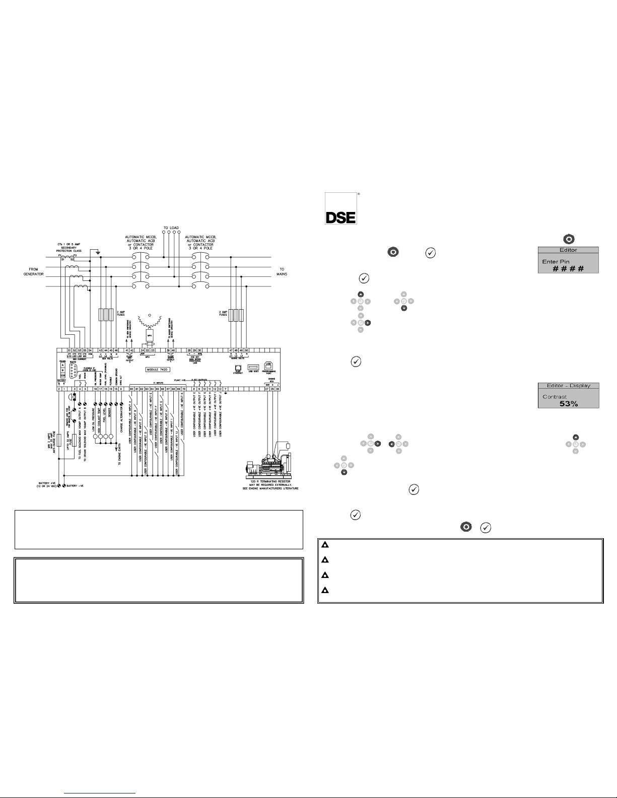
TYPICAL WIRING DIAGRAM
A larger diagram is available in the operators manual.
Deep Sea Electronics Plc.
Tel:+44 (0)1723 890099
Fax: +44 (0)1723 893303
Email: support@deepseaplc.com
Web: www.deepseaplc.com
Deep Sea Electronics inc.
Phone: +1 (815) 316-8706
Fax: +1 (815) 316- 8708
TOLL FREE (USA only) : Tel: 1 866 636 9703
Email: dsesales@deepseausa.com
Web: www.deepseausa.com
NOTE: When the editor is vi sible, it is automatically e xited after 5 minutes of in activity to
ensure security.
NOTE: The PIN number is automatically reset when the editor is exited (manual ly or
automatically) to ensure sec urity.
NOTE: More comprehensive module configuration is po ssible using the 86xx series PC
configuration software. Please contact us for further d etails
NOTE: The contents of the ta bles overleaf may differ d epending on the actual module
configuration.
DIMENSIONS AND MO UNTING
For flat surface mounting in a Type 1 enclosure.
DIMENSIONS
240.0mm x 181.1mm x 41.7 mm (9.4” x 7.1” x 1.6”)
PANEL CUTOUT:
220mm x 160mm (8.7” x 6.3”)
ADJUSTABLE PARAMETERS
Front Panel Configuration Editor
Section Parameter as shown on display Values
Display
Contrast 53%
Language
English, others.
Current Date and Time
hh:mm Timers
LCD Page Timer
5m
Scroll Delay
2s
Engine Pre Heat Timer
0s
Engine Crank Duration
10s
Engine Crank Rest Time
10s
Engine Safety On Delay
10s
Engine Smoke Limiting
0s
Engine Smoke Limiting Off
0s
Engine Warm Up Time
0s
Engine Cool Down Time
1m
Engine Speed Overshoot Delay
0s
Engine Failed To Stop
30s
Battery Under Voltage Warning Delay
1m
Battery Over Voltage Warning Delay
1m
Return Delay
30s
Generator Transient Delay
0s
Mains Transient Delay
2s
Mains transfer time
0.7s Mains
Mains Under Voltage Alarm
184v
Mains Over Voltage Alarm
277v
Mains Under Frequency Alarm
45Hz Mains over Frequency Alarm
55Hz
Mains Transient Delay
2s
CT Primary
600A CT
Secondary 5A Mains k
W Rating 345kW Mains k
Var Rating
258kW
Generator
Under Voltage Shutdown
184v
Under Voltage Pre-Alarm 196v
Nominal Voltage 230v
Over Voltage Pre-Alarm 265v
Over Voltage Shutdown 277v
Under Frequency Shutdown 40Hz
Under Frequency Pre-Alarm 42Hz
Nominal frequency 50Hz
Over Frequency Pre-Alarm 54Hz
Over Frequency Shutdown 57Hz
Full Load Rating 500A
kW Overload Trip 100%
Delayed Over current Active
Delayed Over Current 100%
AC System 3 Phase 4 Wire
CT Primary 600A Power Cycle After Exit
CT Secondary 5A Power Cycle After Exit
Short Circuit Trip 200%
Earth CT Primary 500A
Earth Fault Trip Active
Earth Fault Trip 10%
Transient Delay 0s
Gen Reverse Power Delay 2s
Gen Reverse Power 35kW
Engine
Oil Pressure Low shutdown 1.03bar
Oil Pressure Low Pre-Alarm 1.24bar
Coolant Temp High Pre-Alarm 90ºC
Coolant Temp High Electrical Trip 92ºC (When Enabled)
Coolant Temp High Shutdown 95ºC
Start Delay Off load 5s
Start Delay on load 5s
Start Delay Telemetry 5s
Pre Heat Timer 0s
Crank Duration 10s
Crank rest Time 10s
Safety On Delay 10s
Smoke Limiting 0s
Smoke limiting off 0s
Warm Up Time 0s
Cool Down Time 1m
Speed Overshoot Delay 0s
Speed Overshoot 0%
Fail To Stop Delay 30s
Battery Under Volts Warning Active
Battery Under Volts Warning Delay 1m
Battery Under Volts Warning 10v
Battery Over Volts Warning Active
Battery Over Volts Warning Delay 1m
Battery Over Volts Warning 30v
Charge Alternator Failure Warning Active
Continued Overleaf
Front Panel Configuration Edit or (continued)
Section Parameter as shown on display Values
Engine (continued)
Charge Alternator Failure Warning
6.0v
Charge Alternator Warning Delay
5s
Charge Alternator Failure Shutdown
Ina
ctive
Charge Alternator Failure Shutdown
4.0v
(When Enabled)
Charge Alternator Shutdown Delay
5s
(When Enabled)
Droop %
Active, Inactive. Electronic engines only when
droop is enabled.
Scheduler
Scheduler
Active,
Inactive
Schedule On Load
Active , Inactive (Only Available When
Scheduler Is Active)
Schedule Period
Weekly, Monthly (Only Available When
Scheduler Is Active)
Schedule Time & Date Selection (1-16)
Press to begin editing then or
when selecting the different
parameters in the scheduler.
ACCESSING THE ‘RUNNING’ CONFIGURATION EDITOR
• The ‘running’ editor can be entered while the engine is ru nning. All protections remain active if the
engine is running while the r unning editor is entered.
• Press and hold the
button to enter the running editor.
ADJUSTABLE PARAMETERS (Running editor)
• Enter the editor as described ab ove.
•
Press the up or down buttons to cycle to the secti on you wish to view/ch ange.
•
To Edit the parameter press th e button to enter edit mode. The parameter begins to flash t o
indicate that you are editing t he value.
• Press the up
or down
buttons to change the paramet er to the required value.
• Press the button to save the value. The parameter ceases fl ashing to indicate that it has been
saved.
• To exit the editor at any time , press and hold the button.
Running Editor
Section Parameter as shown on display Factory Settings
DISPLAY Contrast 53%
Language
English
 Loading...