

Page 1
053-060
ISSUE 1
DEEP S EA E L E CT R O NI C S
DSE6120 Installation Instructions
ACCESSING THE FRONT PANEL EDITOR (FPE)
The module must be in STOP mode with the engine at rest before configuration mode can be accessed.
To enter the ‘configuration mode’ press both the INFO and STOP buttons together.
ENTERING THE CONFIGURATION EDITOR PIN NUMBER
If the module PIN number has been set, the PIN number request is then shown. The configuration
cannot be viewed or changed until the PIN number is correctly entered.
• The first * is flashing. Press + or – buttons to adjust it to the correct value for the first digit of
the PIN number.
• Press when the first digit is correctly entered.
• The entered digit will turn back to a * to maintain security.
• Enter the remaining digits of the pin number using the same method.
If the Configuration PIN has been entered successfully (or the PIN number has not been set in the module) the first
configurable parameter is displayed.
NOTE:- When is pressed after editing the final PIN digit, the PIN is checked for validity. If the number is not
correct, the editor is automatically exited. To retry you must re-enter the editor as described above
.
EDITING A PARAMETER
Enter the editor as described above.
• Press to select the required ‘page’ as detailed below.
• Press (+) to select the next parameter or (-) to select the previous parameter within the current page.
• When viewing the parameter to be changed, press the () button. The value begins to flash.
• Press (+) or (-) to adjust the value to the required setting.
• Press () the save the current value, the value ceases flashing.
• Press and hold the () button to exit the editor.
.
NOTE: -
Values representing pressure will be displayed in Bar. Values representing temperature are displayed in
degrees Celsius
.
NOTE: - When the editor is visible, it is exited after 5 minutes of inactivity to ensure security.
NOTE:- To exit the front panel configuration editor at any time, press and hold the () button. Ensure you
have saved any changes you have made by pressing the button first.
NOTE:- The PIN number is automatically reset when the editor is exited (manually or automatically) to ensure
security.
Deep Sea Electronics Plc.
Tel:+44 (0)1723 890099
Fax: +44 (0)1723 893303
LO CALL (from UK BT landlines)
Telephone 0845 260 8933
Email: support@deepseaplc.com
Web: www.deepseaplc.com
Deep Sea Electronics inc.
Phone: +1 (815) 316-8706
Fax: +1 (815) 316- 8708
TOLL FREE (USA only) :
Tel: 1 866 636 9703
Email: dsesales@deepseausa.com
Web: www.deepseausa.com
Deep Sea Electronics Plc.
(Far East)
Tel:+66 2 670 6228
Fax: +66 2 678 3028
Email: support@deepseaplc.com
Web: www.deepseaplc.com
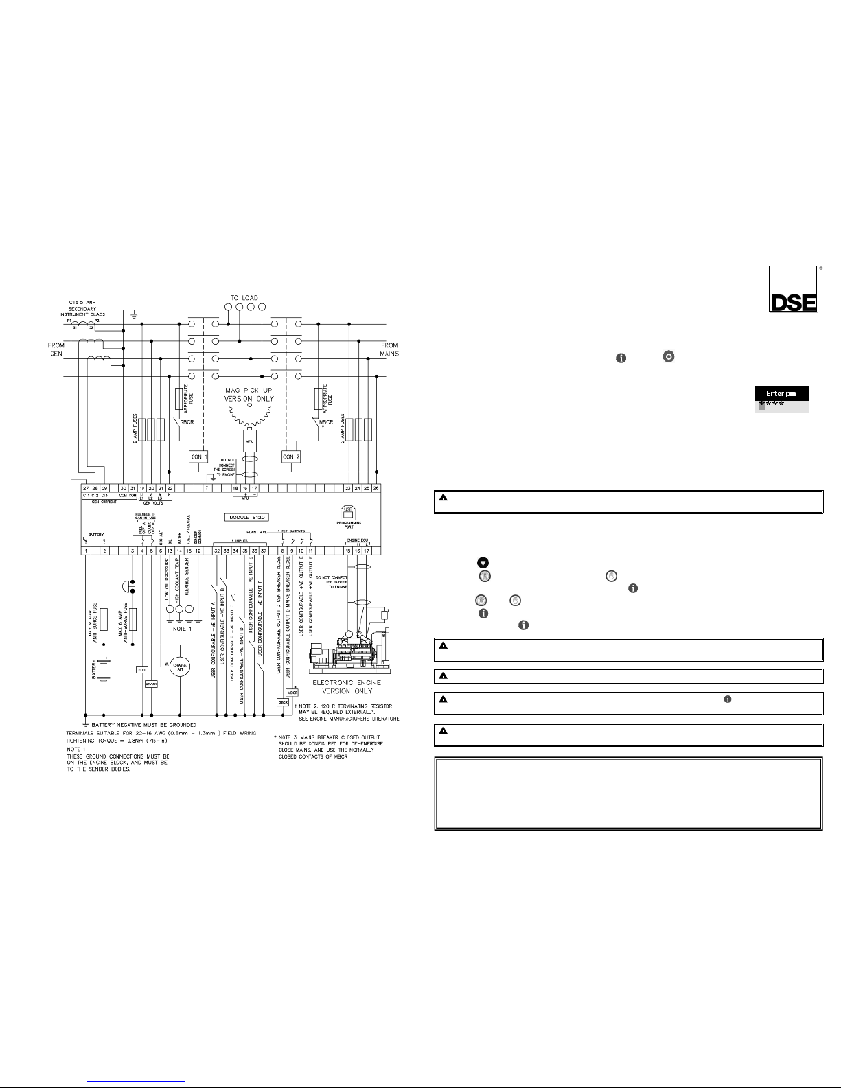
T
ypical Wiring Diagram
Page 2
ADJUSTABLE PARAMETERS (Configuration editor)
(Factory default settings are shown in bold italicised text)
Section
Parameter as shown on display
Values
PIN
Pin Entry
# # # #
DISPLAY
Contrast
0% - 100% (53%)
Language English - Others
LCD Page Timer
hh:mm:ss (5m)
Auto Scroll Delay
1s - 1hr (2s)
ALT CONFIG
Default Config
Default Config
ENGINE
Oil Pressure Low Shutdown
0bar - 9.97bar (1.03bar)
Coolant Temperature High Shutdown 2ºC - 140ºC (95ºC)
Start Delay Timer
0 - 10hr (5s)
Pre Heat Timer
0 - 5m (0s)
Crank Duration Timer
0 - 1m (10s)
Crank Rest Timer
0 - 1m (10s)
Safety On Delay 0 - 1m (10s)
Smoke Limiting
0 - 15m (0s)
Smoke Limiting Off
0 - 1m (0s)
Warm Up Timer
0 -1hr (0s)
Cool Down Timer
0 - 1hr (1m)
Speed Low Shutdown Active, Inactive
Speed Low Shutdown
0RPM - 6000RPM (1270RPM)
Speed High Shutdown
0RPM - 6000RPM (1740RPM)
Speed Overshoot Delay
0-10s (2s)
Speed Overshoot
0% - 10% (0s)
Fail To Stop Delay 0 - 2m (30s)
Battery Voltage Low Warning
Active, Inactive
Battery Low Voltage
0V – 40V (10V)
Battery voltage Low Warning Delay
0 - 24hr (1m)
Battery Voltage High Warning
Active, Inactive
Battery Voltage High Warning Delay 0V - 24hr (1m)
Battery Voltage High Warning
0V – 40V (30V)
Charge Alternator Failure Warning
Active, Inactive
Charge Alternator Failure Warning
0V – 39V (6V)
Charge Alternator Failure Warning Delay
0 - 24hr (5s)
Charge Alternator Failure Shutdown Active, Inactive
Charge Alternator Failure Shutdown
0V – 5.9V (4.0V)
Charge Alternator Failure Shutdown Delay
0 - 24hr (5s)
GENERATOR
Voltage Low Shutdown
50V – 360V (184V)
Voltage Nominal
50V – 276V (230V)
Voltage High Shutdown 231V – 360V (277V)
Frequency Low Shutdown
0Hz - 75Hz (43Hz)
Frequency Nominal
0Hz - 75Hz (50Hz)
Frequency High Shutdown
0Hz - 75Hz (58Hz)
Full Load Rating
5A – 6000A (500A)
Delayed Over Current Active, Inactive
Delayed Over Current
50% - 120% (100%)
AC System Single Phase, 2 Wire
3 Phase, 4 Wire
3 Phase, 4 Wire3 Phase, 4 Wire
3 Phase, 4 Wire
2 Phase, 3 Wire (L1 & L3)
3 Phase, 4 Wire (Delta)
2 Phase, 3 Wire (L1 & L2)
3 Phase, 3 Wire
CT Primary
5A - 6000A (600A)
Generator Transient Delay
0 - 10m (0.7s)
ront Panel Configuration Editor
(Factory default settings are shown in bold italicised text)
Section Parameter as shown on display
Values
MAINS Voltage Low Trip 50V – 360V (184V)
Voltage High Trip 50V – 360V (276V)
Frequency Low Trip 0Hz - 75Hz (45Hz)
Frequency High Trip 0Hz - 75Hz (55Hz)
Mains Transient Delay 0 - 30s (2s)
Return Delay 0 - 1hr (30s)
Mains Transfer Time 0 - 10m (0.7s)
TIMERS
LCD Page Timer
hh:mm:ss (5m)
Auto Scroll Delay
1s - 1hr (2s)
Pre Heat Timer 0 - 5m (0s)
Crank Duration Timer
0 - 1m (10s)
Crank Rest Timer
0 - 1m (10s)
Safety On Delay
0 - 1m (10s)
Smoke Limiting
0 - 15m (0s)
Smoke Limiting Off
0 - 1m (0s)
Warm Up Timer
0 -1hr (0s)
Cool Down Timer
0 - 1hr (1m)
Fail To Stop Delay
0 - 2m (30s)
Battery voltage Low Warning Delay
0 - 24hr (1m)
Battery Voltage High Warning Delay 0V - 24hr (1m)
Return Delay 0 - 5hr (30s)
Generator Transient Delay 0.1s - 2m (30s)
Mains Transient Delay 0 - 30s (2s)
Mains Transfer Time 0 - 10m (0.7s)
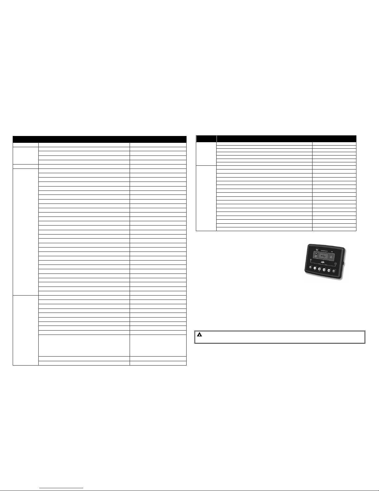
DIMENSIONS AND MOUNTING
DIMENSIONS
216mm x 158mm x 42mm
(8.5” x 6.2” x 1.6”)
PANEL CUTOUT
182mm x 137mm
(7.2” x 5.4”)
1.1.1 WEIGHT
510g (0.51kg)
1.1.2 FIXING CLIPS
The module is held into the panel fascia using the supplied fixing clips.
• Withdraw the fixing clip screw (turn anticlockwise) until only the pointed end is protruding from the clip.
• Insert the three ‘prongs’ of the fixing clip into the slots in the side of the 6000 series module case.
• Pull the fixing clip backwards (towards the back of the module) ensuring all three prongs of the clip are
inside their allotted slots.
• Turn the fixing clip screws clockwise until they make contact with the panel fascia.
• Turn the screws a little more to secure the module into the panel fascia. Care should be taken not to over
tighten the fixing clip screws.
NOTE:- In conditions of excessive vibration, mount the panel on suitable
anti-vibration mountings.
 Loading...