

Page 1

AUTOMATIC TRANSFER SWITCH
PANEL (ATS) DSE 333
1 Phase 230V
3 Phase 400V
OPERATION AND MAINTENANCE
Stephill Generators Ltd
Wallis close
Park Farm South
Wellingborough
Northants
NN8 6AG
Tel : +44 (0)1933 677911
Fax: +44 (0)1933 677916
E-mail : info@stephill-generators.co.uk
Web : www.stephill-generators.co.uk
Issue 2
Page 2

CONTENTS
Page
1.0
SAFETY
1
2.0
INSTALLATION
1
2.1
ELECTRICAL INSTALLATION
1
2.2
AC WIRING
1
2.3
DC WIRING
1
3.0
START GUIDE
1-2
3.1
DISPLAY PAGES
3
3.2
STATUS
3
3.2
INSTRUMENTATION
3
3.4
ALARMS
3
3.5
EVENT LOG
4
3.6
LCD INDICATORS
4
3.7
SCHEDULE
4
4.0
CONTROLS
4
4.1
MODE SELECTION
4
5.0
DISPLAY
5
5.1
LOAD SWITCHING CONTROL
5
6.0
OPERATION
5
6.1
AUTOMATIC MODE OF OPERATION
5
6.1.1
WAITING IN AUTO MODE
5
6.1.2
STARTING SEQUENCE
5
6.1.3
GENERATOR ON LOAD
5
6.1.4
STOPPING SEQUENCE
6
6.2
MANUAL OPERATION
6
6.2.1
STARTING SEQUENCE
6
6.2.2
GENERATOR OFF LOAD
6
6.2.3
GENERATOR ON LOAD
6
6.2.4
TRANSFER BUTTONS OPERATION
6
6.2.5
STOPPING SEQUENCE
6
6.3
TEST ON LOAD OPERATION
7
6.3.1
STARTING SEQUENCE
7
6.3.2
GENERATOR ON LOAD
7
6.3.3
STOPPING SEQUENCE
7
7.0
MODULE DISPLAY
7
7.1
BACKLIGHT
7
7.2
PROTECTIONS
7
7.2.1
GENERATOR
7
7.2.2
MAINS
8
7.3
PLANT BATTERY
8
8.0
SYSTEM TEST
8
9.0
FRONT PANEL CONFIGURATION
8
9.1
ACCESSING THE FRONT PANEL EDITOR (FPE)
9
9.2
EDITING A PARAMETER
9
9.3
ADJUSTABLE PARAMETERS (CONFIGURATION EDITOR)
9
9.4
SCHEDULER SETTING
10
10
CHECK LIST FOR AUTOMATIC OPERATION
10
11
WARRANTY
10
1 PHASE ATS WIRING (STEPHILL)
11
1 PHASE ATS WIRING 100A+ (ATS)
12
3 PHASE ATS WIRING DSE 333 (ATS)
13
3 PHASE ATS WIRING DSE 333 (STEPHILL)
14
ATS – GENERATOR – MAINS INTERCONNECTION WIRING DSE 333
15
Issue 2
Page 3

1 SAFETY
Warning
ATS Panel should only be installed, maintained or serviced by a qualified electrician.
The generator set may start without warning whilst in AUTO mode.
Before undertaking any service or maintenance work, ensure the mains and generator supply are
isolated and generator is switched to off.
The generator is supplied with the battery disconnected/isolated for safety reasons and should not
be re-connected until all connections have been made.
Because of the nature of the equipment and the permanent mains connection, the terminals within
the generator may be LIVE even if the generator itself is not running.
2 INSTALLATION
Make sure that the Generator is at least one metre away from any building during operation.
Operate in a well ventilated unconfined area, so that fumes can be properly dispersed.
Silencer outlet should be facing an open area to prevent fumes being recirculated.
Consideration will also need to be made for refuelling and maintenance.
If installing in a confined area please consult manufacturer.
2.1 ELECTRICAL INSTALLATION
2.2 AC Wiring
Please ensure the correct cross sectional area of cable between the Alternator/Panel and
Distribution board used is adequate to carry the full rated continuous output of the generator,
allowing for de-rating in high ambient temperatures. Please consult IEE regulations as per the
correct sizing of cable and other issues regarding wiring. Flexible cable is recommended for
alternator connections allowing for a generous loop before the cable enters the alternator terminal
box because of the vibration caused by the set starting. If this is not possible a terminal box can be
fitted nearby and flex fitted between this and the generator terminal box. These precautions will not
be needed when fixing to a control box which is not attached to the Alternator. Please refer to
Wiring diagram.
2.3 DC WIRING
For the DC wiring we recommend 1.5mm if the generator is more than 10Meters away please
consult manufacturer for cable sizing. Please refer to Wiring diagram.
3 START GUIDE
Note For full instructions download handbook on DSE website http://www.deepseaplc.com/home/
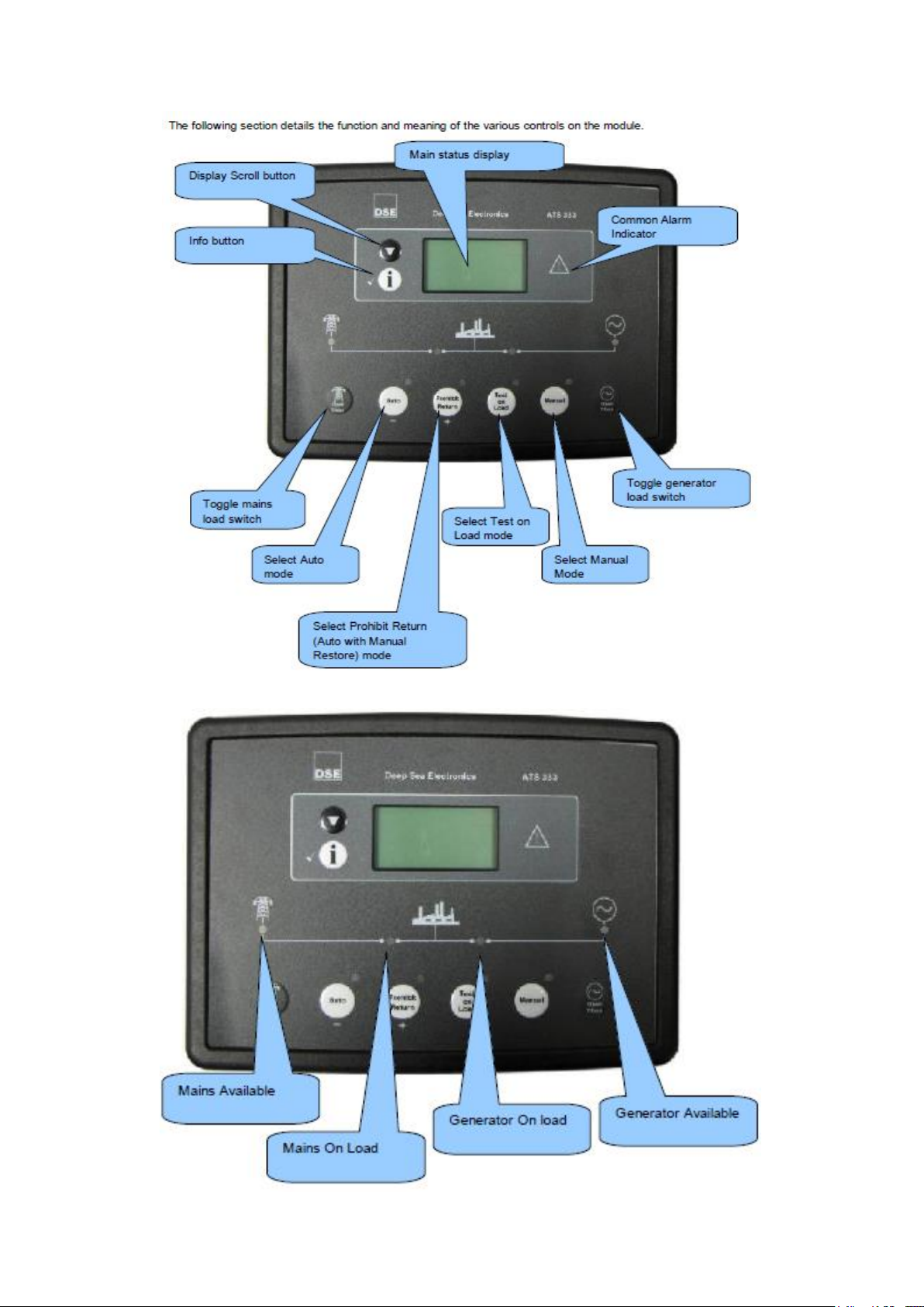
This section provides a quick start guide to the module’s operation.
Issue 1 1
Page 4
Issue 1 2
Page 5
3.1 DISPLAY PAGES
It is possible to scroll to display the different pages of information by repeatedly operating the scroll
button
Once selected the page will remain on the LCD display until the user selects a different page or after
an extended period of inactivity, the module will revert to the status display.
When scrolling manually, the display will automatically return to the Status page if no buttons are
pressed for the duration of the configurable LCD Page Timer.
If an alarm becomes active while viewing the status page, the display shows the Alarms page to draw
the operator’s attention to the alarm condition.
At power up, the display will show the software version, and then display the default display screen,
which will display Mains instrumentation.
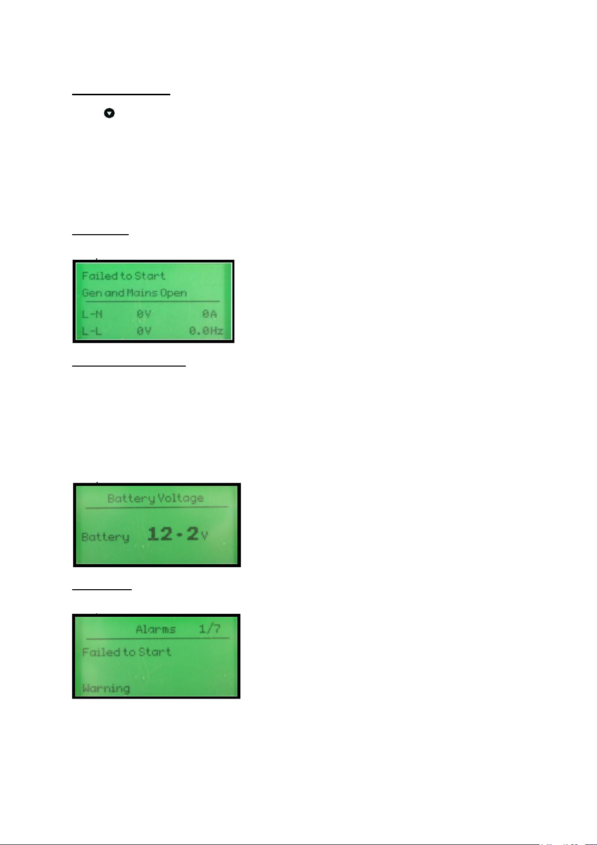
3.2 STATUS
Displays voltage operational status information
Example:
3.3 INSTRUMENTATION
The instrumentation page contains the following information
Generator Voltage L1-N
Generator Voltage L-L
Generator Frequency
Mains Voltage L1-N
Mains Voltage L-L
Mains Frequency
Load current (A)
Battery Voltage Example:
3.4 ALARMS
Lists any current alarms
Example
Issue 1 3
Page 6

This button places the module into its ‘Automatic’ mode. This mode allows the module to
control the function of the load switching completely automatically. The module will
monitor the remote start input and mains supply status and once a start request is
made, the set will be placed on load.
Upon removal of the starting signal (or the mains supply returns), the module will
automatically transfer the load from the generator to the mains and remove the genset
starting instruction.
For further details, please see the more detailed description of ‘Auto operation’
elsewhere in this manual.
Operation is as AUTO MODE above but the load is not transferred back to the mains
supply when it is reinstated. This function is sometimes called “MANUAL RESTORE”
Once in Test on load mode the module will send a start request to the generator and
place the set on load. The set will remain on load when in this mode.
This mode allows manual control of the ATS functions. Once in Manual mode the
module will send a start request to the generator.
Breakers can be opened and closed using the transfer buttons detailed below.
3.5 EVENT LOG
Displays the entire event log
Example:
3.6 LCD INDICATORS
Shows the status of the configurable LCD indicators
Example:
3.7 SCHEDULE
Shows the settings of the exercise scheduler
Example:
4.0 CONTROLS
4.1 MODE SELECTION
Issue 1 4
Page 7

This button changes between the various pages About, Status, Instrumentation, Alarms,
Event Log, LCD Indicators
This buttons scrolls through the items in the currently displayed page.
Pressing this button when the mains is on load will open the mains load switch. Pressing
this button when the generator is on load and the mains is healthy, will open the
generator load switch, wait for the duration of the transfer delay, then close the mains
load switch.
Pressing this button when the generator is on load will open the generator load switch.
Pressing this button when the mains is on load and the generator is available, will open
the mains load switch, wait for the duration of the transfer delay, then close the
generator load switch.
5.0 DISPLAY
5.1 LOAD SWITCHING CONTROL
Two fascia mounted buttons are provided for load switching operation when in manual mode. These
buttons are enabled/disabled in the modules PC configuration Suite so refer to your configuration file
to ensure the configuration has enabled the buttons.
6 OPERATION
6.1 AUTOMATIC MODE OF OPERATION
Activate auto mode by pressing the Auto pushbutton.
Auto mode will allow the transfer system to operate fully automatically, starting and stopping the
generator as required with no user intervention.
6.1.1 WAITING IN AUTO MODE
If a starting request is made and there is no input present for Auto Start Inhibit, the starting sequence
will begin.
Starting requests can be from the following sources:
Mains failure
Activation of an auxiliary input that has been configured to remote start
Activation of the inbuilt exercise scheduler.
6.1.2 STARTING SEQUENCE
To allow for ‘false’ start requests, the start delay timer begins.
Should all start requests be removed during the start delay timer, the unit will return to a stand-by
state.
If a start request is still present at the end of the start delay timer, start signal is given to the generator
set by the start/run output.
If the generator fails to become available before the generator failure timer expires. This is indicated
on the LCD display, but the starting signal remains active.
6.1.3 GENERATOR ON LOAD
Once the generator is measured as being within limits (and the Auxiliary Generator Ready signal is
received, the mains is removed from the load, and after the transfer timer has expired, the generator
is placed on load.
If all start requests are removed and there is no input present for Auto Restore Inhibit, the stopping
sequence will begin.
Issue 1 5
Page 8

Pressing this button when the mains is on load will open the mains load switch.
Pressing this button when the generator is on load and the mains is healthy, will
open the generator load switch, wait for the duration of the transfer delay, then
close the mains load switch.
Pressing this button when the generator is on load will open the generator load
switch. Pressing this button when the mains is on load and the generator is
available, will open the mains load switch, wait for the duration of the transfer
delay, then close the generator load switch.
6.1.4 STOPPING SEQUENCE
The return delay timer operates to ensure that the starting request has been permanently removed
and isn’t just a short term removal.
After the return delay timer, the generator load switch is opened, then after the transfer timers, the
mains is placed back on load.
Should another start request be made during the cooling down period, the generator will be placed on
load.
The cooling timer allows the set to run off load and cool sufficiently before being stopped. This is
particularly important where turbo chargers are fitted to the engine.
After the cooling timer has expired, the set is stopped.
6.2 MANUAL OPERATION
Manual mode allows the operator to start and stop the set manually, and if required change the state
of the load switching devices. Manual off load mode is active when the Manual button is pressed.
6.2.1 STARTING SEQUENCE
The start request is sent to the generator via the start/run relay output.
If the generator fails to become available before the generator failure timer expires. This is indicated
on the LCD display, but the starting signal remains active.
6.2.2 GENERATOR OFF LOAD
The generator will continue run OFF LOAD in this mode unless:
The mains supply fails
An input is given for Auxiliary Mains Failure
An input is given for Transfer to Generator
The fascia mounted transfer buttons are pressed (when configured)
6.2.3 GENERATOR ON LOAD
Once on load, the generator will remain on load unless:
An input is given for Transfer to Mains
The fascia mounted transfer buttons are pressed (when configured)
The module mode is changed to STOP\RESET or AUTO mode. The system may then transfer back
to mains supply automatically if conditions are suitable.
6.2.4 TRANSFER BUTTONS OPERATION
Two fascia mounted buttons are provided for load switching operation when in manual mode.
6.2.5 STOPPING SEQUENCE
The set will not be stopped in this mode of operation.
To begin the stopping sequence, the module should be placed in the AUTO or PROHIBIT RETURN
mode.
Issue 1 6
Page 9

6.3 TEST ON LOAD OPERATION
Manual mode allows the operator to start and stop the set manually, and if required change the state
of the load switching devices. Manual off load mode is active when the Test on Load button is
pressed.
6.3.1 STARTING SEQUENCE
The start request is sent to the generator via a digital output configured to Start and Run S2.
If S2 fails to become available before S2 fail delay timer expires. This is indicated on the LCD display,
but the starting signal remains active.
6.3.2 GENERATOR ON LOAD
The Generator will continue to run ON LOAD in this mode unless:
The generator supply fails – The mains supply is placed back on load if available.
An input is given for Transfer to Mains
6.3.3 STOPPING SEQUENCE
The set will not be stopped in this mode of operation.
To begin the stopping sequence, the module should be placed in the AUTO or PROHIBIT RETURN
mode.
7 MODULE DISPLAY
7.1 BACKLIGHT
The backlight will be on if the unit has sufficient voltage on the power connection while the unit is
turned on.
7.2 PROTECTIONS
7.2.1 GENERATOR
The 333 ATS module monitors the generator supply to ensure that it remains within configured levels.
If the generator supply fails, it is taken off load and the start/run signal is to be removed.
Generator failure
The generator has not become available after the period of the Generator Failure timer has expired.
Generator Under Voltage shutdown
The generator supply is below the configured under voltage trip level
Generator Under Frequency shutdown
The generator supply is below the configured under frequency trip level
Failed to reach loading voltage
The generator is running and within under / over voltage trip points, but has failed to reach the
configured Loading Voltage, hence it is unfit to take load.
Failed to reach loading frequency
The generator is running and within under / over frequency trip points, but has failed to reach the
configured Loading Frequency, hence it is unfit to take load.
Issue 1 7
Page 10

7.2.2 MAINS
Mains alarms signal that the mains supply is out of limits. In AUTO mode, the generator is called to
start (if not already running) and will be placed on load when available.
If the mains supply fails while the generator is running in MANUAL mode, the 333 ATS module
transfers load to the generator supply.
Should an input configured to Simulate Mains Available be active, the mains failure detection is
inhibited.
Mains failure
Combined message to indicate the failure of the mains supply or activation of an input configured to
Auxiliary MainsFailure.
Mains Under Frequency trip
The mains supply is below the configured Under Frequency trip level.
Mains Under Voltage trip
The mains supply is below the configured Under Voltage trip level.
Mains Over Frequency trip
The mains supply is above the configured Over Frequency trip level.
Mains Over Voltage trip
The mains supply is above the configured Over Voltage trip level.
7.3 PLANT BATTERY
Plant battery alarms are Warning alarms only. The module displays the fault but no further action is
taken.
Under Voltage warning
The battery supply is below the configured Under Voltage warning level.
Under Voltage warning
The battery supply is above the configured Over Voltage warning level.
8 SYSTEM TEST
It is recommended that the generator is tested every week and run on load for 30 minutes.
9 FRONT PANEL CONFIGURATION
This configuration mode allows the operator limited customising of the way the module operates.
Use the module’s navigation buttons to traverse the menu and make value changes to the
parameters:
Issue 1 8
Page 11

Page
Parameter as shown on
Values
DISPLAY
Contrast 0% - 100%
(53%)
Language
English - Others
Current date and time
Date month year hh:mm:ss
GENERATOR
Under Voltage Trip
50V – 360V (208V)
Under Frequency Trip
0Hz - 75Hz (45Hz)
MAINS
Immediate mains dropout
Active,Inactive
Under Voltage Trip
50V – 360V (208V)
Over Voltage Trip
50V – 360V (260V)
Under Frequency Trip
0Hz - 75Hz (45Hz)
Over Frequency Trip
0Hz - 75Hz (55Hz)
TIMERS
Warm Up Time
0 -1hr (1s)
Start Delay
0 - 10hr (5s)
Mains Transient Delay
0 - 30s (2s)
Generator Failed Delay
0 - 1m (60s)
Elevator Delay
0 – 5m (0s)
Non sync Transfer Time
1 – 10m (0.7s)
Check-sync Transfer Time
1 – 10m (0.2s)
Return Delay
0 - 5hr (30s)
Cool Down Timer
0 - 1hr (3m)
Generator Transient Delay
0 - 30s (5s)
Fail to Stop Delay
0 – 2m (30s)
Scroll Delay
0 – 1hr (5s)
Page Timer
0 – 1hr (5m)
SCHEDULE
Schedule
Active, Inactive
Schedule On Load
Active, Inactive (only available
when Scheduler is active)
Schedule Period
Weekly, Monthly (only available
when Scheduler is active)
Schedule time and date selection
(1-16)
Press when editing to select
the different parameters within
the scheduler.
9.1 ACCESSING THE FRONT PANEL EDITOR (FPE)
To enter the ‘configuration mode’ press both the DOWN and INFO buttons together.
9.2 EDITING A PARAMETER
Enter the editor as described above.
Press to select the required ‘page’ as detailed below.
Press + to select the next parameter or - to select the previous parameter within the current page.
When viewing the parameter to be changed, press the button. The value begins to flash.
Press + or - to adjust the value to the required setting.
Press to save the current value, the value ceases flashing.
Press and hold the button to activate the changes you have made and exit the editor.
9.3 ADJUSTABLE PARAMETERS (CONFIGURATION EDITOR)
When viewing the configuration editor, Press to select the required ‘page’ as listed below.
Front Panel Configuration Editor (Factory default settings are shown in bold italicised text)
Parameter as shown on
Issue 1 9
Page 12

Enter the editor as described above and press the button to access
the Scheduler page.
Press to enter edit mode and use the + / i buttons to make the
Schedule function active.
Press to save your change.
Press + to move to the next item.
Review the current setting and choose if the Scheduler is to perform an
‘on load’ test (active) or ‘off load’ test (inactive)
Press + to move to the next item.
Review the current setting and choose if the Scheduler is to perform a
weekly schedule (repeats every 7 days) or monthly (repeats every 28
days)
Press + to move to the next item.
Press to select which schedule entry to edit (there are up to 16
entries indicated by the number in the tope left corner)
Press to edit the schedule. The item being edited flashes.
Press + / - to change the flashing item.
Press to move to the next editable value. (On, Day, Run Time etc)
Press to save your change
9.4 SCHEDULER SETTINGdi
spay
ues
10 CHECK LIST FOR AUTOMATIC OPERATION
1. Auto mode selected on DSE333.
2. Generator output MCB & RCD in on position.
3. Generator in auto mode.
3. Battery charger switched on.
11 WARRANTY
All equipment supplied by STEPHILL GENERATORS LTD carries a warranty
of 12 months from date of despatch.
During the warranty period, should the plant fail due to faulty design, materials or workmanship by
STEPHILL or its sub-contractors, we undertake to rectify the fault by replacement or repair at our
option.
STEPHILL will accept no responsibility whatsoever for equipment that has failed due to;
- Improper repair or use of parts not supplied by STEPHILL.
- Lack of, or incorrect maintenance.
- Fair wear and tear, misuse, negligence, accidental damage, improper
storage, incorrect starting / warm-up / run-in or shutdown.
No warranty claim will be considered by STEPHILL unless any defective parts are available for
inspection by us, or our nominees, to determine the reason or cause of failure, and STEPHILL is
given the option of repair or replacement.
STEPHILL are not responsible for incidental or consequential damages, downtime, or other costs due
to warrantable failure, and unauthorised alterations made to any product supplied by STEPHILL.
Issue 1 10
Page 13

CT COMMON MUST BE
CONNECTED TO THE SAME
GROUND AS BATTERY NEGATIVE
LOAD
N
L1
34
37
37
GENERATOR
S2
GENERATOR
29
29
GCC
29
29282726
NL3L2L1
CONTACTOR
38
29
MECHANICAL INTERLOCK
29
42
4224
MC
ELECTRICAL INTERLOCK
26
25 24
GENERATOR
LOADING RELAY
OUTPUT B
24
38
L
29
N
1.5mm Black
34
LOAD CURRENT
1.5mm Black
37
37363534
COMCT3CT2CT1
38
3826
F4 2A
26
26
GEN VOLTS
DSE 333 ATS
MAINS
CONTACTOR
MCC
41
GC
23 41
30
23
2223
MAINS
LOADING RELAY
OUTPUT A
33
33
NE L
39
33
F3 2A
3343
ON / OFF
43 44 3943 44
39
33
33
39
33
F5 2A
30 39
30
30
MAINS VOLTS
33
33
33
323130
NL3L2L1
39
L
33
MAINS
S1
N
BATTERY
CHARGER
+
OUTPUT D
OUTPUT C
-VE
+VE
2
1
1
4
OUTPUT E
A B C D E F G H I J
11 12 13 14 15 16 17 18 19 201 2 3 4 5 6 7 8 9 10
10 -VE INPUTS
21
-
1
3
LEGEND
= GENERATOR CONTACTOR
GC
= GENERATOR CONTACTOR COIL
GCC
= MAINS CONTACTOR
MC
= MAINS CONTACTOR COIL
MCC
STEPHILL GENERATORS
Phone 01933 677911
Fax 01933 677916
Drawing Number
SW180014
Drawn
R Golding
2
F1 2A
3
1
Description
1 Phase ATS Panel DSE 333
Last Number Used
45
MC
14
1
1
Issue
GC
1 15
4 REMOTE START
1
Revision
Date
A
03-04-14
B
05-02-16
New drawing
Fuse removed from battery charger.
1
3
1 BATTERY -VE
3 BATTERY +VE
Page 14

GENERATOR
SUPPLY
LOAD
NL
113
110
MCGC
L
101
201201
L
MAINS
SUPPLY
N
GENERATOR
D.C. CONTROL
REMOTE
START
BATTERY
-VE
-VE
+VE
104
F3
2A
105
113
110
35
34
CT2 CT336COM
CT1
LOAD CURRENT
OUTPUT
C
3
4
10
4
1
4
105
37
26
V W
U
GEN VOLTS
12
20
F4
2A
1
3
104
292827
N
CLOSE GEN
5 9 11 12
NOT USED
1
-VE
BATTERY
CHARGER
3
+VE
104
A2
109 209
MC
105
108
24
25
B
7 86
L
Mechanical Interlock
222117
MC GC
1
211
13 14 15 16 17 18 19 20
OFF/ON
SUPPLY ON
204
N
210
GC
NOT USED
F2
2A
204
A2
A1A1
205
208
22
23
A
CLOSE MAINS
201
F1
2A
205
205
30 31 32 33
MAINS VOLTS
204
204
NTSR
204
N
STEPHILL GENERATORS
Phone 01933 677911
Fax 01933 677916
Drawing Number
SW180017
Drawn
R Golding
Description
1 Phase ATS Panel DSE 333 100A +
Last Number Used
209
Issue
A
Date
20-11-15
Revision
New drawing
Page 15

LOAD
NL3L2L1
113
110
111
113
112
MCGC
L1
101
201
201
L1
GENERATOR
SUPPLY
BATTERY
L2
L3
GENERATOR
D.C. CONTROL
REMOTE
-VE
START
-VE
+VE
204
L2
MAINS
SUPPLY
L3
NN
102
103
104
F5
2A
105
112
111
110
35
34
CT2 CT336COM
CT1
LOAD CURRENT
OUTPUT
C
3
4
4
4
113
105
37
26
U
12
20
1
F8
2A
1
3
F7F6
2A
2A
107
106
104
107
106
292827
V W
GEN VOLTS
5 9 11 12
N
CLOSE GEN
7 8610
NOT USED NOT USED
1
-VE
BATTERY
CHARGER
3
+VE
104
A2
Mechanical Interlock
GC
109 209
MC
105
108
24
25
B
13 14 15 16 17 18 19 20
22211
MC GC
1
211
L
204
N
OFF/ON
SUPPLY ON
210
F4
2A
204
A2
MC
A1A1
GC
208
23
A
CLOSE MAINS
201
204
205
22
202
203
F1
F22AF3
2A
205
205
30 31 32 33
MAINS VOLTS
206
206
2A
207
207
204
204
NTSR
STEPHILL GENERATORS
Phone 01933 677911
Fax 01933 677916
Drawing Number
SW180016
Drawn
R Golding
Description
3 Phase ATS panel DSE 333
Last Number Used
209
Issue
A
Date
20-11-15
Revision
New drawing
Page 16

GENERATOR
S2
CT COMMON MUST BE
CONNECTED TO THE SAME
GROUND AS BATTERY NEGATIVE
37
37
37
48
L1
49 49
L2
50 50
L3
29
N
48
49
50
GENERATOR
CONTACTOR
48
29
29
LOAD
L1
L2
34
37
35
37
36
37
L3
N
MAINS
CONTACTOR
39
33
39
4646
4747
33
33
39
33
33
39
L1
46
L2
47
33
MAINS
S1
L3
N
LEGEND
= GENERATOR CONTACTOR
GC
= GENERATOR CONTACTOR COIL
GCC
= MAINS CONTACTOR
MC
= MAINS CONTACTOR COIL
MCC
STEPHILL GENERATORS
Phone 01933 677911
Fax 01933 677916
Drawing Number
SW180018
Drawn
R Golding
4826
492727
F4 2A
F4 2A
1.5mm Black
1.5mm Black
34
35
LOAD CURRENT
-VE
2
1
2
F1 2A
3
1.5mm Black
36
OUTPUT C
+VE
1
1
1.5mm Black
37
37363534
COMCT3CT2CT1
4
26
26
GEN VOLTS
OUTPUT D
Description
3 Phase ATS Panel DSE 333
502828
F4 2A
29
29
GCC
42
4224
MC
29
29282726
NL3L2L1
GENERATOR
LOADING RELAY
DSE 333 ATS
OUTPUT E
Last Number Used
50
MECHANICAL INTERLOCK
ELECTRICAL INTERLOCK
26
24
25 24
OUTPUT B
A B C D E F G H I J
11 12 13 14 15 16 17 18 19 201 2 3 4 5 6 7 8 9 10
LOADING RELAY
14
MC
1
41
23 41
30
23
2223
MAINS
OUTPUT A
10 -VE INPUTS
GC
1 15
1
1
Issue
A
33
MCC
GC
Date
01-02-16
F5 2A
F5 2A
30 39
31 46
30
30
31
MAINS VOLTS
Revision
New drawing
F5 2A
32 47
32
323130
F3 2A
3343
ON / OFF
33
33
NL3L2L1
33
43 44 3943 44
NE L
BATTERY
CHARGER
+
-
1
3
21
4 REMOTE START
1
3
1 BATTERY -VE
3 BATTERY +VE
Page 17

ATS PANEL DSE333
GENERATOR
Cable to be sized as per iee regulations.
3 PHASE
BROWN
BLUE
1 PHASE
GREEN/YELLOW
U BROWN
V BLACK
W GREY
N BLUE
EARTH
L1
L2
L3
N
Cable to be sized as per Iee regulations.
L1
N N
L1
L2
L3
N
L1
BROWN
BLUE
GREEN/YELLOW
U BROWN
V BLACK
W GREY
3 PHASE
N BLUE
EARTH
1 PHASE
REMOTE START -VE
BATTERY -VE
BATTERY +VE
DC CONTROL
STEPHILL GENERATORS
Phone 01933 677911
Fax 01933 677916
4
1
3
Drawing Number
SW18015
Drawn
R Golding
Description
ATS - GENERATOR - MAINS
INTERCONNECTION WIRING
DSE 333
1.5mm (MAX 10M)
Last Number Used
47
DEEP SEA 3110
DEEP SEA 6110
4
(13) (32) (61) REMOTE START -VE
1
(1) (1) (1) BATTERY -VE
3
(2) (2) (2) BATTERY +VE
DEEP SEA 7310
DC CONTROL
DateIssue
A
01-04-14
B
19-11-15
Revision
New drawing
7310 Wiring added.
 Loading...