

Page 1
DF-C 63XXX & 61XXX Series User’s Manual
Version 28.04.2019
DSC-Electronics Germany • Georgstraße 36 • 53111 Bonn
DF-C 63XXX & 61XXX Series
AC Laboratory Power Supplies
User’s Manual
by DSC-Electronics Germany • Georgstraße 36 • 53111 Bonn
DSC-Electronics Germany • Georgstraße 36 • 53111 Bonn
Page 2
DF-C 63XXX & 61XXX Series User’s Manual
Version 28.04.2019
DSC-Electronics Germany • Georgstraße 36 • 53111 Bonn
1 Phase / EU Power Grid
Voltage (Recommended)
230V ± 10% AC
Voltage (Max.)
250V AC
Frequency
50Hz - 60Hz
Circuit breaker minimum requirements
The maximum current of the device shall be determined as
follows:
I = (maximum power of the device / 230) + 2
1 Phase / American Power Grid
Voltage (Recommended)
115V ± 10% AC
Voltage (Max.)
130V AC
Frequency
50Hz - 60Hz
Circuit breaker minimum requirements
The maximum current of the device shall be determined as
follows:
I = (maximum power of the device / 115) + 4
3 Phase / EU Power Grid (TN-S Network)
Voltage (Recommended)
380V - 410V
Voltage (Max.)
430V
Frequency
50Hz
Circuit breaker Minimum requirements
The maximum phase current of the device shall be
determined as follows:
I = ((maximum power of the device / 400) / 1,73) + 2
1. Connection
Our devices are pre-configured to the power grid chosen with order (if not specified otherwise, our devices are
manufactured for the EU power grid 230V 50Hz / 400V 50Hz). Subsequent adjustment after delivery is not possible.
Connecting the device to an unsuitable power source will void any warranty.
DSC-Electronics Germany • Georgstraße 36 • 53111 Bonn
Page 3
DF-C 63XXX & 61XXX Series User’s Manual
Version 28.04.2019
DSC-Electronics Germany • Georgstraße 36 • 53111 Bonn
WARNING
Identifies conditions or practices that could result in injury or loss
of life.
CAUTION
Identifies conditions or practices that could result in damage to the
instrument or to other properties.
DANGER
High Voltage
ATTENTION
Refer to the Manual
Protective Earth (PE)
Earth (Ground)
2. General
Please read through and understand this Operation Manual before operating the product. After reading always keep
the manual nearby so that you may refer to it as needed. When moving the product to another location, be sure to
bring the manual as well.
Calibration
Before shipment, the instrument has been calibrated carefully in our factory. The calibration procedures and
standards are compliant to the national regulations and standards for electronic calibration. If you have requested a
certificate with your order, this is enclosed with your device. With ordered off-site calibration (DaKKS) the calibration
was not performed in-house, please refer to the laboratory calibration protocol for details.
Warranty
We guarantee that the instrument has undergone a strict quality test before shipment and has passed all prescribed
functional tests. We provide our customers with a warranty period of three years from receipt of the device. During the
warranty period, all repairs, as well as spare parts are always free of charge. The warranty is void in the case of
defects which have been caused by user's fault, or in case of unauthorized opening.
2.1 Safety Instructions
This chapter contains important safety instructions that you must follow when operating the instrument and when
keeping it in storage. Read the following before any operation to insure your safety and to keep the device in a proper
condition.
Safety Symbols
The following safety symbols may appear in this manual or on the instrument:
DSC-Electronics Germany • Georgstraße 36 • 53111 Bonn
Page 4

DF-C 63XXX & 61XXX Series User’s Manual
Version 28.04.2019
DSC-Electronics Germany • Georgstraße 36 • 53111 Bonn
Before connecting the device to the local power supply, make sure that the device is switched off.
Check if the product is compatible with the local power supply before connecting it.
Be careful on the correct earthing of the device (PE connection)
Do not use the product in humid environments
Do not touch the output terminals of the product with unprotected hands while it is switched on.
Do not use the device in extremely dusty rooms
Do not use the device outside the parameters specified in the data sheet
2.2 Safety Guidelines
Please follow the safety guidelines when using and putting the device into operation in order to prevent safety risks
and to ensure the correct operation of the product.
2.3 Unpacking and Examination
Our products are delivered carefully packed in cardboard boxes or in wooden crates, depending on place of
destination and the type of the device (dimensions, weight). We pay attention to the environmental compatibility of the
upholstery and packaging materials used and ask you to dispose the filling material correctly if present.
Please unpack the device and check the packaging as well as the product for transport damage. Should you notice
any damage to the packaging or the device, we ask you to log it with photos and inform us immediately.
ATTENTION: If the device has been delivered in a wooden box, please do not dispose it as it can be used for eventual
return transport for service procedures. Also the packaging material of smaller devices can be stored in order to be
used if necessary for a return transport.
DSC-Electronics Germany • Georgstraße 36 • 53111 Bonn
Page 5
DF-C 63XXX & 61XXX Series User’s Manual
Version 28.04.2019
DSC-Electronics Germany • Georgstraße 36 • 53111 Bonn
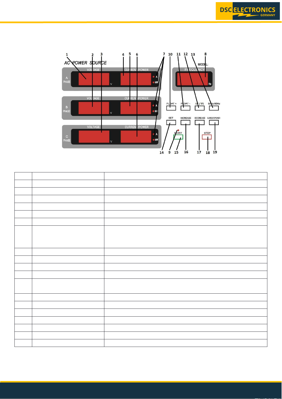
Nr.
Name
Description
1
Voltage Phase A
Voltage set or actual value of Phase A
2
Voltage Phase B
Voltage set or actual value of Phase B
3
Voltage Phase C
Voltage set or actual value of Phase C
4
Current / Power Ph. A
Current set or actual value of Phase A
5
Current / Power Ph. B
Current set or actual value of Phase B
6
Current / Power Ph. C
Current set or actual value of Phase C
7
Display Mode
Active „A“ LED indicates the current value
Active „kW“ LED indicates the power value
No active LED indicates the power factor value
8
Frequency
Output frequency „Hz“
9
Output On/Off Key
Indicates the output status
10
Float + Hot-Key
Higher the value by X percent
11
Float - Hot-Key
Lower the value by X percent
12
LV / FS Key
Switch between Low Voltage range (0 – 150V) and Full Scale range (0 –
300V)
13
Frequency Key
Fast switch between 50Hz / 60Hz
14
Setup Key
Output value setup
15
Start Key
Output ON
16
Increase Key
Higher the value
17
Decrease Key
Lower the value
18
Stop Key
Output OFF
19
Display Mode Switch Key
Toggle between Current, Power of Power Factor display
3. Operation Instructions
3.1 Front Panel Description 63XXX Series
Fig.1: Front Panel 63XXX Series (CV Version)
DSC-Electronics Germany • Georgstraße 36 • 53111 Bonn
Page 6
DF-C 63XXX & 61XXX Series User’s Manual
Version 28.04.2019
DSC-Electronics Germany • Georgstraße 36 • 53111 Bonn
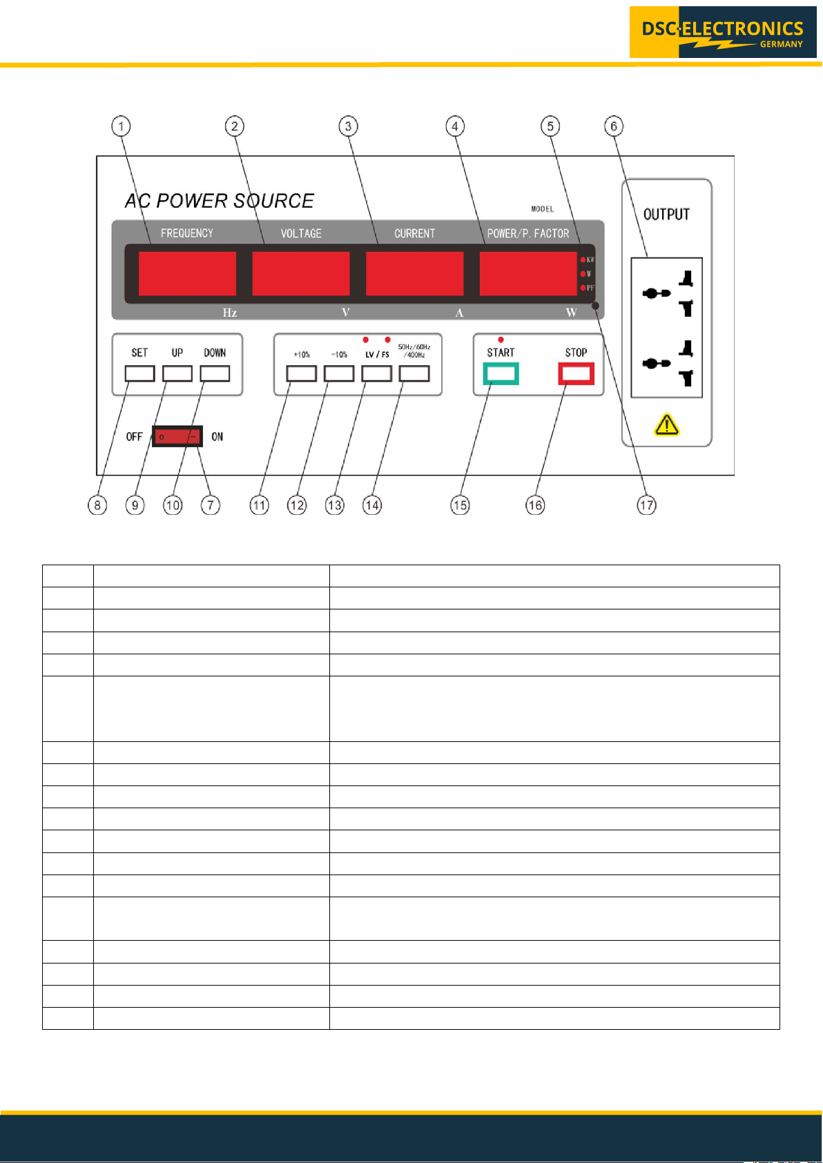
No.
Name
Description
1
Frequency
Output frequency „Hz“
2
Voltage
Voltage set or actual value
3
Current
Current actual value
4
Power / Power Factor
Power or Power Factor display
5
Display Mode
Active „A“ LED indicates the current value
Active „kW“ LED indicates the power value
No active LED indicates the power factor value
6
Connections
Secondary connections with universal socket
7
Power On/Off Key
Power On/Off the power supply
8
Setup Key
Output value setup
9
UP Key
Higher value
10
DOWN Key
Lower value
11
+10% Hot-Key
Higher value by 10 percent
12
-10% Hot-Key
Lower value by 10 percent
13
LV / FS Key
Switch between Low Voltage range (0 – 150V) and Full Scale range (0
– 300V)
14
Frequency Key
Fast switch between 50Hz / 60Hz
15
Start Key
Output ON
16
Stop Key
Output OFF
17
Display Mode Switch Key
Toggle between Current, Power of Power Factor display
3.2 Front Panel Description 61XXX Series
Fig.2: Front Panel 61XXX Series (CV Version)
DSC-Electronics Germany • Georgstraße 36 • 53111 Bonn
Page 7

DF-C 63XXX & 61XXX Series User’s Manual
Version 28.04.2019
DSC-Electronics Germany • Georgstraße 36 • 53111 Bonn
3.3 Power ON
Set the „ON / OFF“ switch to the ON position to turn on the device. The device is equipped with a soft-start delay which
slowly charges the capacities in the power supply to limit the high inrush currents. After about 10 seconds, the power
supply will switch into stand-by mode.
3.3.1 Stand-By Mode
The output is switched off in stand-by mode and the device is ready to set the desired output values. The displays
show a voltage of 0V and a current of 0A, which corresponds to the actual values at the output.
Press the SET button once to enter the setup menu.
Press the SET button once
- FREQUENCY display flashes -> Frequency setting
Press the SET button 2x
- VOLTAGE display flashes -> Voltage setting
Press the SET button 3x
- VOLTAGE display flashes -> FLOAT + percentage setting (default 10%)
Press the SET button 4x
- VOLTAGE display flashes -> FLOAT- percentage setting (default -10%)
Press the SET button 5x
- CURRENT display flashes -> Setting of Over Current Protection value
(In the range 0 - max. output current of the power supply / max. 0 - 50A)
Press the SET button 6x
- Save settings, back to stand-by mode
3.3.3 Setup Menu (CV Version) DF-C61XXX
Press the SET button once to enter the setup menu.
Press the SET button once
- FREQUENCY display flashes -> Frequency setting
Press the SET button 2x
- VOLTAGE display flashes -> Voltage setting
Press the SET button 3 x
- CURRENT display flashes -> setting of the Over Current Protection value
(In the range 0 - max. output current d of the power supply / max. 0 - 50A)
Press the SET button 4x
- Save settings, back to stand-by mode
3.3.4 Setting the output values for constant current sources of the DF-C series (CC version)
Constant current sources of the DF-C series which work in CC mode have no setup menu and a simplified Control
panel. If you are in stand-by mode (output OFF), values can be entered directly using the arrow keys, saving is not
necessary.
3.3.5 Voltage Range Setting (LV / FS)
Press the LV / FS key to switch between the voltage ranges, the currently set voltage range is displayed on the
frequency display for 3 seconds with L for LV and F for FS. Normally the range is LV for 0 - 150V and FS for 0 - 300V,
this may differ for custom-made devices.
DSC-Electronics Germany • Georgstraße 36 • 53111 Bonn
Page 8

DF-C 63XXX & 61XXX Series User’s Manual
Version 28.04.2019
DSC-Electronics Germany • Georgstraße 36 • 53111 Bonn
4. Optional: Analogue In- / Outputs
Devices of the DF-C series can optionally be equipped with analogue inputs / outputs for setting and reading the
output parameters. The analogue outputs / inputs are accessible via a labeled terminal block which is located either
on the back, the front or behind the service door (depending on device model). The pin assignment is explained on the
terminal block for a simple and straight forward connection.
4.1 Optional: Ext. Output On/Off Ctrl. & Interlock
Input for controlling the status of the output of the laboratory power supply (on / off), switchable as “Interlock” or
external control. This input is configured as a two pin connection, a „true“ state is triggered by shorting the two pins
and a „false“ state is triggered by removing any connection between the two pins of the input.
This option can be configured as either an interlock input, which disables the output of the power supply if the state is
false, or as an external output status control which enables or disables the output of the power supply depending on
the control signal state (true = on/false = off) if the „Output On/Off“ switch of the power supply is always in the ON
position.
4.2 Optional: Potential-free output / configurable output
The output of DF-C series devices in the basic version has a potential to PE, which follows the usual protection
regulations. All models can also be ordered in the following modifications (please see the „DF-C Series Function and
Wiring Diagram“ PDF for details):
1). Configurable output without ELCB
The output of the power supply has no potential to the input (PE), so the output of the device has no protective earth
for loads that may require a PE connection and the load is not protected by a ELCB ! By bridging output N to input N,
the output can be pulled to the input potential, in this case input PE = output PE and the load is protected by the ELCB
installed in the operation environment (Laboratory).
2). Configurable output with built-in ELCB
The model with integrated ELCB offers the following switchable configurations:
A). Potential-free output with its own ELCB
Connections output
L (1, 2, 3): Phase (potential-free)
N: Neutral conductor (potential-free)
GND: In this configuration to use as PE connection for the load
Remark: ELCB triggers as soon as a residual current flows through the GND conductor.
Connections input
L1: Input phase 1
L2: Input phase 2
L3: Input phase 3
N: Neutral conductor
PE: Earth conductor
DSC-Electronics Germany • Georgstraße 36 • 53111 Bonn
Page 9

DF-C 63XXX & 61XXX Series User’s Manual
Version 28.04.2019
DSC-Electronics Germany • Georgstraße 36 • 53111 Bonn
B). Output with potential to input (potential to input PE)
Connections output
L (1, 2, 3): Phase
N: Neutral → Bridge to input N
GND: Do not connect
Connections input
L1: Input phase 1
L2: Input phase 2
L3: Input phase 3
N: Neutral conductor
PE: Earth conductor
5. Connection of the load
Depending on the model the output / input connections are located on the back, on the front or behind the service
door of the device. We recommend protecting the connectors from wear if the load will be frequently connected and
disconnected by connecting it not directly to the device, but to use an intermediate bridge. In this case, the
intermediate bridge can remain connected to the power supply - so the connection terminal of the power supply is
used less often.
DSC-Electronics Germany • Georgstraße 36 • 53111 Bonn
Page 10
DF-C 63XXX & 61XXX Series User’s Manual
Version 28.04.2019
DSC-Electronics Germany • Georgstraße 36 • 53111 Bonn
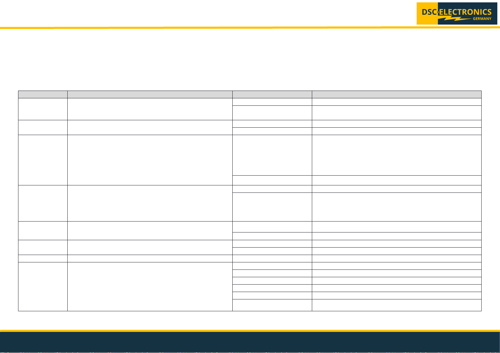
Command
Function
Response
Description
#G
Output START
Received
The command is accepted
Error
The power supply is not in standby mode or output may be
already active
#U
Output STOP
Received
The command is accepted
Error
The power supply output is not active
#D
Read the output status
XXX.XHz;A:XXX.XV
XXX.XAXX.XXkW; B:XXX.XV
XXX.XAXX.XXkW;
C:XXX.XV
XXX.XAXX.XXkW
The reply is a sequence of output frequency, voltage, current
and power. For example:
060.0Hz;A:090.0V010.0A00.90kW;B:090.0V010.0A00.90kW;C:
090.0V010.0A00.90kW.
Error
The power supply output is not active
#SXXXX
XXXX
(S followed by
8 data digits.)
Set the output parameter. The first 4 digits are the
frequency value (resolution 0.1Hz). The last 4 digits are the
voltage setting (resolution 0.1V). The number “0” cannot be
omitted in the command. For example setting the
parameters 101Hz 62V would result in: #S10100620
Received
The command is accepted
Error
The power supply is not in standby mode, or the parameter
exceeds range
#H
Switch to FS (0 – 300V) mode
Received
The command is accepted
Error
Wrong command
#L
Switch to LV (0 – 150V) mode
Received
The command is accepted
Error
Wrong command
#R
STOP output and CLEAR alarm
Received
The command is accepted
#C
Read the status of the power supply
000
Standby mode
001
Started
002
Setup mode
005
Short circuit alarm
006
Over temperature alarm
007
Over current alarm
Communication Protocol for DF-C63XXX Series Power Supplies
Interface: RS-232 (9 pin female) / RS-485 (2 pin male)
Command format: Asynchronous, 1start bit, 8 data bits, 1 stop bit
Baud rate: 9600
Communication mode: ASIIC code, “X” stands for numbers.
Termination: Each command sent by the power supply as reply is terminated with a “;”
DSC-Electronics Germany • Georgstraße 36 • 53111 Bonn
Page 11
DF-C 63XXX & 61XXX Series User’s Manual
Version 28.04.2019
DSC-Electronics Germany • Georgstraße 36 • 53111 Bonn
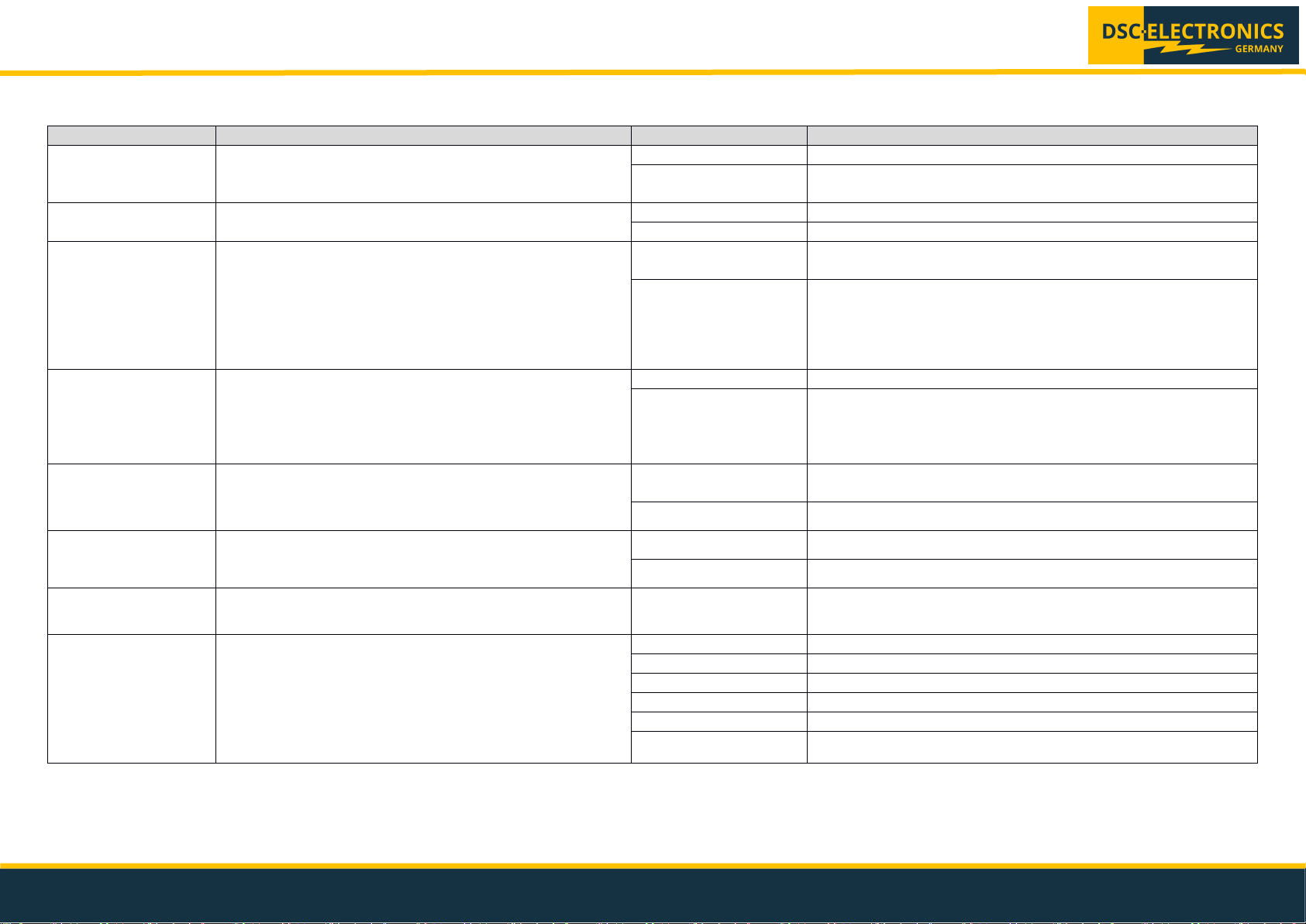
Command
Function
Response
Description
#G
Output START
Received
The command is accepted
Error
The power supply is not in standby mode or output may be
already active
#U
Output STOP
Received
The command is accepted
Error
The power supply output is not active
#D
Read the output status
XXX.XHzXXX.XV
X.XXXAXXXX.XW
The reply is a sequence of output frequency, voltage, current
and power. For example: 050.0Hz110.2V0.950A0099.5W
Error
The power supply output is not active
#SXXXX
XXXX
(S followed by 8
data digits.)
Set the output parameter. The first 4 digits are the
frequency value (resolution 0.1Hz). The last 4 digits are
the voltage setting (resolution 0.1V). The number “0”
cannot be omitted in the command. For example setting
the parameters 101Hz 62V: #S10100620
Received
The command is accepted
Error
The power supply is not in standby mode, or the setting
parameter exceeds range
#H
Switching to FS (0 – 300V) mode
Received
The command is accepted
Error
Wrong command
#L
Switching to LV (0 – 150V) mode
Received
The command is accepted
Error
Wrong command
#R
STOP output and CLEAR alarm
Received
The command is accepted
#C
Read the status of the power supply
000
Standby mode
001
Started
002
Setting mode
005
Short circuit alarm
006
Over temperature alarm
007
Over current alarm
Communication Protocol for DF-C61XXX Series Power Supplies
DSC-Electronics Germany • Georgstraße 36 • 53111 Bonn
 Loading...