

DSC WT5500, WT5500 v1.3 Installaion Instructions
WT5500 v1.3 Installation Instructions
English, Français, Nederlands, Deutsch
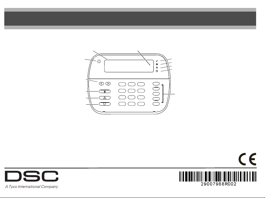
< > indicates user can
LCD
scroll through options
Ambient Light
Sensor
Scroll Keys
Emergency Keys
Fire
Auxiliary
Panic
System is
Ready to Arm
23
1
4
5
89
7
0
*
<>
6
#
WARNING: Please refer to the System Installation Manual for information on limitations regarding product use and function, and information on the limitations as to liability of the manufacturer.
These instructions are to be used in conjunction with the appropriate Control Panel Installation Manual, with which this equipment is intended to be used.
This Installation Sheet applies to the following models: WT5500-433 / WT5500-868 / WT5500P-433 / WT5500P-868.
Operating Instructions shall be made available to the user.
Do not dispose of expended batteries as unsorted municipal waste. Consult your local rules and /or laws regarding the recycling of batteries. Some of the materials that are found within the battery could
become toxic if not disposed properly and/or may affect the environment, and indirectly everybody’s health.
The Model WT5500(P)-433 Wireless Keypad has been certified by Telefication according to EN50131-1:2006 + A1:2009, EN50131-3:2009, for Grade 2, Class II.
LED Indicators
Ready
Armed
Trouble
AC Power
Function
Keys
DG009033
Installation Instructions
The WT5500 Wireless Keypad is compatible with the PC9155 and
SCW9055/SCW9057 Wireless Panels.
Specifications
• Temperature range: -10°C to +55°C (14°F to 131°F)
• Humidity (MAX): 93%R.H.
• Plastic enclosure protection degree: IP30, IK04
• Power adaptor output voltage: 4.5V
• Models - US/Latin America: SA103A-0506-6U; Canada: SA103A-0506-6;
EU: SA103A-0506G-6; UK: SA106C-05BS; AUS./NZ: SA106C-05AS;
China: SA106C-05HS
• Battery: 4 AA, 1.5 V, Energizer Alkaline
• Low Battery Indication: 2.2 V
• WT5500 current draw: 50mA
• Wall-mount tamper
• 5 programmable function keys
• Ready (Green LED), Armed (Red LED), Trouble (Yellow LED), AC (Green LED)
• Frequency: 433.92MHz (WT5500-433/WT5500P-433 only)
• Frequency: 868.35MHz (WT5500-868/WT5500P-868 only)
NOTE: DSC recommends that the keypad be powered by the AC adaptor
and the batteries for EN installations
NOTE: When the power adapter is used, batteries provide minimum
24h back-up.
Unpacking
The WT5500 keypad package is available in five distinct configurations: Wall
Mount, Wall Mount w/Proximity, Desk Stand, Accessory Kit and Proximity
Tags only. The contents of each are described below
Keypad contains patented technology for the Proximity Tag.
WT5500 - WALL MOUNT WT5500DMK - ACCESSORY KIT
• 1 WT5500 Keypad • 1 WT5500DMK Keypad
• 1 WT5500BRK Wall Bracket • 1 Hardware Pack
• 1 Installation Manual • 1 Power Adaptor
• 1 Inner Door Sticker
• 4 AA Batteries
• 1 Hardware Pack • 1 WT5500BRK Wall Bracket
WT5500D - DESK STAND • 1 Installation Manual
• 1 WT5500 Keypad • 1 Inner Door Sticker
• 1 WT5500DMK Desk Stand • 4 AA Batteries
• 1 WT5500BRK Wall Bracket • 1 Hardware Pack
• 1 Installation Manual
• 1 Inner Door Sticker
• 1 Power Adaptor PROXIMITY TAGS ONLY
• 4 AA Batteries
• 2 Hardware Packs • 1 Installation Manual
DC @ 0.5A
.
WT5500P - WALL MOUNT/PROX TAG
• 1 WT5500P Keypad
• 1 PT4 or PT8 Prox Tag (433MHz/868MHz)
• 1 PT4 or PT8 Prox Tag (433MHz/868MHz)
Mounting
You should mount the keypad where it is accessible from designated points
of entry and exit. Once you have selected a dry and secure location, perform
the following steps to mount the keypad.
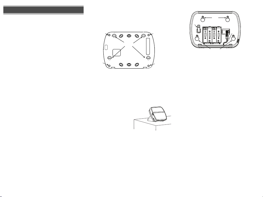
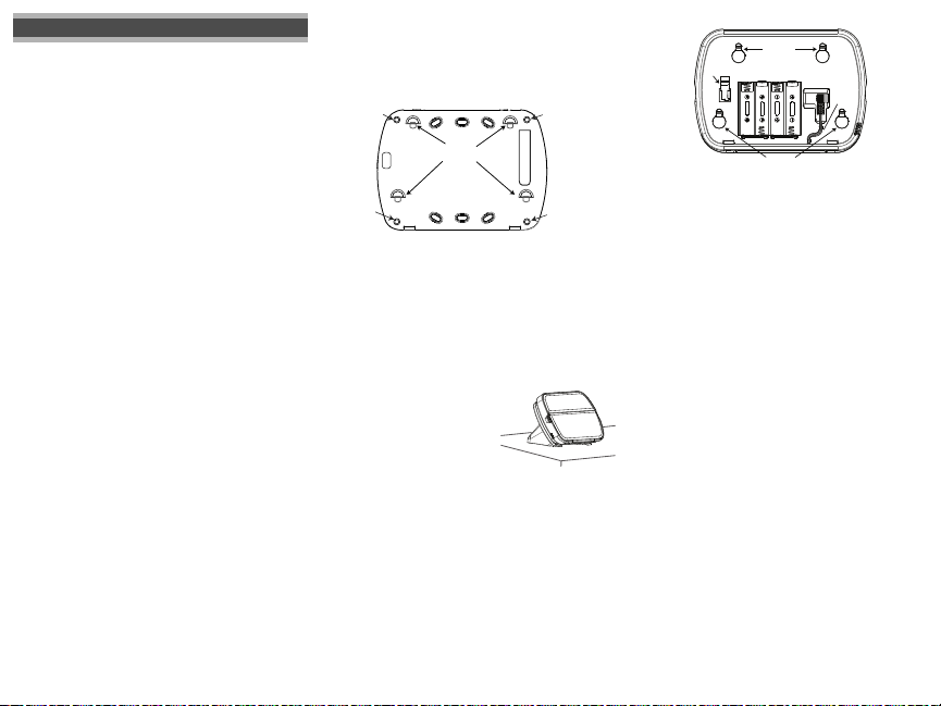
Wall Mounting Plate
1. Locate the screw holes (4) at each corner of the mounting plate.
Screw
Holes
Mounting
Tabs
DG009049
Screw
Holes
2. Use the four screws provided to affix the mounting plate to the wall;
ensure the mounting tabs are facing you (see above diagram).
3. Align the four mounting slots in the WT5500 housing with the four
mounting tabs protruding from the mounting plate.
4. Slide the keypad into place.
5. Firmly but carefully snap the keypad down onto the mounting plate.
6. To fasten the keypad securely onto the mounting plate, locate the two
screw holes in the bottom of the mounting plate then, using the two
screws provided in the hardware pack, screw the keypad into place.
Desk Stand - WT5500D
1. Insert the four rubber feet
(found in the hardware pack)
into the indentations provided
in the bottom of the desk stand.
2. Place the desk stand on a
secure, uncluttered surface.
3. Align the four mounting slots in the WT5500 housing with the four
mounting tabs protruding from the desk stand.
4. Slide the keypad into place. Firmly but carefully snap the keypad down
onto the desk stand.
5. To fasten the keypad securely onto the desk stand, locate the two holes
in the top corners of the back of the desk stand. Using the two screws
provided, screw the keypad to the desk stand.
DG009096
Screw
Holes
Screw
Holes
Apply Battery Power
1. Slide the keypad up and out from the mounting plate/desk stand
(removing the screws first if required). The battery compartment is
open and visible at the back of the keypad.
2. Insert the batteries as directed on the back of the keypad. Ensure the
correct polarity is observed.
3. Replace the keypad on the mounting plate / desk stand.
CAUTION: Do not mix old batteries with new ones.
Mounting
$$
Batteries
$$
Mounting
Holes
Holes
Plug
Wire
Channel
$$
$$
DG009048
Tamper
Switch
Apply AC Power
1. Slide the keypad up and out from the mounting plate / desk stand.
2. Locate the power adaptor jack at the back of the keypad housing.
3. Place the adaptor plug in the housing indentation, perpendicular to the
keypad. Insert the adaptor plug firmly into the jack.
4. Pivot the adaptor plug downwards so that it fits flush with the housing.
Guide the AC wire along the channel provided in the keypad housing;
the wire will extend through the bottom of the housing.
5. Replace the keypad on the mounting plate/desk stand (in the latter case, a
further channel is provided in the bottom of the desk stand. Guide the AC
wire along this channel; the wire will extend through an opening in the
back of the stand).
6. Plug the adaptor into a wall outlet.
NOTE: Only use the power adaptor (4.5VDC, 0.5A, 2.25W) supplied
with the kit.
CAUTION: The socket-outlet in which the direct plug-in adaptor is
inserted, must be close to the keypad and easily accessible. The plug of
the adaptor serves as a means of disconnection from the supply mains.
Programming the Keypad
There are several programming options available for the keypad (see
below). Programming the keypad is similar to programming the rest of the
system. To turn an option on/off, press the number corresponding to the
option on the number pad. The numbers of the options that are currently
turned on will be displayed along the top of the LCD. For information on
programming the rest of your security system, please refer to your system’s Installation Manual.
Language Programming
1. Hold the
[<][>]
2. Scroll to the desired language and press [] to select.
3. To reset custom labels to the selected language, enter [][8][Installer
Code][].
4. Enter [996][].
NOTE: If Section 075, Option 4 is turned off, language programming
can only be performed while in Installer’s programming.
keys for 2 seconds to enter Language Programming.
Enrolling the Keypad
The WT5500 must be configured in tandem with your panel in order for the
system to function as desired.
1. Apply power to the control panel. Keypad enrollment is active during the
first two minutes of system power up. Note that the panel’s Ready and
AC LEDs will be flashing for this two-minute period.
2. A WT5500 must be turned on during this two-minute period for it to be
assigned to the panel.
3. Simultaneously press and hold [
keypad to broadcast its ESN (Electronic Serial Number).
4. When the keypad has been successfully enrolled - this should take less
than 5 seconds - on the system, the message ‘Enrollment Successful’
will be displayed on the keypad LCD for five seconds. The Ready and AC
LEDs will return to their previous state.
5. Repeat steps 3 & 4 on each additional keypad to be enrolled (PC9155 only).
NOTE: Only one WT5500 can be enrolled with the SCW9055/9057.
Programming Labels
1. Use this section to assign a meaningful name (e.g., Front Door, Hallway, etc.) to each zone.
2. Enter keypad programming by pressing
3. Enter the 3-digit section number for the label to be programmed.
4. Use the arrow keys (<>) to move the cursor underneath the letter to
be changed.
5. Press number key 1 through 9, corresponding to the letter you require.
For example, pressing number key 2 once will display the letter D;
pressing it again will display the letter E; pressing it a third time will
display the letter F, and so on.
[1] - A, B, C, 1 [3] - G, H, I, 3 [5] - M, N, O, 5 [7] - S, T, U, 7 [9] - Y, Z, 9,0
[2] - D, E, F, 2 [4] - J, K, L, 4 [6] - P, Q, R, 6 [8] - V, W, X, 8 [0] - Space
6. When the required letter or number is displayed, use the arrow keys
(<>) to scroll to the next letter.
7. When you are finished programming the Zone Label, press [
to ‘Save’ and press [
8. Repeat Steps 3 through 7 until all Labels are programmed.
] and [1]; by doing so you force the
[][8][Installer Code][].
] again.
]. Scroll
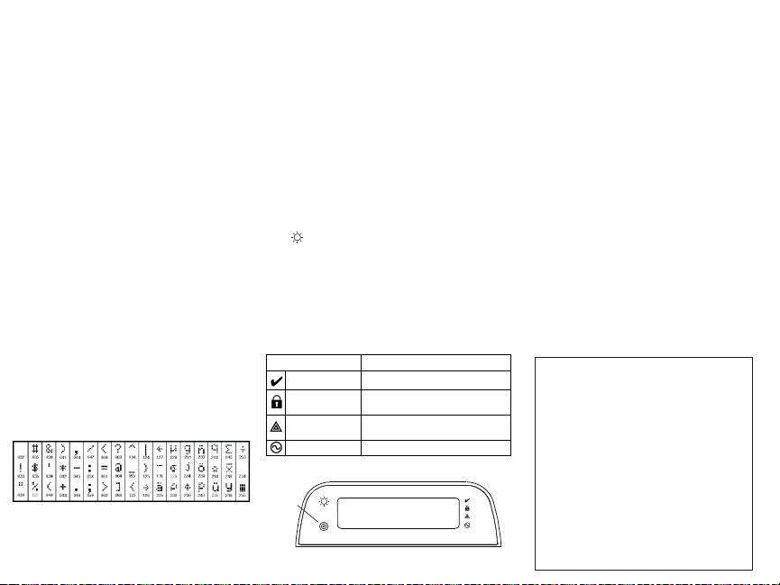
ASCII Characters
Broadcasting LCD Labels
LCD programming is done using Keypad 1 or, if using the SCW9055/
SCW9057, from the main control panel. Labels are broadcast to all other
WT5500 keypads enrolled on the system. Perform the following in order to
broadcast labels:
1. Program Keypad 1 or the SCW9055/9057 control panel completely.
2. Enter keypad programming by pressing [
keypad that was programmed.
3. Enter Section [998] and press []. The label information is then broadcast.
NOTE: This operation may take several minutes.
4. When the label broadcast is complete press the [#] key to exit.
NOTE: Label broadcast from Keypad 1 is only compatible with other
WT5500 keypads (PC9155 only).
][8][Installer Code][] at the
Changing Brightness/Contrast
1. Press [][6] [Master Code].
2. Use the arrow keys (<>) to scroll to Brightness or Contrast Control.
3. Press [
] to select the setting you want to adjust.
4. Brightness Control: There are multiple backlight levels. Use the arrow
keys (<>) to scroll to the desired level. Press [] to select.
5. Contrast Control: There are four different display contrast levels. Use the arrow
keys (<>) to scroll to the desired contrast level. Press [
6. To exit, press [#].
NOTE: During battery operation, the keypad uses the ambient light
sensor to automatically adjust the backlighting brightness levels in
order to conserve battery life.
] to select.
Changing the Buzzer Level
1. Press [][6] [Master Code].
2. Use the arrow keys (<>) to scroll to Buzzer Control. Press [] to select.
3. Use the arrow keys (<>) to scroll to the desired buzzer level among
the 21 available selections.
4. To exit, press [#].
Keypad LED Symbols
Symbol Description
Ready Light (green) If Ready light is ON, the system is ready to arm.
Armed Light (red)
System Trouble (yellow)
AC (green) ON -Indicates that AC is present at the keypad.
If Armed light is ON / Flashing, the system has
been armed successfully.
ON -Indicates that a system trouble is active.
Flashing - Keypad low battery.
Proximity Tags (WT5500P only)
Prox Tag
Reader
DG009153
System is
Ready to Arm
<>
You can use the proximity tag to perform any keypad function that would normally require a user access code. Simply present the tag to the target icon or
to the left of the keypad LCD.
Enrolling Proximity Tags
Enrolling a tag on one keypad will enroll it automatically to all WT5500P
keypads enrolled on the system.
][5][Master Code]. You will enter the User Code Edit Select
1. Enter [
menu.
2. Enter a two-digit User Code slot (01-16, 40) to be associated with the
proximity tag. Alternatively, scroll to the two-digit user number and
press the [
] key. You will enter the New Code Edit menu.
3. Enter the four- or six-digit New Code. The LCD will prompt you to swipe
your proximity tag. Otherwise, press the [#] key to exit.
4. Present your proximity tag to the keypad. If enrollment is successful,
acknowledgement beeps will sound and the keypad LCD will read ‘Tag
Enrolled Successfully’. If the proximity tag has been enrolled previously,
an error tone will sound. The LCD will read ‘Duplicate Tag/User Code’.
5. The keypad will return to the User Code Edit Select menu.
Deleting Proximity Tags
Delete the prox tags from the system when they are lost or no longer needed.
1. Enter [][5] [Master Code] on the keypad.
2. The keypad will display the user number and include the letter ‘T’ if a
prox tag is programmed.
3. Enter or select the User Code slot you wish to delete.
4. Press [
] to delete both the user code and the proximity tag.
NOTE: User codes can only be deleted individually.
NOTE: User 40 - Master Code cannot be deleted; a deletion attempt on
this user code will delete the proximity tag only.
NOTE: A user code, once deleted, must be re-enrolled before it can be
used again.
+HUHE\ '6& GHFODUHV WKDW WKLV GHYLFH LV LQ FRPSOLDQFH ZLWK WKH HVVHQWLDO
UHTXLUHPHQWVDQGRWKHUUHOHYDQWSURYLVLRQVRI'LUHFWLYH(&
7KH FRPSOHWH 577( 'HFODUDWLRQ RI &RQIRUPLW\ FDQ EH IRXQG DW
KWWSZZZGVFFRPOLVWLQJVBLQGH[DVS[
&=( '6& MDNR Y¿UREFH SURKODģXMH ŀH WHQWR Y¿UREHN MH Y VRXODGX VH YģHPL
UHOHYDQWQ¯PLSRŀDGDYN\VPÝUQLFH(&
'$1'6&HUNO¨UHUKHUYHGDWGHQQHNRPSRQHQWHQRYHUKROGHUDOOHYLNWLJHNUDYVDPW
DQGUHEHVWHPPHOVHUJLWWLGLUHNWLY(&
'87+LHUELM YHUNODDUW'6&GDW GLWWRHVWHOLQ RYHUHHQVWHPPLQJLV PHWGHHLVHQ HQ
EHSDOLQJHQYDQULFKWOLMQ(&
),1'6&YDNXXWWDDODLWWHHQW¦\WW¦Y¦QGLUHNWLLYLQ(&ROHQQDLVHWYDDWLPXNVHW
)5(3DU ODSU«VHQWH '6&G«FODUHTXH FHGLVSRVLWLI HVWFRQIRUPHDX[ H[LJHQFHV
HVVHQWLHOOHVHWDXWUHVVWLSXODWLRQVSHUWLQHQWHVGHOD'LUHFWLYH(&
*(5+LHUGXUFKHUNO¦UW'6&GD¡GLHVHV*HU¦WGHQHUIRUGHUOLFKHQ%HGLQJXQJHQXQG
9RUUDXVHW]XQJHQGHU5LFKWOLQLH(&HQWVSULFKW
*5(˂˜˞˱ˬ˲ ˭˞ˮ˹˪˱ˬ˯ˤ'6&ˡˤ˨˻˪ˢ˦ ˹˱˦˞˲˱˛ˤ˰˲˰˧ˢ˲˛ ˢ˜˪˞˦˰˺˩˳˶˪ˤ˩ˢ˱˦˯
ˬ˲˰˦˻ˡˤ˯˞˭˞˦˱˛˰ˢ˦˯˧˞˦˩ˢ˹˨ˢ˯˱˦˯˙˨˨ˢ˯˰˴ˢ˱˦˧˚˯˞˪˞˳ˬˮ˚˯˱ˤ˯ˍˡˤˠ˜˞˯(&
,7$ &RQOD SUHVHQWHOD 'LJLWDO 6HFXULW\&RQWUROV GLFKLDUD FKHTXHVWR SURGRWWR ª
FRQIRUPH DLUHTXLVLWL HVVHQ]LDOL HGDOWUH GLVSRVL]LRQL ULOHYDQWLUHODWLYH DOOD 'LUHWWLYD
&(
125'6&HUNO¨UHUDWGHQQHHQKHWHQ HULVDPVYDUPHGGHJUXQQOHJJHQGHNUDY RJ
ºYULJHUHOHYDQWHNUDYLGLUHNWLY()
32/'6&RĝZLDGF]DľHXU]ÇG]HQLHMHVWZ]JRGQRĝFL]]DVDGQLF]\PLZ\PDJDQLDPL
RUD]SR]RVWDĄ\PLVWRVRZQ\PLSRVWDQRZLHQLDPL'\UHNW\Z\:(
3253RUHVWHPHLR D'6&GHFODUDTXHHVWH HTXLSDPHQWRHVW£HPFRQIRUPLGDGH
FRP RV UHTXLVLWRV HVVHQFLDLV H RXWUDV GHWHUPLQD©·HV UHOHYDQWHV GD 'LUHFWLYD
(&
63$3RU ODSUHVHQWH'6&GHFODUD TXHHVWHHTXLSR HVW£HQFRQIRUPLGDG FRQORV
UHTXLVLWRVHVHQFLDOHV\RWURVUHTXLVLWRVUHOHYDQWHVGHOD'LUHFWLYD(&
6:('6&EHNU¦IWDU K¦UPHGDWWGHQQD DSSDUDWXSSI\OOHUGHY¦VHQWOLJD NUDYHQRFK
DQGUDUHOHYDQWDEHVW¦PPHOVHUL'LUHNWLYHW(&

Limited Warranty
Digital Security Controls (DSC) warrants that for a period of 12 months from the date
of purchase, the product shall be free of defects in materials and workmanship under
normal use and that in fulfilment of any breach of such warranty, DSC shall, at its
option, repair or replace the defective equipment upon return of the equipment to its
repair depot. This warranty applies only to defects in parts and workmanship and not
to damage incurred in shipping or handling, or damage due to causes beyond the
control of DSC such as lightning, excessive voltage, mechanical shock, water damage, or damage arising out of abuse, alteration or improper application of the equipment. The foregoing warranty shall apply only to the original buyer, and is and shall
be in lieu of any and all other warranties, whether expressed or implied and of all
other obligations or liabilities on the part of DSC. DSC neither assumes responsibility for, nor authorizes any other person purporting to act on its behalf to modify or to
change this warranty, nor to assume for it any other warranty or liability concerning
this product. In no event shall DSC be liable for any direct, indirect or consequential
damages, loss of anticipated profits, loss of time or any other losses incurred by the
buyer in connection with the purchase, installation or operation or failure of this
product. WARNING: DSC recommends that the entire system be completely tested
on a regular basis. However, despite frequent testing, and due to, but not limited to,
criminal tampering or electrical disruption, it is possible for this product to fail to perform as expected. Important Information: Changes or modifications not expressly
approved by DSC could void the user’s authority to operate this equipment.
EN50131-1 Grade 2, Class 2, EN50131-6 Type B
Important Information
could void the user’s authority to operate this equipment.
IMPORTANT - READ CAREFULLY: DSC Software purchased with or without
Products and Components is copyrighted and is purchased under the following
license terms:
• This End-User License Agreement (“EULA”) is a legal agreement between
(the company, individual or entity who acquired the Software and any related Hardware) and
Ltd.
oper of the software and any related products or components (“HARDWARE”)
which You acquired.
• If the DSC software product (“SOFTWARE PRODUCT” or “SOFTWARE”) is
intended to be accompanied by HARDWARE, and is NOT accompanied by new
HARDWARE, You may not use, copy or install the SOFTWARE PRODUCT. The
SOFTWARE PRODUCT includes computer software, and may include associated
media, printed materials, and “online” or electronic documentation.
• Any software provided along with the SOFTWARE PRODUCT that is associated
with a separate end-user license agreement is licensed to You under the terms of
that license agreement.
• By installing, copying, downloading, storing, accessing or otherwise using the
SOFTWARE PRODUCT, You agree unconditionally to be bound by the terms of this
EULA, even if this EULA is deemed to be a modification of any previous arrangement or contract. If You do not agree to the terms of this EULA, DSC is unwilling to
license the SOFTWARE PRODUCT to You, and You have no right to use it.
SOFTWARE PRODUCT LICENSE
The SOFTWARE PRODUCT is protected by copyright laws and international
copyright treaties, as well as other intellectual property laws and treaties. The
SOFTWARE PRODUCT is licensed, not sold.
1. GRANT OF LICENSE This EULA grants You the following rights:
(a) Software Installation and Use - For each license You acquire, You may have only
one copy of the SOFTWARE PRODUCT installed.
(b) Storage/Network Use - The SOFTWARE PRODUCT may not be installed, accessed,
displayed, run, shared or used concurrently on or from different computers, including a
workstation, terminal or other digital electronic device (“Device”). In other words, if You
have several workstations, You will have to acquire a license for each workstation where the
SOFTWARE will be used.
(c) Backup Copy - You may make back-up copies of the SOFTWARE PRODUCT, but
You may only have one copy per license installed at any given time. You may use the
back-up copy solely for archival purposes. Except as expressly provided in this EULA, You
: Changes/modifications not expressly approved by DSC
Digital Security Controls, a division of Tyco Safety Products Canada
(“DSC”), the manufacturer of the integrated security systems and the devel-
You
may not otherwise make copies of the SOFTWARE PRODUCT, including the printed
materials accompanying the SOFTWARE.
2. DESCRIPTION OF OTHER RIGHTS AND LIMITATIONS
(a) Limitations on Reverse Engineering, Decompilation and Disassembly - You
may not reverse engineer, decompile, or disassemble the SOFTWARE PRODUCT, except
and only to the extent that such activity is expressly permitted by applicable law
notwithstanding this limitation. You may not make any changes or modifications to the
Software, without the written permission of an officer of DSC. You may not remove any
proprietary notices, marks or labels from the Software Product. You shall institute
reasonable measures to ensure compliance with the terms and conditions of this EULA.
(b)
Separation of Components
single product. Its component parts may not be separated for use on more than
one HARDWARE unit.
(c)
Single INTEGRATED PRODUCT
HARDWARE, then the SOFTWARE PRODUCT is licensed with the HARDWARE as a
single integrated product. In this case, the SOFTWARE PRODUCT may only be
used with the HARDWARE as set forth in this EULA.
(d)
Rental
- You may not rent, lease or lend the SOFTWARE PRODUCT. You may
not make it available to others or post it on a server or web site.
(e)
Software Product Transfer
EULA only as part of a permanent sale or transfer of the HARDWARE, provided You
retain no copies, You transfer all of the SOFTWARE PRODUCT (including all
component parts, the media and printed materials, any upgrades and this EULA),
and provided the recipient agrees to the terms of this EULA. If the SOFTWARE
PRODUCT is an upgrade, any transfer must also include all prior versions of the
SOFTWARE PRODUCT.
(f)
Termination
EULA if You fail to comply with the terms and conditions of this EULA. In such
event, You must destroy all copies of the SOFTWARE PRODUCT and all of its
component parts.
(g)
Trademarks
any trademarks or service marks of DSC or its suppliers.
3. COPYRIGHT
- All title and intellectual property rights in and to the SOFTWARE
PRODUCT (including but not limited to any images, photographs, and text
incorporated into the SOFTWARE PRODUCT), the accompanying printed materials,
and any copies of the SOFTWARE PRODUCT, are owned by DSC or its suppliers.
You may not copy the printed materials accompanying the SOFTWARE PRODUCT.
All title and intellectual property rights in and to the content which may be
accessed through use of the SOFTWARE PRODUCT are the property of the
respective content owner and may be protected by applicable copyright or other
intellectual property laws and treaties. This EULA grants You no rights to use such
content. All rights not expressly granted under this EULA are reserved by DSC and
its suppliers.
4. EXPORT RESTRICTIONS
SOFTWARE PRODUCT to any country, person, or entity subject to Canadian export
restrictions.
5. CHOICE OF LAW
the Province of Ontario, Canada.
6. ARBITRATION
determined by final and binding arbitration in accordance with the Arbitration Act, and
the parties agree to be bound by the arbitrator’s decision. The place of arbitration
shall be Toronto, Canada, and the language of the arbitration shall be English.
7. LIMITED WARRANTY
(a) NO WARRANTY
WARRANTY. DSC DOES NOT WARRANT THAT THE SOFTWARE WILL MEET YOUR
REQUIREMENTS OR THAT OPERATION OF THE SOFTWARE WILL BE
UNINTERRUPTED OR ERROR-FREE.
(b) CHANGES IN OPERATING ENVIRONMENT -
problems caused by changes in the operating characteristics of the HARDWARE,
or for problems in the interaction of the SOFTWARE PRODUCT with non-DSCSOFTWARE or HARDWARE PRODUCTS.
(c) LIMITATION OF LIABILITY; WARRANTY REFLECTS ALLOCATION OF RISK - IN
ANY EVENT, IF ANY STATUTE IMPLIES WARRANTIES OR CONDITIONS NOT STATED IN THIS
- The SOFTWARE PRODUCT is licensed as a
- If You acquired this SOFTWARE with
- You may transfer all of Your rights under this
- Without prejudice to any other rights, DSC may terminate this
- This EULA does not grant You any rights in connection with
- You agree that You will not export or re-export the
- This Software License Agreement is governed by the laws of
- All disputes arising in connection with this Agreement shall be
- DSC PROVIDES THE SOFTWARE “AS IS” WITHOUT
DSC shall not be responsible for
LICENSE AGREEMENT, DSC’S ENTIRE LIABILITY UNDER ANY PROVISION OF THIS LICENSE
AGREEMENT SHALL BE LIMITED TO THE GREATER OF THE AMOUNT ACTUALLY PAID BY
YOU TO LICENSE THE SOFTWARE PRODUCT AND FIVE CANADIAN DOLLARS (CAD$5.00).
BECAUSE SOME JURISDICTIONS DO NOT ALLOW THE EXCLUSION OR LIMITATION OF
LIABILITY FOR CONSEQUENTIAL OR INCIDENTAL DAMAGES, THE ABOVE LIMITATION MAY
NOT APPLY TO YOU.
(d) DISCLAIMER OF WARRANTIES - THIS WARRANTY CONTAINS THE ENTIRE
WARRANTY AND SHALL BE IN LIEU OF ANY AND ALL OTHER WARRANTIES, WHETHER
EXPRESSED OR IMPLIED (INCLUDING ALL IMPLIED WARRANTIES OF MERCHANTABILITY
OR FITNESS FOR A PARTICULAR PURPOSE) AND OF ALL OTHER OBLIGATIONS OR
LIABILITIES ON THE PART OF DSC. DSC MAKES NO OTHER WARRANTIES. DSC NEITHER
ASSUMES NOR AUTHORIZES ANY OTHER PERSON PURPORTING TO ACT ON ITS BEHALF
TO MODIFY OR TO CHANGE THIS WARRANTY, NOR TO ASSUME FOR IT ANY OTHER
WARRANTY OR LIABILITY CONCERNING THIS SOFTWARE PRODUCT.
(e) EXCLUSIVE REMEDY AND LIMITATION OF WARRANTY - UNDER NO
CIRCUMSTANCES SHALL DSC BE LIABLE FOR ANY SPECIAL, INCIDENTAL,
CONSEQUENTIAL OR INDIRECT DAMAGES BASED UPON BREACH OF WARRANTY,
BREACH OF CONTRACT, NEGLIGENCE, STRICT LIABILITY, OR ANY OTHER LEGAL THEORY.
SUCH DAMAGES INCLUDE, BUT ARE NOT LIMITED TO, LOSS OF PROFITS, LOSS OF THE
SOFTWARE PRODUCT OR ANY ASSOCIATED EQUIPMENT, COST OF CAPITAL, COST OF
SUBSTITUTE OR REPLACEMENT EQUIPMENT, FACILITIES OR SERVICES, DOWN TIME,
PURCHASERS TIME, THE CLAIMS OF THIRD PARTIES, INCLUDING CUSTOMERS, AND
INJURY TO PROPERTY.
completely tested on a regular basis. However, despite frequent testing,
and due to, but not limited to, criminal tampering or electrical disruption, it
is possible for this SOFTWARE PRODUCT to fail to perform as expected.
FCC Compliance Statement
Caution: Changes or modifications not expressly approved by Digital Security Controls
could void your authority to use this equipment.
This equipment generates and uses radio frequency energy and if not installed and
used properly, in strict accordance with the manufacturer’s instructions, may cause
interference to radio and television reception. It has been type tested and found to
comply with the limits for Class B device in accordance with the specifications in
Subpart “B” of Part 15 of FCC Rules, which are designed to provide reasonable
protection against such interference in any residential installation. However, there is no
guarantee that interference will not occur in a particular installation. If this equipment
does cause interference to television or radio reception, which can be determined by
turning the equipment off and on, the user is encouraged to try to correct the
interference by one or more of the following measures: (i) Re-orient the receiving
antenna; (ii) increase the separation between the equipment and receiver; (iii) connect
the equipment into an outlet on a circuit different from that to which the receiver is
connected. If necessary, the user should consult the dealer or an experienced radio/
television technician for additional suggestions. The user may find the following
booklet prepared by the FCC helpful: “How to Identify and Resolve Radio/Television
Interference Problems”. This booklet is available from the U.S. Government Printing
Office, Washington, D.C. 20402, Stock # 004-000-00345-4.
This Class B digital apparatus complies with Canadian ICES-003.
Cet appareil numérique de la classe B est conforme à la norme NMB-003 du Canada.
IC:160A-WT5500: The term IC before the radio certification number signifies that the
Industry Canada technical specifications were met.
The trademarks, logos, and service marks displayed on this document are registered in
the United States [or other countries]. Any misuse of the trademarks is strictly
prohibited and Tyco International Ltd. will aggressively enforce its intellectual property
rights to the fullest extent of the law, including pursuit of criminal prosecution wherever
necessary. All trademarks not owned by Tyco International Ltd. are the property of their
respective owners, and are used with permission or allowed under applicable laws.
Product offerings and specifications are subject to change without notice. Actual
products may vary from photos. Not all products include all features. Availability varies
by region; contact your sales representative.
WARNING: DSC recommends that the entire system be
©2011 Tyco International Ltd. and its Respective Companies. All Rights Reserved • www.dsc.com • Tech. Support: 1-800-387-3630 (Canada, US), 905-760-3000 • Printed in Canada

Keypad Function Key Programming
Enter keypad programming by pressing [][8][Installer Code][][000]. Press 1 through 5 for individual
function key programming.
[1]-[5] Function Key Assignment
Function Key Button
[1] Function Key 1 00 - 33 03 Stay Arm I_______I_______I
[2] Function Key 2 00 - 33 04 Away Arm I_______I_______I
[3] Function Key 3 00 - 33 06 Chime On/Off I_______I_______I
[4] Function Key 4 00 - 33 08 Bypass I_______I_______I
[5] Function Key 5 00 - 33 16 Quick Exit I_______I_______I
Keypad Function Keys
Please see your system installation manual for more details on the function key options below.
[00] - Null [06] - Chime On/Off [15] - For Future Use
[01] - For Future Use [07] - For Future Use [16] - Quick Exit
[02] - For Future Use [08] - Bypass Mode [17] - Activate Stay/Away Zones
[03] - Stay Arm [09] - [12] - For Future Use [25] - Instant Stay Arm
[04] - Away Arm [13] - Command Output 1 [33] - Night Arm
[05] - No Entry Arm [14] - Command Output 2
Keypad Programming
Enter keypad programming by pressing [][8][Installer Code][]
[001]-[034] Zone Label 1 to 34
E.g., For Zone 1 enter section 001, for Zone 2 enter section 002, etc.
Section Zone Label
[001] to [034] 1-34
[065] Fire Alarm Label
Default: ’Fire_Zone’
I_____I_____I_____I_____I_____I_____I_____I_____I_____I_____I_____I_____I_____I_____I
[065]
I_____I_____I_____I_____I_____I_____I_____I_____I_____I_____I_____I_____I_____I_____I
Valid
Default Function
Range
(Default: ‘Zone _01’ - ‘Zone _34’)
I_____I_____I_____I_____I_____I_____I_____I_____I_____I_____I_____I_____I_____I_____I
I_____I_____I_____I_____I_____I_____I_____I_____I_____I_____I_____I_____I_____I_____I
[066] Fail to Arm Event Message
Default: ‘System_Has_Failed_to_Arm’
I_____I_____I_____I_____I_____I_____I_____I_____I_____I_____I_____I_____I_____I_____I
[066]
I_____I_____I_____I_____I_____I_____I_____I_____I_____I_____I_____I_____I_____I_____I
[067] Alarm When Armed Event Message
Default: ‘Alarm_Occurred_While_Armed_ < >’
I_____I_____I_____I_____I_____I_____I_____I_____I_____I_____I_____I_____I_____I_____I
[067]
I_____I_____I_____I_____I_____I_____I_____I_____I_____I_____I_____I_____I_____I_____I
[074] First Keypad Options
Default Opt. ON OFF
ON I_____I 1 Fire Key Enabled Fire Key Disabled
ON I_____I 2 Auxiliary Key Enabled Auxiliary Key Disabled
ON I_____I 3 Panic Key Enabled Panic Key Disabled
ON I_____I 4 Quick Arm Prompt ON Quick Arm Prompt OFF
OFF I_____I 5 Quick Exit Prompt ON Quick Exit Prompt OFF
ON I_____I 6 Bypass Options Prompt ON Bypass Options Prompt OFF
ON I_____I 7 User Initiated Call-up Prompt ON User Initiated Call-up Prompt OFF
ON I_____I 8 Hold Key [P] Prompt ON Hold Key [P] Prompt OFF

[075] Second Keypad Options
Default Opt. ON OFF
ON I_____I 1 Local Clock Display ON Local Clock Display OFF
OFF I_____I 2 Local Clock Displays 24-hr Time Local Clock Displays AM/PM
ON I_____I 3 Auto Alarm Scroll ON Auto Alarm Scroll OFF
ON I_____I 4
OFF I_____I 5 Power LED Enabled Power LED Disabled
ON I_____I 6 Power LED Indicates AC Present ON Power LED Indicates AC Present OFF
ON I_____I 7 Alarms Displayed While Armed Alarms Not Displayed While Armed
OFF I_____I 8 Auto-Scroll Open Zones ON Auto-Scroll Open Zones OFF
Language Selection Available From Any
Menu
Language Selection Available in
Installer’s Only
[076] Third Keypad Options
Default Opt ON OFF
OFF OFF
I____I 1 Armed LED On in Sleep Mode Armed LED Off in Sleep Mode
ON I____I 2 Keypad Status Shows Stay Arm Keypad Status Shows Stay/Away Arm
OFF ON
I____I 3
ON I____I 4 Ambient Light Sensor ON Ambient Light Sensor OFF
ON I____I 5 Late to Open Prompts Late to Open Prompts
ON I____I 6 Power Save Mode ON Power Save Mode OFF
OFF I____I 7 For Future Use For Future Use
OFF ON
I____I 8 Local RF Jam Detect Enabled Local RF Jam Detect Disabled
NOTE: Programming options indicated in GREY are required for systems compliant with EN50131-1
and EN50131-3 standards. Section [076]: 1=OFF, 3=ON, 8=ON.
Trouble Acknowledgement
Prompt Enabled
Trouble Acknowledgement Prompt
Disabled
[077] LCD Message
I_____I_____I_____I_____I_____I_____I_____I_____I_____I_____I_____I_____I_____I_____I_____I_____|
[077]
I_____I_____I_____I_____I_____I_____I_____I_____I_____I_____I_____I_____I_____I_____I_____I_____|
[078] Download LCD Message Duration
Default: 003 I_____I_____I_____I (Valid entries are 000-255), 000=Unlimited Message Display
This number represents the number of times the downloaded message is cleared by pressing any key
after the message has timed out.
[100] CO Detector Alarm Label
Default: ‘CO_Alarm_Evacuate_Area’
Section/Label
I_____I_____I_____I_____I_____I_____I_____I_____I_____I_____I_____I_____I_____I______|______|_____|
[100]
I_____I_____I_____I_____I_____I_____I_____I_____I_____I_____I_____I_____I_____I______|______|_____|
[101] System Label
Default: ‘System’
Section/Label
I_____I_____I_____I_____I_____I_____I_____I_____I_____I_____I_____I_____I_____I_____|______|_____|
[101]
I_____I_____I_____I_____I_____I_____I_____I_____I_____I_____I_____I_____I_____I_____|______|_____|
[120] Partition 1 Command Output #1
Default: ‘Command_O/P_1’
Section/Label
I_____I_____I_____I_____I_____I_____I_____I_____I_____I_____I_____I_____I_____I_____|______|_____|
[120]
I_____I_____I_____I_____I_____I_____I_____I_____I_____I_____I_____I_____I_____I_____|______|_____|
[121] Partition 1 Command Output #2
Default: ‘Command_O/P_2’
Section/Label
I_____I_____I_____I_____I_____I_____I_____I_____I_____I_____I_____I_____I_____I_____|______|_____|
[121]
I_____I_____I_____I_____I_____I_____I_____I_____I_____I_____I_____I_____I_____I_____|______|_____|
[996] Reset Programmable Labels to Factory Defaults
[997] View Software Version
[998] Global Label Broadcast
[999] Reset Keypad Programming to Factory Defaults

NOTES

NOTES
Instructions d’installation du WT5500 v1.3
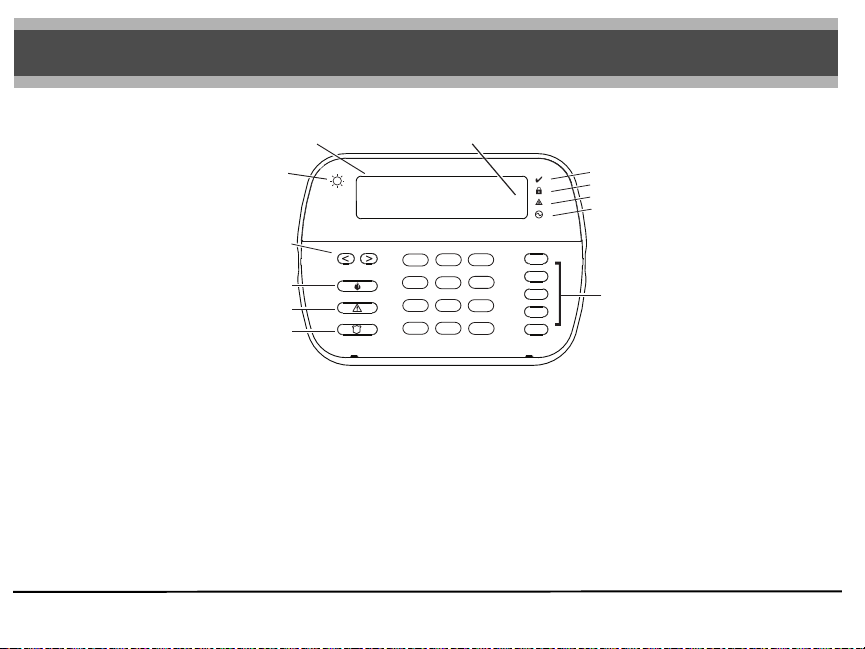
< > indique que l’utilisateur peut
LCD
faire défiler les options
Capteur lumière
ambiante
Système prêt
à armer
Touches de
défilement
Touches d’urgence
Feu
Auxiliaire
Panique
MISE EN GARDE : Ce manuel contient des renseignements sur les limites de l’utilisation et du fonctionnement de ce produit ainsi que des renseignements sur les limites relatives à la responsabilité du fabricant. Ces instructions doivent être utilisées avec le Manuel d’installation de la centrale de contrôle approprié pour lequel ce dispositif a été conçu.
Cette notice d’installation s’applique aux modèles suivants : WT5500-433 / WT5500-868 / WT5500P-433 / WT5500P-868.
Le mode d’emploi doit être donné à l’utilisateur.
Ne jetez pas les piles usée dans les déchets municipaux non triés. Consultez les règlements et/ou lois de votre région concernant le recyclage des piles. Certains matériels qui se trouvent dans la pile pour-
raient devenir toxiques s’ils ne sont pas éliminés correctement et/ou ils pourraient affecter l’environnement, et indirectement la santé de tous.
Les claviers modèles WT5500(P)-433 ont été homologués par Telefication conformément à EN50131-1:2006 + A1:2009, EN50131-3:2009 pour Grade 2, Classe II.
1
4
7
*
23
6
5
8
9
0
#
Voyants
Prêt
MES (Armé)
Trouble
Alimenté CA
Touches
de fonction
Instructions d’installation
Le clavier WT5500 a été conçu pour fonctionner avec la centrale sans-fil PC9155
et SCW9055/SCW9057.
Caractéristiques
• Plage de température : De -10 °C à + 55 °C (14 °F à 131 °F)
• Humidité (MAX) : 93 % H.R.
• Degré de protection du coffret en plastique : IP30, IK04
• Tension de sortie de l’adaptateur de courant : 4,5 VCC @ 0,5 A
• Modèles - É.-U./ SA103A-0506-6U ; Canada : SA103A-0506-6 ; UE :
SA103A-0506G-6 ; R.-U. : SA106C-05BS ; AUS./NZ : SA106C-05AS.
• Pile : 4 piles alcalines Energizer AA, 1.5 V
• Indication pile faible: 2.2V
• Appel de courant du WT5500 : 50 mA
• Autoprotection murale
• 5 touches papramétrables
• Prêt (voyant vert), MES (rouge), Trouble (jaune), CA (vert)
• Fréquence : 433,92 MHz (WT5500-433/WT5500P-433 seulement)
• Fréquence : 868.35MHz (WT5500-868/WT5500P-868 seulement)
REMARQUE: DSC recommande que le clavier soit alimenté par l'adaptateur CA et les piles pour les installations EN.
REMARQUE: Lorsqu'un adaptateur de courant est utilisé, les piles
assurent le secours pendant au moins 24h.
Déballage
L’ensemble du clavier WT5500 est offert en cinq configurations distinctes, installation murale, installation murale avec détection de proximité, socle, ensemble
d’accessoires et tags de proximité seulement. Le contenu de chaque configuration
est décrit ci-dessous.
WT5500-INSTALLATION MURALE WT5500DMK - ENSEMBLE D’ACCESSOIRES
• 1 clavier WT5500 • 1 clavier WT5500DMK
• 1 support mural WT5500BRK • 1 sachet de quincaillerie
• 1 Manuel d’installation • 1 Adaptateur de courant
1 autocollant pour l’intérieur de la
•
porte
• 4 piles AA • 1 clavier WT5500P
• 1 Paquet de quincaillerie • 1 support mural WT5500BRK
WT5500D - SOCLE • 1 Manuel d’installation
• 1 Clavier WT5500 • 1 autocollant pour l’intérieur de la porte
• 1 Socle WT5500DMK • 4 piles AA
• 1 Support mural WT5500BRK • 1 Matériel
• 1 Manuel d’installation
• 1 autocollant pour l’intérieur de
la porte TAGS DE PROXIMITÉ SEULEMENT
• 1 Adaptateur de courant
• 4 piles AA • 1 Manuel d’installation
• 2 paquets de quincaillerie
WT5500P - INSTALLATION MURALE/TAG DE
PROXIMITÉ
• 1 tag de proximité PT4/PT8 (433/868MHz)
• 1 tag de proximité PT4/PT8 (433/868 MHz)
Installation
Il convient d’installer le clavier à un endroit accessible aux points d’entrée et de
sortie désignés. Une fois que vous avez sélectionné un endroit sec et sûr, effectuez
les étapes suivantes pour installer le clavier.
Plaque de montage murale
1. Trouvez les trous de vis (4) à chaque coin de la plaque de montage.
Trous de
vis
Languettes de
montage
DG009229
Trous de
vis
2. Utilisez les quatre vis fournies pour fixer la plaque de montage au mur,
vérifiez que les languettes de montage vous font face (voir diagramme cidessus).
3. Alignez les quatre fentes de montage du boîtier du WT5500 avec les quatre
languettes de montage ressortant de la plaque de montage.
4. Faites glisser le clavier à sa place.
5. Fermement, mais soigneusement, enclenchez le clavier sur la plaque de
montage.
6. Pour fixer le clavier de manière plus sûre sur la plaque de montage, trouvez
les deux trous de vis au bas de la plaque de montage puis, à l’aide des
deux vis fournies dans le paquet de quincaillerie, vissez le clavier en place.
Socle - WT5500D
1. Insérez les quatre pieds en caoutchouc
(qui se trouvent dans le paquet de quincaillerie) dans les indentations sous le
socle.
2. Placez le socle sur une surface sécuritaire
et nette.
3. Alignez les quatre fentes de montage du boîtier du WT5500 avec les quatre
languettes de montage ressortant du socle.
4. Faites glisser le clavier à sa place. Fermement, mais soigneusement,
enclenchez le clavier sur le socle.
5. Pour fixer le clavier de manière plus sûre sur le socle, trouvez les 2 trous de
vis aux coins supérieurs à l’arrière du socle puis, à l’aide des deux vis fournies dans le paquet de quincaillerie, vissez le clavier au socle.
Mise sous tension de la pile
1. Faites glisser le clavier vers le haut et enlevez-le de la plaque de montage
ou du socle (enlevez d’abord les vis si nécessaire). La porte pour les quatre
piles AA est ouverte et visible à l’arrière du clavier.
2. Insérez les piles conformément aux instructions au dos du clavier. Vérifiez
que la polarité est respectée.
3. Replacez le clavier sur la plaque de montage/socle.
Trous de
vis
Trous de
vis
Attention – Ne pas mélanger de nouvelles batteries avec les vieilles.
Trous de
montage
Interrupteur
Sabotage
Piles
Prise
$$
$$
DG009230
Mise sous tension CA
1. Faites glisser le clavier vers le haut et enlevez-le de la plaque de montage
ou du socle.
2. Trouvez la prise de l’adaptateur de courant au dos du boîtier du clavier.
3. Placez la fiche de l’adaptateur dans l’indentation du boîtier, perpendiculairement au clavier. Insérez la fiche de l’adaptateur fermement dans la prise.
4. Faites pivoter la fiche de l’adaptateur vers le bas de sorte qu’il soit encastré
dans le boîtier. Passez le fil CA le long du guide-fil se trouvant sur le boîtier
du clavier ; le fil passera enfin au fond du boîtier.
5. Replacez le clavier sur la plaque de montage/le socle (dans ce dernier cas,
un autre guide-fil se trouve sous le socle). Guidez le fil CA le long de ce
chemin de câbles ; le fil passera dans une ouverture au dos du socle).
6. Branchez l’adaptateur dans une prise de courant murale.
REMARQUE: Utilisez uniquement l’adaptateur de courant (4,5 V.c.c.,
0,5 A, 2,25 W) fourni dans la trousse.
REMARQUE: La prise de courant dans laquelle l’adaptateur à enfichage direct est inséré doit être près du clavier et facilement accessible.
La fiche de l’adaptateur sert de moyen de déconnexion du câble d’alimentation principale.
Paramétrage du Clavier
P
lusieurs options de paramértage sont offertes pour le clavier (voir ci-dessous).
Le paramétrage du clavier est similaire au paramétrage du reste du système.
Pour activer ou désactiver une option, saisissez le chiffre correspondant à
l’option sur le clavier numérique. Les chiffres des options actuellement activées
seront affichés en haut de l’écran LCD. Pour des renseignements sur la manière
de paramétrer le reste de votre système de sécurité, veuillez consulter le manuel
d’installation de votre système.
Sélection de la langue
1. Maintenez les touches (<>) pendant 2 secondes pour saisir le paramé-
trage de la langue.
2. Faites défiler jusqu’à la langue désirée et saisissez [] pour sélectionner.
3. Pour rétablir les étiquettes programmable à la langue sélectionnée,
appuyant [][8][Code Installateur][].
4. Appuyez [996][].
REMARQUE: Si la Section 075, Option 4 est désactivée, la sélection de
la langue ne peut se faire que dans le mode Installateur.
Trous de
montage
Guide-fil
$$
$$
 Loading...