

DSC WS900-19UL, WS900-29UL, WS901-24EU, WS901-34EU, WS901-18 Reference Manual
...
Wireless Security and Automation System
V1.0 Reference Manual
WARNING: This manual contains information on limitations regarding product use and function and information on the
limitations as to liability of the manufacturer. The entire manual should be carefully read.
Models:
WS900UL/WS901

Table of Contents
Section 1: Introduction 2
1.1 About the System 2
1.1.1 Available Models 2
1.2 Compatible Devices List 2
1.3 Specifications 5
Section 2: Installation 7
2.1 Alarm Controller Installation 7
Figure 2-1 Panel Connections 8
Figure 2-2 Panel Bottom 8
Figure 2-3 Battery Compartment 8
Figure 2-4 Battery Removal 8
2.2 Controls and Indicators 9
Figure 2-5 LED Indicators 9
2.3 Enrolling Wireless PowerG Security Devices 12
Section 3: Operation 13
3.1 Using the Integrated Keypad 13
Figure 3-1 Keypad - Normal Operating Mode 13
Figure 3-2 Keypad - Shift Mode 13
3.1.1 Key Functions 13
3.1.2 Emergency Keys 13
3.1.3 WPS Mode ([*]8) 14
3.2 Arming and Disarming Methods 14
3.2.1 Away Arming 14
3.2.2 Stay Arming 14
3.2.3 Quick Arming 15
3.2.4 Disarming 15
Section 4: Programming Options 16
4.1 Integrated Keypad Options 16
4.2 System Configuration Options 16
4.2.1 Reporting Configuration Options 21
4.2.2 Network Configuration Options 22
4.3 Central Monitoring Station Programming Options 23
4.3.1 Other Communicator Related Options 26
4.4 2-Way Voice Options 28
4.5 Partition Configuration Options 28
4.6 Wireless Device Configuration Options 30
4.6.1 Wirefree Keypad Configuration Options 30
4.6.2 User Configuration Options 31
4.6.3 Wireless Siren Configuration Options 32
4.6.4 Wireless Key Configuration Options 33
4.6.5 Wireless Smoke and CO Configuration Options 33
4.6.6 Wireless Glassbreak Configuration Options 34
- 2 -

4.6.7 Wireless Temperature Configuration Options 35
4.6.8 Wireless Flood Configurations 36
4.6.9 Wireless PIR CAM Configurations 37
4.6.10 Wireless PIR (NO CAM) Configurations 38
4.6.11 Wireless Door Window Configurations 39
4.6.12 Wireless Shock Sensor Configurations 40
4.6.13 Repeater Configuration Options 41
4.7 Available Zone Types 42
4.8 Available Zone Attributes 43
4.9 Diagnostics - Read Only 43
4.10 System Control 43
4.10.1 Device 44
4.10.2 Network 44
Section 5: Troubleshooting 45
5.1 Testing: 45
5.2 Viewing Troubles from the Integrated Keypad 45
5.3 Network Troubleshooting 47
Appendix 1: Guidelines for Locating Smoke Detectors and CO Detectors 48
Appendix 2: Reporting Codes 51
Appendix 3: Regulatory Information 57
Appendix 3: EULA 62
Appendix 4: Limited Warranty 63
Appendix 5: WARNING: Installer please read carefully 64
- 3 -

iotega Wireless Security and Automation System
Safety Instructions for Service Persons
Warning: When using equipment connected t o the telephone network, always follow
the basic safety instructions provided with this product. Save these instructions for
future reference. Inform the end-user of the safety precautions t hat must be observed
when operating t his equipment.
Before Installing The Equipment
Ensure your package includes the following items:
l Installation and User manuals, includingthe SAFETY INSTRUCTIONS.
READ and SAVE these instructions!
Follow all WARNINGS AND INSTRUCTIONS specified within this doc-
ument and/or on t he equipment.
l iotega alarm controller
l Power Supply, direct plug-in
l Ethernet cable
Selecting A Suitable Location For The Alarm Controller
Use the following list as a guide t o find a suitable location to install t his equipment:
l Locate near a power outlet.
l Select a location free from vibration and shock.
l Place alarm controller on aflat, stable surface and follow the inst allation
instructions.
Do NOT locate t his product where people may walk on the secondary circuit cable(s).
Do NOT connect alarm controller t o electrical the same circuit as largeappliances.
Do NOT select a location that exposes your alarm controller to direct sunlight, excess-
ive heat, moisture, vapors, chemicals or dust.
Do NOT inst all t his equipment near water. (e.g., bath tub, kitc hen/laundry sink, wet
basement, neara swimming pool).
Do NOT inst all t his equipment and accessories in areas whererisk of explosion
exists.
Do NOT connect this equipment to electrical outlets controlled by wall switches or
automatic timers.
AVOID interference sources.
AVOID installing equipment near heaters, air conditioners, ventilators, and
refrigerators.
AVOID locating equipment c lose to or on top of large metal objects (e.g., wall
studs).
See "Locating Detectors and Escape Plan" on page 1 for information onlocating
smoke and CO detectors.
SAFETY Precautions Required During Installation
l NEVER install this equipment during a lightning storm.
l Position c ables so that accidents can not occur. Connected cables must
NOT be subject to excessive mechanical strain.
l Use only the power supply provided with this equipment. Use of unauthorized
power supplies may cause damage.
WARNING: THIS EQUIPMENT HAS NO MAINS ON/OFF SWITCH. THE
PLUG OF THE DIRECT PLUG-IN POWER SUPPLYIS INTENDED TO
SERVE AS THE DISCONNECTING DEVICE IF T HE EQUIPMENT MUST
BE QUICKLY DISCONNECTED. IT IS IMPERATIVE THAT ACCESS TO
THE MAINS PLUG AND ASSOCIATED MAINS SOCKET/OUTLET IS
NEVER OBSTRUCTED.
IMPORTANT NOTE FORNORTHAMERICA!
This alarm system must be installed and used within an environment that
provides the pollution degree max 2 and over-voltages category II NONHAZARDOUS LOCATIONS, indoor only. The equipment is DIRECT
PLUG-IN (external transformer) and is designed to be installed, serviced
and/or repaired by service persons only; [service person is defined as a
person having the appropriate technical training and experience necessary
to be aware of hazards to which that person maybe exposed in performing
a taskand of measures to minimize the risks to that person or other
persons]. Thisequipment has no mains on/off switch; if the equipment must
be quicklydisconnected, the plug of the direct plug-in power supplyis
intended to serve as the disconnecting device; it isimperative that accessto
the mainsplug and associated mainssocket/outlet,is never obstructed.
There are no parts replaceable by the end-user within this equipment. The
wiring (cables) used for installation of the alarm system and accessories,
shallbe insulated with PVC, TFE, PTFE, FEP, Neoprene or Polyamide.
(a) Internal wiring must be routed in amanner that prevents:
- Excessive strain or loosening of wire on terminal connections;
- Damage of conductor insulation
(b) Disposal of used batteries must be made in accordance with local waste
recovery and recycling regulations.
(c) Before servicing, DISCONNECT the power.
(d) DO NOT route anywiring over circuit boards.
(e) The installer isresponsible to ensure that a readily accessible disconnect
device is incorporated in the building for permanently connected
installations.
The power supplymust be ClassII, FAIL SAFE with double or reinforced
insulation between the PRIMARY and SECONDARY
CIRCUIT/ENCLOSURE and be an approved type acceptable to the local
authorities. All national wiring rules must be observed.
IMPORTANT NOTE FORINTERNATIONALMARKET (EU,
AUS, NZ)!
This equipment is stationary-fixed and must be installed byService Persons
only (Service Person isdefined asa person having the appropriate technical
training and experience necessary to be aware of hazards to which that
person may be exposed in performing a task and of measures to minimize
the risks to that person or other persons). It must be installed and used
within an environment that providesthe pollution degree max 2, over
voltagescategory II, in non-hazardous, indoor locationsonly. When using
equipment connected to the mains and/or to the telecommunication
network, there are basic safety instructions that should always be followed.
Refer to the safety instructions provided with thisproduct and save them for
future reference. To reduce the riskof fire, electric shock and/or injury,
observe the following: Do not attempt to service this product yourself.
Opening or removing the cover mayexpose you to dangerous voltage or
other risk. Refer servicing to qualified service persons. Use authorized
accessories only with this equipment. DO NOT leave and/or depositANY
object on the top of the cabinet of this equipment! The cabinet as it is
installed on the wall is not designed to support any supplementary weight!
Do not spill any liquidson the cabinet or equipment. Do not touch the
equipment and its connected cables during an electricalstorm; there may be
a risk of electric shock. Never touchuninsulated wires or terminals unless
the equipment has been disconnected from the mains supply and from the
telecommunication network! Ensure that cables are positioned so that
accidents cannot occur. Connected cables must not be subject to excessive
mechanicalstrain. Do not use the Alarm system to report a gasleak if the
system is near a leak.
These safety instructions should not prevent you from contacting
the distributor and/or the manufacturer to obtain any further cla-
rification and/or answers to your concerns.
- 1 -

Section 1: Introduction
Section 1: Introduction
1.1 About the System
The iotega is an easy to use, wireless security and home automation panel. iotega supports a range of wireless devices via
PowerG or Z-Wave.
Installers set up and configure the panel through a smartphone app or cloud-based portal. End users also interact with the
iotega using an intuitive smartphone app, web portal or optional wirefree and touchscreen keypads.
1.1.1 Available Models
The following alarm controller models are available:
l WS900
l WS901
Note: Not all models are available in all markets. Only WS900 supports two-way audio.
Model Differences
The table below lists the features of each alarm system model.
UL
Model PowerG (MHz) Wi-Fi (GHz)** Z-Wave (MHz)* 2-Way Audio*
WS900-19
WS900-29
WS901-14 433 2.4 No No
WS901-24EU 433 2.4 868.4 No
WS901-34EU 433 2.4 868.4 No
WS901-18 868 2.4 No No
WS901-28 868 2.4 868.4 No
WS901-24AU 433 2.4 921.4 No
WS901-34AU 433 2.4 921.4 No
*Not evaluated by UL
** 802.11b/g/n
Note: Only models withULdesignation are UL/ULC listed.
UL
UL
915 2.4 No Yes
915 2.4 908.4 Yes
1.2 Compatible Devices List
The following table lists all devices compatible with the iotega.
Note: Only models withULare UL/ULC listed. For UL/ULC certified installations use only UL/ULC listed devices.
Note: 'x' refers to detector frequency: 4 = 433MHz, 9 = 868MHz, 9 = 915MHz
Product Type Model
Modules
- 2 -

Section 1: Introduction
Product Type Model
Touchscreen Keypad* WS9TCHW
Wirefree LCD Keypad WS9LCDWF
Cellular Communicator 3G7090/LT7090
PowerG
Wireless vanishing door/window contact PGx975
Wireless door/window contact w/ AUX PGx945
Wireless smoke detector PGx926
Wireless smoke and heat detector PGx916
Wireless CO detector PGx913
UL
UL
UL
UL
UL
PIR/Pet Immune Motion Detector PGx914
Wireless PIR motion detector PGx904(P)
Wireless PIR + camera motion detector PGx934(P)
UL
UL
Wireless Outdoor PG PIR + camera motion detector PGx944
Wireless curtain motion detector PGx924
UL
Wireless dual tech motion detector PGx984(P)
Wireless mirror motion detector PGx974(P)
Wireless outdoor motion detector PGx994
Wireless glass break detector PGx912, PGx922
Wireless shock detector PGx935
Wireless flood detector PGx985
Wireless temperature detector (indoor use) PGx905
Wireless 4-button key PGx939ULPGx929
UL
UL
UL
UL
UL**
UL**
UL
Wireless panic key PGx938
Wireless 2-button key PGx949
Wireless indoor siren PGx901
Wireless outdoor siren PGx911
Wireless repeater PGx920
UL
UL
UL
UL
IP Devices
These supplementary devices have not been evaluated by UL/ULC for compatibility with the alarm control panel.
Camera Wi-Fi IP Camera See the Smarttech portal for available
models
Touchpad Wi-Fi Touchscreen (dedicated as a system
WS9TCHW
keypad)
Phone Cellular Phone w/Wi-Fi iOS/Android based
- 3 -

Section 1: Introduction
Z-Wave Devices
See the Smarttech portal for a complete list of supported Z-Wave devices.
Note: These supplementary devices have not been evaluated by UL/ULC for compatibility with the alarm control panel.
Central Monitoring Station Receivers
Receiver Sur-Gard System I-IP Receiver SG-System I-IP
Receiver Sur-Gard System II Receiver SG-System II
Receiver Sur-Gard System III Receiver SG-System III
Receiver Sur-Gard System IV Receiver SG-System IV
Receiver Sur-Gard System 5 Receiver SG-System 5
* Touchscreen device not evaluated by UL/ULC
**These devices shall not be used in UL/ULC listed installations.
- 4 -

Section 1: Introduction
1.3 Specifications
Zone Configuration
l 128 wireless zones
l 18 zone types and 9 programmable zone attributes
l 4 touchscreen keypads supported (not evaluated by UL/ULC)
l 4 wirefree keypads (not evaluated by UL/ULC)
l 16 wireless sirens
l 8 wireless repeaters
l 32 wireless keys supported
l 8 wireless repeaters supported. Note that more than one wireless repeater shall be installed in a given fire alarm sig-
naling system to provide a redundant RF transmission path.
Access Codes
l Up to 100 access codes, plus one installer code and one duress code
l Programmable attributes and partition assignment for each user code
Warning Device Output
l Integral sounder capable of 85 dB @ 3m
l 2 remote, wireless indoor/outdoor warning devices supported: models PGx901 (indoor), PGx911 (outdoor)
l Programmable as steady, pulsed, temporal three (as per ISO8201) or temporal four (CO alarm)
l Warning device sounds alarms in the following priority: Fire, CO, Burglary
Memory
l 128MB RAM
l 4GB eMMC solid-state drive
l 128MB embedded FLASH memory
Power Supply - North America
Transformer:
Primary: 120VAC, 0.35A, 60Hz Class II
Secondary: 12VDC, 1.16A
Standard Battery
l Model: DSC model 17000178, 7.4V,1.0Ah lithium-Ion, rechargeable (Note: This battery pack shall not be used with
UL/ULC Household Fire Alarm Signaling system)
l Backup time: 4 hours
l Recharging time to 85%: 24 hours (UL)
l Low battery threshold: 7.3V
l Low battery restore: 7.4V
l Battery Critical Shutdown: 6.1V
l Battery lifespan: 3-5 years
Extended Battery
l Model: DSC model 17000179, 7.4V, 4.5Ah, lithium-Ion, rechargeable
l backup time: 24 hours
l Recharging time to 85%: 24 hours (UL)
l Low battery threshold: 7.3V
l Low battery restore: 7.4V
- 5 -

Section 1: Introduction
l Battery Critical Shutdown: 6.2V
l Battery lifespan: 3-5 years
Operating Environmental Conditions
l Temperature range: UL= 0°C to +49°C (32°F-120°F), EN= -10°C to 55°C (50°F-131°F)
l Relative humidity: <93% non condensing
Alarm Transmitter Equipment (ATE) Specification
l Communications over cellular or Ethernet
l Supports SIA and Contact ID
l Complies with TS203 021-1, -2, -3 Telecom equipment requirements and EN50136-1-1, EN50136-2-1, EN50136-2-3
ATS 2
l Compliant with EN50136-1-1, EN50136-2-1 ATS2 requirements
System Supervision Features
The iotega continuously monitors a number of possible trouble conditions and provides audible and visual indication at the
keypad if a trouble is present. Trouble conditions include:
l AC power failure
l Zone trouble
l Fire trouble
l Communicator trouble
l Low battery condition
l RF jam
l Failure to communicate
l Module fault (supervisory or tamper)
Additional Features
l 2-way audio Talk/Listen support*
l Audio verification*
l Quick arming
l User, partition, module, zone and system labels
* Not evaluated by UL.
- 6 -

Section 2: Installation
Section 2: Installation
2.1 Alarm Controller Installation
Installing the iotega consists of connecting and powering up the hardware, as well as configuring the device using the
installer portal.
An typical installation includes the following steps:
1. Install the hardware
2. Create an account for the panel
3. Assign a service plan
4. Add a gateway
5. Create a master contact
6. Enroll sensors and other devices
7. Select Go Live on the Accounts: Summary page to bring the iotega online.
8. Test panel operation
To install the iotega:
1. Locate the panel on a flat surface in close proximity to AC power and a wireless router.
2. Remove the plastic pull tab from the access cover on the back of the panel to activate the battery. If the battery is not
installed, see Installing a new Battery below.
3. Connect the Ethernet cable to the port on the back of the panel. Connect the other end of the cable to the wireless
router.
Note: For EN installations, use only the supplied Ethernet cable.
4. Connect the barrel jack of the plug-in adapter to the power connector on the back of the panel. Route the power
cable through the strain relief channel on the bottom of the panel then plug the adapter into an AC outlet. The iotega
powers up once connected to AC.
The power-up sequence is as follows:
l The integrated keypad numbers illuminate in sequence until the power up sequence is complete.
l After approximately 40 seconds the Power LED illuminates.
l The Ethernet Link Speed LED illuminates steady green and the Ethernet Link Activity LED flashes rapidly to
indicate that a connection is being made to the Tyco cloud.
l After several minutes, depending on network speed, the Remote Connection LED illuminates steady green
(or flashing green if installer access window is enabled), indicating that a connection has been established.
For more information on LED indicators, see on page 9.
Note: If the Remote Connection Status LED flashes red, the panel may be having difficulty connecting to the TycoOn serv-
ers. Restarting the panel may remedy the issue. The following UDP ports must be open: 1234, 1235, and 1236. If the prob-
lem persists, contact DSC technical support.
Note: When replacing the battery, use battery pack suitable for the application. Refer to on page 5.
- 7 -
Section 2: Installation
Push tab
to
release
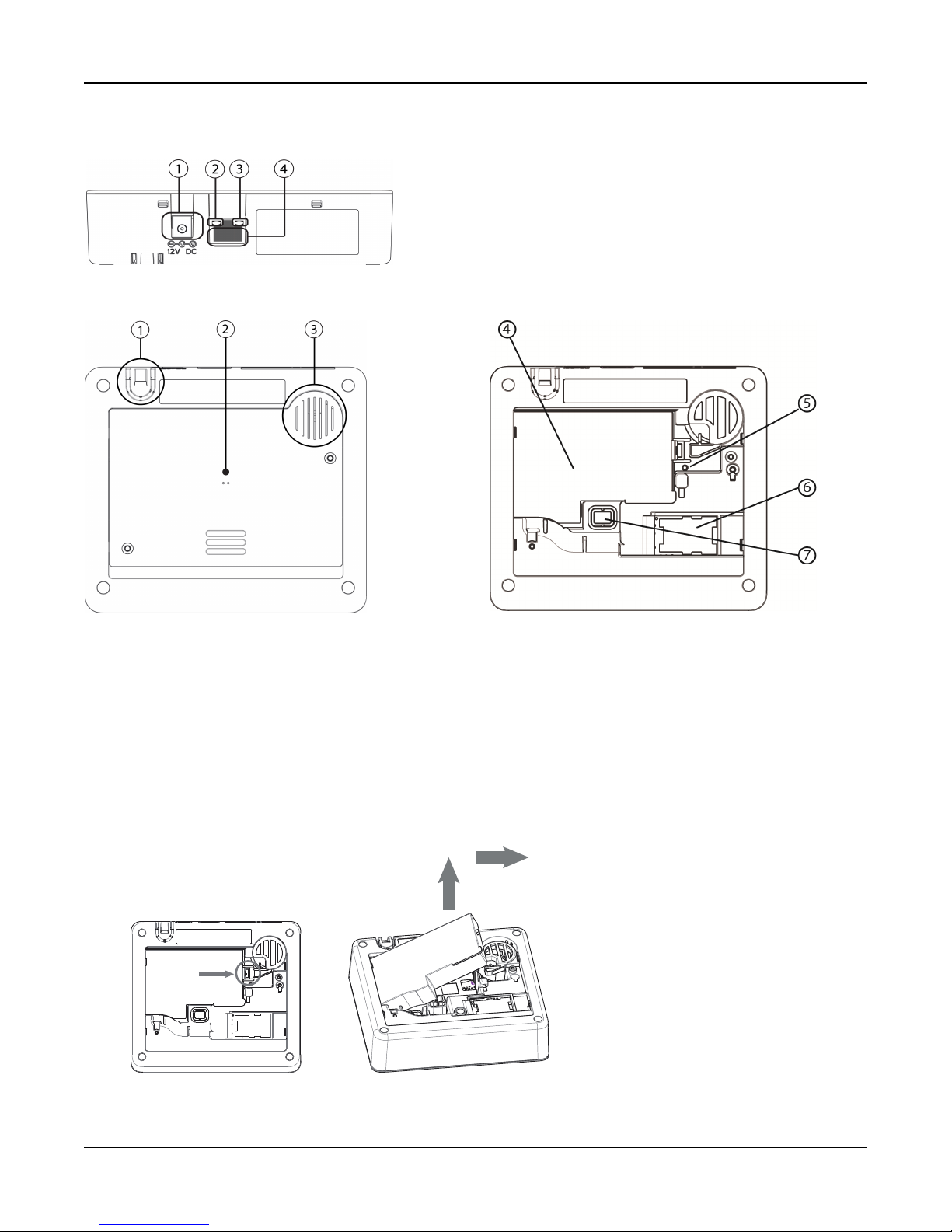
Figure 2-1 Panel Connectio ns
1. Power Connector
2. Ethernet Link Speed LED
3. Ethernet Link Activity LED
4. Ethernet Port
Figure 2-2 Panel Bottom Figure 2-3 Battery Compartment
1. Power cable Strain Relief
2. Access Cover for Battery, SIM Card and Reset Button
3. Speaker
4. Battery
5. Reset button
6. SIM card
7. Tamper switch
Removing the Battery
1. Remove the access cover from the back of the panel.
2. Push the battery retention tab in the direction of the arrow in Figure 2-4 .
3. Lift the battery from the front, then pull up and slide out.
Figure 2-4 Battery Removal
- 8 -
Section 2: Installation
Installing a new battery
1. Remove the access cover from the back of the panel.
2. Insert the battery, back end first, as shown in Figure 2-4 .
3. Press the front of the battery down until the retention tab clicks into place.
4. Replace the back cover of the panel.
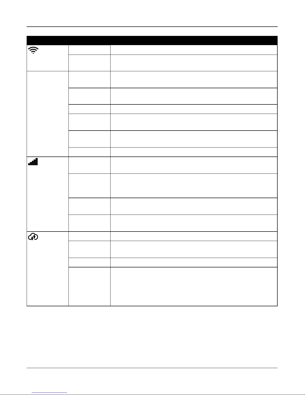
2.2 Controls and Indicators
The iotega provides a series of LED indicators to notify users of system status.
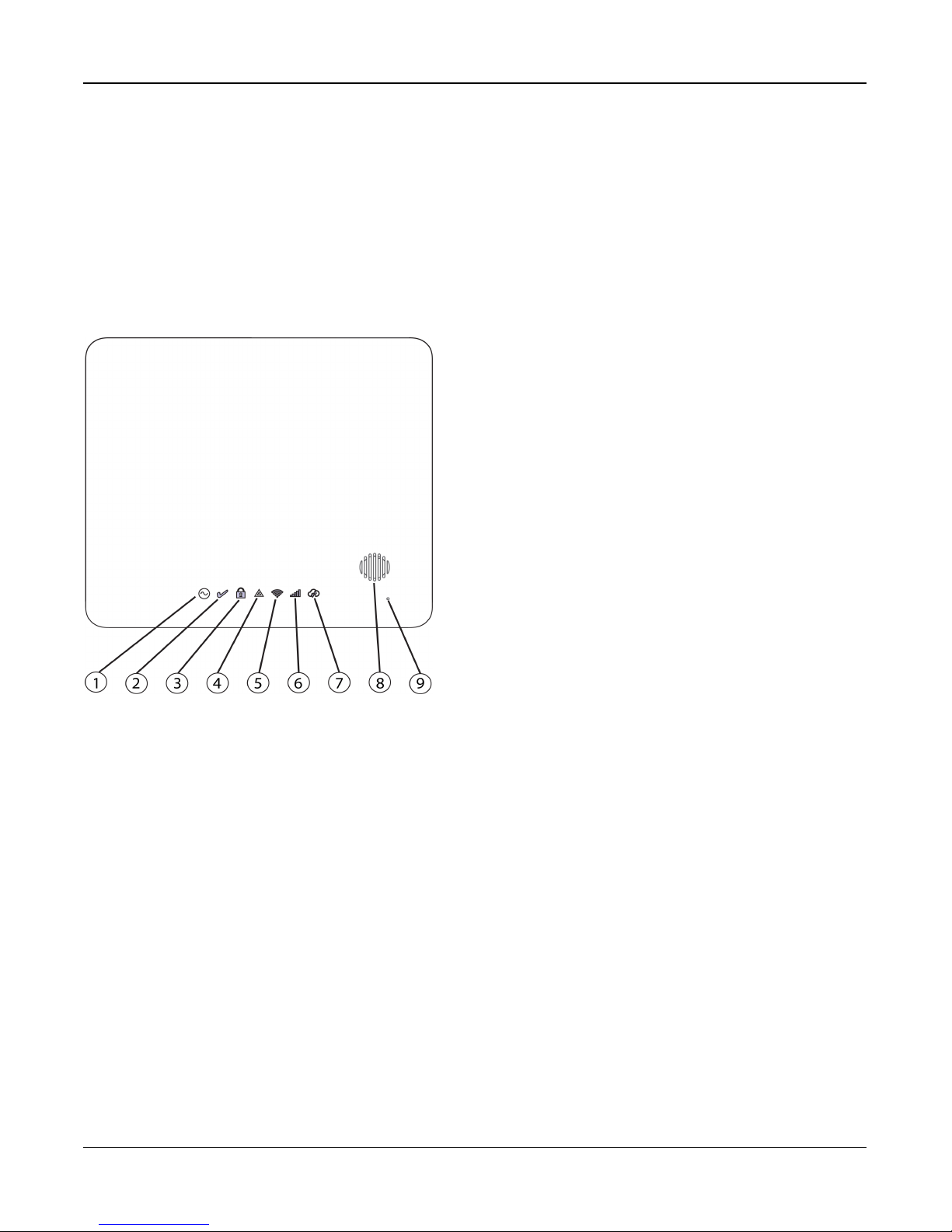
Figure 2-5 LED Indicators
1. Power LED
2. Ready to Arm LED
3. Armed LED
4. Trouble LED
5. WiFi Signal Strength LED
6. Cellular Signal Strength LED
7. Remote Connection LED
8. Siren
9. Microphone
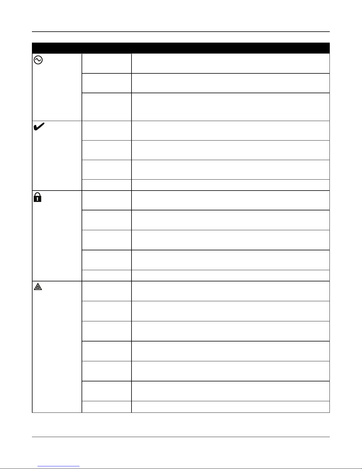
Table 2-1 LED Indicator Operation
- 9 -
Section 2: Installation
LED Indicator Description
Power
Ready
Armed
ON Steady
AC power is currently connected to the system.
[Green]
Flashing [Amber] System Test
(All status LEDs flashing at same time)
OFF · System is not powered On
· NO AC connected, and system operating on backup battery
· NO AC connected and backup battery is discharged.
ON Steady
System is ready to arm.
[Green]
OFF System is not ready to arm. Not all zones are secure or a Fire or CO alarm is
present.
Flashing [Amber] System Test (AC, Ready, Trouble, Arm LED’s, WiFi Trouble, Cellular Trouble &
System remote status flashing at same time)
Flashing [Green] Installer Walk Test (Ready, Trouble and Arm LED’s flashing at same time)
ON Steady
Partition is armed.
[Red]
Flashing
System in Alarm. [Note: this LED does not flash for silent alarms or panic alarms
[Red]
Trouble
Flashing
[Amber]
Flashing
System Test (AC, Ready, Trouble, Arm LED’s, WiFi Trouble, Cellular Trouble &
System remote status flashing at same time)
Installer Walk Test (Ready, Trouble and Arm LED’s flashing at same time)
[Red]
OFF Partition is disarmed or audible alarm annunciation is deactivated.
ON Steady
System trouble is present
[Yellow]
Single flash
[*][2] System Trouble menu is accessed
[Yellow]
Two flashes
System In second level sub-menu
[Yellow]
Three Flashes
System In third level sub-menu
[Yellow]
Flashing
[Amber]
Flashing
System Test (AC, Ready, Trouble, Arm LED’s, WiFi Trouble, Cellular Trouble &
System remote status flashing at same time)
Installer Walk Test (Ready, Trouble and Arm LED’s flashing at same time)
[Yellow ]
OFF No system troubles
- 10 -
Section 2: Installation
LED Indicator Description
Wi-Fi Signal
Strength
Cellular Sig-
nal Strength
ON Steady [Green] Strong Signal Connection
ON Flashing
[Green]
ON Steady
[Yellow]
ON Flashing [Yel-
low]
On Steady [Red] No Signal
Flashing
[Red]
Flashing
[Amber]
OFF WiFi disabled
ON Steady [Green] Strong signal connection
ON Steady
[Yellow]
Wi-Fi active in WSA mode (for AP mode)
Weak Signal Connection
Z-Wave enrollment mode
Hardware Network reset
System Test (AC, Ready, Trouble, Arm LED’s, WiFi Trouble, Cellular Trouble &
System Remote Status flashing at same time)
Weak signal connection
Remote Con-
nection Status
ON Steady
[Red]
Flashing
[Amber]
ON Steady [Green] Link to remote server is active
ON Flash
[Red]
OFF Link to remote server is not active
Flashing
[Amber]
No Signal or no connection
System Test (AC, Ready, Trouble, Arm LED’s, WiFi Trouble, Cellular Trouble &
System remote status flashing at same time)
Link to remote server is active but has failed to communicate
System Test (AC, Ready, Trouble, Arm LED’s, WiFi Trouble, Cellular Trouble &
System Remote Status flashing at same time)
Note: If the Remote Connection status LED flashes red, the panel may be having
difficulty connecting to the remote server. Restarting the panel may remedy the
issue. If the problem persists, contact DSC technical support.
Reset Button
Pressing and holding the Reset button, located under the battery cover (see figure 3-3), for a minimum of 10 seconds per-
forms a vendor reset. WiFi configurations (client mode) are returned to default settings.
Pressing and holding the Reset button for a minimum of 20 seconds returns the following options to their default settings:
SSID, security key, security type and reconnection to DHCP.
Note: The system must be disarmed with no alarms in memory in order for the Reset button to function as described above.
- 11 -

Section 2: Installation
Tamper Switch
The panel includes a tamper switch under the back battery cover. If the battery cover is removed while the system is dis-
armed, the tamper condition must be cleared before arming is permitted. If the battery cover is removed while the system is
armed, the bell sounds, a system tamper is logged and communicated to the central monitoring station, and a system tem-
per trouble is displayed in the Trouble menu.
2.3 Enrolling Wireless PowerG Security Devices
Device enrollment and configuration is done using the installer portal. Refer to the wireless device programming descrip-
tions on page 1.
Wireless devices are enrolled using one of the following methods:
l Manually entering a device-specific serial number then configuring the available options.
l Using auto enrollment.
To auto enroll:
1. Enable auto enroll using the installer portal.
2. Power up the wireless device and press the Enroll button until the on-board LED lights steady. The serial number is
displayed.
3. Confirm you want to enroll the device then configure the available options.
4. Submit the settings to finish enrollment.
5. Continue the above process until all devices are enrolled.
The wireless devices in the table below each have a dedicated Enroll button, located on the circuit board inside the plastic
casing. A Phillips screw must be removed on most devices to gain access. Refer to the installation instructions provided
with the device for more information.
PGx901 Indoor siren PGx924 Curtain motion detector
PGx904 PIR/Pet Immune motiondetector PGx926 Smoke detector
PGx914 PIR/Pet Immune motiondetector PGx935 Shock detector and magneticcontact
PGx905 Temperature detector PGx944 Tower Cam motion detector
PGx911 Outdoor siren PGx945 Magnetic contact with Aux.
PGx913
PGx912 Glassbreak detector PGx975 Magnetic contact (vanishing)
PGx916 Smoke and heat detector PGx984 Mirror PIR motion detector
PGx920
PGx922 Glassbreak detector PGx994 Outdoor PIR motion detector
Carbon Monoxide detector
Note: enrolls automaticallyon power-up
Wirelessrepeater
Note: hold Enroll button until red and green LEDs light steady
PGx974 Mirror PIR with anti-masking
PGx985 Flood detector
To enroll wireless keys:
PGx929/PGx939 4-button wirelesskey Press and hold [*]button until LED lightssteady then release.
PGx949 2-button wirelesskey Press and hold unlock button until LED lightssteady then release.
PGx938 Panic key Press and hold button until LED lights steady then release.
- 12 -
Section 3: Operation
Section 3: Operation
This section describes how to use the iotega‘s integrated keypad.
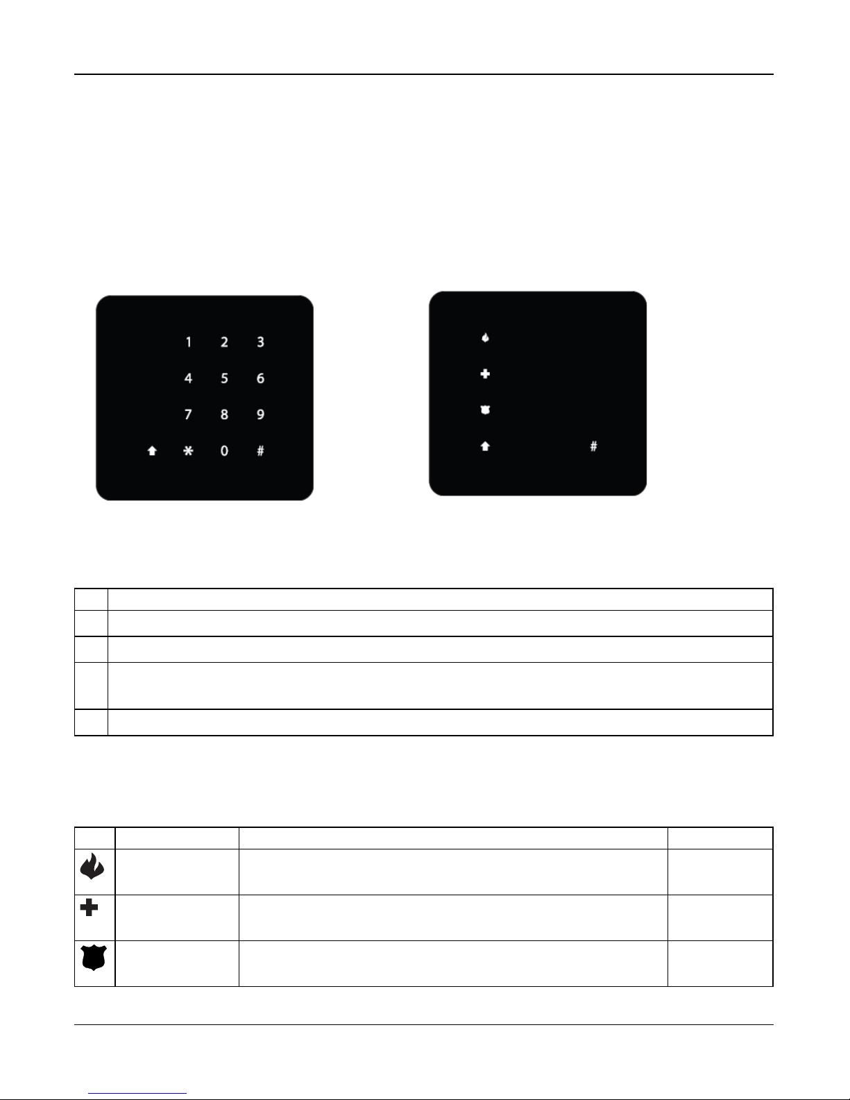
3.1 Using the Integrated Keypad
The iotega includes a built-in, touch sensitive keypad that activates by proximity. From the keypad, users can arm and dis-
arm the system, view system troubles, and activate the Fire (F), Auxiliary (A) and Panic (P) keys.
The integrated keypad can be configured to work on any partition.
Figure 3-1 Keypad - Normal Operating Mode Figure 3-2 Keypad - Shift Mo de
3.1.1 Key Functions
The following keys are enabled during normal operating mode:
Key Description
(0-9) numeric entry (access code)
# clear entries, return to previous screen
* [*] 2 for Troubles, see on page 45.
[*] 8 to enable WiFi access point (for adding IP devices such as the touchscreen keypad). See on the facing page.
↑
Shift mode switches between numeric and Emergency keys
3.1.2 Emergency Keys
The Fire, Auxiliary and Panic keys can be enabled independently by the installer. All three are enabled by default. The
Emergency keys behave as follows:
Key Alarm Type Indication Reporting Code
Fire Keypad beeps 3 times. Siren sounds. Signal sent to monitoring station Fire Alarm (if pro-
grammed)
Auxiliary Keypad beeps 3 times when activated and 10 times when the event is suc-
cessfully received by the central monitoring station.
Auxiliary alarm
Panic Keypad beeps three times and a signal is sent to the monitoring station.
Can be configured as audible or silent
Panic alarm
- 13 -

Section 3: Operation
To use the Emergency keys:
1. Press the Shift key (↑). The Emergencykeys are illuminated (if enabled ). If an Emergency key is not pressed within
10 seconds, the keypad returns to normal operating mode.
2. Press and hold an Emergency key for 2 seconds to activate the alarm.
3.1.3 WPS Mode ([*]8)
WPS (Wi-Fi Protected Setup) mode activates iotega‘s Wi-Fi access point to facilitate connection with IP devices, such as the
touchscreen keypad and IP cameras.
To enable WPS mode:
1. Tap [*] 8 on the integrated kaypad.
2. Enter a valid installer code.The WiFi siganl strength LED flashes to indicate the system is in WPS mode.
The WPS window expires after 2 minutes or once an IP address is obtained.
Note: The Wi-Fi Client enable/disable option has priority over WPS Mode.
3.2 Arming and Disarming Methods
This section describes the arming methods available on the iotega.
3.2.1 Away Arming
Away Arming arms the entire system, including the perimeter and interior devices. The Ready light must be on to arm the
system. If the Ready light is off, ensure all protected doors and windows are secure or bypassed.
To arm the system, enter a valid access code. To disarm, enter a valid access code.
During exit delay, the Armed and Ready indicators turn on and, If the Audible Exit Delay option is enabled, the keypad
beeps once every second during the exit delay (and three times a second during the last 10 seconds) to alert the user to
leave via a delay zone. The Ready light turns off when the Exit Delay ends.
When the exit delay has expired, the system is armed as indicated by the following conditions:
l the Ready indicator turns off.
l the Armed indicator stays on.
l the panel is silent.
Note: In Away Arming mode, manually bypassed zones are logged and communicated to the central monitoring station.
3.2.2 Stay Arming
Note: Requires at least one zone defined as Interior Stay/Away or Delay Stay/Away for this function to work.
Stay Arming is intended to arm the perimeter of the premises while permitting movement within. The Ready light must be on
to arm the system. If the Ready light is off, ensure all protected doors and windows are secure or bypassed. To Stay arm the
system, enter a valid user code and stay within the premises (do NOT violate a zone programmed as Delay). The Armed
light turns on once a function key is pressed or an access code is entered. When a user code is used, the keypad beeps if
the Audible Exit Delay option is enabled. The Ready indicator turns off and the Armed indicator turns on when the exit delay
ends.
Note: In Stay Arming mode, all auto-bypassed stay/away zones are logged and communicated to the central monitoring sta-
tion.
- 14 -

Section 3: Operation
3.2.3 Quick Arming
Quick arming enables users to arm the system via touchscreen or wirefree keypad without entering an access code. This
provides a fast method of arming for regular users and allows users without an access code to arm the system. The Quick
Arming feature must be enabled in order for this function to operate. See on page 29.
3.2.4 Disarming
The user must enter through a door programmed as Delay. Upon entering, the panel emits a steady entry delay tone (and a
pulsing tone during the last 10 seconds of entry delay) to alert the user to disarm the system. To disarm the system, enter a
valid user code or use a wireless key. If an alarm occurred while the panel was armed, the keypad numbers corresponding
to the violated zones are illuminated. If the system is disarmed using a method other than the keypad (e.g., wireless key),
the panel emits three squawks to indicate alarm in memory.
- 15 -

Section 4: Programming Options
Section 4: Programming
Options
This section provides descriptions of all alarm controller
options, both programmable and read-only. Programming
options are accessed through the Installer portal.
4.1 Integrated Keypad Options
This section describes programmable options for the
iotega’s integrated keypad.
Keypad Lockout Attempt
Keypad Lockout is a security measure designed to prevent
unauthorized attempts to access the security system by lim-
iting the number of attempts to enter a valid access code.
Once the maximum number of attempts is reached, no func-
tions can be performed on the keypad for 5 minutes (Lock-
out Duration).
If the maximum number of invalid attempts is not reached
within one hour, or if a valid access code is entered, the
counter is reset.
Default: 0 (disabled)
Validrange: 0 to 255
emergency alarm reporting code to the central monitoring
station. When the emergency reporting code is received, the
keypad beeps 10 times.
Default: Enabled
Validrange: Enabled, Disabled
Panic Button
This function is used to enable or disable the Panic [P] but-
ton on the integrated keypad. When enabled, pressing and
holding the [P] button for 2 seconds sends an emergency
alarm reporting code to the central monitoring station.
Default: Enabled
Validrange: Enabled, Disabled
Internal Buzzer Control
This option is used to set the volume level of the internal
buzzer. The volume ranges from lowest (1) to highest (15).
Programming (0) turns off the buzzer.
Note: Internal buzzer volume shall be at maximum setting
for UL/ULC.
Default: 7
Validrange: 0-15
Keypad Partition Assignment
This section is used to select the partition that the built-in
keypad will operate on.
Default: 1
Validrange: 1
Fire Button Options
This function is used to enable or disable the Fire [F] button
on the integrated keypad. When enabled, pressing and hold-
ing the [F] button for 2 seconds triggers a Fire alarm. The sys-
tem sounds 3 beeps to acknowledge the valid alarm and the
siren sounds with a pulsing tone. An alarm reporting code is
transmitted to the central monitoring station.
Default: Enabled
Validrange: Enabled, Disabled
Auxiliary Button Options
This function is used to enable or disable the Auxiliary [A]
button on the integrated keypad. When enabled, pressing
and holding the [A] button for 2 seconds sends an
Keypad Lockout Duration
This section displays the length of time that the integrated
keypad remains locked after the programmed number of
access code attempts has been exceeded.
Default: 5 minutes
Validrange: Read-only
4.2 System Configuration
Options
This section describes programmable options for the alarm
controller.
System Area Label
Use this option to program a custom label for the security
system. This label is used in the event buffer when system
events occur.
Default: System Area
Validrange: 32 Characters, UTF-8 format
- 16 -

Section 4: Programming Options
System Account Number
The system account number is used to identify the alarm sys-
tem when communicating system events to the central mon-
itoring station. The system account number can be either 4
or 6 digits long. Program a 6-digit code only when using the
SIA reporting format. SIA uses this account number for all
partitions and system events. All other reporting formats use
a 4-digit system account number to report system main-
tenance (e.g., low battery, zone fault) and test transmission
events. To program a 4-digit system account number, enter
4 digits followed by FF.
Note: This field is mandatory for communication with the
central monitoring station.
Default: FFFFFF (disabled)
Validrange: 000001 to FF FF FF (Hexadecimal)
Event Reporting Format
Use this programming option to assign a communicator
format for transmitting zone alarms, tampers, faults and other
signals to the central monitoring station
The following communicator formats are available:
Contact ID
Each of the digits indicate specific information about the sig-
nal. For example, if zone 1 is an entry/exit point, the event
code contains [34]. The central monitoring station would
receive the following:
*BURG - ENTRY/EXIT - 1 where the “1” indicates which
zone went into alarm.
SIA Format - Level 2 (Hard Coded)
The SIA communication format used in this product follows
the level 2 specifications of the SIA Digital Communication
Standard - October 1997. This format sends the account
code along with its data transmission. The transmission
appears similar to the following at the receiver:
N ri1 BA 01
N = New Event
ri1 = Partition /Area Identifier
BA = Burglary Alarm
01 = Zone 1
A system event uses the Area Identifier ri00.
Default: SIA
Validrange: SIA, CID
Bell Squawk on Arming
With this option enabled, the iotega chirps the sirens briefly
at full volume when the system is successfully armed. The
following options are provided to customize this option:
None: Sirens do not chirp when the system is armed.
All RF: Sirens chirp when armed by any wireless device.
RF Wireless Key: Sirens chirp only when armed by a wire-
less key.
RF Keypad: Sirens chirp only when armed by a wirefree
keypad.
Default: RF WirelessKey
Validrange: None, AllRF, RF WirelessKey, RF Keypad
Chime on Zone Opening
When this option is enabled, the door chime sounds each
time an appropriately configured zone is opened.
The Door Chime attribute must be set to ON for every zone
that requires a chime on opening.
Default: Enabled
Validrange: Enabled, Disabled
Chime on Zone Closing
When this option is enabled, the door chime sounds each
time an appropriately configured zone is closed.
The Door Chime attribute must be set to ON for every zone
that requires a chime on opening.
Default: Disabled
Validrange: Enabled, Disabled
Trouble Beeps Are Silent
When this option is enabled, trouble beeps are sounded for
one minute and then auto silenced for any trouble condition.
For Fire/CO troubles, trouble beeps sound every 10 seconds
for the duration of the trouble.
If the system is armed at the time that the trouble occurs, the
indication is auto silenced. When the system is disarmed,
the trouble beeps sound for 1 minute but can be silenced by
pressing any key. Once silenced, the beeps will not restart.
If a trouble has occurred and has been silenced, and
another trouble of the same type occurs, the trouble beeps
restart. (e.g., Zone tamper on Zone 1 is silenced, Zone
tamper on Zone 2 restarts trouble beeps).
If disabled, the system announces troubles through the
keypad buzzer every 10 seconds. Pressing any key on the
keypad silences the trouble beeps; however, new troubles
- 17 -

Section 4: Programming Options
will restart trouble beeps. For troubles that have been
silenced but are still present, trouble beeps restart daily at
7am.
Default: Disabled
Validrange: Enabled, Disabled
Burglary Bell Time-out
This option determines the length of time the system siren
sounds for. System tampers follow this timer, but Fire alarms
and keypad buzzers do not.
4 Minutes
Default:
Valid
range:
(Note: Burglary Bell Time-out shallbe 4 minutes for
UL/ULC)
0 to 255 Minutes
Fire Bell Time-Out
This option determines the maximum activation time for fire
alarm sirens. Each partition has a dedicated Fire Bell Time-
out timer.
Fire Bell Time-out takes priority over Burglary Bell Time-out.
Default:
Valid
range:
5 Minutes (Note: Fire Bell Time-out shallbe 5 minutes for
UL/ULC)
0 to 255 Minutes
Audible Panic
This option is used to set internal buzzer behavior when the
Panic key is pressed. When set to Audible, pressing the
Panic key causes the buzzer to sound a series of 3 beeps to
acknowledge the alarm. The buzzer then sounds a steady
tone for the length of the bell time-out or until an access
code is entered.
When set to Silent, pressing the Panic key causes the
buzzer and the bell output to remain silent, but the alarm is
still transmitted (if programmed).
Default: Silent
Validrange: Audible, Silent
Access Code Required For Bypassing
When this option is enabled, an access code is required to
view the zone bypass menu.
When this option is disabled, the zone bypass menu is
accessible to anyone.
Default: Disabled
Validrange: Enabled/Disabled
RF Jam
When this option is enabled, the alarm panel detects and
reports continuous wireless signals that could interfere with
the operation of the alarm system.
UL: The iotega detects and reports continuous RF inter-
ference using UL 20/20 requirements for wireless jam detec-
tion (20 seconds of continuous jam detection is required).
Default:
Valid
range:
Disabled (Note: RF Jam shall be enabled for UL/ULC
applications)
Disabled, UL
Installer Access Window Permission
When this option is enabled, the installer is given access to
the panel’s programming sections for a 4-hour window, or
until the install has been finalized.
When this option is disabled, the installer can access the
panel’s programming sections at any time.
This option is controlled by Level 1 users.
Default: Enabled
Validrange: Enabled, Disabled
Ethernet IP Address
This is the resolved value based on the DHCP address
assignment.
Default: 000.000.000.000
Validrange: Read-only
Ethernet IP Subnet
This is the resolved value based on the DHCP address
assignment.
Default: 255.255.255.000
Validrange: Read-only
Gateway IP Address
This is the resolved value based on the DHCP address
assignment.
Default: 000.000.000.000
Validrange: Read-only
DNS 1 IP Address
This is the resolved value based on the DHCP address
assignment.
Default: 000.000.000.000
Validrange: Read-only
- 18 -
 Loading...