

Page 1
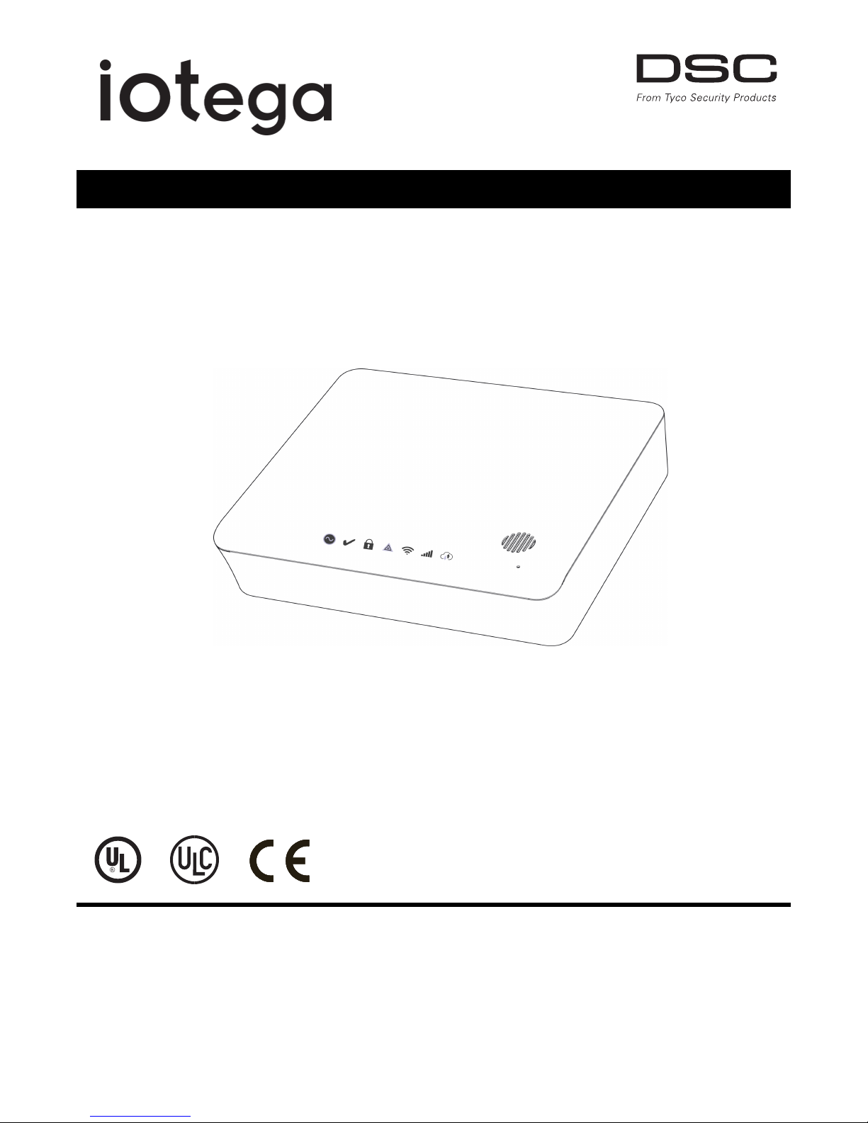
Wireless Security and Automation System
V1.0 Reference Manual
WARNING: This manual contains information on limitations regarding product use and function and information on the
limitations as to liability of the manufacturer. The entire manual should be carefully read.
Models:
WS900UL/WS901
Page 2

Table of Contents
Section 1: Introduction 2
1.1 About the System 2
1.1.1 Available Models 2
1.2 Compatible Devices List 2
1.3 Specifications 5
Section 2: Installation 7
2.1 Alarm Controller Installation 7
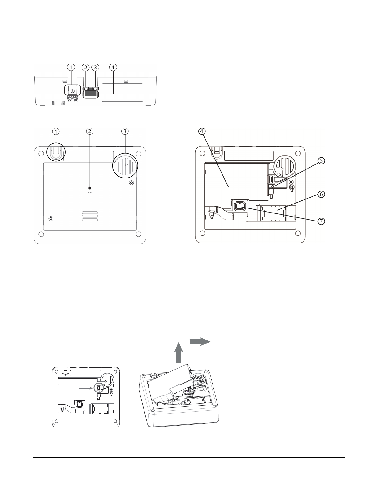
Figure 2-1 Panel Connections 8
Figure 2-2 Panel Bottom 8
Figure 2-3 Battery Compartment 8
Figure 2-4 Battery Removal 8
2.2 Controls and Indicators 9
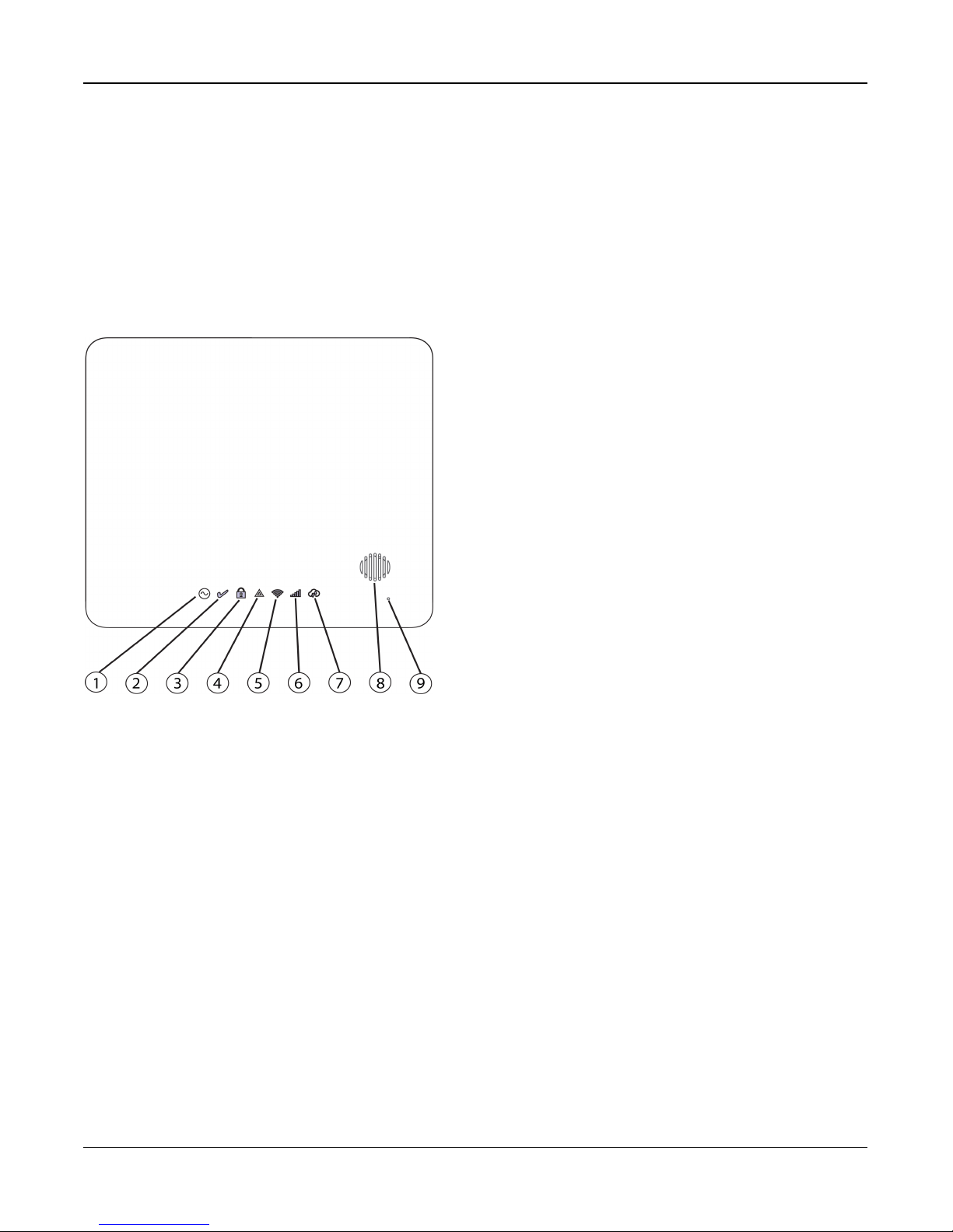
Figure 2-5 LED Indicators 9
2.3 Enrolling Wireless PowerG Security Devices 12
Section 3: Operation 13
3.1 Using the Integrated Keypad 13
Figure 3-1 Keypad - Normal Operating Mode 13
Figure 3-2 Keypad - Shift Mode 13
3.1.1 Key Functions 13
3.1.2 Emergency Keys 13
3.1.3 WPS Mode ([*]8) 14
3.2 Arming and Disarming Methods 14
3.2.1 Away Arming 14
3.2.2 Stay Arming 14
3.2.3 Quick Arming 15
3.2.4 Disarming 15
Section 4: Programming Options 16
4.1 Integrated Keypad Options 16
4.2 System Configuration Options 16
4.2.1 Reporting Configuration Options 21
4.2.2 Network Configuration Options 22
4.3 Central Monitoring Station Programming Options 23
4.3.1 Other Communicator Related Options 26
4.4 2-Way Voice Options 28
4.5 Partition Configuration Options 28
4.6 Wireless Device Configuration Options 30
4.6.1 Wirefree Keypad Configuration Options 30
4.6.2 User Configuration Options 31
4.6.3 Wireless Siren Configuration Options 32
4.6.4 Wireless Key Configuration Options 33
4.6.5 Wireless Smoke and CO Configuration Options 33
4.6.6 Wireless Glassbreak Configuration Options 34
- 2 -
Page 3

4.6.7 Wireless Temperature Configuration Options 35
4.6.8 Wireless Flood Configurations 36
4.6.9 Wireless PIR CAM Configurations 37
4.6.10 Wireless PIR (NO CAM) Configurations 38
4.6.11 Wireless Door Window Configurations 39
4.6.12 Wireless Shock Sensor Configurations 40
4.6.13 Repeater Configuration Options 41
4.7 Available Zone Types 42
4.8 Available Zone Attributes 43
4.9 Diagnostics - Read Only 43
4.10 System Control 43
4.10.1 Device 44
4.10.2 Network 44
Section 5: Troubleshooting 45
5.1 Testing: 45
5.2 Viewing Troubles from the Integrated Keypad 45
5.3 Network Troubleshooting 47
Appendix 1: Guidelines for Locating Smoke Detectors and CO Detectors 48
Appendix 2: Reporting Codes 51
Appendix 3: Regulatory Information 57
Appendix 3: EULA 62
Appendix 4: Limited Warranty 63
Appendix 5: WARNING: Installer please read carefully 64
- 3 -
Page 4

iotega Wireless Security and Automation System
Safety Instructions for Service Persons
Warning: When using equipment connected t o the telephone network, always follow
the basic safety instructions provided with this product. Save these instructions for
future reference. Inform the end-user of the safety precautions t hat must be observed
when operating t his equipment.
Before Installing The Equipment
Ensure your package includes the following items:
l Installation and User manuals, includingthe SAFETY INSTRUCTIONS.
READ and SAVE these instructions!
Follow all WARNINGS AND INSTRUCTIONS specified within this doc-
ument and/or on t he equipment.
l iotega alarm controller
l Power Supply, direct plug-in
l Ethernet cable
Selecting A Suitable Location For The Alarm Controller
Use the following list as a guide t o find a suitable location to install t his equipment:
l Locate near a power outlet.
l Select a location free from vibration and shock.
l Place alarm controller on aflat, stable surface and follow the inst allation
instructions.
Do NOT locate t his product where people may walk on the secondary circuit cable(s).
Do NOT connect alarm controller t o electrical the same circuit as largeappliances.
Do NOT select a location that exposes your alarm controller to direct sunlight, excess-
ive heat, moisture, vapors, chemicals or dust.
Do NOT inst all t his equipment near water. (e.g., bath tub, kitc hen/laundry sink, wet
basement, neara swimming pool).
Do NOT inst all t his equipment and accessories in areas whererisk of explosion
exists.
Do NOT connect this equipment to electrical outlets controlled by wall switches or
automatic timers.
AVOID interference sources.
AVOID installing equipment near heaters, air conditioners, ventilators, and
refrigerators.
AVOID locating equipment c lose to or on top of large metal objects (e.g., wall
studs).
See "Locating Detectors and Escape Plan" on page 1 for information onlocating
smoke and CO detectors.
SAFETY Precautions Required During Installation
l NEVER install this equipment during a lightning storm.
l Position c ables so that accidents can not occur. Connected cables must
NOT be subject to excessive mechanical strain.
l Use only the power supply provided with this equipment. Use of unauthorized
power supplies may cause damage.
WARNING: THIS EQUIPMENT HAS NO MAINS ON/OFF SWITCH. THE
PLUG OF THE DIRECT PLUG-IN POWER SUPPLYIS INTENDED TO
SERVE AS THE DISCONNECTING DEVICE IF T HE EQUIPMENT MUST
BE QUICKLY DISCONNECTED. IT IS IMPERATIVE THAT ACCESS TO
THE MAINS PLUG AND ASSOCIATED MAINS SOCKET/OUTLET IS
NEVER OBSTRUCTED.
IMPORTANT NOTE FORNORTHAMERICA!
This alarm system must be installed and used within an environment that
provides the pollution degree max 2 and over-voltages category II NONHAZARDOUS LOCATIONS, indoor only. The equipment is DIRECT
PLUG-IN (external transformer) and is designed to be installed, serviced
and/or repaired by service persons only; [service person is defined as a
person having the appropriate technical training and experience necessary
to be aware of hazards to which that person maybe exposed in performing
a taskand of measures to minimize the risks to that person or other
persons]. Thisequipment has no mains on/off switch; if the equipment must
be quicklydisconnected, the plug of the direct plug-in power supplyis
intended to serve as the disconnecting device; it isimperative that accessto
the mainsplug and associated mainssocket/outlet,is never obstructed.
There are no parts replaceable by the end-user within this equipment. The
wiring (cables) used for installation of the alarm system and accessories,
shallbe insulated with PVC, TFE, PTFE, FEP, Neoprene or Polyamide.
(a) Internal wiring must be routed in amanner that prevents:
- Excessive strain or loosening of wire on terminal connections;
- Damage of conductor insulation
(b) Disposal of used batteries must be made in accordance with local waste
recovery and recycling regulations.
(c) Before servicing, DISCONNECT the power.
(d) DO NOT route anywiring over circuit boards.
(e) The installer isresponsible to ensure that a readily accessible disconnect
device is incorporated in the building for permanently connected
installations.
The power supplymust be ClassII, FAIL SAFE with double or reinforced
insulation between the PRIMARY and SECONDARY
CIRCUIT/ENCLOSURE and be an approved type acceptable to the local
authorities. All national wiring rules must be observed.
IMPORTANT NOTE FORINTERNATIONALMARKET (EU,
AUS, NZ)!
This equipment is stationary-fixed and must be installed byService Persons
only (Service Person isdefined asa person having the appropriate technical
training and experience necessary to be aware of hazards to which that
person may be exposed in performing a task and of measures to minimize
the risks to that person or other persons). It must be installed and used
within an environment that providesthe pollution degree max 2, over
voltagescategory II, in non-hazardous, indoor locationsonly. When using
equipment connected to the mains and/or to the telecommunication
network, there are basic safety instructions that should always be followed.
Refer to the safety instructions provided with thisproduct and save them for
future reference. To reduce the riskof fire, electric shock and/or injury,
observe the following: Do not attempt to service this product yourself.
Opening or removing the cover mayexpose you to dangerous voltage or
other risk. Refer servicing to qualified service persons. Use authorized
accessories only with this equipment. DO NOT leave and/or depositANY
object on the top of the cabinet of this equipment! The cabinet as it is
installed on the wall is not designed to support any supplementary weight!
Do not spill any liquidson the cabinet or equipment. Do not touch the
equipment and its connected cables during an electricalstorm; there may be
a risk of electric shock. Never touchuninsulated wires or terminals unless
the equipment has been disconnected from the mains supply and from the
telecommunication network! Ensure that cables are positioned so that
accidents cannot occur. Connected cables must not be subject to excessive
mechanicalstrain. Do not use the Alarm system to report a gasleak if the
system is near a leak.
These safety instructions should not prevent you from contacting
the distributor and/or the manufacturer to obtain any further cla-
rification and/or answers to your concerns.
- 1 -
Page 5

Section 1: Introduction
Section 1: Introduction
1.1 About the System
The iotega is an easy to use, wireless security and home automation panel. iotega supports a range of wireless devices via
PowerG or Z-Wave.
Installers set up and configure the panel through a smartphone app or cloud-based portal. End users also interact with the
iotega using an intuitive smartphone app, web portal or optional wirefree and touchscreen keypads.
1.1.1 Available Models
The following alarm controller models are available:
l WS900
l WS901
Note: Not all models are available in all markets. Only WS900 supports two-way audio.
Model Differences
The table below lists the features of each alarm system model.
UL
Model PowerG (MHz) Wi-Fi (GHz)** Z-Wave (MHz)* 2-Way Audio*
WS900-19
WS900-29
WS901-14 433 2.4 No No
WS901-24EU 433 2.4 868.4 No
WS901-34EU 433 2.4 868.4 No
WS901-18 868 2.4 No No
WS901-28 868 2.4 868.4 No
WS901-24AU 433 2.4 921.4 No
WS901-34AU 433 2.4 921.4 No
*Not evaluated by UL
** 802.11b/g/n
Note: Only models withULdesignation are UL/ULC listed.
UL
UL
915 2.4 No Yes
915 2.4 908.4 Yes
1.2 Compatible Devices List
The following table lists all devices compatible with the iotega.
Note: Only models withULare UL/ULC listed. For UL/ULC certified installations use only UL/ULC listed devices.
Note: 'x' refers to detector frequency: 4 = 433MHz, 9 = 868MHz, 9 = 915MHz
Product Type Model
Modules
- 2 -
Page 6

Section 1: Introduction
Product Type Model
Touchscreen Keypad* WS9TCHW
Wirefree LCD Keypad WS9LCDWF
Cellular Communicator 3G7090/LT7090
PowerG
Wireless vanishing door/window contact PGx975
Wireless door/window contact w/ AUX PGx945
Wireless smoke detector PGx926
Wireless smoke and heat detector PGx916
Wireless CO detector PGx913
UL
UL
UL
UL
UL
PIR/Pet Immune Motion Detector PGx914
Wireless PIR motion detector PGx904(P)
Wireless PIR + camera motion detector PGx934(P)
UL
UL
Wireless Outdoor PG PIR + camera motion detector PGx944
Wireless curtain motion detector PGx924
UL
Wireless dual tech motion detector PGx984(P)
Wireless mirror motion detector PGx974(P)
Wireless outdoor motion detector PGx994
Wireless glass break detector PGx912, PGx922
Wireless shock detector PGx935
Wireless flood detector PGx985
Wireless temperature detector (indoor use) PGx905
Wireless 4-button key PGx939ULPGx929
UL
UL
UL
UL
UL**
UL**
UL
Wireless panic key PGx938
Wireless 2-button key PGx949
Wireless indoor siren PGx901
Wireless outdoor siren PGx911
Wireless repeater PGx920
UL
UL
UL
UL
IP Devices
These supplementary devices have not been evaluated by UL/ULC for compatibility with the alarm control panel.
Camera Wi-Fi IP Camera See the Smarttech portal for available
models
Touchpad Wi-Fi Touchscreen (dedicated as a system
WS9TCHW
keypad)
Phone Cellular Phone w/Wi-Fi iOS/Android based
- 3 -
Page 7
Section 1: Introduction
Z-Wave Devices
See the Smarttech portal for a complete list of supported Z-Wave devices.
Note: These supplementary devices have not been evaluated by UL/ULC for compatibility with the alarm control panel.
Central Monitoring Station Receivers
Receiver Sur-Gard System I-IP Receiver SG-System I-IP
Receiver Sur-Gard System II Receiver SG-System II
Receiver Sur-Gard System III Receiver SG-System III
Receiver Sur-Gard System IV Receiver SG-System IV
Receiver Sur-Gard System 5 Receiver SG-System 5
* Touchscreen device not evaluated by UL/ULC
**These devices shall not be used in UL/ULC listed installations.
- 4 -
Page 8

Section 1: Introduction
1.3 Specifications
Zone Configuration
l 128 wireless zones
l 18 zone types and 9 programmable zone attributes
l 4 touchscreen keypads supported (not evaluated by UL/ULC)
l 4 wirefree keypads (not evaluated by UL/ULC)
l 16 wireless sirens
l 8 wireless repeaters
l 32 wireless keys supported
l 8 wireless repeaters supported. Note that more than one wireless repeater shall be installed in a given fire alarm sig-
naling system to provide a redundant RF transmission path.
Access Codes
l Up to 100 access codes, plus one installer code and one duress code
l Programmable attributes and partition assignment for each user code
Warning Device Output
l Integral sounder capable of 85 dB @ 3m
l 2 remote, wireless indoor/outdoor warning devices supported: models PGx901 (indoor), PGx911 (outdoor)
l Programmable as steady, pulsed, temporal three (as per ISO8201) or temporal four (CO alarm)
l Warning device sounds alarms in the following priority: Fire, CO, Burglary
Memory
l 128MB RAM
l 4GB eMMC solid-state drive
l 128MB embedded FLASH memory
Power Supply - North America
Transformer:
Primary: 120VAC, 0.35A, 60Hz Class II
Secondary: 12VDC, 1.16A
Standard Battery
l Model: DSC model 17000178, 7.4V,1.0Ah lithium-Ion, rechargeable (Note: This battery pack shall not be used with
UL/ULC Household Fire Alarm Signaling system)
l Backup time: 4 hours
l Recharging time to 85%: 24 hours (UL)
l Low battery threshold: 7.3V
l Low battery restore: 7.4V
l Battery Critical Shutdown: 6.1V
l Battery lifespan: 3-5 years
Extended Battery
l Model: DSC model 17000179, 7.4V, 4.5Ah, lithium-Ion, rechargeable
l backup time: 24 hours
l Recharging time to 85%: 24 hours (UL)
l Low battery threshold: 7.3V
l Low battery restore: 7.4V
- 5 -
Page 9

Section 1: Introduction
l Battery Critical Shutdown: 6.2V
l Battery lifespan: 3-5 years
Operating Environmental Conditions
l Temperature range: UL= 0°C to +49°C (32°F-120°F), EN= -10°C to 55°C (50°F-131°F)
l Relative humidity: <93% non condensing
Alarm Transmitter Equipment (ATE) Specification
l Communications over cellular or Ethernet
l Supports SIA and Contact ID
l Complies with TS203 021-1, -2, -3 Telecom equipment requirements and EN50136-1-1, EN50136-2-1, EN50136-2-3
ATS 2
l Compliant with EN50136-1-1, EN50136-2-1 ATS2 requirements
System Supervision Features
The iotega continuously monitors a number of possible trouble conditions and provides audible and visual indication at the
keypad if a trouble is present. Trouble conditions include:
l AC power failure
l Zone trouble
l Fire trouble
l Communicator trouble
l Low battery condition
l RF jam
l Failure to communicate
l Module fault (supervisory or tamper)
Additional Features
l 2-way audio Talk/Listen support*
l Audio verification*
l Quick arming
l User, partition, module, zone and system labels
* Not evaluated by UL.
- 6 -
Page 10

Section 2: Installation
Section 2: Installation
2.1 Alarm Controller Installation
Installing the iotega consists of connecting and powering up the hardware, as well as configuring the device using the
installer portal.
An typical installation includes the following steps:
1. Install the hardware
2. Create an account for the panel
3. Assign a service plan
4. Add a gateway
5. Create a master contact
6. Enroll sensors and other devices
7. Select Go Live on the Accounts: Summary page to bring the iotega online.
8. Test panel operation
To install the iotega:
1. Locate the panel on a flat surface in close proximity to AC power and a wireless router.
2. Remove the plastic pull tab from the access cover on the back of the panel to activate the battery. If the battery is not
installed, see Installing a new Battery below.
3. Connect the Ethernet cable to the port on the back of the panel. Connect the other end of the cable to the wireless
router.
Note: For EN installations, use only the supplied Ethernet cable.
4. Connect the barrel jack of the plug-in adapter to the power connector on the back of the panel. Route the power
cable through the strain relief channel on the bottom of the panel then plug the adapter into an AC outlet. The iotega
powers up once connected to AC.
The power-up sequence is as follows:
l The integrated keypad numbers illuminate in sequence until the power up sequence is complete.
l After approximately 40 seconds the Power LED illuminates.
l The Ethernet Link Speed LED illuminates steady green and the Ethernet Link Activity LED flashes rapidly to
indicate that a connection is being made to the Tyco cloud.
l After several minutes, depending on network speed, the Remote Connection LED illuminates steady green
(or flashing green if installer access window is enabled), indicating that a connection has been established.
For more information on LED indicators, see on page 9.
Note: If the Remote Connection Status LED flashes red, the panel may be having difficulty connecting to the TycoOn serv-
ers. Restarting the panel may remedy the issue. The following UDP ports must be open: 1234, 1235, and 1236. If the prob-
lem persists, contact DSC technical support.
Note: When replacing the battery, use battery pack suitable for the application. Refer to on page 5.
- 7 -
Page 11
Section 2: Installation
Push tab
to
release
Figure 2-1 Panel Connectio ns
1. Power Connector
2. Ethernet Link Speed LED
3. Ethernet Link Activity LED
4. Ethernet Port
Figure 2-2 Panel Bottom Figure 2-3 Battery Compartment
1. Power cable Strain Relief
2. Access Cover for Battery, SIM Card and Reset Button
3. Speaker
4. Battery
5. Reset button
6. SIM card
7. Tamper switch
Removing the Battery
1. Remove the access cover from the back of the panel.
2. Push the battery retention tab in the direction of the arrow in Figure 2-4 .
3. Lift the battery from the front, then pull up and slide out.
Figure 2-4 Battery Removal
- 8 -
Page 12
Section 2: Installation
Installing a new battery
1. Remove the access cover from the back of the panel.
2. Insert the battery, back end first, as shown in Figure 2-4 .
3. Press the front of the battery down until the retention tab clicks into place.
4. Replace the back cover of the panel.
2.2 Controls and Indicators
The iotega provides a series of LED indicators to notify users of system status.
Figure 2-5 LED Indicators
1. Power LED
2. Ready to Arm LED
3. Armed LED
4. Trouble LED
5. WiFi Signal Strength LED
6. Cellular Signal Strength LED
7. Remote Connection LED
8. Siren
9. Microphone
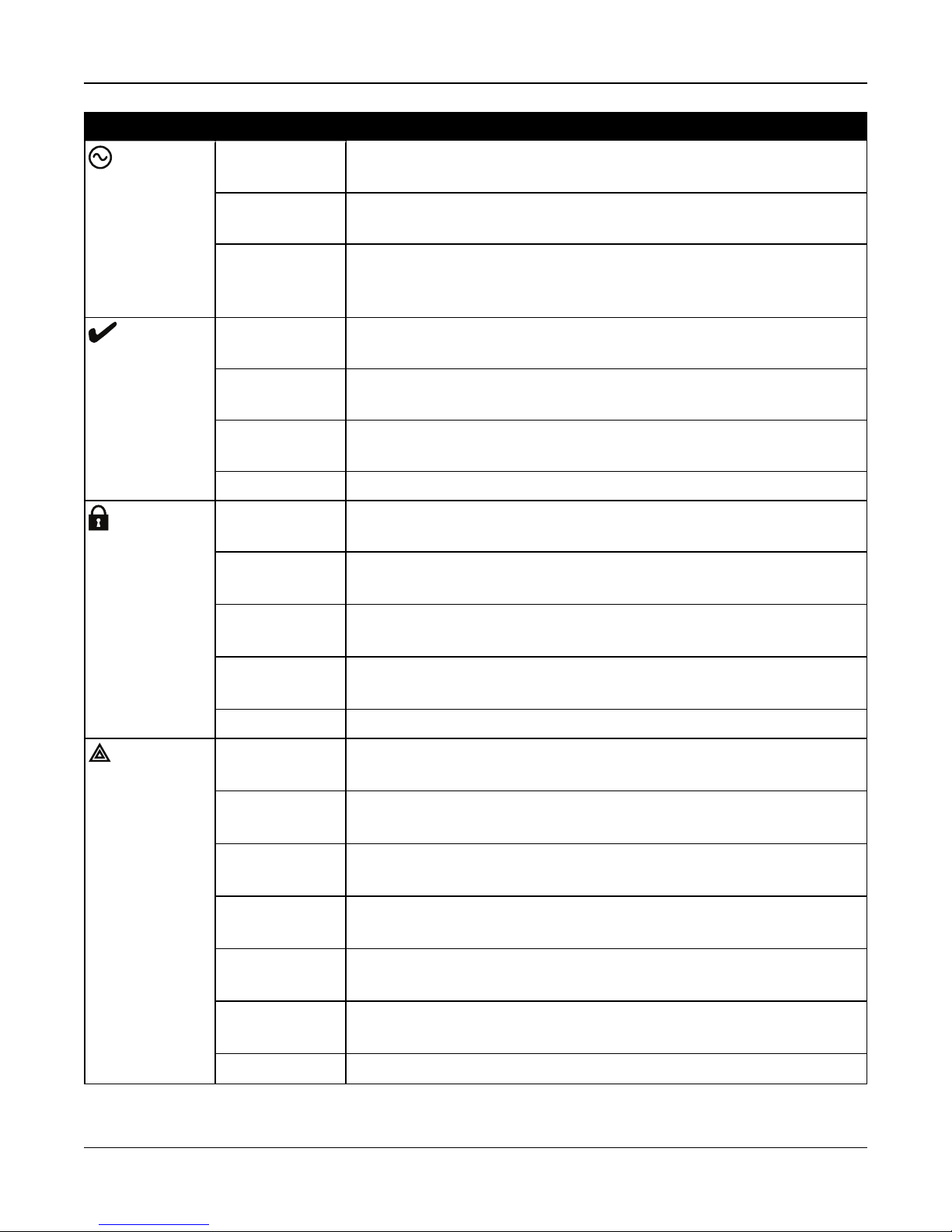
Table 2-1 LED Indicator Operation
- 9 -
Page 13
Section 2: Installation
LED Indicator Description
Power
Ready
Armed
ON Steady
AC power is currently connected to the system.
[Green]
Flashing [Amber] System Test
(All status LEDs flashing at same time)
OFF · System is not powered On
· NO AC connected, and system operating on backup battery
· NO AC connected and backup battery is discharged.
ON Steady
System is ready to arm.
[Green]
OFF System is not ready to arm. Not all zones are secure or a Fire or CO alarm is
present.
Flashing [Amber] System Test (AC, Ready, Trouble, Arm LED’s, WiFi Trouble, Cellular Trouble &
System remote status flashing at same time)
Flashing [Green] Installer Walk Test (Ready, Trouble and Arm LED’s flashing at same time)
ON Steady
Partition is armed.
[Red]
Flashing
System in Alarm. [Note: this LED does not flash for silent alarms or panic alarms
[Red]
Trouble
Flashing
[Amber]
Flashing
System Test (AC, Ready, Trouble, Arm LED’s, WiFi Trouble, Cellular Trouble &
System remote status flashing at same time)
Installer Walk Test (Ready, Trouble and Arm LED’s flashing at same time)
[Red]
OFF Partition is disarmed or audible alarm annunciation is deactivated.
ON Steady
System trouble is present
[Yellow]
Single flash
[*][2] System Trouble menu is accessed
[Yellow]
Two flashes
System In second level sub-menu
[Yellow]
Three Flashes
System In third level sub-menu
[Yellow]
Flashing
[Amber]
Flashing
System Test (AC, Ready, Trouble, Arm LED’s, WiFi Trouble, Cellular Trouble &
System remote status flashing at same time)
Installer Walk Test (Ready, Trouble and Arm LED’s flashing at same time)
[Yellow ]
OFF No system troubles
- 10 -
Page 14
Section 2: Installation
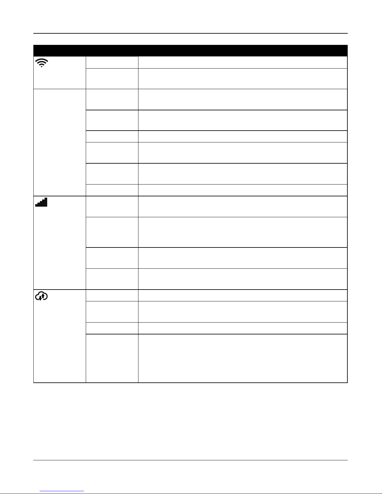
LED Indicator Description
Wi-Fi Signal
Strength
Cellular Sig-
nal Strength
ON Steady [Green] Strong Signal Connection
ON Flashing
[Green]
ON Steady
[Yellow]
ON Flashing [Yel-
low]
On Steady [Red] No Signal
Flashing
[Red]
Flashing
[Amber]
OFF WiFi disabled
ON Steady [Green] Strong signal connection
ON Steady
[Yellow]
Wi-Fi active in WSA mode (for AP mode)
Weak Signal Connection
Z-Wave enrollment mode
Hardware Network reset
System Test (AC, Ready, Trouble, Arm LED’s, WiFi Trouble, Cellular Trouble &
System Remote Status flashing at same time)
Weak signal connection
Remote Con-
nection Status
ON Steady
[Red]
Flashing
[Amber]
ON Steady [Green] Link to remote server is active
ON Flash
[Red]
OFF Link to remote server is not active
Flashing
[Amber]
No Signal or no connection
System Test (AC, Ready, Trouble, Arm LED’s, WiFi Trouble, Cellular Trouble &
System remote status flashing at same time)
Link to remote server is active but has failed to communicate
System Test (AC, Ready, Trouble, Arm LED’s, WiFi Trouble, Cellular Trouble &
System Remote Status flashing at same time)
Note: If the Remote Connection status LED flashes red, the panel may be having
difficulty connecting to the remote server. Restarting the panel may remedy the
issue. If the problem persists, contact DSC technical support.
Reset Button
Pressing and holding the Reset button, located under the battery cover (see figure 3-3), for a minimum of 10 seconds per-
forms a vendor reset. WiFi configurations (client mode) are returned to default settings.
Pressing and holding the Reset button for a minimum of 20 seconds returns the following options to their default settings:
SSID, security key, security type and reconnection to DHCP.
Note: The system must be disarmed with no alarms in memory in order for the Reset button to function as described above.
- 11 -
Page 15

Section 2: Installation
Tamper Switch
The panel includes a tamper switch under the back battery cover. If the battery cover is removed while the system is dis-
armed, the tamper condition must be cleared before arming is permitted. If the battery cover is removed while the system is
armed, the bell sounds, a system tamper is logged and communicated to the central monitoring station, and a system tem-
per trouble is displayed in the Trouble menu.
2.3 Enrolling Wireless PowerG Security Devices
Device enrollment and configuration is done using the installer portal. Refer to the wireless device programming descrip-
tions on page 1.
Wireless devices are enrolled using one of the following methods:
l Manually entering a device-specific serial number then configuring the available options.
l Using auto enrollment.
To auto enroll:
1. Enable auto enroll using the installer portal.
2. Power up the wireless device and press the Enroll button until the on-board LED lights steady. The serial number is
displayed.
3. Confirm you want to enroll the device then configure the available options.
4. Submit the settings to finish enrollment.
5. Continue the above process until all devices are enrolled.
The wireless devices in the table below each have a dedicated Enroll button, located on the circuit board inside the plastic
casing. A Phillips screw must be removed on most devices to gain access. Refer to the installation instructions provided
with the device for more information.
PGx901 Indoor siren PGx924 Curtain motion detector
PGx904 PIR/Pet Immune motiondetector PGx926 Smoke detector
PGx914 PIR/Pet Immune motiondetector PGx935 Shock detector and magneticcontact
PGx905 Temperature detector PGx944 Tower Cam motion detector
PGx911 Outdoor siren PGx945 Magnetic contact with Aux.
PGx913
PGx912 Glassbreak detector PGx975 Magnetic contact (vanishing)
PGx916 Smoke and heat detector PGx984 Mirror PIR motion detector
PGx920
PGx922 Glassbreak detector PGx994 Outdoor PIR motion detector
Carbon Monoxide detector
Note: enrolls automaticallyon power-up
Wirelessrepeater
Note: hold Enroll button until red and green LEDs light steady
PGx974 Mirror PIR with anti-masking
PGx985 Flood detector
To enroll wireless keys:
PGx929/PGx939 4-button wirelesskey Press and hold [*]button until LED lightssteady then release.
PGx949 2-button wirelesskey Press and hold unlock button until LED lightssteady then release.
PGx938 Panic key Press and hold button until LED lights steady then release.
- 12 -
Page 16
Section 3: Operation
Section 3: Operation
This section describes how to use the iotega‘s integrated keypad.
3.1 Using the Integrated Keypad
The iotega includes a built-in, touch sensitive keypad that activates by proximity. From the keypad, users can arm and dis-
arm the system, view system troubles, and activate the Fire (F), Auxiliary (A) and Panic (P) keys.
The integrated keypad can be configured to work on any partition.
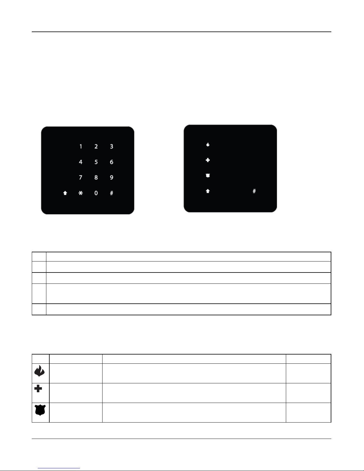
Figure 3-1 Keypad - Normal Operating Mode Figure 3-2 Keypad - Shift Mo de
3.1.1 Key Functions
The following keys are enabled during normal operating mode:
Key Description
(0-9) numeric entry (access code)
# clear entries, return to previous screen
* [*] 2 for Troubles, see on page 45.
[*] 8 to enable WiFi access point (for adding IP devices such as the touchscreen keypad). See on the facing page.
↑
Shift mode switches between numeric and Emergency keys
3.1.2 Emergency Keys
The Fire, Auxiliary and Panic keys can be enabled independently by the installer. All three are enabled by default. The
Emergency keys behave as follows:
Key Alarm Type Indication Reporting Code
Fire Keypad beeps 3 times. Siren sounds. Signal sent to monitoring station Fire Alarm (if pro-
grammed)
Auxiliary Keypad beeps 3 times when activated and 10 times when the event is suc-
cessfully received by the central monitoring station.
Auxiliary alarm
Panic Keypad beeps three times and a signal is sent to the monitoring station.
Can be configured as audible or silent
Panic alarm
- 13 -
Page 17

Section 3: Operation
To use the Emergency keys:
1. Press the Shift key (↑). The Emergencykeys are illuminated (if enabled ). If an Emergency key is not pressed within
10 seconds, the keypad returns to normal operating mode.
2. Press and hold an Emergency key for 2 seconds to activate the alarm.
3.1.3 WPS Mode ([*]8)
WPS (Wi-Fi Protected Setup) mode activates iotega‘s Wi-Fi access point to facilitate connection with IP devices, such as the
touchscreen keypad and IP cameras.
To enable WPS mode:
1. Tap [*] 8 on the integrated kaypad.
2. Enter a valid installer code.The WiFi siganl strength LED flashes to indicate the system is in WPS mode.
The WPS window expires after 2 minutes or once an IP address is obtained.
Note: The Wi-Fi Client enable/disable option has priority over WPS Mode.
3.2 Arming and Disarming Methods
This section describes the arming methods available on the iotega.
3.2.1 Away Arming
Away Arming arms the entire system, including the perimeter and interior devices. The Ready light must be on to arm the
system. If the Ready light is off, ensure all protected doors and windows are secure or bypassed.
To arm the system, enter a valid access code. To disarm, enter a valid access code.
During exit delay, the Armed and Ready indicators turn on and, If the Audible Exit Delay option is enabled, the keypad
beeps once every second during the exit delay (and three times a second during the last 10 seconds) to alert the user to
leave via a delay zone. The Ready light turns off when the Exit Delay ends.
When the exit delay has expired, the system is armed as indicated by the following conditions:
l the Ready indicator turns off.
l the Armed indicator stays on.
l the panel is silent.
Note: In Away Arming mode, manually bypassed zones are logged and communicated to the central monitoring station.
3.2.2 Stay Arming
Note: Requires at least one zone defined as Interior Stay/Away or Delay Stay/Away for this function to work.
Stay Arming is intended to arm the perimeter of the premises while permitting movement within. The Ready light must be on
to arm the system. If the Ready light is off, ensure all protected doors and windows are secure or bypassed. To Stay arm the
system, enter a valid user code and stay within the premises (do NOT violate a zone programmed as Delay). The Armed
light turns on once a function key is pressed or an access code is entered. When a user code is used, the keypad beeps if
the Audible Exit Delay option is enabled. The Ready indicator turns off and the Armed indicator turns on when the exit delay
ends.
Note: In Stay Arming mode, all auto-bypassed stay/away zones are logged and communicated to the central monitoring sta-
tion.
- 14 -
Page 18

Section 3: Operation
3.2.3 Quick Arming
Quick arming enables users to arm the system via touchscreen or wirefree keypad without entering an access code. This
provides a fast method of arming for regular users and allows users without an access code to arm the system. The Quick
Arming feature must be enabled in order for this function to operate. See on page 29.
3.2.4 Disarming
The user must enter through a door programmed as Delay. Upon entering, the panel emits a steady entry delay tone (and a
pulsing tone during the last 10 seconds of entry delay) to alert the user to disarm the system. To disarm the system, enter a
valid user code or use a wireless key. If an alarm occurred while the panel was armed, the keypad numbers corresponding
to the violated zones are illuminated. If the system is disarmed using a method other than the keypad (e.g., wireless key),
the panel emits three squawks to indicate alarm in memory.
- 15 -
Page 19

Section 4: Programming Options
Section 4: Programming
Options
This section provides descriptions of all alarm controller
options, both programmable and read-only. Programming
options are accessed through the Installer portal.
4.1 Integrated Keypad Options
This section describes programmable options for the
iotega’s integrated keypad.
Keypad Lockout Attempt
Keypad Lockout is a security measure designed to prevent
unauthorized attempts to access the security system by lim-
iting the number of attempts to enter a valid access code.
Once the maximum number of attempts is reached, no func-
tions can be performed on the keypad for 5 minutes (Lock-
out Duration).
If the maximum number of invalid attempts is not reached
within one hour, or if a valid access code is entered, the
counter is reset.
Default: 0 (disabled)
Validrange: 0 to 255
emergency alarm reporting code to the central monitoring
station. When the emergency reporting code is received, the
keypad beeps 10 times.
Default: Enabled
Validrange: Enabled, Disabled
Panic Button
This function is used to enable or disable the Panic [P] but-
ton on the integrated keypad. When enabled, pressing and
holding the [P] button for 2 seconds sends an emergency
alarm reporting code to the central monitoring station.
Default: Enabled
Validrange: Enabled, Disabled
Internal Buzzer Control
This option is used to set the volume level of the internal
buzzer. The volume ranges from lowest (1) to highest (15).
Programming (0) turns off the buzzer.
Note: Internal buzzer volume shall be at maximum setting
for UL/ULC.
Default: 7
Validrange: 0-15
Keypad Partition Assignment
This section is used to select the partition that the built-in
keypad will operate on.
Default: 1
Validrange: 1
Fire Button Options
This function is used to enable or disable the Fire [F] button
on the integrated keypad. When enabled, pressing and hold-
ing the [F] button for 2 seconds triggers a Fire alarm. The sys-
tem sounds 3 beeps to acknowledge the valid alarm and the
siren sounds with a pulsing tone. An alarm reporting code is
transmitted to the central monitoring station.
Default: Enabled
Validrange: Enabled, Disabled
Auxiliary Button Options
This function is used to enable or disable the Auxiliary [A]
button on the integrated keypad. When enabled, pressing
and holding the [A] button for 2 seconds sends an
Keypad Lockout Duration
This section displays the length of time that the integrated
keypad remains locked after the programmed number of
access code attempts has been exceeded.
Default: 5 minutes
Validrange: Read-only
4.2 System Configuration
Options
This section describes programmable options for the alarm
controller.
System Area Label
Use this option to program a custom label for the security
system. This label is used in the event buffer when system
events occur.
Default: System Area
Validrange: 32 Characters, UTF-8 format
- 16 -
Page 20

Section 4: Programming Options
System Account Number
The system account number is used to identify the alarm sys-
tem when communicating system events to the central mon-
itoring station. The system account number can be either 4
or 6 digits long. Program a 6-digit code only when using the
SIA reporting format. SIA uses this account number for all
partitions and system events. All other reporting formats use
a 4-digit system account number to report system main-
tenance (e.g., low battery, zone fault) and test transmission
events. To program a 4-digit system account number, enter
4 digits followed by FF.
Note: This field is mandatory for communication with the
central monitoring station.
Default: FFFFFF (disabled)
Validrange: 000001 to FF FF FF (Hexadecimal)
Event Reporting Format
Use this programming option to assign a communicator
format for transmitting zone alarms, tampers, faults and other
signals to the central monitoring station
The following communicator formats are available:
Contact ID
Each of the digits indicate specific information about the sig-
nal. For example, if zone 1 is an entry/exit point, the event
code contains [34]. The central monitoring station would
receive the following:
*BURG - ENTRY/EXIT - 1 where the “1” indicates which
zone went into alarm.
SIA Format - Level 2 (Hard Coded)
The SIA communication format used in this product follows
the level 2 specifications of the SIA Digital Communication
Standard - October 1997. This format sends the account
code along with its data transmission. The transmission
appears similar to the following at the receiver:
N ri1 BA 01
N = New Event
ri1 = Partition /Area Identifier
BA = Burglary Alarm
01 = Zone 1
A system event uses the Area Identifier ri00.
Default: SIA
Validrange: SIA, CID
Bell Squawk on Arming
With this option enabled, the iotega chirps the sirens briefly
at full volume when the system is successfully armed. The
following options are provided to customize this option:
None: Sirens do not chirp when the system is armed.
All RF: Sirens chirp when armed by any wireless device.
RF Wireless Key: Sirens chirp only when armed by a wire-
less key.
RF Keypad: Sirens chirp only when armed by a wirefree
keypad.
Default: RF WirelessKey
Validrange: None, AllRF, RF WirelessKey, RF Keypad
Chime on Zone Opening
When this option is enabled, the door chime sounds each
time an appropriately configured zone is opened.
The Door Chime attribute must be set to ON for every zone
that requires a chime on opening.
Default: Enabled
Validrange: Enabled, Disabled
Chime on Zone Closing
When this option is enabled, the door chime sounds each
time an appropriately configured zone is closed.
The Door Chime attribute must be set to ON for every zone
that requires a chime on opening.
Default: Disabled
Validrange: Enabled, Disabled
Trouble Beeps Are Silent
When this option is enabled, trouble beeps are sounded for
one minute and then auto silenced for any trouble condition.
For Fire/CO troubles, trouble beeps sound every 10 seconds
for the duration of the trouble.
If the system is armed at the time that the trouble occurs, the
indication is auto silenced. When the system is disarmed,
the trouble beeps sound for 1 minute but can be silenced by
pressing any key. Once silenced, the beeps will not restart.
If a trouble has occurred and has been silenced, and
another trouble of the same type occurs, the trouble beeps
restart. (e.g., Zone tamper on Zone 1 is silenced, Zone
tamper on Zone 2 restarts trouble beeps).
If disabled, the system announces troubles through the
keypad buzzer every 10 seconds. Pressing any key on the
keypad silences the trouble beeps; however, new troubles
- 17 -
Page 21

Section 4: Programming Options
will restart trouble beeps. For troubles that have been
silenced but are still present, trouble beeps restart daily at
7am.
Default: Disabled
Validrange: Enabled, Disabled
Burglary Bell Time-out
This option determines the length of time the system siren
sounds for. System tampers follow this timer, but Fire alarms
and keypad buzzers do not.
4 Minutes
Default:
Valid
range:
(Note: Burglary Bell Time-out shallbe 4 minutes for
UL/ULC)
0 to 255 Minutes
Fire Bell Time-Out
This option determines the maximum activation time for fire
alarm sirens. Each partition has a dedicated Fire Bell Time-
out timer.
Fire Bell Time-out takes priority over Burglary Bell Time-out.
Default:
Valid
range:
5 Minutes (Note: Fire Bell Time-out shallbe 5 minutes for
UL/ULC)
0 to 255 Minutes
Audible Panic
This option is used to set internal buzzer behavior when the
Panic key is pressed. When set to Audible, pressing the
Panic key causes the buzzer to sound a series of 3 beeps to
acknowledge the alarm. The buzzer then sounds a steady
tone for the length of the bell time-out or until an access
code is entered.
When set to Silent, pressing the Panic key causes the
buzzer and the bell output to remain silent, but the alarm is
still transmitted (if programmed).
Default: Silent
Validrange: Audible, Silent
Access Code Required For Bypassing
When this option is enabled, an access code is required to
view the zone bypass menu.
When this option is disabled, the zone bypass menu is
accessible to anyone.
Default: Disabled
Validrange: Enabled/Disabled
RF Jam
When this option is enabled, the alarm panel detects and
reports continuous wireless signals that could interfere with
the operation of the alarm system.
UL: The iotega detects and reports continuous RF inter-
ference using UL 20/20 requirements for wireless jam detec-
tion (20 seconds of continuous jam detection is required).
Default:
Valid
range:
Disabled (Note: RF Jam shall be enabled for UL/ULC
applications)
Disabled, UL
Installer Access Window Permission
When this option is enabled, the installer is given access to
the panel’s programming sections for a 4-hour window, or
until the install has been finalized.
When this option is disabled, the installer can access the
panel’s programming sections at any time.
This option is controlled by Level 1 users.
Default: Enabled
Validrange: Enabled, Disabled
Ethernet IP Address
This is the resolved value based on the DHCP address
assignment.
Default: 000.000.000.000
Validrange: Read-only
Ethernet IP Subnet
This is the resolved value based on the DHCP address
assignment.
Default: 255.255.255.000
Validrange: Read-only
Gateway IP Address
This is the resolved value based on the DHCP address
assignment.
Default: 000.000.000.000
Validrange: Read-only
DNS 1 IP Address
This is the resolved value based on the DHCP address
assignment.
Default: 000.000.000.000
Validrange: Read-only
- 18 -
Page 22

Section 4: Programming Options
DNS 2 IP Address
This is the resolved value based on the DHCP address
assignment.
Default: 000.000.000.000
Validrange: Read-only
Access Code Required to View/Silence Troubles
This option is used to enable and disable the need to enter
an access code before viewing system troubles.
Default:
Valid
range:
Disabled (Note: Access Code Required to View/Silence
Trouble shall be enabled for UL/ULC applications)
Enabled, Disabled
Cellular Low Signal Trouble
This option is used to determine if the system will generate a
trouble event when a weak cellular signal is detected.
When enabled, a trouble event is generated if the radio sig-
nal level falls below threshold level (average CSQ level 4 or
less).
Default: Enabled
Validrange: Enabled, Disabled
Lockout Attempts
This option is used to program the number of invalid access
code entries allowed before the keypad is locked. When
keypad lockout occurs, the system is inaccessible by keypad
for the programmed duration. If the number of invalid
attempts is not reached within one hour, or if a valid access
code is entered, the counter is reset to 0 after 5 minutes.
Each keypad keeps track of it’s own lockout count and time.
Note: The FAP keys are not locked.
Default: 0
Validrange: 0 to 255
Default: Disabled
Validrange: Enabled/Disabled
Wireless Supervisory Window
Use this option to program the time window for reception of
supervision (keep alive) signals from wireless devices
enrolled on the system. If a device does not report at least
once within the programmed time window, a hardware fault
trouble is generated.
Default: 24 Hours
Validrange: 1 Hour, 2Hours, 4Hours, 8 Hours, 12 Hours, 24 Hours
Wi-Fi Low Signal Trouble
This option is used to determine if the system will log and
report low Wi-Fi signals.
Default: Enabled
Validrange: Enabled, Disabled
Communication Cancel Window
This option is used to program the length of the Com-
munication Cancel window.
Entering an access code during the communicaiton cancel
window sends a code to the central monitoring station,
informing them that the previous event should be dis-
regarded.
The communications cancel window begins after the trans-
mission delay expires and a zone alarm is transmitted. If an
access code is entered during this window, a reporting code
is communicated and logged. If the window expires without
an access code entry or a code is entered after the window,
the communications canceled event is not logged or com-
municated.
Note: The cancel window does not start after an Emergency
key alarm.
Fire Supervision
This option is used to control system supervision of smoke,
CO and heat detectors. When this option is enabled, fire
detection devices are monitored over a four-hour period. If a
device fails to report within the four-hour window, a hard-
ware fault trouble is logged for the zone.
With this option disabled, fire detection devices follow the
programmed supervisory window up to a maximum time of
18 hours. After 18 hours, fire detection devices go into fault,
regardless of the programmed supervisory window.
Default:
Validrange:
5 Minutes (UL/ULC)
0 Minutes (Standard)
5 to 255 Minutes (UL/ULC)
0 to 255 Minutes (Standard)
Swinger Shutdown
This value defines the number of communication attempts
made before the event goes into swinger shutdown. Once
the programmed number of alarm/restore events have been
communicated for an event, no further alarm/restore events
are sent until swinger shutdown is reset. The last restore
- 19 -
Page 23

Section 4: Programming Options
event is not communicated until swinger shutdown is
cleared.
Default:
Validrange:
002 (UL/ULC)
003 (Standard)
001 to 006 (UL/ULC)
000-014 (Standard)
Communication Delay
This value defines the delay before an alarm is transmitted.
The delay is for zones which have the Transmission Delay
attribute enabled. Each partition shares the same active
timer. If the delay is already active due to an alarm on a dif-
ferent partition, any new activity on another partition does
not restart the communications delay timer. Burglary Verified
events are postponed until after the transmission delay
expires. When a valid disarming procedure is used while the
transmission delay is active, a communications canceled
message is briefly displayed on the keypad when the delay
is canceled.
Default:
Validrange:
030 Seconds (UL/ULC)
000 (Standard)
000 to 045 Seconds (UL/ULC)
000-255 Seconds (Standard)
AC Failure Communication Delay
This value determines the delay before an AC failure or AC
restore is reported. The AC failure or restore is still displayed
immediately.
Default: 030 Minutes
Validrange: 000 to 255 Minutes
Wireless LowBattery Communication Delay
When a zone reports a low battery condition, the trouble is
indicated immediately on the keypad, but the transmission to
the monitoring station and logging to the event buffer is
delayed by the number of days programmed in this section.
If the low battery condition is not corrected before the delay
expires, the low battery condition is transmitted and logged
to the event buffer. The Low Battery Restore transmission is
not delayed.
Default: 007 days
Validrange: 000 to 255 days
[A] Key Alarm control (for 2-way Voice)
When this option is enabled, a 2-way talk/listen-in session is
initiated when the Auxiliary [A] key is tapped.
Default: Enabled
Validrange: Enabled, Disabled
[P] Key Alarm Control (for 2-way Voice)
When this option is enabled, a 2-way talk/listen-in session is
initiated when the Panic [P] key is tapped. Note that the [P]
key must be programmed as audible in order to initiate 2-
way audio. If the [P] key is programmed as silent, a listen-in
only session is initiated when the Panic [P] key is tapped.
Default: Enabled
Validrange: Enabled, Disabled
Duress Alarm Control (for 2-way Voice)
When this option is enabled, a Listen-in session is initiated
when a Duress alarm occurs.
Default: Enabled
Validrange: Enabled, Disabled
Wireless Siren Control During 2-way Voice
When this option is enabled and an audible alarm is
present, the wireless siren activates during a 2-way audio
session.
When disabled, the wireless siren is silent when a 2-way
audio session begins. This allows the user to better hear the
operator. The sounder resumes operation for the timeout dur-
ation if the panel has not been disarmed at the end of the 2-
way session.
Default: Enabled
Validrange: Enabled, Disabled
New Alarms Disconnect 2-Way Audio
When this option is enabled, a listen in/2-way audio session
in progress is disconnected in favor of the incoming alarm.
This option is useful when using a 2G network, as voice (2-
way audio) and data (alarm) sessions cannot take place at
the same time.
Note: Fire/CO alarms override this option and force a dis-
connect (if necessary) in order to communicate the event.
When this option is disabled, new alarms do not disconnect
2-way audio. If a new alarm is generated during the first 70
seconds of the two-way voice interval, the monitoring station
- 20 -
Page 24

Section 4: Programming Options
operator has 20 seconds to begin another two-way voice
interval.
If the new alarm is generated during the last 20 seconds of
the two-way voice interval, the monitoring station operator
has the remainder of the interval to begin another two-way
voice interval.
Default: Disabled
Validrange: Enabled/Disabled
4.2.1 Reporting Configuration Options
Open/Close
When this option is enabled, the following open/close
events are reported to the central monitoring station when
they occur. When disabled, open/close events are not repor-
ted.
l Away Arming (Close)
l Stay Arming (Close)
l Disarm (Open)
l Special Closing
l Auto Arming
l No Activity Arming
l Auto Arm Cancel Postponed
Default: Enabled
Validrange: Enabled/Disabled
Special Alarm Comms
When this option is enabled, the following special alarm
events are reported to the central monitoring station when
they occur. When disabled, special alarm events are not
reported.
l Exit Error
l Recent Closing
l Local keypad Lockout
l Remote Lockout
Default: Enabled
Validrange: Enabled/Disabled
Maintenance
When this option is enabled, the following maintenance
events are reported to the central monitoring station when
they occur. When disabled, maintenance events are not
reported.
l Event Buffer Full
l Close Delinquency
l Cold Start
l Installer Lead In/Out
l FW Update(Begin, Successful, Fail)
Default: Enabled
Validrange: Enabled/Disabled
System-Wide Troubles
When this option is enabled, the following system trouble
events are reported to the central monitoring station when
they occur. When disabled, system trouble events are not
reported.
l AC Loss and restore
l Battery trouble and restore
l Tamper and restore
l Hardware fault and restore
l RF Jam trouble and restore
l Loss of time trouble and restore
l Supervisiontrouble and restore
l Not networkedtrouble and restore
l Fire/CO trouble and restore
l Tamper trouble and restore
l Receiver not available trouble and restore
l FTC trouble and restore
l Receiver supervisiontrouble and restore
l Cellular trouble and restore
l Ethernet/WiFi trouble and restore
l Remote shoutdown trouble and restore
Default: Enabled
Validrange: Enabled/Disabled
Alarms
The following alarm events are reported to the central mon-
itoring station when they occur:
l Zone Alarm (including Heat/Freeze trouble)
l Alarm Cancel
l Duress Alarm
l Opening After Alarm
l Burglary Verified
l Burglary Not Verified
l Emergency Key Alarm
l Recent Closing
Default: Enabled
Validrange: Read-only
- 21 -
Page 25

Section 4: Programming Options
Alarm Restoral
When this option is enabled, the following alarm restoral
events are reported to the central monitoring station when
they occur. When disabled, alarm restoral events are not
reported.
l Zone Alarm Restore
l Emergency Key Restore
Default: Enabled
Validrange: Enabled/Disabled
Test
When this option is enabled, the following test events are
reported to the central monitoring station when they occur.
When disabled, test events are not reported.
l System Test
l Installer Walk Test (Begin/End)
Default: Enabled
Validrange: Enabled/Disabled
Bypass
When this option is enabled, the following bypass events
are reported to the central monitoring station when they
occur. When disabled, bypass events are not reported.
l Bypass/Unbypass
l PartialClosing
Default: Enabled
Validrange: Enabled/Disabled
ManuallyBypassed Zones
l
l Stay Zones
l Force Arm Zones
Periodic Test Transmissions
When this option is enabled, the following test transmission
events are reported to the central monitoring station when
they occur. When disabled, test transmission events are not
reported.
l Periodic Test
l Periodic Test with Trouble
Default: Enabled
Validrange: Enabled/Disabled
selected, the iotega is automatically assigned an IP address
by the network. When
Static IP is selected, a consistent IP address is used.
Default: DHCP (Automatic)
Validrange: DHCP, StaticIP
LAN/WAN IP Address
This section is used to program a static IP address. To use a
static IP address, the option LAN/WLAN Obtain IP Address
must be set to Static IP address.
Default: 000.000.000.000
Validrange: 000.000.000.000 to 255.255.255.255
LAN/WLAN IP Subnet Mask
This section is used to program a LAN/WLAN subnet mask.
To use the subnet mask, the option LAN/WLAN Obtain IP
Address must be set to Static IP address.
Default: 255.255.255.255
Validrange: 000.000.000.000 to 255.255.255.255
LAN/WLAN Gateway IP Address
This section is used to program the IP address for the net-
work’s default gateway. To use this gateway, the option
LAN/WLAN Obtain IP Address must be set to Static IP
address.
Default: 000.000.000.000
Validrange: 000.000.000.000 to 255.255.255.255
Panel's Preferred DNS Server
This section is used to program the name of the preferred
Domain Name System server.
Note: Domain Name Service (DNS) programming is not per-
mitted in UL/ULC listed systems
Note: To use the panel’s preferred DNS server, the option
LAN/WLAN Obtain IP Address must be set to Static IP
address.
Default: 000.000.000.000
Validrange: 000.000.000.000 to 255.255.255.255
4.2.2 Network Configuration Options
LAN/WAN Obtain IP Address
This option is used to determine how an IP address for
LAN/WAN communication is obtained. When DHCP is
Panel's Alternate DNS Server
This section is used to program the name of an alternate
Domain Name System server to be used if the preferred
DNS server is unavailable.
- 22 -
Page 26

Section 4: Programming Options
Note: Domain Name Service (DNS) programming is not per-
mitted in UL/ULC listed systems
Note: To use the panel’s alternate DNS server, the option
LAN/WLAN Obtain IP Address must be set to Static IP
address.
Default: 000.000.000.000
Validrange: 000.000.000.000 to 255.255.255.255
WiFi Country Code
This option is used to select the country of operation for the
alarm system.
Default: CA (Canada)
Validrange: US, AU, CA, UK, FR, SE, IL, None
WLAN SSID
This section is used to program a network name (unique
identifier) for the panel.
Default: None
Validrange: Alphanumeric
WLAN Client Control
This option is used to control WiFi client mode.
Default: Enabled
Validrange: Enabled/Disabled
WLAN Security Type
This option is used to select which encryption protocol the
system uses to secure the wireless network.
Default: WPA2 PSK AES
WPA PSK TKIP
WPA PSK AES
WPA PSK TKIP AES
WPA2 PSK TKIP
Validrange:
WPA2 PSK AES
WPA2 PSK TKIP AES
MIXED MODE TKIP
MIXED MODE AES
MIXED MODE TKIP AES
WLAN Security Key
This section is used to program a password for the Wi-Fi net-
work.
Default: None
Validrange: 32 character ACCII
Panel's Cellular Public APN
This section is used to program the Access Point Name of
the network used for cellular-data connectivity.
Default: Blank
Validrange: 32 ASCII characters or Null
Panel's Cellular Login User Name
This section is used to program a user name for cellular net-
work connection.
Default: Blank
Validrange: 32 ASCII characters or Null
Panel's Cellular Login Password
This section is used to program a user password for cellular
network connection.
Default: Blank
Validrange: 32 ASCII characters or Null
Time Zone
This option defines the time zone that the alarm system will
operate in. From the list of valid entries, locate and select the
appropriate time zone.
Default: US Eastern
US-Alaska, US-Aleutian, US-Arizona, US-Central, US-
Eastern, US-Hawaii,US-Indiana-East, US-Indiana-Starke,
Valid
range:
US-Michigan, US-Mountain, US-Pacific, US-Samoa, CA-
Atlantic, CA-Central, CA-Eastern, CA-Mountain, CA-New-
foundland, CA-Pacific, CA-Saskatchewan, CA-Saskat-
chewan-East, CA-Yukon
4.3 Central Monitoring Station
Programming Options
The following section provides descriptions of all pro-
gramming options for communications between the iotega
and the central monitoring station.
Communication Path
Use this option to select the method by which the panel com-
municates to the central monitoring station. Choose one of
the following:
None: The system does not communicate to the central mon-
itoring station via Ethernet or Cellular.
Ethernet: The system communicates to the central mon-
itoring station via Ethernet connection only.
- 23 -
Page 27

Section 4: Programming Options
Cellular: The system communicates to the central monitoring
station via cellular connection only.
Ethernet and Cellular: The system communicates to the cent-
ral monitoring station via Ethernet as the primary path and
cellular as the secondary path.
Default: None
Validrange: None, Ethernet, Cellular, Ethernet and Cellular
CMS Ethernet 1 Account Code
This option is used to program an account code used by the
central monitoring station to identify the ethernet transmitter.
Programming all 0’s or all F’s causes a module con-
figuration trouble.
Note: If both Ethernet Receiver 1 and Cellular Receiver 1
are the same receiver (IP and port number are identical), Eth-
ernet Receiver 1 account is used for Ethernet and Cellular.
Note: An Ethernet account code is necessary in order for the
iotega to communicate to the central monitoring station (if
Ethernet communication path is selected).
Default: 0000000000
Validrange: 0000000000 to FFFFFFFFFF
CMS Ethernet 1 DNIS
The Dialed Number Information Service (DNIS) is used in
addition to the account code to identify the communicator
module at the central monitoring station.
Default: 000000
Validrange: 000000 to 0FFFFF (first digit not used)
CMS Ethernet 1 IP Address
This option is used to program an IP address for the Eth-
ernet receiver. When a valid IP address has been pro-
grammed, Ethernet receiver 1 is enabled and will
communicate events over the Ethernet channel.
Ethernet Receiver 1 and Cellular Receiver 1 may be con-
figured to communicate to the same central monitoring sta-
tion receiver. To configure the device to operate using this
common receiver mode functionality, program Ethernet
Receiver 1 and Cellular Receiver 1, IP address and port
number with identical values.
Note: When operating in common receiver mode, Ethernet
Receiver 1 account code is used for Ethernet and Cellular.
Default: 127.000.000.001
Validrange: 000.000.000.000 to 255.255.255.255
CMS Ethernet 1 Local Port
Use this section to set the value of the local outgoing port.
Set the value of this port when the installation is located
behind a firewall and must be assigned a particular port
number as determined by the central monitoring station sys-
tem administrator.
Note: Do not program Ethernet Receiver 1 and Ethernet
Receiver 2 local ports with the same value.
Default: 3060 (0BF4)
Validrange: 0000 to 65535
CMS Ethernet 1 Remote Port
This section is used to program the port number used by Eth-
ernet 1. Set the value of this port when the installation is loc-
ated behind a firewall, and must be assigned a particular
port number as determined by the central monitoring station
system administrator.
Default: 3061 (0BF5)
Validrange: 0000 to 65535
CMS Ethernet 1 Domain Name
This information is provided by the central monitoring station
system administrator.
Default: Blank
Validrange: 32 characters ASCII
CMS Ethernet 2 Account Code
The account code is used by the central monitoring station
to distinguish between transmitters. Programming all 0’s or
all F’s causes a module configuration trouble.
Note: If both Ethernet Receiver 2 and Cellular Receiver 1
are the same receiver (IP and port number are identical), Eth-
ernet Receiver 2 account will be used for Ethernet and Cel-
lular.
Note: An Ethernet account code is necessary in order for the
iotega to communicate to the central monitoring station (if
Ethernet communication path is selected).
Default: 0000000000
Validrange: 0000000000 to FFFFFFFFFF
CMS Ethernet 2 DNIS
The Dialed Number Information Service (DNIS) is used in
addition to the account code to identify the communicator
module at the central monitoring station.
- 24 -
Page 28

Section 4: Programming Options
Default: 000000
Validrange: 000000 to FFFFFF (first digit not used)
CMS Ethernet 2 IP Address
Enter the Ethernet receiver 2 IP address. This address will
be provided by the central monitoring station system admin-
istrator. Programming the Ethernet Receiver 2 IP address
with 000.000.000.000 will disable Ethernet reporting.
Note: When a valid IP address has been programmed, Eth-
ernet Receiver 2 is enabled and will communicate events
over the Ethernet channel.
Ethernet Receiver 2 and Cellular Receiver 2 may be con-
figured to communicate to the same central monitoring sta-
tion receiver. To configure the device to operate using this
common receiver mode functionality, program the Ethernet
Receiver 2 and Cellular Receiver 2 IP address and port num-
ber with the same values. When operating in common
receiver mode the Ethernet Receiver 2 account code will be
used for communications over Ethernet and Cellular.
Note: Do not program Ethernet Receiver 1 and Ethernet
Receiver 2 to communicate to same receiver.
Default: 000.000.000.000
Validrange: 000.000.000.000 to 255.255.255.255
CMS Ethernet 2 Local Port
Use this section to set the value of the local outgoing port.
Set the value of this port when the installation is located
behind a firewall and must be assigned a particular port
number as determined by the central monitoring station sys-
tem administrator.
Change the default value of this port when the installation is
located behind a firewall and must be assigned a particular
port number as determined by the central monitoring station
system administrator.
Note: Do not program Ethernet Receiver 1 and Ethernet
Receiver 2 local ports with the same value.
port number as determined by the central monitoring station
system administrator.
Default: 3061 (0BF5)
Validrange: 0000 to 65535
CMS Ethernet 2 Domain Name
This information is provided by the central monitoring station
system administrator.
Default: Blank
Validrange: 32 characters ASCII
CMS Cellular 1 Account Code
The account code is used by the central monitoring station
to distinguish between transmitters. Programming all 0’s or
all F’s causes a module configuration Trouble.
A cellular account code is necessary in order for the iotega
to communicate to the central monitoring station (if cellular
communication path is selected).
Default: 0000000000
Validrange: 0000000000 to FFFFFFFFFF
CMS Cellular 1 DNIS
The DNIS is used in addition to the account code to identify
the communicator module at the central monitoring station.
Default: 000000
Validrange: 000000 to 0FFFFF
CMS Cellular 1 IP Address
Enter the cellular receiver 1 IP address. This information will
be provided by the central monitoring station system admin-
istrator.
Note: When a valid IP address has been entered, the cel-
lular receiver is enabled and will communicate events over
the cellular channel.
Default: 000.000.000.000
Validrange: 000.000.000.000 to 255.255.255.255
Default: 0000 to 65535
Validrange: 0000000000 to FFFFFFFFFF
CMS Ethernet 2 Remote Port
This section is used to program the port number used by Eth-
ernet 1. Set the value of this port when the installation is loc-
ated behind a firewall, and must be assigned a particular
CMS Cellular 1 Remote Port
This section determines the port used by Cellular Receiver 1
for communication to the receiver.
Note: Programming this section with 0000 will disable the
receiver.
Default: 3061 (0BF5)
Validrange: 0000 to 65535
- 25 -
Page 29

Section 4: Programming Options
CMS Cellular 1 APN
The Access Point Name (APN) determines the cellular net-
work that the communicator will connect to. This information
is available from the network carrier.
Note: When a SIM card with a custom APN is used, the unit
will not have access to the Internet. DLS and remote flash
can still be done if a valid public APN is programmed.
Default: Blank
Validrange: 32 characters ASCII
CMS Cellular 1 Domain Name
This information is provided by the central monitoring station
system administrator.
Default: Blank
Validrange: 32 characters ASCII
CMS Cellular 2 Account Code
Default: 0 Not in valid range
Valid range: 0000000001 to FFFFFFFFFE
The account code is used by the central monitoring station
to distinguish between different transmitters. This account
code is used when transmitting signals to the central mon-
itoring station receiver.
Note: Programming this section as all 0’s or F’s will cause a
module configuration trouble (yellow LED = 12 flashes).
Note: A cellular account code is necessary in order for the
iotega to communicate to the central monitoring station (if
cellular communication path is selected).
Default: 0000000000
Validrange: 0000000000 to FFFFFFFFFF
Default: 000.000.000.000
Validrange: 000.000.000.000.to 255.255.255.255
CMS Cellular 2 Remote Port
Enter the cellular receiver 2 IP address. This IP address will
be provided by the central monitoring station.
Note: When a valid address has been entered, cellular
receiver 2 is enabled and will communicate events over the
cellular path.
Default: 3061 (0BF5)
Validrange: 0000 to 65535
CMS Cellular 2 APN
The APN determines the cellular network that the com-
municator will connect to. This information is available from
the network carrier.
Note: When a SIM card with a custom APN is used, the unit
will not have access to the Internet. DLS and remote flash
can still be done if this option is programmed with a valid
public APN.
Default: Blank
Validrange: 32 characters ASCII
CMS Cellular 2 Domain Name
This information is provided by the central monitoring station
system administrator.
Default: Blank
Validrange: 32 characters ASCII
4.3.1 Other Communicator Related
CMS Cellular 2 DNIS
The DNIS is used in addition to the account code to identify
the communicator module at the central monitoring station.
Default: 000000
Validrange: 000000 to 0FFFFF (first digit not used)
CMS Cellular 2 IP Address
Enter the Cellular receiver 2 IP address. This IP address will
be provided by the central monitoring station.
Note: When a valid address has been entered, Cellular
Receiver 2 is enabled and will communicate events over the
cellular path.
Options
Alternate Test Transmission
When this option is enabled, the test transmission alternates
between primary and secondary receivers with each test
transmission interval.
When disabled, the test transmission is sent to the pro-
grammed receivers, based on the settings of the periodic
test transmission reporting codes.
Default: Enabled
Validrange: Enabled/Disabled
- 26 -
Page 30

Section 4: Programming Options
Ethernet Test Transmission Time
Enter a 4-digit number (0000-2359) using the 24-hour clock
format (HHMM) to set the time of day an Ethernet test trans-
mission is sent. Programming a value of 9999 disables the
test transmission time.
Note: The internal date and time is automatically pro-
grammed when the unit communicates with the primary
receiver.
Default: 9999
Validrange: 0000 to 2359, 9999 to disable
Ethernet Test Transmission Cycle
This option is used to program how often, in days, Ethernet
test transmissions are sent. Once the initial test transmission
is sent, all future test transmissions are offset by the pro-
grammed number of days.
Default:
Valid
range:
30 days. (Note: Test transmission shall be24 hours for ULC
and 7 days for UL.)
000 to 255 Days
the communicator path to the receiver is provided.
Default: Enabled
Validrange: Enabled/Disabled
Ethernet Supervision Interval (Heartbeat)
This option is used to set the frequency (in seconds) when
supervisory heartbeats are sent to the Ethernet receiver. If
the programmed value is 000 seconds, supervision is dis-
abled.
Note: Commercial Supervision must be enabled in order to
test the communications path.
Default: 000
Validrange: 001 to 255 Seconds,000 to Disable
Cellular Supervision Interval (Heartbeat)
This option is used to set the frequency (in seconds) when
supervisory heartbeats are sent to the cellular receiver. If the
programmed value is 000 seconds, supervision is disabled.
Note: Commercial Supervision must be enabled in order to
test the communications path.
Cellular Test Transmission Time
Enter a 4-digit number (0000-2359) using the 24-hour clock
format (HHMM) to set the time of day a cellular test trans-
mission is sent. Programming a value of 9999 disables the
test transmission time.
Note: The internal date and time will automatically be pro-
grammed when the unit communicates with the primary
receiver.
Default: 9999
Validrange: 0000 to 2359, 9999 to disable
Cellular Test Transmission Cycle
This option is used to program how often, in days, cellular
test transmissions are sent. Once the initial test transmission
is sent, all future test transmissions are offset by the pro-
grammed number of days.
Default:
Valid
range:
30 days. (Note: When only cellular isused, test transmission
shallbe 24 hours for ULC and 7days for UL.)
000 to 255 Days
Commercial Supervision
When this option is enabled, swap detection is provided on
the supervisory packet. When disabled, only supervision of
Default: 000
Validrange: 001 to 255 Seconds,000 to Disable
CMS Event Heartbeat Interval
This option is used to program the periodic heartbeat inter-
val between the alarm panel and the cellular communicator.
The heartbeat is used to monitor for image/audio file
requests.
Default: 15Seconds, 0 to disable
Validrange: 000 to 255 Seconds
Communication Trouble Delay Time
This option is used to program the amount of time before the
following troubles are transmitted to the central monitoring
station:
l Ethernet trouble
l Cellular trouble
l Supervision trouble
l WIFI trouble
Default: 000
Validrange: 000 to 254 seconds, 000=Instant, 255=Disabled
- 27 -
Page 31

Section 4: Programming Options
Visual Verification
This feature enables the central monitoring station operator
to view images captured via installed camera/motion detect-
ors during an alarm.
Visual verification sessions are triggered by the following:
l Fire key
l Medical key
l Panic key
l Alarms detected by armed PIR cameras
Note: The microphone on the camera PIR can be disabled.
Default: Enabled
Validrange: Enabled/Disabled
Video on Demand
When this option is enabled, the central monitoring station
can request a video image file from an installed cam-
era/motion detector within 60 minutes of an alarm.
Default: Enabled
Validrange: Enabled/Disabled
Firmware update Over Cellular
Default: Disabled
Valid range: Enabled, Disabled
Enabled: Installers can perform remote firmware updates via
cellular radio.
Disabled: Firmware updates cannot be performed via cel-
lular radio.
4.4 2-Way Voice Options
Alternate Phone Number
This section is used to program the SIM phone number.
Default: Blank or Auto-populated
Validrange: 32-Digit Phone Number
Two Way Voice
When this option is enabled, Talk/Listen-in capability for
audio verification of alarms is available.
Default: Disabled
Validrange: Enabled/Disabled
the microphone.
Default: 001
Validrange: 000 to 255
Voice Volume
This option is used to program the volume level of the built-
in speaker. 000 disables the speaker.
Default: 004
Validrange: 000 to 255
4.5 Partition Configuration
Options
This section describes programming options used to con-
figure individual partitions.
Partition Label
This option is used to add a unique label to each partition on
the system. This label is displayed on partition keypads and
event messages.
Default: Blank
Validrange: 32 character ASCII
Partition Account Number
This option is used to add a unique account number to a par-
tition. When using formats other than SIA, the account num-
ber identifies the alarm system to the central monitoring
station when communicating partition-specific events.
Note: The iotega will not communicate if the account num-
ber is not programmed.
Default: FFFF
Validrange: 0001 to FFFF (FFFF to disable communication)
Entry Delay 1
This value determines the entry delay time for Delay 1 type
zones.
Default:
Valid
range:
30 Seconds (Note: Max.45 seconds required for
UL/ULC)
30 to 255 Seconds (UL/ULC)
0 to 255 (standard)
Microphone Gain
This section is used to program the volume level of the built-
in microphone. 001 is the lowest volume level. 000 disables
Entry Delay 2
This value determines the entry delay time for Delay 2 type
zones.
- 28 -
Page 32

Section 4: Programming Options
Default:
Valid
range:
45 seconds (standard), 30 seconds (CP-01) (Note: Max. 45
secondsrequired for UL/ULC)
30 to 255 Seconds (UL/ULC)
0 to 255 (standard)
Exit Delay
This value determines the length of time given to exit the
premises before the system becomes armed.
Default:
Valid
range:
120 seconds (standard), 60 seconds ( CP-01) (Note: Max.
45 seconds required for UL/ULC)
45 to 255 seconds(UL/ULC)
0 to 255 (standard)
Closing Delinquency Delay
This value determines the time the alarm system delays
before transmitting a close delinquency event to the central
monitoring station.
Default: 30 Days
Validrange: 0 to255 Days
Cross Zone Delay
If another zone with the Burglary Verification attribute
enabled is violated within the duration of this timer, a Burg-
lary Verified event is communicated and logged.
Default: 60 Seconds
Validrange: 0 to 255 Seconds
Default: Disabled
Validrange: Enabled/Disabled
Internal Siren
When this option is enabled, The iotega’s built-in siren activ-
ates during an alarm.
Default: Enabled
Validrange: Enabled/Disabled
Internal Buzzer
When this option is enabled, the iotega’s built-in buzzer
provides auditory feedback (e.g., key presses, door chime).
Default: Enabled
Validrange: Enabled/Disabled
Auto Arm
When this option is enabled, the iotega automatically arms
in away mode (stay/away zones active) at a programmed
time each day. The keypad emits three beeps to indicate the
system is armed. All arming inhibit features such as latching
tampers, AC inhibit, etc. also inhibit Auto Arming and send
the Auto Arm Cancellation code.
Default: Disabled
Validrange: Enabled/Disabled
Quick Arm
When this option is enabled, the iotega can be armed
without entering an access code.
Note: Quick arming cannot be initiated from the integrated
keypad.
Default: Enabled
Validrange: Enabled/Disabled
Quick Exit
When this option is enabled, users can temporarily bypass a
Delay 1 or Delay 2 zone to exit the premises when the sys-
tem is armed. Only one delay zone may be activated. Activity
on another delay zone initiates the appropriate alarm
sequence. If the delay zone is still open two minutes after
being bypassed, entry delay is initiated. If armed in Stay
mode, the automatic bypass on Stay/Away zones remains.
Note: Quick Exit cannot be initiated from the integrated
keypad.
Auto Arming by Schedule
This option is used to program the time of day each alarm
system partition automatically arms (in Away mode only). To
program an auto-arm time, select a day of the week and
then enter the time. At the programmed time, the keypad
buzzers beep to warn that automatic arming is in progress.
The siren also squawks once every 10 seconds during this
warning period if programmed to do so. When the warning
period is complete, the exit delay elapses and the system
arms in away mode.
Default: 0000
Validrange: 0000 to 2359 (4-Digit HH:MM) for each day of the week
Auto Arm Postpone Timer (for schedule only)
This option is used to program a time delay before the Auto
Arm sequence begins. Programming 0 cancels auto arming.
Default: 0 Minutes
Validrange: 0-255 minutes
- 29 -
Page 33

Section 4: Programming Options
No Activity Arm timer
This option is used to tell the iotega to arm in Away mode
when no zone activity is detected during the programmed
amount of time. The timer restarts when a Delay type zone is
restored.
Default: 0 Minutes (disables feature)
Validrange: 0 to 255 Minutes
High Traffic Shutdown
Activating this feature helps conserve battery power when
the system is disarmed by configuring a reporting timer.
When motion is detected, the device transmits an alarm to
the receiver and does not report any further events until the
timer expires. Any motion detected during the configured
period is reported onece the timer expires. No Delay causes
the device to report an alarm each time the detector is
tripped.
Default: Not Active
Valid
range:
Not Active, No Delay, 5 Second Delay,15 Second Delay, 30
Second Delay, 1 Minute Delay, 5 Minute Delay, 10 Minute
Delay, 20 Minute Delay,60 Minute Delay
4.6 Wireless Device Configuration Options
This section describes programming options used to con-
figure supported wireless PowerG devices.
Fire Button Options
When this option is enabled, pressing and holding the Fire
[F] button on the wirefree keypad for 2 seconds triggers a
Fire alarm. The system sounds 3 beeps to acknowledge the
valid alarm and the siren sounds with a pulsing tone. An
alarm reporting code is transmitted to the central monitoring
station.
Default: Enabled
Validrange: Enabled/Disabled
Auxiliary Button Options
When this option is selected, pressing and holding the Aux-
iliary [A] button on the wirefree keypad for 2 seconds sends
an emergency alarm reporting code to the central mon-
itoring station. When the emergency reporting code is
received at the central monitoring station, the keypad beeps
10 times.
Default: Enabled
Validrange: Enabled/Disabled
Panic Button
When this option is selected, pressing and holding the Panic
[P] button for 2 seconds on the wirefree keypad sends an
emergency alarm reporting code to the central monitoring
station.
Default: Enabled
Validrange: Enabled/Disabled
4.6.1 Wirefree Keypad Configuration
Options
The following sections describe programming options used
to configure the available wirefree keypad.
Keypad Label
This section is used to program a user-friendly name for the
keypad.
Default: Blank
Validrange: 32 character ASCII
Keypad Partition Assignment
This section is used to program the partition that the wirefree
keypad is assigned to.
Default: 1
0 to 255 1, 2, Both
Internal Buzzer Control
This option is used to set the volume level of the keypad’s
internal buzzer. The volume ranges from lowest (1) to
highest (15). Programming (0) turns off the buzzer.
Note: Internal buzzer volume shall be at maximum setting
for UL/ULC.
Default: 7
Validrange: 0-15
Keypad Tamper
When this option is enabled, the wirefree keypad tamper
switch generates tamper alarms and restores when activ-
ated.
Default: Disabled
Validrange: Enabled/Disabled
- 30 -
Page 34

Section 4: Programming Options
Armed LED Power Save Option
This option is used to control the Armed LED on/off state. If
enabled, the Armed LED does not illuminate when the sys-
tem is armed to conserve battery life.
Default: Disabled
Validrange: Read-only
Auto Scroll Open Zones Option
When this option is enabled, the keypad automatically
scrolls through and displays all open zones.
Default: Enabled
Validrange: Read-only
Alarms Displayed While Armed Option
When this option is enabled, the keypad displays alarms on
affected zones while the system is armed.
If disabled, zones in alarm are not displayed while the sys-
tem is armed.
Default: Enabled
Validrange: Read-only
Power LED AC Present Option
When this option is enabled, the Power LED illuminates
when the iotega has electrical power.
When disabled, The Power LED illuminates when the iotega
does not have electrical power.
Default: Enabled
Validrange: Read-only
Auto Alarm Scroll Option
When this option is enabled, the keypad scrolls auto-
matically and displays all alarms when the bell is active or
when an alarm is in memory while armed.
Default: Enabled
Validrange: Read-only
Local Clock Displays 24 Hour Option
When this option is enabled, time is displayed in 24-hour
clock format.
Default: Enabled
Validrange: Read-only
Local Clock Display Option
When this option is enabled, the keypad displays the time
and date when not in use.
Default: Enabled
Validrange: Read-only
Keypad Lockout Duration
This option displays the length of time that the wirefree
keypad remains locked after the programmed number of
access code attempts has been exceeded.
Default: 5 Minutes
Validrange: Read-only
4.6.2 User Configuration Options
This section describes programming options for configuring
system users.
User Partition Assignment
This section is used to assign system user 2-100 to an avail-
able partition. Users may be assigned to multiple partitions.
Basic/Standard users may only assign new users to par-
titions they themselves have permission to access.
Default: 1
Validrange: 1, 2, Both
User Access Code (Pin)
This section is used to program a 4-digit code used to
access the panel. Each user requires a code. Duplicate
codes are not permitted.
Default: Blank
Validrange: 0000 to 9999
User Access Level
Each system user is assigned an access level that determ-
ines the features they can use. All codes are 4-digit decimal
entries. Duplicate codes are not permitted.
The following access levels may be available on your panel:
Installer code:
Has permission to enable WPS mode (to enable local pro-
gramming access to the panel via the installer app).
Basic/Standard User:
Has permission to access basic security functions, including:
l Arm/disarm
l Bypass/unbypass zones
- 31 -
Page 35

Section 4: Programming Options
l Enable/disable chime
l View system troubles
l View alarm in memory
Master user:
Has access to all system functionality. These functions
include:
l Bypass/unbypass zones
l Chime enable/disable
l View troubles
l View alarms in memory
l Create new users (via user app)
l Program auto arming
l initiate installer access window
l Initiate a system test
l Update Panel WiFi (client mode) SSID & password
l Adjust keypad settings sucha as buzzer tone and
volume, display contrast and brightness
l Assign wireless keys to users
Duress code:
Has access to all features of Basic/Standard user, including:
l Arm/disarm
l Bypass/unbypass zones
When this code is used for any function, a duress code
event will be generated.
User Name (label)
This option is used to program a system user name.
Default: Blank
Validrange: 32 character ACSII
User Enable (Locked)
This option is used to control access to the security system
for the selected user. When enabled, the user can access all
functionality available to their user level. When disabled, the
user is locked out of the system.
Default: Disabled
Validrange: Enabled/Disabled
4.6.3 Wireless Siren Configuration
Options
The following section provides descriptions of all wireless
siren programming options .
Siren Label
This option is used to program a label for the device.
Default: Siren 1
Validrange: 32 character ASCI
Siren Enable/Disable
This option is used to enable and disable the wireless siren.
Default: Enabled
Validrange: Enabled/Disabled
Siren Partition Assignment
This option is used to assign the wireless siren to an avail-
able partition.
Default: 1
Validrange: 1
Fire Alarm
When this option is enabled, the wireless siren sounds dur-
ing fire alarms.
Default: Enabled
Validrange: Enabled/Disabled
CO Alarm
When this option is enabled, the wireless siren sounds dur-
ing CO alarms.
Default: Enabled
Validrange: Enabled/Disabled
Burg Alarm
When this option is enabled, the wireless siren sounds dur-
ing burglary alarms.
Default: Enabled
Validrange: Enabled/Disabled
Flood Alarm
When this option is enabled, the wireless siren sounds for
flood alarms.
Default: Enabled
Validrange: Enabled/Disabled
Auto Tamper Alarm
When this option is enabled, the wireless siren sounds dur-
ing tamper alarms.
Default: Enabled
Validrange: Enabled/Disabled
- 32 -
Page 36
Section 4: Programming Options
Activity LED
When this option is enabled, the Activity LED flashes every
few seconds to indicate that the siren is enrolled and active.
Default: Disabled
Validrange: Enabled/Disabled
Volume Control
This option is used to control the volume of the wireless
siren.
Default:
Valid
range:
Medium. (Note: UL/ULC installation use Medium setting.)
Low, Medium, High
Squawk Control
This option is used to control wireless siren behavior during
an alarm.
Default: Sounder Only
Valid
range:
Disabled, Sounder Only, Strobe Only, Sounder and
Strobe
Exit/Entry Beeps
When this option is enabled, the wireless siren beeps
whenever entry/exit zones are tripped.
Note: When set to Disable in Stay Mode, the siren still
beeps on entry/exit when the system is armed in Away
mode.
Default: Disabled
Validrange: Disabled, Enabled, Disable in Stay Mode
Siren Strobe Alarm
This option is used to control the behavior of the wireless
siren strobe light during an alarm.
Default: Active UntilBell Time-out
Valid
range:
Disabled, Active UntilDisarmed, Active Until Bell Timeout
4.6.4 Wireless Key Configuration
Options
The following sections are used for programming wireless
keys.
Default: Enabled
Validrange: Enabled/Disabled
Wireless Key Partition Assignment
This option is used to assign the wireless key to an available
partition.
Default: 1
Validrange: 1, 2, Both
Wireless Key Button Programming
This option is used to program functionality for all available
buttons on the wireless key. The number of buttons varies
depending on the model.
Note: Panic shall be disabled for PGx929 and PGx939 for
SIA installations.
Button 1 = Away Arm*
Button 2 = StayArm*
Default:
Valid
range:
Button 3 = Disarm*
Button 4 = Panic**
Button 5 = QuickExit
Null, Disarm, StayArm, Away Arm, Global Stay Arm, Global
Away Arm, GlobalDisarm, Quick Exit, Auxiliary Alarm, Panic
Alarm
*Not applicable for PGx938.
**Not applicable for PGx938 and PGx949.
Supervision
This option is used to control battery supervision of the wire-
less key. When enabled, the iotega detects and reports a
wireless key low battery condition.
This feature is only applicable for PGx938.
Default: Disabled (Must be enabled for UL)
Validrange: Enabled/Disabled
User ID
This option is used to assign a specific user to the wireless
key, aiding in the tracking and logging of system events.
Not applicable for PGx938
Default: None
Validrange: 001-100
4.6.5 Wireless Smoke and CO Con-
Wireless Key Enable/Disable
When this option is enabled, the alarm panel receives com-
mands from the enrolled wireless key.
figuration Options
The following sections are used for programming wireless
smoke and CO detectors.
- 33 -
Page 37

Section 4: Programming Options
Device Enable/Disable
This option is used to enable and disable wireless smoke
and CO detectors.
Default: Enabled
Validrange: Enabled/Disabled
Device Partition Assignment
This option is used to assign wireless smoke and CO detect-
ors to an available partition.
Default: 1
Validrange: 1
Chime Tone
This option is used to select the tone emitted by the device
when the zone is tripped.
Default: Beeps
Validrange: Beeps, Bing Bing, Ding Dong, Alarm Tone
Zone Type
This programming option is used to program a zone type for
the device.
Default: 24-hour standard fire
Validrange: 24-hour standard fire, Auto-verified fire
Device Label
This section is used to program a custom label for the
device.
Default: Zone ZZZ
Validrange: 32 character ASCII
Zone Attribute
This section is used to customize zone behavior for the
device. The table below specifies the status of each attribute
for this device.
See on page 43 for attribute definitions.
Door Chime Disabled
Alarm Report Enabled
Burglary Verified Disabled (read-only)
Transmission Delay Disabled (read-only)
BellAudible Enabled (read-only)
BellSteady Disabled(read-only)
BypassEnable Disabled (read-only)
Force Arm Disabled (read-only)
Swinger Shutdown Disabled (read-only)
Two Way Audio Disabled (read-only)
Talk Listen Disabled (read-only)
Supervision
This section is used to enable/disable wireless supervision
of the device. Supervision monitors the presence of the wire-
less device on the alarm system.
Default: Enabled (Must be enabled for UL)
Validrange: Enabled/Disabled
4.6.6 Wireless Glassbreak Configuration Options
The following sections are used for programming glass-
break detectors.
Device Enable/Disable
This option is used to enable and disable the wireless
device.
Default: Enabled
Validrange: Enabled/Disabled
Device Partition Assignment
This option is used to assign the wireless device to an avail-
able partition.
Default: 1
Validrange: 1
Chime Tone
This option is used to select the tone emitted by the device
when the zone is tripped.
Default: Beeps
Validrange: Beeps, Bing Bing, Ding Dong, Alarm Tone
Zone Type
This programming section is used to program a zone type
for the device.
Default: Interior Follower
Valid
range:
Instant, Interior Follower, Interior Stay/Away,Delay
Stay/Away, 24 Hour Supervisory Buzzer, 24 Hour Non
Alarm
- 34 -
Page 38
Section 4: Programming Options
Device Label
This section is used to program a custom label for the
device.
Default: Zone ZZZ
Validrange: 32 character ASCII
Zone Attribute
This section is used to customize zone behavior for the
device. The table below specifies the status of each attribute
for this device.
See on page 43 for attribute definitions.
Door Chime Enabled
Alarm Report Enabled
Burglary Verified Enabled
Transmission Delay Enabled
BellAudible Enabled (read-only)
BellSteady Enabled (read-only)
BypassEnable Enabled (read-only)
Force Arm Disabled(read-only)
Swinger Shutdown Enabled (read-only)
Two Way Audio Enabled (read-only)
Talk Listen Enabled (read-only)
Device Partition Assignment
This option is used to enable and disable the wireless
device.
Default: Enabled
Validrange: 1
Chime Tone
This option is used to select the tone emitted by the device
when the zone is tripped.
Default: Disabled
Validrange: Beeps, Bing Bing, Ding Dong, Alarm Tone
Zone Type
This option is used to program a zone type for the device.
Default: 24-hour Temperature
Validrange: 24-hour Temperature
Device Label
This option is used to program a custom label for the wire-
less device.
Default: Zone ZZZ
Validrange: 32 character ASCII
Supervision
This section is used to enable/disable wireless supervision
of the device. Supervision monitors the presence of the wire-
less device on the alarm system.
Default: Enabled
Validrange: Enabled/Disabled
4.6.7 Wireless Temperature Configuration Options
The following sections are used for programming wireless
temperature sensors.
Note: Wireless temperature feature was not evaluated by
UL/ULC.
Device Enable/Disable
This option is used to enable and disable the wireless
device.
Default: Enabled
Validrange: Enabled/Disabled
Zone Attribute
This section is used to customize zone behavior for the
device. The table below specifies the status of each attribute
for this device.
See on page 43 for attribute definitions.
Door Chime Disabled
Alarm Report Enabled
Burglary Verified Disabled
Transmission Delay Enabled
BellAudible Enabled (read-only)
BellSteady Enabled (read-only)
BypassEnable Enabled (read-only)
Force Arm Disabled(read-only)
Swinger Shutdown Disabled (read-only)
Two Way Audio Disabled (read-only)
Talk Listen Disabled (read-only)
Supervision
This option is used to enable/disable wireless supervision of
the device. Supervision monitors the presence of the wire-
less device on the alarm system.
- 35 -
Page 39

Section 4: Programming Options
Default: Enabled
Validrange: Enabled/Disabled
Temperature Format
This section is used to select the scale temperature is dis-
played in.
Default: F
Validrange: F (Fahrenheit), C (Celsius)
High Temperature Warning
This option is used to set the temperature threshold for activ-
ating the High Temperature warning indicator. A high tem-
perature warning sounds an audible alert but does not
send a trouble to the central monitoring station.
This option is disabled by entering -999 or 999.
Default: 999
Validrange: -999 to 999
High Temperature Alarm
This option is used to set the temperature threshold for activ-
ating the High Temperature alarm.
This option is disabled by entering -999 or 999.
Default: 999
Validrange: -999 to 999
Low Temperature Warning
This option is used to set the temperature threshold for activ-
ating the Low Temperature warning indicator. A low tem-
perature warning sounds an audible alert but does not send
a trouble to the central monitoring station.
This option is disabled by entering -999 or 999.
Default: 999
Validrange: -999 to 999
Note: Wireless Flood feature was not evaluated by UL/ULC.
Device Enable/Disable
This option is used to enable and disable the wireless
device.
Default: Enabled
Validrange: Enabled/Disabled
Device Partition Assignment
This option is used to assign the wireless device to an avail-
able partition.
Default: 1
Validrange: 1
Chime Tone
This option is used to select the tone emitted by the device
when the zone is tripped.
Default: Disabled
Validrange: Beeps, Bing Bing, Ding Dong, Alarm Tone
Zone Type
This programming section is used to program a zone type
for the device.
Default: Interior Follower
Valid
range:
Instant, Interior Follower, Interior Stay/Away,Delay
Stay/Away, 24 Hour Supervisory Buzzer, 24 Hour Non
Alarm
Device Label
This section is used to program a custom label for the
device.
Default: Zone ZZZ
Validrange: 32 character ASCII
Zone Attribute
Low Temperature Alarm
This option is used to set the temperature threshold for activ-
ating the Low Temperature alarm.
This option is disabled by entering -999 or 999.
Default: 999
Validrange: -999 to 999
4.6.8 Wireless Flood Configurations
The following sections are used for programming wireless
flood sensors.
This option is used to customize zone operation. The fol-
lowing attributes are available for the temperature sensor:
Door Chime Disabled
Alarm Report Enabled
Burglary Verified Disabled
Transmission Delay Enabled
BellAudible Enabled (read-only)
BellSteady Disabled(read-only)
BypassEnable Disabled (read-only)
- 36 -
Page 40

Section 4: Programming Options
Force Arm Disabled(read-only)
Swinger Shutdown Disabled (read-only)
Two Way Audio Disabled (read-only)
Talk Listen Disabled (read-only)
Supervision
This section is used to enable/disable wireless supervision
of the device. Supervision monitors the presence of the wire-
less device on the alarm system.
Default: Enabled
Validrange: Enabled/Disabled
4.6.9 Wireless PIR CAM Configurations
The following sections are used to program wireless PIR
Camera motion detectors.
Device Enable/Disable
This option is used to enable and disable the wireless
device.
Default: Enabled
Validrange: Enabled/Disabled
Zone Type
This programming section is used to program a zone type
for the device.
Default: Interior Follower
Valid
range:
Instant, Interior Follower, Interior Stay/Away,Delay
Stay/Away, 24 Hour Supervisory Buzzer, 24 Hour Non
Alarm
Zone Attribute
This section is used to customize zone behavior for the
device. The table below specifies the status of each attribute
for this device.
See on page 43 for attribute definitions.
Door Chime Disabled
Alarm Report Enabled
Burglary Verified Enabled
Transmission Delay Enabled
BellAudible Enabled (read-only)
BellSteady Enabled (read-only)
BypassEnable Enabled (read-only)
Force Arm Disabled(read-only)
Swinger Shutdown Enabled (read-only)
Two Way Audio Enabled (read-only)
Talk Listen Enabled (read-only)
Device Partition Assignment
This option is used to assign the wireless device to an avail-
able partition.
Default: 1
Validrange: 1
Chime Tone
This option is used to select the tone emitted by the device
when the zone is tripped.
Default: Beeps
Validrange: Beeps, Bing Bing, Ding Dong, Alarm Tone
Device Label
This section is used to program a custom label for the
device.
Default: Zone ZZZ
Validrange: 32 character ASCII
Supervision
This section is used to enable/disable wireless supervision
of the device. Supervision monitors the presence of the wire-
less device on the alarm system.
Default: Enabled
Validrange: Enabled/Disabled
Alarm LED
This option is used to enable/disable the device’s onboard
LED. When enabled, the LED activates when an alarm
occurs.
Default: Enabled
Validrange: Enabled/Disabled
High Traffic Shutdown
Activating this feature helps conserve battery power when
the system is disarmed by configuring a reporting timer.
When motion is detected, the device transmits an alarm to
the receiver and does not report any further events until the
timer expires. Any motion detected during the configured
- 37 -
Page 41

Section 4: Programming Options
period is reported onece the timer expires. No Delay causes
the device to report an alarm each time the detector is
tripped.
Default: Not Active
Valid
range:
Not Active, No Delay, 5 Second Delay,15 Second Delay, 30
Second Delay, 1 Minute Delay, 5 Minute Delay, 10 Minute
Delay, 20 Minute Delay,60 Minute Delay
Event Counter
This option is used to set the number of alarm events
required to activate the alarm.
Default: Low
Validrange: Low/High
Image Brightness
This option is used to lighten or darken the camera image.
Default: 0
Validrange: -3, -2, -1, 0, 1, 2, 3
Image Contrast
This option is used to lighten or darken the contrast of the
camera image.
Default: o
Validrange: -3, -2, -1, 0, 1, 2, 3
Color
When this option is enabled, the camera captures color
images. When disabled, the camera captures black and
white images.
Default: Enabled
Validrange: Enabled/Disabled
High Resolution
When this option is enabled, the camera captures high res-
olution images (320 x 240 dpi). When disabled, image res-
olution is 160 x 128 dpi.
Default: Enabled
Validrange: Enabled/Disabled
Normal Quality
When this option is enabled, the camera captures lower res-
olution images (160 x 128 dpi).
Default: Disabled
Validrange: Enabled/Disabled
Audio (mic)
This option is used to enable/disable the built-in microphone
on the device.
Default: Disabled
Validrange: Enabled/Disabled
4.6.10 Wireless PIR (NO CAM) Configurations
The following sections are used to program wireless motion
detectors.
Device Enable/Disable
This option is used to enable and disable the wireless
device.
Default: Enabled
Validrange: Enabled/Disabled
Device Partition Assignment
This option is used to enable and disable the wireless
device.
Default: Enabled
Validrange: 1
Chime Tone
This option is used to select the tone emitted by the device
when the zone is tripped.
Default: Beeps
Validrange: Beeps, Bing Bing, Ding Dong, Alarm Tone
Zone Type
This option is used to program a zone type for the device.
Default: Follower
Valid
range:
Device Label
This option is used to program a custom label for the wire-
less device.
Default: Zone ZZZ
Validrange: 32 character ASCII
Instant, Interior, Follower,Interior Stay/Away, Delay
Stay/Away, 24 Hour Supervisory Buzzer, 24 Hour Non-
Alarm
- 38 -
Page 42
Section 4: Programming Options
Zone Attribute
This section is used to customize zone behavior for the
device. The table below specifies the status of each attribute
for this device.
See on page 43 for attribute definitions.
Door Chime Disabled
Alarm Report Enabled
Burglary Verified Enabled
Transmission Delay Enabled
BellAudible Enabled (read-only)
BellSteady Enabled (read-only)
BypassEnable Enabled (read-only)
Force Arm Disabled(read-only)
Swinger Shutdown Enabled (read-only)
Two Way Audio Enabled (read-only)
Talk Listen Enabled (read-only)
Supervision
This option is used to enable/disable wireless supervision of
the device. Supervision monitors the presence of the wire-
less device on the alarm system.
Default: Enabled
Validrange: Enabled/Disabled
Alarm LED
This option is used to enable/disable the device’s onboard
LED. When enabled, the LED activates when an alarm
occurs.
Default: Enabled
Validrange: Enabled/Disabled
24 Hour PIR
This option is used to define if motion alarms are always
enabled or only enabled at night. For UL/ULC installations,
night mode is to be used to supplement protection of the
detection area.
Default: Enabled
Validrange: Enabled/Disabled
High Traffic Shutdown
Activating this feature helps conserve battery power when
the system is disarmed by configuring a reporting timer.
When motion is detected, the device transmits an alarm to
the receiver and does not report any further events until the
timer expires. Any motion detected during the configured
period is reported onece the timer expires. No Delay causes
the device to report an alarm each time the detector is
tripped.
Default: Not Active
Valid
range:
Not Active, No Delay, 5 Second Delay,15 Second Delay, 30
Second Delay, 1 Minute Delay, 5 Minute Delay, 10 Minute
Delay, 20 Minute Delay,60 Minute Delay
Detection Range
This option is used to select the sensitivity of the detector.
The higher the sensitivity, the further the range of the
detector.
Default: High
Validrange: Low, High, UL
4.6.11 Wireless Door Window Configurations
The following sections are used to program wireless
door/window contacts.
Device Label
This option is used to program a custom label for the wire-
less device.
Default: Zone ZZZ
Validrange: 32 character ASCII
Device Enable/Disable
This option is used to enable and disable the wireless
device.
Default: Enabled
Validrange: Enabled/Disabled
Zone Type
This option is used to program a zone type for the device.
Default: 24-hour Temperature
Delay 1, Delay 2, Instant (Perimeter), Interior Follower,
Valid
range:
Device Partition Assignment
This option is used to enable and disable the wireless
device.
Interior Stay/Away, Delay Stay/Away, Day Zone, 24Hour
Burglary, 24Hour Silent Holdup, 24Hour Audible Panic,
24Hour Medical Alarm, 24Hour Supervisory Buzzer, 24Hour
Non-Alarm
- 39 -
Page 43

Section 4: Programming Options
Default: Enabled
Validrange: 1
Chime Tone
This option is used to select the tone emitted by the device
when the zone is tripped.
Default: Beeps
Validrange: Beeps, Bing Bing, Ding Dong, Alarm Tone
Zone Attribute
This section is used to customize zone behavior for the
device. The table below specifies the status of each attribute
for this device.
See on page 43 for attribute definitions.
Door Chime Disabled
Alarm Report Enabled
Burglary Verified Enabled
Transmission Delay Enabled
BellAudible Enabled (read-only)
BellSteady Enabled (read-only)
BypassEnable Enabled (read-only)
Force Arm Disabled(read-only)
Swinger Shutdown Enabled (read-only)
Two Way Audio Enabled (read-only)
Talk Listen Enabled (read-only)
Supervision
This option is used to enable/disable wireless supervision of
the device. Supervision monitors the presence of the wire-
less device on the alarm system.
Default: Enabled
Validrange: Enabled/Disabled
Alarm LED
This option is used to enable/disable the device’s onboard
LED. When enabled, the LED activates when an alarm
occurs.
Default: Enabled
Validrange: Enabled/Disabled
separately mounted magnet as part of the trigger mech-
anism.
If the reed switch is enabled and a device is hardwired to the
external input terminals, both sensors transmit sim-
ultaniously. However, the iotega treats both devices as the
same zone. Disable the reed switch to have the hardwired
device funciton independantly.
Default: Enabled
Validrange: Enabled/Disabled
Zone EOL Configuration
This option is used to configure end of line resistors for the
external input terminals. The alarm panel uses EOL resistors
to monitor for fault or alarm conditions.
Default: EOL Disable
Validrange: Single, EOL Disable, Normal Open, Normal Close
4.6.12 Wireless Shock Sensor Configurations
The following sections are used to program wireless shock
sensors.
Device Enable/Disable
This option is used to enable and disable the wireless
device.
Default: Enabled
Validrange: Enabled/Disabled
Device Partition Assignment
This option is used to enable and disable the wireless
device.
Default: Enabled
Validrange: 1
Chime Tone
This option is used to select the tone emitted by the device
when the zone is tripped.
Default: Beeps
Validrange: Beeps, Bing Bing, Ding Dong, Alarm Tone
Reed Switch
This option is used to enable/disable the device’s built-in
reed switch. The reed switch is used in conjunction with the
Zone Type
This option is used to program a zone type for the device.
Default: Instant (Perimeter)
Validrange: 24 Hour Burglary, DayZone, Instant (Perimeter)
- 40 -
Page 44

Section 4: Programming Options
Device Label
This option is used to program a custom label for the wire-
less device.
Default: Zone ZZZ
Validrange: 32 character ASCII
Zone Attribute
This section is used to customize zone behavior for the
device. The table below specifies the status of each attribute
for this device.
See on page 43 for attribute definitions.
Door Chime Enabled
Alarm Report Enabled
Burglary Verified Enabled
Transmission Delay Enabled
BellAudible Enabled (read-only)
BellSteady Enabled (read-only)
BypassEnable Enabled (read-only)
Force Arm Disabled(read-only)
Swinger Shutdown Enabled (read-only)
Two Way Audio Enabled (read-only)
Talk Listen Enabled (read-only)
simultaniously. However, the iotega treats both devices as
the same zone. Disable the reed switch to have the hard-
wired device funciton independantly.
Default: Disabled
Validrange: Enabled/Disabled
Zone EOL Configuration
This option is used to configure end of line resistors for the
external input terminals. The alarm panel uses EOL resistors
to monitor for fault or alarm conditions.
Default: EOL Disable
Validrange: Single, EOL Disable, Normal Open, Normal Close
Shock Accumulation
Shock accumulation is used to count a series of low level
impacts that fall below the programmed alarm threshold
(see Shock Sensitivity) over a ten-second period.
If the total energy of the low level impacts surpasses the
threshold, an alarm is triggered. If not, the accumulation
level is reset.
Default: Enabled
Validrange: Enabled/Disabled
Supervision
This option is used to enable/disable wireless supervision of
the device. Supervision monitors the presence of the wire-
less device on the alarm system.
Default: Enabled
Validrange: Enabled/Disabled
Alarm LED
This option is used to enable/disable the device’s onboard
LED. When enabled, the LED activates when an alarm
occurs.
Default: Enabled
Validrange: Enabled/Disabled
Reed Switch
This option is used to enable/disable the device’s built-in
reed switch. The reed switch is used in conjunction with the
separately mounted magnet as part of the trigger mech-
anism.
If the reed switch is enabled and a device is hardwired to the
external input terminals, both sensors transmit
Shock Sensitivity Level
This option is used to adjust the sensitivity of the sensor. The
lower the number, the more sensitive the device. Use the
lowest settings for hard surfaces such as concrete.
Default: 8
Validrange: 1-19
4.6.13 Repeater Configuration Options
The following sections are used to program wireless repeat-
ers.
Device Label
This section is used to program a custom label for the
device.
Default: Repeater X
Validrange: 32 character ASCII
Device Enable/Disable
This option is used to enable and disable the wireless
device.
- 41 -
Page 45
Section 4: Programming Options
Default: Enabled
Validrange: Enabled/Disabled
4.7 Available Zone Types
Commonly assigned to primary pointsof entry. Follows entry delay 1 and exit delay timers. Arming the
Delay 1
Delay 2
Instant
Interior
Interior
Stay/Away
Delay
Stay/Away
Day Zone
Standard 24Hour Fire
alarm system starts the exit delay timer. After the exit
delay has expired, opening the door starts the entry
delay timer. During entry delay, the keypad buzzer
prompts the user to disarm the system.
Commonly assigned to secondary pointsof entry (further from the keypad). Follows entry delay 2 timer.
Commonly used for perimeter doors and windows,
this zone type follows the exit delay. The alarm is
triggered instantlyif the zone is tripped after the exit
delay expires.
Commonly assigned to interior motion sensors near a
point ofentry, such asa foyer or hallway, that must be
accessed toreach the keypad. The alarm is activated
if the system is armed and adelay type zone (e.g.,
front door) is not tripped first, or if the entry/exittimer
expires befor e the alarm is disarmed. Otherwise, the
zone is instant if tripped.
Similar to Interior zone type except that the system
bypassesthe zone when armed in Staymode. Commonly used to activate perimeter zoneswhile permitting free movement throughout the interior.
Similar to delay1 except that the zone is bypassed
when armed in Stay mode. Commonly used with
motion detectors that cover an entry point.
Commonly used in areas where immediate notification of entry is desired. When disarmed, tripping
this zone activates the keypad buzzer but doesnot
log or report the event. When armed, tripping this
zone activates the siren then logs and reports the
event.
Note: An alarm during exit delay causes the siren to
activate and remain on when exit delay expires.
This zone isused with smoke detectors. The siren
sounds instantly when the smoke detector is activated. If enabled, the communicator immediately transmits the alarm to the monitoring station. A tamper or
fault of this zone type causes a fire trouble to log and
transmit.
Auto Verify
Fire
24-Hour CO
24-Hour Burglary
24-Hour Holdup
24-Hour
Panic
24-Hour Medical
24-Hour
Supervisory
24-Hour
Temperature
24-Hour
Flood
24-Hour NonAlarm
When the zone isactivated, a 40-second delay
begins. The alarm is triggered ifthe zone is stillfaulted after 30 seconds. If the zone isno longer in alarm,
an 80-second verification timer begins. If any fire
zone is activated during thisperiod, the alarm is
triggered.
If another fire zone isactivated during the auto verify
sequence, both zones go into alarm immediately.
Note: Wirelesssmoke detectors used with this zone
type must have a built in siren to act as a pre-alert to
the system alarm.
This zone type is usedwith CO detectors. In the event
of an alarm, a distinctive siren cadence is sounded.
This is followed bya 5-second pause and then
repeated. After 4 minutes, the 5-second pause is
extended to 60 seconds;however, BTO must be programmed with a value of 5 minutes or higher. The
siren is silencedwhen an accesscode is entered or
the siren timesout.
This zone type is active at alltimes. It reports an alarm
if the alarm system is armed or disarmed. This zone
type sounds the siren for the length of Bell time-out if
the audible attribute is enabled.
Instant alarm when activated, silent alarm at default.
Note: Not for use in UL listed installations.
Instant alarm when activated, audible alarm at
default.
Instant alarm when activated, audible alarm at
default.
This zone isactive and reports alarms at all times
when tripped. The siren and keypad buzzer do not
activate.
This zone type is usedwith temperature sensors and
isactivated when the temperature risesabove a programmed threshold. Instant alarm when activated,
audible alarm at default. This zone type generates an
alarm when the system is armed or disarmed.
Note: The temperature threshold includes a 3 °C (56 °F) difference between a given state and its
restored condition. For example, an alarm at 6 °C is
restored at 3°C (High temperature) or 9°C (Low temperature), depending upon the zone type selected.
Instant alarm when activated, audible alarm at
default.
This zone isactive at alltimes but does not cause an
alarm. Zone attributes such asZone Bypassing and
Door Chime affect the functionality of this zone. This
zone type can alsobe assigned to a temperature
sensor if indoor/outdoor temperature displayis
required without temperature warnings or alarm conditions.
- 42 -
Page 46
Section 4: Programming Options
4.8 Available Zone Attributes
The following table defines each available zone attribute.
When thisattribute isenabled, zone alarm and restore
Alarm Report
Chime
Burglary Verified
Transmission
Delay
BellAudible
BellSteady
Bypass
Enable
Force Arm
Swinger Shutdown
Two Way
Audio
Talk Listen
events are transmitted. When disabled, zone alarm
events are not transmitted but are logged to the event
buffer.
When thisattribute isenabled, the keypad chimes
when the zone is opened or closed.
When thisattribute isenabled, zone alarms are not
communicated until a burglary verified event occurs.
When thisattribute isenabled, reporting of zone
alarms is delayed for the programmed time. If a valid
accesscode isentered within this time, no alarm signal
iscommunicated. When disabled, reporting codes are
transmitted immediately.
When thisattribute isenabled, an alarm activates the
siren. When disabled, alarms are silent.
When thisattribute isenabled, siren output is steady
when in alarm. When disabled, siren output pulses during an alarm.
When thisattribute isenabled, the zone can be manuallybypassed. When disabled, the zone cannot be
bypassed.
When thisattribute isenabled, the system can be
armed with the zone open. The zone is temporarily
bypassed and, when secured, ismonitored by the system. When disabled, the system cannot be armed with
an open zone.
When enabled, a zone that goesinto alarm for the number of times programmed inthe Swinger Shutdown
Counter shuts down with no further transmissions sent
to the monitoring station. The siren followsswinger
shutdown ifprogrammed. When disabled, allalarms
are transmitted.
When thisattribute isenabled, the panel isable to initiate a 2-way audio session. When not enabled, only
the panel microphone turns on, initiating a listen-in only
session. T he speaker remains off.
This section displays the unique 15-digit International
Mobile Equipment Identity (IMEI) of the radio. The format of
the IMEI is: Reporting Body Identifier (2 digits), Allocation
Number (4 digits); Final Assembly Code (2 digits); Serial
Number (6 digits); and a check digit.
SIM Number
This section displays the Subscriber Identity Module (SIM)
number of the SIM card installed in the communicator. The
format of the SIM number is: Major Industry Identifier (2
digits); Mobile Country Code (2 or 3 digits); Mobile Network
Code (2 - 3 digits); Unique Number (10 -12 digits); and
Checksum (1 digit). Valid SIM numbers range is: 18 - 21
numbers. This number is printed on the SIM and the outside
of the communicator carton.
Note: The checksum digit is omitted on 19-digit SIM card
numbers.
SIM Activated
Cellular Device Type
This section displays the type of cellular module used by the
system. E.g., UE910-N3G, LE910-SVG
Cellular Signal Strength
This section displays the strength of the cellular signal:
Strong, Weak, None.
Radio Network Technology
This section displays the mobile wireless tele-
communications technology used by the cellular radio.
Provider ID#
This section identifies number of the telecommunications ser-
vice provider.
4.9 Diagnostics - Read Only
Radio Version#
This section displays the software version of the cellular
radio.
Primary Telephone Number
This section displays the cellular telephone number of the
SIM.
IMEI number
4.10 System Control
Use this section to perform the following diagnostic tests.
System Test
This test is used to check that the iotega‘s siren and LEDs
are operating correctly. This is a hardware test only. No sig-
nals are transmitted to the monitoring station. During the
test, the LEDs flash.
- 43 -
Page 47

Section 4: Programming Options
Alarm Control Panel Placement Test
This test is used to check the panel location for signal noise
that could interfere with the proper operation of the alarm
system. If the location is good, “No noise” is displayed. If the
location has signal noise beyond system tolerance, “noise”
is displayed.
4.10.1 Device
Walk Test
This mode tests the operation of each detector in the system.
While in Walk Test, the Ready, Armed, and Trouble LED's
on the keypad flash to indicate that the test is active.
When a zone is violated during the test, a 2-second tone
sounds on all system keypads to indicate that the zone is
working correctly. The system automatically ends the test
after 15 minutes without zone activity. An audible warning (5
beeps every 10 seconds) is sounded, beginning 5 minutes
before the test ends.
Placement Test
Missing
Not Networked
NA The device is not registered.
The device hasnot receivedany communicationsfrom
the panel during the supervision monitoring period.
The device is registered but not activated on the network.
4.10.2 Network
Ethernet/Cellular 1 and 2 Test Transmission
Ethernet and Cellular test transmissions check to see if the
selected communication path between the iotega and the
central monitoring station is functioning correctly.
Both Ethernet/Cellular 1 (primary receiver) and Eth-
ernet/Cellular 2 (secondary receiver) can be tested sep-
arately based on individual reporting configurations. Test
transmissions can also be configured to alternate between
primary and secondary receivers. For details, see on page
26.
Test transmission time and test transmission cycle can be
programmed for both primary and secondary receivers. See
on page 23 for more details.
This test is used to determine the RF signal status for wire-
less devices and can be performed on the installer portal or
at the individual device. For instructions on placement test-
ing at the device, refer to the installation sheet included with
the wireless equipment.
Two test results are provided:
24 Hour: The iotega displays RF test results from the
enrolled device received over a 24 hour period.
Now: The iotega displays RF test results from the last place-
ment test.
Note: For vanishing door contacts and wireless keys, the
device must be triggered in order to get a result.
Statu s Definition
Strong Strong signalstrength
Good Good signal strength
Poor Poor signalstrength
1-Way
2-Way The alarm panel can configure and control the device.
0-Way The alarm panel cannot see or control the device.
The alarm panel can seethe device but cannot configure
or control it.
- 44 -
Page 48

Section 5: Troubleshooting
Section 5: Troubleshooting
5.1 Testing:
l Power up the system
l Program options as required (see programming section)
l Trip then restore zones
l Verify correct reporting codes are sent to the central monitoring station
5.2 Viewing Troubles from the Integrated Keypad
1. Move your hand over the iotega to illuminate the keypad.
2. Press * 2 .
3. Enter your access code if required. The Trouble LED on the keypad flashes if an access code is needed to view
troubles. Entering a valid access code silences trouble beeps.
4. The keypad will display the top level troubles present on the system by illuminating numbers on the keypad. Refer to
the table below for the meaning of each trouble code. When in the top level trouble display, the trouble LED will flash
once, pause then repeat.
5. If there are additional details for the trouble, the * key will illuminate. Press any illuminated number to display the
second level troubles.
6. The keypad will display a second level of detail for the trouble code selected in step 5 by illuminating numbers on the
keypad. Refer to the table below for the meaning of each trouble code. When in the second level trouble display, the
trouble LED will flash two times, pause then repeat.
7. If there are additional details for the trouble, the * key will illuminate. Press any illuminated number to display the third
level trouble detail.
8. The keypad will display the device number with the trouble condition. If more than one device has this trouble at the
same time, the keypad will cycle though all devices with the trouble. When in the third level trouble display, the
trouble LED will flash three times, pause then repeat.
Note: Pressing the # key will return you to the previous level of trouble detail. While viewing the top level of troubles, press-
ing the # key will exit the trouble menu.
Trouble Summary
l Trouble [01] - System Trouble
l Trouble [02] - Zone
l Trouble [03] - Siren
l Trouble [04] - Keypad
l Trouble [05] - Repeater
l Trouble [06] - Wireless Key
l Trouble [07] - Communications
- 45 -
Page 49

Section 5: Troubleshooting
1stLayer 2ndLayer 3rdLayer
01 System Trouble 01 AC
02 Battery Trouble
03 Tamper
04 Hardware Fault
05 Loss of Time
06 RF Jam
02 Zone 01 AC Trouble 1-128
02 Battery Trouble 1-128
03 Tamper 1-128
04 Fault (Supervision) 1-128
05 Not Networked 1-128
06 Fire/CO Trouble 1-128
03 Siren 01 Future Use 1-16
02 Battery Trouble 1-16
03 Tamper 1-16
04 Fault (Supervision) 1-16
05 Not Networked 1-16
04 Keypad 01 AC 1-9
02 Battery Trouble 1-9
03 Tamper 1-9
04 Fault (Supervision) 1-9
05 Not Networked 1-9
05 Repeater 01 AC 1-8
02 Battery Trouble 1-8
03 Tamper 1-8
04 Fault (Supervision) 1-8
05 Not Networked 1-8
06 RF Jam 1-8
06 Wireless Key 01 Future Use 1-32
02 Battery Trouble 1-32
03 Future Use 1-32
04 Future Use 1-32
05 Not Networked 1-32
07 Communication 01 Receiver Unavailable
02 FTC Trouble
03 Receiver Supervision Trouble
04 CellularTrouble
05 Ethernet/WiFi Trouble
06 Remote Shutdown
receiver 1-4
- 46 -
Page 50
Section 5: Troubleshooting
5.3 Network Troubleshooting
Network Configuration
DHCP (default
1
router settings)
DHCP - MAC fil-
2
tering enabled
DHCP - out-
3
bound port filtering
DHCP - with fixed
4
IP address
Static IP on unit
5
(DHCP available)
Static IP on unit (
6
No DHCP - Ethernet/Wi-Fi only)
Static IP on unit (
7
No DHCP - Ethernet/Wi-Fi only)
Static IP on unit (
No DHCP - Eth-
8
ernet/Wi-Fi and
Cell backup)
Wi-Fi only(Ethernet available
9
during installation)
Wi-Fi only(No
Ethernet avail-
10
able during installation)
11 Cellular only
Con nection Require-
ments
None
Router must be programmed with Iotega’sMAC
address
The router must have the
required ports enabled for
outbound traffic
Router must be programmed with iotega’s MAC
address
The iotega can be configured for StaticIP via the
installer portal.
The iotega must be provisioned off-site.
The iotega must be provisioned with arouter
between it and the customer
network.
The iotega must be configured off-site via Ethernet.
Static IP isprogrammed via
Cell once on-site.
Ethernet isrequired for initial
installation/configuration.
Ethernet isrequired to
enable Wi-Fi setup
Ethernet isrequired to
enable Cellular setup
Comments
Since the iotega can receive IP from the network and the network is not blocking any
ports, DHCP must include the following items
• IP
• Subnet Mask
• Gateway address
• DNS Address
The MAC address of the iotega islisted on the labelon the bottom of the panel.
Required ports:
• FTP - 20/TCP/UDP
• FTP - 21/TCP/UDP
• DNS - 53/TCP/UDP
• HTTP - 80/TCP (with the followingsites allowed)
www.johnsoncontrols.com
www.tyco.com
www.dsc.com
www.amazon.com
• NTP - 123/UDP
• TycoOn- 443/UDP (configurable)
• SecureNet - 1234/UDP
• CMS - Programmable/UDP x2Ethernet receivers
Router uses DHCP to assign a fixed IP address to the iotega based on the MAC address.
This option may not be supported byall routers.
The iotega must be connected to the network with DHCP enabled. Once connected to the
portal, a static IP can be assigned.
Iotega must be temporarilyconnected to a network with DHCP enabled. Once connected
to the portal, astatic IP can be assigned and the iotega taken to the site. Network setup
detailsfor the installation site are needed to assign a valid IP.
A router, with a staticIP for the WAN interface, tothe network isrequired. The LAN side
must have DHCP. Connecting the IoTega to the LANenables it to connect and route
through to the servers. The StaticIP can then be programmed and the unit reconnected
directlyto the customer network.
Once the iotega is provisioned and cellular isactive, the StaticIP can be programed via the
cellular interface.
The iotega‘sWi-Fi must be configured on the router/accesspoint via Ethernet (or cellular
after the initialinstallation is completed). After installation, Wi-Fi can be used by disconnecting Ethernet and placing the unit where desired.
Same assetting up a StaticIP, with noDHCP.
Can be configured off-site if Wi-Fi information is known, or via another network interface
such as a router and then placed backon Wi-Fi network.
Same assetting up a StaticIP, with noDHCP.
Can be configured off-site if information isknown.
- 47 -
Page 51

Appendix 1: Guidelines for Locating Smoke Detectors and CO Detectors
Appendix 1: Guidelines for Locating Smoke Detectors and CO
Detectors
The following information is for general guidance only and it is recommended that local fire codes and regulations be con-
sulted when locating and installing smoke and CO alarms.
Smoke Detectors
Research has shown that all hostile fires in homes generate smoke to a greater or lesser extent. Experiments with typical
fires in homes indicate that detectable quantities of smoke precede detectable levels of heat in most cases. For these reas-
ons, smoke alarms should be installed outside of each sleeping area and on each storey of the home. The following inform-
ation is for general guidance only and it is recommended that local fire codes and regulations be consulted when locating
and installing smoke alarms. It is recommended that additional smoke alarms beyond those required for minimum pro-
tection be installed. Additional areas that should be protected include: the basement; bedrooms, especially where smokers
sleep; dining rooms; furnace and utility rooms; and any hallways not protected by the required units. On smooth ceilings,
detectors may be spaced 9.1m (30 feet) apart as a guide. Other spacing may be required depending on ceiling height, air
movement, the presence of joists, uninsulated ceilings, etc. Consult National Fire Alarm Code NFPA 72, CAN/ULC-S553-02
or other appropriate national standards for installation recommendations.
l Do not locate smoke detectors at the top of peaked or gabled ceilings; the dead air space in these locations may pre-
vent the unit from detecting smoke.
l Avoid areas with turbulent air flow, such as near doors, fans or windows. Rapid air movement around the detector
may prevent smoke from entering the unit.
l Do not locate detectors in areas of high humidity.
l Do not locate detectors in areas where the temperature rises above 38°C (100°F) or falls below 5°C (41°F).
Smoke detectors should always be installed in USA in accordance with Chapter 29 of NFPA 72, the National Fire Alarm
Code: 29.5.1.1.
Where required by other governing laws, codes, or standards for a specific type of occupancy, approved single- and mul-
tiple-station smoke alarms shall be installed as follows:
1. In all sleeping rooms and guest rooms.
2. Outside of each separate dwelling unit sleeping area, within 21 ft (6.4 m) of any door to a sleeping room, with the dis-
tance measured along a path of travel.
3. On every level of a dwelling unit, including basements.
4. On every level of a residential board and care occupancy (small facility), including basements and excluding crawl
spaces and unfinished attics.
5. In the living area(s) of a guest suite.
6. In the living area(s) of a residential board and care occupancy (small facility).
- 48 -
Page 52
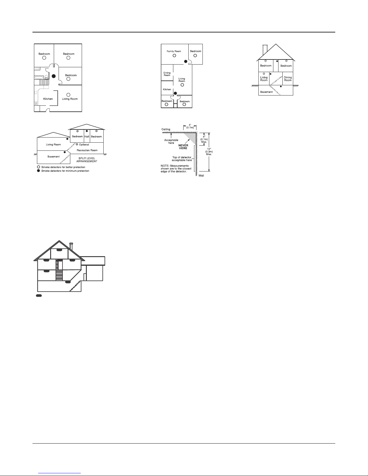
Appendix 1: Guidelines for Locating Smoke Detectors and CO Detectors
Figure 1
Figure 2
Figure 3
Figure 3a
Figure 4
GROUND
FLOOR
BASEMENT
KITCHEN
GARAGE
BEDROOM
BEDROOM
BEDROOM
CARBON MONOXIDE DETECTOR
Figure 5
Carbon Monoxide Detectors
Carbon monoxide is colorless, odorless, tasteless, and very toxic. It also moves freely in the air. CO detectors can measure
the concentration and sound a loud alarm before a potentially harmful level is reached. The human body is most vulnerable
to the effects of CO gas during sleeping hours; therefore, CO detectors should be located in or as near as possible to sleep-
ing areas of the home. For maximum protection, a CO alarm should be located outside primary sleeping areas or on each
level of your home. Figure 5 indicates the suggested locations in the home.
Do NOT place the CO alarm in the following areas:
l Where the temperature may drop below -10ºC or exceed 40ºC
l Near paint thinner fumes
l Within 5 feet (1.5m) of open flame appliances such as furnaces, stoves and fireplaces
l In exhaust streams from gas engines, vents, flues or chimneys
l Do not place in close proximity to an automobile exhaust pipe; this will damage the detector
PLEASE REFER TO THE CO DETECTOR INSTALLATION AND OPERATING INSTRUCTION SHEET FOR SAFETY
INSTRUCTIONS AND EMERGENCY INFORMATION.
Household Fire Safety Audit
Read this section for important information about fire safety. Most fires occur in the home. To minimize this danger, we
recommend that a household fire safety audit be conducted and a fire escape plan be developed.
- 49 -
Page 53

Appendix 1: Guidelines for Locating Smoke Detectors and CO Detectors
1. Are all electrical appliances and outlets in a safe condition? Check for frayed cords, overloaded lighting circuits, etc.
If you are uncertain about the condition of your electrical appliances or household service, have a professional eval-
uate these units.
2. Are all flammable liquids stored safely in closed containers in a well-ventilated cool area? Cleaning with flammable
liquids should be avoided.
3. Are fire-hazardous materials (e.g., matches) well out of reach of children?
4. Are furnaces and wood-burning appliances properly installed, clean and in good working order? Have a pro-
fessional evaluate these appliances.
Fire Escape Planning
There is often very little time between the detection of a fire and the time it becomes deadly. It is thus very important that a
family escape plan be developed and rehearsed.
1. Every family member should participate in developing the escape plan.
2. Study the possible escape routes from each location within the house. Since many fires occur at night, special atten-
tion should be given to the escape routes from sleeping quarters.
3. Escape from a bedroom must be possible without opening the interior door.
Consider the following when making your escape plans:
l Make sure that all border doors and windows are easily opened. Ensure that they are not painted shut, and that their
locking mechanisms operate smoothly.
l If opening or using the exit is too difficult for children, the elderly or handicapped, plans for rescue should be
developed. This includes making sure that those who are to perform the rescue can promptly hear the fire warning
signal.
l If the exit is above the ground level, an approved fire ladder or rope should be provided as well as training in its use.
l Exits on the ground level should be kept clear. Be sure to remove snow from exterior patio doors in winter; outdoor
furniture or equipment should not block exits.
l Each person should know the predetermined assembly point where everyone can be accounted for (e.g., across the
street or at a neighbour’s house). Once everyone is out of the building, call the fire department.
l A good plan emphasizes quick escape. Do not investigate or attempt to fight the fire, and do not gather belongings
as this can waste valuable time. Once outside, do not re-enter the house. Wait for the fire department.
l Write the fire escape plan down and rehearse it frequently so that should an emergency arise, everyone will know
what to do. Revise the plan as conditions change, such as the number of people in the home, or if there are changes
to the building’s construction.
l Make sure your fire warning system is operational by conducting weekly tests. If you are unsure about system oper-
ation, contact your installer.
l We recommend that you contact your local fire department and request further information on fire safety and escape
planning. If available, have your local fire prevention officer conduct an in-house fire safety inspection.
- 50 -
Page 54
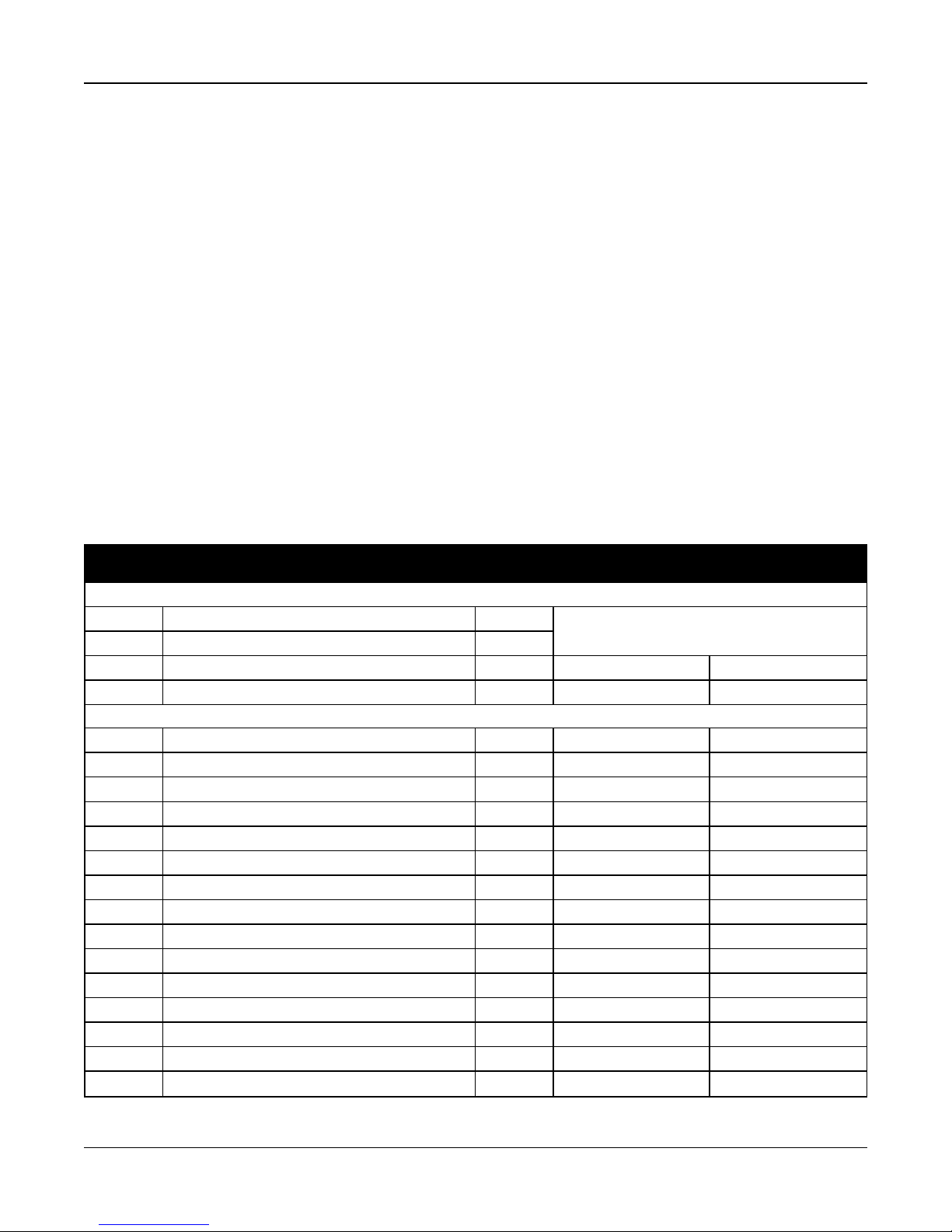
Appendix 2: Reporting Codes
Appendix 2: Reporting Codes
The following tables contain Contact ID and Automatic SIA format reporting codes.
Contact ID
Each of the digits indicate specific information about the signal. For example, if zone 1 is an entry/exit point, the event code
contains [34]. The central monitoring station would receive the following:
*BURG - ENTRY/EXIT - 1 where the “1” indicates which zone went into alarm.
See "Contact ID and SIAZone Alarm/Restore Event Codes" on page 51 for code definitions.
SIA Format - Level 2 (Hard Coded)
The SIA communication format used in this product follows the level 2 specifications of the SIA Digital Communication
Standard - October 1997. This format sends the account code along with its data transmission. The transmission appears
similar to the following at the receiver:
N ri1 BA 01
N = New Event
ri1 = Partition /Area Identifier
BA = Burglary Alarm
01 = Zone 1
A system event uses the Area Identifier ri00.
Contact ID and SIAZone Alarm/Restore Event Codes
Sec tion # Definition
Zone Events
Zone Alarms A/R
Zone Restores A/R
Zone t amper/restore MA/R E(3)83-ZZZ / R(3)83-ZZZ TA-ZZZ / TR-ZZZZ
Zone f ault/restore MA/R E(3)8A-ZZZ / R(3)8A-ZZZ UT -ZZZZ / UJ-ZZZZ
Tamper Even ts
Keypad 1 tamper/restore alarm T/R E(3)83-601/ R(3)83-601 TA-0601 / TR-0601
Keypad 2 tamper/restore alarm T/R E(3)83-602/ R(3)83-602 TA-0602 / TR-0602
Keypad 3 tamper/restore alarm T/R E(3)83-603/ R(3)83-603 TA-0603 / TR-0603
Keypad 4 tamper/restore alarm T/R E(3)83-604/ R(3)83-604 TA-0604 / TR-0604
Siren 1 tamper/restore alarm T/R E (3)83-801 / R (3)83-801 TA-0801 / TR-0801
Siren 2 tamper/restore alarm T/R E(3)83-802 / R (3)83-802 TA-0802 / TR-0802
Siren 3 tamper/restore alarm T/R E(3)83-803 / R (3)83-803 TA-0803 / TR-0803
Siren 4 tamper/restore alarm T/R E (3)83-804 / R (3)83-804 TA-0804 / TR-0804
Siren 5 tamper/restore alarm T/R E(3)83-805 / R (3)83-805 TA-0805 / TR-0805
Siren 6 tamper/restore alarm T/R E(3)83-806 / R (3)83-806 TA-0806 / TR-0806
Siren 7 tamper/restore alarm T/R E(3)83-807 / R (3)83-807 TA-0807 / TR-0807
Siren 8 tamper/restore alarm T/R E(3)83-808 / R (3)83-808 TA-0808 / TR-0808
Siren 9 tamper/restore alarm T/R E(3)83-809 / R (3)83-809 TA-0809 / TR-0809
Siren 10 t amper/restore alarm T/R E (3)83-810 / R (3)83-810 TA-0810 / TR-0810
Siren 11 t amper/restore alarm T/R E(3)83-811 / R (3)83-811 TA-0811 / TR-0811
Dialer Direction*
Automatic Contact ID
Codes
see "Contact ID & SIA Zone Alarm/Restore Event Codes" on
page 56" for details.
SIA Auto Rep Codes**
- 51 -
Page 55
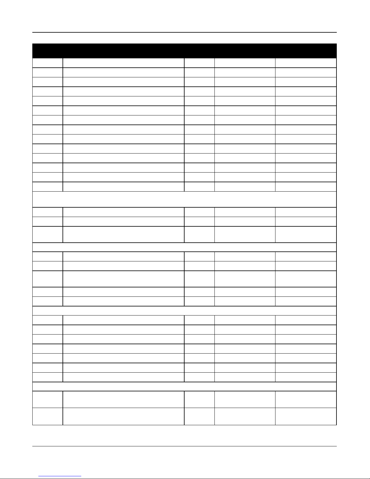
Appendix 2: Reporting Codes
Sec tion # Definition
Siren 12 t amper/restore alarm T/R E (3)83-812 / R (3)83-812 TA-0812 / TR-0812
Siren 13 t amper/restore alarm T/R E(3)83-813 / R (3)83-813 TA-0813 / TR-0813
Siren 14 t amper/restore alarm T/R E (3)83-814 / R (3)83-814 TA-0814 / TR-0814
Siren 15 t amper/restore alarm T/R E(3)83-815 / R (3)83-815 TA-0815 / TR-0815
Siren 16 t amper/restore alarm T/R E (3)83-816 / R (3)83-816 TA-0816 / TR-0816
Repeater 1 tamper/restore alarm T/R E(3)83-901 / R (3)83-901 TA-0901 / TR-0901
Repeater 2 tamper/restore alarm T/R E(3)83-902 / R (3)83-902 TA-0902 / TR-0902
Repeater 3 tamper/restore alarm T/R E(3)83-903 / R (3)83-903 TA-0903 / TR-0903
Repeater 4 tamper/restore alarm T/R E(3)83-904 / R (3)83-904 TA-0904 / TR-0904
Repeater 5 tamper/restore alarm T/R E(3)83-905 / R (3)83-905 TA-0905 / TR-0905
Repeater 6 tamper/restore alarm T/R E(3)83-906 / R (3)83-906 TA-0906 / TR-0906
Repeater 7 tamper/restore alarm T/R E(3)83-907 / R (3)83-907 TA-0907 / TR-0907
Repeater 8 tamper/restore alarm T/R E(3)83-908 / R (3)83-908 TA-0908 / TR-0908
Keypad Lockout - Incorrect access code entry T/R E(4)61-000 / R(4)61-000 JA-0000
Openin g Events
User Openings - Disarmed by user O/C E(4)A1-UUU OP-UUUU
Automatic Arming Canceled O/C E(4)64-UUU CI -0000
Special Opening - System disarmed using: keyswitch, main-
tenance c ode, DLS software, wireless key
Closing Events
User Closings - System armed by user, wireless key O/C R(4)A1-UUU CL-UUUU
Partial Closing - 1 or more zones bypassed when armed O/C E(4)56-000 CG-0000
Special Closing - System armed via: quick arm, k eyswitch,
function key, maintenance code, DLS software
Exit Fault O/C E(3)74-ZZZ EA-ZZZZ
Automatic (Schedule) Closing O/C R (4)A3-000 CA-0000
System Trouble Events
General syst em tamper/restore (while armed) MA/R E(1)37-000/ R(1)37-000 ES-0000/EJ-0000
General syst em tamper/restore (while disarmed) MA/R E(1)37-000/ R(1)37-000 ES-0000/EJ-0000
Battery trouble/restore - Main panel MA/R E(3)A2-000 / R(3)A2-000 YT-0000 / YR-0000
Battery absent t rouble/restore - Main panel MA/R E(3)11-000 / R(3)11-000 YM-0000 / YR-0000
Battery chargingtrouble/restore MA/R E(3)14-000/ R(3)14-000 YP-0000/ YQ-0000
PanelAC trouble/restore - Main panel MA/R E(3)A1-000 / R(3)A1-000 AT-0000/ AR-0000
Battery over voltage charge/restore MA/R E(3)14-000/ R(3)14-000 YP-000/YQ-000
Alternate Communicator
Alternate Communicator radio/SIM trouble/restore MA/R
Alternate CommunicatorGSM Network trouble/restore MA/R
Dialer Direction*
O/C E(4)AA-000 OP-0000
O/C R(4)AA-000 CL-0000
Automatic Contact ID
Codes
E(3)AA-001
R(3)AA-001
E(3)AA-001
R(3)AA-001
SIA Auto Rep Codes**
YX-0001 / YZ-0001
YX-0001 / YZ-0001
- 52 -
Page 56
Appendix 2: Reporting Codes
Sec tion # Definition
Alternate Communicator Ethernet trouble/restore MA/R
Alternate Communicator Receiver 1 absent/restore MA/R
Alternate Communicator Receiver 2 absent/restore MA/R
Alternate Communicator Receiver 3 absent/restore MA/R
Alternate Communicator Receiver 4 absent/restore MA/R
Alternate Communicator Receiver 1 Supervisory
trouble/restore
Alternate Communicator Receiver 2 Supervisory
trouble/restore
Alternate Communicator Receiver 3 Supervisory
trouble/restore
Alternate Communicator Receiver 4 Supervisory
trouble/restore
Alternate Communicator SMSConfig trouble/restore MA/R
Remote Programming Begin/End MA/R E(6)27-000 / E(6)28-000 LB-0000 / LS-0000
FTC trouble/restore MA/R E(3)54-RRR/ R(3)54-RRR YC-RRR/YK-RRR
Receiver not availabletrouble/restore MA/R E(3)5A-RRR/ R(3)5A-RRR YS-RRR/YK-RRR
Receiver supervisory t rouble/restore MA/R E(3)5A-RRR/ R(3)5A-RRR YS-RRR/YK-RRR
Wireless Events
Wireless Zone Low Battery trouble/restore. MA/R
Wireless Device Low Battery trouble/restore. MA/R
Wireless Zone AC trouble/restore MA/R
Wireless Device fault/restore MA/R
Wireless device supervisory trouble/restore MA/R
Wireless device force armed trouble/restore MA/R
Wireless Temperatureand Flood Probe trouble/restore MA/R
Freeze trouble/restore MA/R
Selt test trouble/restore MA/R
Dialer Direction*
MA/R E(3)5A-001/R(3)5A-001 YS-0001 / YK-0001
MA/R E(3)5A-002/R(3)5A-002 YS-0002 / YK-0002
MA/R E(3)5A-003/R(3)5A-003 YS-0003 / YK-0003
MA/R E(3)5A-004/R(3)5A-004 YS-0004 / YK-0004
Automatic Contact ID
Codes
E(3)AA-001
R(3)AA-001
E(3)5A-001
R(3)5A-001
E(3)5A-002
R(3)5A-002
E(3)5A-003
R(3)5A-003
E(3)5A-004
R(3)5A-004
E(3)AA-001
R(3)AA-001
E(3) 84-ZZZ
R(3) 84-ZZZ
E(3) 84-ZZZ
R(3) 84-ZZZ
E(3)A1-ZZZ
R(3)A1-ZZZ
E(3)8A-ZZZ
R(3)8A-ZZZ
E(3)8A-ZZZ
R(3)8A-ZZZ
E(5)7A-ZZZ
R(5)7A-ZZZ
E(3)8A-ZZZ
R(3)8A-ZZZ
E(3)8A-ZZZ
R(3)8A-ZZZ
E(3)89-ZZZ
R(3)89-ZZZ
SIA Auto Rep Codes**
YX-0001 / YZ-0001
YS-0001 / YK-0001
YS-0002 / YZ-0002
YS-0003 / YZ-0003
YS-0004 / YZ-0004
YX-0001 / YZ-0001
XT-ZZZZ / XR-ZZZZ
XT-ZZZZ / XR-ZZZZ
AT-ZZZZ / AR-ZZZZ
UT-ZZZZ / UJ-ZZZZ
UT-ZZZZ / UJ-ZZZZ
UB-ZZZZ / UU-ZZ ZZ
KT-ZZZZ / KJ-ZZZZ
ZT-ZZZZ / ZJ-ZZZ Z
YX-ZZZZ / YZ-ZZZZ
- 53 -
Page 57
Appendix 2: Reporting Codes
Sec tion # Definition
Carbon monoxide trouble/restore MA/R
Repeater 1 AC f ail/restore MA/R
Repeater 2 AC f ail/restore MA/R
Repeater 3 AC f ail/restore MA/R
Repeater 4 AC f ail/restore MA/R
Repeater 5 AC f ail/restore MA/R
Repeater 6 AC f ail/restore MA/R
Repeater 7 AC f ail/restore MA/R
Repeater 8 AC f ail/restore MA/R
RF jam t rouble/restore E(3)44-0000 XQ-0000/XH-0000
Wireless repeater 1-8 RF jam trouble/restore
Wireless keypad 1-8 trouble/restore
Wireless keypad supervisory trouble/restore
Wireless keypad 1-8 AC trouble/restore
Wireless keypad 1-8 battery trouble/restore
Wireless repeater 1-8 trouble/restore
Wireless repeater 1-8 supervisory t rouble/restore
Wireless siren 1-16 trouble/restore
Wireless siren 1-16 supervisory trouble/restore
Wireless siren 1-16 battery trouble/restore
Wireless repeater 1-8 battery restore
Miscellaneous Alarms
Duress Alarm - Code entered at keypad A/R E(1)21-000 HA-0000/ HH-0000
Opening After Alarm -Disarmed with alarm in memory A/R E(4)58-000 OR-0000
Dialer Direction*
Automatic Contact ID
Codes
E(3)8A-ZZZ
R(3)8A-ZZZ
E (3)A1-901
R (3)A1-901
E(3)A1-902
R (3)A1-902
E (3)A1-903
R (3)A1-903
E (3)A1-904
R (3)A1-904
E(3)A1-905
R (3)A1-905
E (3)A1-906
R (3)A1-906
E (3)A1-907
R (3)A1-907
E (3)A1-908
R (3)A1-908
E(3)44-901-908/ R(3)44-901-
908
E(3)8A-601-608/ R(3)8A-601-
608
E(3)8A-601-608/ R(3)8A-601-
608
E(3)A1-601-608/ R(3)A1-601-
608
E(3)84-601-608/ R(3)A1-601-
608
E(3)8A-901-908/ R(3)8A-901-
908
E(3)8A-901-908/ R(3)8A-901-
908
E(3)8A-901-916/ R(3)8A-901-
916
E(3)8A-901-916/ R(3)8A-901-
916
E(3)8A-901-916/ R(3)8A-901-
916
E(3)84-901-908/ R(3)A1-901-
908
SIA Auto Rep Codes**
UT-ZZZZ / UJ-ZZZZ
AT-0901 / AR-0901
AT-0902 / AR-0902
AT-0903 / AR-0903
AT-0904 / AR-0904
AT-0905 / AR-0905
AT-0906 / AR-0906
AT-0907 / AR-0907
AT-0908/ AR-0908
XQ-901-908/ XH-901-908
UT-601-608/ UJ-601-608
UT-601-608/ UJ-601-608
AT-601-608/ AR-601-608
XT-601-608/ XR-601-608
UT-901-908/ UJ-901-908
UT-901-908/ UJ-901-908
UT-901-908/ UJ-901-916
UT-901-908/ UJ-901-916
UT-901-908/ UJ-901-916
XT-901-908/ XR-901-908
- 54 -
Page 58
Appendix 2: Reporting Codes
Sec tion # Definition
Recent Closing - Alarm occurs within two minutes of system
arming
Burglary Verified A/R E(1)39-000 BV-0000
Burglary Not Verified A/R E(3)78-000 BG-0000
Alarm Canceled before expiry of alarm cancellation timer A/R E(4)A6-UUU OC-UUUU
Dialer Direction*
A/R E(4)59-UUU CR-UUUU
Automatic Contact ID
Codes
SIA Auto Rep Codes**
Priority Alarm and Restoral Events
[F] Key alarm/restore A/R
[A] Key alarm/restore A/R
[P] Key alarm/restore A/R
Fire alarm by wireless/ alarm restore A/R E(1)1A-0000/ R(1)1A-0000 FA-0000/FH-0000
Auxiliary alarm by wireless/ alarm restore A/R E(1)AA-0000/ R(1)AA-0000 MA-0000/MH-0000
Panic alarm by wireless/ alarm restore A/R E(1)2A-0000/ R(1)2A-0000 PA-0000/PH-0000
Fire alarm by interactive/ alarm restore A/R E(1)11A-0000/ R(1)11A-0000 FA-0000/FH-0000
Auxiliary alarm by interactive/ alarm rest ore A/R E(1)AA-0000/ R(1)AA-0000 MA-0000/MH-0000
Panic alarm by interactive/ alarm restore A/R E(1)2A-0000/ R(1)2A-0000 PA-0000/PH-0000
E(1)1A-000
R(1)1A-000
E(1)AA-000
R(1)AA-000
E(1)2A-000
R(1)2A-000
FA-0000 / FH-0000
MA-0000 / MH-0000
PA-0000 / PH-0000
Miscellaneous Clo sing
] Zone Bypass at time of arming O/C E(5)7A-ZZZ UB-ZZZZ
Zone unbypass O/C R(5)7A-ZZZ UU-ZZZZ
Testing
Walk Test Begin/End T
Periodic Test T E(6)A2-000 RP-0000 / RY-0000
Periodic Test with Trouble T E(6)A8-000 RY-0000
System Test T E(6)A1-000 RX-0000
Maintenan ce
General System trouble. An RF jam troubleoccurred MA/R E(3) AA-000 YX-0000
Fire trouble/restore MA/R
Heat trouble/restore MA/R
Cold Start - Syst em has restarted after total power loss MA/R R(3) A5-000 RR-0000
Smoke detector low s ensitivity trouble/restore MA/R E(3)93-ZZZ FT-0000/ FJ-0000
Event Buffer 75%Full MA/R E(6)22-000 JL-0000
Installer Lead In -Installer Programming has beenentered MA/R E(6)27-000 LB-0000
Installer Lead out - I nstaller Programming has beenexited MA/R E(6)28-000 LS-0000
Panelfirmware update begin/ successful MA/R
Panelfirmware update fail MA/R E(9)02-900 LU-0900
E(6)A7-UUU
R(6)A7-UUU
E(3)73-000
R(3)73-000
E(3)8A-ZZZ
R(3)8A-ZZZ
E(9)01-900
R(9)01-900
TS-UUUU/TE-UUUU
FT-0000 / FJ-0000
KT-ZZZZ / KJ-ZZZZ
LB-0900 / LS-0900
- 55 -
Page 59
Appendix 2: Reporting Codes
Sec tion # Definition
Periodic test with trouble MA/R E(6)A2-RRRR RP-RRRR
*
A/R =alarms/restores; T /R = tampers/restorers; O/C = openings/closings; MA/R = maintenance alarms/restores; T = test transmissions
Dialer Direction*
Automatic Contact ID
Codes
SIA Auto Rep Codes**
** UUU = user number. Note that for CID, enter 999 for user 1000. ZZZ/ZZZZ = zone number.
*** Zones and panic pendantsare identified, wirelesskeyscan beidentified for openings and closings.
Contact ID & SIA Zone Alarm/Restore Event Codes
(as per SIA DCS: ‘Contact ID’ 01-1999):
The table below defines the meaning of all Contact ID and SIA zone alarm/restore event codes.
Zone Definition SIA Auto Rep Codes Contact ID Auto Rep Codes
Delay 1 BA-ZZZZ / BH-ZZZZ E(1) 3A - ZZZ / R(1)3A- ZZ Z
Delay 2 BA-ZZZZ / BH-ZZZZ E(1) 3A - ZZZ / R(1)3A- ZZ Z
Instant BA-ZZZZ / BH-ZZZZ E(1) 3A- ZZZ / R(1)3A- ZZZ
Interior BA-ZZZZ / BH-ZZZZ E(1) 3A- Z ZZ / R(1)3A-ZZZ
Interior Stay/Away BA-ZZZZ / BH-ZZZZ E(1) 3A- ZZZ / R(1)3A- ZZZ
Delay Stay/Away BA-ZZZZ / BH-ZZZZ E(1) 3A- ZZZ / R(1)3A- ZZZ
Day Zone BA-ZZZZ / BH-ZZZZ E(1) 3A- Z ZZ / R(1)3A-ZZZ
24-Hr. Burglary BA-ZZZZ / BH-ZZZZ E(1) 3A- ZZZ / R(1)3A- ZZZ
Standard 24-Hr. Fire (Wireless) FA-ZZZZ / FH-ZZZZ E(1) 1A- ZZZ / R(1)1A - ZZZ
24-Hr.Low Temperature ZA-ZZZZ / ZH-ZZZZ E(1) 59 - ZZZ / R(1)59-ZZZ
24-Hr High Temperature KA-ZZZZ / KH-ZZZZ E(1) 58 - ZZ Z / R(1)58- Z ZZ
24-Hr. Non Alarm (Walk Test Only) BA-ZZZZ / BH-ZZZZ E(1) 3A -ZZZ / R(1)3A- ZZZ
24-Hr. Supervisory Buzzer UA-ZZZZ / UH-ZZ ZZ E(1) 5A- ZZZ / R(1)5A - ZZZ
24-Hr. Auto Verified Fire (Wireless) FA-ZZ ZZ / FH-ZZZZ E(1) 1A - ZZ Z / R(1)1A- Z ZZ
24-Hr. CO Alarm GA-ZZZZ / GH-ZZZZ E(1) 62- ZZZ / R(1)62 - ZZZ
24-Hr. Holdup HA-ZZZZ / HH-ZZ ZZ E(1) 22- ZZZ / R(1)22 - ZZZ
24-Hr. Panic PA-ZZZZ / PH-ZZZZ E(1) 2A - ZZZ / R(1)2A - ZZZ
24-Hr. Flood WA-ZZZZ / WH-ZZZZ E(1) 54 -ZZZ / R(1)54 - ZZZ
24-Hr. Auxiliary MA-ZZZZ / MH-ZZZZ E(1) AA - ZZZ / R(1)AA - ZZZ
Push t o Set (Walk Test Only) BA-ZZZZ / BH-ZZZZ E(1) 3A- ZZZ / R(1)3A - ZZZ
ZZZ/ZZZZ = zones 001-128
- 56 -
Page 60

Appendix 3: Regulatory Information
Appendix 3: Regulatory Information
This product has been tested and found in compliance with the following standards:
l UL1023 Household Burglar-Alarm System Units
l UL985 Household Fire Warning System Units
l ULC-S545-02 Residential Fire Warning System Control Units
l ORD-C1023-1974 Household Burglar-Alarm System Units
This product has also been tested and found in compliance with the ANSI/SIA CP-01-2014 Control Panel Standard –
Features for False Alarm Reduction.
This product is UL/ULC listed under the following categories:
l UTOU/UTOUC Control Units and Accessories, Household System Type
l NBSX/NBSXC Household Burglar Alarm System Units
l AMTB Control Panels, SIA False Alarm Reduction
The product is labeled with the UL and ULC listing marks along with the SIA CP-01 compliance statement (Also Classified
in accordance with SIA-CP-01 Standard) as proof of compliance with the above mentioned standards. For further inform-
ation on this product’s listings please also refer to the official listing guides published at the UL web site (www.ul.com)
under Certifications Section.
UL/ULC Residential Fire and Burglary Installations:
For ULC Installations refer to the Standard for the Installation of Residential Fire Warning Systems, CAN/ULC-S540.
l Use at least one PG9916 or PG9926 Smoke Detector for Fire Installations (refer to Installer portal > Panel Settings>
Zones> Add Device (Enter Device Serial # or Auto Enroll) > Type >Standard Fire)
l The entry delay shall not exceed 60 seconds (refer to Installer portal > Panel Settings>Panel Configuration>Partition
Configuration> Entry Delay 1)
l The exit delay shall not exceed 120 seconds (refer to Installer portal > Panel Settings>Panel Configuration>Partition
Configuration> Exit Delay)
l The minimum Bell Time-out is 4 minutes (refer to Installer portal > Panel Settings>Panel Configuration>System Con-
figuration> Burglary Bell Time-out)
Note: For ULC Residential Fire Installations the minimum Bell Time-out is 5 minutes
l Temporal Three Fire Signal shall be enabled (hardcoded ON)
l Arm/Disarm Bell Squawk shall be enabled when using wireless key PG9929, PG9939 or PG9949 (refer to Installer
portal > Panel Settings>Panel Configuration>System Configuration> > Local arm shall be ON)
l A code shall be required for bypassing (refer to Installer portal >Panel Settings>Panel Configuration>System Con-
figuration> Access Code Is Required for Bypassing)
l Trouble beeps shall be enabled (refer to Installer portal >Panel Settings>Panel Configuration>System Con-
figuration> Trouble Beeps Auto Silence)
Note: This product is programmed to perform 5 attempts for communication of an event to the supervising station. If unsuc-
cessful, a Fail To Communicate (FTC) trouble is generated.
l Test transmission cycle shall be set for monthly transmission (refer to Installer portal > Panel Settings>Panel Con-
figuration>Comms Configuration> Ethernet Test Transmission Cycle & Cellular Test Transmission Cycle)
l For UL installations, 2 repeaters (model PG9920) must be used for proper signal routing.
Note: For ULC Residential installations set for daily test transmission
l Wireless Supervision window shall be enabled (refer to Installer portal > Account Details > Panel Configuration > Eth-
ernet Supervision, Cellular Supervision)
- 57 -
Page 61

Appendix 3: Regulatory Information
l Wireless Supervision window shall be set to 4 hours for Fire Installations (refer to Installer portal > Panel Set-
tings>Panel Configuration>Comms Configuration > Ethernet Supervision, Cellular Supervision)
l Wireless Supervision window shall be set to 24h for Burglary Installations only (refer to Installer portal > Panel Set-
tings>Panel Configuration>Comms Configuration > Ethernet Supervision, Cellular Supervision)
l RF Jam detection shall be enabled (refer to Installer portal > Panel Settings>Panel Configuration>System Con-
figuration> RF Jam Detection and Reporting)
l Bells will be active During 2-way Audio (refer to Installer portal > Panel Settings > Panel Configuration > System Con-
figuration > Wireless Siren Control)
l New Alarms will Disconnect 2-way Audio (refer to Installer portal > Panel Settings > Panel Configuration > System
Configuration > New Alarms Disconnect 2-way Audio for 2G)
l When the 2- way audio feature is enabled(refer to Installer portal > Panel Settings > Zones > 2-Way Audio) ensure
that New alarms will not Disconnect 2-Way Audio is OFF and Wireless Siren During 2-Way Audio is ON
Programming
The notes in the programming sections describing the system configurations for UL/ULC listed installations shall be imple-
mented.
Bell Location
The alarm sounding device (bell) shall be located where it can be heard by the person operating the security system during
the daily arming and disarming cycle.
Casual Users
The installer should caution the user(s) not to give system information (e.g., codes, bypass methods, etc.) to casual users
(baby-sitters or service people).
User Information
The installer should advise the users and note in the User’s Manual:
l Service organization name and telephone number
l The programmed exit time
l The programmed entry time
l Test system weekly
Regulatory Agency Statements
FCC MODIFICATION STATEMENT
Digital Security Controls has not approved any changes or modifications to this device by the user. Any changes or modi-
fications could void the user’s authority to operate the equipment.
Digital Security Controls n’approuve aucune modification apportée à l’appareil par l’utilisateur, quelle qu’en soit la nature.
Tout changement ou modification peuvent annuler le droit d’utilisation de l’appareil par l’utilisateur.
ISED CANADA INTERFERENCE STATEMENT
This device complies with Part 15 of the FCC Rules and ISED Canada licence-exempt RSS standard(s). Operation is sub-
ject to the following two conditions: (1) this device may not cause interference, and (2) this device must accept any inter-
ference, including interference that may cause undesired operation of the device.
Le présent appareil est conforme aux CNR d'ISED Canada applicables aux appareils radio exempts de licence. L'ex-
ploitation est autorisée aux deux conditions suivantes : (1) l'appareil ne doit pas produire de brouillage, et (2) l'utilisateur
de l'appareil doit accepter tout brouillage radioélectrique subi, ême si le brouillage est susceptible d'en compromettre le
fonctionnement.
FCC CLASS B DIGITAL DEVICE NOTICE
This equipment has been tested and found to comply with the limits for a Class B digital device, pursuant to part 15 of the
FCC Rules. These limits are designed to provide reasonable protection against harmful interference in a residential
- 58 -
Page 62

Appendix 3: Regulatory Information
installation. This equipment generates uses and can radiate radio frequency energy and, if not installed and used in
accordance with the instructions, may cause harmful interference to radio communications. However, there is no guarantee
that interference will not occur in a particular installation. If this equipment does cause harmful interference to radio or tele-
vision reception, which can be determined by turning the equipment off and on, the user is encouraged to try to correct the
interference by one or more of the following measures:
- Reorient the receiving antenna.
- Increase the separation between the equipment and receiver.
- Connect the equipment into an outlet on a circuit different from that to which the receiver is connected.
- Consult the dealer or experienced radio/television technician for help.
CAN ICES-3 (B) / NMB-3 (B)
This Class B digital apparatus complies with Canadian ICES-003. Cet appareil numérique de classe B est conforme à la
norme canadienne ICES-003.
The reference to the WS900-xx throughout this manual is applicable to the following model numbers: WS900-19 and
WS900-29.
FCC ID:F5316WS90019
FCC ID:F5316WS900-29
IC: 160A-WS90019
IC: 160A-WS90029
FCC/ISED CANADA WIRELESS NOTICE
This equipment complies with FCC and ISED Canada radiation exposure limits set forth for an uncontrolled environment.
The antenna should be installed and operated with minimum distance of 20 m between the radiator and your body.
Antenna gain must be below:
Fre quency band 3G7090
GSM 850 / FDD V 2.1 dBi
PCS1900 / FDD II 3.7 dBi
Fre quency band LT7090
LTE B4 (1700 MHz) 1.5 dBi
LTE B13 (700 MHz) 2.2 dBi
This transmitter can be co-located or operating in conjunction with any other antenna or transmitter.
The reference to the Cellular Communicator xx7090 throughout this manual is applicable to the following model numbers:
3G7090 and LT7090.
FCC ID:F53163G7090
FCC ID:F5316LT7090
IC: 160A-3G7090
IC: 160A-LT7090
WARNING: To satisfy FCC RF exposure requi rements for mobil e transmittin g devices, a separation di stance of 20cm or mor e must be maintained
between the antenna of this device and persons during device op eration.
NIST Validationof encryption algorithm AES128 certificateNo. 4053
FCC/IC LABEL
The modular transmitter 3G7090 or LT7090 is labeled with its own FCC ID and IC number. When the module is installed
inside the host device WS900-19 or WS900- 29 and the FCC ID/IC of the module is not visible, the host device displays the
provided label referring to the FCC ID and IC of the enclosed module. This label is shipped together with the module and it
is the responsibility of the integrator to apply it to the exterior of the enclosure, as displayed in the following figure.
- 59 -
Page 63

SIA False Alarm Reduction Installations: Quick Reference
Caution
Fire Alarm Verification feature (Auto Verified Fire Zone) is supported on the DSC Wireless Smoke Detector, Model PGx916
and PGx926. The fire alarm delay is 40s.
Notes:
Programming at installation may be subordinate to other UL requirements for the intended application.
Cross zones have the ability to individually protect the intended area (e.g. motion detectors which overlap).
Cross zoning is not recommended for line security Installations nor is to be implemented on exit/entry zones.
There is a communication delay of 30 seconds in this control panel. It can be removed, or it can be increased up to 45
seconds at the option of the end user by consulting with the installer.
The security system shall be installed with the sounding device activated and the communicator enabled for transmission
using SIA or CID format.
SIA Feature
Programming Section
Exit Delay
Panel Settings>Panel Con-
figuration>Partition Con-
figuration> Exit Delay (select 45s,
60s, 90s, or 2 min)
Exit Time Restart (hardcoded ON) Enables the exit delay restart feature Default: Enabled Required
Auto Stay Arm on Un-vacated
Premises
Zones must be programmed as
stay/Away
Entry delay(s)
Panel Settings>Panel Con-
figuration>Partition Configuration
> Entry Delay
(select 30s, 45s, 60s, 2mins,
3mins or 4mins)
Abort Window for Non-Fire zones Transmission Delay zone attribute must
Comments Range/Default Requirement
Access to Entry and Exit delays and Bell
Time Out for the system
Function Key: Stay Arming. All Stay/Away
type zones will be automatically bypassed
Access to Entry and Exit delays and Bell
Time Out for the system
Note: Combined Entry delay and Com-
munications Delay (Abort Window) shall
not exceed 60s
be enabled
Range: 45- 120 sec.
Default: 60 sec.
If no exit after full arm
Default: Enabled
Range: 30 sec. to 4 min.
Default: 30 sees
May be disabled by zone
or zone type Default:
Enabled
Required
(programmable)
Required
Required
(programmable)
Required
Abort Window Time for Non-Fire
zones
Panel Settings>Panel Con-
figuration>System Configuration
> Communication Delay
Abort Annunciation An audible tone is generated when an
Access to the programmable delay
before communicating alarms
Note: Combined Entry delay and Com-
munications Delay (Abort Window) shall
not exceed 60s
alarm is aborted during the Abort window
- 60 -
Range: up to 45 sec.
Default: 30 sec.
Annunciate that no alarm
was transmitted Default:
Enabled
Required
(programmable)
Required
Page 64
SIA Feature
Programming Section
Comments Range/Default Requirement
Communications Canceled Win-
dow
Access to the programmable Cancel Win-
dow.
Panel Settings>Panel Con-
figuration>System Con-
figuration>Communication
Cancel Window
Cancel Annunciation
Panel Settings>Panel Con-
Access to the reporting code for Alarm
Canceled
figuration>System Configuration>
> Reporting
Duress Feature Do not derive code from an existing
Master/User code (e.g., Master code is
1234, the duress code should not be
1233 or 1235)
Cross Zone Timer
Panel Settings>Panel Con-
Access to the programmable Cross Zone
timer
figuration>Partition Configuration
>Cross Zone Delay
Range: minimum 5 min.
Default: 5 min.
Note: minimum 5 min. for
UL installations
Annunciate that a Cancel
was transmitted. Default:
Enabled
No automatic derivative of
another user code. No
duplicates with other user
codes
Default: Disabled
May program Range: 001-
255 seconds. Default: 0
seconds
Required
Required
Allowed
Allowed
Swinger Shutdown for Alarms
Panel Settings>Zones> Swinger
Shutdown
Access to the swinger shutdown limit for
zone alarms.
For all non-fire zones shut-
down at 1 or 6 trips
Default: 2 trips
24 hour auto verified Fire Access to 24 hour auto verified Fire Activates If a restore is Not
received within the spe-
cified time Default: dis-
abled
System Test:
Panel Settings> Diagnostics>
The system activates all keypad sounders, bells or sirens for 2 seconds and all keypad
lights turn on. Refer to the User Manual.
System>System Test
Panel Settings> Diagnostics>
This mode is used to test each zone on the system for proper functionality.
System> Device> Begin Walk
Test
For SIA CP-01 compliant installations, the minimum configuration is:
1) Control Panel: Model WS900-29, WS900-19
2) Annunciators for progress: Model WS900-29, WS900-19, PG9901, PG9911
3) Off Premise Transmission: Model WS900-29, WS900-19
4) Local alarm bell: WS900-29, WS900-19, PG9901, PG9911
5) Smoke Detector: Model PG9926, PG9916
6) Arming Device: Model WS900-29, WS900-19, PG9929, PG9939, PG9949
Required
(programmable)
Required
- 61 -
Page 65

Appendix 3: EULA
Appendix 3: EULA
IMPORTANT - READ CAREFULLY: DSC Software purchasedw ith or without Products and
Components is copyrightedand is purchased under the following license terms:
This End-User License Agreement(“EULA”) is alegal agreement between You (the company,
individual or entity who acquired the Software and any related Hardware) and Digital Security
Controls, adivisi on of Tyco Safety Products Canada Ltd. ( “DSC” ), the manufacturer of the integratedsecurity systems and thedeveloper of the software andany r elated products or components
(“HARDWARE”) which You acquired.
If the DSC software product(“SOFTWARE PRODUCT” or “SOFTWARE”) is i ntended to be
accompanied by HARDWARE, and is NOT accompanied by new HARDWARE, You may not
use, copy or install the SOFTWARE PRODUCT. The SOFTWARE PRODUCT includes computer software, and may includeassociated media, printed materials, and “online” or electronic
documentation.
Any software provided alongw ith the SOFTWARE PRODUCT that i s associated with aseparate
end-user licenseagreement is licensedto You under the terms of that l icenseagreement.
By installing, copying, downloading, storing, accessing or otherwise using the SOFTWARE
PRODUCT, You agreeunconditionally to be bound by the terms of this EULA, even if this EULA
is deemed to be a m odification of any previous arrangement or contract. If You do not agreeto the
terms of this EULA, DSC is unwilling to license the SOFTWARE PRODU CT toYou, and You
have no r ight to use it.
SOFTWARE PRODUCT LICENSE
The SOFTWARE PRODUCT is protected by copyright laws and international copyright treaties,
as well as other intellectual property laws and treaties. The SOFTWARE PRODUCT is licensed,
not sold.
1. GRANT OF LICENSE Th is EULA grants You the f ollowing rights:
Software Installation and Use- For each license You acquire, You may have only one copy of
theSOFTW ARE PRODUCT installed.
Storage/Network Use - The SOFTWARE PRODUCT may not be installed, accessed, displayed, run, sharedor usedconcurrently on or from different computers, includinga workstation,
terminal or other digital electronic device (“Device”). In other words, if You haveseveral workstations, You will haveto acquire a license for each workstation where the SOFTWARE will be
used.
Backup Copy - Youm ay m ake back-upcopies of the SOFTWARE PRODUCT, but You may
only have onecopy per licensei nstalled at any given time. You may use the back-up copy solely
for archival purposes. Except as expressly provided in this EULA, You may not otherwise make
copies of the SOFTWARE PRODUCT, including the printedm aterials accompanyingthe
SOFTWARE.
2. DESCRIPTION OF OTHER RIGHTS AND LIMITATIONS
Limitations on ReverseEngineering, Decompilation and Disassembly - Youm ay not
reverse engineer, decompile, or disassemble the SOFTWARE PRODUCT, except and only to
theextent that such activity is expressly permitted by applicable law notwithstanding this limitation. You may not make any changes or modifications tothe Software, w ithout the writtenpermission of an officer of DSC. You may not remove any proprietary notices, marks or labels from
theSoftware Product. You shall institute reasonable measures to ensure compliance wi th the
terms andconditions of this EULA.
Separation of Components - The SOFTWARE PRODUCT is licensed as a single product.Its
component parts may not be separatedfor use on more than one HARDW ARE unit.
Single INTEGRATED PRODUCT - If You acquired this SOFTWARE withHARDWARE, then
theSOFTW ARE PRODUCT is li censed with the HARDW ARE as asingle integrated product. In
this case, the SOFTWARE PRODUCT may only be used with the HARDW ARE as set forth i n
this EULA.
Rental - Youmay not r ent, l easeor lendthe SOFTWARE PRODUCT. You m ay not make it available to others or post it ona server or web site.
Software Product Transfer - Youm ay transfer all of Your rights under this EULA only as part of
a permanent sale or transfer of the HARDW ARE, providedYou retain no copies, You transfer all
of the SOFTWARE PRODUCT (includingall component parts, the media and printedm aterials,
any upgrades andthis EULA), andprovided the recipient agrees to the terms of this EULA. If the
SOFTWARE PRODUC T is an upgrade, any transfer must also include all prior versions of the
SOFTWARE PRODUC T.
Termination - W ithout prejudice to any other rights, D SC may terminatethis EULA if You fail to
comply with the terms and conditions of this EULA. In such event, Youm ust destroy all copies of
theSOFTW ARE PRODUCT and all of its component parts.
Trademarks - This EULA does not grant You any r ights in connection wi th any trademarks or service m arks of DSC or its suppliers.
3. COPYRIGHT
All titleand intellectual property ri ghts in andto the SOFTWARE PRODUCT (including but not
limi tedto any images, photographs, and text incorporated into the SOFTWARE PRODUCT), the
accompanying printedmaterials, andany copies of the SOFTWARE PRODUCT, are ownedby
DSC or its suppliers. You may not copy the printedm aterials accompanyingtheSOFTW ARE
PRODUCT. All title and intellectual property rights in and to the content which m ay be accessed
throughuse of the SOFTWARE PRODUCT are the property of the r espective content owner and
may be protectedby applicable copyright or other intellectual property laws and treaties. This
EULA grants Youno rights to use such content. All rights not expressly grantedunder this EULA
are reserved by DSC and its suppliers.
EXPORT RESTRICTIONS - You agreethat You will not export or re-export the SOFTWARE
PRODUCT to any country, person, or entity subject to Canadian export restrictions.
CHOICE OF LAW - This Software LicenseAgreement is governedby the laws of theProvinceof
Ontario, Canada.
ARBITRATION - All disputes arising inconnection with this Agreement shall bedeterminedby
final and binding arbitrationin accordance with the Arbitration Act, and the parties agreeto be
boundby the arbitrator’s decision. The place of arbitration shall be Toronto,Canada, and the languageof the arbitrationshall be English.
LIMITED WARRANTY
NO WARRANT Y - DSC PROVIDES THE SOFTWARE “AS IS” WITHOUT WARRANTY.
DSC DOES NOT WARRANT TH AT THE SOFTWARE WILL MEET YOUR REQUIREMENTS
OR THAT OPERATION OF THE SOFTWARE WILLBE UNINTERRUPTED OR ERRORFREE.
CHANGES IN OPERATING ENVIRONMENT - DSC shall not be responsible for problems
caused by changes in the operating characteristics of the HARDW ARE, or for problems in the
interaction of the SOFTWARE PRODUCT with non-DSC-SOFTWARE or HARDWARE
PRODUCTS.
LIMITATION OF LIABILITY; WARR ANTY REFLECTS ALLOCA TION OF RISK - IN ANY
EVENT, IF ANY STATUTE IMPLIES WARRANTIES OR CONDITIONS NOT STATED IN
THIS LICENSE AGREEMENT, D SC’S ENTIRE LIABILITY UND ER ANY PROVISION OF THIS
LICENSEAGREEMENT SHALL BE LIMITED TO THE GREATER OF THE AMOUNT
ACTUALLY PAID BY YOU TO LICENSE THE SOFTWARE PRODUCT AND FIVECANADIAN
DOLLARS ( CAD$5.00). BECAUSE SOME JURISDICTIONS DO NOT ALLOW TH E
EXCLUSION OR LIMITATION OF LIABILITYFOR CONSEQUENTIALOR INCIDENTAL
DAMAGES, THE ABOVE LIMITATION MAY NOT APPLYTO YOU.
DISCLAIMER OF WARRAN TIES - THIS W ARRANTY CONTAINS THE ENTIRE
WARRANTY AND SHALL BE IN LIEU OF ANY AND ALL OTHER WARRANTIES, WHETHER
EXPRESSED OR IMPLIED (INC LUDING ALL IMPLIED W ARRANTIES OF
MERCHANTABILITYOR FITNESS FOR A PARTICULAR PURPOSE) AND OF ALL OTHER
OBLIGATIONS OR LIABILITIES ON THE PART OF DSC. DSC MAKES NO OTHER
WARRANTIES. DSC NEITHER ASSUMES N OR AUTHORIZES ANY OTHER PERSON
PURPORTING TO ACT ON ITS BEHALF TO MOD8IFY OR TO C HANGE THIS WARRANTY,
NOR TO ASSUME FOR IT ANY OTHER W ARRANTY OR LIABILITY CONCERNING THIS
SOFTWARE PRODUC T.
EXCLUSIVE REMEDY AN D LIMITATION OF WARR ANTY - UNDER N O
CIRCUM STANCES SHALLDSC BE LIABLE FOR ANY SPECIAL, INCIDENTAL,
CONSEQUENTIAL OR INDIRECT DAMAGES BASED UPON BREACH OF WARRANTY,
BREACH OF CONTRACT, NEGLIGENCE, STRICT LIABILITY, OR ANY OTHER LEGAL
THEORY. SUCH DAMAGES INCLUDE, BUT ARE NOT LIMITED TO, LOSS OF PROFITS,
LOSS OF THE SOFTW ARE PRODUCT OR ANY ASSOCIATED EQUIPMENT, COST OF
CAPITAL, COST OF SUBSTITUTE OR REPLACEMENT EQUIPMENT, FACILITIESOR
SERVICES, DOWN TIME, PURCHASERS TIME, THE CLAIMS OF THIRD PARTIES,
INCLUDING CUSTOMERS, AND INJURY TO PROPERTY.
DSC recommends that the entire system becompletely testedon ar egular basis. However, despite frequent testing, anddue to, but not lim ited to, crim inal tampering or electrical disruption,it is
possible for this SOFTWARE PRODUCT to fail toperform as expected.
- 62 -
Page 66

Appendix 4: Limited Warranty
Appendix 4: Limited Warranty
Digital Security Controls warrants the original purchaser that for aperiod of twelve months from
thedate of purchase, the product shall befree of defects in materials and workmanshipunder normal use. During the warr anty period, Digital Security Controls shall, at i ts option, r epair or
replaceany defective product upon return of the product to its factory, at no chargefor labour and
materials. Any replacement and/or repairedparts are warranted for the r emainder of the original
warranty or ninety (90) days, whichever is longer. The original purchaser must promptly notify
Digital Security Controls in writing that there i s defect in material or workmanship, such wri tten
notice to be received in all events prior to expirationof the warranty period. There is absolutely no
warranty on software andall software products are sold as auser licenseunder the terms of the
software l icenseagreement includedw ith the product. The Customer assumes all responsibility
for the proper selection, installation, operation and maintenance of any products purchasedfrom
DSC. Custom products are only warranted to the extent that they do not function upon delivery. In
such cases, DSC can replace or credit at its option.
International Warranty
The warranty for international customers is the same as for any customer within Canada andthe
UnitedStates, with the exception that Digital Security Controls shall not be responsible for any
customs fees, taxes, or VAT that may be due.
Warranty Procedure
To obtainservice under this warranty, pleaser eturn the item(s) in question to the point of purchase. All authorized distributors and dealers havea warranty program. Anyoner eturning goods
to Digital Security Controls m ust first obtain an authorization number. Digital Security Controls
will not accept any shipment whatsoever for which prior authorization has not beenobtained.
Conditions to Void Warranty
This warranty applies only to defects in parts and workmanshiprelatingto normal use. It does not
cover:
l damage incurred in shippingor handling;
l damage causedby disaster such as fire, flood, wind, earthquake or lightning;
l damage due to causes beyond thecontrol of Digital Security Controls such as excess-
ive voltage, m echanical shock or water damage;
l damage causedby unauthorized attachment, alterations, modifications or foreign
objects;
l damage causedby peripherals (unless such peripherals were supplied by Digital
Security Controls);
l defects causedby failure to provide a suitable installation environment for the products;
l damage causedby useof the products for purposes other than those for whichit was
designed;
l damage from improper maintenance;
l damage arising outof any other abuse, mishandlingor improper application of the
products.
Items Not Covered by Warranty
In addition to the items which void the W arranty,thefollowing items shall not be covered by W arranty: (i) freightcost to the repair centre;(ii) products which are not identified wi th DSC' s product
label and lot number or serial number; (iii) products disassembled or repaired in such a manner
as to adversely affect performanceor prevent adequatei nspectionor testing to verify any warranty claim. Access cards or tags returnedfor replacement under warranty w ill be creditedor
replaced at DSC' s option. Products not covered by this warranty, or otherwise out of w arranty due
to age, m isuse, or damage shall be evaluated, and a r epair estimate shall be provided. No repair
work will be performed until a valid purchase order is receivedfrom the Customer and a R eturn
Merchandise Authorisation number (RMA) is issued by DSC's Customer Service.
Digital Security Controls’s li ability for failure to repair the product under this w arranty after areasonablenumber of attempts w ill be limi tedto a replacement of the product, as the exclusive remedy for breachof warranty. Under no ci rcumstances shall Digital Security Controls be l iable for
any special, incidental, or consequential damages based uponbreach of warr anty, breach of contract, negligence, strict liability, or any other legal theory. Such damages include, but are not limited to, loss of profits, loss of theproduct or any associated equipment, cost of capital, cost of
substituteor replacementequipment, facilities or services, down time, purchaser’s time, the
claims ofthird parties, including customers, and injury toproperty. The laws of some jurisdictions
limi t or do notallow the disclaimer of consequential damages. If the laws of such a j urisdiction
apply to any claim by or against DSC, the limitations and disclaimers containedhere shall beto
thegreatest extent permittedby law. Some states do not allow the exclusionor l imitation of incidental or consequential damages, so that the above may not apply to you.
Disclaimer of Warranties
This warranty contains the entire warr anty andshall bei n li eu of any and all other warranties,
whether expressed or implied (i ncluding all implied warranties of m erchantability or fitness for a
particular purpose) And of all other obligations or liabilities on the part of Digital Security Controls
Digital Security Controls neither assumes responsibility for, nor authorizes any other person purporting to act on its behalf tom odify or to change this warranty, nor to assume for it any other warranty or liability concerning this product.
This disclaimer of warranties and limited warranty are governed by the laws of the provinceof
Ontario, Canada.
Digital Security Controls recommends that the entire system becompletely testedon ar egular
basis. However, despitefrequent testing, and due to, but notlimitedto, criminal tampering or electrical disruption, it is possiblefor this product to fail toperform as expected.
Out of Warranty Repairs
Digital Security Controls wil l atits option repair or replace out-of-warranty products which are
returned to its factory according to the following conditions. Anyonereturning goods to Digital
Security Controls must first obtain an authorization number. Digital Security Controls will not
accept any shipment whatsoever for whichprior authorization has not been obtained.
Products which Digital Security Controls determines to be r epairable will be repaired and
returned.A set fee which Digital Security Controls has predeterminedand which may be revised
from time totim e, will bechargedfor each unit repaired.
Products which Digital Security Controls determines not to be r epairable will be replacedby the
nearest equivalent product available at that tim e. The curr entmarket price of the r eplacement
product wil l be chargedfor each replacement unit.
- 63 -
Page 67

Appendix 5: WARNING: Installer please read carefully
Appendix 5: WARNING:
Installer please read carefully
Note to Installers
The warnings on this page contain vital information. As theonly individual incontact with system
users, it is thei nstaller’s responsibility to bring each item in this warning to the attention of all
users of this system.
System Failures
This system has been carefully designed to be as effective as possible.There are cir cumstances,
however, involving fire, burglary, or other types of emergencies w here it may not provideprotection. Any alarm system of any type may be compromised deliberately or may fail tooperateas
expected for a variety of r easons. Some, butnot all, of the reasons m ay be:
Access by Intruders
Intruders may enter through an unprotected access point, ci rcumvent a sensing device,evade
detection by moving through an area of insufficient coverage, disconnect a warning device, or interfere with or prevent the proper operation of the system.
Component Failure
Although every effort has been made to make this system as reliable as possible, the system may
fail to function as intended due to the failure of acomponent.
Compromise of Radio Frequency (Wireless) Devices
Signals m ay not reach the receiver under all circumstances which could include metal objects
placed on or near the radio path or deliberate jamming or other inadvertent radio si gnal interference.
Criminal Knowledge
This system contains security features w hich were known to be effectiveat the time of m anufacture. It is possible for persons with criminal i ntent to develop techniques which r educe the
effectiveness of these features.It is important that your security system be reviewed periodically
to ensure that its features remain effectiveand that it is updatedor r eplaced if it is foundthat it
does not provide the protection expected.
Failure of Replaceable Batteries
This system’s wireless transmitters have been designed to provide several years of battery life
under normal conditions. The expectedbattery life is a function of the device environment, usage,
and type. Ambient conditions such as high humidity, highor l ow temperatures, or largetemperature fluctuations m ay r educe the expected battery life. While eachtransmitting device has a
low battery m onitor whichidentifies when the batteries needto be replaced, this monitor m ay fail
to operate as expected. Regular testingand maintenance wi ll keep the system in good operating
condition.
Inadequate Installation
A security system must be installedproperly inorder toprovide adequate protection.Every installationshould be evaluated by asecurity professional to ensure that all access points andareas are
covered. Locks and latches on w indows and doors must be secure andoperateas intended. W indows, doors, walls, ceilings and other buildingm aterials must be of sufficient strength and constructionto provide the level of protection expected. A reevaluationm ust be doneduring and after
any construction activity. An evaluation by the fire and/or police department is highly r ecommended if this service i s available.
Inadequate Testing
Most problems that would preventan alarm system from operating as intended can be found by
regular testingand maintenance. The complete system should be testedweekly and imm ediately
after abreak-in, an attempted break-in, a fir e, a storm, an earthquake, an accident, or any kind of
constructionactivity insideor outside the premises. The testing should include all sensing
devices, keypads, consoles, alarm indicating devices, andany other operational devices that are
part of the system.
Insufficient Time
There may be circumstances when the system will operateas intended, yet the occupants will not
be protectedfrom an emergency due to their inability to respond to the warnings in a timely manner. If thesystem is remotely monitored, the responsem ay not occur in time to protect theoccupants or their belongings.
Motion Detectors
Motion detectors can only detect motion within the designated areas as shown in their respective
installation instructions. They cannot discriminate betweeni ntruders and intendedoccupants.
Motion detectors do not provide volumetric area protection. They have multiple beams of detection andm otioncan only be detectedin unobstructed areas covered by these beams. They cannot
detect motion which occurs behind walls, ceilings, floor, closed doors, glass partitions,glass
doors or windows. Any type of tampering whether intentional or unintentional such as m asking,
painting, or sprayingof any material on the lenses, m irr ors, w indows or any other part of the detection system w ill impair its proper operation.
Passive infraredmotiondetectors operate by sensing changes i n temperature. However their
effectiveness can be reduced when the ambienttemperature r ises near or abovebody temperature or if there are intentional or unintentional sources of heat in or near the detection area.
Some of theseheat sources could be heaters, radiators, stoves, barbecues, fireplaces, sunlight,
steam vents, lightingand so on.
Power Failure
Control units, intrusion detectors, smokedetectors and many other security devices require an
adequate power supply for proper operation.If a device operates from batteries, it is possiblefor
thebatteries to fail. Even if the batteries have not failed,they m ust be charged, in goodcondition
and installed correctly. If a device operates only by AC power, any interruption, however brief, will
render that device inoperative while it does not havepower. Power interruptions of any length are
often accompanied by voltage fluctuations which m ay damageelectronic equipment such as a
security system. After a power interruption has occurred, immediately conduct a complete system test to ensure that the system operates as intended.
Security and Insurance
Regardless of i ts capabilities, an alarm system is not a substitute for property or life insurance.
An alarm system also is not a substitute for property owners, renters, or other occupants to act
prudently toprevent or minimize the harmful effects of an emergency situation.
Smoke Detectors
Smoke detectors that are a part of this system may not properly alert occupants of a fire for a number of reasons, some of whichfollow. The smoke detectors may havebeen improperly i nstalled
or positioned. Smoke may not be able to r eachthe smoke detectors, such as when thefire i s in a
chimney, walls or roofs, or ontheother side of closed doors. Smoke detectors m ay not detect
smoke from fires on another level of the r esidence or building.
Every fire is different in the amount of sm oke producedand the rate of burning. Smoke detectors
cannotsense all types of fires equally well. Smoke detectors m ay not provide timely warningof
fires caused by carelessness or safety hazards such as sm okingin bed, violent explosions, escaping gas, improper storage of flammable materials, overloaded electrical circuits, children playing
with m atches, or arson.
Eveni f the sm oke detector operates as intended, there may be circumstances when there i s insufficient warning to allow all occupants to escapei n tim e to avoid injury or death.
Warning Devices
Warning devices such as si rens, bells, horns, or strobes may not warn people or waken someone
sleeping if there is ani nterveningwall or door. Ifwarningdevices are locatedon a different l evel of
ther esidence or premise, then it is less likely that the occupants w ill be alertedor awakened. Audible warning devices may beinterferedwith by other noise sources such as stereos,radios,televisions, air conditioners, other appliances,or passing traffic. Audible w arningdevices, however
loud, m ay not be heard by a hearing-impaired person.
SIMPLIFIED EU DECLARATION OF
CONFORMITY
Hereby, Tyco Safety Products Canada Ltd declares that the
radio equipment type Wireless Alarm System with Integral
Cellular Alarm Communicator is in compliance with Dir-
ective 2014/53/EU.
The following models are covered by this guide: WS900-14,
WS900-24, 3G7090, LT7090 (used in North America only),
WS901-14, WS901-24EU, WS901-18, WS901-28 and
3G7090-EU.
The full text of the EU declarations of conformity for the mod-
els mentioned below are available at the following internet
addresses:
Model WS901-14: http://dsc.com/pdf/1707001
Model WS901-24EU: http://dsc.com/pdf/1707002
Model WS901-18: http://dsc.com/pdf/1707003
Model: WS901-28: http://dsc.com/pdf/1707004
Model: 3G7090-EU: http://dsc.com/pdf/1707005
- 64 -
Page 68

Appendix 5: WARNING: Installer please read carefully
Product specifications:
Frequency Bands Maximum Power
g1 433.04MHz – 434.79MHz 10mW
h1.4 868.0MHz –868.6MHz
h1.5 868.7MHz –869.2MHz
2400MHz-2483.5MHz 100mW
EGSM/EDGE: 880MHz –
915MHz
DCS/EDGE: 1710MHz –
1785MHz
FDD Band VIII: 880MHz –
915MHz
FDD Band I: 1920MHz –
1980MHz
10mW
Class 4 (2W) @ 900 MHz, E-GSM
Class E2 (0.5W) @ 900 MHz, EDGE
Class 1 (1W) @ 1800 MHz, DCS
Class E2 (0.4W) @ 1800 MHz, EDGE
Class 3 (0.25W) @ 900/1800 MHz,
FDD I/VIII
European single point of contact
Tyco Safety Products, Voltaweg 20, 6101 XK Echt, Neth-
erlands
- 65 -
Page 69

The Tyco cloud collects Data from the iotega panel (public IP address, security events and statuses, security configuration, and sys-
tem diagnostics) in order to improve system performance, troubleshoot customer issues, and improve user experience. You have the
right to access, correct and request removal of your personal data by contacting [email protected] and the right to
lodge a complaint with a supervisory authority. Tyco will not transfer this data to other parties, except for our cloud service provider in
the US, with whom we have contractual Personal Data Processing Terms and EU Standard Contractual Clauses. Tyco uses
industry-standard safeguards to protect your personal information. Find out more in our Privacy Statement at www.tyco.com/privacy.
Your personal information will be retained as long as necessary to achieve the purpose for which it was collected and for any period
thereafter as legally required or permitted by applicable law.
The trademarks, logos, and service marks displayed on this document are registered in the United States [or other countries]. Any
misuse of the trademarks is strictly prohibited and Tyco will aggressively enforce its intellectual property rights to the fullest extent of
the law, including pursuit of criminal prosecution wherever necessary. All trademarks not owned by Tyco are the property of their
respective owners, and are used with permission or allowed under applicable laws.
Product offerings and specifications are subject to change without notice. Actual products may vary from photos. Not all products
include all features. Availability varies by region; contact your sales representative.
© 2017 Tyco Security Products
All Rights Reserved.
Tech Support: 1-800-387-3630 (Canada & U.S.)
or 905-760-3000
www.dsc.com
 Loading...