

DSC WS4965 Installation Instructions Manual
Installation Instructions
The WS4965 is a 3-zone device. The primary zone can be configured as a traditional normally closed door/window contact with supplied magnet. If
mounting the device/magnet combination is inconvenient, it can be configured for normally closed tilt switch operation for overhead doors. The WS4965 also
has 2 normally closed contact inputs.
Specifications
• Dimensions: 75mmx43mmx25mm (2 15/16" x 1 11/16" x 1") • Operating Frequency: 433MHz
• Operating Temperature: -10 to 49ºC (14 to 120ºF) • Battery: Panasonic CR123A Lithium
• Operating Humidity: 5-93% RH • Battery Life: 5-8 years (Not tested by UL/ULC.)
• UL/ULC Listed for residential use only
Compatible with PC5132-433, PC4164-433, NT9005-433, RF5501-433, RF5108-433.
Installation
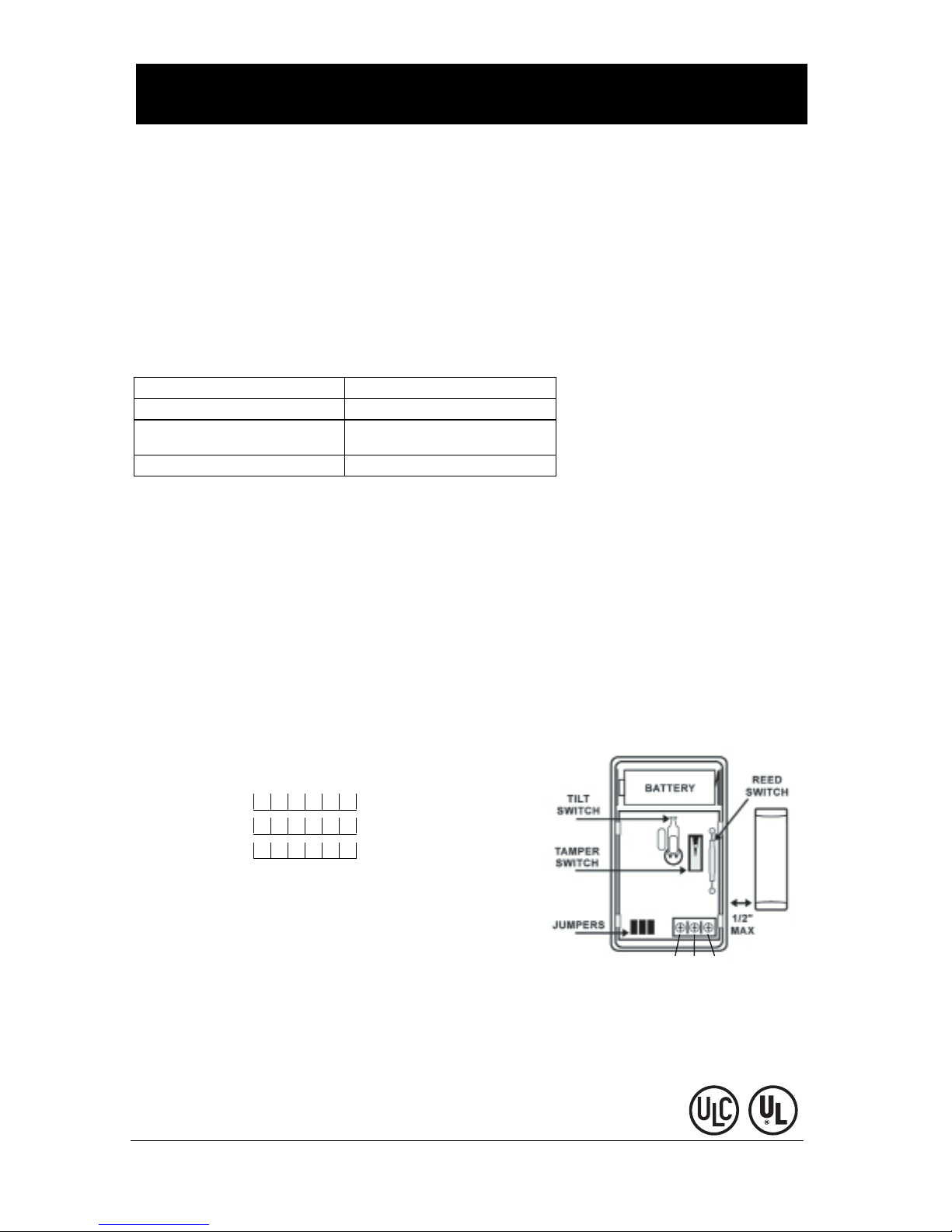
1. Select Operating Mode: Remove the cover by pressing on the end notch to lift top cover. Ensure that the jumpers 1, 2 and 3 are as follows:
Reed Switch mode Tilt Switch mode
JP1 - IN (JP1 must always be IN) JP1 - IN (JP1 must always be IN)
JP2 - NA (No effect in Reed Switch operating mode) JP2 - IN (No delay)
JP3 - IN JP3 - OUT
2. Install Battery: Use care when installing the battery and observe the correct polarity (see Figure A). Use only the Panasonic CR123A lithium battery.
3. Position Transmitter: Select the location where the WS4965 is to be mounted.
Note: RF signals can be affected by metal objects, including metal doors or large mirrors. Ensure that these types of objects are not located between
the device and the receiver as it can interfere with the proper operation of the WS4965.
4. Enrolling, Programming and Placement: The three zones of the WS4965 have unique serial numbers. The 6 digit serial number located on
the device is for the reed or tilt switch zone. The serial numbers for the second and third zone (i.e. external contacts inputs) is the serial number located on
WS4965 + 1 for Zone 2 and the serial number +2 for Zone 3 as indicated below.
Example: Serial number printed on the WS4965 is 211117.
Reed or Tilt switch zone - 211117
Zone 2 - 211118
Zone 3 - 211119
If the last digit is a letter, use the following sequence: A, B, C, D, E, F (A+1=B, A+2=C etc.)
The following steps outline the basic programming and enrollment of this device when used with PowerSeries receivers. For additional options, or for
other receivers, refer to the specific receiver Installation Manual.
Step 1: Program Electronic Serial Number (ESN) - Section [804], subsections [01] - [32]
[01] Zone 1 ... [32] Zone 32
Enter the 6 digit ESN located on the back of the device into the next available zone slot.
For Example ESN: 211117
[01] Zone #1 211117(Reed/Tilt zone)
[02] Zone #2 211118(External contact zone)
[03] Zone #3 211119(External contact zone)
Step 2: Program Zone Definition - Section [001] - [004]
Define corresponding zone with appropriate zone type [Ex. Delay (01), Instant (03), etc.]
Step 3: Enable Wireless Zone Attribute - Section [101] - [132]
Turn Option [8] ON (wireless zone attribute) in the corresponding zone attribute section
All wireless devices must be tested for good signal strength from where they are
positioned.
Note: Test wireless device signal strength from the final mounting position.
Step 4: Module Placement Test - Section [904], subsections [01] - [32]
Create a transmission by moving the magnet away from the WS4965, or by activating
the tilt sensor.
The panel will sound the siren and light LED 1 or 3 to indicate the test result:
1 squawk of the siren (or keypad LED 1) indicates GOOD placement
3 squawks of the siren (or keypad LED 3) indicates BAD placement
If the transmitter tests BAD, move the transmitter and repeat the Placement Test until 3 GOOD results in a row are indicated.
JP2 - OUT (1 minute delay before sending an alarm)
+
JP3 JP2 JP1
Figure A
-
Z2 COM Z3
Z1
MAGNETIC
MAGNETMAGNET
(1.27 CM)
WS4965
TriZone Door/Window Contact Version 1.0
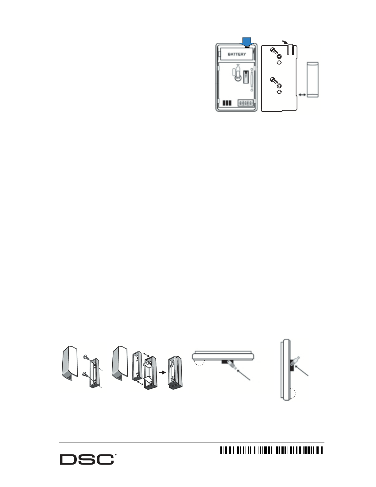
5. Mounting the WS4965
WS4965
Mounting the WS4965 in Reed Switch Mode
• Place the mounting bracket in the position determined in the Enrolling, Pro-
Push the tab
with screwdriver
Tab
gramming Placement step. Secure the bracket to the door frame using the two
screws provided. See Figure B.
• “Snap” the sensor in place.
• To release bracket: Remove the front cover. Push the tab (see Figure B) with a
small screwdriver and slide the WS4965 down.
MAGNETMAGNET
• Align one end of the magnet with the notch on the side of WS4965 housing.
See Figure A.
• Mount the magnet a maximum of 1/2" (1.27cm) from the WS4965 using
the screws provided. If necessary use the spacers provided. See Figure C.
• Mount magnet: Open and close the door/window to ensure that there is no
interference.
Note: Only one magnet can be used for each WS4965. The contact shall
Mounting Bracket
Figure B
(1.27 CM)
1/2” (1.27 CM)
MAX
be installed so that a door or window cannot be opened more than 2
inches (51 mm) without causing an alarm condition.
Mounting the WS4965 in Tilt Switch Mode
Remove Jumper 3 (JP3) for “tilt switch” operation.
For the tilt switch to be in the closed position, mount the WS4965 in the vertical position, with the battery located on the bottom. Once the garage
door is open, the tilt switch will activate and generate a transmission. See Figure D.
The WS4965 can be programmed to wait 1 minute after the tilt switch activates before it transmits the alarm. This is useful for the garage doors
which require longer entry delay time. To program this feature, remove Jumper 2 (JP2).
Notes: The reed switch is deactivated when using the tilt function.
By carefully moving the tilt switch up or down, the degree of motion required to cause an alarm can be adjusted.
Do not permanently mount the WS4965 until the Placement Test has been successfully passed.
Note: This mode is not to be used in UL listed installations.
6. External Contacts: The WS4965 has 2 normally closed contact terminals. These can be used for additional hardwired wired contacts or other dry con-
tact switches. Connect the external devices to the contact terminals as per the manufacturers instructions. The maximum wire run from the external contacts must not exceed 25ft (7.6m).
Note:For UL Installation, the external contacts and WS4965 must be in the same room.
7. Test in g: Verify Sensor operation, Tamper operation and Supervisory Operation. Operation of these features is explained below.
WS4965 Operation:
• Tamper Switch: The WS4965 comes equipped with case tamper detection. If the cover is removed, the WS4965 will report a zone tamper to the
control panel. Upon tamper, all 3 serial numbers will report a tamper transmission.
• Supervision: The WS4965 sends a periodic supervisory transmission to the panel. If the panel fails to receive a transmission within the preprogrammed period (refer to receiver manual for supervisory window), it will indicate a fault on the keypad. All three serial numbers will transmit a
separate supervisory signal to the receiver.
• Low-Battery LED Indicator: There is a low-battery LED indicator on the WS4965. It will flash at 10 second intervals when a low battery con-
dition is detected and transmitted to panel. This will provide visual identification of the unit that requires a battery change.
• Battery Replacement: The WS4965 requires one CR123A lithium battery. To replace the battery, remove the cover by pressing on the end and
lifting it up. Use care when installing the battery and observe the correct polarity. Dispose of used battery promptly. Keep away from children. Do
not disassemble and do not dispose of in fire.
Caution: The battery used in this device may present a fire or chemical burn hazard if mistreated. Do not recharge, disassemble, heat above
100°C (212°F) or dispose of in fire. Replace battery with Panasonic CR123A only. Use of another battery may present a risk of fire or explosion.
WARNING!: Battery may explode if mistreated. Do not recharge, disassemble or dispose of in fire.
Shown with NO Spacer Shown WITH Spacer
Figure C Figure D
FCC ID: F5305WS4965
This device complies with Part 15 of the FCC rules. Operation is subject to the following conditions: (1) This device must not cause harmful
interference, and (2) must accept any interference received, including interference that may cause undesired operation.
IC: 160A-WS4965 - The term “IC:” before the rad io cer tification number on ly signifies th at Industry Canada technical specifications were met.
©2005 Digital Security Controls
Toronto, Canada • www.dsc.com
Technical Support:
1-800-387-3630 (Canada & US), 905-760-3036 Printed in Taiwan
TILT SWITCH
TILT SWITCH
NOT MAKING
CONTACT
(Open)
Alarm Restore
MAKING
CONTACT
(Normally Closed)
29007111R002
 Loading...