

DSC WS4920 v1.0 Installation Instructions Manual
WS4920 v1.0
Installation Instructions, Instructions d’installation, Instrucciones de
Instalación, Instruções de Instalação, Istruzioni di installazione
NOTE: Use these instructions in conjunction with the installation manual of the alarm panel with which this
equipment is intended to be used.
WARNING: READ and SAVE These Instructions! Follow All WARNINGS AND INSTRUCTIONS specified
within this document and/or on the equipment.

SAFETY INSTRUCTIONS for WS4920 WIRELESS REPEATER
IMPORTANT:
This equipment, WS4920 WIRELESS REPEATER 1.0, shall be installed and used within an
environment that provides the pollution degree max 2 and overvoltages category II NON
HAZARDOUS LOCATIONS, indoor only. The equipment is FIXED and DIRECT PLUG IN powered
from the mains; it is designed to be installed by Service Persons only; Service Person is defined as a
person having the appropriate technical training and experience necessary to be aware of hazards to
which that person may be exposed in performing a task and of measures to minimize the risks to that
person or other persons.
1. The equipment is installed in a FIRE ENCLOSURE.
2. If during the installation a knockout is removed, it is the installer's responsibility to ensure that
the same degree of protection for the enclosure is provided by the use of bushings, fittings, etc.
3. The enclosure must be secured to the building structure before operation.
4. Internal wiring must be routed in a manner that prevents:
• Excessive strain on wire and on terminal connections
• Loosening of terminal and connections
• Damage of conductor insulation
5. The end-user and/or installer are responsible for ensuring that the disposal of the used batteries
(battery pack) is made according to the waste recovery and recycling regulations applicable to
the intended market.
WARNING: When using equipment connected to the MAINS, always follow basic safety instructions.
Refer to the SAFETY INSTRUCTIONS provided with this product; save them for (future) reference.
Instruct the end-user regarding the safety precautions that shall be observed when operating this equipment.
SAFETY precautions required during installation:
• NEVER install this equipment during a lightning storm!
• NEVER touch uninsulated wires or terminals unless the direct plug in transformer has been disconnected.
• Ensure that cables are positioned so that accidents cannot occur. Connected cables must NOT be
subject to excessive mechanical strain.
• Use only the power supply provided with this equipment. Use of unauthorized power supplies
may damage the WS4920.
• The AC socket/outlet powering the equipment shall be located near the equipment and shall be
easily accessible.
• Do NOT locate this product where persons will walk on the secondary circuit cable(s).
• Do NOT use extension cords to plug in the power supply of this equipment.
• AVOID setting up the equipment near heaters, air conditioners, ventilators, and/or refrigerators
• Do NOT connect to electrical outlets on the same circuit as large appliances.
• Do NOT select a place exposed to direct sunlight, excessive heat, moisture, vapors, chemicals or
dust.
• Do NOT install this Equipment near water. (e.g., bath tub, wash bowl, kitchen/laundry sink, in a
wet basement, or near swimming pool, etc.).
• Do NOT install this equipment and its accessories in areas where there is a risk of explosion.
• Do NOT connect this equipment to electrical outlets controlled by wall switches or automatic
timers; avoid interference sources.
WA RN I N G:
THIS EQUIPMENT HAS NO MAINS ON/OFF SWITCH. THE PLUG OF THE DIRECT PLUG-IN POWER
SUPPLY IS INTENDED TO SERVE AS THE DISCONNECTING DEVICE IF THE EQUIPMENT MUST
BE QUICKLY DISCONNECTED. IT IS IMPERATIVE THAT ACCESS TO THE MAINS PLUG AND
ASSOCIATED MAINS SOCKET/OUTLET IS NEVER OBSTRUCTED.

Table of Contents/ Table des matières/ Índice/ Indice dei contenuti
Installation Instructions.............................................................................................2
Instructions d’installation ....................................................................................... 10
Instrucciones de Instalación....................................................................................22
Instruções de Instalação ..........................................................................................34
Istruzioni di installazione ........................................................................................46
The WS4920 is compatible with the following DSC wireless devices:
Door/ Window Contact Alarm Panel Wireless Receiver
UL
WS4945
UL
WS4965
WS4975W*
EV-DW4975**
EV-DW4917
WS4925
EV-DW4955
UL
PC1616/PC1832/PC1864
UL
SCW9045-433
UL
SCW9047-433
UL
PC9155-433
UL
PC4020-433
PC4010-433
UL
RF5132-433
UL
RFK5500-433
UL
RFK5501-433
UL
RFK5508-433
UL
RFK5516-433
UL
RF4164-433
PC5132-433
RF5108-433
RF5501-433
Motion Detector Wireless Key Smoke Detector
UL
WLS914-433
UL
WS4904(P)
WS4904M
UL
WS4939
WS4949
WS4959
WS4969
WS4979
***
***
UL
WS4916
UL
WS4926
Glassbreak Detector CO Detector Hold-Up Alarm
UL
WLS912L-433
***WS4913 WLS928-433
Shock Sensor Flood Sensor Panic Pendant
UL
EV-DW4927 WS4985
UL
Only these UL/ULC listed devices are to be used with UL/ULC listed systems.
* Not available in North America, South America and New Zealand.
** Available in North America, South America and New Zealand only.
*** For Residential Fire installations, two WS4920’s must be used.
WS4938
WS4938-2W
NOTE: WS4920 is not compatible with 2-way devices.

Specifications
AWG Feet Meters
24* 5.8 1.8
22 9.3 2.8
20 14.8 4.5
18 23.5 7.2
* Not to be used for UL
listed Installations
• Temperature range: -10°C to +55°C (14°F-131°F)
Note: UL/ULC tested for 0°C to +49°C (32°F to
122°F), 85%R.H.
• Humidity (Max): 5% - 93% R.H. non-condensing
• Battery type: Rechargeable Ni-MH, 4.8V/2.1 AH
(UL Listed as an LPS. Replace battery every 3-5
years)
• Battery backup time: 24 hours
• Battery charging rate: 80% within 24 hours
• Battery charging current: 170mA
Transformer requirements:
Plug-In Class II power limited transformer (fused)
Primary: 120VAC, 60Hz, 0.2A (UL/ULC listed installations)
Secondary: 16VAC-18VAC, 20VA
The following plug-in transformers shall be used:
USA: PTD1620U, UL, CC5, efficiency level IV, 16.5V, 20VA
(UL listed installations)
Canada: PTD1620N, C-UL certified, 16.5V 20VA (ULC listed installations)
Europe: PTD1620T-EU, CE approved 230V/16.5V 20VA
Maximum allowed wire run distances:
230VAC, 50Hz, 0.1A (International Market. Acceptable to the local authorities)
• Operating frequency: 433.92 MHz
• Dimensions: H6.96, W4.47, D1.33 in.
(H17.68, W11.35, D3.38 cm)
• Weight: .77 lb. (.35kg)
1
Introduction
Green Yellow
Red
XX
The WS4920 is a wireless repeater designed to extend the range of DSC one-way wireless
transmitters and to improve signal quality between the transmitter and receiver. Use the
WS4920 to remedy transmission problems caused by excessive noise or other interference, or
by long distances between devices and receivers. The maximum recommended number of
WS4920’s per alarm system is 4.
Each enrolled WS4920 occupies a zone slot. The WS4920 does not increase the number of
supported wireless zones. This is determined by the control panel’s wireless receiver. Only zones
requiring repeat functionality need to be enrolled on the WS4920. Ensure these zones are enrolled on
both the WS4920 and the receiver/control panel.
Unpacking
Ensure your package includes the following:
• One WS4920 (rechargeable Ni-MH battery included)
• One direct plug-in transformer (Not included in all configurations)
• Mounting hardware pack, including plastic wall plugs and screws
• Installation instructions
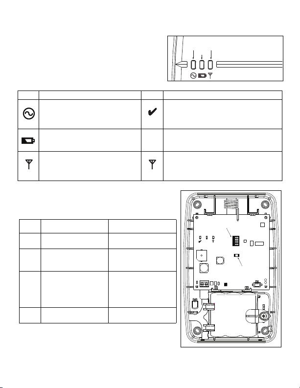
Controls and Indicators
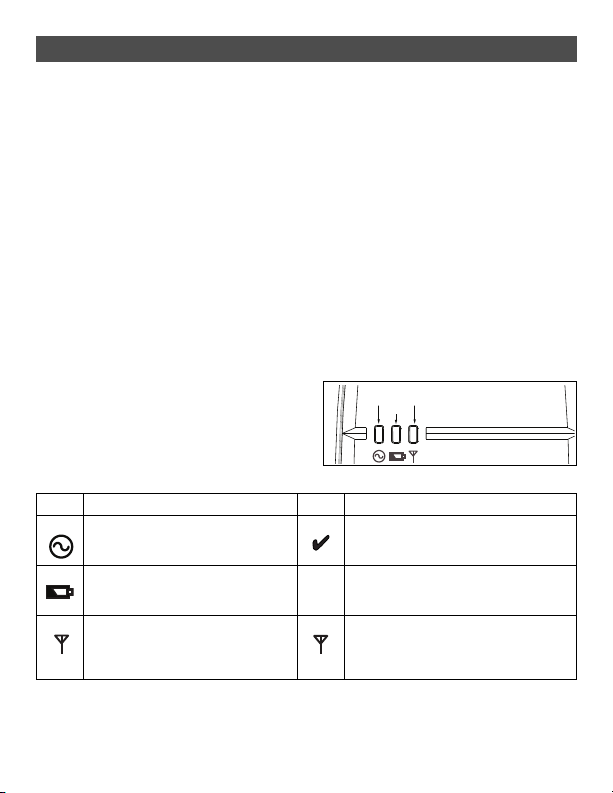
The WS4920 has three LEDs on the front. The
meaning of these LEDs is different when in
normal operational mode (cover on) than when
in Installer mode (cover off). See the table
below for descriptions of LED functionality.
The wall tamper must be closed for the LEDs
to operate.
Table 1: LED Definitions
LED Normal Mode (cover on) LED Installer Mode (cover off)
Green On: AC present
Flashing: No AC, battery good
Off: No AC and dead battery
Red On: Battery not connected
Off: Battery good (if AC on)
Flashing: Low battery
Yellow On: RF jam present
Off: No RF jam
Figure 1: LED Indicators
Green 1 flash: Enrolled
Flashing: Placement test active
Red Flashing: Zone not enrolled
Yellow On: Repeater placement test “bad”
Off: Repeater placement test “good”
Flashing: Sporadic interference or valid
transmission packets detected
2
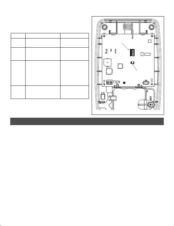
The WS4920 includes a Programming button
Table 2: DIP Switch Settings
Switch ON OFF
1 Wall tamper enabled Wall tamper
disabled
2 RF Jam notification
not sent to receiver
RF Jam
notification sent
to receiver*
3 Compatible with
RF4164, RF5108,
RF5132, RFK55xx,
SCW 9045/47, and
ALEXOR PC9155
receivers
Compatible with
future receivers
4 For installations
with 1 WS4920
For installations
with Multiple
WS4920’s
Programming
Button
X
DIP Switch
used to place it into Enroll/Placement modes.
A 4-position DIP switch is also provided to set
the following options:
The default for all switches is ON.
* RF Jam notification required for UL
Residential Fire operation.
Figure 2: Internal Controls
Installation
Install the WS4920 in the following order.
NOTE: When enrolling and placement testing the WS4920 with the alarm panel, refer to the
compatible control panel installation instructions for the appropriate programming sections.
Step 1: Temporarily Mounting the WS4920
Select a suitable location for the WS4920. Use the following list as a guide:
• Locate device near a power outlet
• Location should be free from vibration and shock
• Mount on a flat, stable surface
• Ideal location is mid-way between the wireless transmitter and receiver. The minimum distance
between the WS4920 and the receiver should be no less than 1 meter (3.28 feet)
Do not permanently mount the WS4920 until it has been placement tested. Temporarily
mount the unit using tape or other non-permanent, non-marking method. If the selected
location fails the placement test, the device must be repositioned.
Step 2: Connecting Power
Connect back-up battery first then AC.
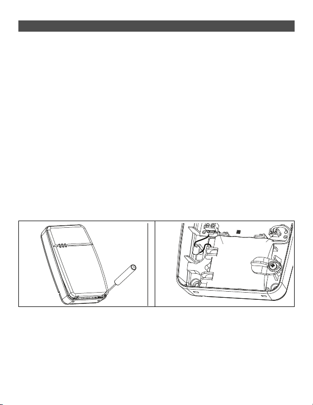
To connect the battery:
1. Gently open front cover using small slotted screwdriver in holes provided (see Figure 3).
3
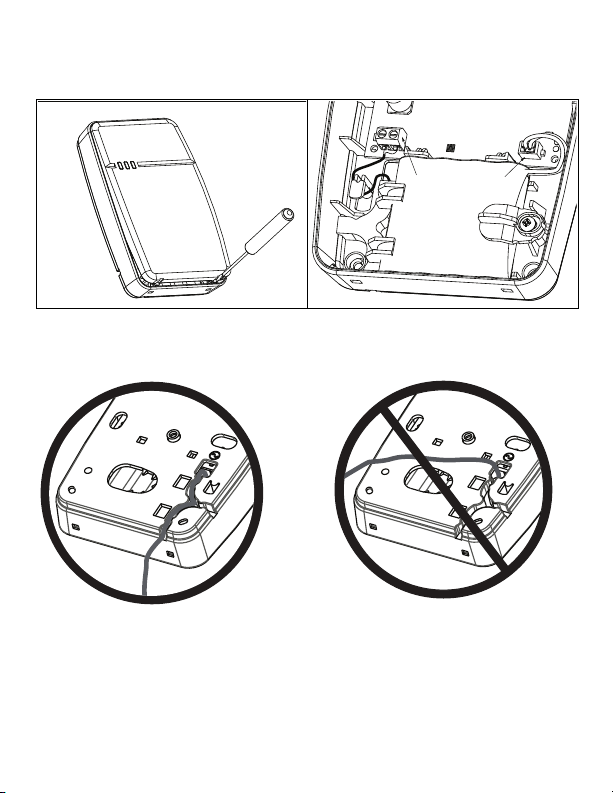
2. Attach battery cable to connector on PC board.
AC
Terminals
Battery
Connector
Depending on the charge state of the battery, a low battery trouble condition may be registered
on initial power up. The trouble may take several hours to clear.
Figure 3: Removing the Cover Figure 4: Power Connections
To connect the AC adaptor:
1. Run AC wire through channel on back of WS4920 and pass through hole in enclosure.
Figure 5: Wire Routing
2. Connect AC wires to terminals on PC board (see Figure 4).
3. Route wire around retaining bracket to secure.
4. Plug AC adaptor into wall outlet.
4

Step 3: WS4920 Repeater Placement Testing (Interference
Detection)
Repeater placement test ensures the WS4920 is located in an area with low noise and
interference and can successfully receive signals from one-way wireless devices.
To perform a Repeater placement test:
1. Press and hold Programming button for 1 second to enter Programming mode. The “Mode
Entered” tone sounds (1 long beep). Repeater placement test is continuously active until
Programming mode is exited, times out after 4 hours or cover is put back on unit.
2. If RF traffic level or noise floor level is too high, the yellow LED lights steadily. If this occurs,
reposition unit until yellow LED turns off.
3. To exit Enroll/Placement mode, press Programming button again for 1 second or place cover
back on WS4920. The “Mode Exited” (3 beeps) tone sounds.
Step 4: Enrolling the WS4920 with the Alarm Panel
The WS4920 has a six-digit electronic serial number (ESN) that must be input to the alarm
panel during enrollment.
To quick enroll the WS4920 (available on selected alarm panels):
1. Enter Wireless Enrollment mode on alarm panel (see panel installation instructions).
2. Tamper WS4920 to transmit ESN.
3. Confirm ESN on alarm panel. Panel prompts for zone number.
4. Select and accept zone number for WS4920 to complete enrollment.
To manually enroll WS4920, consult alarm panel installation manual.
NOTE: For PowerSeries, Alexor, MAXSYS and SCW9045/47, use the serial number beginning with
“2.” The serial number beginning with “A” is for future use.
NOTE: (For non-UL listed installations) Non-alarm zone type 26 is recommended. With this zone
type, loss of AC or a low battery condition are not reported to the central station. The alarm panel does
not show a trouble for the zone but will indicate it as open. Select the Force Arm attribute for this
zone. Program a zone label to identify the WS4920. e.g.,“Rpter 1 Pwr Trbl.”
NOTE: (For UL listed installations) If AC loss and low battery must be reported to the central station,
use a 24-hour zone type. Ensure the Audible attribute is set to silent.
Step 5: Placement Testing the WS4920
For optimal performance between the WS4920 and the alarm panel, the RF signal between the
two units should be as free from interference as possible.
To test the RF link between the WS4920 and the alarm panel:
1. Place alarm panel into placement test (see panel installation instructions) and select zone
where WS4920 is enrolled.
2. Tamper the WS4920.
• If alarm panel receives a strong signal, panel siren squawks once and “Location is Good” is displayed on alarm keypad.
• If alarm panel receives a weak signal, panel siren squawks three times and “Location is Bad” is
displayed on alarm keypad.
3. If alarm system indicates a weak signal or no response, check panel programming or reposition
WS4920 and repeat test. WS4920 should only be placed in location where multiple good results
are received.
5

Step 6: Quick Enroll/Placement Testing Devices
Up to 164 1-way wireless devices can be enrolled on the WS4920. During the first 4 hours of power
up, the WS4920 can be placed into Enroll/Placement Test modes. After the 4 hour time-out, access
to these modes is denied and the unit must be powered up again to enter Enroll/Placement mode.
NOTE: DLS cannot be used to enroll wireless devices on the WS4920. All wireless devices being
enrolled on the WS4920 must also be enrolled on the receiver/control panel.
To both enroll and placement test a device at the same time:
1. Press and hold Programming button for 1 second. “Mode Entered” tone (1 long beep) sounds.
The WS4920 is now in Enroll/Programming mode.
2. Trip and restore zone to be enrolled 3 times:
• Door and window contact - open/close or tamper/restore
• PIR and other stationary devices - tamper/restore
• Panic pendant - 3 to 4 button presses
• Wireless key - 3 separate button presses
3. Red LED (X) flashes until zone is enrolled. Once WS4920 has received signal from zone, Green
LED ( ) lights for 1 second and sounder emits “Zone Enrolled” (low to high) tone.
NOTE:
• If another zone is tripped during the enroll sequence, the enroll process must be restarted by tripping and restoring the appropriate zone 3 times.
• A WS4920 can not enroll another WS4920.
• Stationary (permanently mounted) devices should only be enrolled with one WS4920. The
only exception is in (UL/ULC) Residential Fire installations, where smoke and CO detectors that
are enrolled with a WS4920 must be enrolled with at least two WS4920’s.
• Fobs and panic pendants may be enrolled with multiple WS4920’s.
• If an enrollment is attempted after all 164 device slots have been filled, the WS4920 emits a 2second error tone and all three LEDs light for 20 seconds to indicate that no further devices may
be enrolled.
4. After zone is enrolled, trip again to perform placement test (to test the signal between the
wireless device and the WS4920). Green LED flashes if signal is received.
• If “Good Zone Placement” tone (1 beep) sounds, device location is satisfactory and unit may be
permanently mounted.
• If “Bad Zone Placement” tone (3 loud beeps) sounds, reposition device and trip zone again. Continue until “Good Zone Placement” (1 beep) tone sounds.
5. Repeat steps 2-4 to enroll and placement test other zones.
• To exit, press Programming button again for 1 second or place cover back on WS4920. “Mode
Exited” (3 beeps) tone sounds.
NOTE: If the WS4920 tone can not be heard while testing the device, set the alarm panel into
individual placement test mode using the WS4920 serial number. The WS4920 placement test
results are sounded through the alarm panel siren.
• Although good results may be obtained on the WS4920, bad results are still possible from the
alarm panel due to collisions.
• Subsequent violations from an enrolled zone while the WS4920 is in programming mode will
initiate a placement test.
6

Global Placement Testing Devices
Conduct placement testing with doors and windows both open and closed to ensure acceptable
placement. To placement test a 1-way wireless device after the initial Enroll/Placement test process:
1. Place the alarm panel into individual placement test mode for the WS4920 zone (see control
panel installation instructions).
2. Press and hold Programming button for 1 second. “Mode Entered” tone (1 long beep) sounds.
WS4920 is now in global placement test mode. Each zone enrolled on WS4920 gives placement
test result when tripped.
• If “Good Zone Placement” tone (1 beep) sounds, device location is satisfactory and unit may be
permanently mounted.
• If “Bad Zone Placement” (3 loud beeps) tone sounds, reposition device and trip zone again.
Continue until “Good Zone Placement” tone (1 beep) sounds.
3. To exit, press Programming button again for 1 second or place cover back on the WS4920.
“Mode Exited” (3 beeps) tone sounds.
Step 7: Mounting the WS4920
Permanently mount the WS4920 only after completing multiple successful placement tests.
To mount the WS4920:
1. Ensure AC wire is run through channel on back of WS4920.
2. Remove front cover and secure unit to wall through mounting holes using all 4 wall plugs and
screws provided.
3. Place cover back on WS4920.
4. Plug AC adaptor into unswitched AC outlet.
Restoring the WS4920 to Factory Defaults
To restore factory default settings:
1. Within 1 minute of power up, press and hold Programming button for 10 seconds. Sounder
beeps after first second to indicate WS4920 is in Installer mode. After 10 seconds, WS4920
emits double long tone and all LEDs light.
2. Release Programming button and immediately press and hold again for 10 seconds. After 10
seconds, WS4920 emits a 4-second tone and all three LEDs flash.
NOTE: The second button press must occur within 20 seconds of the first or the WS4920 will exit
Enroll/Placement mode.
3. WS4920 beeps three times and LEDs return to normal state, indicating Installer mode exit. If
Installer mode exits before reset is complete, due either to time-out or tamper, repeat procedure.
Replacing the Battery
Replace the backup battery when it no longer holds its charge.
To replace the battery:
1. Disconnect WS4920 from AC.
2. Remove front cover from device.
3. Disconnect battery cable from connector.
4. Loosen screw on battery retention bracket and rotate aside.
5. Lift battery out of holder and insert new one.
6. Reposition retention arm and tighten screw.
7. Attach battery cable to connector on PC board.
8. Snap front cover back into place.
9. Re-connect WS4920 to AC.
7

Limited Warranty
Digital Security Controls warrants that for a period of 12 months from the date of purchase, the product shall be free of defects in materials and workmanship
under normal use and that in fulfilment of any breach of such warranty, Digital Security Controls shall, at its option, repair or replace the defective equipment upon
return of the equipment to its repair depot. This warranty applies only to defects in parts and workmanship and not to damage incurred in shipping or handling, or
damage due to causes beyond the control of Digital Security Controls such as lightning, excessive voltage, mechanical shock, water damage, or damage arising
out of abuse, alteration or improper application of the equipment. The foregoing warranty shall apply only to the original buyer, and is and shall be in lieu of any
and all other warranties, whether expressed or implied and of all other obligations or liabilities on the part of Digital Security Controls. Digital Security Controls
neither assumes responsibility for, nor authorizes any other person purporting to act on its behalf to modify or to change this warranty, nor to assume for it any
other warranty or liability conc erning this product.
In no event shall Digital Security Controls be liable for any direct, indirect or consequential damages, loss of anticipated profits, loss of time or any other losses
incurred by the buyer in connection with the purchase, installation or operation or failure of this product.
Warning: Digital Security Controls recommends that the entire system be completely tested on a regular basis. However, despite frequent testing, and due to, but
not limited to, criminal tampering or electrical disruption, it is possible for this product to fail to perform as expe cted.
Important Information: Changes or mo difications not expressly approved by Digital Security Controls could void the user’s authority to operate this equipment.
IMPORTANT - READ CAREFULLY: DSC Software purchased with or without Products and Components is Copyrighted and is purchased under the
following license terms:
End User License Agreement
This End-User Licens e Agreement (EULA) is a legal agreement between
HARDWARE) and
developer of the soft ware and any related products or components (‘HARDWARE’) which you acquired.
If the DSC software product (‘SOFTWARE PRODUCT’ or ‘SOFTWARE’) is int ended to be accompanied by HARD WARE, and is NOT accompanied by new
HARDWARE, You may not use , copy or install the SOFTWARE PRODUCT. The SOFTWARE PRODUCT includes computer software, and may include associated
media, printed materials, and ‘online’ or electronic documentation.
Any software provided along wi th the SOFTWARE PRODUCT that is associated w ith a separate EULA is licensed to You under the terms of that lice nse agreement.
By installing, copying, downloading, storing, accessing, or otherwise using the SOFTWARE PRODUCT, You agree unconditionally to be bound by the terms of
this EULA, even if this EULA is deemed to be a modification of any previous arrangement or contract. If You do not agree to the terms of this EULA, DSC is
unwilling to license the SOFTWARE PRODUCT to You, and You have no right to use it.
SOFTWARE PRODUCT LICENSE
The SOFTWARE PRODUCT is protected by copyright laws and international copyright treaties, as well as othe r intellectual property laws and treaties. The
SOFTWARE PRODUCT is licensed, not sold.
1.GRANT OF LICENSE This EULA grants You the following rights:
(a)Software Installation and Use - For each license You acquire, You may have only one copy of the SOFTWARE PRODUCT installed.
(b)Storage/Network Use - The SOFTWARE PRODUCT may not be installed, accessed, displayed, run, shared or used concurrently on or from different
computers, including a workstation, terminal or other digital electronic device (“Device”). In other words, if You have several workstations, You will have to acquire
a license for each workstation where the SOFTWARE will be used.
(c)Backup Copy - You may make back-up copies of the SOFTWARE PRODUCT, but You may only have one copy per license installed at any given time. You
may use the back-up copy solely for archival purposes. Except as expressly provided in this EULA, You may not otherwise make copies of the SOFTWARE
PRODUCT, including the printed materials accompanying the SOFTWARE.
2. DESCRIPTION OF OTHER RIGHTS AN D LIMITATIONS
(a)Limitations on Reverse Engineering, Decompilation and Disassembly - You may not reverse engineer, decompile, or disassemble the SOFTW ARE
PRODUCT, except and only to the extent th at such activity is expressly permitted by applicable law notwithstanding this limitation. You may not make any
changes or modifications to the Software, without the written permission of an officer of DSC. You may not remove any proprietary notices, marks or labels from
the Software Product. You shall institute reasonable measures to ensure compliance with the terms and conditions of this EULA.
(b)Separation of Components - The SOFTWARE PRODUCT is licensed as a single product. Its component parts may not be separated for use on more than
one HARDWARE unit.
(c)Single INTEGRATED PRODUCT - If You acquired this SOFTWARE with HARDWA RE, then the SOFTWARE PRODUCT is licensed with the HARDWARE
as a single integrated product. In t his case, the SOFTWARE PRODUCT may only be used w ith the HARDWARE as set forth in this EULA.
(d)Rental - You may not rent, lease or lend the SOFTWARE PRODUCT. You m ay not make it available to others or post it on a server or web site.
(e)Software Product Transfer - You may tran sfer all of Your ri ghts under this EULA only as part of a permanent sale or transfer of the HARDWARE, provided You
retain no copies, You transfer all of the SOFTWARE PRODUCT (including all component parts, the media and printed materials, any upgrades and this EULA),
and provided the recipient agrees to the terms of th is EULA. If the SOFTWARE PRODUCT is an upgrade, any transfer must also include all prior versions of the
SOFTWARE PRODUCT.
(f)Termination - Without prejudice to any other rights, DSC may termi nate this EULA if You fail to comply with the terms and con ditions of this EULA. In such
event, You must destroy all copies o f the SOFTWARE PRODUCT and all of its component parts.
(g)Trademarks - This EULA does not grant You any rights in connection with any trademarks or service marks of DSC or its suppliers.
3. COPYRIGHT - All title and intellectual property rights in and to the SOFTWARE PRODUCT (including but not limited to any images, photographs, and text
incorporated into the SOFTWARE PRODUCT), the accompanying printed materials, and any copies of the SOFTWARE PRODUC T, are owned by DSC or its
suppliers. You may not copy the printed materials accompanying the SOFTWARE PRODUCT. All title and intellectual property rights in and to the content which
may be accessed through use of the SOFTWARE PRODUCT are the property of the respective content owner and may be protected by applicable copyright or
other intellectual property laws and treaties. This EULA grants You no rights to use such content. All rights not expressl y granted under this EULA are reserved
by DSC and its suppliers.
4. EXPORT RESTRICTIONS - You agree that You will not export or re-export the SOFTWARE PRODUCT to any country, person, or entity subject to Canadian
export restrictions.
5. CHOICE OF LAW - This Software License Agreement is governed by the laws of the Province of Ontario, Canada.
6. ARBITRATION -
the parties agree to be bound by the arbitrator’s decision. The place of arbitration sha ll be Toronto, Canada, and the language of the arbitration shall be English.
7. LIMITED WARRANTY
(a) NO WARRANTY - DSC PROVIDES THE SOFTWARE “AS IS” WITHOUT WARRANTY. DSC DOES NOT WARRANT THAT THE SOFTWARE WILL MEET
YOUR REQUIREMENTS OR THAT OPERATION OF THE SOF TWARE WILL BE UNINTERRUPTED OR ERROR-FREE.
(b) CHANGES IN OPERATING ENVIRONMENT - DSC shall not be responsible for problems caused by changes in the operating characteristics of the
HARDWARE, or for problems in the inte raction of the SOFTWARE PRODUCT with non-DSC-SOFTWARE or HARDWARE PRODUCTS.
(c) LIMITATION OF LIABILITY; WARRANT Y REFLECTS ALLOCATION OF RISK - IN ANY EVENT, IF ANY STA TUTE IMPLIES WARRANTIES OR
CONDITIONS NOT STATED IN THIS LICENSE AGREEMENT, DSC’S ENTIRE LIABILITY UNDER ANY PROVISION OF THIS LICENSE AGREEMENT
SHALL BE LIMITED TO THE GREATER OF THE AMOU NT ACTUALLY PAID BY YOU TO LICENSE THE SOFTWARE PRODUCT AND FIVE CANADIAN
DOLLARS (CAD$5.00). BECAUSE SOME JURISDICTIONS DO NOT ALLOW THE EXCLUSION OR LIMITATION OF LIABILITY FOR CONSEQUENTIAL OR
INCIDENTAL DAMAGES, THE ABOVE LIMITATION MAY NOT APPLY TO YO U.
(d) DISCLAIMER OF WARRANTIES - THIS WARRANTY CONTAINS TH E ENTIRE WARRANTY AND SHALL BE IN LIEU OF ANY AND ALL OTHER
WARRANTIES, WHETHER EXPRESSED OR IMPLIED (INCLUDING ALL IMPLIED WARRANTIES OF MERCHANTABILITY OR FITNESS FOR A
PARTICULAR PURPOSE) AND OF ALL OTHER OBLIG ATIONS OR LIABILITIES ON THE PART OF DSC. DSC MAKES NO OTHER WARRANTIES. DSC
NEITHER ASSUMES NOR AUTHORIZES ANY OTHER PERSON PURPOR TING TO ACT ON ITS BEHALF TO MODIFY OR TO CHANGE THIS
WARRANTY, NOR TO ASSUME FOR IT ANY OTHER WARRANTY O R LIABILITY CONCERNING THIS SOFTWARE PRODUCT.
(e) EXCLUSIVE REMEDY AND LIMITATION OF WARRANTY - UNDER NO CIRCUMSTANCES SHALL DSC BE LIABLE FOR ANY SPECIAL, INCIDENTAL,
CONSEQUENTIAL OR INDIRECT DAMAGES BASED UPON BREACH OF WARRANTY, BREACH OF CONTRACT, NEGLIGENCE, STRICT LIABILITY, OR
ANY OTHER LEGAL THEORY. SUCH DAMAGES INCLUDE, BUT ARE NOT LIMITED TO, LOSS OF PROFITS, LOSS OF THE SOFTWARE PRODUCT OR
Digital Security Controls (DSC)
All disputes arising in connecti on with this Agreement shall be determined by fin al and binding arbitration in accordance wit h the Arbitration Act, and
, a division of Tyco Safety Products Canada Ltd., the manufacturer of the integrated security systems and the
You
(the company, individual or entity who acquired the SOFTWARE and any related
8

ANY ASSOCIATED EQUIPMENT, COST OF CAPITAL, COST OF SU BSTITUTE OR REPLACEMENT EQUIPMENT, FACILITIES OR SERVICES, DOWN
TIME, PURCHASERS TIME, THE CLAIMS OF THIRD PARTIES, INCLUDING CUSTOMERS, AND INJURY TO PROPERTY.
WARNING: DSC recommends that the entire system be completely tested on a regular basis. However, despite frequent testing, and due to, but not limited to,
criminal tampering or electrical disruption, it is possible for this SOFTWARE PRODU CT to fail to perform as expected.
FCC COMPLIANCE STATEMENT
CAUTION: CHANGES OR MODIFICATIONS NOT EXPRESSLY APPROVED BY DIGITAL SECURITY
CONTROLS COULD VOID YOUR AUTHORITY TO USE THIS EQUIPMENT. This equipment generates
and uses radio frequency energy and if not installed and used properly, in strict accordance with the
manufacturer’s instructions, may cause interference to radio and television reception. It has been type tested
and found to comply with the limits for Class B device in accordance with the specifications in Subpart “B” of
Part 15 of FCC Rules, which are designed to provide reasonable protection against such interference in any
residential installation. However, there is no guarantee that interference will not occur in a particular
installation. If this equipment does cause interference to television or radio reception, which can be
determined by turning the equipment off and on, the user is encouraged to try to correct the interference by
one or more of the following measurers: Re-orient the receiving antenna, relocate the alarm control with
respect to the receiver, move the alarm control away from the receiver, connect the alarm control into a
different outlet so that alarm control and receiver are on different circuits.
If necessary, the user should consult the dealer or an experienced radio/television technician for additional
suggestions. The user may find the following booklet prepared by the FCC helpful: “How to Identify and
Resolve Radio/Television Interference Problems.” This booklet is available from the U.S. Government
Printing Office, Washington, D.C. 20402, Stock # 004-000-00345-4.
Industry Canada Compliance Statement
This Class B digital apparatus complies with Canadian ICES-003.
Cet appareil numérique de la classe B est conforme à la norme NMB-003 du Canada.
IC:160A-WS4920
The term IC before the radio certification number signifies that the Industry Canada technical specifications
were met.
The trademarks, logos, and service marks displayed on this document are registered in the United States [or
other countries]. Any misuse of the trademarks is strictly prohibited and Tyco International Ltd. will
aggressively enforce its intellectual property rights to the fullest extent of the law, including pursuit of
criminal prosecution wherever necessary. All trademarks not owned by Tyco International Ltd. are the
property of their respective owners, and are used with permission or allowed under applicable laws.
Product offerings and specifications are subject to change without notice. Actual products may vary from
photos. Not all products include all features. Availability varies by region; contact your sales representative.
© 2011 Tyco International Ltd. and its Respective Companies. All Rights Reserved.
Technical Support:
www.dsc.com
Printed in Canada
1-800-387-3630 (Canada,US)
905-760-3000 (Intl.)
9
WS4920 v1.0
Instructions d’installation
REMARQUE : Utilisez ces instructions, en conjonction avec le manuel d’installation du panneau d’alarme avec lequel cet appareil doit être utilisé.
MISE EN GARDE : LISEZ et SAUVEGARDEZ ces instructions Respectez toutes les MISES.
EN GARDE ET INSTRUCTIONS contenues dans ce document et/ou sur l’appareil
.

INSTRUCTIONS DE SÉCURITÉ pour le RÉPÉTEUR SANS FIL WS4920
IMPORTANT :
Cet équipement RÉPÉTEUR SANS-FIL WS4920 doit être installé et utilisé dans un milieu qui a un
degré de pollution 2,0 maximum et une catégorie de surtension II dans des milieux non dangereux, à
l’intérieur seulement. L’appareil est fixé et alimenté par une prise directe sur le secteur; il est conçu
pour être installé par un technicien qualifié seulement; Un technicien qualifié est défini comme étant
une personne ayant la formation technique et l’expérience appropriées nécessaires pour connaître les
dangers auxquels elle s’expose en effectuant ces tâches et des mesures à prendre pour minimiser les
risques pour elle-même et pour les autres.
1. L’appareil est installé dans un BOÎTIER COUPE-FEU.
2. Durant l’installation, une alvéole défonçable est enlevée, il incombe à l’installateur la responsabilité
d’assurer que le même degré de protection du coffret est fourni en utilisant des garnitures d’étanchéité,
des raccords, etc.
3. Le coffret doit être fixé à la structure de l’établissement avant tout fonctionnement.
4. Le câblage interne doit être fait de manière à empêcher :
• une tension trop grande sur les fils et les branchements des bornes
• Le desserrage des bornes et des connexions
• une détérioration de l’enveloppe isolante des fils
5. L’utilisateur final et/ou l’installateur ont la responsabilité de s’assurer que l’élimination des piles
usagées (bloc-piles) se fasse conformément aux règlements de récupération des déchets et de recyclage
applicables dans le marché ciblé.
MISE EN GARDE : Lors de l’utilisation d’un appareil connecté au secteur, suivez toujours les
consignes de sécurité de base. Consultez les CONSIGNES DE SÉCURITÉ fournies avec cet appareil;
sauvegardez-les pour référence (ultérieure) Expliquez à l’utilisateur final les précautions de sécurité
qui doivent être respectées lors de l’exploitation de cet appareil.
Consignes de SÉCURITÉ à respecter durant l’installation :
• N’installez JAMAIS cet appareil durant un orage!
• Ne touchez JAMAIS des fils ou des bornes non isolés à mois que la prise directe dans le transformateur n’ait été déconnectée.
• Vérifiez que les câbles sont positionnés de manière à ce qu’il n’y ait pas d’accident. Les câbles
connectés NE doivent PAS être soumis à une tension mécanique excessive.
• Utilisez exclusivement l’alimentation électrique fournie avec cet appareil. L’utilisation d’alimentations électriques non autorisées pourrait endommager le répéteur.
• La prise alimentant l’appareil doit être située près de l’appareil et doit être facilement accessible.
• NE placez PAS cet appareil à un endroit où les gens marcheront sur les câbles de circuit secondaires.
• N’utilisez PAS de rallonges pour alimenter cet appareil.
• ÉVITEZ de placer cet appareil près de chauffages, climatiseurs, ventilateurs et/ou réfrigérateurs.
• NE le connectez PAS sur des prises électriques se trouvant sur le même circuit que de gros appareils ménagers.
• NE choisissez PAS un endroit exposé à un ensoleillement direct, à de la chaleur excessive, à de
l’humidité, à des vapeurs, à des produits chimiques ou à de la poussière.
• N’installez PAS cet appareil près de l’eau. (par ex., baignoire, lavabo, évier de cuisine, cuve de
lavage, dans un sous-sol mouillé ou près d’une piscine, etc.
• N’installez PAS cet appareil et ses accessoires dans des zones où il existe un risque d’explosion.
• NE connectez PAS cet appareil à des prises électriques contrôlées par un commutateur mural ou
des minuteries automatiques; évitez les sources d’interférence.
MISE EN GARDE :
CET APPAREIL N’A PAS D’INTERRUPTEUR DE SECTEUR ON/OFF LA PRISE D’ALIMENTATION
POUR ENFICHAGE DIRECT SERT DE DISPOSITIF DE DÉCONNEXION SI L’APPAREIL DOIT ÊTRE
DÉCONNECTÉ RAPIDEMENT. IL EST IMPÉRATIF QUE L’ACCÈS À LA FICHE ET À LA PRISE
D’ALIMENTATION DE SECTEUR NE SOIT JAMAIS MASQUÉ.

Introduction
Le WS4920 est un répéteur sans fil conçu pour étendre la portée des émetteurs sans fil à
communication unilatérale de DSC et pour améliorer la qualité du signal entre l’émetteur et le
récepteur. Utilisez le WS4920 pour remédier à des problèmes de transmission provoqués par
un bruit excessif ou autre interférence ou par de grandes distances entre les dispositifs et les
récepteurs. Le nombre maximum recommandé de WS1920 par système d'alarme est 4.
REMARQUE: Chaque WS4920 enregistré occupe un emplacement de zone. Le WS4920 n'augmente pas le nombre de zones sans fil prises en charge. C'est le récepteur sans fil du panneau de contrôle qui le détermine. Seules les zones exigeant la fonctionnalité répéteur doivent être enregistrées
sur le WS4920. Vérifiez que ces zones sont enregistrées à la fois sur le WS4920 et le récepteur/panneau de contrôle.
Le WS4920 est compatible avec les dispositifs sans fil DSC suivants :
Contact Porte/ Fenêtre Panneau d’alarme Récepteur
UL
WS4945
UL
WS4965
WS4975W*
EV-DW4975**
EV-DW4917
WS4925
EV-DW4955
Détecteur de mouvement Clé sans fil Détecteur de fumée
UL
WLS914-433
UL
WS4904(P)
WS4904M
Détecteur bris de verre
UL
WLS912L-433
Capteur de choc Détecteur d’inondation Pendentif panique
EV-DW4927 WS4985
UL
Seuls des dispositifs UL/ULC peuvent être utilisés avec les UL/ULC systèmes homologués.
* N’est pas offert en Amérique du Nord, en Amérique du Sud ni en Nouvelle-Zélande.
** Offert en Amérique du Nord, en Amérique du Sud ni en Nouvelle-Zélande.
*** Pour les installations incendie résidentielles, deux WS4920’s doivent être utilisés.
REMARQUE: WS4920 n'est pas compatible avec les dispositifs à communication
bilatérale.
UL
PC1616/PC1832/PC1864
UL
SCW9045-433
UL
SCW9047-433
UL
PC9155-433
UL
PC4020-433
PC4010-433
UL
WS4939
WS4949
WS4959
WS4969
WS4979
Détecteur Monoxyde de Car-
bone
UL
RF5132-433
UL
RFK5500-433
UL
RFK5501-433
UL
RFK5508-433
UL
RFK5516-433
UL
RF4164-433
PC5132-433
RF5108-433
RF5501-433
UL
***
WS4916
UL
WS4926
***
Alarme Hold-up
***WS4913 WLS928-433
UL
WS4938
WS4938-2W
12

Caractéristiques
*N’UTILISEZ PAS utilisations pour UL
AW G P ie ds Mè t res
24* 5,8 1,8
22 9,3 2,8
20 14,8 4,5
18 23,5 7,2
• Plage de température : -10°C à +55°C (14°F à
131°F)
• Humidité (Max) : 5 % - 93 % R.H. non-cond.
• Type de pile : Rechargeable Ni-MH, 4.8V, 2.1 AH
(UL listed LPS. Remplacez la pile tous les 3 à 5 ans)
• Durée de la pile de secours 24 heures
• Régime de charge de la pile 80 % en 24 heures
• Régime de charge: 170mA
Exigences du transformateur :
Transformateur enfichable à puissance limitée Classe II (à fusible)
Principal : 120 Vca, 60 Hz, 0,2 A (installations homologuées UL/ULC)
230 Vca, 50 Hz, 0,1 A (Marché international. Acceptable pour les autorités locales)
Secondaire : 16 Vca-18 Vca, 20 VA
Les transformateurs enfichables suivants doivent être utilisés :
É.-U.: PTD1620U, UL, CC5, niveau d’efficacité IV, 16,5 V; 20 VA
(Installations homologuées UL)
Canada: PTD1620N, homologué C-UL, 16, 5 V 20 VA (Installations homologuées ULC)
Europe: PTD1620T-EU, homologué CE 230 V/16,5 V 20 VA
Longueur maximale du fil permise :
• Fréquence de fonctionnement :
433,92 MHz
• Dimensions : H 6, 96; L 4,47; P
1,33 po
(H 17,68; L 11,35; P 3,38 cm)
• Poids : 0,77 lb. (0,35 kg)
Déballage
Vérifiez que votre boîte contient tout ce qui suit :
• Un WS4920 (pile Ni-MH rechargeable incluse)
• Un transformateur enfichable directement (Pas compris dans toutes les configurations)
• Trousse de quincaillerie de montage, chevilles en plastique et vis incluses
• Instructions d’installation
13
Contrôles et indicateurs
Vert Jaune
Rouge
XX
Table 2: Réglages du commutateur DIP
Comm
utateur
ON OFF
1 Sabotage mural activé Sabotage mural
désactivé
2 Notification Brouillage
RF envoyée au récepteur
Notification Brouillage
RF n'est pas envoyée au
récepteur *
3 Compatible avec les
récepteurs RF4164,
RF5108, RF5132,
RFK55xx, SCW 9045/
47 et ALEXOR PC9155
Compatible avec les
futurs récepteurs.
4 Pour les installations
avec un (1) WS4920
Pour les installations
avec plusieurs WS4920
Bouton
Programmation
X
Commutateur DIP
Le WS4920 a trois voyants DEL à l'avant. La
signification de ces voyants est différente en mode
d’exploitation normale (couvercle mis) et en mode
Installateur (couvercle enlevé) Voir le tableau cidessous pour la description de la fonctionnalité des
voyants DEL. Pour que les voyants DEL
fonctionnent, le sabotage mural doit être fermé.
Table 1: Voyants DEL
DEL Mode normal (couvercle mis) DEL Mode installateur (couvercle enlevé)
Vert ON: Alimenté en c.a.
Clignotant : Pas de c.a., pile bonne
OFF: Pas d'alimentation secteur et
pile morte
Rouge ON: Pile non connectée
OFF: Pile bonne (si alimentation en c.a.)
Clignotant: Pile Faible
Jaune ON: Brouillage RF présent
OFF: Pas de brouillage RF
Le WS4920 possède un bouton de programmation interne
utilisé pour le placer en modes Enregistrement/Placement Un
commutateur DIP à 4 positions est également inclus, il est
utilisé pour régler les options suivantes :
La valeur par défaut est à ON pour tous les commutateurs.
*La notification Brouillage RF est requise pour toutes
les installations Incendie-Résidentiel UL.
Figure 1: Définition des voyants DEL
Vert 1 clignotement: Enregistré
Clignotant: Test de portée actif
Rouge Clignotant: Zone non enregistrée
Jaune ON: Test de portée du répéteur « Mauvais »
OFF: Test de portée du répéteur « Bon »
Clignotant: Interférence sporadique ou
paquets de transmission valides détectés
Figure 2: Contrôles internes
14
Installation
Bornes c.a.
Connecteur
de pile
Installez le WS4920 dans l’ordre suivant :
REMARQUE: Lorsque vous enregistrez et faites un test de portée du WS4920 avec le panneau
d'alarme, consultez les instructions d'installation du panneau de contrôle compatible pour les sections de paramétrage appropriées.
Étape 1 : Installation temporaire du WS4920
Choisissez un endroit approprié pour le WS4920. Utilisez la liste suivante pour vous guider:
• Placez le dispositif près d’une prise électrique
• L’emplacement ne doit pas subir de vibration ou de choc
• Installez sur une surface plane et stable
• L’emplacement idéal est au milieu entre l’émetteur sans fil et le récepteur. La distance minimale
entre le WS4920 et le récepteur doit être d'au moins 1 mètres (3.28 pieds).
N’installez pas le récepteur définitivement avant d’avoir fait le test de portée.
Installez temporairement le dispositif à l’aide de ruban adhésif ou autre méthode non
permanente qui ne laisse pas de traces. Si l’emplacement choisi ne passe pas le test de portée,
le dispositif doit être déplacé.
Étape 2 : Mise sous tension
Connectez la pile de secours d’abord, puis branchez au secteur :
Pour connecter la pile :
1. Ouvrez le couvercle avant précautionneusement en mettant la tête plate d'un petit tournevis
dans les trous prévus à cet effet (voir Figure 3).
2. Connectez le câble de batterie à la borne sur la carte de circuit imprimé.
Selon l’état de charge de la pile, un trouble pile faible pourrait être enregistré à la première
mise sous tension. Le trouble pourrait prendre plusieurs heures avant d’être résolu.
Figure 3: Retrait du couvercle Figure 4: Connexions alimentation
Pour connecter l’adaptateur c.a.
1. Faites passer le fil c.a. dans le canal au dos du WS4920 et passez-le dans le trou du boîtier.
15
 Loading...