


WS4916 Series Wireless Smoke Detector
Installation and Operating Instructions
Read this instruction sheet thoroughly before installation and use of the WS4916 Wireless Smoke Detector
Introduction
The WS4916 is a wireless photoelectric smoke detector with a fixed
temperature and rate of rise heat detector, and an internal piezoelectric alarm. Four versions are available: US version (UL), Canadian
version (ULC), International version (EU), and Australian version
(AUS).
NOTE: Heat detection based on rate of rise has not been investigated by UL/ULC.
NOTE: Australian version does not include the heat detector.
LED/Test Button
Piezo Siren
'*
Alignment Marks
Operation
Approximately every 7 to 8 seconds the unit tests for a smoke or
heat alarm condition. During this sequence the unit also performs
self diagnostics, and checks for tampers and faults. During normal
operation the LED will flash every 50 seconds and the sounder will
not sound.
Smoke Alarm
The smoke detector will go into alarm when the signal level exceeds
the “alarm” threshold and automatically restore when the signal
level falls below the alarm “restore” threshold. During an alarm the
LED will flash 1/second and the sounder will sound the evacuation
temporal pattern (UL, EU) or continuous beeps (ULC).
The smoke detector has a preset warning threshold at 75% of the
alarm threshold. If the signal level stays above this threshold, but
below the alarm threshold, for more than 120 seconds, the detector will go into the “warning” state. If the signal level falls below
the early warning “restore” threshold, the detector will restore to its
normal state automatically. If the signal level rises above the alarm
threshold, the detector will go into alarm. The LED will flash and the
sounder will chirp every 50 seconds when in the warning state.
NOTE: This feature is intended to provide a warning if the environment is persistently close to the alarm threshold and provide
more time to investigate and either escape or correct the situation.
Smoke - Drift Compensation
The detector automatically compensates for long-term environmentally induced changes to maintain a constant smoke sensitivity.
When the drift compensation has reached its high or low limit of
adjustment, the detector will go into the trouble state.
Heat Alarm
The heat detector will go into alarm when the heat signal level
exceeds the heat alarm threshold (135ºF/57ºC); and will automatically restore when the heat signal level falls below the heat alarm
threshold (restore). The detector will also go into heat alarm if there
is a rapid increase in the temperature over a short period of time.
During an alarm the LED will flash 1/second and the sounder will
sound the evacuation temporal pattern (UL, EU) or continuous
beeps (ULC).
Tamper
The removal of the detector from the mounting plate initiates a
“tamper” transmission. The tamper condition is restored after the
detector is mounted on the plate.
Wireless Transmissions
A supervisory message is transmitted at 64 minute intervals (12
minutes in EU model) to the control panel. If the signal is not
received the control panel determines that the detector is missing.
The detector transmits the following:
• Alarm / Alarm Restore - (heat or smoke alarm). Transmitted at
time of occurrence.
• Tamper / Tamper Restore - (tamper switch activated) 10 second
maximum delay on restore before transmission.
• Low Battery - (battery voltage falls below threshold). The bat-
teries are tested & transmitted at the time of a supervisory or
other transmissions.
• Trouble - (detector fault or sensor compensation limit reached).
Troubles are transmitted at the time of occurrence (one trouble
per supervisory interval).
Batteries
The WS4916 is powered by two, 3VDC lithium batteries.
Do NOT use batteries other than those listed.
The low battery threshold is set so the batteries will provide not less
than 14 days of operation and at that point the detector will send a
“low battery” signal. If the battery is still low 7 days after falling
through the low battery threshold, the horn will “chirp” once every
48 seconds until battery failure. During the first 7 days after low
battery detection, (non-chirp period), if the detector is tested or
goes into alarm, the horn will “chirp” once the test or alarm is
restored and remain “chirping” until battery failure.
Replacement batteries can be purchased from the distributor, the
installation company, hardware stores or supermarkets etc.
Installation Instructions
Installation
The WS4916 Series wireless smoke detector shall be installed and
used within an environment that provides the pollution degree max
2 and overvoltages category II in NON HAZARDOUS LOCATIONS,
indoor only. The equipment is designed to be installed by SERVICE
PERSONS only; (SERVICE PERSON is defined as a person having the
appropriate technical training and experience necessary to be aware
of hazards to which that person may be exposed in performing a
task and of measures to minimize the risks to that person or other
persons.)
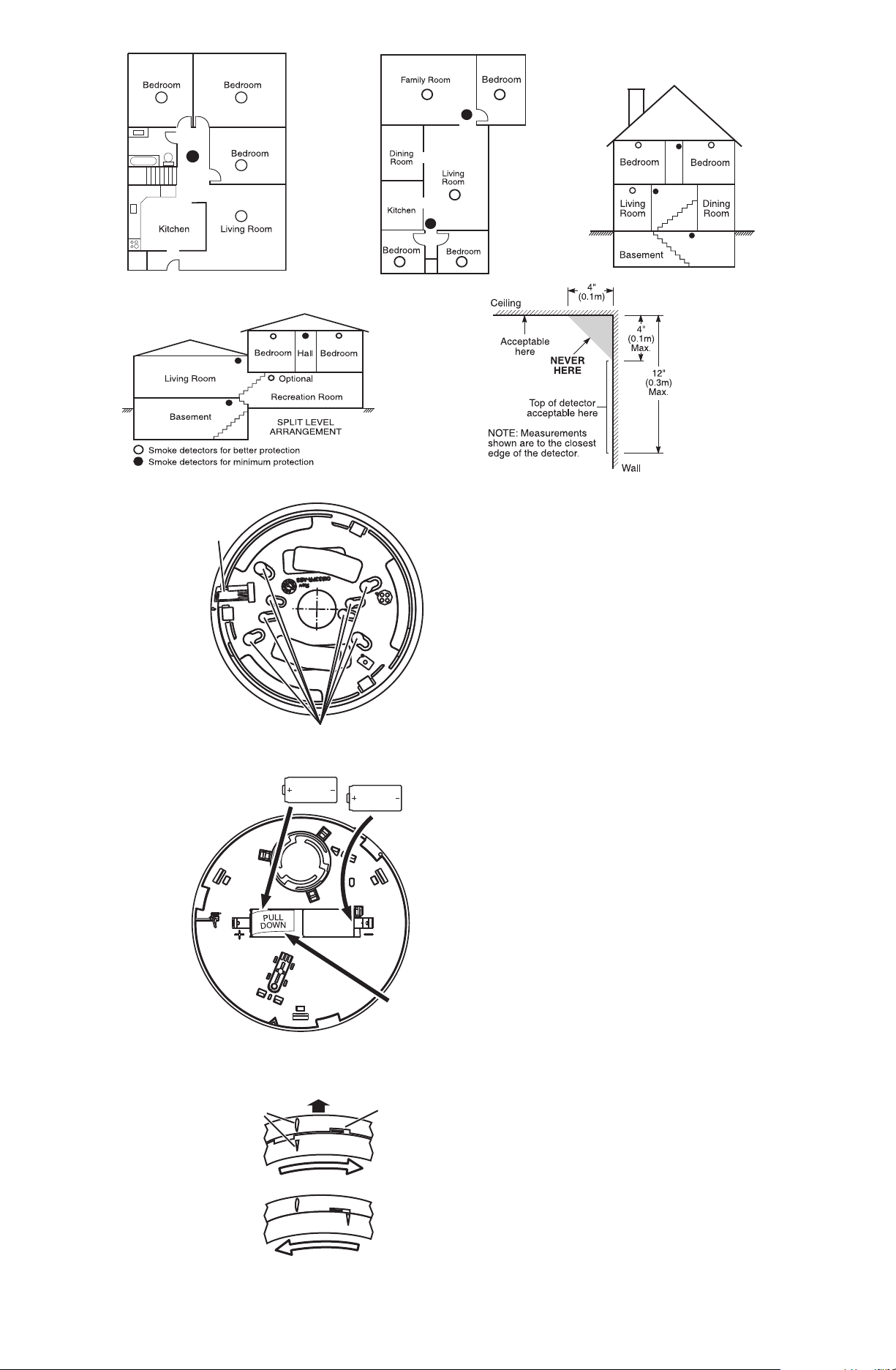
1. Smoke Detector Placement
On smooth ceilings, detectors may be spaced 9.1m (30 feet) apart
as a guide. Other spacing may be required depending on ceiling
height, air movement, the presence of joists, uninsulated ceilings,
etc. Consult National Fire Alarm Code NFPA 72 Chapter 11, CAN/
ULC-S553-02 or other appropriate national standards for installation recommendations.
•DoNOT locate smoke detectors at the top of peaked or gabled
ceilings; the dead air space in these locations may prevent the unit
from detecting smoke. Avoid areas with turbulent air flow, such
as near doors, fans or windows. Rapid air movement around the
detector may prevent smoke from entering the unit.
•DoNOT locate detectors in areas of high humidity.
•DoNOT locate detectors in areas where the temperature rises
above 38ºC (100ºF) or falls below 5ºC (41ºF).
Install Smoke detectors in accordance with NFPA 72, Chapter 11.
“Smoke detectors shall be installed outside of each sleeping area in
the immediate vicinity of the bedrooms and on each additional
story of the family living unit, including basements and excluding
crawl spaces and unfinished attics. In new construction, a smoke
detector also shall be installed in each sleeping room.”
2. Mount Smoke Detector Backplate
Secure backplate to
the mounting surface using the screws
Locking
Ta b
provided.
CAUTION: The dust
cover protects the
unit when not in
service. Remove the
dust cover before
use.
Mounting Holes
3. Install Batteries
If batteries are not
installed, install batteries in the
sequence indicated.
Use only approved
Panasonic CR123A,
Insert
Last
3V CR123A
3V CR123A
Insert
First
Sanyo CR123A or
Duracell DL123A
batteries. If batteries
are installed, remove
the “Pull” tab to
activate.
CAUTION: Without
batteries the unit
cannot be
mounted onto the
base plate properly! (WS4916 Australian version
only).
4. Mounting
• Detector Installation
Position the detector on
to the base plate using
the detector and base
plate alignment marks.
Mounting
Surface
Alignment
Marks
Detector
PULL
DOWN
Tab
Backplate
Tabs
Press the detector gently
in place while rotating the
CLOSE
detector clockwise until
the detector snaps into
place. Remove the side
tab from the locking tab
to lock in place (optional).
• Removal
OPEN
Depress tab with a small slotted screwdriver. Rotate detector
counter-clockwise until the alignment marks line up. Remove
detector.
Installer Compensation Reset
Cleaning or replacement of the smoke sensor chamber changes the
background signal/noise of the detector; this requires the drift compensation be reset. Compensation trouble is one of the faults indicated when the LED indicator is OFF while the sounder is chirping.
1. Remove batteries, then short the detector battery contacts for
5 seconds to power down unit.
2.Replace batteries to power up unit while pressing the test
button.
3.The tamper switch must not be pressed.
4.The LED will flash when 5 seconds has elapsed. Release the
test button within 2 seconds of the LED flash.
5.The LED will flash every 2 seconds for 1 minute. During this
period, the detector must be mounted.
Allow an additional 2 minutes for the detector to make background level checks.
6.Test the detector to verify normal operation.
5. Test Unit
NOTE: The central monitoring station (if used) should be notified
prior to the test being generated. This will prevent a false alarm
and an unnecessary response from the central monitoring station.
Initiate test by pressing the test button for 5 seconds minimum.
Alarm activation is indicated by the flashing LED, the sounder, and
transmission of the alarm signal to the control panel. The detector
restores to normal when the test button is released.
NOTE: Allow a minimum of 20 seconds after power up and ,
after test, alarm or tamper restore activations. Do not use test button when smoke is present.
NOTE: If the detector is in one of the following states when a test
is initiated; it will not enter an alarm state.
• Tamper, (detector not installed on mounting plate)
• Compensation Trouble
• Other internal faults that could prevent a smoke or heat alarm
NOTE: Smoke sensitivity of installed detectors can be measured
without removal or an alarm being generated using the FSD-100
Smoke Detector Test Meter.
To test the unit using the FSD-100, set the test meter up to read
devices as per the instructions supplied. Depress the test button on
the smoke detector for 1 second and release.
NOTE: If the test button is held for 5 seconds or longer, an alarm
will be generated.
Move the test meter over the center of the detector, wait until you
hear the test meter beep, remove the unit and the information can
be immediately reviewed. Please see the instructions supplied with
the FSD-100 Smoke Detector Test Meter for more information.
6. Device Enrollment
The 6-digit serial number located on the back of the smoke detector housing must be enrolled into the alarm control panel with
Installer programming. Refer to the receiver Installation Manual
for details. For placement tests remove detector from backplate for
one second (tamper) then reattach. Wait at least 30 seconds for test
result before activating again.

Owner’s Instructions
Fire Safety In The Home
Most fires occur in the home, and to minimize this danger, it is recommended that a household fire safety audit be conducted and a
family escape plan be developed.
Household Fire Safety Audit
1. Are all electrical appliances and outlets in safe condition?
Check for frayed cords, overloaded lighting circuits, etc. If you
are uncertain about the condition of your electrical appliances
or household service, have a professional evaluation.
2.Are all flammable liquids safely stored in closed containers,
and in a cool and well ventilated area? Cleaning the unit with
flammable liquids should be avoided.
3.Are hazardous materials (i.e., matches) out of the reach of
children?
4.Are furnaces and wood burning appliances properly installed,
clean, and in good working order? If in doubt, have a professional evaluation.
Family Escape Planning
There is often very little time between the detection of a fire and the
time it becomes deadly. Because of this, it is very important that a
family escape plan be developed and rehearsed.
• Every family member should participate in the escape plan.
• Study the possible escape routes from each location within the
house. Since many fires occur at night, special attention should be
given to the escape routes from sleeping quarters.
• It is essential that escape from a bedroom be possible without
opening the interior door. Consider the following when making
your escape plans:
• Ensure that doors and windows that open to the outside are eas-
ily opened. Ensure that they are not painted shut and that the
locking mechanisms operate smoothly.
• If opening or using the exit is too difficult for children, the elderly
or handicapped, plans for their rescue should be developed. This
plan includes making sure that those who are to perform the rescue can promptly hear the fire warning signal.
• If the exit is above the ground level, an approved fire ladder or
rope should be provided, as well as training in its use.
• Exits on the ground level should be kept clear. Be sure to remove
snow from exterior patio doors in the winter and that outdoor
furniture or equipment does not block exits.
• The family should have a predetermined assembly point where
everyone can be accounted for; for example, across the street or
at a neighbor’s house.
• Once everyone is out of the house, call the Fire Department.
• A good plan emphasizes a quick escape. Do not investigate first
or attempt to fight the fire, and do not attempt to rescue belongings or valuables as this takes up time. Once outside, do not reenter the house; wait for the Fire Department.
• Write the plan down and rehearse it frequently so that should
an emergency ever arise, everyone will know what to do.
Revise the plan as conditions change; for example, when
there are more or fewer family members in the home or if
there are changes to the house.
• Make sure your fire warning system is operational by conducting
weekly tests. If you are unsure about system operation, contact
your smoke detector installer or dealer.
• DSC recommends that you contact your local Fire Department
and request further information on home fire safety and escape
planning. If available, have your local fire prevention officer conduct an in-house fire safety inspection.
Testing Your Smoke Detector
Follow the test procedure described here or contact your smoke
detector dealer or installer for testing instructions. DSC
recommends that you test the entire alarm system at least once
a week to verify the operation of all system functions.
Smoke Detector Unit Test
Initiate test by pressing the test button for 5 seconds (min.), the
sounder makes clicking noises during this time. Press the button
until the unit alarm sounds, an alarm should be sent to the control
panel. When the button is released, the alarm should cease. If this
does not occur, ensure batteries are the correct type, in good condition and are installed correctly (see 3. Install Batteries in the
Installation Instructions section).
Upon completing the functional testing of the smoke detector,
check the unit’s sensing chamber to ensure proper operation. To
test the sensing chamber, wave a lit cotton wick or punk stick
around the outside of the unit until a generous amount of smoke
enters the sensing chamber or the unit alarms. If the smoke detector does not function properly, call your smoke detector installer or
dealer for service.
Owner’s Maintenance
The smoke detector is designed to require minimum maintenance.
If the case becomes dusty, vacuum with a small brush attachment.
If the case is greasy, wipe the case gently with a soft cloth slightly
dampened with soapy water.
Never disassemble the smoke detector; there are no user
serviceable parts inside the unit. You may only remove detector
from backplate to replace batteries if not serviced by installer.
When replacing the batteries, follow the instructions specified
within the Installation Instructions, Item 3 Install Batteries.
CAUTION: This product uses lithium batteries, improper
handling may result in a HEAT, EXPLOSION or FIRE causing
personal injury. DO NOT recharge batteries. Follow the battery
manufacturer’s safety instructions. Dispose of used batteries in
accordance with the regulations in your area.
Never paint the unit. Paint may prevent smoke from entering
the unit. If you are planning renovations or repainting, contact
your installer and ask that the unit be temporarily removed until
work is complete.
If the unit is located in an area where it is exposed to high levels of
dust or insects and causes false alarms, it may require service; contact your smoke detector installer or dealer.
Testing and maintenance procedures shall be in accordance with
CAN/ULC-S552-02.
Specifications
• Diameter (base): 5.8in (147mm)
• Height (including base): 2.077in (528mm)
• Alarm Sensitivity (threshold) UL: 3.0±0.8%/ft obscuration, ULC:
2.0±0.5 %/ft obscuration
• Alarm Sensitivity (threshold) EU: complies with EN54-7
• Warning threshold: 75% of alarm threshold for 120 seconds
• Heat Alarm: 135ºF (57ºC)
• Supervisory Transmission Frequency UL, ULC: 64 min. intervals
• Supervisory Transmission Frequency EU: 12 minute intervals
• Sounder Alarm Pattern UL, EU: evacuation temporal pattern
• Sounder Alarm Pattern ULC: continuous beeps
• Operating Temperature with Heat Detector:
32º-100ºF (0º-37.8ºC)
• Operating Temperature for Smoke Alarm (Australian version):
41º-113ºF (5º-45ºC)
• Humidity: 5%-95% RH, non-condensing
• Batteries (2) CR123A
• Low Battery Detection Low battery 14 days remaining
• Approved Batteries: Panasonic CR123A, Sanyo CR123A and
Duracell DL123A
Alarm Indications
Condition LED Sounder Transmission
Normal Flash 1/50s OFF Supervisory
Alarm Smoke Flash 1/1s
Alarm Heat Flash 1/1s
Early Warning
Smoke
Compensation
Trouble High
Compensation
Trouble Low
Sensor/
Internal Fault
Low Battery
0 - 7 days
Low Battery
0 - 7 days & Test or
Alarm
Low Battery After
7 days
Tamper Flash 1/50s OFF Tamper
Flash 1/50s CHIRP None
OFF CHIRP Trouble
OFF CHIRP Trouble
OFF CHIRP Trouble
Flash 1/50s
Flash 1/50s
Flash 1/50s
This product has been approved by the California State Fire
Marshal (CSFM) pursuant to section 13144.1 of the California
Health and Safety Code. See CSFM Listing No. 7272-1273:125
for allowable values and/or conditions for use concerning material presented in this document. The approval is subject to reexamination, revision and possible cancellation.
Temporal or
Steady
Temporal or
Steady
OFF Low Battery
CHIRP
CHIRP
Low Battery
Low Battery
Alarm
Alarm

The smoke alarm WS4916 has a recommended service life of 10
years under normal conditions of use. Please refer to the label
applied to the device indicating the recommended replacement
year.
For servicing the unit or replacement batteries please call your
installation company that provided you with the alarm system.
NOTE: In Australia the device shall not be installed in locations
where the normal ambient temperature is lower than 41°F (5°C)
or higher than 113°F (45°C).
This manual shall be used in conjunction with the Installation
Manual of the alarm control panel. All the instructions specified
within that manual must be observed.
Limited Warranty
Digital Security Controls warrants that for a period of twelve months from the date of purchase, the product shall be free of defects in materials and workmanship under normal use and that in fulfillment of any
breach of such warranty, Digital Security Controls shall, at its option, repair or replace the defective equipment upon return of the equipment to its repair depot. This warranty applies only to defects in parts and
workmanship and not to damage incurred in shipping or handling, or damage due to causes beyond the
control of Digital Security Controls such as lightning, excessive voltage, mechanical shock, water damage, or damage arising out of abuse, alteration or improper application of the equipment.
The foregoing warranty shall apply only to the original buyer, and is and shall be in lieu of any and all
other warranties, whether expressed or implied and of all other obligations or liabilities on the part of Digital Security Controls. Digital Security Controls neither assumes responsibility nor authorizes any other
person purporting to act on its behalf to modify or to change this warranty, nor to assume for it any other
warranty or liability concerning this product.
In no event shall Digital Security Controls be liable for any direct, indirect or consequential damages, loss
of anticipated profits, loss of time or any other losses incurred by the buyer in connection with the purchase, installation or operation or failure of this product.
Smoke Detectors: Smoke detectors that are a part of this system may not properly alert occupants of a
fire for a number of reasons, some of which follow. The smoke detectors may have been improperly
installed or positioned. Smoke may not be able to reach the smoke detectors, such as when the fire is in a
chimney, walls or roofs, or on the other side of closed doors. Smoke detectors may not detect smoke from
fires on another level of the residence or building.
Every fire is different in the amount of smoke produced and the rate of burning. Smoke detectors cannot
sense all types of fires equally well. Smoke detectors may not provide timely warning of fires caused by
carelessness or safety hazards such as smoking in bed, violent explosions, escaping gas, improper storage
of flammable materials, overloaded electrical circuits, children playing with matches or arson.
Even if the smoke detector operates as intended, there may be circumstances when there is insufficient
warning to allow all occupants to escape in time to avoid injury or death.
Warning: Digital Security Controls recommends that the entire system be completely tested on a regular
basis. However, despite frequent testing, and due to, but not limited to, criminal tampering or electrical
disruption, it is possible for this product to fail to perform as expected.
Important Information: Changes or modifications not expressly approved by Digital Security Controls
could void the user’s authority to operate this equipment.
FCC Compliance Statement
CAUTION: Changes or modifications not expressly approved by DSC could void your authority to use
this equipment.
This equipment generates and uses radio frequency energy and if not installed and used properly, in strict
accordance with the manufacturer’s instructions, may cause interference to radio and television reception.
It has been type tested and found to comply with the limits for Class B device in accordance with the specifications in Subpart “B” of Part 15 of FCC Rules, which are designed to provide reasonable protection
against such interference in any residential installation. However, there is no guarantee that interference
will not occur in a particular installation. If this equipment does cause interference to television or radio
reception, which can be determined by turning the equipment off and on, the user is encouraged to try to
correct the interference by one or more of the following measures:
• Re-orient the receiving antenna
• Relocate the alarm control with respect to the receiver
• Move the alarm control away from the receiver
• Connect the alarm control into a different outlet so that alarm control and receiver are on different circuits.
If necessary, the user should consult the dealer or an experienced radio/television technician for additional
suggestions. The user may find the following booklet prepared by the FCC helpful: “How to Identify and
Resolve Radio/Television Interference Problems”. This booklet is available from the U.S. Government
Printing Office, Washington, D.C. 20402, Stock # 004-000-00345-4.
Industry Canada Compliance Statement: This Class B digital apparatus meets all requirements of the
Canadian interference-causing equipment regulations.
Cet appareil numérique de la Classe B respecte toutes les exigences de règlement sur le matériel brouilleur
du Canada.
IC:160A - WLS916NB
The term "IC:" before the radio certification number only signifies that Industry Canada technical specifications were met.
+HUHE\ '6& GHFODUHV WKDW WKLV GHYLFH LV LQ FRPSOLDQFH ZLWK WKH HVVHQWLDO
UHTXLUHPHQWVDQGRWKHUUHOHYDQWSURYLVLRQVRI'LUHFWLYH(&
7KH FRPSOHWH 577( 'HFODUDWLRQ RI &RQIRUPLW\ FDQ EH IRXQG DW
KWWSZZZGVFFRPOLVWLQJVBLQGH[DVS[
&=( '6& MDNR Y¿UREFH SURKODģXMH ŀH WHQWR Y¿UREHN MH Y VRXODGX VH YģHPL
UHOHYDQWQ¯PLSRŀDGDYN\VPÝUQLFH(&
'$1'6&HUNO¨UHUKHUYHGDWGHQQHNRPSRQHQWHQRYHUKROGHUDOOHYLNWLJHNUDYVDPW
DQGUHEHVWHPPHOVHUJLWWLGLUHNWLY(&
'87 +LHUELM YHUNODDUW '6& GDW GLW WRHVWHO LQ RYHUHHQVWHPPLQJLV PHW GHHLVHQ HQ
EHSDOLQJHQYDQULFKWOLMQ(&
),1'6&YDNXXWWDDODLWWHHQW¦\WW¦Y¦QGLUHNWLLYLQ(&ROHQQDLVHWYDDWLPXNVHW
)5( 3DU OD SU«VHQWH '6&G«FODUH TXH FH GLVSRVLWLI HVW FRQIRUPH DX[ H[LJHQFHV
HVVHQWLHOOHVHWDXWUHVVWLSXODWLRQVSHUWLQHQWHVGHOD'LUHFWLYH(&
*(5+LHUGXUFKHUNO¦UW'6&GD¡GLHVHV *HU¦WGHQHUIRUGHUOLFKHQ%HGLQJXQJHQXQG
9RUUDXVHW]XQJHQGHU5LFKWOLQLH(&HQWVSULFKW
*5(˂˜˞ ˱ˬ˲ ˭˞ˮ˹˪˱ˬ˯ ˤ'6& ˡˤ˨˻˪ˢ˦ ˹˱˦ ˞˲˱˛ˤ˰˲˰˧ˢ˲˛ ˢ˜˪˞˦ ˰˺˩˳˶˪ˤ ˩ˢ˱˦˯
ˬ˲˰˦˻ˡˤ˯˞˭˞˦˱˛˰ˢ˦˯˧˞˦˩ˢ˹˨ˢ˯˱˦˯˙˨˨ˢ˯˰˴ˢ˱˦˧˚˯˞˪˞˳ˬˮ˚˯˱ˤ˯ˍˡˤˠ˜˞˯(&
,7$ &RQ OD SUHVHQWH OD 'LJLWDO 6HFXULW\ &RQWUROV GLFKLDUD FKH TXHVWR SURGRWWR ª
FRQIRUPH DL UHTXLVLWL HVVHQ]LDOL HG DOWUH GLVSRVL]LRQL ULOHYDQWL UHODWLYH DOOD 'LUHWWLYD
&(
125'6&HUNO¨UHU DWGHQQHHQKHWHQ HULVDPVYDUPHGGH JUXQQOHJJHQGHNUDYRJ
ºYULJHUHOHYDQWHNUDYLGLUHNWLY()
32/'6&RĝZLDGF]DľHXU]ÇG]HQLHMHVWZ]JRGQRĝFL]]DVDGQLF]\PLZ\PDJDQLDPL
RUD]SR]RVWDĄ\PLVWRVRZQ\PLSRVWDQRZLHQLDPL'\UHNW\Z\:(
3253RU HVWHPHLR D'6& GHFODUD TXHHVWH HTXLSDPHQWRHVW£ HP FRQIRUPLGDGH
FRP RV UHTXLVLWRV HVVHQFLDLV H RXWUDV GHWHUPLQD©·HV UHOHYDQWHV GD 'LUHFWLYD
(&
63$3RU OD SUHVHQWH '6& GHFODUD TXH HVWH HTXLSR HVW£ HQ FRQIRUPLGDG FRQ ORV
UHTXLVLWRVHVHQFLDOHV\RWURVUHTXLVLWRVUHOHYDQWHVGHOD'LUHFWLYD(&
6:('6& EHNU¦IWDU K¦UPHG DWW GHQQD DSSDUDWXSSI\OOHUGHY¦VHQWOLJD NUDYHQ RFK
DQGUDUHOHYDQWDEHVW¦PPHOVHUL'LUHNWLYHW(&
© 2011 Tyco International Ltd. and its Respective Companies. All Rights Reserved.
Tech Support: 1-800-387-3630 (Canada & U.S.) or 905-760-3000 • www.dsc.com
Printed in Czech 17
IMPORTANT - READ CAREFULLY: DSC Software purchased with or without Products and
Components is copyrighted and is purchased under the following license terms:
• This End-User License Agreement (“EULA”) is a legal agreement between You (the company, individual or entity who acquired the Software and any related Hardware) and Digital Security Controls, a division of Tyco Safety Products Canada Ltd. (“DSC”), the manufacturer of the integrated security systems
and the developer of the software and any related products or components (“HARDWARE”) which
You acquired.
• If the DSC software product (“SOFTWARE PRODUCT” or “SOFTWARE”) is intended to be accompanied by HARDWARE, and is NOT accompanied by new HARDWARE, You may not use, copy or
install the SOFTWARE PRODUCT. The SOFTWARE PRODUCT includes computer software, and
may include associated media, printed materials, and “online” or electronic documentation.
• Any software provided along with the SOFTWARE PRODUCT that is associated with a separate
end-user license agreement is licensed to You under the terms of that license agreement.
• By installing, copying, downloading, storing, accessing or otherwise using the SOFTWARE PRODUCT, You agree unconditionally to be bound by the terms of this EULA, even if this EULA is deemed
to be a modification of any previous arrangement or contract. If You do not agree to the terms of this
EULA, DSC is unwilling to license the SOFTWARE PRODUCT to You, and You have no right to use
it.
SOFTWARE PRODUCT LICENSE
The SOFTWARE PRODUCT is protected by copyright laws and international copyright treaties, as well
as other intellectual property laws and treaties. The SOFTWARE PRODUCT is licensed, not sold.
1. GRANT OF LICENSE This EULA grants You the following rights:
(a)Software Installation and Use - For each license You acquire, You may have only one copy of the
SOFTWARE PRODUCT installed.
(b)Storage/Network Use - The SOFTWARE PRODUCT may not be installed, accessed, displayed, run,
shared or used concurrently on or from different computers, including a workstation, terminal or other
digital electronic device (“Device”). In other words, if You have several workstations, You will have to
acquire a license for each workstation where the SOFTWARE will be used.
(c)Backup Copy - You may make back-up copies of the SOFTWARE PRODUCT, but You may only
have one copy per license installed at any given time. You may use the back-up copy solely for archival
purposes. Except as expressly provided in this EULA, You may not otherwise make copies of the SOFTWARE PRODUCT, including the printed materials accompanying the SOFTWARE.
2. DESCRIPTION OF OTHER RIGHTS AND LIMITATIONS
(a)Limitations on Reverse Engineering, Decompilation and Disassembly - You may not reverse engineer,
decompile, or disassemble the SOFTWARE PRODUCT, except and only to the extent that such activity
is expressly permitted by applicable law notwithstanding this limitation. You may not make any changes
or modifications to the Software, without the written permission of an officer of DSC. You may not
remove any proprietary notices, marks or labels from the Software Product. You shall institute reasonable
measures to ensure compliance with the terms and conditions of this EULA.
(b)Separation of Components - The SOFTWARE PRODUCT is licensed as a single product. Its component parts may not be separated for use on more than one HARDWARE unit.
(c)Single INTEGRATED PRODUCT - If You acquired this SOFTWARE with HARDWARE, then the
SOFTWARE PRODUCT is licensed with the HARDWARE as a single integrated product. In this case,
the SOFTWARE PRODUCT may only be used with the HARDWARE as set forth in this EULA..
(d)Rental - You may not rent, lease or lend the SOFTWARE PRODUCT. You may not make it available
to others or post it on a server or web site.
(e)Software Product Transfer - You may transfer all of Your rights under this EULA only as part of a permanent sale or transfer of the HARDWARE, provided You retain no copies, You transfer all of the
SOFTWARE PRODUCT (including all component parts, the media and printed materials, any upgrades
and this EULA), and provided the recipient agrees to the terms of this EULA. If the SOFTWARE PRODUCT is an upgrade, any transfer must also include all prior versions of the SOFTWARE PRODUCT.
(f) Termination - Without prejudice to any other rights, DSC may terminate this EULA if You fail to comply with the terms and conditions of this EULA. In such event, You must destroy all copies of the SOFTWARE PRODUCT and all of its component parts.
(g)Trademarks - This EULA does not grant You any rights in connection with any trademarks or service
marks of DSC or its suppliers.
3. COPYRIGHT - All title and intellectual property rights in and to the SOFTWARE PRODUCT
(including but not limited to any images, photographs, and text incorporated into the SOFTWARE
PRODUCT), the accompanying printed materials, and any copies of the SOFTWARE PRODUCT, are
owned by DSC or its suppliers. You may not copy the printed materials accompanying the SOFTWARE
PRODUCT. All title and intellectual property rights in and to the content which may be accessed through
use of the SOFTWARE PRODUCT are the property of the respective content owner and may be protected by applicable copyright or other intellectual property laws and treaties. This EULA grants You no
rights to use such content. All rights not expressly granted under this EULA are reserved by DSC and its
suppliers.
4. EXPORT RESTRICTIONS - You agree that You will not export or re-export the SOFTWARE
PRODUCT to any country, person, or entity subject to Canadian export restrictions.
5. CHOICE OF LAW - This Software License Agreement is governed by the laws of the Province of
Ontario, Canada.
6. ARBITRATION - All disputes arising in connection with this Agreement shall be determined by final
and binding arbitration in accordance with the Arbitration Act, and the parties agree to be bound by the
arbitrator’s decision. The place of arbitration shall be Toronto, Canada, and the language of the arbitration shall be English.
7. LIMITED WARRANTY
(a) NO WARRANTY - DSC PROVIDES THE SOFTWARE “AS IS” WITHOUT WARRANTY. DSC
DOES NOT WARRANT THAT THE SOFTWARE WILL MEET YOUR REQUIREMENTS OR
THAT OPERATION OF THE SOFTWARE WILL BE UNINTERRUPTED OR ERROR-FREE.
(b) CHANGES IN OPERATING ENVIRONMENT - DSC shall not be responsible for problems caused
by changes in the operating characteristics of the HARDWARE, or for problems in the interaction of the
SOFTWARE PRODUCT with non-DSC-SOFTWARE or HARDWARE PRODUCTS.
(c) LIMITATION OF LIABILITY; WARRANTY REFLECTS ALLOCATION OF RISK - IN ANY
EVENT, IF ANY STATUTE IMPLIES WARRANTIES OR CONDITIONS NOT STATED IN THIS
LICENSE AGREEMENT, DSC’S ENTIRE LIABILITY UNDER ANY PROVISION OF THIS
LICENSE AGREEMENT SHALL BE LIMITED TO THE GREATER OF THE AMOUNT ACTUALLY PAID BY YOU TO LICENSE THE SOFTWARE PRODUCT AND FIVE CANADIAN DOLLARS (CAD$5.00). BECAUSE SOME JURISDICTIONS DO NOT ALLOW THE EXCLUSION OR
LIMITATION OF LIABILITY FOR CONSEQUENTIAL OR INCIDENTAL DAMAGES, THE
ABOVE LIMITATION MAY NOT APPLY TO YOU.
(d) DISCLAIMER OF WARRANTIES - THIS WARRANTY CONTAINS THE ENTIRE WARRANTY AND SHALL BE IN LIEU OF ANY AND ALL OTHER WARRANTIES, WHETHER
EXPRESSED OR IMPLIED (INCLUDING ALL IMPLIED WARRANTIES OF MERCHANTABILITY OR FITNESS FOR A PARTICULAR PURPOSE) AND OF ALL OTHER OBLIGATIONS OR
LIABILITIES ON THE PART OF DSC. DSC MAKES NO OTHER WARRANTIES. DSC NEITHER
ASSUMES NOR AUTHORIZES ANY OTHER PERSON PURPORTING TO ACT ON ITS BEHALF
TO MODIFY OR TO CHANGE THIS WARRANTY, NOR TO ASSUME FOR IT ANY OTHER
WARRANTY OR LIABILITY CONCERNING THIS SOFTWARE PRODUCT.
(e) EXCLUSIVE REMEDY AND LIMITATION OF WARRANTY - UNDER NO CIRCUMSTANCES SHALL DSC BE LIABLE FOR ANY SPECIAL, INCIDENTAL, CONSEQUENTIAL OR
INDIRECT DAMAGES BASED UPON BREACH OF WARRANTY, BREACH OF CONTRACT,
NEGLIGENCE, STRICT LIABILITY, OR ANY OTHER LEGAL THEORY. SUCH DAMAGES
INCLUDE, BUT ARE NOT LIMITED TO, LOSS OF PROFITS, LOSS OF THE SOFTWARE PRODUCT OR ANY ASSOCIATED EQUIPMENT, COST OF CAPITAL, COST OF SUBSTITUTE OR
REPLACEMENT EQUIPMENT, FACILITIES OR SERVICES, DOWN TIME, PURCHASERS
TIME, THE CLAIMS OF THIRD PARTIES, INCLUDING CUSTOMERS, AND INJURY TO PROPERTY. WARNING:
DSC recommends that the entire system be completely tested on a regular basis. However, despite frequent testing, and due to, but not limited to, criminal tampering or electrical disruption, it is possible for
this SOFTWARE PRODUCT to fail to perform as expected.
1134
DSC, Toronto, Canada
2010
EN54-5/A1 (2002)
EN54-7/A2 (2006)
Point type smoke and heat detector
1134-CPD-001

WS4916 Serie Funk-Rauchmelder
Installations- und Bedienungsanleitung
Lesen Sie diese Anleitungen aufmerksam durch, bevor Sie den WS4916 Funk-Rauchmelder installieren und in Betrieb nehmen
Einleitung
Der WS4916 ist ein kombinierter Funk-Rauch-, und Wärmemelder mit
optischer Detektion, Temperaturgrenzwert- sowie Thermodifferenzial
Auswertung und internem piezoelektrischem Alarm. Es sind vier Versionen
lieferbar: US-Version (UL), kanadische Version (ULC), internationale Version
(EU) und australische Version (AUS).
HINWEIS: Die Wärmeerkennung basiert auf der Temperaturanstiegsrate
und wurde von UL/ULC nicht untersucht.
HINWEIS: Die australische Version umfasst nicht den Wärmemelder.
LED/Testknopf
Piezo-Sirene
Einstellmarkierungen
Bedienungshinweise
Das Gerät testet alle 7 bis 8 Sekunden auf Rauch- oder
Wärmealarmzustand. Hierbei führt das Gerät ebenfalls eine Selbstdiagnose
durch und überprüft auf Sabotage und Fehlfunktionen. Während des
Normalbetriebs blinkt die LED alle 50 Sekunden und die Sirene ertönt nicht.
Rauchalarm
Der Rauchmelder löst einen Alarm aus, wenn der Signalpegel den „Alarm“
Grenzwert übersteigt und stellt sich automatsich zurück, wenn der
Signalpegel unter den Alarm „Rückstell“ Grenzwert fällt. Während eines
Alarms blinkt die LED 1/Sekunde und die Sirene ertönt mit dem
unterbrochenen Evakuierungssignal (UL, EU) oder kontinuierlichen
Signaltönen (ULC).
Der Rauchmelder hat einen voreingestellten Warngrenzwert bei 75 % des
Alarmgrenzwerts. Bleibt der Signalpegel länger als 120 Sekunden oberhalb
dieses Grenzwerts, jedoch unterhalb des Alarmgrenzwerts, so begibt sich
der Melder in den „Warnstatus“. Fällt der Signalpegel unter den frühen
„Rückstell“ Warngrenzwert, so stellt sich der Melder automatisch in den
Normalstatus zurück. Steigt der Signalpegel über den Alarmgrenzwert, so
gibt der Melder Alarm. Die LED blinkt im Warnstatus und die Sirene gibt alle
50 Sekunden einen Signalton ab.
HINWEIS: Diese Funktion dient als Warnung, sofern die Umgebung
fortgesetzt nahe am Alarmgrenzwert ist und um ausreichend Zeit für
Ermittlungen und entweder Flucht oder Korrektur der Situation zu
lassen.
Rauch - Driftkorrektur
Der Melder kompensiert automatisch für langfristige umweltbedingte
Veränderungen, um eine kontinuierliche Rauchempfindlichkeit zu halten.
Erreicht die Driftkorrektur ihren hohen oder niedrigen Grenzwert der
Einstellung, dann begibt sich der Melder in Störstatus.
Wärmealarm
Der Wärmemelder löst einen Alarm aus, wenn die Temperatur den
Grenzwert übersteigt (135 ºF/57 ºC) und stellt sich automatisch zurück,
wenn die Temperatur unter den Grenzwert abfällt (Rückstellung). Der
Melder löst ebenfalls einen Wärmealarm aus, wenn es einen steilen Anstieg
der Temperatur über einen kurzen Zeitraum gibt. Während eines Alarms
blinkt die LED 1/Sekunde und die Sirene ertönt mit dem unterbrochenen
Evakuierungssignal (UL, EU) oder kontinuierlichen Signaltönen (ULC).
Sabotage
Das Abnehmen des Melders von der Montageplatte löst einen
„Sabotagealarm“ aus. Der Sabotagezustand wird zurückgestellt, nachdem
der Melder wieder auf der Montageplatte befestigt ist.
Funk-Übertragungen
Eine Überwachungsmeldung wird in Abständen von 64 Minuten
(12 Minuten bei EU-Modell) an die Alarmzentrale übertragen. Wird das
Signal nicht empfangen, so geht die Alarmzentrale davon aus, dass der
Melder fehlt.
Der Melder überträgt:
• Alarm / Alarm-Rückstellung - (Wärme- oder Rauchalarm). Übertragung
zum Zeitpunkt des Auftretens.
• Sabotage / Sabotage-Rückstellung - (Sabotagekontakt aktiviert)
10 Sekunden maximale Verzögerung zur Rückstellung vor Übertragung.
• Batterien erschöpft - (Batterienspannung fällt unter den Grenzwert). Der
Batteriezustand wird zum Zeitpunkt der Überwachungsmeldung oder
sonstiger Übertragungen getestet und übertragen.
• Störung - (Melder Fehlfunktion oder Sensorkorrektur-Grenzwert
erreicht). Störungen werden zum Zeitpunkt des Auftretens übertragen
(eine Störung je Überwachungsintervall).
Batterien
Der WS4916 wird von zwei 3 VDC Lithiumbatterien versorgt.
Benutzen Sie NUR die aufgeführten Batterien.
Der Grenzwert für erschöpfte Batterien ist so eingestellt, dass die Batterien
wenigstens weitere 14 Tage in Betrieb sind, zu diesem Zeitpunkt überträgt
der Melder das Signal „Batterien erschöpft“. Sind die Batterien auch nach
weiteren 7 Tagen erschöpft, nachdem sie unter den Grenzwert abgefallen
sind, ertönt bis zur Totalausfall der Batterien alle 48 Sekunden ein Signalton.
Während der ersten 7 Tage nach Batterieerkennung (kein Signalton) gibt
die Sirene beim Testen des Melders oder bei Alarm einen Signalton ab und
signalisiert weiterhin, bis die Batterien vollständig erschöpft sind.
Austauschbatterien erhalten Sie vom Vertrieb, Ihrem Installateur, im
Baumarkt oder Supermarkt.
Installation
Der WS4916 Serie Funk-Rauchmelder muss in einer Umgebung installiert
und benutzt werden, die einen Verschmutzungsgrad von max. 2 und
Überspannung Kategorie II an NICHT GEFÄHRDETEN STANDORTEN
aufweist sowie nur in geschlossenen Räumen.
Das Gerät darf nur von KUNDENDIENSTMITARBEITERN installiert werden
(KUNDENDIENSTMITARBEITER sind als Personen definiert, die eine
entsprechende technische Ausbildung und notwendige Erfahrung haben,
um sich der Gefahren bei der Durchführung der Arbeiten bewusst zu sein
und die Maßnahmen zur Verringerung der Risiken für sich und andere
ergreifen können).
1. Montageort für Rauchmelder
Auf glatten Zimmerdecken können Melder als Faustregel im Abstand von
9,1 m installiert werden. Andere Abstände richten sich nach Deckenhöhe,
Luftbewegung, Balken, nicht isolierten Decken usw. Ziehen Sie die
entsprechenden nationalen Bestimmungen zu Rate.
• Installieren Sie Rauchmelder NICHT oben in spitzen oder gegiebelten
Decken; der Totraum an diesen Standorten kann das Gerät an der
Raucherkennung hindern. Vermeiden Sie Bereiche mit Lufturbulenzen,
wie beispielsweise dicht an Türen, Ventilatoren oder Fenstern. Starke
Luftbewegungen in unmittelbarer Umgebung des Melders können den
Rauch daran hindern, in den Melder einzutreten.
• Montieren Sie Melder NICHT in Bereichen mit hoher Luftfeuchtigkeit.
• Montieren Sie Melder NICHT in Bereichen, in denen die Temperatur über
38 ºC (100 ºF) steigt oder unter 5 ºC (41 ºF) fällt.
Installieren Sie Rauchmelder entsprechend NFPA 72, Kapitel 11.
„Rauchmelder müssen außerhalb jedes Schlafbereichs in unmittelbarer
Nähe der Schlafzimmer sowie auf jeder weiteren Ebene des Hauses,
einschließlich Keller, jedoch nicht Kriechkeller und nicht ausgebaute
Dachgeschosse, installiert werden. Bei Neubauten muss ein Rauchmelder
ebenfalls in jedem Schlafzimmer installiert werden.“

Schlafzimmer Schlafzimmer
Wohnzimmer 2
Schlafzimmer
Schlafzimmer
WohnzimmerKüche
Schlafzimmer Schlafzimmer
Wohnzimmer
Keller
Rauchmelder für zusätzlichen Schutz
Rauchmelder für Mindestschutz
Optional
Gemeinschaftsraum
SPLIT-LEVEL-HAUS
Esszimmer
Küche
Schlafzimmer Schlafzimmer
Eingangs-
bereich
2. Rückplatte des Rauchmelders montieren
Schrauben Sie die Rückplatte
mit den mitgelieferten
Schrauben am Montageort an.
VORSICHT:
Der Staubschutz schützt
das Geräts, wenn es nicht
in Betrieb ist. Nehmen Sie
den Staubschutz vor der
Inbetriebnahme ab.
Verschluss
Montagebohrung
3. Batterien einsetzen
Sind keine Batterien
eingesetzt, so setzen Sie sie
bitte wie folgt ein. Benutzen
Zuletzt
einsetzen
Sie nur zugelassene
Panasonic CR123A, Sanyo
CR123A oder Duracell
DL123A Batterien. Waren
bereits Batterien eingesetzt,
so ziehen Sie den
Schutzstreifen zur
Aktivierung heraus.
VORSICHT:
Ohne Batterien kann das
Gerät nicht korrekt auf der
Montageplatte montiert
werden! (nur WS4916
australische Version).
Nase
HERUNTERDRÜCKEN
4. Montage
• Melder installieren
Setzen Sie den Melder auf
der Montageplatte auf und
benutzen Sie die
Markierungen auf Melder
und Montageplatte zum
Ausrichten. Drücken Sie den
Melder leicht an und drehen
Sie ihn nach rechts, bis er
einrastet. Entfernen Sie die
seitliche Nase, um den
Melder zu arretieren
(optional).
• Abnehmen
Drücken Sie die Nase mit einem kleinen Schraubendreher ein. Drehen
Sie den Melder nach links, bis die Markierungen ausgerichtet sind.
Nehmen Sie den Melder ab.
Einstell-
markierungen
3V CR123A
Montagefläche
Melder
SCHLIEßEN
ÖFFNEN
3V CR123A
Zuerst
einsetzen
Nasen
Rückplatte
Wohnzimmer
Zimmerdecke
Hier akzeptabel
NIEMALS
HIER
Oberkante Melder,
hier akzeptabel
HINWEIS: Maße an
nächster Kante
des Melders.
Max.
10 cm
Schlafzimmer
Wohnzimmer
Keller
Max.
10 cm
Wand
Max.
30 cm
Schlafzim-
Esszimmer
Korrektur-Rückstellung durch Installateur
Reinigung oder Austausch der Rauchsensorkammer ändern das
Hintergrundsignal des Melders und die Driftkorrektur muss zurückgestellt
werden. Korrekturstörung ist einer der angezeigten Defekte mit
ausgeschalteter LED und ertönender Sirene.
1. Entfernen Sie die Batterien, dann schließen Sie die Melder-
Batteriekontakte für 5 Sekunden kurz, um das Gerät zu deaktivieren.
2. Setzen Sie die Batterien ein und halten Sie den Testknopf gedrückt.
3. Der Sabotagekontakt darf nicht gedrückt werden.
4. Die LED blinkt nach Ablauf von 5 Sekunden. Lassen Sie den Testknopf
innerhalb von 2 Sekunden los, wenn die LED blinkt.
5. Die LED blinkt für 1 Minute alle 2 Sekunden. Während dieses Zeitraums
muss der Melder montiert werden.
Gewähren Sie dem Melder weitere 2 Minuten für den Hintergrundtest.
6. Testen Sie den Melder zur Bestätigung des Normalbetriebs.
5. Gerät testen
HINWEIS: Die Notrufzentrale (sofern angeschlossen) muss vor dem
Test informiert werden. Hierdurch vermeiden Sie Fehlalarm und eine
unnötige Anfahrt der Notrufzentrale.
Halten Sie den Testknopf für wenigstens 5 Sekunden gedrückt. Die
Alarmauslösung wird durch die blinkende LED, Sirene und Übertragung des
Alarmsignals an die Alarmzentrale angezeigt. Der Melder stellt sich zurück,
wenn Sie den Testknopf loslassen.
HINWEIS: Gewähren Sie dem Melder wenigstens 20 Sekunden, um
wieder zu aktivieren und sich zurückzustellen. Benutzen Sie den
Testknopf nicht, wenn Sie Rauch wahrnehmen.
HINWEIS: Befindet sich der Melder während des Tests in einem der
folgenden Zustände, so löst er keinen Alarm aus.
• Sabotage, (Melder nicht auf Montageplatte installiert)
• Korrekturstörung
• Andere interne Fehlfunktionen, die einen Rauch- oder Wärmealarm
verhindern
HINWEIS: Die Rauchempfindlichkeit des installierten Melders kann
mit dem FSD-100 Rauchmelder-Tester gemessen werden, ohne ihn
abzunehmen oder einen Alarm auszulösen.
Zum Testen des Geräts mit dem FSD-100, stellen Sie den Tester
entsprechend der mitgelieferten Anleitung zum Auslesen von Geräten ein.
Drücken Sie den Testknopf auf dem Rauchmelder für 1 Sekunde, dann
lassen Sie ihn wieder los.
HINWEIS: Wird der Testknopf für 5 Sekunden oder länger gedrückt,
wird ein Alarm ausgelöst.
Halten Sie den Tester über die Mitte des Melders, warten Sie ab, bis Sie vom
Tester den Signalton hören, dann nehmen Sie ihn ab und die Informationen
können direkt abgelesen werden. Einzelheiten finden Sie in der mit dem
FSD-100 Rauchmelder-Tester mitgelieferten Anleitung.
6. Gerät registrieren
Die 6-stellige Seriennummer befindet sich auf der Rückseite des Gehäuses
des Rauchmelders und muss auf der Alarmzentrale mit der InstallateurProgrammierung registriert werden. Siehe Bedienungsanleitung für den
Empfänger für Einzelheiten. Für Standorttests nehmen Sie den Melder von
der Rückplatte für eine Sekunde ab (Sabotage), dann montieren Sie ihn
wieder. Warten Sie wenigstens 30 Sekunden auf das Testergebnis, bevor Sie
den Melder erneut aktivieren.

Bedienungsanleitung
Branschutz im Haus
Die meisten Brände brechen in Häusern/Wohnungen aus. Zur Verringerung
dieser Gefahr empfehlen wir, dass Sie eine Brandschutzprüfung Ihres
Haushalts durchführen und einen Fluchtplan entwickeln.
Brandschutzprüfung Haushalt
1. Befinden sich Elektrogeräte und Steckdosen in einem sicheren Zustand?
Überprüfen Sie auf beschädigte Kabel, überlastete Stromkreise usw. Sind
Sie sich beim Zustand Ihrer Elektrogeräte nicht sicher, so nehmen Sie bitte
professionelle Hilfe in Anspruch.
2. Werden alle leicht entzündlichen Flüssigkeiten sicher in geschlossenen
Behältern in einem gut belüfteten kühlen Bereich gelagert? Vermeiden
Sie das Reinigen mit brennbaren Flüssigkeiten.
3. Befinden sich feuergefährliche Materialien (z.B. Streichhölzer) außerhalb
des Zugriffs von Kindern?
4. Sind Heizungs- und holzverbrennende Geräte ordnungsgemäß installiert,
sauber und in gutem Betriebszustand? Nehmen Sie zur Bewertung
professionelle Hilfe in Anspruch.
Fluchtwegplanung
Es bleibt häufig nur wenig Zeit zwischen dem Erkennen eines Feuers und dem
Zeitpunkt, an dem es zu einer tödlichen Gefahr wird. Daher ist es wichtig,
dass ein Fluchtplan für die Familie entwickelt und durchgespielt wird.
• Jedes Familienmitglied sollte an der Entwicklung des Fluchtplans
teilhaben.
• Studieren Sie mögliche Fluchtwege von jeder Position im Haus. Da viele
Feuer nachts ausbrechen, richten Sie ein besonderes Augenmerk auf die
Fluchtwege aus den Schlafzimmern.
• Die Flucht aus einem Schlafzimmer sollte ohne ein Öffnen der Zimmertür
möglich sein. Beachten Sie bitte bei der Aufstellung Ihres Fluchplans:
• Achten Sie darauf, dass sich alle Außenfenster und Türen einfach öffnen
lassen. Achten Sie darauf, dass sie nicht übergemalt sind und dass der
Schließmechanismus einwandfrei arbeitet.
• Ist das Öffnen des Ausgangs zu schwierig für Kinder, ältere oder
behinderte Personen, dann sollten Rettungspäne ausgearbeitet werden.
Das schließt ein, dass die Retter das Feuersignal rechtzeitig hören.
• Befindet sich der Ausgang über dem Erdgeschoss, so muss eine
zugelassene Feuerleiter oder ein Seil zur Verfügung stehen und der
Umgang damit geübt werden.
• Ebenerdige Ausgänge müssen freigehalten werden. Kehren Sie den
Schnee im Winter außerhalb von Terrassentüren; Gartenmöbel oder
Geräte dürfen die Ausgänge nicht blockieren.
• Jede Person muss den Sammelpunkt kennen (z.B. auf der anderen
Straßenseite oder im Haus eines Nachbarn).
• Rufen Sie die Feuerwehr, sobald alle Personen in Sicherheit sind.
• Ein guter Plan legt Wert auf eine schnelle Flucht. Versuchen Sie selbst
keine Brandermittlung oder Brandbekämpfung und sammeln Sie auch
keine Habseligkeiten ein, damit verlieren Sie nur wertvolle Zeit. Einmal im
Freien, gehen Sie nicht in das Haus zurück. Warten Sie auf die Feuerwehr.
• Schreiben Sie den Brand-Fluchtplan nieder und üben Sie ihn regelmäßig,
damit in einem Notfall jeder weiß, was er/sie zu tun hat. Überarbeiten Sie
den Plan, wenn es Veränderungen gibt, wie beispielsweise die Anzahl der
Personen im Haus oder bei baulichen Veränderungen.
• Achten Sie darauf, dass Ihr Brandmeldesystem in Betrieb ist und führen
Sie wöchentliche Tests durch. Sind Sie sich nicht ganz sicher, so wenden
Sie sich bitte an Ihren Installateur.
• Wir empfehlen, dass Sie sich an Ihre örtliche Feuerwehr wenden und
weitere Informationen zum Brandschutz und zur Fluchtwegplanung
erfragen. Falls möglich, bitten Sie Ihre örtliche Feuerwehr um eine
Brandinspektion vor Ort.
Rauchmelder testen
Folgen Sie dem hier beschriebenen Testablauf oder wenden Sie
sich an Ihren Fachhändler oder Installateur, um die
Testanleitungen zu erhalten. Wir empfehlen den Test des
gesamten Alarmsystems wenigstens einmal wöchentlich.
Rauchmelder Gerätetest
Starten Sie den Test, indem Sie den Testknopf für (mindestens) 5 Sekunden
gedrückt halten, die Sirene gibt ein Klickgeräusch ab. Halten Sie die Taste
gedrückt, bis das Gerät den Signalton ertönen lässt, ein Alarm wird an die
Alarmzentrale übertragen. Beim Loslassen der Taste verklingt der Alarm. Ist
das nicht der Fall, dann vergewisern Sie sich, dass die Batterien der korrekte
Typ, in gutem Zustand und korrekt installiert sind (siehe 3. Batterien
einsetzen im Abschnitt Installationsanleitung).
Nach dem Funktionstest des Rauchmelders überprüfen Sie die Messkammer
des Geräts auf korrekten Betrieb. Zum Testen der Messkammer schwenken
Sie einen brennenden Baumwolldocht oder ein Räucherstäbchen außen am
Gerät, bis eine gewissen Menge Rauch in die Messkammer eintritt oder
Alarm ausgelöst wird. Funktioniert der Rauchmelder nicht korrekt, so
wenden Sie sich bitte an Ihren Fachhändler oder Installateur.
Wartung
Der Rauchmelder benötigt nur ein Minimum an Wartung. Verstaubt das
Gehäuse, so saugen Sie es mit einer kleinen Bürste ab. Verölt das Gehäuse,
so wischen Sie es vorsichtig mit einem feuchten weichen Tuch und etwas
Neutralreiniger ab.
Zerlegen Sie den Rauchmelder nicht, es befinden sich keine wartbaren Teile
im Gerät. Nehmen Sie den Melder lediglich von der Rückplatte ab, um die
Batterien auszutauschen, sofern dies nicht vom Installateur durchgeführt
wird. Beim Austausch der Batterien folgen Sie den Anleitungen in Kapitel 3
der Installationsanleitung „Batterien einsetzen“.
VORSICHT: Dieses Gerät benutzt Lithiumbatterien,
unsachgemäße Handhabung kann zu ERHITZUNG, EXPLOSION
oder FEUER und Verletzungen führen. Batterien NICHT
aufladen. Befolgen Sie die Sicherheitshinweise des
Batterieherstellers. Entsorgen Sie erschöpfte Batterien
umweltgerecht.
Streichen Sie das Gerät nicht über. Die Farbe kann den Rauch am
Eindringen in das Gerät hindern. Wenden Sie sich bei Renovierungsarbeiten
an Ihren Installateur und lassen Sie ihn die Geräte vorübergehend abbauen.
Befindet sich das Gerät in einem Bereich mit hoher Staubentwicklung oder
Insekten und es löst Fehlalarme aus, dann ist eine Wartung durch Ihren
Installateur oder Fachhändler nötig.
Test und Wartung müssen entsprechend CAN/ULC-S552-02 durchgeführt
werden.
Spezifikationen
• Durchmesser (Grundplatte): 147 mm (5,8 Zoll)
• Höhe (einschließlich Grundplatte): 52,8 mm (2,077 Zoll)
• Alarmempfindlichkeit (Grenzwert) UL: 3,0±0,8 %/ft Verdunkelung durch
Rauch, ULC: 2,0±0,5 %/ft Verdunkelung durch Rauch
• Alarmempfindlichkeit (Grenzwert) EU: entsprechend EN54-7
• Warngrenzwert: 75 % des Alarm-Grenzwerts für 120 Sekunden
• Wärmealarm: 57 ºC (135 ºF)
• Überwachungsübertragungshäufigkeit UL, ULC: 64-Minuten-Intervalle
• Überwachungsübertragungshäufigkeit EU: 12-Minuten-Intervalle
• Sirenenalarm UL, EU: Evakuierung unterbrochenes Signal
• Sirenenalarm ULC: kontinuierliche Signaltöne
• Betriebstemperatur mit Wärmemelder:
0 ºC-37,8 ºC (32 ºF-100 ºF)
• Betriebstemperatur für Rauchalarm (australische Version):
5 ºC-45 ºC (41 ºF-113 ºF)
• Luftfeuchtigkeit: 5 %-95 % relative Luftfeuchtigkeit, nicht kondensierend
• Batterien (2) CR123A
• Erkennung Batterien erschöpft Erschöpfte Batterien noch 14 Tage
funktionsfähig
• Zugelassene Batterien: Panasonic CR123A, Sanyo CR123A und Duracell
DL123A
Alarmanzeigen
Zustand LED Sirene Übertragung
Normal Blinkt 1/50s AUS Überwachung
Alarm Rauch Blinkt 1/1s
Alarm Wärme Blinkt 1/1s
Frühwarnung
Rauch
Korrektur
Störung hoch
Korrektur
Störung niedrig
Sensor/
Interner Fehler
Batterien erschöpft
0-7Tage
Batterien erschöpft
0-7TageundTest
oder Alarm
Batterien erschöpft
nach 7 Tagen
Sabotage Blinkt 1/50s AUS Sabotage
Dieses Gerät ist durch den California State Fire Marshal (CSFM) gemäß
Abschnitt 13144.1 des California Health and Safety Code zugelassen. Siehe
CSFM-Listung Nr. 7272-1273:125 für zulässige Werte bzw. Umstände zur
Benutzung von in dieser Anleitung bezeichneten Materialien. Die Zulassung
unterliegt erneuter Überprüfung, Revision und möglicher Aufhebung.
Die optische Raucherkennung im WS4916 hat eine empfohlene
Lebensdauer von 10 Jahren unter normalen Nutzungsbedingungen. Siehe
Typenschild mit aufgedrucktem Jahr des Austauschs.
Zur Wartung des Geräts und zum Austausch der Batterien wenden Sie sich
bitten an den Installateur Ihres Alarmsystems.
Blinkt 1/50s SIGNALTON Keine
AUS SIGNALTON Störung
AUS SIGNALTON Störung
AUS SIGNALTON Störung
Blinkt 1/50s AUS Batterien erschöpft
Blinkt 1/50s SIGNALTON Batterien erschöpft
Blinkt 1/50s SIGNALTON Batterien erschöpft
HINWEIS: In Australien darf das Gerät nicht an Standorten installiert
werden, deren gewöhnliche Umgebungstemperatur weniger als 5 °C
(41 °F) oder mehr als 45 °C (113 °F) beträgt.
Benutzen Sie diese Installationsanleitung gemeinsam mit der
Installationsanleitung für das entsprechende Alarmsystem. Alle
Anleitungen müssen beachtet werden.
Unterbrochen
oder Dauerton
Unterbrochen
oder Dauerton
Alarm
Alarm

Eingeschränkte Garantie
Digital Security Controls garantiert dem Originalerwerber für einen Zeitraum von 12 Monaten ab
Kaufdatum, dass das Produkt bei gewöhnlicher Nutzung frei von Material- und
Verarbeitungsfehlern ist. Während der Garantiezeit repariert oder ersetzt Digital Security Controls
nach eigenem Ermessen defekte Produkte nach Rückgabe an das Werk ohne Kostenberechnung für
Material und Arbeit. Diese Garantie gilt nur für defekte Bauteile aufgrund Material- und
Fertigungsfehlern bei normaler Benutzung. Sie deckt nicht: Schäden aufgrund Transport oder
Handhabung; Schäden aufgrund von Katastrophen wie Feuer, Überflutung, Wind, Erdbeben oder
Blitzschlag; Schäden aufgrund von Ursachen außerhalb der Kontrolle von Digital Security
Controls, wie Überspannung, mechanische Stöße oder Wasserschaden;
Schäden aufgrund einer nicht geeigneten Installationsumgebung für die Produkte. Diese Garantie
enthält die gesamten Garantien und erfolgt anstelle jeglicher und aller anderen Garantien,
ausdrücklich oder angenommen (einschließlich aller angenommenen Garantien der
Marktgängigkeit oder Eignung für einen bestimmten Zweck) und aller sonstigen Verpflichtungen
oder Haftungen seitens Digital Security Controls. Digital Security Controls gestattet keinen
anderen Personen die Handlung in seinem Auftrag, um diese Garantien zu ändern oder zu
modifizieren, noch andere Garantien oder Haftungen bezüglich dieses Produkts zu übernehmen.
Dieser Garantieausschluss und die eingeschränkte Garantieunterliegen den Gesetzen der Provinz
Ontario, Kanada.
WARNUNG: Digital Security Controls empfiehlt, dass das gesamte System regelmäßig getestet
wird. Trotz regelmäßiger Tests und aufgrund, jedoch nicht hierauf beschränkt, krimineller
Sabotage oder Stromausfall, ist es möglich, dass dieses Produkt nicht erwartungsgemäß
funktioniert.
WICHTIG - AUFMERKSAM LESEN: DSC-Software, die mit oder ohne Produkte und
Komponenten erworben wird, ist urheberrechtlich geschützt und wird unter folgenden
Lizenzbedingungen erworben: Diese Endverbraucher-Lizenzvereinbarung ist ein rechtsgültiger
Vertrag zwischen Ihnen (Unternehmen, Einzelperson oder Körperschaft, welche die Software und
entsprechende Hardware erworben hat) und Digital Security Controls, einem
Tochterunternehmen von Tyco Safety Produkts Canada Ltd. („DSC“), dem Hersteller
integrierter Sicherheitssysteme und dem Entwickler der Software sowie allen entsprechenden
Produkten oder Komponenten („HARDWARE“), die Sie erworben haben.
Ist das DSC-Softwareprodukt („SOFTWAREPRODUKT“ oder „SOFTWARE“) vorgesehen, von
HARDWARE begleitet zu werden und wird NICHT von neuer HARDWARE begleitet, dürfen Sie
das SOFTWAREPRODUKT nicht benutzen, kopieren oder installieren. Das
SOFTWAREPRODUKT umfasst Computersoftware und kann zugehörige Medien,
Druckmaterialien und „Online-“ oder elektronische Dokumentation enthalten.
Jegliche Software, die zusammen mit dem SOFTWAREPRODUKT überlassen wird, ist eine
separate Endverbraucher- Lizenzvereinbarung zugeordnet, welche für Sie entsprechend der
Bedingungen der Lizenzvereinbarung lizenziert ist.
Durch Installation, Kopieren, Download, Speicherung, Zugriff oder sonstige Nutzung des
SOFTWAREPRODUKTS stimmen Sie diesen Lizenzbedingungen uneingeschränkt zu, selbst
wenn diese Endverbraucher-Lizenzvereinbarung eine Modifizierung einer früheren Vereinbarung
oder eines Vertrages ist. Stimmen Sie den Bedingungen dieser EndverbraucherLizenzvereinbarung nicht zu, dann ist DSC nicht gewillt, das SOFTWAREPRODUKT für Sie zu
lizenzieren und Sie haben kein Nutzungsrecht.
SOFTWAREPRODUKTLIZENZ
Das SOFTWAREPRODUKT ist durch Urheberrechte und internationale
Urheberrechtsvereinbarungen sowie durch Immaterialgüterrecht geschützt. Das
SOFTWAREPRODUKT wird lizenziert, nicht verkauft.
1. GEWÄHRUNG EINER LIZENZ Diese Endverbraucher-Lizenzvereinbarung gewährt
Ihnen folgende Rechte:
(a)Software-Installation und Nutzung - Für jede von Ihnen erworbene Lizenz dürfen Sie nur eine
Kopie des SOFTWAREPRODUKTS installieren.
(b)Speicherung/Netzwerknutzung - Das SOFTWAREPRODUKT darf nicht gleichzeitig auf
verschiedenen Computern, einschließlich Workstation, Terminal oder sonstigen elektronischen
Geräten („Geräte“) installiert, darauf zugegriffen, angezeigt, ablaufen gelassen oder gemeinsam
genutzt werden. Mit anderen Worten, falls Sie mehrere Workstations haben, müssen Sie für jede
Workstation, auf welcher die SOFTWARE benutzt wird, eine eigene Lizenz erwerben.
(c)Sicherungskopie - Sie dürfen Sicherungskopien-des SOFTWAREPRODUKTS erstellen, Sie
dürfen jedoch nur eine Kopie je Lizenz installiert haben. Sie dürfen die Sicherungskopieausschließlich zur Archivierung benutzen. Sie dürfen keine anderen Kopien des
SOFTWAREPRODUKTS, einschließlich der die SOFTWARE begleitenden Druckmaterialien,
erstellen, außer wie in dieser Endverbraucher-Lizenzvereinbarung ausdrücklich zugelassen.
2. BESCHREIBUNG WEITERER RECHTE UND EINSCHRÄNKUNGEN
(a)Einschränkungen zu Reverse Engineering, Dekompilierung und Disassemblierung - Reverse
Engineering, Dekompilierung und Disassemblierung des SOFTWAREPRODUKTS sind nicht
zulässig, außer und nur soweit solche Aktivität ausdrücklich durch geltendes Recht, unabhängig
von diesen Einschränkungen, zugelassen ist. Sie dürfen die Software ohne schriftliche Erlaubnis
eines leitenden Angestellten von DSC nicht verändern oder modifizieren. Sie dürfen keine
Eigentumshinweise, Markierungen oder Aufkleber vom Softwareprodukt entfernen. Sie müssen
auf angemessene Weise dafür sorgen, dass die Bedingungen dieser EndverbraucherLizenzvereinbarung eingehalten werden.
(b)Trennung von Komponenten - Das SOFTWAREPRODUKT ist als Einzelprodukt lizenziert.
Seine Komponenten dürfen nicht zur Nutzung auf mehr als einem HARDWARE-Gerät getrennt
werden.
(c) . Einzelnes INTEGRIERTES PRODUKT - Haben Sie diese SOFTWARE gemeinsam mit
HARDWARE erworben, dann ist das SOFTWAREPRODUKT gemeinsam mit der HARDWARE
als einzelnes integriertes Produkt lizenziert. In diesem Fall darf das SOFTWAREPRODUKT nur
mit der HARDWARE benutzt werden, wie in dieser Endverbraucher-Lizenzvereinbarung
ausgeführt.
(d)Miete - Sie dürfen das SOFTWAREPRODUKT nicht vermieten, leasen oder ausleihen. Sie
dürfen es anderen nicht zur Verfügung stellen oder es auf einem Server oder einer Website
einstellen.
(e)Übertragung des Softwareprodukts - Sie dürfen all Ihre Rechte unter dieser EndverbraucherLizenzvereinbarung nur als Teil eines permanenten Verkaufs oder einer Übertragung der
HARDWARE übertragen, vorausgesetzt, dass Sie keine Kopien behalten, Sie das gesamte
SOFTWAREPRODUKT (einschließlich allen Komponenten, Medien und Druckmaterialien, allen
Aktualisierungen und dieser Endverbraucher-Lizenzvereinbarung) übertragen und unter der
Voraussetzung, dass der Empfänger den Bedingungen dieser Endverbraucher-Lizenzvereinbarung
zustimmt. Ist das SOFTWAREPRODUKT eine Aktualisierung, so muss eine Übertragung auch
alle vorherigen Versionen des SOFTWAREPRODUKTS umfassen.
(f) Kündigung - Ohne Beeinträchtigung anderer Rechte kann DSC diese EndverbraucherLizenzvereinbarung kündigen, wenn Sie die Bedingungen dieser EndverbraucherLizenzvereinbarung nicht einhalten. In diesem Fall müssen Sie alle Kopien des
SOFTWAREPRODUKTS und aller seiner Komponenten zerstören.
(g)Marken - Diese Endverbraucher-Lizenzvereinbarung gewährt Ihnen keine Rechte in Verbindung
mit Marken oder Dienstleistungsmarken von DSC oder seinen Zulieferern.
3. COPYRIGHT
Alle Titel und Immaterialgüterrechte an und für das SOFTWAREPRODUKT (einschließlich,
jedoch nicht hierauf beschränkt, Bilder, Fotos und Texte im SOFTWAREPRODUKT), die
begleitenden Druckmaterialien und Kopien des SOFTWAREPRODUKTS sind das Eigentum von
DSC oder seinen Zulieferern. Sie dürfen die begleitenden Druckmaterialien des
SOFTWAREPRODUKTS nicht kopieren. Alle Titel und Immaterialgüterrechte an den Inhalten,
auf die Sie durch das SOFTWAREPRODUKT zugreifen können, sind das Eigentum der
entsprechenden Eigentümer der Inhalte und sind möglicherweise durch Urheberrecht oder andere
Immaterialgüterrechte und Vereinbarungen geschützt. Diese Endverbraucher-Lizenzvereinbarung
gewährt Ihnen keine Rechte zur Benutzung dieser Inhalte. Alle Rechte, nicht ausdrücklich unter
dieser Endverbraucher-Lizenzvereinbarung gewährt, bleiben durch DSC und seine Zulieferer
vorbehalten.
4. EXPORTBESCHRÄNKUNGEN
Sie stimmen zu, dieses SOFTWAREPRODUKT nicht an Länder, Personen oder Körperschaften zu
exportieren oder zu re-exportieren,- die kanadischen Exportbeschränkungen unterliegen.
5. RECHTSWAHL
Diese Software-Lizenzvereinbarung unterliegt den Gesetzen der Provinz Ontario, Kanada.
6. SCHLICHTUNG
Alle Streitigkeiten aus dieser Vereinbarung müssen durch abschließende und bindende Schlichtung
entprechend Arbitration Act (Schlichtungsgesetz) beigelegt werden und die Parteien müssen sich
der Entscheidung des Schlichters unterwerfen. Ort der Schlichtung ist Toronto, Kanada und die
Schlichtungssprache ist Englisch.
7. EINGESCHRÄNKTE GARANTIE
(a)KEINE GARANTIE - DSC STELLT DIE SOFTWARE OHNE MÄNGELGEWÄHR UND
OHNE GARANTIEN ZUR VERFÜGUNG. DSC GARANTIERT NICHT, DASS DIE
SOFTWARE IHREN ANFORDERUNGEN ENTSPRICHT ODER DASS DER BETRIEB
DIESER SOFTWARE UNUNTERBROCHEN ODER FEHLERFREI IST.
(b)ÄNDERUNGEN DER BETRIEBSUMGEBUNG - DSC ist nicht für Probleme verantwortlich,
die durch Änderung der Betriebscharakteristiken der HARDWARE oder für Probleme bei der
Interaktion von SOFTWAREPRODUKTEN mit Nicht-DSC-SOFTWARE oder
HARDWAREPRODUKTEN hervorgerufen werden.
(c)HAFTUNGSBESCHRÄNKUNG, GARANTIE REFLEKTIERT RISIKOZUWEISUNG - IN
JEDEM FALL, SOFERN EIN GESETZ GARANTIEN ODER ZUSTÄNDE EINBEZIEHT, DIE
IN DIESER LIZENZVEREINBARUNG NICHT DARGESTELLT SIND, BESCHRÄNKT SICH
DSCs GESAMTE HAFTUNG UNTER JEGLICHEN BESTIMMUNGEN DIESER
LIZENZVEREINBARUNG AUF DEN VON IHNEN BEZAHLTEN ANTEIL FÜR DIE LIZENZ
DIESES SOFTWAREPRODUKTS UND FÜNF KANADISCHE DOLLAR (CAD 5,00). DA
EINIGE GESETZGEBUNGEN DEN AUSSCHLUSS DER HAFTUNGSBEGRENZUNG FÜR
BEILÄUFIGE ODER FOLGESCHÄDEN NICHT ZULASSEN, TRIFFT DIE OBIGE
BESCHRÄNKUNG FÜR SIE MÖGLICHERWEISE NICHT ZU.
(d). . . . . . . GARANTIEAUSSCHLUSS - DIESE GARANTIE ENTHÄLT DIE GESAMTEN
GARANTIEN UND ERFOLGT ANSTELLE JEGLICHER UND ALLER ANDEREN
GARANTIEN, AUSDRÜCKLICH ODER ANGENOMMEN (EINSCHLIEßLICH ALLER
ANGENOMMENEN GARANTIEN DER MARKTGÄNGIGKEIT ODER EIGNUNG FÜR
EINEN BESTIMMTEN ZWECK) UND ALLER SONSTIGEN VERPFLICHTUNGEN ODER
HAFTUNGEN SEITENS DSC. DSC GIBT KEINE WEITEREN GARANTIEN AB. DSC
GESTATTET KEINEN ANDEREN PERSONEN DIE HANDLUNG IN SEINEM AUFTRAG,
UM DIESE GARANTIEN ZU ÄNDERN ODER ZU MODIFIZIEREN, NOCH ANDERE
GARANTIEN ODER HAFTUNGEN BEZÜGLICH DIESES SOFTWAREPRODUKTS ZU
ÜBERNEHMEN.
(e)AUSSCHLIEßLICHE NACHBESSERUNG UND BESCHRÄNKUNG DER GARANTIE -
UNTER KEINEN UMSTÄNDEN IST DSC FÜR IRGENDWELCHE BESONDERE,
ZUFÄLLIGE, NACHFOLGENDE ODER INDIREKTE SCHÄDEN BASIEREND AUF
VERSTOß GEGEN DIE GARANTIE, VERTRAGSBRUCH, FAHRLÄSSIGKEIT, STRIKTE
HAFTUNG ODER SONSTIGE RECHTSTHEORIEN HAFTBAR. SOLCHE SCHÄDEN
UMFASSEN, SIND JEDOCH NICHT HIERAUF BESCHRÄNKT, GEWINNVERLUST,
VERLUST DES SOFTWAREPRODUKTS ODER JEGLICHER ANDERER ZUGEHÖRIGER
GERÄTE, KAPITALKOSTEN, ERSATZBESCHAFFUNGSKOSTEN FÜR GERÄTE,
EINRICHTUNGEN ODER DIENSTLEISTUNGEN, STANDZEITEN, ZEITAUFWAND DES
KÄUFERS, FORDERUNGEN DRITTER, EINSCHLIEßLICH KUNDEN SOWIE
SACHSCHÄDEN. WARNUNG: DSC empfiehlt, dass das gesamte System regelmäßig getestet
wird. Trotz regelmäßiger Tests und aufgrund, jedoch nicht hierauf beschränkt, krimineller
Sabotage oder Stromausfall, ist es möglich, dass dieses SOFTWAREPRODUKT nicht
erwartungsgemäß funktioniert.
In diesem Dokument dargestellte Marken, Logos und Dienstleistungsmarken sind in den
Vereinigten Staaten [oder anderen Ländern] registriert. Eine missbräuchliche Nutzung der Marken
ist verboten und Tyco International Ltd. setzt seine geistigen Eigentumsrechte aggressiv mit allen
rechtlichen Mitteln durch, einschließlich strafrechtlicher Verfolgung, wenn nötig. Alle Marken, die
nicht Tyco International Ltd. gehören, stehen im Eigentum der jeweiligen Rechteinhaber und
werden mit Zustimmung oder entsprechend der anwendbaren Gesetze benutzt.
Änderung von Produktangeboten und Spezifikationen vorbehalten. Die Produkte können von
Abbildungen leicht abweichen. Nicht alle Produkte enthalten alle Ausstattungsmerkmale.
Lieferbarkeit entsprechend Region, bitte wenden Sie sich an Ihren Vertreter.
1134
DSC, Toronto, Kanada
2010
1134-CPD-001
EN54-5/A1 (2002)
EN54-7/A2 (2006)
Punktartiger Rauch- und
Wärmemelder
© 2011 Tyco International Ltd. und angeschlossene Unternehmen. Alle Rechte vorbehalten.
Toronto, Kanada • www.dsc.com
Gedruckt in Czech17
 Loading...