

DSC WP8033 Installer's Manual

WP8033
Version 18
Installer’s Guide
Table of Contents
1. INTRODUCTION ................................................. 2
1.1 System Features .......................................... 2
2. CHOOSING THE INSTALLATION LOCATION .. 6
3. WP8033 INSTALLATION .................................... 7
3.1 WP8033 Wiring Diagram .............................. 7
3.2 Opening the WP8033 Control Panel and
Bracket Mounting ............................................... 8
3.3 Connecting to the Telephone Line (detail
"K" in Figure 3.1) ................................................ 8
3.4 Connecting Wired Zone and Siren (detail
"B" in Figure 3.1) ................................................ 9
3.5 GSM Module and SIM Installation (detail
"L" in Figure 3.1) .............................................. 10
3.6 Output Interface Module Installation
(located in place of detail "E" in Figure 3.1) ... 11
3.7 Installing the PLINK3 DSC ......................... 12
3.8 Optional Expander Module (detail "I" in
Figure 3.1) ......................................................... 13
3.9 Connecting Power to the Control Panel ... 15
3.9.1 Battery Insertion ................................. 16
3.9.2 Connect AC Power to the Unit ........... 16
3.10 Closing the WP8033 Control Panel ......... 17
4. VISUAL INDICATIONS, FIRST KEYPAD
ENROLLMENT AND USING PROX TAG .............. 18
4.1 WP8033 LED Indications ............................ 18
4.2 Enrollment of the First Keypad .................. 18
4.3 Using the Prox Tag ..................................... 19
5. MAINTENANCE ................................................. 19
5.1 Dismounting the Control Panel ................. 19
5.2 Replacing the Backup Battery ................... 19
5.3 Fuse Replacement ...................................... 19
5.4 Replacing/Relocating Detectors ................ 19
5.5 Annual System Check ................................ 19
APPENDIX A. Specifications ............................... 20
A1. Functional ................................................... 20
A2. Wireless ...................................................... 20
A3. Electrical ..................................................... 20
A4. Communication .......................................... 21
A5. Physical Properties .................................... 21
A6. Peripherals and Accessory Devices ......... 21
APPENDIX B. Compliance with Standards .......... 22
Quick User Guide to Main Alarm Control
Operations by the keypad ................................... 23
D-306048 WP8033 Installer's Guide 1

Feature
Description
How to configure and use
Visual Alarm
Verification
The WP8033 when used with PGx9934 PIRcamera detector and GPRS communication
is able to provide the Monitoring Station with
clips captured in alarm situations. The
system sends the clips to the Monitoring
Station automatically for burglary alarms and,
depending on setup, also for fire and
personal emergency alarms.
1. Setup GPRS communication: see GSM
Module Installation section 3.5)
2. Configure camera settings: refer to the
PGx9934 Installation Instructions
3. Enable fire and personal alarm
verification: see Keypad Installer’s Guide.
On demand clips from
cameras
The WP8033 can provide images from the
PGx9934 by demand from a remote
PowerManage server. Pictures are taken
based on a command from the monitoring
station. To protect customers' privacy, the
system can be customized to enable the "On
Demand View" only during specific system
modes (i.e. Disarm, Home & Away) and also
to a specific time window following an alarm
event.
1. Setup the On demand feature: see
Keypad Installer’s Guide
2. To request and view images: refer to the
PowerManage User's Guide
Easy Enrollment
PowerG devices are enrolled from the control
panel. "Pre-enrollment" can also be
performed by entering the PowerG device ID
number and then activating the device in the
vicinity of the panel.
To enroll or pre-enroll devices: see
Keypad Installer’s Guide
Device Configuration
Device parameters and related system
behavior can be configured from the keypad
or from a remote location.
Each PowerG device has its own settings
which can be configured through the keypad
by entering the "DEVICE SETTINGS" menu.
To configure devices from the keypad:
see Keypad Installer’s Guide and also the
individual device's Installation Instructions.
To configure devices from a remote
location: refer to the PowerManage User's
Guide and to the Remote Programmer PC
software User's Guide.
1. INTRODUCTION
WP8033 is a PowerG-enabled professional all-in-one wireless security, fire and safety system supporting advanced
applications and DSC's PowerG™ Two-Way, Time Division Multiple Access (TDMA) and Frequency Hopping Spread
Spectrum (FHSS) wireless technology. This offers unmatched wireless robustness, superior range and long battery life; a
perfect and user friendly solution for both monitoring service providers and professional installers.
The system consists of the WP8033 control panel that does not include a built-in keypad and that operates in
conjunction with a wireless keypad display device. The control panel accommodates all control circuitry and operation
software for a programmable 64-zone alarm system, while the keypad display unit enables the installer and the user to
enter their commands and provides visual and audible feedback.
The system is supplied with 3 instruction manuals:
WP8033 Installer's Guide (this manual) – for use of system installer during system installation.
The Keypad Installer’s Guide -– for use of system installer during keypad installation and WP8033 configuration.
The Keypad User’s Guide -– also for use of system installer during system installation and configuration, but also for
the master user of the system, once installation is completed. Hand over this manual to the master user of the system.
1.1 System Features
The following table lists the WP8033 features with a description of each feature and how to use it.
2 D-306048 WP8033 Installer's Guide

Diagnostics of the
control panel and
peripherals
You can test the function of all wireless
sensors deployed throughout the protected
area, to collect information about the
received signal strength from each
transmitter and to review accumulated data
after the test.
To perform diagnostics and to obtain
signal strength indication: see the keypad
Installer’s Guide
Conducting periodic
tests
The system should be tested at least once a
week and after an alarm. The periodic test
can be conducted locally or from a remote
location (with the assistance from a nontechnical person in the house).
To conduct a walk test locally: see the
keypad Installer’s Guide or the keypad
User’s Guide
To conduct a walk test from remote
location: refer to the Remote Programmer
PC software User's Guide.
Partitions
The partitioning feature, when enabled,
divides your alarm system into distinct areas
each of which operates as an individual
alarm system. Partitioning can be used in
installations where shared security systems
are more practical, such as a home office or
warehouse building.
1. Enable partitioning: see the keypad
Installer’s Guide
2. Setup partition association for each
device: see the keypad Installer’s Guide
To understand more about partitioning:
see the keypad Installer’s Guide.
Device configuration
templates
The default parameters with which a new
device is enrolled into the system can be set
before you enroll devices. This default
template saves time on device configuration.
1. Define enrollment defaults for devices:
see the keypad Installer’s Guide
2. Enroll or pre-enroll devices: see the
keypad Installer’s Guide
SirenNet - distributed
siren using Smoke
detectors
All PowerG smoke detectors are able to
function as sirens, alerting on any of 4 types of
alarm in the system: burglary, gas, fire or
flood.
Enable and configure SirenNet for each
smoke detector: refer to the PGx9926 /
PGx9916 Installation Instructions
Wired Siren outputs
The control panel can operate a wired siren
and strobe devices
Install and connect wired siren: see
section 3.8 Optional Expander Module
Wired zones and
programmable
outputs (PGM)
The control panel can support wired detectors
and control automation devices with
programmable wired outputs.
1. Connect a wired zone or PGM device: see
section 3.4 Adding a Wired Zone and Siren.
2. Program the wired zone: see the keypad
Installer’s Guide
3. Program PGM outputs behavior: see the
keypad Installer’s Guide.
Reporting to Private
Users and/or
Monitoring Station by
telephone, SMS and
IP communication
The WP8033 system can be programmed to
send notifications of alarm and other events
to 4 private telephone subscribers by voice*
and also to 4 SMS cellular phone numbers
and to report these events to the Monitoring
Station by SMS, PSTN or IP communication.
To configure notifications to Private
phones: see the keypad User’s Guide
To configure reporting to the Montioring
Station: see the keypad Installer’s Guide
Quick installation with
link quality indication
With PowerG devices, there is no need to
consult the keypad when mounting a
wireless device, because PowerG devices
include a built-in link quality indicator.
Choosing the mounting location is a quick
and easy process.
To choose the ideal location to mount a
wireless device, see Chapter 2 Choosing the
Installation Location.
*
Supported in specific WP8033 variants (for further details, please contact your DSC representative).
D-306048 WP8033 Installer's Guide 3

Device Locator
Helps you to easily identify the actual device
displayed on the keypad LCD display.
To read more on the Device Locator: see
the keypad User’s Guide
To use the device locator when bypassing
a zone or when clearing a bypassed zone:
see the keypad User’s Guide
To use the device locator when conducting
the periodic test: see the keypad Installer’s
Guide or the keypad User’s Guide
Guard key-safe
WP8033 is able to control a safe that holds
site keys that are accessible only to the site's
guard or Monitoring Station's guard in the
event of an alarm.
1. Connect the safe to the panel: see
section 3.8 Optional Expander Module
Mounting, Figure 3.8b
2. Configure the safe's zone type to
"Guard Zone": see the keypad Installer’s
Guide
3. Setup guard code: see the keypad
Installer’s Guide
Arming key
External system may control arming and
disarming of the WP8033 system
Connect the external system output to the
panel: see section 3.8 Optional Expander
Module Mounting, Figure 3.8b
4 D-306048 WP8033 Installer's Guide
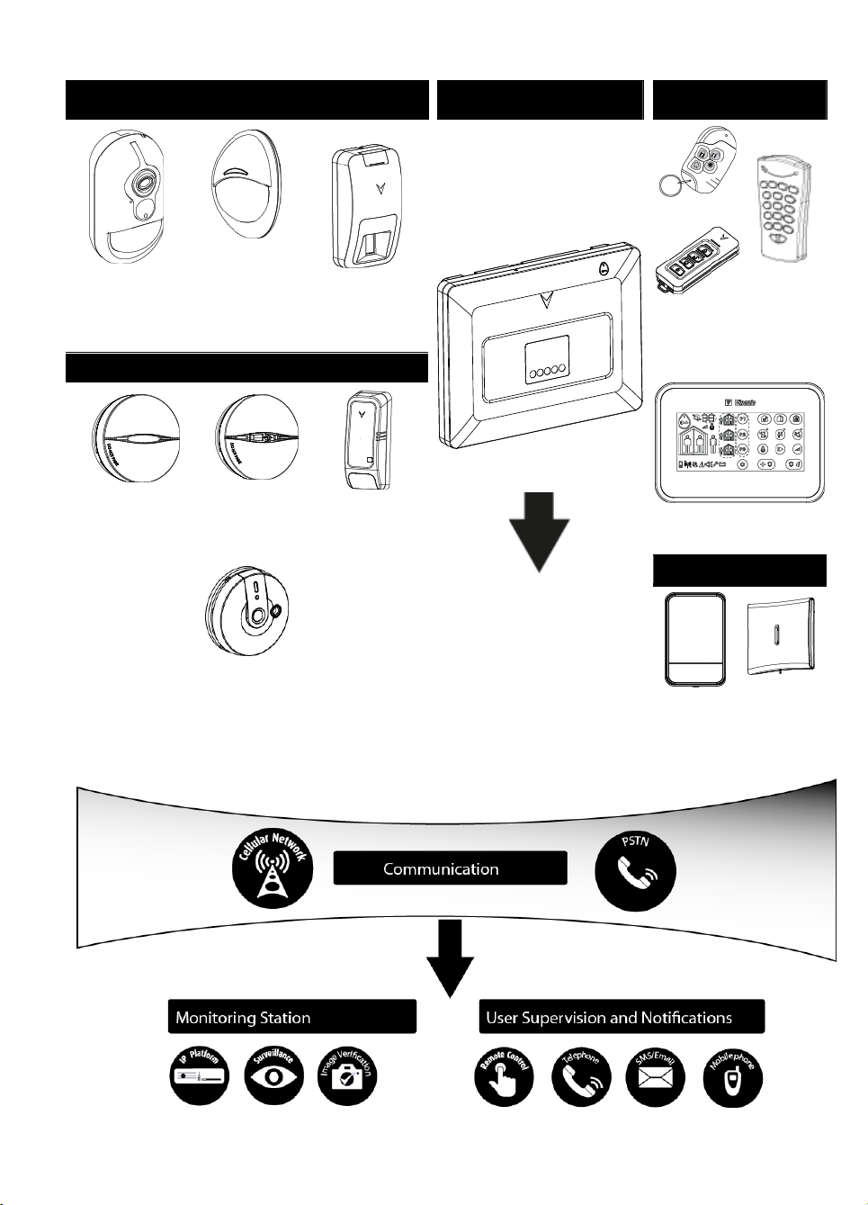
Security Detectors and Transmitters
Control Panel and Display
Keypad
Keyfobs, Keypad and
Keyprox
PGx9934
Motion Detector
with Camera
PGx9904
Motion Detector
PGx9974
Mirror Detector
WP8033
PGx9939
PGx9929
Two-way
Keyfobs
WK141
Two-way
Keypad
Safety Detectors
WK160 Keyprox
PGx9926 Smoke
Detector
PGx9916
Smoke & Heat
Detector
PGx9905
Temperature
Detector
PGx9913
Carbon Monoxide (CO) Detector
Sirens
PGx9911
Outdoor
Siren
PGx9901
Indoor Siren
System Architecture:
D-306048 WP8033 Installer's Guide 5
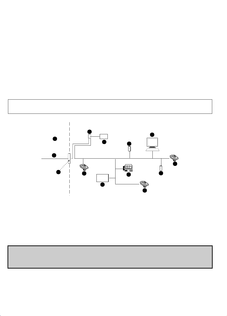
A. Network Service Provider's Facilities
F. Alarm Dialing Equipment
B. Telephone Line
G. Answering System
C. Network Demarcation Point
H. Unused RJ-11 Jack
D. RJ-31X Jack
I. Fax Machine
E. Telephone
J. Computer
A
B
C
D
E
F
G
H
I
E
E
H
J
2. CHOOSING THE INSTALLATION LOCATION
To ensure the best possible mounting location of the WP8033 control panel, the following points should be observed:
The selected location should be approximately in the center of the installation site between all the transmitters,
preferably in a hidden location.
In close proximity to an AC source
In close proximity to a telephone line connection (if PSTN is used)
Where there is good cellular coverage, if GSM-350 is used
Far from sources of wireless interference, such as:
o Computers or other electronic devices, power conductors, cordless phones, light dimmers, etc.
o Large metal objects (such as metal doors or refrigerators)
Note: A distance of at least 1 meter (3 ft) is recommended.
When mounting wireless devices:
Make sure that the signal reception level for each device is either "Strong" or "Good", but not "Poor".
Wireless magnetic contacts should be installed in a vertical position and as high up the door or window as possible.
Wireless PIR detectors should be installed upright at the height specified in their Installation Instructions
Repeaters should be located high on the wall in mid-distance between the transmitters and the control panel.
WARNING! To comply with FCC and IC RF exposure compliance requirements, the control panel should be located at
a distance of at least 20 cm from all persons during normal operation. The antennas used for this product must not be
co-located or operated in conjunction with any other antenna or transmitter.
Customer Premises Equipment and Wiring
Note: The REN is used to determine the number of devices that may be connected to a telephone line. Excessive RENs on a telephone line
may result in the devices not ringing in response to an incoming call. In most but not all areas, the sum of RENs should not exceed five (5.0).
To be certain of the number of devices that may be connected to a line, as determined by the total RENs, contact the local telephone
company.
Connection to telephone company provided coin service is prohibited. Connection to party lines service is subject to state tariffs.
The installer should verify line seizure. Be aware of other phone line services such as DSL. If DSL service is present on the
phone line, you must install a filter. It is suggested to use the DSL alarm filter model Z-A431PJ31X manufactured by
Excelsus Technologies, or equivalent. This filter simply plugs into the RJ-31X jack and allows alarm reporting without
breaking the internet connection.
6 D-306048 WP8033 Installer's Guide
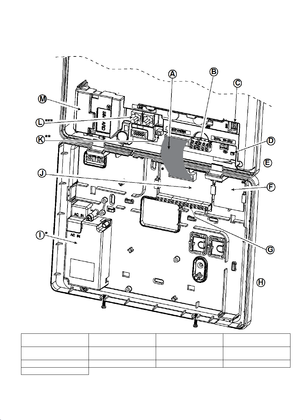
A. Expander Module Flat
Cable
B. Wired Zone / Special
Siren Terminal Block
C. Battery Connector
D. ENROLL button
E. Front Unit
F. Output Interface Module
G. Expander Module Wiring
Terminal Blocks
H. Back Unit
I. Power Supply
J. Expander Module
K. Power Connector
L. Phone Wiring Connectors
M. GSM-350
3. WP8033 INSTALLATION
Required tool: Philips screwdriver #2.
WP8033 mounting process is shown in Figures 3.1 - 3.10.
3.1 WP8033 Wiring Diagram
* or External Power Supply Unit
** or External Power Connector
*** or Terminal Block in North American Panels
D-306048 WP8033 Installer's Guide 7
Figure 3.1 – WP8033 Wiring Diagram
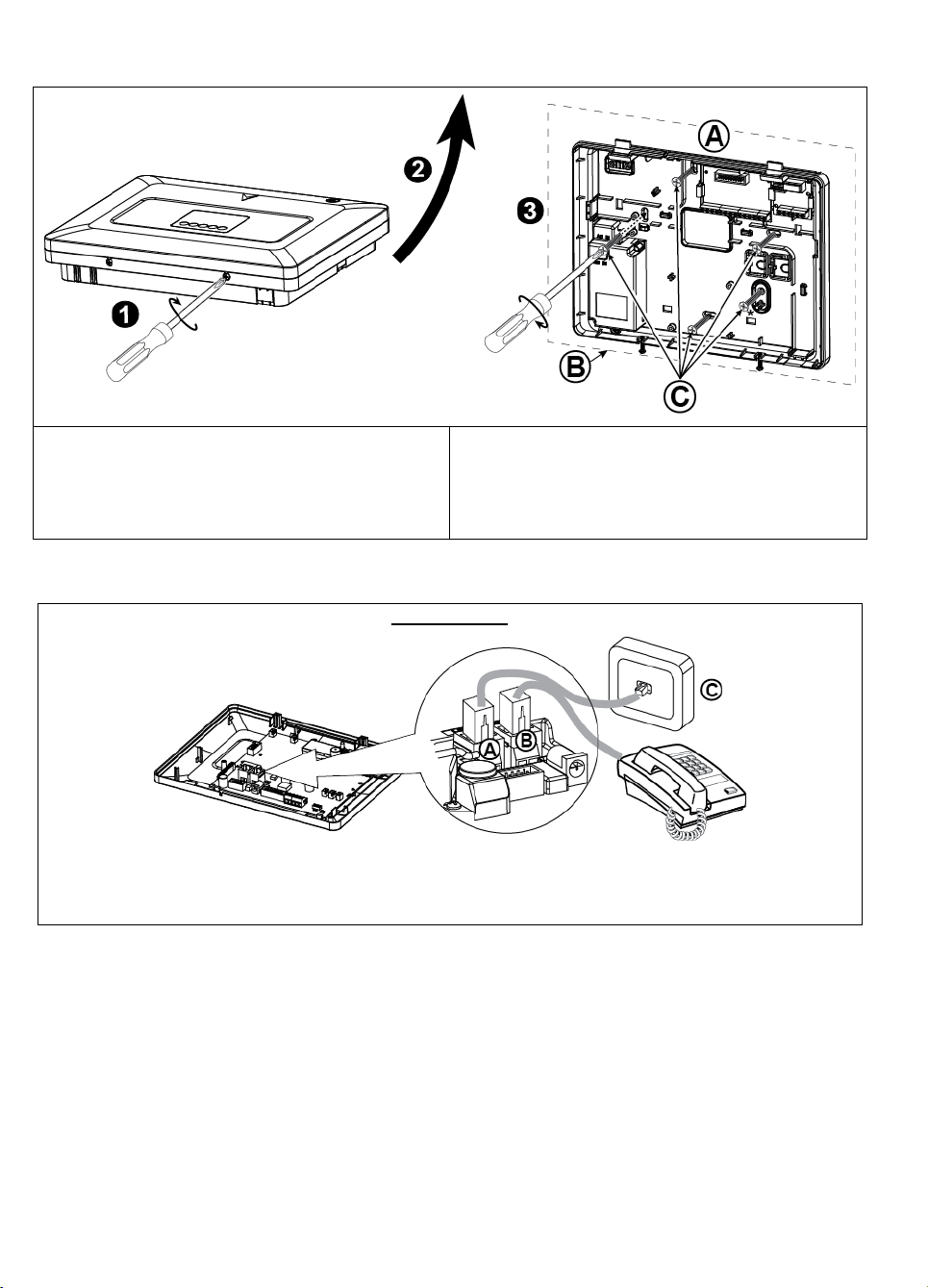
To Mount the Unit:
1. Release the screws
2. Remove the front cover
3. Mark 5 drilling points on the mounting surface, then
drill 5 holes and insert wall anchors and then fasten
the back unit with 4 screws
A. Mounting surface
B. Back unit
C. 5 screws
* For back tamper
PHONE WIRING
Connect the telephone cable to the SET connector and connect the telephone line cable to the LINE connector
(through the desired wiring cable entry).
Note: The telephone cable should be no longer than 3 meters.
A. LINE B. SET C. Tel line wall jack
3.2 Opening the WP8033 Control Panel and Bracket Mounting
Figure 3.2 – Back Unit Mounting
3.3 Connecting to the Telephone Line (detail "K" in Figure 3.1)
Figure 3.3 – Phone Wiring
If DSL service is present on the phone line, you must route the phone line through a DSL filter (refer to MESSAGE TO
THE INSTALLER on page 2 for further details).
8 D-306048 WP8033 Installer's Guide
 Loading...