

DSC WP8010, WP8030 Installer's Manual

WP8010/WP8030
Version 18
Installer's Guide
Table of Contents
1. INTRODUCTION ................................................. 3
1.1 System Features .......................................... 3
2. CHOOSING THE INSTALLATION LOCATION .. 6
3. WP8010 INSTALLATION .................................... 8
3.1 Opening the WP8010 Control Panel and
Bracket Mounting ............................................... 8
3.2 Connecting to the Telephone Line .............. 9
3.3 System Planning & Programming............. 10
3.4 GSM Module Installation ........................... 10
3.5 PGM-5 Installation ...................................... 11
3.6 Adding Wired Zones or PGM Device ........ 12
3.7 Connecting Power to the Control Panel ... 14
3.8 Supplying Power to the Unit ..................... 16
3.9 Closing the WP8010 Control Panel ........... 16
4. WP8010/WP8030 INSTALLATION ................... 17
4.1 WP8030 Wiring Diagram ............................ 17
4.2 Opening the WP8010/WP8030 Control Panel
and Bracket Mounting ..................................... 18
4.3 Connecting to the Telephone Line ............ 18
4.4 Connecting Wired Zone and Siren ............ 19
4.5 System Planning & Programming............. 19
4.6 GSM Module Installation ........................... 20
4.7 DUAL RS-232 Optional Module Mounting 21
4.8 PGM-5 Installation ...................................... 21
4.9 Optional Expander Module ........................ 22
4.10 Connecting Power to the Control Panel . 24
4.11 Battery Insertion....................................... 26
4.12 Supplying Power to the Unit ................... 26
4.13 Closing the WP8030 Control Panel ......... 27
5. PROGRAMMING .............................................. 28
5.1 General Guidance ...................................... 28
5.1.1 Navigation ................................ .......... 28
5.1.2 Feedback Sounds .............................. 29
5.2 Entering the "Installer Mode" and Selecting
a Menu Option .................................................. 29
5.2.1 Entering the "Installer Mode" if "User
Permit" is enabled ....................................... 30
5.2.2 Selecting options ................................ 30
5.2.3 Exiting the Installer Mode ................... 30
5.3 Setting Installer Codes ............................... 30
5.3.1 Identical Installer and Master Installer
Codes .......................................................... 31
5.4 Zones / Devices .......................................... 32
5.4.1 General Guidance & Zones/Devices
Menu Options .............................................. 32
5.4.2 Adding New Wireless Devices or Wired
Sensors ....................................................... 32
5.4.3 Deleting a Device ............................... 36
5.4.4 Modifying or Reviewing a Device ........ 37
5.4.5 Replacing a Device ............................. 37
5.4.6 Configuring Soak Test Mode .............. 38
5.4.7 Defining Configuration Defaults for
"Device Settings" ......................................... 38
5.4.8 Updating Devices after Exiting Installer
Mode ........................................................... 39
5.5 Control Panel .............................................. 39
5.5.1 General Guidance – "Control Panel"
Flow-Chart & Menu Options ........................ 39
5.5.2 Configuring Arming/Disarming and
Exit/Entry Procedures .................................. 40
5.5.3 Configuring Zones Functionality ......... 42
5.5.4 Configuring Alarms & Troubles ........... 42
5.5.5 Configuring Sirens Functionality ......... 44
5.5.6 Configuring Audible & Visual User
Interface ...................................................... 45
5.5.7 Configuring Jamming and Supervision
(Missing device) .......................................... 46
5.5.8 Configuring Miscellaneous Features ... 47
5.6 Communication .......................................... 48
5.6.1 General Guidance – "Communication"
Flow-Chart & Menu Options .......................... 48
5.6.2 Configuring PSTN (landline phone)
Connection .................................................. 49
5.6.3 Configuring GSM-GPRS (IP) - SMS
Cellular Connection ..................................... 50
D-306233 CUSDOC PM-10/30 V18 DSC TRIPLE EN INST 1

5.6.4 Configuring Events Reporting to
Monitoring Stations ..................................... 51
5.6.5 Configuring Events Reporting to Private
Users .......................................................... 55
5.6.6 Configuring Motion Cameras for Visual
Alarm Verification ........................................ 55
5.6.7 Configuring Upload / Download Remote
Programming Access Permission ............... 56
5.6.8 Broadband, ........................................ 58
5.7 PGM Output ................................................ 58
5.7.1 General Guidance .............................. 58
5.7.2 Open Collector States ........................ 58
5.7.3 PGM Output Configuration ................. 59
5.7.4 PGM-5 Connection............................. 60
5.7.5 Entering Daytime Limits ..................... 60
5.8 Custom Names ........................................... 61
5.8.1 Custom Zone Names ......................... 61
5.8.2 Record Speech .................................. 62
5.8.3 Voice Box Mode ................................. 63
5.9 Diagnostics ................................................. 63
5.9.1 General Guidance – "Diagnostics" Flow-
Chart & Menu Options ................................ 63
5.9.2 Testing Wireless Devices ................... 64
5.9.3 Testing the GSM module ................... 65
5.9.4 Testing the SIM Number .................... 66
5.9.5 Testing the Broadband/PowerLink
Module, ....................................................... 66
5.10 User Settings ............................................ 66
5.11 Factory Default ......................................... 67
5.12 Serial Number ........................................... 67
5.13 Partitioning ............................................... 67
5.13.1 General Guidance – "Partitioning"
Menu ........................................................... 67
5.13.2 Enabling / Disabling Partitions .......... 67
5.14 Operation Mode ........................................ 68
5.14.1 General Guidance – "Operation Mode"
Menu ........................................................... 68
5.14.2 Select setting ................................... 68
5.14.3 BS8243 Setup .................................. 68
5.14.4 DD243 Setup ................................... 69
5.14.5 CP01 Setup ...................................... 71
5.14.6 OTHERS Setup ................................ 72
6. PERIODIC TEST ............................................... 74
6.1 General Guidance ...................................... 74
6.2 Conducting a Periodic Test ....................... 74
7. MAINTENANCE ................................................ 77
7.1 Handling System Troubles ........................ 77
7.2 Dismounting the Control Panel ................. 78
7.3 Replacing the Backup Battery................... 78
7.4 Fuse Replacement ..................................... 78
7.5 Replacing/Relocating Detectors ................ 78
7.6 Annual System Check ................................ 79
8. READING THE EVENT LOG ............................. 80
APPENDIX A. Specifications ............................... 81
A1. Functional ................................................... 81
A2. Wireless ...................................................... 82
A3. Electrical ..................................................... 82
A4. Communication .......................................... 84
A5. Physical Properties ................................ .... 84
A6. Peripherals and Accessory Devices ......... 84
APPENDIX B. Working with Partitions ................ 86
B1. User Interface and Operation .................... 86
B2. Common Areas ........................................... 86
APPENDIX C. Detector Deployment & Transmitter
Assignments......................................................... 87
C1. Detector Deployment Plan ......................... 87
C2. Keyfob Transmitter List ............................. 88
C3. Emergency Transmitter List ...................... 88
C4. Non-Alarm Transmitter List ....................... 89
APPENDIX D. Event Codes .................................. 90
D1. Contact ID Event Codes ............................. 90
D2. SIA Event Codes ........................................ 90
D3. Understanding the Scancom Reporting
Protocol Data Format ....................................... 91
D4. SIA over IP - Offset for Device User .......... 91
APPENDIX E. Sabbath Mode ............................... 92
E1. General Guidance ....................................... 92
E2. Connection ................................................. 92
E3. Arming the System by Sabbath Clock ...... 92
APPENDIX F. PowerLink3 IP Communicator, ... 93
F1. Getting Started............................................ 93
F2. Specifications ............................................. 93
F3. Installation .................................................. 94
Package Contents ....................................... 94
System Requirements ................................. 94
F4. Installing the DSC PowerLink3
IP Communicator .............................................. 95
Hardware Installation ................................... 95
Control Panel Configuration ......................... 97
APPENDIX G. Glossary ........................................ 98
APPENDIX H. Compliance with Standards ........ 100
WP8010/WP8030 Quick User Guide .................. 102
2 D-306233 CUSDOC PM-10/30 V18 DSC TRIPLE EN INST

3. WP8010 INSTALLATION
Feature
Description
How to configure and use
Visual Alarm
Verification
The WP8010/WP8030 when used with
PG9934 PIR-camera detector and GPRS
communication is able to provide the
Monitoring Station with clips captured in
alarm situations. The system sends the clips
to the Monitoring Station automatically for
burglary alarms and, depending on setup,
also for fire and personal emergency alarms.
Note: WP8010/WP8030 is compatible with
the following UL/ULC listed receivers: SGSystem I, SG-System III, SG-System IV.
1. Setup GPRS communication: see GSM
Module Installation (section 3.4 for WP8010
or section 4.6 for WP8030).
2. Configure camera settings: refer to the
PG9934 Installation Instructions.
3. Enable fire and personal alarm
verification: see section 5.6.6 Configuring
Motion Cameras for Video Alarm Verification.
On demand clips from
cameras
The WP8010/WP8030 can provide images
from the PG9934 by demand from a remote
PowerManage server. Pictures are taken
based on a command from the monitoring
station. To protect customers' privacy, the
system can be customized to enable the "On
Demand View" only during specific system
modes (i.e. Disarm, Home & Away) and also
to a specific time window following an alarm
event.
1. Setup the On demand feature: see
section 5.6.6 Configuring Motion Cameras
for Video Alarm Verification.
2. To request and view images: refer to the
PowerManage User's Guide, Chapter 5
Viewing and Handling Events.
Easy Enrollment
PowerG devices are enrolled from the control
panel. "Pre-enrollment" can also be
performed by entering the PowerG device ID
number and then activating the device in the
vicinity of the panel.
To enroll or pre-enroll devices: see section
5.4.2 Adding New Wireless Devices or Wired
Sensors.
Device Configuration
Device parameters and related system
behavior can be configured from the control
panel or from a remote location.
Each PowerG device has its own settings
which can be configured through the control
panel by entering the "DEVICE SETTINGS"
menu.
Note: The minimum configuration of the
system includes one detector.
To configure devices from the control
panel: see Chapter 5 Programming and also
the individual device's Installation
Instructions.
To configure devices from a remote
location: refer to the PowerManage User's
Guide Chapter 3 Working with Panels and to
the Remote Programmer PC software User's
Guide, Chapters 6 and 7.
1. INTRODUCTION
WP8010WP8030 are PowerG-enabled professional all-in-one wireless security, fire and safety systems supporting
advanced applications and DSC's new revolutionary PowerG™ Two-Way, Time Division Multiple Access (TDMA) and
Frequency Hopping Spread Spectrum (FHSS) wireless technology. This offers unmatched wireless robustness,
superior range and long battery life; a perfect and user friendly solution for both monitoring service providers and
professional installers.
This manual refers to WP8010/WP8030 and above. The most updated manuals can be downloaded from the DSC
Web site http://www.dsc.com.
Note: For UL installations, please contact the manufacturer for the most recent version of UL approved documentation.
The WP8010/WP8030 control panel is supplied with 2 instruction manuals:
Installer's Guide (this manual) – for use of system installer during system installation and configuration
User’s Guide -– also for use of system installer during system installation and configuration, but also for the master
user of the system, once installation is completed. Hand over this manual to the master user of the system.
1.1 System Features
The following table lists the WP8010/WP8030 features with a description of each feature and how to use it.
D-306233 CUSDOC PM-10/30 V18 DSC TRIPLE EN INST 3

3. WP8010 INSTALLATION
Diagnostics of the
control panel and
peripherals
You can test the function of all wireless
sensors deployed throughout the protected
area, to collect information about the
received signal strength from each
transmitter and to review accumulated data
after the test.
To perform diagnostics and to obtain
signal strength indication: see section 5.9
Diagnostics.
Conducting periodic
tests
The system should be tested at least once a
week and after an alarm. The periodic test
can be conducted locally or from a remote
location (with the assistance from a nontechnical person in the house).
To conduct a walk test locally: see
Chapter 6 Periodic Test.
To conduct a walk test from remote
location: refer to the Remote Programmer
PC software User's Guide, Chapter 6 Data
Details Tables.
Partitions
The partitioning feature, when enabled,
divides your alarm system into distinct areas
each of which operates as an individual
alarm system. Partitioning can be used in
installations where shared security systems
are more practical, such as a home office or
warehouse building.
1. Enable partitioning: see section 5.13
Partitioning.
2. Setup partition association for each
device: see section 5.4.2 Adding New
Wireless Devices or Wired Sensors.
To understand more about partitioning:
see APPENDIX B. Working with Partitions
and APPENDIX B. in the User's Guide.
Two-way voice
communication1
The WP8010/WP8030 system enables voice
communication with Monitoring Stations.
To enable and configure two way voice:
see section 5.6.4 Configuring Events
Reporting to Monitoring Stations.
Device configuration
templates
The default parameters with which a new
device is enrolled into the system can be set
before you enroll devices. This default
template saves time on device configuration.
1. Define enrollment defaults for devices:
see section 5.4.7 Defining Configuration
Defaults for "Device Settings".
2. Enroll or pre-enroll devices: see section
5.4.2 Adding New Wireless Devices or Wired
Sensors.
SirenNet - distributed
siren using Smoke
detectors
All PowerG smoke detectors are able to
function as sirens, alerting on any of 4 types of
alarm in the system: fire, gas, burglary and
flood.
Note: For UL installations, smoke detectors
alert only upon fire alarm in the system.
Enable and configure SirenNet for each
smoke detector: refer to the (PGX926 /
PGX916.) Installation Instructions.
Integrated Siren built
into the panel
The control panel has a high-powered built-in
siren that sounds in case of alarm, enabled by
default.
To define whether or not the control
panel's siren will sound upon alarms: see
section 5.5.5 Configuring Sirens Functionality.
Wired Siren outputs
The control panel can operate a wired siren
and strobe devices.
Install and connect wired siren: see
section 4.9 Optional Expander Module
Mounting.
Wired zones and
programmable
outputs (PGM)
The control panel can support wired detectors
and control automation devices with
programmable wired outputs.
1. Connect a wired zone or PGM device:
see section 3.6 Adding a Wired Zone or
PGM.
2. Program the wired zone: see section
5.4.2 Adding New Wireless Devices or Wired
Sensors.
3. Program PGM outputs behavior: see
section 5.7 PGM Output.
1
Refers to WP8030 with voice option only
4 D-306233 CUSDOC PM-10/30 V18 DSC TRIPLE EN INST

3. WP8010 INSTALLATION
Reporting to Private
Users and/or
Monitoring Station by
telephone, SMS and
IP communication
The WP8010/WP8030 system can be
programmed to send notifications of alarm
and other events to 4 private telephone
subscribers by voice and also to 4 SMS
cellular phone numbers and to report these
events to the Monitoring Station by SMS,
PSTN or IP communication
(IP communication not enabled in UL Listed
product).
To configure notifications to Private
phones: refer to the WP8010/WP8030-
User's Guide, Chapter 6, section B.12
Programming Private Phone and SMS
Reporting.
To configure reporting to the Monitoring
Station: see section 5.6.4 Configuring
Events Reporting to Monitoring Stations.
Quick installation with
link quality indication
With PowerG devices, there is no need to
consult the control panel when mounting a
wireless device, because PowerG devices
include a built-in link quality indicator.
Choosing the mounting location is a quick
and easy process.
To choose the ideal location to mount a
wireless device, see Chapter 2 Choosing the
Installation Location.
Device Locator
Helps you to easily identify the actual device
displayed on the LCD display.
To read more on the Device Locator: refer
to the WP8010/WP8030 User's Guide,
Chapter 2, Operating the WP8010/WP8030
System.
To use the device locator when bypassing
a zone or when clearing a bypassed zone:
refer to the WP8010/WP8030 User's Guide,
Chapter 6, section B.1 Setting the Zone
Bypass Scheme.
To use the device locator when
conducting the periodic test: see Chapter
6 Periodic Test or refer to the
WP8010/WP8030 User's Guide, Chapter 9
Testing the System.
Guard key-safe
WP8010/WP8030 is able to control a safe
that holds site keys that are accessible only
to the site's guard or Monitoring Station's
guard in the event of an alarm.
1. Connect the safe to the panel: see
section 3.6 Adding Wired Zones or PGM
Device, Figure 3.6b (WP8010) / section 4.9
Optional Expander Module Mounting, Figure
4.9b (WP8030).
2. Configure the safe's zone type to
"Guard Zone": see section 5.4.2 Adding
New Wireless Devices or Wired Sensors.
3. Setup guard code: see section 5.3
Setting Installer Codes.
Arming Key
External system may control arming and
disarming of the WP8010/WP8030 system.
1. Connect the external system output to
the panel: see section 3.6 Adding Wired
Zones or PGM Device, Figure 3.6b
(WP8010) / section 4.9 Optional Expander
Module Mounting, Figure 4.9b (WP8030).
Note: Monitoring Station means not evaluated by UL.
D-306233 CUSDOC PM-10/30 V18 DSC TRIPLE EN INST 5
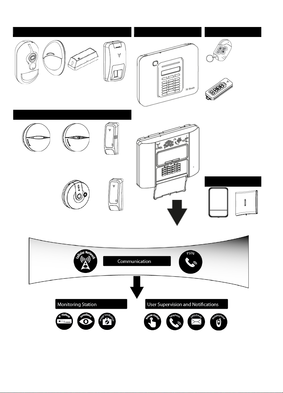
3. WP8010 INSTALLATION
Security Detectors and Transmitters
Main Control Panels
Keyfobs, Keypads, Keyprox
PGX934Moti
on Detector
with Camera
PGX904Moti
on Detector
PGX935Magn
etic Shock
and Contact
Detector
PGX974
Mirror Motion
Detector
WP8010
WP8030
PGX939
Wireless Key
PGX299
Wireless Key
Safety Detectors
PGX916 Smoke and
Heat Detector
PGX926
Smoke
Detector
PGX905
Temperature
Detector
PGX913
Carbon Monoxide (CO)
Detector
PGX985Flood
Detector
Sirens
PGX911Out
door Siren
PGX901
Indoor Siren
System Architecture:
2. CHOOSING THE INSTALLATION LOCATION
To ensure the best possible mounting location of the WP8010/WP8030 control panel, the following points should be
observed:
The selected location should be approximately in the center of the installation site between all the transmitters,
preferably in a hidden location.
6 D-306233 CUSDOC PM-10/30 V18 DSC TRIPLE EN INST

In close proximity to an AC source
A. Network Service Provider's Facilities
F. Alarm Dialing Equipment
B. Telephone Line
G. Answering System
C. Network Demarcation Point
H. Unused RJ-11 Jack
D. RJ-31X Jack
I. Fax Machine
E. Telephone
J. Computer
A
B
C
D
E
F
G
H
I
E
E
H
J
3. WP8010 INSTALLATION
In close proximity to a telephone line connection (if PSTN is used)
Where there is good cellular coverage, if GSM-350 PG2 is used
Far from sources of wireless interference, such as:
o Computers or other electronic devices, power conductors, cordless phones, light dimmers, etc.
o Large metal objects (such as metal doors or refrigerators)
Note: A distance of at least 1 meter (3 ft.) is recommended.
If using the panel's built-in siren and/or voice, select location where audio can be heard throughout the premises.
When mounting wireless devices:
Make sure that the signal reception level for each device is either "Strong" or "Good", but not "Poor".
Note: For UL/cUL installations, the test result must be "Strong" for all wireless devices.
Wireless magnetic contacts should be installed in a vertical position and as high up the door or window as possible.
Wireless PIR detectors should be installed upright at the height specified in their Installation Instructions
Repeaters should be located high on the wall in mid-distance between the transmitters and the control panel.
WARNING! To comply with FCC and IC RF exposure compliance requirements, the control panel should be located at
a distance of at least 20 cm from all persons during normal operation. The antennas used for this product must not be
co-located or operated in conjunction with any other antenna or transmitter.
Customer Premises Equipment and Wiring
Note: The REN is used to determine the number of devices that may be connected to a telephone line. Excessive RENs on a telephone line
may result in the devices not ringing in response to an incoming call. In most but not all areas, the sum of RENs should not exceed five (5.0).
To be certain of the number of devices that may be connected to a line, as determined by the total RENs, contact the local telephone
company.
Connection to telephone company provided coin service is prohibited. Connection to party lines service is subject to state tariffs.
The installer should verify line seizure. Be aware of other phone line services such as DSL. If DSL service is present on the
phone line, you must install a filter. It is suggested to use the DSL alarm filter model Z-A431PJ31X manufactured by
Excelsus Technologies, or equivalent. This filter simply plugs into the RJ-31X jack and allows alarm reporting without
breaking the internet connection.
D-306233 CUSDOC PM-10/30 V18 DSC TRIPLE EN INST 7
3. WP8010 INSTALLATION
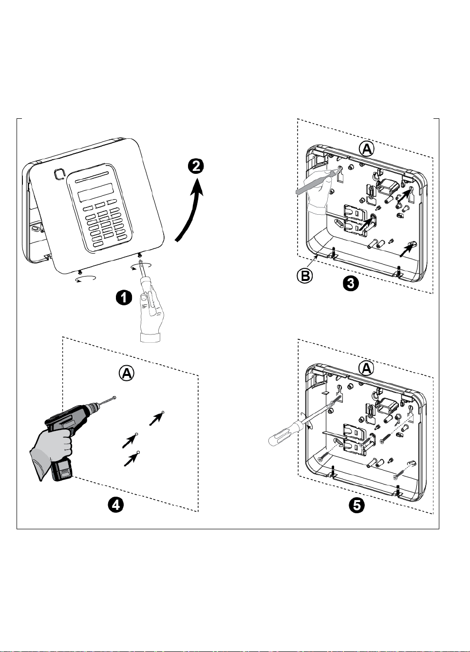
Figure 3.1 – Back Unit Mounting
To Mount the Unit:
1. Release the screws
A. Mounting surface
2. Remove the front cover
B. Back unit
3. Mark 4 drilling points on the mounting surface
4. Drill 4 holes and insert wall anchors
5. Fasten the back unit with 4 screws
3. WP8010 INSTALLATION
Required tool: Philips screwdriver #2.
WP8010mounting process is shown in Figures 3.1 - 3.9.
3.1 Opening the WP8010Control Panel and Bracket Mounting
WARNING! When plugging SIREN & ZONE terminals back into place, be sure to align them carefully with the pins on the
PCB. Misaligned or reverse insertion of terminals may cause internal damage to the WP8010!
8 D-306233 CUSDOC PM-10/30 V18 DSC TRIPLE EN INST
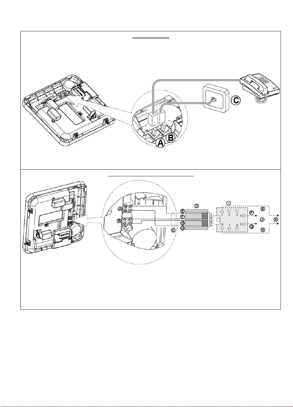
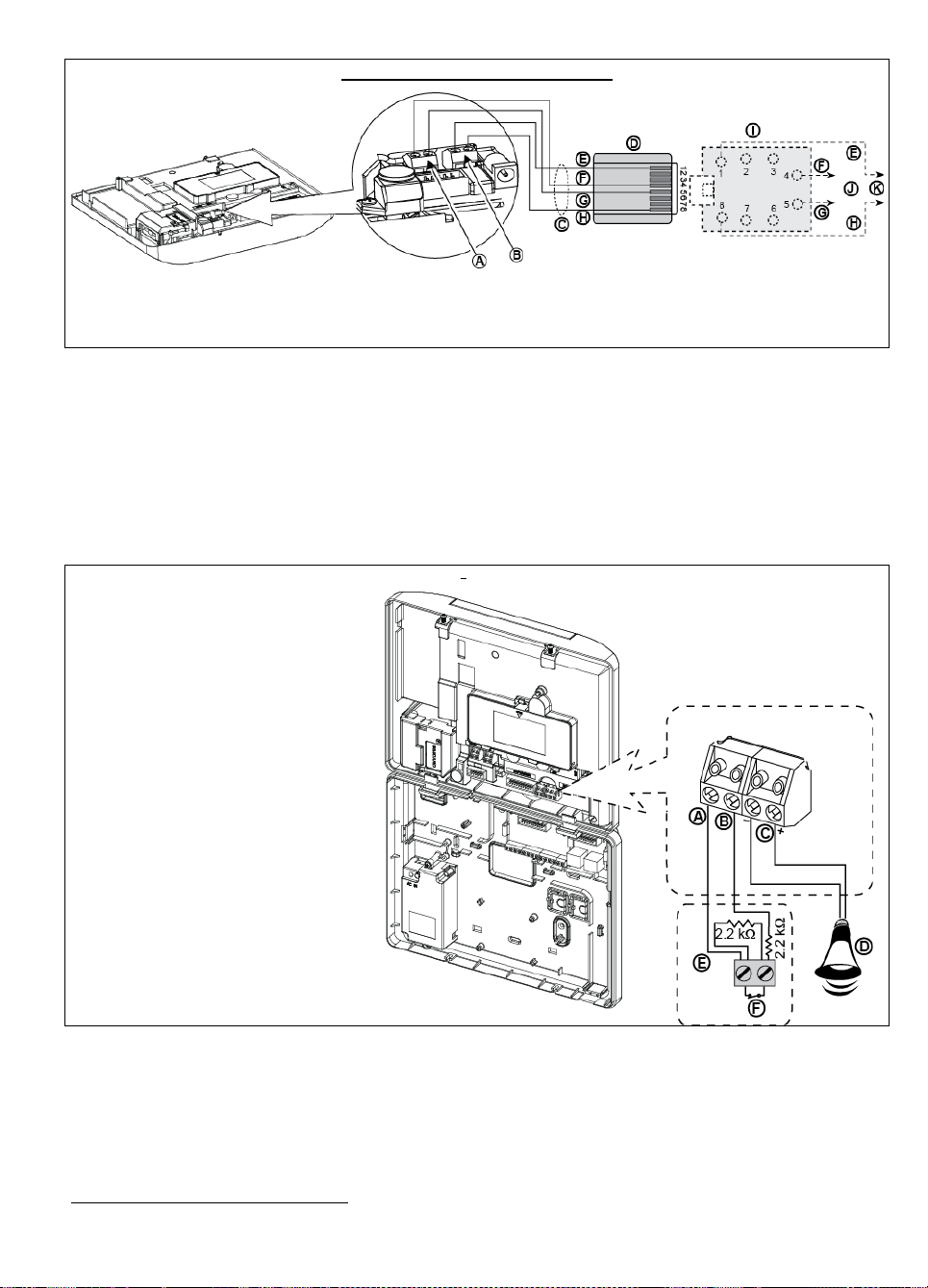
3.2 Connecting to the Telephone Line
PHONE WIRING
Connect the telephone cable to the SET connector and connect the telephone line cable to the LINE connector
(through the desired wiring cable entry).
Notes:
1. The telephone cable should be no longer than 3 meters.
2. For UL installations, the telephone cable must be no less than 26 AWG.
A. SET
B. LINE
C. Tel line wall jack
PHONE WIRING IN NORTH AMERICA
A. SET
G. Green
B. LINE
H. Brown
C. RJ-31X cord
I. RJ-31X jack
D. 8-position RJ-31X plug
J. Line from street
E. Gray
K. House phones
F. Red
3. WP8010 INSTALLATION
Figure 3.2 –Phone Wiring
This equipment is designed to be connected to the telephone network using an RJ11 connector which complies with
Part 68 rules and requirements adopted by ACTA and a properly installed RJ31X connector. See drawing above for
details.
In the case that RJ31X is not available (consult your telephone company or a qualified installer), the telephone line
should be connected to the WP8010unit first and then all other home equipment should be connected to the
WP8010"Phone" outlet.
D-306233 CUSDOC PM-10/30 V18 DSC TRIPLE EN INST 9
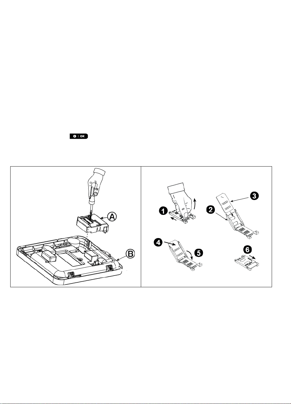
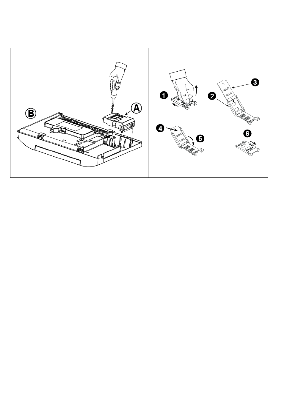
3. WP8010 INSTALLATION
Plug in the GSM module and fasten it as shown in the
above drawing.
A. GSM
B. Front unit
Caution! Disconnect both batteries and AC power before
installing or removing the GSM module or SIM card.
Insert the SIM card into the GSM module as shown in the
above drawing.
1. Slide top cover.
2. Open cover
3. Align SIM card in cover (note cover orientation)
4. Slide SIM card into cover
5. Rotate cover to close
6. Lock cover to close
IMPORTANT! Do not insert or remove SIM card when the
control panel is powered by AC power or battery.
3.3 System Planning & Programming
Program the system now as instructed in the programming section.
The tables in APPENDIX C will help you plan and record location of each detector, the holder and assignment of each
transmitter.
3.4 GSM Module Installation
The internal GSM 350 module enables the WP8010system to operate over a GSM/GPRS cellular network (for further
details, see the GSM 350 PG2 Installation Instructions).
The GSM modem auto detection feature enables automatic enrollment of the GSM modem into the WP8010 control
panel memory. GSM modem auto detection is activated in one of two ways: after tamper restore and after reset
(power-up or after exiting the installer menu). This causes the WP8010 to automatically scan GSM COM ports for the
presence of the GSM modem.
In the event that the GSM modem auto detection fails and the modem was previously enrolled in the WP8010G2
control panel, the message "Cel Remvd Cnfrm" will be displayed. This message will disappear from the display only
after the user presses the button. The modem is then considered as not enrolled and no GSM trouble
message will be displayed.
Note:
A message is displayed only when the WP8010alarm system is disarmed.
10 D-306233 CUSDOC PM-10/30 V18 DSC TRIPLE EN INST
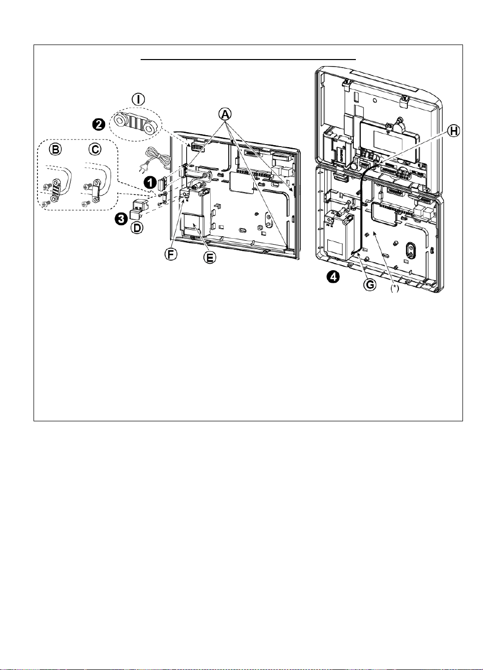
Figure 3.4 – Optional GSM Module Mounting and SIM Card Insertion
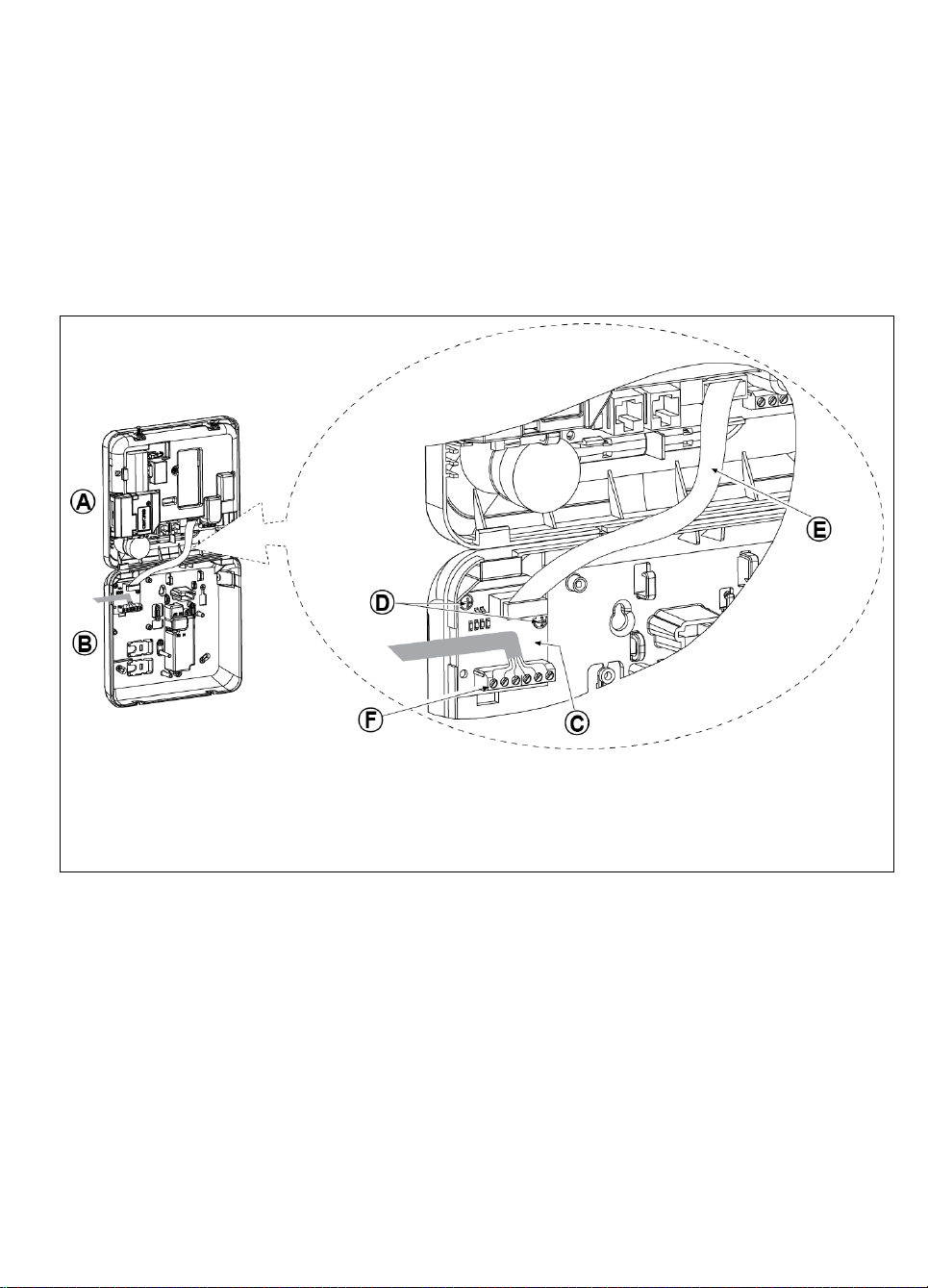
3. WP8010 INSTALLATION
A. Front unit
B. Back unit
C. PGM-5 Module
D. 2 Screws for fastening the PGM-5 Module
E. Flat cable
F. Wiring
3.5 PGM-5 Installation
PGM-5 is an output interface module designed to provide alarm, trouble events and status signals to external devices
such as long range wireless monitoring transmitters, CCTV systems, home-automation systems and LED annunciation
panels (for further details see the PGM-5 Installation Instructions).
The PGM-5 provides 5 solid state relay contact outputs and is designed to be used as a plug-in internal add-on module
with the WP8010control panel.
Notes:
1. The PGM-5 will be active only if the PGM-5 option was enabled in the factory default of the control panel.
2. PGM-5 plug-in module not enabled in UL Listed product.
Caution! When mounting the PGM-5 module it is strongly recommended to route the cable as shown in Figure 3.5 to
prevent interference which may occur if routed too close to the control panel antennas.
D-306233 CUSDOC PM-10/30 V18 DSC TRIPLE EN INST 11
Figure 3.5 – PGM-5 Module Mounting
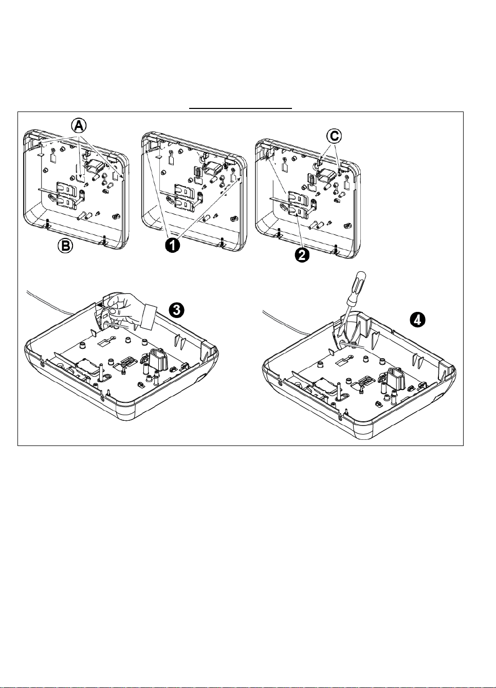
3. WP8010 INSTALLATION
A. Cables entry
options
B. Back unit
C. Cable clips
To Route the Cable:
1. Remove the left or
right side cables
entry knockout(s)
and enter the
required cable(s)
2. Remove and use as
cable clamp(s)
3.6 Adding Wired Zones or PGM Device
Required tools: Cutter and slotted screwdriver - 3 mm blade.
WP8010wiring is shown in Figures 3.6a – 3.7b.
CABLES ROUTING GUIDE
To Route the Cable (continued):
3. Position the clamp (1 of 2) as shown and then rotate into place.
4. Using a slotted screwdriver press downward gently on the point illustrated in the drawing. Make sure the clamp is
locked (a click is heard).
Figure 3.6a – Cable Wiring
12 D-306233 CUSDOC PM-10/30 V18 DSC TRIPLE EN INST
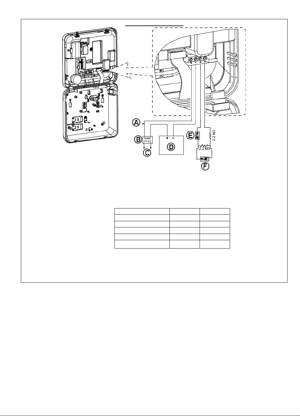
PGM AND ZONE WIRING
A. PGM output
Vmax=30v
Imax=100mA
B. Relay
C. Device
D. External power supply 5 -
30VDC
E. Wired detector's Tamper
F. Wired detector's alarm or
Arming Key (see section
5.4.2, “Zone Type List”
table).
For UL installations, D and E
must be UL listed.
PGM: not to be enabled in UL
listed product.
Note:
The wired detector should be installed at least 2 meters away from the
control panel.
Regarding the wired zone, the control panel classifies the events according
to the resistance it measures as shown in the table below.
E.O.L or Arming Key Resistance
Range
Zone
Arming Key
0 kΩ 1.76 kΩ
Tamper
Tamper
1.76 kΩ 2.64 kΩ
Normal
Arm
2.64 kΩ 3.52 kΩ
Tamper
Tamper
3.52 kΩ 5.26 kΩ
Alarm
Disarm
5.26 kΩ ∞
Tamper
Tamper
Notes:
1. The E.O.L resistors are 2.2 kΩ resistors of 1/4 W, 5% supplied with the
panel and are UL listed under the name EOLR-3, kit number 57000850.
2. If the Arming Key is enabled, the wired zone must be located in the
protected area.
3. WP8010 INSTALLATION
Figure 3.6b – PGM & Zone Wiring
Notes for UL installations:
1. A device that is connected to PGM terminal should not be programmed to be activated during standby.
2. The system shall be installed in accordance with CSA C22.1 Canadian Electrical Code, Part 1.
3. A minimum spacing of 1/4 inch shall be maintained between the telephone wiring and the low voltage wiring (zones,
bell circuit, etc.). Do not route the LINE and SET wires in the same wiring channel with other wires.
4. Do not connect to a receptacle controlled by a switch.
5. Hard wired zones are for BURG use only.
6. Tamper (E) must be UL Listed.
7. Minimum System Configuration for BURG consists of: Control Panel (WP8010 or WP8030). Intrusion Detection
Device (Magnetic Contact, PIR, Wired Zone etc.) compatible UL Listed Monitoring Station Receiver.
8. Minimum System Configuration for FIRE consists of: Control Panel (WP8010or WP8030). Zone etc, Smoke
Detector (SMD-426/427 PG2), compatible UL Listed Monitoring Station Receiver.
D-306233 CUSDOC PM-10/30 V18 DSC TRIPLE EN INST 13
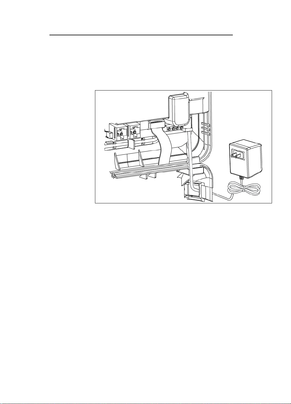
3. WP8010 INSTALLATION
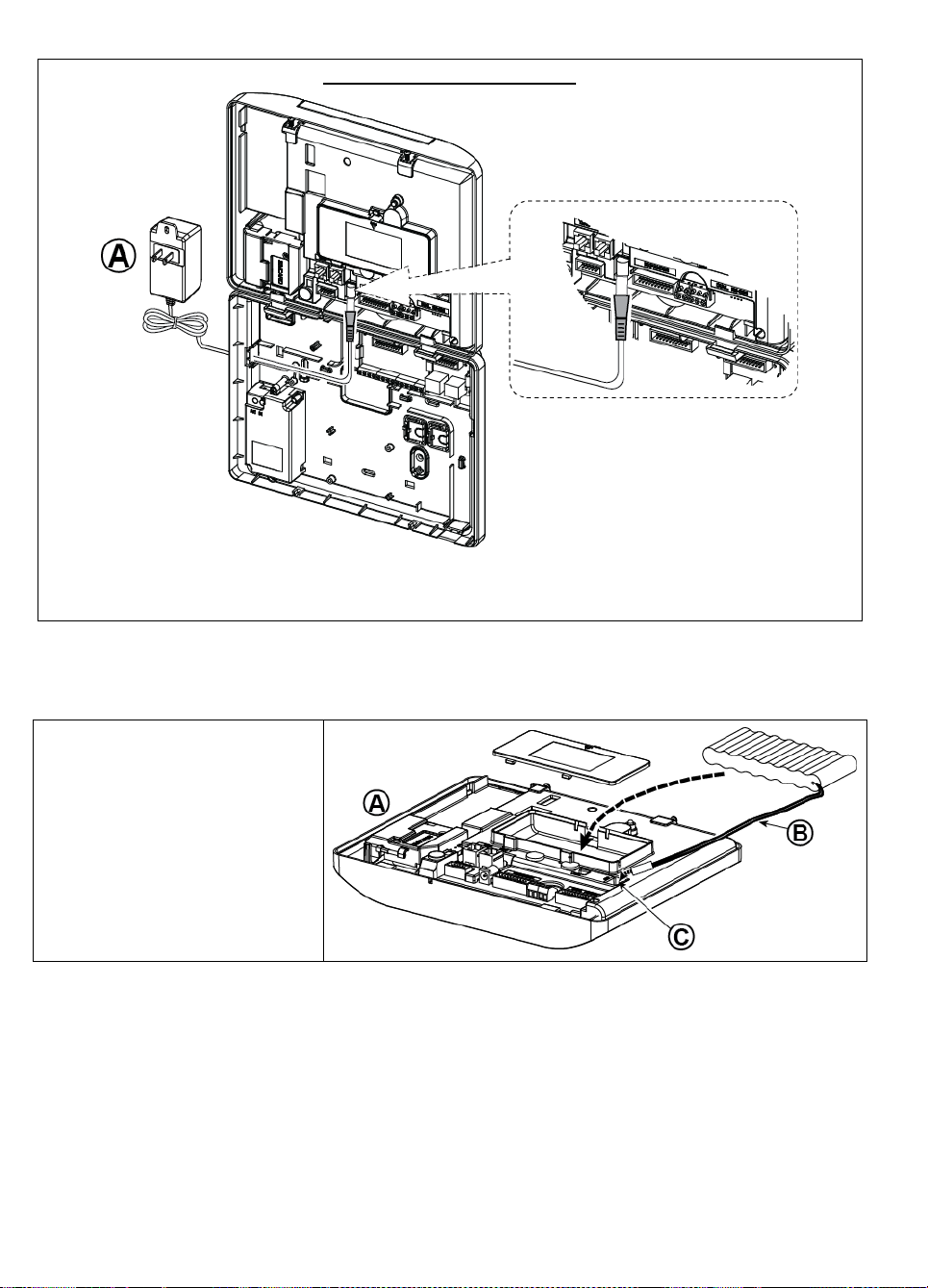
Connect the power adapter to the
power connector.
Figure 3.7a - Power Cable
Connection
3.7 Connecting Power to the Control Panel
CONNECTING AC POWER TO CONTROL PANEL USING AC/AC TRANSFORMER
Connect the power cable and close the control panel as shown below.
Notes:
1) Do not use mains cable (3 m long) or power supply other than that supplied by the manufacturer DONGGUAN
ORIENTAL HERO ELE. CO. LTD., model no. OH-41111AT-2.
2) For UL installations (UL), the plug-in transformer must have restraining means. For Canada (CUL), it cannot have
restraining means.
Note: This equipment should be installed in accordance with Chapter 2 of the National Fire Alarm Code, ANSI/NFPA 72 and
CAN/ULC-S540.
14 D-306233 CUSDOC PM-10/30 V18 DSC TRIPLE EN INST
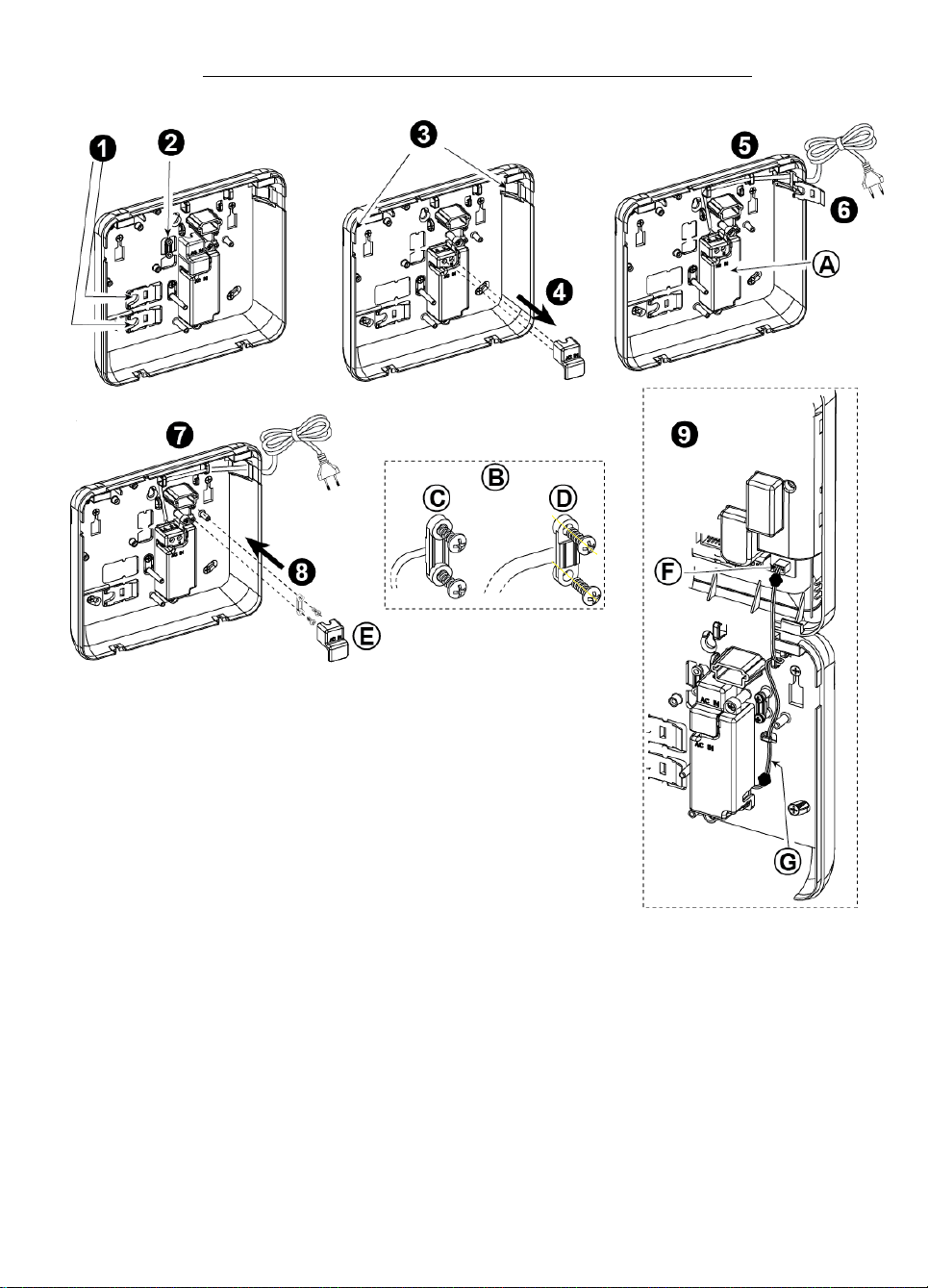
3. WP8010 INSTALLATION
1. Extract either plastic segment (will be used later)
7. Fasten power cable by clamp (extracted in step 2)
2. Extract plastic segment (will be used later)
8. Close power supply terminals cover
3. Knock out the plastic segment (left or right, according
to the power wiring direction)
9. Connect the DC output cable plug into the DC input
socket located on the front panel.
4. Remove power supply terminals cover (E)
A. Internal AC/DC power supply unit
B. Power cable clamp options
C. For thin cable
D. For thick cable (reversed clamp)
E. Terminals cover
F. DC input socket on front panel
G. DC output cable
5. Insert the power cable through the desired wiring
channel, route it to the power supply unit and connect
its 2 wires to the power supply terminal block with a
screwdriver. Fasten the screws tightly.
Verify that the wires are properly fastened!
6. Insert plastic cap to the power cable entry (extracted
in step 1)
CONNECTING AC POWER USING INTERNAL AC/DC POWER SUPPLY UNIT
PERFORM STEPS 1 and 2 ON A WORKBENCH BEFORE THE MOUNTING
D-306233 CUSDOC PM-10/30 V18 DSC TRIPLE EN INST 15
Figure 3.7b – Power Cable Wiring
3. WP8010 INSTALLATION
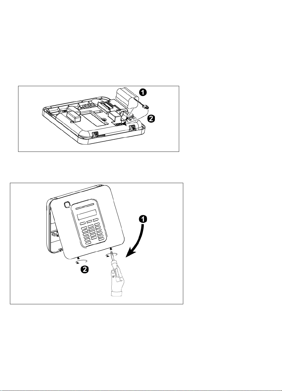
Figure 3.8 – Connecting Power to the Control Panel
Inserting Backup Battery:
Connect battery pack as shown in
Figure 3.8.
1. Insert battery
2. Connect the battery
Figure 3.9 - Final Closure
To Close the Control Panel:
1. Close the front cover
2. Fasten the screws
3.8 Supplying Power to the Unit
Connect power to the WP8010temporarily (see Figure 3.7a). Alternatively, you may power up from the backup battery,
as shown in Figure 3.8.
Disregard any “trouble” indications pertaining to lack of battery or lack of telephone line connection.
For Europe Safety Compliance:
a. The model shall be installed according to the local electrical code.
b. The circuit breaker shall be readily accessible.
c. The rating of the external circuit breaker shall be 16A or less.
d. The cables for the AC mains connection shall have an overall diameter of 13mm and 16mm conduit.
Please refer to Figure 3.7a "Power Cable Connection".
3.9 Closing the WP8010Control Panel
Control panel final closure is shown below.
16 D-306233 CUSDOC PM-10/30 V18 DSC TRIPLE EN INST
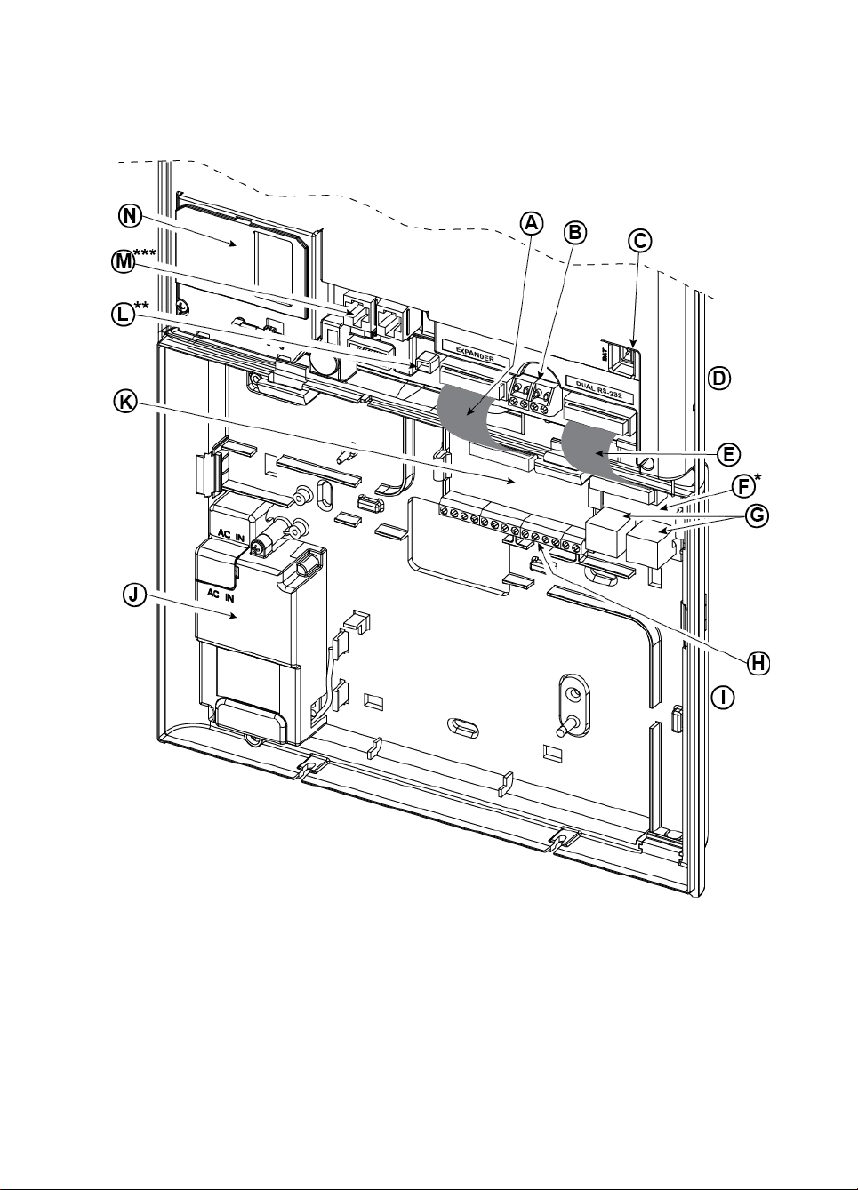
4. WP8030INSTALLATION
A. Expander Module Flat
Cable
B. Wired Zone / Special
Siren Terminal Block
C. Battery Connector
D. Front Unit
E. Dual RS-232 Module Flat
Cable
F. Dual RS-232 Module
G. Dual RS-232 Module
Connectors
H. Expander Module Wiring
Terminal Blocks
I. Back Unit
J. Power Supply
K. Expander Module
L. Power Connector
M. Phone Wiring
Connectors
N. GSM-350 PG2
Required tool: Philips screwdriver #2.
WP8030 mounting process is shown in Figures 4.1 - 4.13.
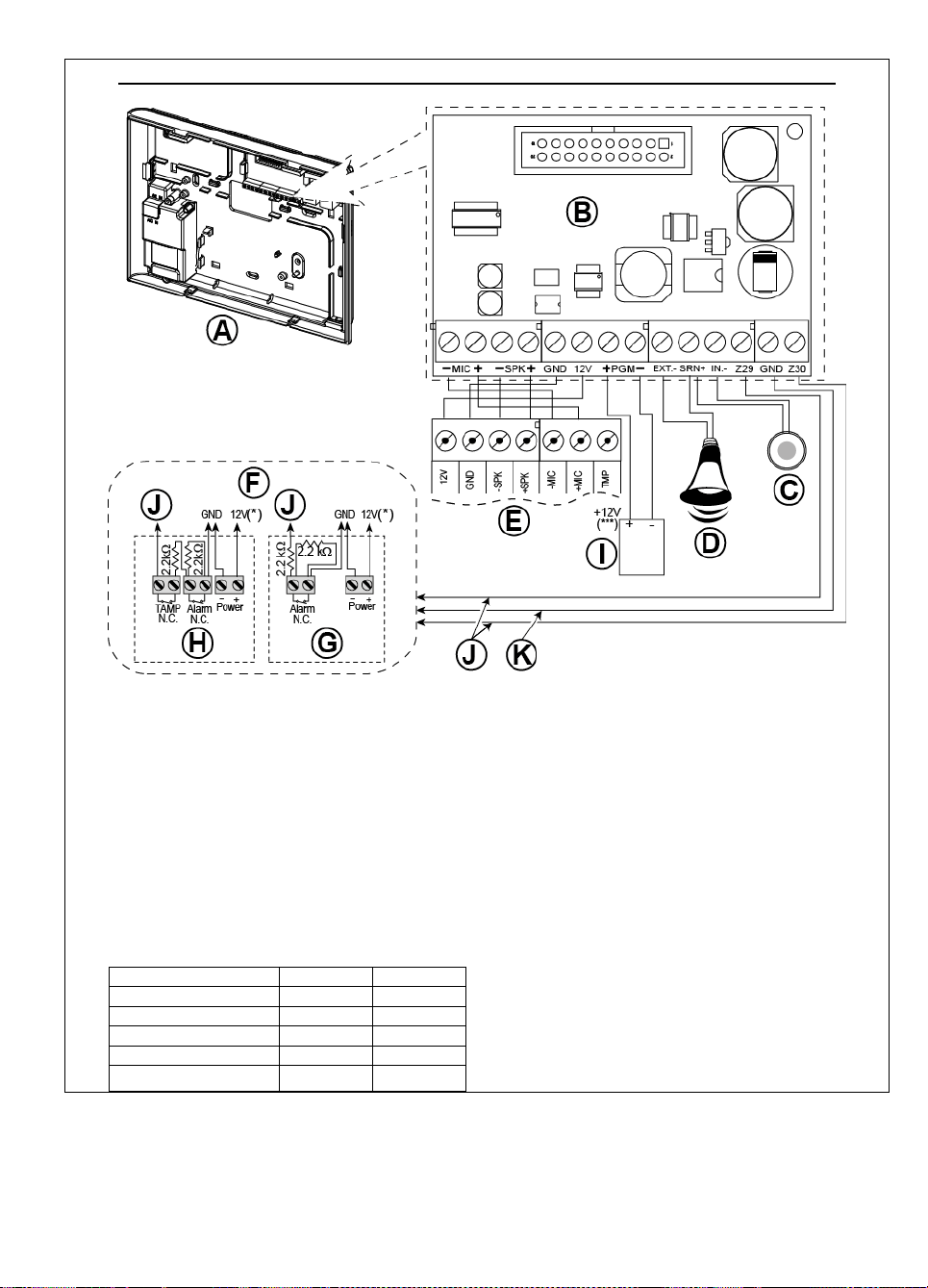
4.1 WP8030Wiring Diagram
3. WP8010 INSTALLATION
* or PGM-5 Module
** or External Power Connector
*** or Terminal Block in North American Panels
D-306233 CUSDOC PM-10/30 V18 DSC TRIPLE EN INST 17
Figure 4.1 – WP8030Wiring Diagram
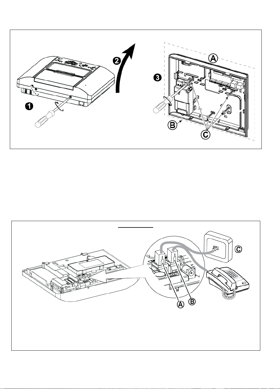
3. WP8010 INSTALLATION
To Mount the Unit:
1. Release the screws
2. Remove the front cover
3. Mark 4 drilling points on the mounting surface, then
drill 4 holes and insert wall anchors and then fasten
the back unit with 4 screws
A. Mounting surface
B. Back unit
C. Screws
PHONE WIRING
A. LINE B. SET C. Tel line wall jack
Connect the telephone cable to the SET connector and connect the telephone line cable to the LINE connector
(through the desired wiring cable entry).
Notes:
1. The telephone cable should be no longer than 3 meters.
2. For UL installations, the telephone cable must be no less than 26 AWG.
4.2 Opening the WP8030Control Panel and Bracket Mounting
Figure 4.2 – Back Unit Mounting
4.3 Connecting to the Telephone Line
(detail "M" in Figure 4.1)
18 D-306233 CUSDOC PM-10/30 V18 DSC TRIPLE EN INST
Figure 4.3a – Phone Wiring
3. WP8010 INSTALLATION
PHONE WIRING IN NORTH AMERICA
A. LINE
B. SET
C. RJ-31X cord
D. 8-position RJ-31X plug
E. Brown
F. Red
G. Green
H. Gray
I. RJ-31X jack
J. Line from street
K. House phones
WIRED ZONE1 &SIREN WIRING
A. GND
B. Wired Zone
C. Siren*
D. Site external siren MG electronics
MG441PDS or equivalent 612VDC, 150 mA Max*
E. Magnetic contact or any other
contact (not a detector)
F. Alarm N.C.
*Not to be used in UL Listed Product
1
Figure 4.3b – Phone Wiring in North America
Phone wiring in the UK: Line terminals must be connected to pins 2 and 5 of the wall jack.
For all installations: If DSL service is present on the phone line, you must route the phone line through a DSL filter
(refer to MESSAGE TO THE INSTALLER on page 2 for further details).
4.4 Connecting Wired Zone and Siren
(detail "B" in Figure 4.1)
If an expander module is not used, one wired zone and one low voltage siren can be connected directly to the front
panel PCB (not allowed in UL installations).
4.5 System Planning & Programming
Program the system now as instructed in the programming section.
The tables in APPENDIX C will help you plan and record the location of each detector, the holder and assignment of
each transmitter.
Wired zones can be enrolled in any zone in the WP8030 control panel from 01 to 64
D-306233 CUSDOC PM-10/30 V18 DSC TRIPLE EN INST 19
Figure 4.4 – Wired Zone and Siren Wiring
3. WP8010 INSTALLATION
Plug in the GSM module and fasten it as shown in the above
drawing.
A. GSM
B. Front unit
Caution! Do not install or remove the GSM module when the
system is powered by AC power or backup battery.
Insert the SIM card into the GSM module as shown in
the above drawing.
1. Slide top cover.
2. Open cover
3. Align SIM card in cover (note cover orientation)
4. Slide SIM card into cover
5. Rotate cover to close
6. Lock cover to close
IMPORTANT! Do not insert or remove SIM card when
the control panel is powered by AC power or battery.
4.6 GSM Module Installation
(detail "N" in Figure 4.1)
Figure 4.6
20 D-306233 CUSDOC PM-10/30 V18 DSC TRIPLE EN INST
– Optional GSM Module Mounting and SIM Card Insertion

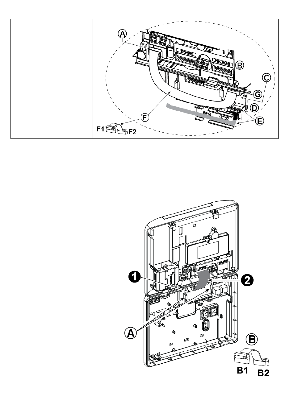
3. WP8010 INSTALLATION
1. To install the DUAL RS-232 module into
the control panel, press it into the
marked location (see Figure 4.7) until a
click is heard.
2. Connect the flat cable (included in the
module's package) between the front
panel and the DUAL RS-232 receptacle.
Caution! The receptacle with strain
relief clip is for the front unit – do not
connect it to the back unit!
3. Connect a local PC to the DUAL RS-
232 module connector (B) or (C), as
shown in Figure 4.7.
A. DUAL RS-232 Module
B. Connector for PC
C. Connector for PC
D. DSC PC cable
E. Flat cable with one strain relief clip
E1. This side for front unit
E2. This side for back unit
F. Flat cable connector
4.7 DUAL RS-232 Optional Module Mounting
(detail "F" in Figure 4.1)
The Dual RS-232 is a module that enables connection of any two simultaneous devices, such as Local PC
programming or GSM Module.
The GSM unit enables the WP8030system to operate over a cellular network (for details regarding the GSM modem
features and connections, refer to the GSM Modem installation instructions).
Note: The Dual RS-232 Module is not to be connected in UL Listed product.
4.8 PGM-5 Installation
(located instead of detail "F" in Figure 4.1)
PGM-5 is an output interface module designed to provide alarm, trouble events and status signals to external devices
such as long range wireless monitoring transmitters, CCTV systems, home-automation systems and LED annunciation
panels (for further details see the PGM-5 Installation Instructions).
The PGM-5 provides 5 solid state relay contact outputs and is designed to be used as a plug-in internal add-on module
with the WP8030control panel.
Mount the PGM-5 module as shown in Figure 4.8.
1. Press downward on the PGM-5 module (D), located in the back panel, between its 2 clips.
2. Connect the PGM-5 module flat cable (F) to the front panel PGM-5 receptacle and to the flat cable receptacle of
the PGM-5 (G).
Caution! The connector with strain relief clip (F1) is for the front unit – do not connect it to the back unit!
Notes:
i) The PGM-5 will be active only if the PGM-5 option was enabled in the factory default of the control panel.
ii) For wiring instructions, refer to the PGM-5 Installation Instructions included in the module's package.
iii) PGM-5 plug-in module not evaluated by UL.
Caution! When mounting the PGM-5 module it is strongly recommended to route the wiring cable (E) as shown in
Figure 4.8) to prevent interference which may occur if routed too close to the control panel antennas.
D-306233 CUSDOC PM-10/30 V18 DSC TRIPLE EN INST 21
Figure 4.7 –Dual RS-232 Module Mounting
3. WP8010 INSTALLATION
A. WP8030connector
B. Front unit
C. PGM-5 Module
D. Back unit
E. Wiring Cable
F. Flat cable
F1. This side for front unit
F2. This side for back unit
G. PGM-5 flat cable receptacle
1. Press downward on the Expander module
(located in the back panel) between its 2
clips.
2. Connect the Expander module flat cable
to the front panel Expander receptacle.
Caution! The receptacle with strain relief
clip is for the front unit – do not connect it to
the back unit!
A. 2 clips
B. Flat cable with one strain relief clip
B1. This side for front unit
B2. This side for back unit
Figure 4.8 – PGM-5 Module Mounting
4.9 Optional Expander Module
(detail "K" in Figure 4.1)
The Expander module is an optional module. If this optional module is used, the wired zone or special siren on the front
panel should not be used.
Note: The optional Expander Module not to be connected in UL Listed product.
Mount the Expander module as shown in Figure 4.9a.
Figure 4.9a –Expander Module
22 D-306233 CUSDOC PM-10/30 V18 DSC TRIPLE EN INST
3. WP8010 INSTALLATION
OPTIONAL EXPANDER MODULE, ZONES, SIRENS, AUDIO BOX AND WIRED DETECTORS WIRING
A. Back Unit
B. Expander
C. Internal siren or strobe 6-12 VDC,
150 mA Max.
D. External siren MG441PDS or similar siren 12 VDC
(nominal) 350 mA Max.
E. Voice box
F. Connect wired detectors as illustrated.
Note:
The wired detector should be installed at least 2
meters away from the control panel.
Regarding the two wired zones, the control panel
classifies the events according to the resistance it
measures as shown in the table below.
E.O.L or Arming Key Resistance
Range
Zone
Arming Key
0 kΩ 1.76 kΩ
Tamper
Tamper
1.76 kΩ 2.64 kΩ
Normal
Arm
2.64 kΩ 3.52 kΩ
Tamper
Tamper
3.52 kΩ 5.26 kΩ
Alarm
Disarm
5.26 kΩ ∞
Tamper
Tamper
Notes:
1. The E.O.L resistors are 2.2 kΩ resistors of 1/4 W,
5% supplied with the panel and are UL listed
under the name EOLR-3, kit number 57000850.
2. If the Arming enabled is set, the wired zone must
be located in the protected area.
G. Detector without tamper switch or Arming Key (see
section 5.4.2, “Zone Type List” table).
H. Detector with tamper switch or arming key's tamper
I. PGM device
J. Wired zone A or B
K. Ground (GND)
Figure 4.9b – Zone and Siren Wiring
D-306233 CUSDOC PM-10/30 V18 DSC TRIPLE EN INST 23

3. WP8010 INSTALLATION
Notes for EXPANDER module wiring:
* Wired zone terminals can be connected to a normally closed contact of a detector, switch (for example a Tamper
switch of any device), or a pushbutton, via a 2.2 K resistor. The 12V terminal can be used to supply 12V (up to
36mA) to a detector (if necessary).
** The EXT terminal can be used to trigger an external siren.
The INT terminal can be programmed for an "internal siren" or "strobe" (see par. 5.7).
The 12V and "GND" terminals can be connected to a siren (for constant DC power supply).
*** The.12V supply to the PGM device is fused. Current is limited to 100 mA.
WARNING! When plugging terminals back into place, be sure to align them carefully with the pins on the PCB.
Misaligned or reverse insertion of terminals may damage internal WP8030circuits!
IMPORTANT! The terminals for internal and external sirens are DC outputs intended for 12V sirens. Connecting a
loudspeaker to any of these outputs will cause a short circuit and will damage the unit.
Notes for UL installations:
1. A device that is connected to PGM terminal should not be programmed to be activated during standby.
2. The system shall be installed in accordance with CSAC22.1 Canadian Electrical Code, Part 1.
3. A minimum spacing of 1/4 inch shall be maintained between the telephone wiring and the low voltage wiring (zones,
bell circuit, etc.) Do not route the LINE and SET wires in the same wiring channel with other wires.
4. Do not connect to a receptacle controlled by a switch.
5. Hard wired zones are for BURG use only.
6. Alarm Contact (F) and/or Magnetic Contact must be UL Listed.
7. Minimum System Configuration for BURG consists of: Control Panel (WP8010 or WP8030). Intrusion Detection
Device (Magnetic Contact, PIR, Wired Zone etc) compatible UL Listed Monitoring Station Receiver.
8. Minimum System Configuration for FIRE consists of: Control Panel (WP8010 or WP8030). Zone etc., Smoke
Detector (SMD-426/427 PG2), compatible UL Listed Monitoring Station Receiver.
4.10 Connecting Power to the Control Panel
Notes:
1. Do not use mains cable (3 m long) or power supply other than that supplied by the manufacturer LEADER
ELECTRONICS, model no. MU24-11125-A10F. For UL installations, model no. MU15-R125120-A1, p/n MU15R1125-A00S. For ULC installations, model no. MU15- R125120-A1, p/n MU15-R1125-A01S.
2. For UL installations (UL), the plug-in transformer must have restraining means. For Canada (CUL), it cannot have
restraining means.
3. This equipment should be installed in accordance with Chapter 2 of the National Fire Alarm Code, ANSI/NFPA 72 and
CAN/ULC-S540.
24 D-306233 CUSDOC PM-10/30 V18 DSC TRIPLE EN INST
3. WP8010 INSTALLATION
POWER CONNECTION FOR INTERNAL POWER SUPPLY
Perform steps 1 & 2 on a workbench before mounting.
1. Thick cable entry: Pull out a desired wiring plastic
cap (1 of 4).
2. Extract cable clamp (I) for use in the next step
3. Insert the power cable through the desired wiring
channel (A). Route it to the power supply unit (E) and
remove the safety cover (D). Connect the 2 wires of
the power cable to the power supply terminal block
(F) with a screwdriver. Fasten the screws tightly.
Fasten the power cable by its clamp (B or C) and
close the safety cover (D).
4. Connect the power supply output cable (G) to the
power connector (H) in the front panel.
A. Optional wiring channels
B. For thin cable
C. For thick cable (reversed clamp)
D. Safety cover
E. Power supply unit
F. Power supply terminal block
G. Power supply output cable
H. Power connector
(*) Do not route wiring in this area, to enable proper
closure of the control panel.
I. Cable clamp.
Connect the power cable and close the control panel as shown in Figures 4.10a – 4.10b.
Figure 4.10a – Power Connection For Internal Power Supply
D-306233 CUSDOC PM-10/30 V18 DSC TRIPLE EN INST 25
3. WP8010 INSTALLATION
EXTERNAL POWER CONNECTION
Connect the power adaptor to the front panel power connector.
A. Power supply manufacturer LEADER ELECTRONICS. For UL installations, model no. MU15-R125120-A1, p/n
MU15-R1125-A00S. For ULC installations, model no. MU15- R125120-A1, p/n MU15-R1125-A01S.
Open battery compartment cover.
Insert one 6-battery pack or 8-battery
pack and connect its connector as
shown in Figure 4.11.
A. Front unit
B. Battery cable
C. Battery cable connector
Figure 4.10b – External Power Connection
4.11 Battery Insertion
Figure 4.11 – Battery Insertion
4.12 Supplying Power to the Unit
Connect power to the WP8030temporarily (see Figures 4.10a and 4.10b). Alternatively, you may power up from the
backup battery, as shown in Figure 4.11.
Disregard any “trouble” indications pertaining to lack of battery or lack of telephone line connection.
For Europe Safety Compliance:
a. The model shall be installed according to the local electrical code.
b. The circuit breaker shall be readily accessible.
c. The rating of the external circuit breaker shall be 16A or less.
Please refer to Figure 4.11 "Battery Insertion".
26 D-306233 CUSDOC PM-10/30 V18 DSC TRIPLE EN INST
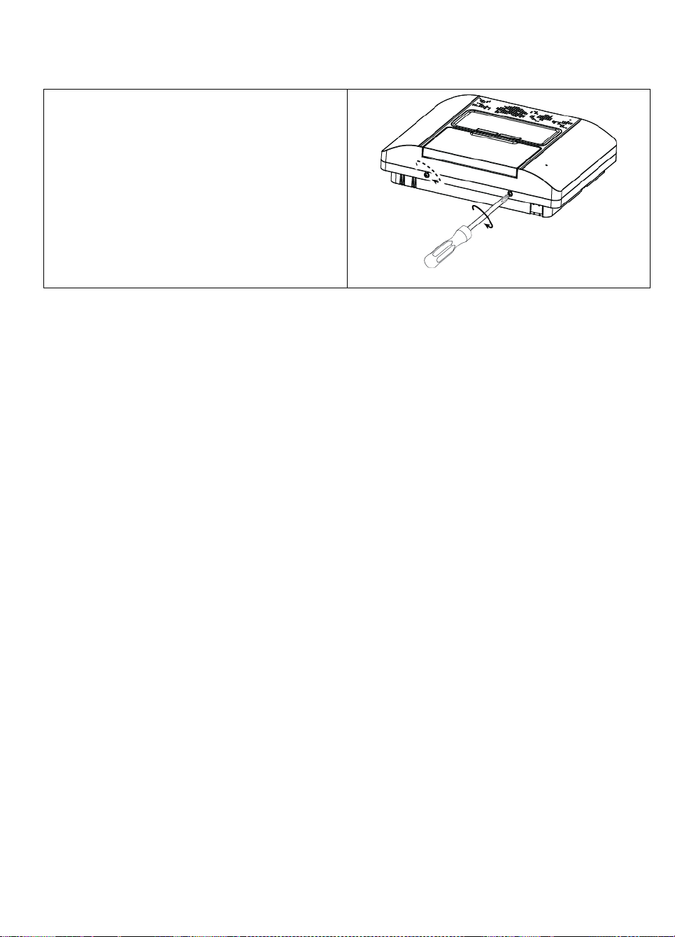
4.13 Closing the WP8030Control Panel
To Close the Control Panel:
1. Connect the flat cables, between front and back units,
in their respective connectors (up to 3, according to
options).
2. Close the panel and fasten the 2 screws.
3. Switch on the control panel; make sure that the
"Power" indicator on the control panel lights green.
Figure 4.13
- Final Closure
Control panel final closure is shown below.
3. WP8010 INSTALLATION
D-306233 CUSDOC PM-10/30 V18 DSC TRIPLE EN INST 27
3. WP8010 INSTALLATION
Button
Definition
Navigation / Setting Function
NEXT
Use to move / scroll forward to the next menu options.
BACK
Use to move / scroll backward to the previous menu options.
OK
Use to select a menu option or to confirm a setting or action.
HOME
Use to move one level up in the menu or to return to previous setting step.
AWAY
Use to jump back to the [<OK> TO EXIT] screen to quit programming.
OFF
Use to cancel, delete, clear or erase setting, data, etc.
0 – 9
Numerical keypad used to enter numerical data when needed.
1
2
5. PROGRAMMING
5.1 General Guidance
This chapter explains the Installer programming (configuration) options of your WP8010/WP8030 system and how to
customize its operation to your particular needs and end user requirements.
The control panel includes a partition feature. Partitioning allows you to have up to three independently controllable
areas with different user codes assigned to each partition. A partition can be armed or disarmed regardless of the
status of the other partitions within the system.
The Soak Test1 feature allows selected zones to be tested for a pre-defined period of time. When in Soak Test mode,
activating a zone does not cause an alarm and siren and strobe are not activated. The zone activation is recorded in
the event log and is not reported to the Monitoring Station. The zone remains in Soak Test until the pre-defined period
of time for the Soak Test has elapsed without any alarm activation. The zone then automatically removes itself from
Soak Test mode and returns to normal operating mode.
Software Upgrade2 allows you to upgrade the software of the control panel from the remote PowerManage server.
During software upgrade, the WP8010/WP8030 display will read "UPGRADING…" which is displayed throughout the
software upgrade procedure.
Note: Software Upgrade cannot be performed when the control panel is armed AWAY or there is an AC failure.
Tech Tip :
For your convenience, we recommend programming the WP8010/WP8030 on the work bench before actual installation.
Operating power may be obtained from the backup battery or from the AC power supply.
ATTENTION! FIRST SWITCH ON THE CONTROL PANEL and then INSERT BATTERIES INTO ACCESSORIES
DEVICES.
The devices "search" for the control panels to which they are enrolled for a period of only 24 hours from the time of
battery insertion.
Note: If you have switched on the control panel a long time after inserting batteries into the accessories devices: Open
and then close the cover to activate the tamper switch (where applicable), or remove the battery and then put back the
battery.
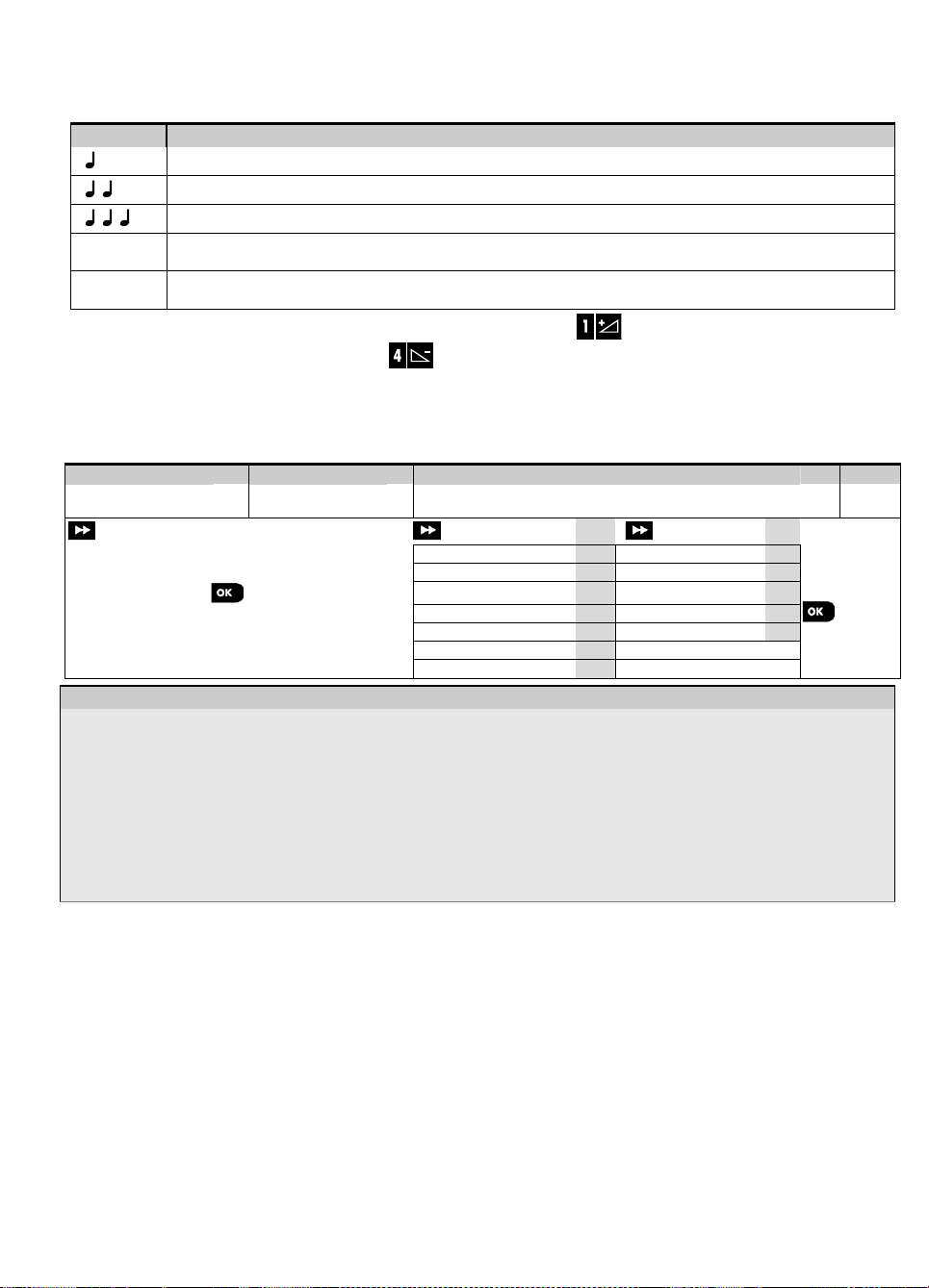
5.1.1 Navigation
The keypad's buttons are used for navigation and configuration when programming. The following table provides a
detailed description of the function or use of each button.
To review the options within the control panel menus and select an option, repeatedly press the Next
button to select the desired option (also designated as in this guide). To return to the previous options repeatedly
press the Home button and to exit the programming menu press the Away button.
To simplify the procedure further, you really need two basic buttons to program the entire panel: The Next
and the OK button. The button scrolls through the options, and the button selects the option
you want.
button until the desired option is displayed (also designated as in this guide), then press the OK
Soak Test is not applicable for UL installations.
Software Upgrade is not applicable for UL installations
28 D-306233 CUSDOC PM-10/30 V18 DSC TRIPLE EN INST
or Back
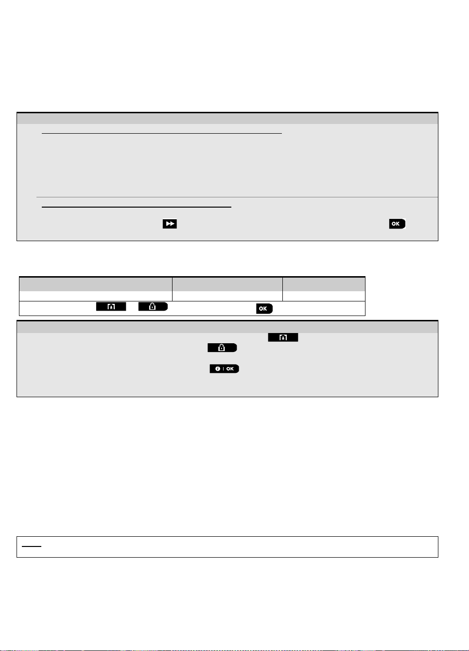
3. WP8010 INSTALLATION
Sound
Definition
Single beep, heard whenever a key is pressed
Double beep, indicates automatic return to the normal operating mode (by timeout).
Three beeps, indicates a trouble event
♫
Happy Tune (- - - –––), indicates successful completion of an operation.
♫
Sad Tune (–––––), indicates a wrong move or rejection
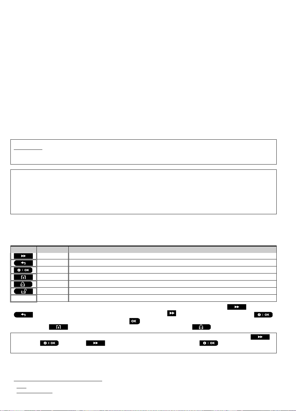
Step 1
Step 2
Step 3
Step 4
Select "INSTALLER
MODE" Option
[1]
Enter
Installer Code
[2]
Select "Installer Menu" Option
[3]
See See
READY 00:00
01:INSTALL CODES
5.3
08:USER SETTINGS
5.10
Go to
the
indicated
section
of the
selected
option
02:ZONES/DEVICES
5.4
09:FACTORY DEFLT
5.11
INSTALLER MODE
ENTER CODE:
03:CONTROL PANEL
5.5
10:SERIAL NUMBER
5.12
If the "Installer
Mode" is not shown,
refer to section 5.2.1
04:COMMUNICATION
5.6
12:PARTITIONING
5.13
05:OUTPUTS
5.7
13:OPERATION MOD
5.14
06:CUSTOM NAMES
5.8
<OK> TO EXIT
07:DIAGNOSTICS
5.9
- Entering the "Installer Mode" menu
[1]
You can access the "Installer Mode" only when the system is disarmed. The process described refers to the
case where "User permit" is not required. If "User permit" is required, select the "User Settings" option and
ask the Master User to enter his code and then scroll the "User Settings" menu and select the "Installer Mode"
option (last option in the menu). Continue to Step 2.
[2]
If you have not already changed your Installer code number, use the default settings: 8888 for installer & 9999 for
master installer.
If you enter an invalid installer code 5 times, the keypad will be automatically disabled for a pre-defined period of
time and the message WRONG PASSWORD will be displayed.
[3]
You have now entered the "Installer Menu". Scroll and select the menu you wish and continue to its
corresponding section in the guide (indicated on the right side of each option).
5.1.2 Feedback Sounds
The sounds you will hear while using and configuring the control panel are:
You can control the volume level of the sounded beeps by pressing the button on the keypad to increase the
volume of the beeps heard, or by pressing the button to decrease the volume of the beeps heard.
5.2 Entering the "Installer Mode" and Selecting a Menu Option
All installer menu options are accessed via the "Installer Mode" which is usually one of the main panel menu options.
To enter the "Installer Mode" and select an Installer Menu Option proceed as follows:
D-306233 CUSDOC PM-10/30 V18 DSC TRIPLE EN INST 29
3. WP8010 INSTALLATION
– Selecting an option from a menu
Example: To Select an Option from the "COMMUNICATION" menu:
[1]
Enter the Installer Menu and select the "04.COMMUNICATION" option (see section 5.2).
[2]
Select the sub-menu option you need, for example: "3: C.S. REPORTING".
[3]
Select the parameter you wish to configure for example: "11:RCVR 1 ACCOUNT"
[4]
To continue, go to the section of the selected sub-menu option, for example section 5.6.4 for the
"3:C.S.REPORTING" menu, and look for the sub-menu you wish to configure (e.g. "11:RCVR 1 ACCOUNT"). After
configuring the selected parameter the display returns to step 3.
To Change the Configuration of the Selected Option:
When entering the selected option, the display shows the default (or the previously selected) setting marked with .
To change the configuration, scroll the "Options" menu and select the setting you wish and press to
confirm. When done, the display reverts to Step 3.
Step 1
Step 2
Step 3
[1] [2] [3]
Any screen
or
<OK> TO EXIT
READY 12:00
– Exiting the Installer Mode
[1]
To exit "INSTALLER MODE", move up the menu by pressing the button repeatedly until the display
reads "<OK> TO EXIT" or preferably; press the button once which brings you immediately to the exit
screen "<OK> TO EXIT".
[2]
When the display reads "<OK> TO EXIT", press .
[3]
The system exits the “INSTALLER MODE" menu and returns to the normal disarm state while showing the
READY display.
5.2.1 Entering the "Installer Mode" if "User Permit" is enabled
In certain countries the regulations may require user permission to make changes in the configuration of the panel. To
comply with these regulations, the "Installer Mode" option can be accesses only via the "User Settings" menu. The
Master user must first enter the "User Settings" menu then scroll until the "Installer Mode" option is shown and then
the installer can continue as shown in the above table (see also [1] in Step 1 above).
To configure the panel to comply with user permission requirements - see option #91 "User Permit" in section 5.5.8.
5.2.2 Selecting options
5.2.3 Exiting the Installer Mode
To exit the Installer Mode, proceed as follows:
5.3 Setting Installer Codes
The WP8010/WP8030 system provides two installer permission levels with separate installer codes, as follows:
Master Installer: The "Master Installer" is authorized to access all Installer Menu and sub-menu options. The
default code is: 9999 (*).
Installer: The "Installer" is authorized to access most but not all Installer Menu and sub-menu options. The default
code is 8888 (*).
Guard Code: Enables an authorized guard to only Arm Away / Disarm the control panel. The default code is 0000 (*).
The following actions can be performed only by using the Master Installer code:
Changing the Master Installer code.
Defining specific communication parameters – see "3:C.S REPORTING" in sections 5.6.1 and 5.6.4.
Resetting the WP8010/WP8030 parameters to the default parameters – see "09:FACTORY DEFLT" in section
5.11.
Note: Not every system includes a Master Installer code feature. In such systems, the Installer can access all Installer
Menu and sub-menu options the same as a Master Installer.
(*) You are expected to use the default codes only once for gaining initial access, and replace it with a secret
code known only to yourself.
30 D-306233 CUSDOC PM-10/30 V18 DSC TRIPLE EN INST
 Loading...