

DSC Touch-SCW9067 Installation Manual
INSTALLATION MANUAL
DSC Touch 1.4.3 Software
The DSC Touch is a 7” touchscreen built with an
Android operating system, providing full security and
smarthome functionality in an easy to use interface.
INTRODUCTION
INCLUDED IN BOX
ABOUT THIS GUIDE
DSC Confidential and Proprietary Page of 2 114
© Last updated 4/29/15 All rights reserved
?
QUESTIONS?
Contact us us at
800-387-3630 or
tech@dsc.com
SUPPORT
This document outlines the basic hardware specifications and software directions to
install and customize the DSC Touch. Note that the information presented is not
comprehensive, but is specifically dedicated to those menus, features, and systems
accessible solely to those with the proper installation code. Features accessible to
users and installers alike are outlined in the DSC Touch User Guide. The information
contained is confidential and proprietary, and is solely owned by DSC. Any
reproduction, modification or distribution without permission is strictly prohibited.
This manual covers the following
models of DSC Touch Alarm
System:
- SCW9067C (CDMA model)
- SCW9067H (HSPA model)
Reference to DSC Touch
throughout this manual applies to
all these models unless stated
differently.
Power
Supply
DSC
Touch

TABLE OF CONTENTS
CONTENTS
HARDWARE
5- Exterior Front
6- Exterior Back
7- Interior
8- Wiring Diagram
9- Installing the Back Plate
10- Powering the Panel
11- Mounting the Hardware
SOFTWARE
13- Home Screen Overview
14- Header or “Status” Bar
15- Footer
16- Settings
17- Settings Menu
INSTALLATION
19- Installation
20- Security Account
23- Security Sensors
24- AutoLearn Sensor
25- Add Sensor
26- Sensor Types
27- Sensor Name
29- Chime Type
30- Sensor Groups
44- Voice Prompt
45- Home Control Devices
47- Add Device
48- Clear Device
49- Delete Device
50- Remove All Devices
51- Rediscover Network
52- Neighbor Info
53- Counters
54- Timer
55- Sound
57- System Logs
58- Upgrade Software
59- Siren and Alarms
60- Security and Arming
62- Camera Settings
63- Device List
64- IQ2 Devices
65- Dual Path
SYSTEM TESTS
67- System Tests
68- Wi-Fi Test
69- Sensor Test
70- Cellular Test
71- Image Sensor Config
72- Home Control Test
73- Panel Test
74- IQ2 Devices Test
CUSTOMIZATION
76- System Settings
77- How to Connect Wi-Fi
78- Weather
79- Photo Frame
81- Load Images from SD
Card
82- Photo Frame Settings
Custom Names
83- Dealer Contact
84-Custom Names
85-Edit Chimes
86- User Management
87- Load Help Videos
TROUBLESHOOTING
89-About
92-Upgrade Software Using
Wi-Fi
93- Automatic Software
Updates
94- Software Update Via SD
Card
95- Power Down
96- Panel Reboot
97- Hard Reboot
98- Panel Test
Troubleshooting
101- System Monitor
102- Cannot Load Help
Videos
LEGAL
103- Important Information
SPECIFICATIONS
112- Hardware Specifications

HARDWARE
HARDWARE
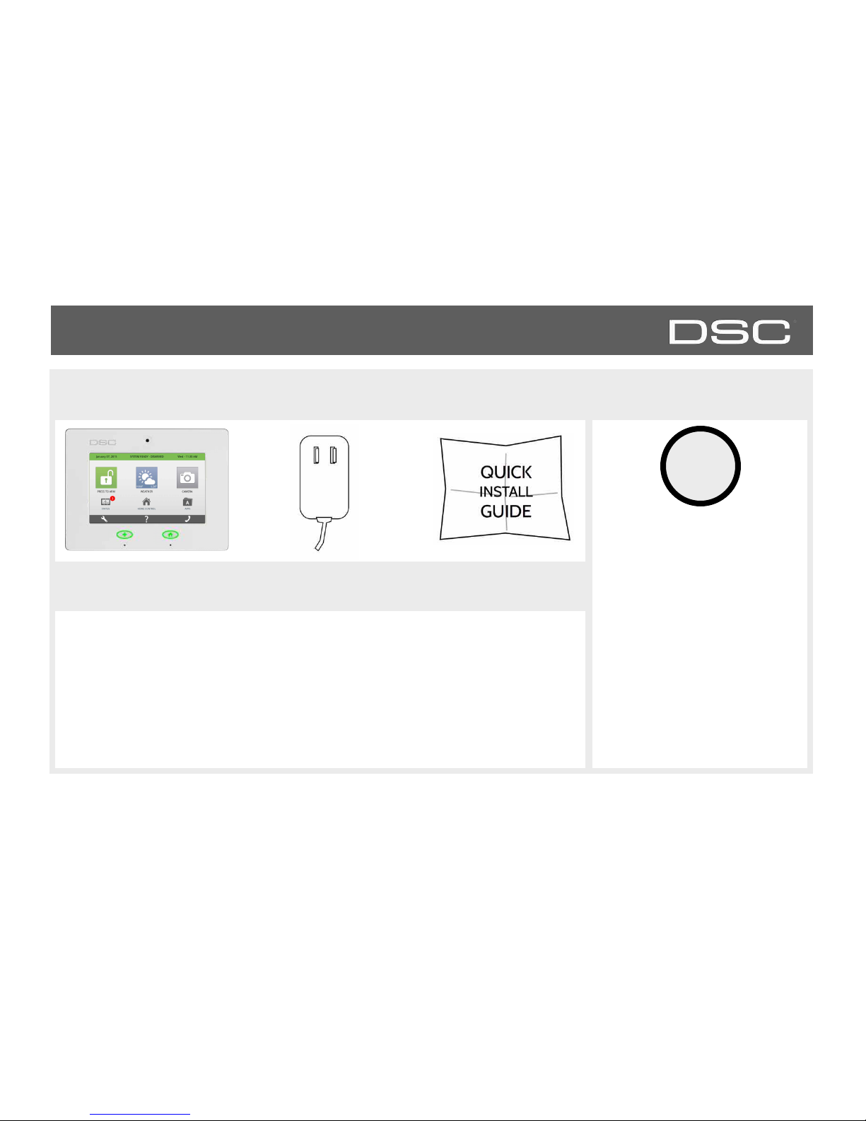
EXTERIOR FRONT
Panel Camera
Emergency Button
Home Button
Microphone
7” LCD Resistive
Touch Screen
DSC Confidential and Proprietary Page of 5 114
© Last updated 4/29/15 All rights reserved
HARDWARE
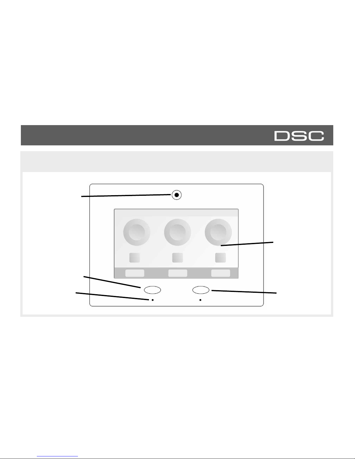
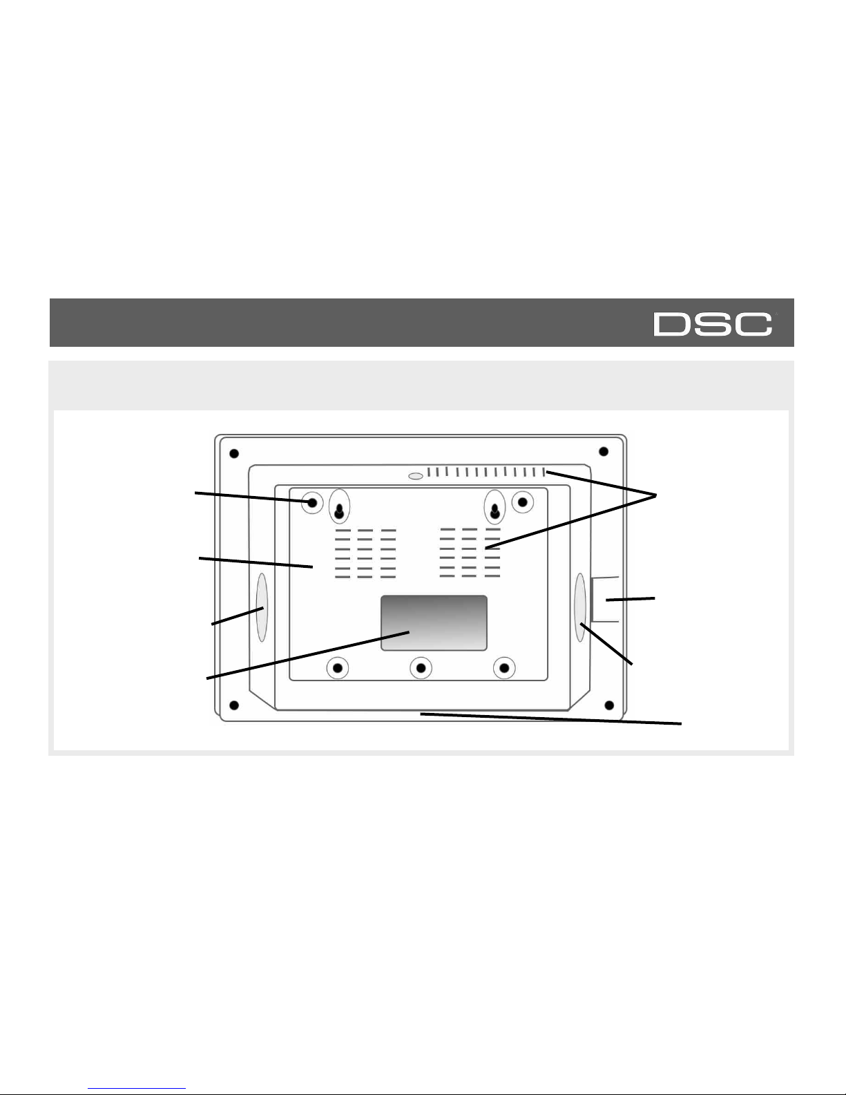
EXTERIOR BACK
Mounting plate
Mounting holes
SD Card Slot
Cooling Vents
Two-Way Voice
Speaker
Panel Sounds Speaker
Rear access opening
Siren
DSC Confidential and Proprietary Page of 6 114
© Last updated 4/29/15 All rights reserved
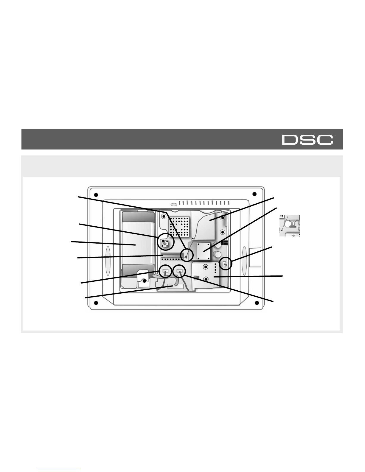
HARDWARE
INTERIOR
Battery*
Image Sensor Radio
Z-Wave Radio
Battery Connector*
Cellular Module
Terminal Block
Tamper Switch
Microphone Connector
Two-Way Voice Speaker
Connector
Panel Speaker Connector
Cellular Antenna
The battery should NEVER be disconnected without following proper power-down procedures (page 92)
Failure to comply may result in data corruption, panel failure, and a void of the manufacturer's warranty
*CAUTION
Note:
HSPA Models will
contain a SIM card
DSC Confidential and Proprietary Page of 7 114
© Last updated 4/29/15 All rights reserved
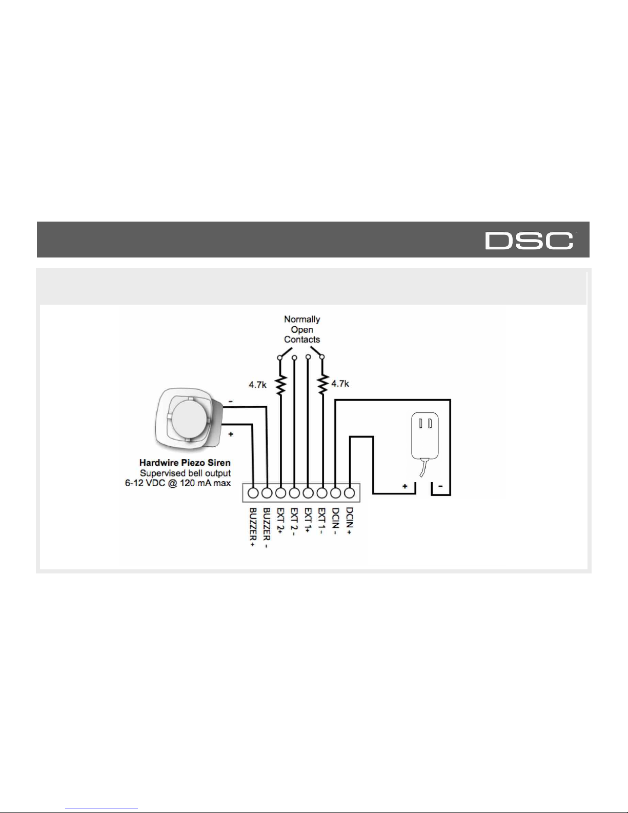
HARDWARE
WIRING DIAGRAM
DSC Confidential and Proprietary Page of 8 114
© Last updated 4/29/15 All rights reserved
Note:
Only DCIN-, DCIN+ terminals evaluated by
UL/cUL. Other terminal connections have
not been evaluated by UL/cUL.
Note: Do not connect the plug
in adapter to a switched outlet.
Note:
Use only Class 2 power limited power supply
Input rating: 100-240VAC, 50/60Hz, 1A
Output rating: 12.5VDC/1.2A
Model MU15-R125120-A1 (P/N MU15-R1125-A00S) for USA
Model MU15-R125120-A1 (P/N MU15-R1125-A01S) for Canada
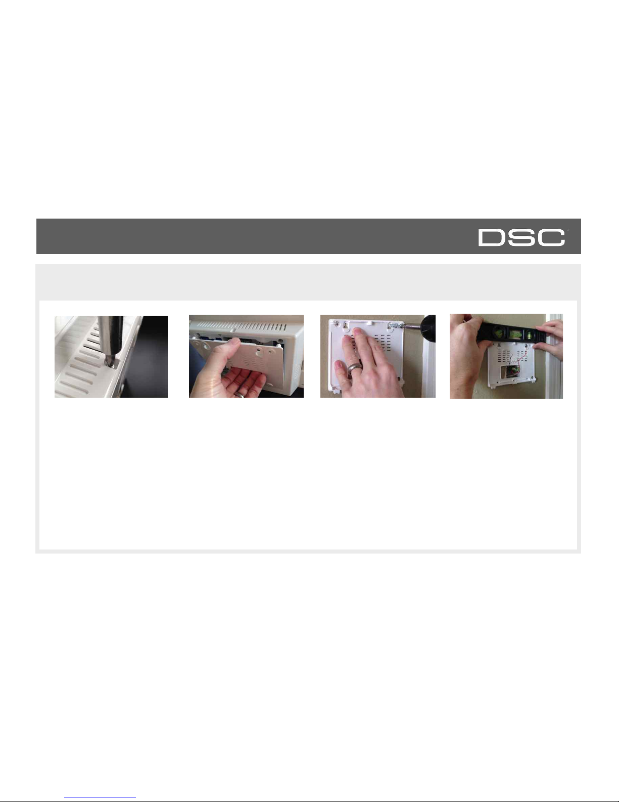
HARDWARE
INSTALLING THE BACK PLATE
Remove the retainer screw
and place in a safe location
Remove the back plate
from the panel by pulling
downward from the top
Secure one corner of the
plate in the desired
location, be sure to
position rear access
opening over the location
of your wire
Ensure the plate is level
and secure to wall with
appropriate mounting
hardware (not provided)
DSC Confidential and Proprietary Page of 9 114
© Last updated 4/29/15 All rights reserved
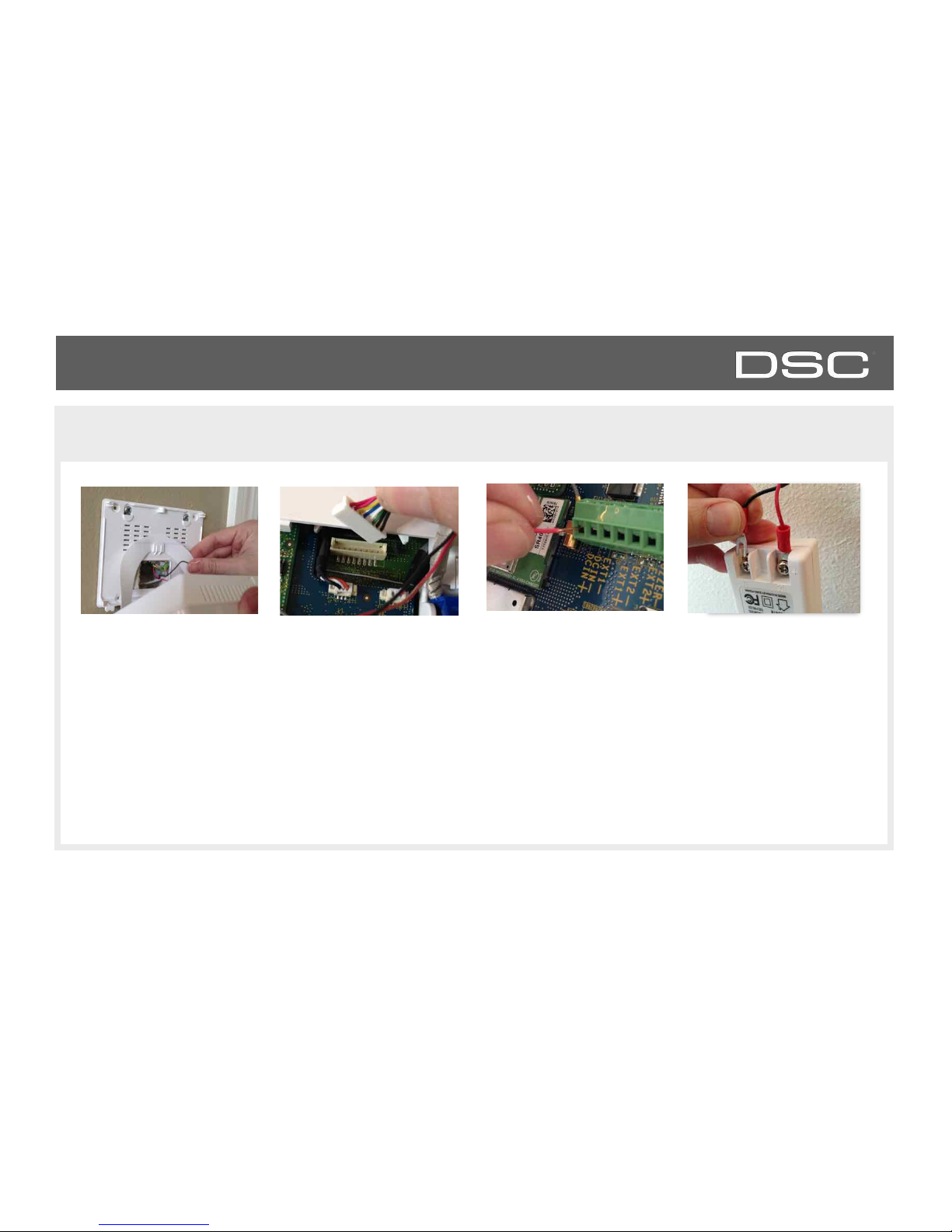
HARDWARE
POWERING THE PANEL
Hang the panel’s
suspension strap on the
hook mounted to the back
plate.
Connect power supply
wire to terminal block.
Red- DCIN +
Black- DCIN-
Plug in battery connector
CAUTION: Once connected, DO NOT unplug
the battery without following proper power
down procedures (page 92). Disconnecting the
battery may result in data corruption or panel
failure and a void of the manufacturer warranty.
Connect the wire to Power
Supply terminals.
Red- Positive
Black- Negative
IMPORTANT: Reversing
polarity on these wires may
cause damage to the panel.
DSC Confidential and Proprietary Page of 10 114
© Last updated 4/29/15 All rights reserved
IMPORTANT: To ensure proper
power at the panel, 18AWG wire, no
longer than 25 feet, should be used
between the Panel and the Power
Supply.
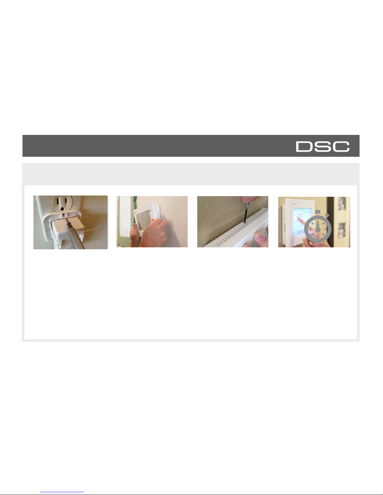
HARDWARE
MOUNTING THE HARDWARE
Slide bottom of panel up
to the back plate and tilt
upward until it snaps in
place.
Replace retainer screw and
tighten
Fasten power supply
mounting tab to receptacle.
Note: The power supply
model with mounting tab
shall be used only for
installations in USA. For
installations in Canada use
only the power supply
model without the
mounting tab.
Wait up to 3 minutes for
the DSC Touch to fully
boot up.
DSC Confidential and Proprietary Page of 11 114
© Last updated 4/29/15 All rights reserved
SOFTWARE
SOFTWARE
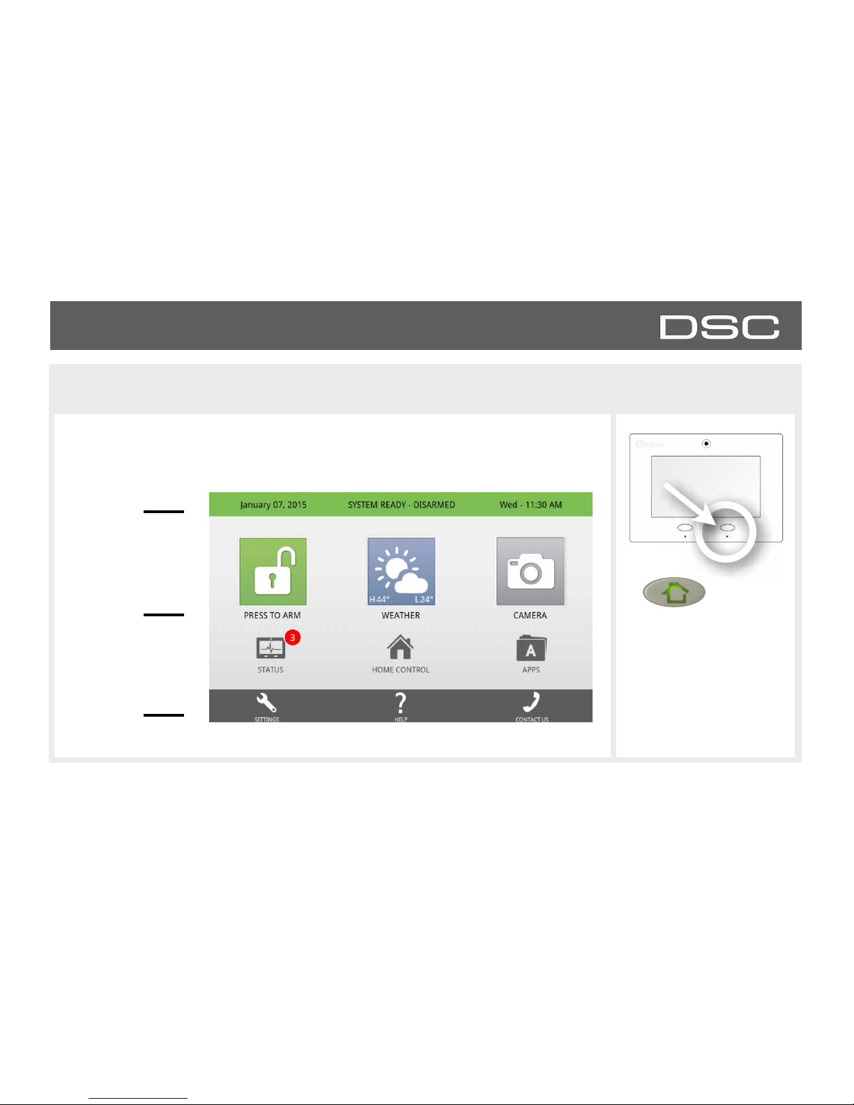
HOME SCREEN OVERVIEW
Header or
“Status” Bar
Primary
User
Interface
Footer or
“Help” Bar
FIND IT
The home screen is divided into three sections. The header shows the date, time and is
color coded to show current status. The primary user interface contains the panel apps,
and the footer holds settings, help, and the dealer contact portal.
Home
DSC Confidential and Proprietary Page of 13 114
© Last updated 4/29/15 All rights reserved
SOFTWARE
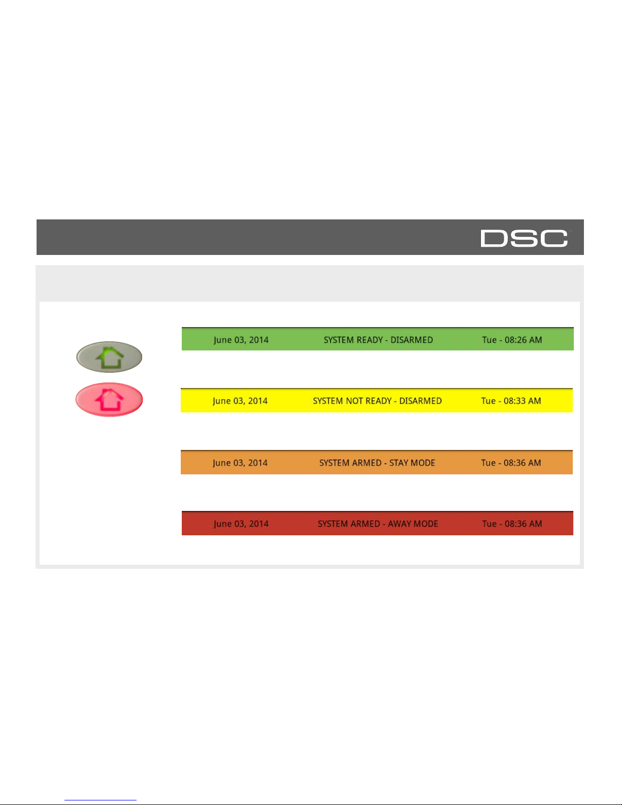
HEADER OR “STATUS” BAR
The green header is labeled “System Ready – Disarmed” which indicates that all of the
sensors are closed and the system is ready to be armed.
The yellow header is labeled “System Not Ready – Disarmed” which indicates that one or
more of the sensors are tampered or open. Touch the bar to see a list of these sensors.
The red header is labeled “System Armed-Away Mode” which indicates that ALL nonbypassed sensors are armed.
The header or “Status” bar shows the date, time and is color coded to show the current system status.
The panel’s “Panic” and
“Home” buttons also
illuminate to show panel
status. These LED lights will
NOT illuminate if the panel
is running on battery only
Green LED when disarmed
Red LED when armed
DSC Confidential and Proprietary Page of 14 114
© Last updated 4/29/15 All rights reserved
The orange header is labeled “System Armed-Stay Mode” which indicates that nonbypassed doors and windows are armed.
SOFTWARE
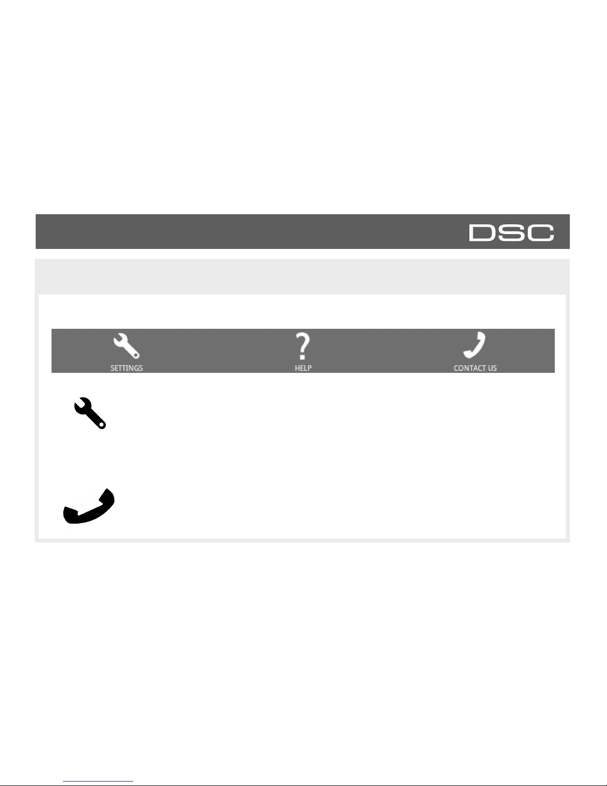
FOOTER
The footer bar contains Settings, Help and Contact Us (dealer contact portal).
Settings
Access panel installation and customization options. This area requires a valid Dealer, Installer or
Master code and provides varied access by user permission level.
Help
Access video tutorials, FAQs, and URLs for other documentation.
Contact Us
Access dealer/security provider contact information including phone numbers, website and e-mail
address for support and service. (content pushed automatically from dealer’s Alarm.com account)
?
DSC Confidential and Proprietary Page of 15 114
© Last updated 4/29/15 All rights reserved
SOFTWARE
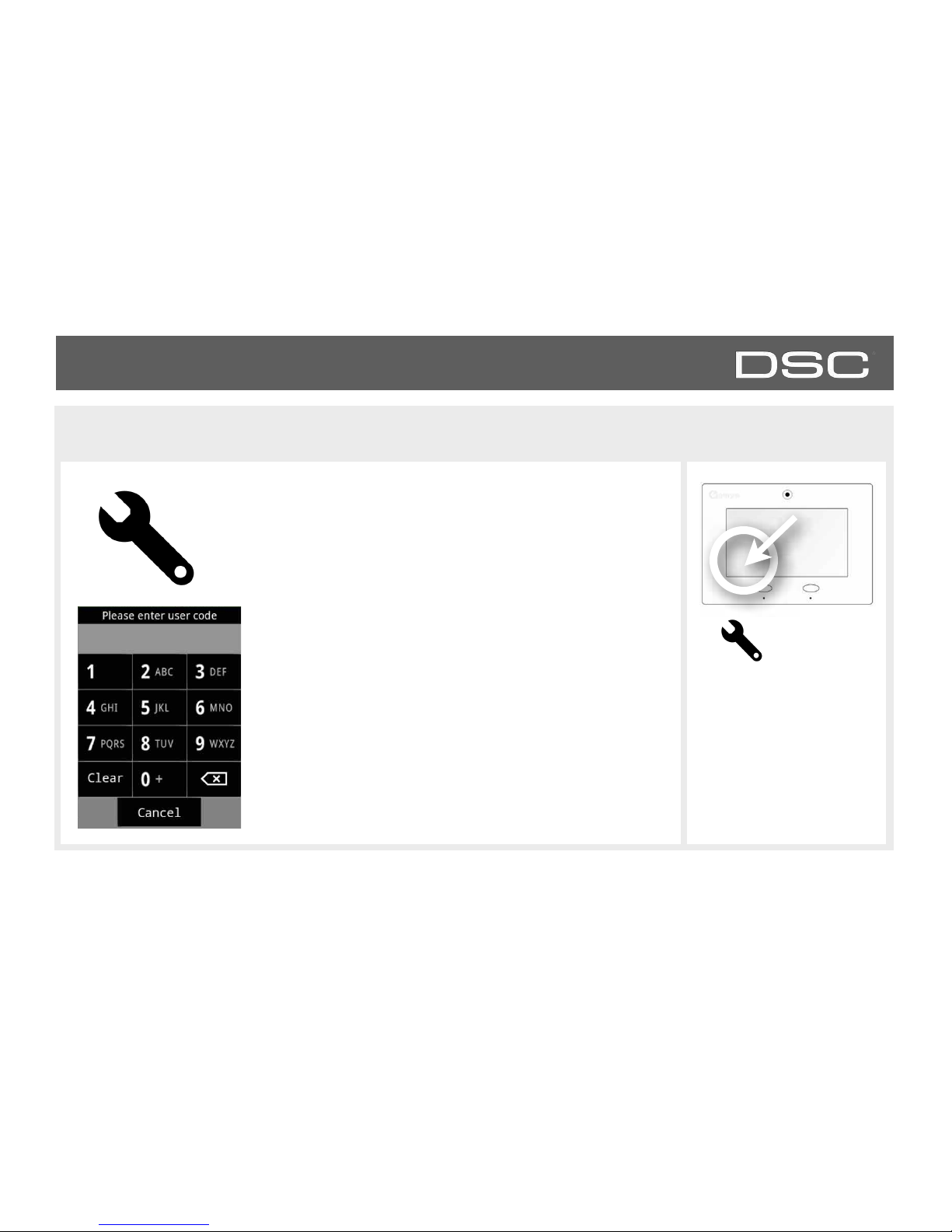
SETTINGS
To access Settings you must enter a code, however only the
Dealer and Installer code has access to installation options. The
Master Code does NOT have access to the installation menu.
FIND IT
Settings
DSC Confidential and Proprietary Page of 16 114
© Last updated 4/29/15 All rights reserved
Default Installer Code
5555
Default Master Code
1234
Access to all
functions to install
and customize the
panel and
peripherals
Access to limited
functions,
including editing
sensor names,
camera app, user
management,
and connecting
to Wi-Fi
Default Dealer Code
5555
Access to all
functions to install
and customize the
panel and
peripherals as well
as Master Reset
and Dealer
Contact.
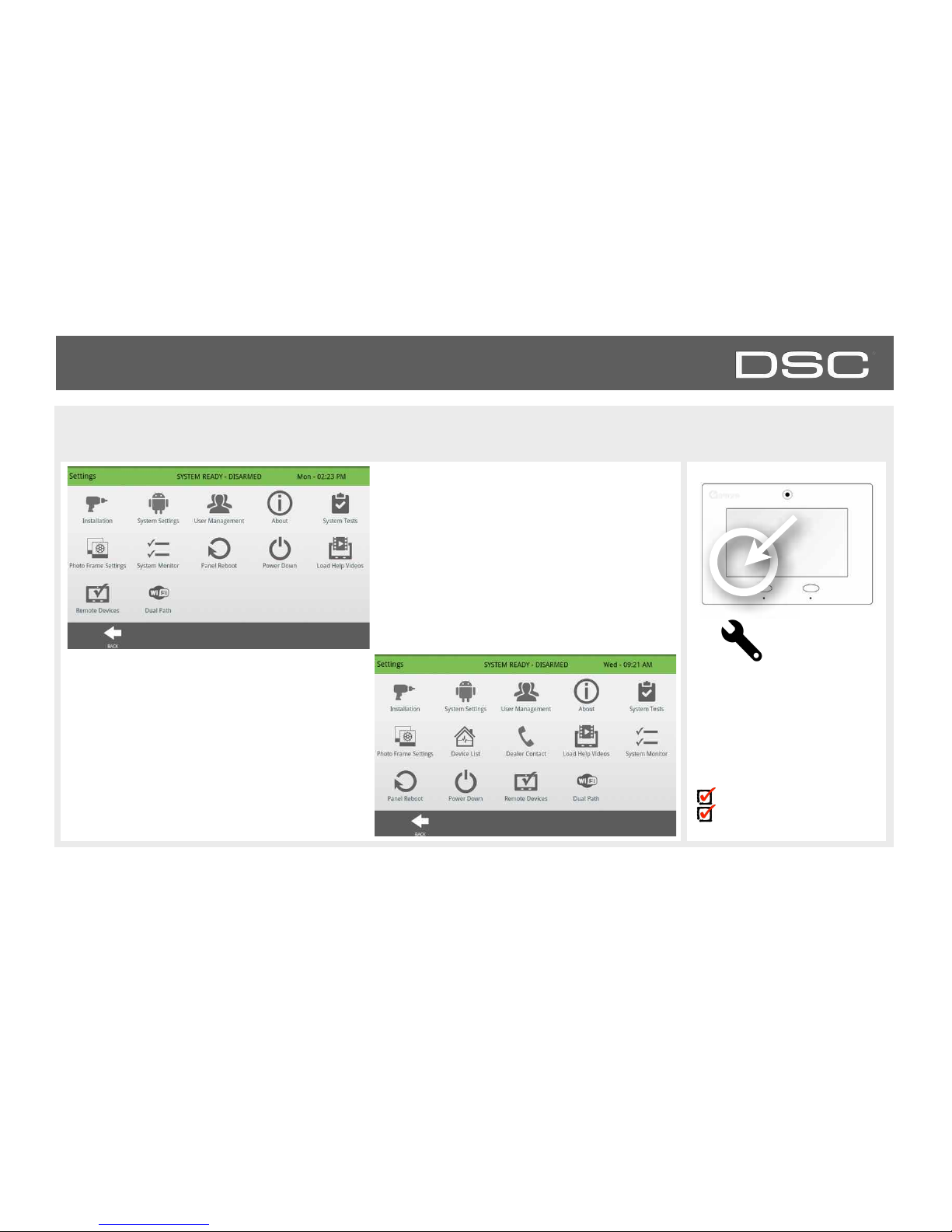
SOFTWARE
SETTINGS MENU
FIND IT
Settings
Installer Code Access
Master Code Access
DSC Confidential and Proprietary Page of 17 114
© Last updated 4/29/15 All rights reserved
Settings Menu accessed through the
Installer Code:
5555
Settings Menu accessed through the
Dealer Code:
5555

INSTALLATION
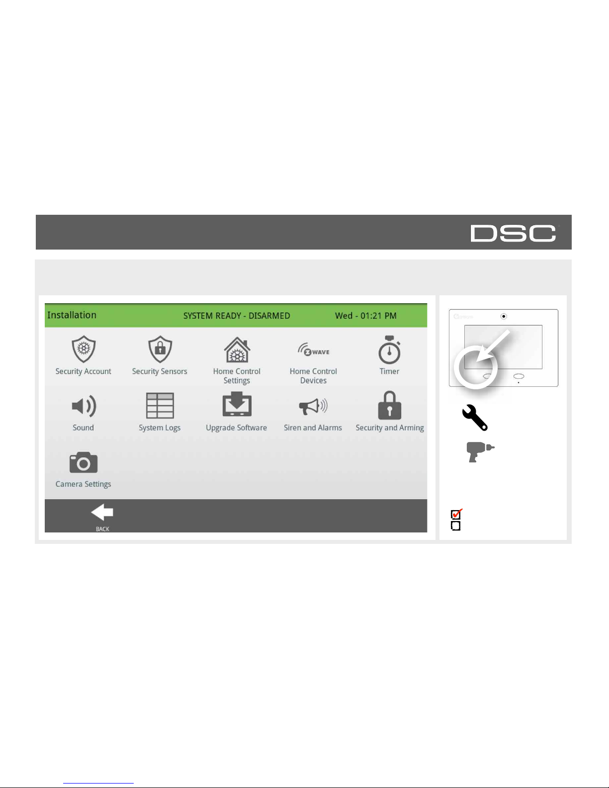
INSTALLATION
INSTALLATION
FIND IT
Settings
Installation
Installer Code Access
Master Code Access
DSC Confidential and Proprietary Page of 19 114
© Last updated 4/29/15 All rights reserved

INSTALLATION
SECURITY ACCOUNT
FIND IT
Settings
Installation
Security
Account
Setting
Default
Description
Account Number
blank
Security provider account number (up to 10 characters)
Power Management
Enabled
An energy-saving function when running on battery power only
Power Management Sleep
Timeout
1
Panel initiates power management mode a specified number of
minutes after last touch
Power Restoration
Disabled
Turn on or off sensor hold for 60 seconds during power!
restoration.
Loss of Supervisory Signals
for Emergency Sensors
4
Select the length in hours (4) before reporting a loss of!
supervision on life safety devices.
Loss of Supervisory Signals
for Non Emergency Sensors
24
Select the length in hours (24) before reporting a loss of!
supervision on security devices
Loss of AC Power Timeout
3
Select the length in minutes (1-10) before reporting an AC power
loss.
Loss of Cell Signal Timeout
30
Select the length in minutes (10-120) before reporting a loss in
cellular signal.
Installer Code Access
Master Code Access
DSC Confidential and Proprietary Page of 20 114
© Last updated 4/29/15 All rights reserved
Note: For UL/cUL, the wireless supervision window for Emergency sensors (Smoke detectors, CO detectors) shall be set to 4h.
INSTALLATION
SECURITY ACCOUNT
FIND IT
Installer Code Access
Master Code Access
Setting
Default
Description
Entry/Exit delays limits
Disabled
When enabled, the range for entry and exit delays is as follows:!
-Entry delay: 30-240 seconds,Exit Delay: 45-254 seconds!
When disabled, the range for entry and exit delays are as follows:!
-Entry delay: 5 to 240 seconds, Exit delay: 5 to 254 seconds!
Note: for UL/cUL set entry delay to 45 sec. and for UL set exit delay to max 120 sec. and
for cUL set exit delay to 60 sec.
Weather Temperature
F
Select the temperature format. (Fahrenheit or Celsius)
Languages
English
Select a panel language. All settings and menus will change except
videos. (English, French and Spanish)
Favourite Languages
English/
Spanish
Select your favourite languages. This setting determines what 2
languages the bi-lingual toggle uses in the Apps section. Favourite 1
is the primary language on the panel, favourite 2 is the secondary
language. (English, French and Spanish)
IQ2 Panel
Enabled
Enable or Disable the ability to pair an IQ2 secondary panel.
Jam Detection*
Disabled
When enabled the system can detect when an unusual amount of
RF signals are being transmitted leading to a potential panel
malfunction. This will report to the central station and handled
accordingly.
Jam Detection Local Alarm*
Disabled
When enabled the system will sound a local alarm. “Jam Detection”
must be active for this to function properly.
Settings
Installation
Security
Account
* Additional options available
only through the Dealer Code.
Setting
Default
Description
RF Jam Sensitivity Level*
High
Choose between HIGH and LOW sensitivity levels.
Open/Close Reports
Allowed For Auto Learn
Disabled
Rather than sending a tamper to auto learn a sensor, enabling this
will allow an open/close of the sensor to trigger auto learn
INSTALLATION
SECURITY ACCOUNT
DSC Confidential and Proprietary Page of 22 114
© Last updated 4/29/15 All rights reserved
FIND IT
Installer Code Access
Master Code Access
Settings
Installation
Security
Account
* Additional options available
only through the Dealer Code.
INSTALLATION
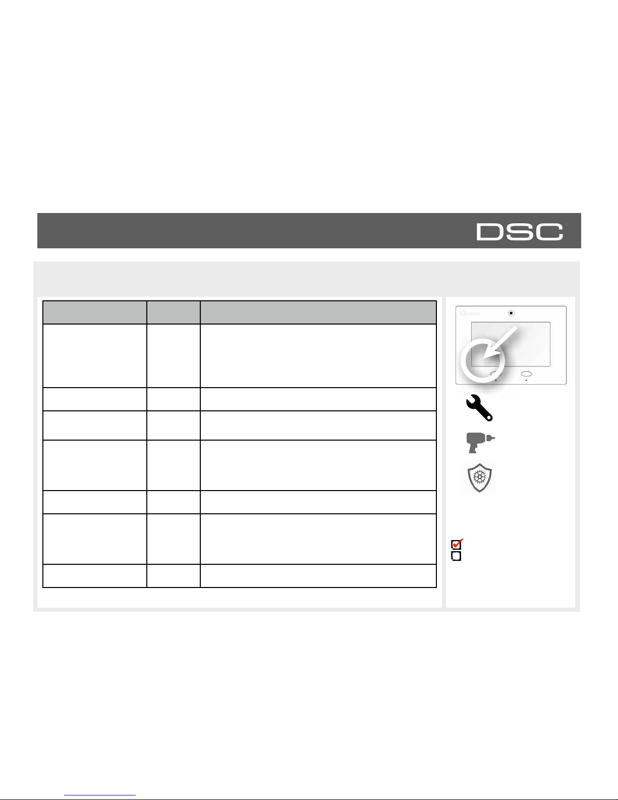
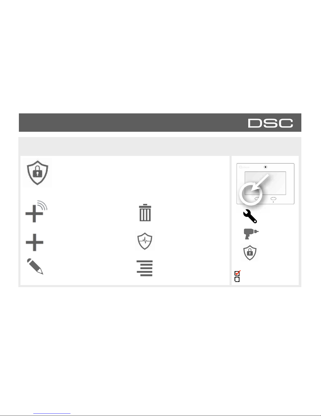
SECURITY SENSORS
FIND IT
Settings
Installation
Security
Sensors
Auto Learn Sensor
Pair sensors quickly by tripping or
tampering and then editing the
information
Add Sensor
Pair sensors manually by typing in
a DL code or Serial number.
Edit Sensor
Make changes to existing sensors
Delete Sensor
Remove sensor
Sensor Status
Monitor sensor status in
realtime.
Sensor Group
Quick reference to all sensor
groups and their actions
Security Sensors
Add, edit or remove up to 64 security or life safety devices. 5 of which being
allocated for image sensors. Note: image sensors functionality has not been investigated by
UL/cUL. This is a supplementary feature that does not interfere with mandatory life safety and
security protection operation of the alarm system control unit.
Installer Code Access
Master Code Access
DSC Confidential and Proprietary Page of 23 114
© Last updated 4/29/15 All rights reserved

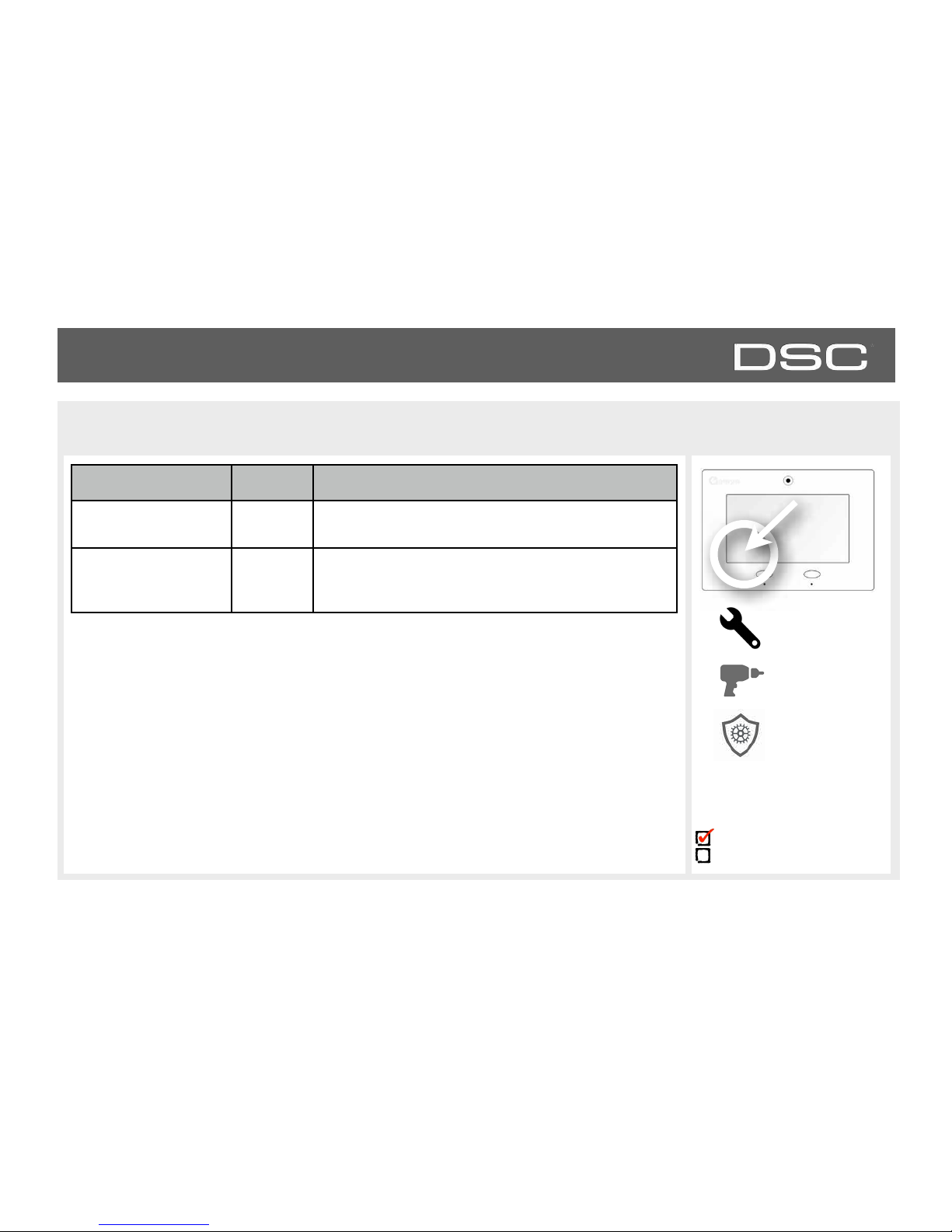
INSTALLATION
AUTO LEARN SENSOR
1. Select “Auto Learn Sensor”
2. Open and close or tamper a sensor to enroll. Image
sensors have a 2 min enrolling window.
3. Panel will chime and display the sensor’s DL code, select
OK to confirm.
4. Use drop down menus and “smart” filters to program
Sensor Group, Chime etc..
5. Select “Add New” to complete and move to the next sensor.
FIND IT
Settings
Installation
Security Sensors
Auto Learn
Sensor
Installer Code Access
Master Code Access
DSC Confidential and Proprietary Page of 24 114
© Last updated 4/29/15 All rights reserved
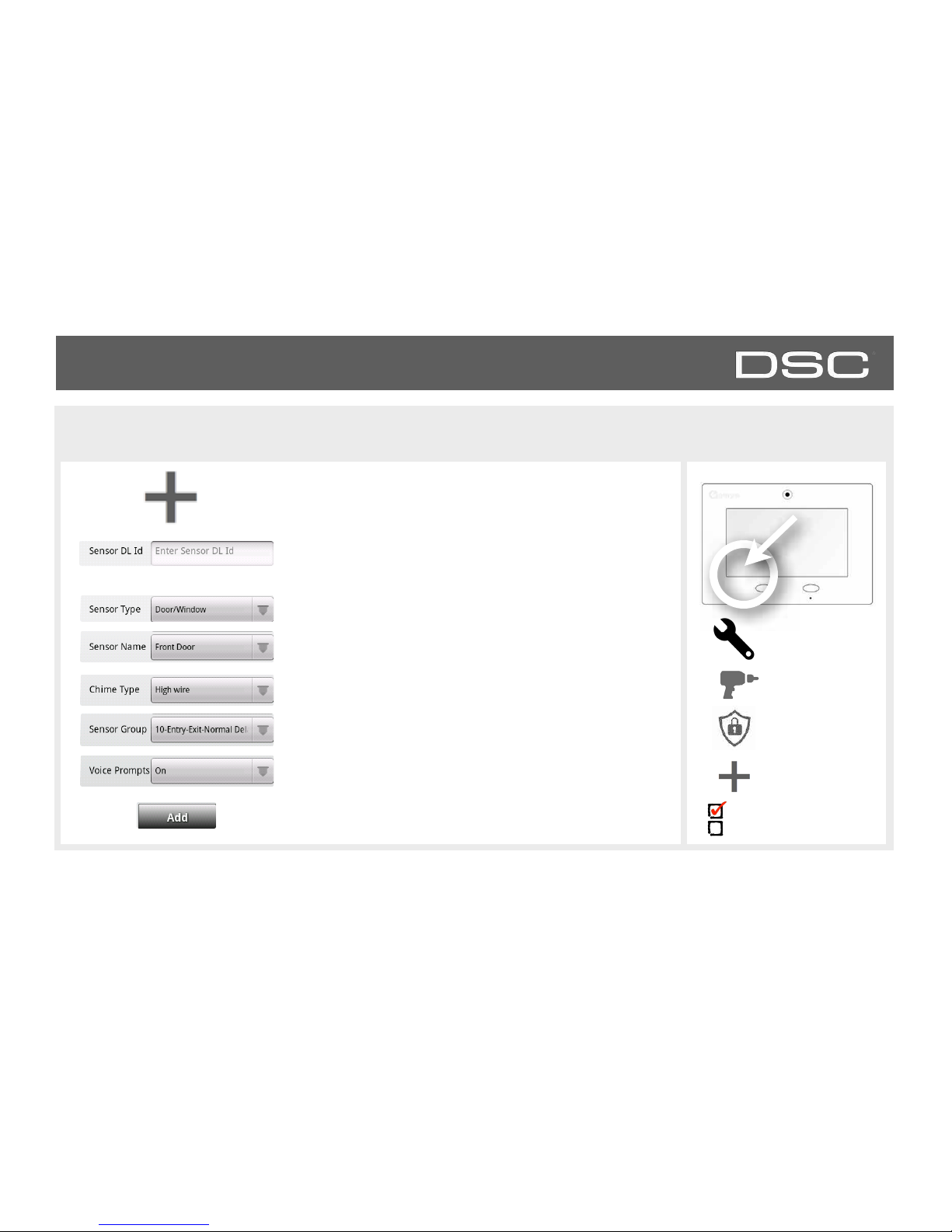
INSTALLATION
ADD SENSOR
1. Select “Add Sensor” (NOTE: These same fields can be
edited later from the “Edit Sensor” app)
2. Tap the field marked “Sensor DL ID” to open the
keyboard. Enter the six digit DL code on the back of the
device and touch “Done”
3. Choose sensor type from list
8. Click “Add New” to save the information and
complete the process.
FIND IT
Settings
4. Choose sensor name from the list or create a “Custom
Name” using the built in keyboard with Text to Speech.
5. Choose chime type from list
6. Indicate sensor group from list
7. Indicate whether you want voice prompts on or off
Installation
Security Sensors
Add Sensor
Installer Code Access
Master Code Access
DSC Confidential and Proprietary Page of 25 114
© Last updated 4/29/15 All rights reserved
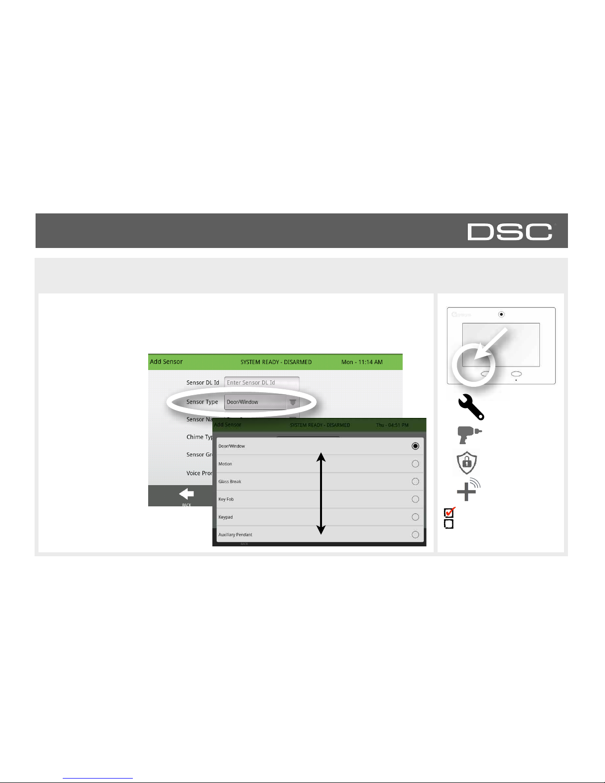
When adding or editing security devices you can choose from the following sensor types:
INSTALLATION
SENSOR TYPES
FIND IT
Settings
Installation
Security Sensors
AutoLearn
Sensor
Installer Code Access
Master Code Access
DSC Confidential and Proprietary Page of 26 114
© Last updated 4/29/15 All rights reserved
Door/Window
Motion
Glass Break
Key Fob
Keypad
Auxiliary Pendant
Smoke Detector
CO Detector
Hardwire Translator
Wireless Translator
Heat
Water
Shock Sensor
Freeze
Tilt
Image Sensor
Door Bell
Smoke-M
Door/Window-M
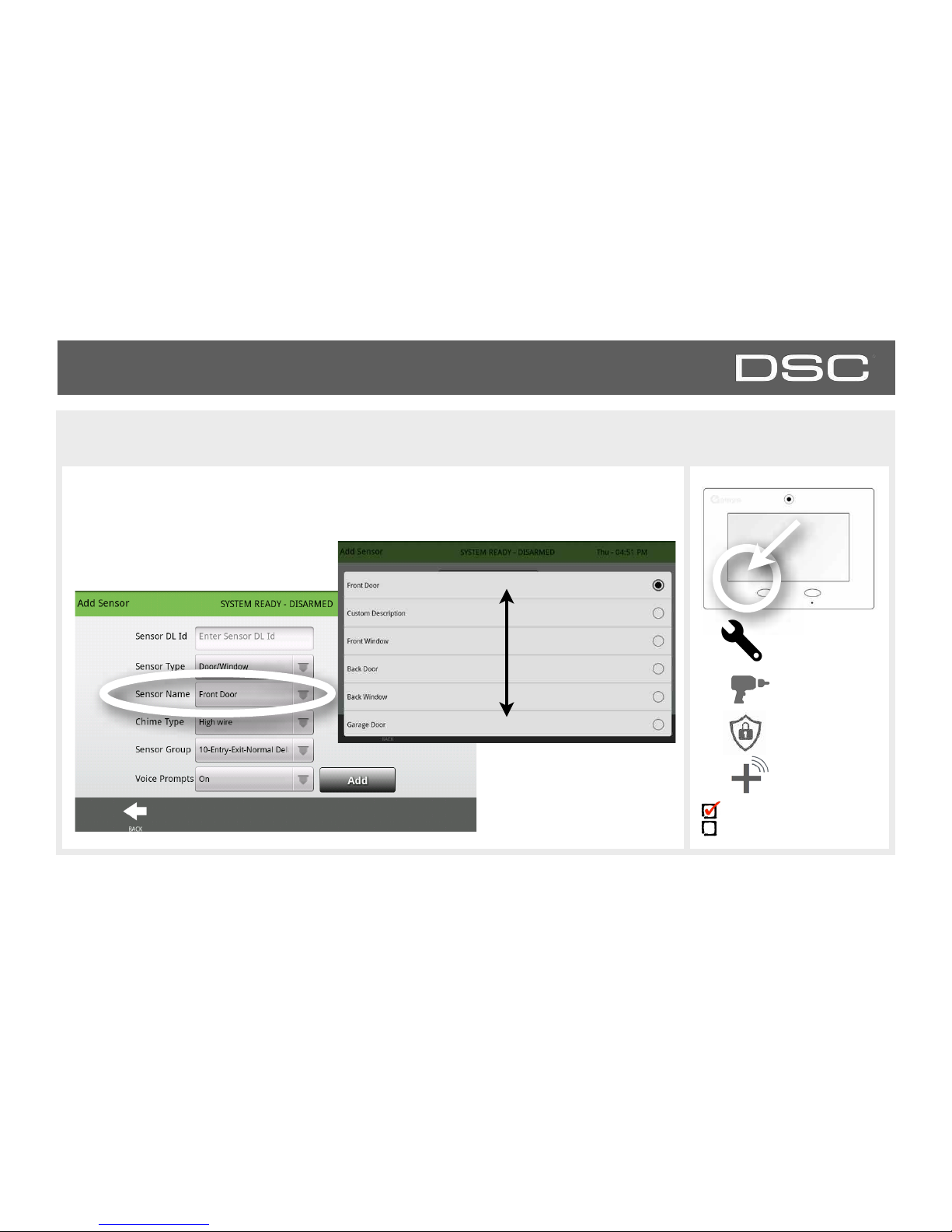
INSTALLATION
SENSOR NAME
When you select the sensor name field you can choose from a variety of preset sensor
names by scrolling up and down or create a custom description.
FIND IT
Settings
Installation
Security Sensors
AutoLearn
Sensor
Installer Code Access
Master Code Access
DSC Confidential and Proprietary Page of 27 114
© Last updated 4/29/15 All rights reserved
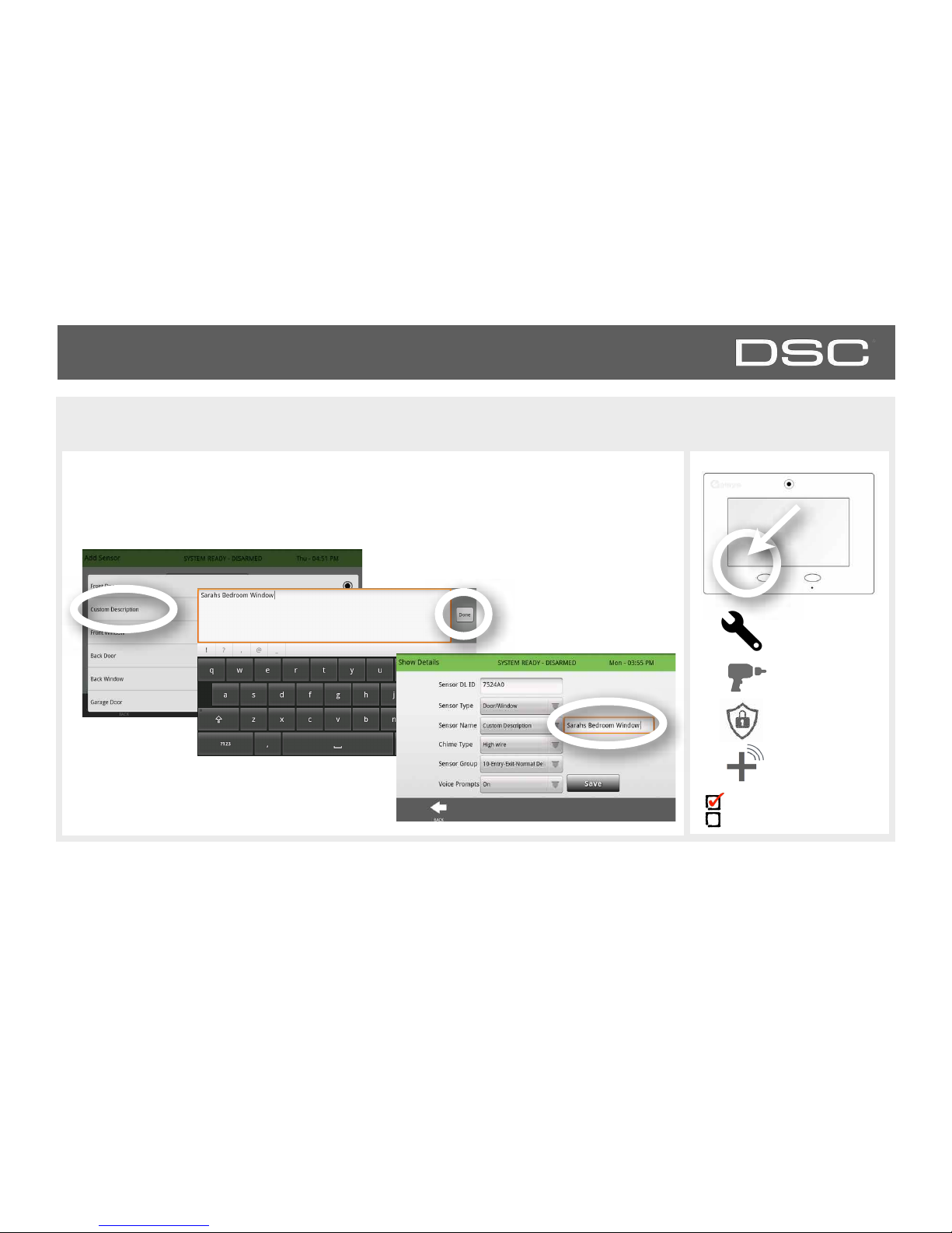
INSTALLATION
SENSOR NAME: CUSTOM DESCRIPTION
When you select “Custom Description” as your sensor name the keyboard will appear.
Type in the desired name (up to 24 characters, alphanumeric only, no special characters)
and click “Done.” The name will appear in the field next to “Sensor Name.”
FIND IT
Settings
Installation
Security Sensors
AutoLearn
Sensor
Type sensor name,
touch “Done”
Name appears
in the box
Installer Code Access
Master Code Access
Use the keyboard to type
DSC Confidential and Proprietary Page of 28 114
© Last updated 4/29/15 All rights reserved
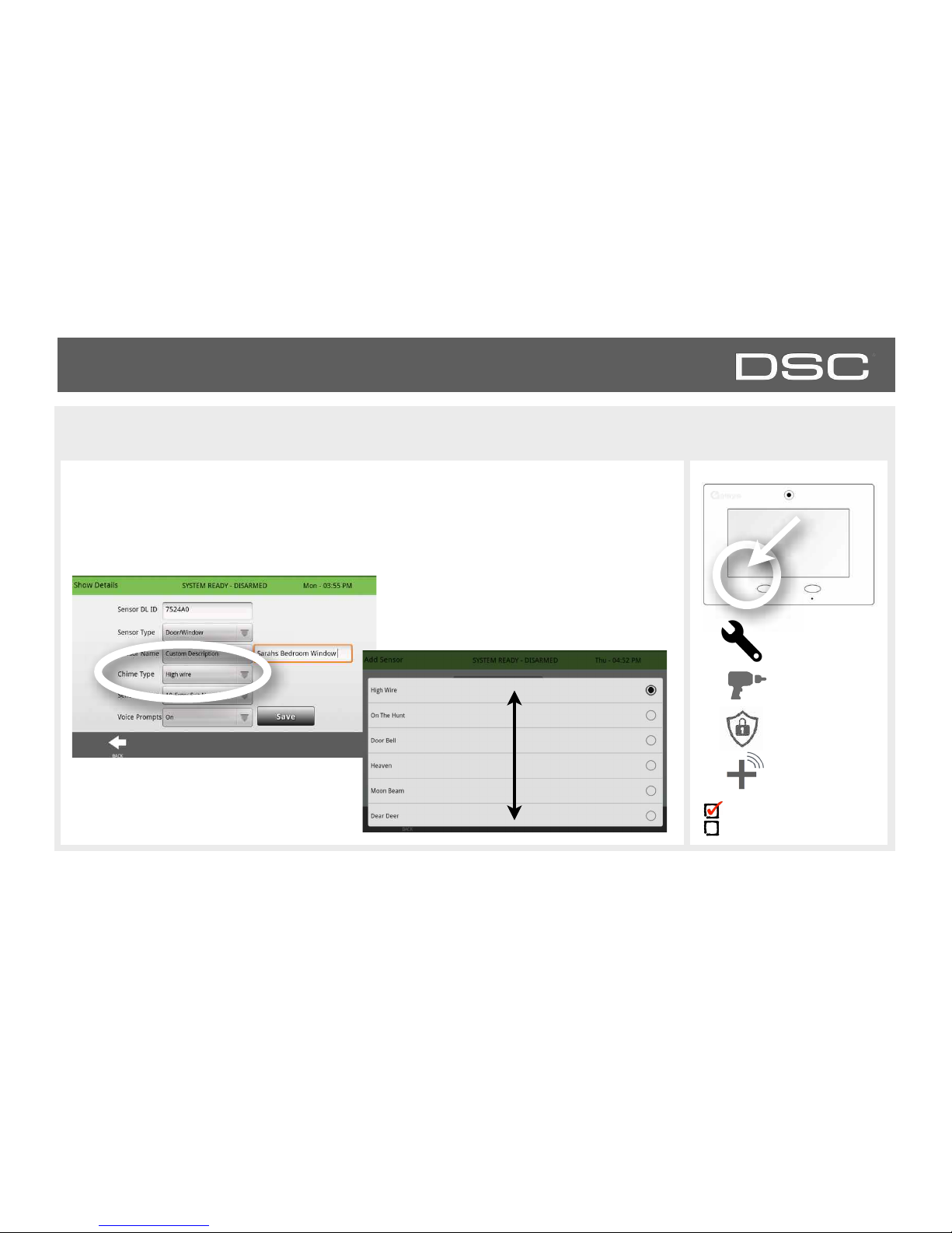
INSTALLATION
CHIME TYPE
FIND IT
Settings
Installation
Security Sensors
AutoLearn
Sensor
Because of the dynamic nature of the way the DSC Touch pairs and understands each
individual sensor, you can program each to have a unique chime or even turn chiming off
for that individual sensor. To customize your chime for a particular sensor touch the chime
type button and choose from the list.
Installer Code Access
Master Code Access
DSC Confidential and Proprietary Page of 29 114
© Last updated 4/29/15 All rights reserved
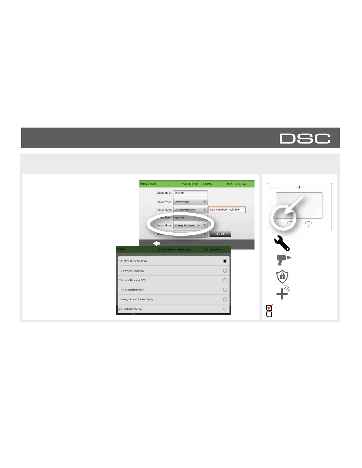
INSTALLATION
SENSOR GROUP
FIND IT
Settings
Installation
Security Sensors
AutoLearn
Sensor
Customizing the sensor group will change
the behavior of the panel. Sensor groups
are tied directly to your sensor type, so
only the groups available for that type of
sensor will be displayed. To edit sensor
group, touch the “Sensor Group” button.
You can find a full list of sensor
groups on the panel inside the
“Sensor Group” app under
“Security Sensors.”
You can also find descriptions of
how these sensor groups behave
on the following pages.
Installer Code Access
Master Code Access
DSC Confidential and Proprietary Page of 30 114
© Last updated 4/29/15 All rights reserved
 Loading...