

DSC T-LINK TL250, T-LINK TL350 Installation Manual

T-Link TL250/TL300
Network Internet
Alarm Communicator
Installation Manual
Software Version 1.20

WARNING Please Read Carefully
Note to Installers
This warning contains vital information. As the only individual
in contact with system users, it is your responsibility to bring
each item in this warning to the attention of the users of this system.
System Failures
This system has been carefully designed to be as effective as
possible. There are circumstances, however, involving fire, burglary, or other types of emergencies where it may not provide
protection. Any alarm system of any type may be compromised
deliberately or may fail to operate as expected for a variety of
reasons. Some but not all of these reasons may be:
Inadequate Installation
A security system must be installed properly in order to provide
adequate protection. Every installation should be evaluated by a
security professional to ensure that all access points and areas
are covered. Locks and latches on windows and doors must be
secure and operate as intended. Windows, doors, walls, ceilings
and other building materials must be of sufficient strength and
construction to provide the level of protection expected. A
reevaluation must be done during and after any construction
activity. An evaluation by the fire and/or police department is
highly recommended if this service is available.
Criminal Knowledge
This system contains security features which were known to be
effective at the time of manufacture. It is possible for persons
with criminal intent to develop techniques which reduce the
effectiveness of these features. It is important that a security system be reviewed periodically to ensure that its features remain
effective and that it be updated or replaced if it is found that it
does not provide the protection expected.
Access by Intruders
Intruders may enter through an unprotected access point, circumvent a sensing device, evade detection by moving through
an area of insufficient coverage, disconnect a warning device, or
interfere with or prevent the proper operation of the system.
Power Failure
Control units, intrusion detectors, smoke detectors and many
other security devices require an adequate power supply for
proper operation. If a device operates from batteries, it is possible for the batteries to fail. Even if the batteries have not failed,
they must be charged, in good condition and installed correctly.
If a device operates only by AC power, any interruption, however brief, will render that device inoperative while it does not
have power. Power interruptions of any length are often accompanied by voltage fluctuations which may damage electronic
equipment such as a security system. After a power interruption
has occurred, immediately conduct a complete system test to
ensure that the system operates as intended.
Failure of Replaceable Batteries
This system’s wireless transmitters have been designed to provide several years of battery life under normal conditions. The
expected battery life is a function of the device environment,
usage and type. Ambient conditions such as high humidity, high
or low temperatures, or large temperature fluctuations may
reduce the expected battery life. While each transmitting device
has a low battery monitor which identifies when the batteries
need to be replaced, this monitor may fail to operate as
expected. Regular testing and maintenance will keep the system
in good operating condition.
Compromise of Radio Frequency (Wireless) Devices
Signals may not reach the receiver under all circumstances
which could include metal objects placed on or near the radio
path or deliberate jamming or other inadvertent radio signal
interference.
System Users
A user may not be able to operate a panic or emergency switch
possibly due to permanent or temporary physical disability,
inability to reach the device in time, or unfamiliarity with the
correct operation. It is important that all system users be trained
in the correct operation of the alarm system and that they know
how to respond when the system indicates an alarm.
Smoke Detectors
Smoke detectors that are a part of this system may not properly
alert occupants of a fire for a number of reasons, some of which
follow. The smoke detectors may have been improperly
installed or positioned. Smoke may not be able to reach the
smoke detectors, such as when the fire is in a chimney, walls or
roofs, or on the other side of closed doors. Smoke detectors may
not detect smoke from fires on another level of the residence or
building.
Every fire is different in the amount of smoke produced and the
rate of burning. Smoke detectors cannot sense all types of fires
equally well. Smoke detectors may not provide timely warning
of fires caused by carelessness or safety hazards such as smoking in bed, violent explosions, escaping gas, improper storage of
flammable materials, overloaded electrical circuits, children
playing with matches or arson.
Even if the smoke detector operates as intended, there may be
circumstances when there is insufficient warning to allow all
occupants to escape in time to avoid injury or death.
Motion Detectors
Motion detectors can only detect motion within the designated
areas as shown in their respective installation instructions. They
cannot discriminate between intruders and intended occupants.
Motion detectors do not provide volumetric area protection.
They have multiple beams of detection and motion can only be
detected in unobstructed areas covered by these beams. They
cannot detect motion which occurs behind walls, ceilings, floor,
closed doors, glass partitions, glass doors or windows. Any type
of tampering whether intentional or unintentional such as masking, painting, or spraying of any material on the lenses, mirrors,
windows or any other part of the detection system will impair its
proper operation.
Passive infrared motion detectors operate by sensing changes in
temperature. However their effectiveness can be reduced when
the ambient temperature rises near or above body temperature or
if there are intentional or unintentional sources of heat in or near
the detection area. Some of these heat sources could be heaters,
radiators, stoves, barbeques, fireplaces, sunlight, steam vents,
lighting and so on.
Warning Devices
Warning devices such as sirens, bells, horns, or strobes may not
warn people or waken someone sleeping if there is an intervening wall or door. If warning devices are located on a different
level of the residence or premise, then it is less likely that the
occupants will be alerted or awakened. Audible warning devices
may be interfered with by other noise sources such as stereos,
radios, televisions, air conditioners or other appliances, or passing traffic. Audible warning devices, however loud, may not be
heard by a hearing-impaired person.
Telephone Lines
If telephone lines are used to transmit alarms, they may be out of
service or busy for certain periods of time. Also an intruder may
cut the telephone line or defeat its operation by more sophisticated means which may be difficult to detect.
Insufficient Time
There may be circumstances when the system will operate as
intended, yet the occupants will not be protected from the emergency due to their inability to respond to the warnings in a
timely manner. If the system is monitored, the response may not
occur in time to protect the occupants or their belongings.
Component Failure
Although every effort has been made to make this system as
reliable as possible, the system may fail to function as intended
due to the failure of a component.
Inadequate Testing
Most problems that would prevent an alarm system from operating as intended can be found by regular testing and maintenance. The complete system should be tested weekly and
immediately after a break-in, an attempted break-in, a fire, a
storm, an earthquake, an accident, or any kind of construction
activity inside or outside the premises. The testing should
include all sensing devices, keypads, consoles, alarm indicating
devices and any other operational devices that are part of the
system.
Security and Insurance
Regardless of its capabilities, an alarm system is not a substitute
for property or life insurance. An alarm system also is not a substitute for property owners, renters, or other occupants to act
prudently to prevent or minimize the harmful effects of an emergencysituation.

Table of Contents
Section 1: Introduction 1
1.1 Operating Modes . . . . . . . . . . . . . . . . . . . . . . . . . . . . . . . . . . . . . . . . . . . . . . . . . . . . 1
1.2 Specifications . . . . . . . . . . . . . . . . . . . . . . . . . . . . . . . . . . . . . . . . . . . . . . . . . . . . . . . 2
Section 2: Quick Start 3
2.1 Installation . . . . . . . . . . . . . . . . . . . . . . . . . . . . . . . . . . . . . . . . . . . . . . . . . . . . . . . . . 3
2.2 Testing . . . . . . . . . . . . . . . . . . . . . . . . . . . . . . . . . . . . . . . . . . . . . . . . . . . . . . . . . . . . 3
2.3 Resetting to Factory Defaults . . . . . . . . . . . . . . . . . . . . . . . . . . . . . . . . . . . . . . . . . . . 4
Section 3: Bell Follower Installation (Mode 1) 5
Section 4: Stand alone Installation (Modes 2 & 3) 6
4.1 Stand alone Mode 2 Configuration . . . . . . . . . . . . . . . . . . . . . . . . . . . . . . . . . . . . . . . 6
4.2 Input Expander Mode 3 Configuration . . . . . . . . . . . . . . . . . . . . . . . . . . . . . . . . . . . 6
Section 5: Standard Installation (Mode 4) 7
5.1 Input Expander Mode 3 Configuration . . . . . . . . . . . . . . . . . . . . . . . . . . . . . . . . . . . 6
5.2 Standard connection with PC4020(CF)/PC5020(CF). . . . . . . . . . . . . . . . . . . . . . . . . 7
5.3 Wiring T-Link to a DSC compatible Control Panel . . . . . . . . . . . . . . . . . . . . . . . . . . 8
5.4 UL Listed Commercial Fire Systems . . . . . . . . . . . . . . . . . . . . . . . . . . . . . . . . . . . . . 8
Section 6: DVACS Installation (Mode 5) 9
6.1 DVACS Panel Installation . . . . . . . . . . . . . . . . . . . . . . . . . . . . . . . . . . . . . . . . . . . . . 9
6.2 DVACS Events . . . . . . . . . . . . . . . . . . . . . . . . . . . . . . . . . . . . . . . . . . . . . . . . . . . . . . 9
Section 7: TL300 Telephone Simulation 11
7.1 TL300 Panel Installation . . . . . . . . . . . . . . . . . . . . . . . . . . . . . . . . . . . . . . . . . . . . . . 11
7.2 T-Link TL300 Operation. . . . . . . . . . . . . . . . . . . . . . . . . . . . . . . . . . . . . . . . . . . . . . 11
Section 8: T-Link Operation 12
8.1 Remote Control . . . . . . . . . . . . . . . . . . . . . . . . . . . . . . . . . . . . . . . . . . . . . . . . . . . . 12
8.2 Programming . . . . . . . . . . . . . . . . . . . . . . . . . . . . . . . . . . . . . . . . . . . . . . . . . . . . . . 12
8.3 IP Address . . . . . . . . . . . . . . . . . . . . . . . . . . . . . . . . . . . . . . . . . . . . . . . . . . . . . . . . 12
8.4 Port Usage Table . . . . . . . . . . . . . . . . . . . . . . . . . . . . . . . . . . . . . . . . . . . . . . . . . . . 12
8.5 Integrated Call Directions . . . . . . . . . . . . . . . . . . . . . . . . . . . . . . . . . . . . . . . . . . . . 13
8.6 Status Indicators . . . . . . . . . . . . . . . . . . . . . . . . . . . . . . . . . . . . . . . . . . . . . . . . . . . . 13
8.7 Test & Troubleshooting . . . . . . . . . . . . . . . . . . . . . . . . . . . . . . . . . . . . . . . . . . . . . . 14
Section 9: Programming Guide 15
9.1 Basic Programming (PC4020 Control Panel) . . . . . . . . . . . . . . . . . . . . . . . . . . . . . . 15
9.2 Basic Programming (PC5020 Control Panel) . . . . . . . . . . . . . . . . . . . . . . . . . . . . . 15
9.3 T-Link DVACS Programming . . . . . . . . . . . . . . . . . . . . . . . . . . . . . . . . . . . . . . . . . 16
9.4 T-Link TL300 Programming. . . . . . . . . . . . . . . . . . . . . . . . . . . . . . . . . . . . . . . . . . . 17
Section 9: Programming Descriptions (Advanced) 18
Section 10: Programming Worksheets 26
Glossary 30
Appendix A: T-Link TL250 Compatibility Chart . . . . . . . . . . . . . . . . . . . . . . . . . . . 32
Appendix B: T-Link TL300 Compatibility Chart . . . . . . . . . . . . . . . . . . . . . . . . . . . 33
Appendix C: T-Link Tl250/Tl300 Events . . . . . . . . . . . . . . . . . . . . . . . . . . . . . . . . . 34
Appendix D: Contact ID Reporting Codes . . . . . . . . . . . . . . . . . . . . . . . . . . . . . . . . . 35
Appendix E: Network Protection . . . . . . . . . . . . . . . . . . . . . . . . . . . . . . . . . . . . . . . . 40


Section 1: Introduction
T-Link TL250/TL300
The T-Link TL250/300 modules are network internet communicators that send alarm system
information to a central station receiver. The module is pre-programmed with the most commonly used settings for quick installation. Default options can be custom programmed using TLink Console software if required.
T-Link TL300
The T-Link TL300 connects directly to the telephone output of a control panel and simulates a
telephone connection, providing a TCP/IP connection that sends predefined Contact ID codes
to the central station. The T-Link TL300 on-board zones can be used as in mode 2 (4-zone
stand-alone) and mode 3 (12-zone stand-alone). Modes 1 and 5 are not supported.
Software Version 1.0
• Supports TL250 and Modes 1, 2, 3 and 4 only.
Software Version 1.10
• Supports TL250, includes Version 1.0 options and Mode 5, TL250 DVACS panel conversion (Canada only). Corresponding version numbers for SG DRL3-IP and T-Link Console
are required to ensure compat ibility (i.e., SG DRL3-IP v1.10 and T-Link Console v1.10 are
required for corresponding T-Link TL250 v1.10).
NOTE: For DVACS mode an SG-DRL3-IP v1.10 receiver line card is required to communicate
with the T-Link TL250 v1.10 or higher.
• Account code extended from 6 to 10 digits.
Software Version 1.20
• Supports TL250 and TL300 and all Version 1.10 options.
• Supports new zone type ‘98’ Panel Absent.
• Supports basic programming from an LCD 5500 Keypad.
• Default Installer code has changed from CAFE to 5555 for this software version
1.1 Operating Modes
Mode 1: Bell Follower (TL250 only)
In Mode 1, the T-Link TL250 monitors the Bell Output of a control panel. The system identifies the Bell Output cadence and transmits the corresponding Fire or Burglar alarm reporting
code to the central station. Refer to section 3 for details
Refer to the appropriate control panel Installation Manual.
NOTE: Do not use Mode 1 for UL or ULC listed installations.
Mode 2: 4-Zone Panel (TL250 and TL300)
In Mode 2, the system is configured for 4-zone, stand alone oper atio n. Refer to section 4.1 fo r
details.
Mode 3: 12-Zone Panel (TL250 and TL300)
If the T-Link TL250 detects a PC5108 expander card on power up it will automatically configure
itself for 12-zone standalone operation with normally open loops. Refer to section 4.2 for details.
NOTE: In modes 2 & 3, the connections between the PC5108 inputs or T-Link TL250 inputs and
the alarm control unit outputs (relay contacts) shall be done in metal conduit, within 20 ft.
Stand-alone operation will still require the inputs to be programmed with the desired alarm
types.
Mode 4: Standard Mode (TL250 only)
In standard mode, the system is configured as a communicator with a compatible DSC alarm
panel: Models PC4020, PC4020CF, PC5020 or PC5020CF. Refer to section 5 for details.
1

Mode 5: DVACS®* Mode (V1.10 or later)(TL250 only)
In DVACS mode, the system is configured as a communicator with a compatible DVACS
alarm panel. Refer to section 6 for details. Refer to appendix C for a list of compatible
DVACS panels and modules.
NOTE: T-Link TL250 zone events are transmitted using the standard T-Link SIA protocol.
DVACS generated events are transmitted using the DVACS protocol.
NOTE: DVACS Mode 5 is used in ULC listed installations.
* DVACS is a registered trademark of Electro Arts Ltd. Scarborough Ontario, Canada
1.2 Specifications/Requirements
The maximum allowable current draw from a compatible DSC panel on the Aux terminal
Output is 500 mA @ 12V
DC. Operational current draw of the T-Link TL250 is 250 mA. The
T-Link TL250 module has 2 switched negative programmable outputs (50 mA @ 12 V
Specifications
Input Voltage:12 VDC
Input Current: T-LINK TL250 Max current draw: 275mA
Dimensions: 3.25” × 5.25” (8.3 cm × 13.3 cm)
Operating Temperature: 32°-122°F (0°-49°C)
Output Protocols: UDP/IP 10/100 BaseT half duplex, TCP/IP for Console and DLS commu-
nications
Input Protocols: PC-Link (SIA format), DVACS (V1.10 and higher), Contact ID protocol.
(TL300 Only)
Digital Inputs: 4-digital inputs (can be increased to 12 using the PC5108)
Connectors: 4-pin header for the PC-Link and RJ-45 for Ethernet, DVACS adaptor
(DVACS kit only)
Programming: Panel keypad, console on the RS232 or remote T-Link console.
Network: Ethernet LAN/WAN 10 BaseT or 10/100 BaseT
E-mail: sends alarm messages to maximum 2 E-mail addresses
(NOT available for DVACS installations)
Downloading Support for DSC Panels:DLS-3 and/or System Administrator software
Multiple Central Stations: primary and backup via phone line*
(NOT available for DVACS installations).
Call Direction Options: primary or backup communicator using panel call direction
(NOT available for DVACS installations).
Approval Listings: FCC, IC, CE
UL (Grade of Service AA, Encr ypted Line Security)
ULC (Signal Channel Security Level 4/5)
*NOTE:This manual shall be used with the Installation Manual of the associated Alarm Controller for installation.
NOTE: For UL Listed fire installations, shared on-premises communication equipment is
required to be UL Listed for Information Technology Equipment. The communication medium
between protected property and communications service provider must be for the exclusive
use of the protected property and not shared with other communications service provider
subscriber.
NOTE:When a hub or router/gateway is used on the premises with the T-Link TL250, 24-hr.
standby power is required for these devices (i.e., UL listed UPS, battery backup).
NOTE:This equipment (T-Link TL250) shall be installed and used within an environment that
provides the POLLUTION DEGREE MAX 2 and OVERVOLTAGES CATEGORY II NON-HAZARDOUS LOCATIONS, indoor only. The equipment must be FIXED and permanently connected,
and is intended to be installed by SERVICE PERSONS (i.e., having the appropriate technical
training and experience necessary to be aware of hazards which that person may be exposed
to in performing the task, and of measures to minimize the risks to that person or other persons).
T-LINK TL300 Max current draw: 360mA
CAUTION
Ethernet communication lines must be connected to an approved (acceptable to local authorities) type NID (Network Interface Device) before leaving the premises (e.g., UL installations,
UL60950 Listed NID).
DC).
2

Section 2: Quick Start
2.1 Installation
1. Determine the Operating Mode Required
The operating mode (Modes 1, 2, 3, Standard Mode, or DV ACS Mode) will determine how the
unit is to be wired.
2. Determine the Mounting Location
Select a mounting location in a dry, protected area at least 30 cm. away from physical contact
with any person. Refer to page 34, appendix C, for Network Protection details.
NOTE: Do not exceed the following recommendations for wire run distances
• Input wiring should must be minimum 22 gauge quad (0.5mm). Two pair twisted is preferred.
• PC5108, or zone wiring must not exceed 1,000' (305m) (in wire length) from the T-Link
module.
• Shielded wire is not necessary unless wires are run in an area that may present exce s si v e
RF noise or interference.
• Refer to section 9, Programming Descriptions, section [36] for zone wiring details.
3. Route Wiring to Mounting Location
Route wiring from the hard wired zones or control panel as required.
NOTE: Route wiring through conduit to a junction box if possible.
4. Mount the T-Link TL250/300 Panel
2.2 Testing
Mode 4, Standard Mode: Ensure the panel is programmed to use the T-Link TL250 in accordance with the settings outlined in section 8, Programming Guide. Simulate Burglar and Fire
Zone violation on the DSC alarm panel. Verify that the T-Link TL250 transmits the events to
the central station.
Mode 1: Ensure the T-Link is programmed in accordance with the settings outlined in Sections
9, Programming Descriptions. Simulate Burglar and Fire Zone violation on the alarm panel.
Verify that the T-Link TL250 transmits the events to the central station.
Modes 2, 3 and 5 (DVACS): Simulate Inputs violations in accordance with the settings outlined in Sections 9, Programming Descriptions. Verify that the T-Link TL250 transmits the
events to the central station.
TL300 Simulated Phone: Ensure the T-Link TL300 Input 1 is programmed in accordance
with the TL300 settings outlined in Sections 9, Programming Descriptions. Simulate Burglar
and Fire Zone violation on the alarm panel. Verify that the T-Link TL300 transmits the associated Contact ID code to the central station.
3

2.3 Resetting to Factory Defaults
Hardware Defaults (all modes)
• Remove Power from the T-Link TL250/TL300; disconnect battery and control panel if
applicable
• Disconnect all wiring from the PGM1 and IN1 terminals. Connect a jumper wire between
the PGM1 and IN1 terminals
• Apply power to the system
• Remove power from the T-LINK TL250/TL300 for approximately 20 seconds
• Reconnect all original wiring and reapply power to the T-Link TL250/TL300.
• Test System - refer to section 2.2
NOTE: A restart is required for the programming changes to take effect. Allow up to 15 seconds for a restart.
Mode 4:
In mode 4, the T-Link can be Defaulted through the panel keypad:
• Enter section 999 of the T-Link TL250
• Enter 00 to default the unit to factory settings
• Enter 55 to restart the unit.
2.4 LCD 5500 Programming
All Modes (Software version 1.2 only)
Local programming of basic options can be done through a standard DSC Power LCD keypad.
Connect the keypad on the T-Link Keybus terminals. Access to programming mode uses the
same code as the console (default is '5555').
NOTE:Programming mode access can be done only on power up for 30 seconds, and only
if the reset to factory default is not activated.
• Access the Installer mode using [*][8], followed by the installer code.
NOTE:The [*] and [#] keys are not supported to re-enter installer code in the event of an
incorrect entry. All keys will be ignored if the correct sequence following [*][8] is not
entered.
• Four Programming Sections are available and will be displayed in the sequence indicated
below. See section 9 for details
[001] T-Link IP Address:
|___|___|___|.|___|___|___|.|___|___|___|.|___|___|___|
[003] T-Link Account Code
|___|___|___|___|___|___|___|___|___|___|
[007] Primary Receiver IP Address
|___|___|___|.|___|___|___|.|___|___|___|.|___|___|___|
[007] Primary Receiver Gateway IP Address
|___|___|___|.|___|___|___|.|___|___|___|.|___|___|___|
When programming is completed, press the "#" key to save changes and exit programming
mode. A 2-minute timing delay begins when entering the programming mode. At the end of the
timing delay T-Link will exit program mode and save the changes made regardless of where
the programmer is in the programming sequence.
• Remove power from the system
• Reconnect all original wiring and reapply power to the system
• Test System - Refer to section 2.2
NOTE: A restart is required for the programming changes to take effect. Allow up to 15 seconds for a restart.
4
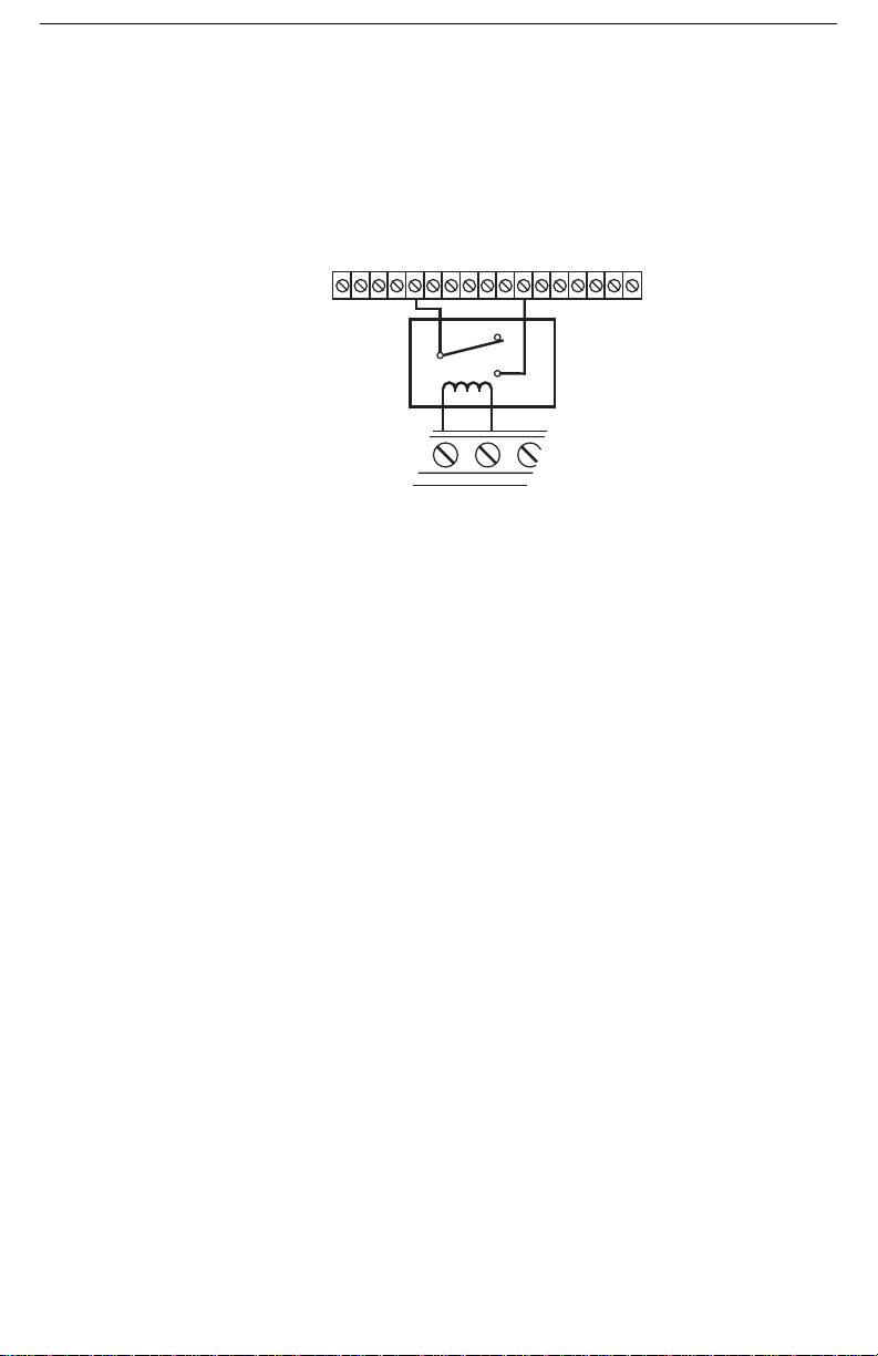
Section 3: Bell Follower Installation (Mode1)
BELL+ BELL-
Alternate connection for
Control Panels where Bell
switches High
Relay
Com
NC
NO
+12V GND YX RX GND RE D YE L G RN PGM1 PGM2 IN1 GND GNDIN2 IN3 IN4 EARTH
3.1 Setup and Installation
3.1.1 Bell Follower Installation (Mode 1)
Install the T-Link TL250 in a DSC enclosure (model PC5003C) when used in a Bell Follower
configuration. Refer to section [036][99].
Connect the 12V
NOTE: Bell Follower mode can not be used in UL or ULC listed installations.
Refer to options [062] through [065].
DC and GND terminals to the external 12V power source.
5
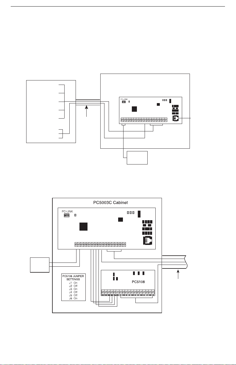
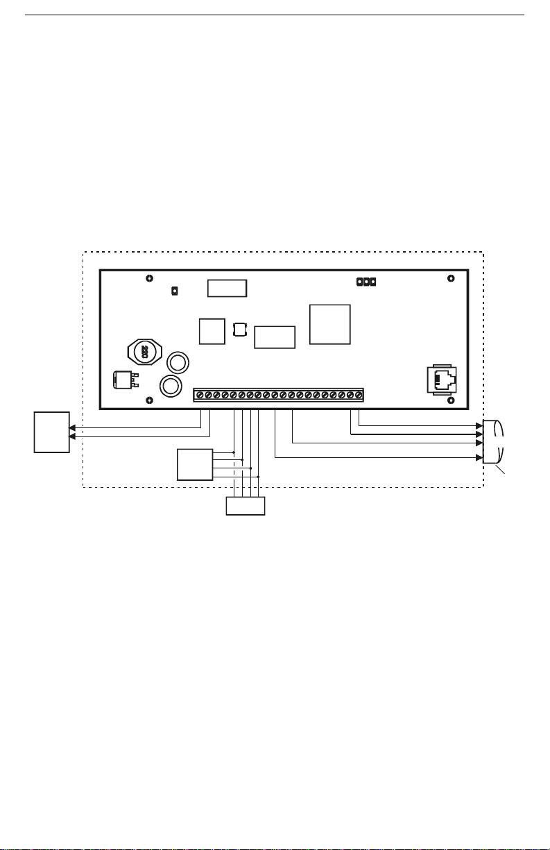
Section 4: Stand-alone Installation (Modes 2&3)
PC5003C Cabinet
Note: Wiring between the control panel and the T-Link
TL250 must be enclosed in metal conduit.
Outputs
Input
+12V GND TX RX GND RED BLK YEL GRN IN1 IN2 IN3 IN4 EARTHGND GND1 PGM 2
LK
ACT
SPD
STAT
T-LINK TL250
12V 275mA
UL Listed
Power Supply
CAT5 Cable
(shielded)
10/100 BaseT
Network
PGM1 Trouble Output
IN1 - IN4
Zone Inputs
(Not supervised)
Fire/Burglary
Alarm Panel
Metal Conduit
(20ft max.)
J6
J4
J5
J1
J2 J3
+12V
GND
GNDRED BLK
YEL
GRN GNDIN1 GND
EARTH
IN3 IN4IN21 PGM 2
TX RX
LK
ACT
SPD
STAT
Cat5
Network
10/100 BaseT
T-LINK TL250
12V 275mA
UL Listed
Power Supply
PGM1 Trouble Outputs
Metal
Conduit
(20ft max.)
Z1 - Z8 Inputs (NO/NC)
(Not supervised)
IN1 - IN4 Inputs (NO/NC)
(Not supervised)
Connect
to Fire/Burg.
Alarm
Panel
Install the T-Link TL250 in a DSC enclosure (model PC5003C) when used in a stand-alone configuration or with the PC5108 module.
Connect the 12V
NOTE: For UL Listed installations, the power supply used must be UL Listed for the application.
4.1 Stand alone Mode 2 Configuration
4.2 Input Expander (Mode 3 Configuration)
To expand from the 4-zone inputs a PC5108 must be connected to the T-Link. Connect the
Keybus from the PC5108 to the Keybus of the T-Link TL250. Any devices that require 12V
motion detectors, glass break detectors, etc., will require an external 12V
DC and GND terminals to the external 12V power source.
DC,
DC power supply .
6
Section 5: Standard Installation (Mode 4)
+12V GND TX RX GND RED BLK YELGRN PGM1PGM2 IN1 GND IN2 IN3 GND IN4 EARTH
Network
PC-LINK
PC-LINK
SUPERVISED
SUPERVISED
STAT
Network Connection
Use only CAT5 cable
(300ft / 100m max.)
Supervised
WARNING!: Do not connect transformer
to receptacle controlled by a switch. The
transformer must be UL Listed and have
a restraining means.
V = 12VDC
I = 250mA (275mA with PGM or PC5108)
RED
BLK
+
-
LK
ACT
SPD
16.0V@40VA
5.1 Power864 and Maxsys Panel Setup and Installation
Refer to the PC4020(CF) or PC5020(CF) Installation Manuals for control panel installations.
Mount the T -Link on the side wall of the PC4050C or PC4050CR cabinet. Refer to appendix C
for Network Protection installation instructions.
Remove power from the control panel before any connections are made to the T-Link TL250.
Connect the 12V
plied cable from the T-Link TL250 white connector to the PC-Link header of the control panel.
The black wire of the PC-Link cable is pin 1 on the PC-Link header for the PC5020 v3.2 or
higher control panels. The PC-Link header is polarized on the PC4020 v3.31 or higher control
panel. Connect the e-ground to a proper earth-ground connection.
5.2 Standard Connection with PC4020(CF)/PC5020(CF)
CAUTION: All circuits are supervised and power limited. Refer to section 5.4, UL Listed Commercial Fire Systems diagram for wire routing. Do NOT route any wiring over the circuit
boards. Maintain at least 1” (25.4mm) separation between circuit board and wiring.
A minimum of 1/4” (7mm) separation must be maintained at all points between non power limited wiring and power limited wiring.
DC and GND terminals to the panel auxiliary power output. Connect the sup-
7
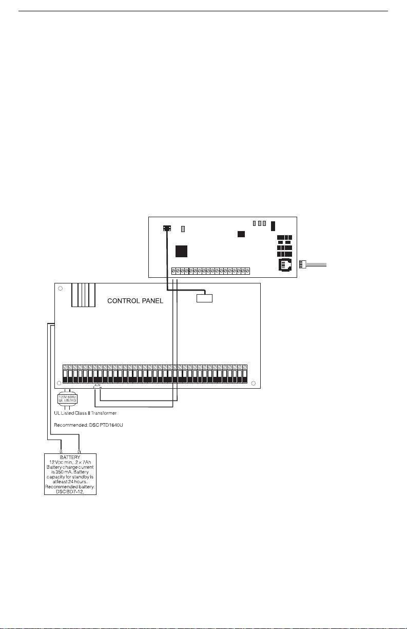
5.3 Wiring T-Link to a DSC Compatible Control Panel
• Secure the T-Link module to the side of the cabinet using the supplied standoffs.
• With AC power and battery disconnected removed from the DSC control panel, wire the T-Link to
the panel using 4 wires from the PC-Link of the panel to the “PANEL” connector on the T-Link.
• Wire the panel's AUX+ and - to 12V
DC and GND terminals of T-Link.
• Apply AC and DC to the main control panel. Both the T-Link and the panel should power up.
• Do the necessary programming that is required.
NOTE: If a Bell/Siren will not be used, wire the Bell/Siren terminals on the panel with a 1000
ohm resistor. For Commercial Fire installation, when a bell/siren is used in the application, it
should be connected to the DSC module PC4702BP. Refer to the PC4020 Installation manual.
The keypad or any other accessory connected to the Combus shall be connected within 3 feet
/ 0.9 m and in conduit.
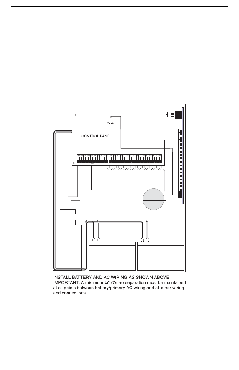
5.4 Battery and AC Power Lead Routing for
UL Listed Commercial Fire Systems
GND
+12V
T-Link board must be mounted on the side of the cabinet. Refer to
the mounting instructions in the associated Installation Manual.
8

Section 6: DVACS Installation (Mode 5)
DVACS Panel
Installed in Cabinet
ULC Listed Installation
DVACS RS-232
TX, RX, GND
12/24V
DC
Red, Blk
F1/F2
DVACS
Subset
MLR2
with DVL2A
DV1660
DVACS
Network
DVACS
Network
SG-DVL2A
Tx
Rx
ALARM
ACK./
TROUBLE
SELECT
WATCHDOG
WATCHDOG
SELECT
TROUBLE
ACK./
ALARM
Rx
Tx
CARRIERCARRIER
FUNCT. FUNCT.
BACKSPACE
Rx
ESCAPE
TROUBLE
OPTION
ACK.
ENTER
Tx
SG-CPM2
AC
F E D
7 8 9 C
650B
1 2 3 A
4
LAN/WAN/
Internet
LAN/WAN/
Internet
DVACS Panel
Alternate
Power Supply
Installed in Cabinet
ULC Listed Installation
DVACS cable must be run
in metal conduit & terminated
with an RJ-45 connector
RJ-45 to PC-Link Adaptor
12V Red, Blk
DC
T-Link TL250
PC 5003C Cabinet
CON5
CON2
CON1
CON1
CON3
CON3
PCLINKPCLINK
SPD ACT LNK
STAT
+12V GNDTX RX GND RED BLK YEL GRN PGM1 PGM2 IN1 GND IN2 IN3 GND IN4 EARTH+12V GNDTX RX GND RED BLKYEL GRN PGM1 PGM2 IN1 GND IN2 IN3 GND IN4 EARTH
220
System III Receiver
with DRL3-IP Line Card
RRLLL = 02345
IP Account = 010A000034
DVACS Automation Protocol
1 Digit 101A 034...
2 Digits 1010A 034...
3 Digits 10100A 034...
SIA Automation Protocol
1 Digit S025[#000034|...
2 Digits S0245[#000034|...
3 Digits S02345[#000034|...
ID=34
Account = 010A000034
RRLL = 010A
For Decimal Account#
Account = 010A000056
Typical T-Link TL250/DVACS Installation
ULC Listed Power Supply
with Battery Backup
DV1660
6.1 DVACS Panel Installation.
Remove power from the control panel before wiring connections to the T-Link TL250 module.
Connect the 12V
DVACS cable from the T-Link TL250 Adaptor on the PC-Link header to the DVACS connector on the control panel. Connect the e-ground to a proper earth-ground connection.
In a typical DVACS Installation, a DVACS panel is connected to an F1/F2 subset that communicates the alarm information to the central station comprising an SG MRL2 receiver with an
SG DVL2A module installed.
To send DVACS Alarm information over the internet, the T-Link TL250 performs the equivalent functions of the F1/F2 subset and the polling function of the SG DVL2A. DVACS alarm
information is sent to the T-Link TL250 by connecting the existing RJ-45 terminated cable to
the PC-Link Header on the TL250 module with an RJ-45 to PC-Link adaptor. The T-Link
transmits DVACS alarm information in the DVACS protocol and T-Link Alarm information in
the SIA protocol over the internet to a System III Receiver with SG-DRL3-IP line card
installed.
DC and GND terminals to the panel auxiliary power output. Connect the
6.2 DVACS Events
DVACS events generated on DVACS panels connected through the T-Link TL250 follow the
same protocols used on the SG-DVL2A module.
DVACS Alarms Examples
Example 1 (DVACS with receiver set as 1 digit line number)
Printer:
01 Nov 2004-11:38:22-01/02-SG -01-1-001--Burgl Alm Zn#02
Computer:
Example 2 (DVACS with receiver set as 3 digits line number)
1011 001 A 02
Printer:
01/02-SG -01-001-014--Burgl Alm Zn#13
Computer:
101001 014 A 13
9

SIA
DVACS Alarms Examples
Example 1 (DVACS with receiver set as 1 digit line number)
Printer:
01 Nov 2004-13:50:51-01/02-SG -01-1-0456--Fire Alm Zn999
Computer:
3011 0456FA 999
Example 2 (DVACS with receiver set as 3 digits line number)
Printer:
01 Nov 2004-13:51:03-01/02-SG -01-001-0456--Medical Alm Zn001
Computer:
3011 0456MA 001
Additional Events:
If the T -Link TL250 trans mitter does not receive polls (response) from the panel, the T-Link will generate the events previously generated by the SG-DVL2A for DVACS panel and restoral.
SIA
Printer:
01 Nov 2004-13:50:51-01/02-SG -01-1-001--Account Absent
Computer:
3011 0001YC 000
Printer:
01 Nov 2004-13:50:51-01/02-SG -01-1-001--Account Present
Computer:
3011 0001YK 000
Standard
Printer:
01 Nov 2004-13:50:51-01/02-SG -01-1-001--IDcde IncResp
Computer:
1011 001 A 0A
Printer:
01 Nov 2004-13:50:51-01/02-SG -01-1-001--IDcde Restore
Computer:
1011 001 R 0A
NOTE: The SG-DRL3-IP will use 10-digit account identifications in it's IP table for DVACS
transmitters. The first four digits represents the receiver and line number originally used on
the SG-DVL2A and are programmed as the first four digits of the T-Link account (refer to
appendix F of SG-DRL3-IP Installation Manual).
NOTE:If the automation protocol in the form of 1RRL, 3RRL is required when using the DRL3IP in the DVACS configuration, set DRL3-IP Option [11] =1 and CPM3 Options [10] & [11] = 03
10
Section 7: TL300 Telephone Simulation
CON5
SPD ACT LNK
STAT
+12V GND TX R X GND RED B LK YEL GRN PGM 1 PGM2 IN1 G ND IN2 IN3 GN D IN4 EARTH T1 R1
T-Link TL300
(Refer to al arm panel manu facturers doc umentation)
Note: Do NOT con nect the alarm panel or T-link TL300 to telep hone line
Temporary connection of Keypad for programming
of T-Link during fi rst 30 seconds of power up shown
Configure zone as zone definition 98 (see section [036]-[047] Option [98]
To Tip and Ring on Alarm Panel
12V 360mA
UL Listed
Power Supp ly
or
Pane l Aux
12VDC
PC5108
(optional)
LCD5500
Keypad
PC5003 Cabinet
7.1 TL300 Panel Installation.
• Secure the T -Link module to the side of the cabinet of the control panel or ins ta ll the T-Link TL300
in a DSC enclosure (model PC 5 0 03C). Refer to Appendix B: T-Link TL300 Compatibility Chart
for a list of panels supported
• With AC power and battery disconnected removed from the control panel, connect the T-L300 to
the RJ31 phone jack from the panel to the RJ31 connector on the T-Link.
• Wire the panel's 12V
Listed Power supply.
• Wire the panel's Ti p and Ring terminals to the T1 and R1 terminals of T-Link TL300.
• Apply AC and DC to the main control panel. Both the T-Link and the panel should power up.
• Do the necessary programming that is required.
DC and GND terminals of T-Link or Power unit with a 12VDC 225 mA UL
Connect PGM1 to panel zone to indicate network l oss configure as TLM or FTC
7.2 T-Link TL300 Operation
Communication events between the panel, T-Link and the Central Station receiver are as follows:
• When an alarm triggers, the panel goes off-hook
• The T-Link module sends a dial tone to the panel
• The Panel dials the telephone number of the central station
• The T-Link detects the DTMF dialing and stops sending the dial tone.
• The T-Link sends a request to the Receiver.
• The Receiver responds with the command to the T -Link to generate the corresponding handshake.
• After receiving the handshake, the Panel transmits the alarm message in DTMF Contact ID format
• The T-Link decodes and transforms DTMF digits into an IP packet and sends it to the Receiver
over IP.
• The Receiver acknowledges alarm and sends command to the T-Link to generate a corresponding
kiss-off signal.
• After the T-Link generates kiss-off, the Panel goes on-hook if no more alarms need to be sent.
11
Connect to
Alarm Panel
Metal Conduit
20 ft(6m) max
 Loading...