

DSC PowerSeries Neo, TL8803GI-EU User Manual
TL8803GI-EU Dual Path Controller
WARNING: This manual contains information on limitations regarding product use and function and
information on the limitations as to liability of the manufacturer. The entire manual should be carefully
read.


Table of Contents
Warning: Installer Please Read Carefully 3
Alarm.com introduction 5
IP/HSPA 3G module - TL8803GI-EU 5
Contact information 6
Features 6
Communicator ratings 6
Communicator compatibility 7
Installation 8
Tools and supplies required 8
Step 1: Enable module 9
Step 2: Connect the TL8803GI-EU 9
1: Connect data bus 9
2: Connect power 10
3:Connect the PC-Link cable 10
4: Connect Ethernet (optional) 10
5: Connect external antenna (optional) 10
6: Power up 11
Step 3: Verif y installer code to activate Alarm.com module 11
Step 4: Perform dual-path test (module registration) 11
Step 5: Allow module to auto-program 11
Enroll Alarm.com Image Sensor 11
Panel settings 12
Central station and telephone line settings 12
Troubleshooting 15
Module status information 15
Troubleshooting LEDs 15
LED functions 16
LED details 16
LED L1 (red) 16
LED L2 (yellow) 17
LED L3 (yellow) 17
LED L4 (green) 17
LED L5 (yellow) 18
Various module states (modes) 18
Improving wireless signal strength 19
Walking the customer through new user setup on the web 19
Interactive Service Menu 20
Interactive menus 20
Installer programming 20
User functions 20
Limited Warranty 22
End User License Agreement 22
Regulatory Inf ormation 24
- 2 -

Warning: Installer Please Read Carefully
Note to installers
The warnings on this page c ontain vital information. As the only individual in c ontact with system use rs, it is the installer’s re sponsibility to
bring eac h item in this warning to the attention of all use rs of this system.
System f ailures
This system has been ca refully designed to be as eff ective as possible.
There are circ umstance s, however, involving fire, burglar y, or other
types of emergencies where it ma y not pr ovide protec tion. Any alarm
system of any type may be compromised deliber ately or ma y fail to
opera te as expe cte d for a variety of re asons. Some, but not all, of the
rea sons may be:
Access by intruders
Intruders may enter through a n unprotected access point, circumvent a
sensing device, evade de tec tion by moving through an are a of insufficient cove ra ge, disconnect a warning device, or interfe re with or prevent the proper operation of the system.
Component failure
Although e ver y eff ort has been made to make this system as re liable as
possible, the system may fa il to func tion as intended due to the failure
of a component.
Compromise of radio frequency ( Wireless)
A device 's signals may not rea ch the re ce iver under all circumstances,
which could include: metal objects placed on or near the radio path,
delibera te jamming or other inadver tent radio signal interfe rence.
Criminal knowledge
This system conta ins se cur ity f eatures which we re known to be effe ctive at the time of manufac ture. It is possible for persons w ith c riminal
intent to deve lop techniques which reduce the ef fectiveness of these
fea tures. It is important tha t your security system be re viewe d periodically to e nsure tha t its features remain ef fective and that it is
updated or replac ed if it is found that it doe s not pr ovide the protec tion
expected.
Failureof replaceable batteries
This system’s wireless transmitters have been designed to provide severa l year s of battery life unde r normal conditions. The expe cted battery life is a function of the de vice e nvironment, usage, a nd type.
Ambient conditions such a s high humidity, high or low temper ature s, or
large tempera ture fluc tuations ma y reduc e the expecte d battery life.
While ea ch transmitting device ha s a low battery monitor which identifies when the batter ies need to be r eplac ed, this monitor may fail to
opera te as expe cte d. Regular testing and maintenanc e will keep the system in good oper ating condition.
Inadequate installation
A secur ity system must be installed pr operly in orde r to provide
adequate protection. Every installation should be e valuated by a secur ity professional to ensure tha t all a cc ess points a nd are as ar e cove re d.
Locks and latches on windows and doors must be secure and opera te
as intended. Windows, doors, wa lls, c eilings and other building mate rials must be of suff icient strength and construc tion to provide the le vel
of protec tion e xpec ted. A re evaluation must be done during a nd afte r
any construc tion a ctivity. An evaluation by the fire a nd/or police depa rtment is highly rec ommended if this se rvice is ava ilable.
Inadequate testing
Most problems that would pr eve nt an alarm system f rom opera ting as
intended ca n be found by regula r testing and maintenanc e. The c omplete system should be tested wee kly and immediately after a break-in,
an attempted bre ak- in, a fire, a storm, an e arthquake, an acc ident, or
any kind of construction activity inside or outside the premises. The testing should include all sensing de vices, keypads, consoles, alarm indicating devices, and any other operational devices that are part of the
system.
Insufficient time
There may be circumstance s when the system will ope rate as intended,
yet the occupants will not be protec ted from an emerge ncy due to their
inability to respond to the warnings in a timely manner. If the system is
remotely monitored, the re sponse may not occur in time to protect the
occupants or their belongings.
Motion detectors
Motion detectors can only detect motion within the designated areas as
shown in their respective installation instruc tions. The y cannot discriminate be tween intruders and intended occupa nts. Motion detec tors
do not provide volumetric area protection. They have multiple beams
of detec tion and motion ca n only be detecte d in unobstruc ted ar eas
covered by these be ams. They ca nnot detect motion which occ urs
behind walls, ceilings, floors, closed doors, glass partitions, glass doors
or windows. Any type of tampering whether intentional or unintentional
such as masking, painting, or spr aying of any material on the lenses,
mirrors, windows or any other pa rt of the detection system will impair
its prope r operation. Passive infrar ed motion de tectors opera te by sensing c hange s in tempera ture. However their effec tiveness ca n be
reduc ed whe n the ambient tempera ture rises near or above body tempera ture or if ther e are intentional or unintentional sources of heat in or
near the detec tion a re a. Some of these heat source s could be heaters,
radiators, stoves, barbec ues, fireplac es, sunlight, stea m vents, lighting
and so on.
Power failure
Control units, intrusion detectors, smoke detectors and many other
secur ity de vices require a n adequate powe r supply for proper operation. If a device oper ates from batteries, it is possible for the batteries
to f ail. Even if the batter ies have not failed, they must be c harged, in
good condition a nd installed c orr ectly. If a devic e oper ates only by AC
power, any interruption, howeve r brief, will r ender that device inopera tive while it doe s not ha ve powe r. Power interruptions of any length
are often accompanied by voltage fluctuations which may damage electronic equipment such as a security system. After a power interruption
has occurre d, immediately conduct a complete system test to ensure
that the system ope rates as intended.
Security and insurance
Regardless of its ca pabilities, an alar m system is not a substitute for
proper ty or life insurance . An alar m system a lso is not a substitute for
proper ty owners, re nters, or other occupants to ac t prudently to pr event
or minimize the harmful eff ec ts of an emergency situation.
Smokedetectors
Smoke de tectors that are a part of this system may not properly alert
occupants of a fire f or a number of reasons, some of which follow.
The smoke detectors may have been improperly installed or positioned.
Smoke ma y not be able to reac h the smoke detec tors, such as when the
fire is in a chimney, walls or roofs, or on the other side of c losed doors.
Smoke de tectors may not de tect smoke from fires on another level of
the residence or building. Every fire is different in the a mount of
smoke produce d and the rate of burning. Smoke de tec tors cannot sense
all types of fires equa lly well. Smoke dete ctors may not provide timely
warning of fires ca used by carele ssness or safe ty haza rds such as
smoking in bed, violent explosions, e scaping ga s, improper storage of
flammable mate rials, overloaded electrical circ uits, c hildren playing
with ma tches, or arson. Even if the smoke detector oper ates as intended, there may be circumstances whe n there is insufficient warning to
allow all occupa nts to escape in time to avoid injury or de ath.
- 3 -

Telephone lines
If telephone lines are use d to transmit a larms, they may be out of service or busy for c ertain periods of time. Also a n intruder may cut the
telephone line or de feat its operation by more sophisticated means
which may be difficult to dete ct.
Warning devices
Warning devices such as sirens, bells, horns, or strobes may not warn
people or wa ken someone sleeping if there is an interve ning wall or
door. If wa rning device s are located on a diffe re nt level of the residence or premise, then it is less likely tha t the occupa nts w ill be a lerte d
or awa kene d. Audible warning devices may be interfer ed with by
other noise sources such as stere os, radios, televisions, air conditioners,
other applianc es, or passing tra ffic. Audible warning devices, howe ver
loud, ma y not be heard by a he aring-impaired person.
- 4 -

IMPORTANT
This installation manual shall be used in conjunction with the control panel installation manual available online
from the DSC website at www.dsc.com. All the safety instructions specified within that manual shall be
observed. The control panel is referenced as the “panel” throughout this document. This installation guide
provides the basic wiring, programming and troubleshooting information.
The alarm communicator is a fixed, wall-mounted unit, and shall be installed in the location specified in these
instructions. The alarm communicator module should NOT be installed inside of the metal alarm panel casing;
doing so will significantly impair cellular and RF (Z-Wave) transmissions. The equipment enclosure must be
fully assembled and closed, with all the necessary screws/tabs, and secured to a wall before operation. Internal
wiring must be routed in a manner that prevents:
l Excessive strain on wire and on terminal connections,
l Interference between power limited and non power limited wiring,
l Loosening of terminal connections, or
l Damage of conductor insulation.
WARNING: Never install this equipment during a lightning storm.
Safety information
The installer must instruct the system user on each of the following:
l Do not attempt to service this product. Opening or removing covers may expose the user to dangerous
voltages or other risks.
l Any servicing shall be referred to service persons only.
l Use authorized accessories only with this equipment.
l Do not stay close to the equipment during device operation.
l Do not touch the external antenna.
Alarm.com introduction
The purpose of this guide is to provide installation and operating instructions for the Alarm.com communicator
module. The following sections offer you a brief overview of its capabilities. Some capabilities and features
vary based on the Alarm.com service plan selected. Visit www.alarm.com/Dealer or contact Alarm.com for
more information.
Note: The Dual Path IP/HSPA 3G module is available in the model TL8803GI-EU.
Note: Image sensor functionality may not be enabled in all regions.
The module TL8803GI-EU contains the IP/Radio subassembly and the PC-Link to RS422 conversion interface.
The module is compatible only with NEO Alarm Control Unit models HS2128, HS2064, HS2032 and HS2016
software versions 1.1 and above.
IP/HSPA 3G module - TL8803GI-EU
The Dual Path module enables wireless reporting of all alarms and other system events from the DSC Neo control panel using an all-digital, HSPA wireless (cellular) network or an Ethernet network. The module can be
used as the primary communication path for all alarm signaling, or as a backup to a telephone connection to the
central monitoring station. The wireless alarm signaling and routing service is operated by Alarm.com. The
HSPA module also features integrated support for Alarm.com’s home automation solution with built-in
Z-Wave capabilities.
Note: Alarm.com’s home automation solution with built-in Z-Wave capabilities is not EN501311:2006/A1:2009 and EN50136-1:2012 evaluated.
- 5 -

Contact information
For additional information and support on Alarm.com modules, initial account setup, home automation, and all
other Alarm.com products and services, please visit: www.Alarm.com/dealer or contact Alarm.com technical
support at: 1-866-834-0470.
Features
l 128-bit AES encryption via cellular and Internet.
l Back up or primary cellular alarm communication and Ethernet port.
l Automatically switches to 2G (EDGE/GPRS) if HSPA (3G) service is not available.
l Full event reporting to central station.
l Cellular periodic test transmission.
l Integrated call routing.
l Panel remote uploading/downloading support via cellular or Internet.
l PC-LINK connection.
l Programmable labels.
l SIA and Contact ID (CID) formats supported.
l Signal strength and trouble display LEDs.
l Subscriber Identity Module (SIM) card included with communicator.
l Supervision heartbeats sent via cellular.
l 2-way audio capable when used with audio module HSM2955(R) - Refer to HSM2955(R) manual.
Communicator ratings
Model TL8803GI-EU
Power supply ratings
Input Voltage
Current consumption
Standby C urrent (Average Value) 100mA@12V (I)
Alarm (Transmitting) Current (Peak Value) 200mA@12V (I)
Cellular Network HSPA 3G
Operating Frequency Quad Band GSM/GPRS/EDGE + HSPA in 850/900/2100MHz
Environmental specifications
Operating Temperature -10°C to 55°C
Storage Temperature -34°C to 60°C
Humidity 93%RH non-condensing
Mechanical specification s
Dimensions 6" x 8.9" x 1.3"
Weight 365g (I)
11.3V - 12.5V DC
(provided by DSC NEO compatible control panel)
- 6 -

Communicator compatibility
Communicator
TL8803GI-EU
Receiver/
Panel
Receiver
Panel
Description
l Sur-Gard Syst em I-IP Receiver, version 1.13+
l Sur-Gard Syst em II Receiver, version 2.10+
l Sur-Gard SG-DRL3-IP, version 2.30+ (for Sur-Gard System II I Receiver)
l Sur-Gard SG-DRL4-IP version 1.20+ (for Sur-Gard System IV Receiver)
l Sur-Gard SG-DRL5-IP version 1.00+ (for Sur-Gard System 5 Receiver)
l HS2016, version 1.1+
l HS2032, version 1.1+
l HS2064, version 1.1+
l HS2128, version 1.1+
Note: Enter [*][8][Installer Code][900][000] at keypad to view the panel version number.
Products or components of products, which perform communications functions only shall comply with the
requirements applicable to communications equipment as specified in EN60950-1, Information Technology
Equipment - Safety - Part 1: General Requirements. Such components include, but are not limited to: hubs;
routers; NIDs; third-party communications service providers; DSL modems; and cable modems.
- 7 -
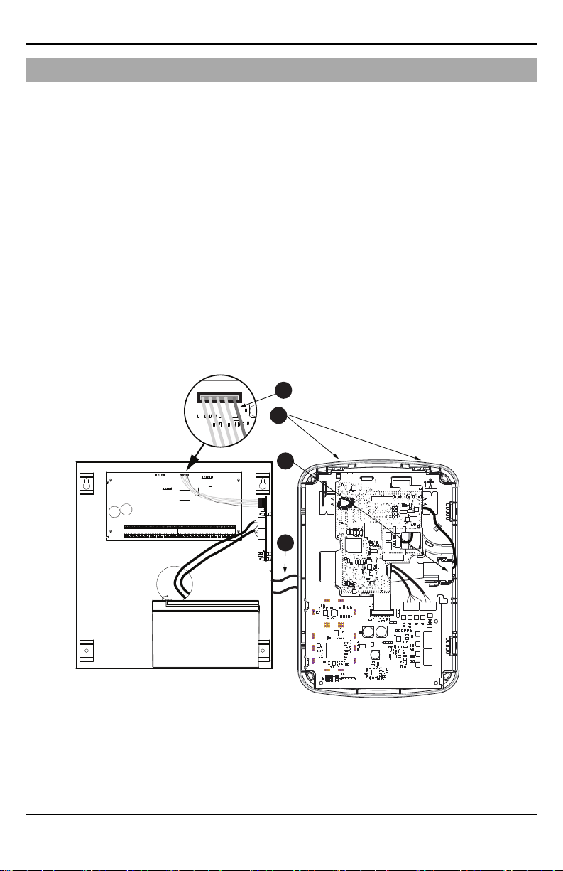
Installation
HS2016/2032/2064/2128
PCLINK_2
Alarm Controller Cabinet
HSPA Controller
A
B
D
C
INSTALLATION
Follow these guidelines during installation.
l Before affixing the communicator to a wall, verify the HSPA signal level at the installation location. On a
keypad, press and hold the 5 key for 2 seconds to view the HSPA signal level. An installation location
with a sustained signal level of two or more bars is recommended.
l Do not exceed the panel total output power when using panel power for the TL8803GI-EU module,
hardwired sensors, and /or sirens. Refer to the specific panel installation instructions for details. Only one
module can be used per panel.
l To minimize potential interference with cellular signaling, avoid mounting the communicator in areas with
excessive metal or electrical wiring, such as furnaces or utility rooms.
Do not mount the TL8803GI-EU communicator inside of the metal alarm panel enclosure.
Tools and supplies required
You will need the following tools and supplies:
l Small flat-head and Phillips screwdrivers
l Screws (included)
l Antenna (included)
l 16 pin ribbon cable (included)
- 8 -
 Loading...