

DSC TL280LE(R), LE2080(R), 3G2080(R)E, TL2803G(R)E, TL280(R)E Installation Manual

To download the full Installation Manual and register your product, please visit
dsc.com/m/29009553 scan the QR code to the right.
TL280LE(R)
Internet and LTE/HSPA Dual-Path Alarm
Communicator
LE2080(R)
LTE/HSPA Alarm Communicator
3G2080(R)E
HSPA Cellular Alarm Communicator
TL2803G(R)E
Internet and HSPA Dual-Path Alarm Communicator
TL280(R)E
Internet Alarm Communicator
Installation Guide 5.x
Warning:This manual contains information on limitations regarding productuse and function and information on the lim-
itationsas tothe liability of the manufacturer. The entire manual should be carefully read.
Please notethat notall models andfeatureslisted are available inall markets.

WARNING: Installer please read carefully
Note to Installers
The warnings on this pag e contain vitalinformation. Asthe onlyindividualin contact
with systemusers,it isthe installer’sresponsibilityto bring e ach item in thiswarning to
the attention of alluserso f thissystem.
System Failures
Thissystemh as been carefullydesigned to be ase ffective as po ssible. There are circumstances, however, involving fire, burglary,o rother types of emergencieswhere
itmay not provide protection. Any alarm system ofany type may b e compromised
deliberate lyor mayfail to operate asexpected for a varietyof reasons.Some, but
not all, of the reasons may be:
Acc ess by Intruders
Intrud ers may e nter through an unp rotected access point, circumvent a sensing
device, evade dete ction bymoving through an area of insufficient coverag e, disconne cta warning device, or interfere with or preven t the prop er operation of the
system.
Component Failure
Although every effort hasb een made tomake this systemas reliable as possible,
the systemmayfailto function a sintended d ue tothe failure o f a component.
Compromise of Radio Frequency (Wire less) Devices
Signals may not reach the receiver under all circumstances which could include
metalobjects placed on or nearthe radio path or d eliberate jammingor oth er inadvertent radiosignalinterferen ce.
Criminal Knowledge
Thissystemcontains securityfeatures whichwe re known tobe e ffective at the time
of manu facture. It is possibleforpersons with criminal inten t to develop techniques
which redu ce the effectiveness ofthese features. It isimportant that the security
systembe reviewe d periodicallyto ensure th at its features remain effective and that
itisupdated orreplaced ifit is found that it does not provide the protection expected.
Failure of Replaceable Batter ies
Thissystem’swireless tran smittersha ve been designed to provide several years of
batterylife un der normalconditions. The expected battery life isa function of the
deviceenvironment, usage, and type. Ambient conditions such as high humidity,
high orlow temperatures, or large temperature fluctua tions mayreducethe expected battery life. Whilee ach transmittingd evicehas a low batterymonitor whichidentifieswh en the batteries n eed to be replaced, this monitormay fail to operate as
expected. Reg ular testing and mainten ance will keep the system in good operating con dition.
Inadequate Installation
A security system must be installed properly in order to provide adequ ate protection. Every installation should be evaluated bya security professional to ensure
that allaccesspoints and areasare covered. Locks an d latches on windows and
doors must be secure and operate as inten ded. Windows, doo rs, walls, ceilings
and other building materials must be of sufficient strength and construction to
provide the level ofprote ction expected. A reevaluation mustb e don e during and
afterany constructionactivity. Anevaluation bythe fire and /or policede partment is
highlyrecommended if thisserviceisa vailable.
Inadequate Testing
Mostp roblemsthat would prevent an alarmsystemfromope rating a sintended can
be fou nd by regular testing and maintena nce. The complete system sho uld be
tested weekly and immediately after a break-in, an attempted brea k-in, a fire, a
storm,a n earthquake, an accident, orany kind ofconstruction activityinsideo r outside the premises. The testing should include all sensing devices, keypads, consoles,a larm indicating d evices, a nd any other operational devicesthat are part of
the system.
Insufficient Time
There may be circumstances when the system will o perate as intended, yet the
occupan ts willnot be protected froman emergencyd ue totheir inabilityto respond
to the warnings in a timely manner. If the system is remotely monitored, the
responsemaynot occurin time to protect the occupantso rtheirbelongings.
Motion Dete ctors
Motion detectors can on ly de tect motion within the designated areas asshown in
their respective installation instructions. Th ey cannot d iscriminate betwee n
intruders and intended occupants. Motion detectors do no t provide volumetric
area protection. They h ave multiple beams of detection and motion can only be
dete cted in unobstructed areas covered by these beams. They cannot dete ct
motion which occurs behind walls, ceilings, floor, closed doors, g lass partitions,
glassdoors or windows. Any type oftampering whether intentional or uninten tional
such as masking, painting, or spraying of any material on the lenses, mirrors, windowsorany other pa rt of the d etection systemwillimpairitsproperope ration.
Passive infrared motion detecto rs operate by sensing changes in temperature.
However theireffectiveness can be reduced w hen the ambient temperature rises
nearor abo ve body temperature o rifthere areintentional or unintentional sources
of heat in or ne ar the detection area . Some of these heat sources could be heat-
ers,radiators,stoves,barbecues, fireplaces, sunlight, steam vents, lighting an d so
on.
Power Failure
Controlunits, intrusion de tectors,smoke de tectorsand manyothersecuritydevices
require an adequ ate power supplyfor prop er op eration. If a deviceoperates from
batteries,itis possiblefor the ba tteries to fail. Evenif the b atte ries have not failed,
they must be charge d, in good condition and installed correctly. If a de vice op erates onlybyAC power,any interruption, howeverbrief, willrender tha t device inoperative while itdoes n ot havepower. Power interruptions of any leng th are often
accompanied by voltage fluctuations which may da mage electronic eq uipment
such as a securitysystem.After a powerinte rruption hasoccurred, immediatelycon duct a complete system test to ensure that the systemoperates asintende d.
Security and Insurance
Regardlesso f its capabilities, an alarmsystem isnota substitute for property or life
insurance. An a larm systemalsois not a substitute for property owners,renters, or
othe roccupants to act prudentlyto prevent or minimizethe harmful effects of an
emergen cysituation.
Smoke Detector s
Smokedetectorsth at a re a p art of thissystemmay not properlyalerto ccupantsof a
firefor a number of rea sons, some of wh ichfollow. The smoke detectors may h ave
been improperlyinstalledo rpositioned . Smokemaynot be ableto reach the smoke
dete ctors, such as when the fire isina chimney,wallsor roofs, o ron the other side
of closed doors. Smokedetectors maynot detect smoke fromfires on another level
of the residenceor building.
Everyfire isdifferen t in the amoun t of smoke p roduced and the rate of burning.
Smokedetectorscannot sense alltypes of fires eq uallywell. Smoke detectors may
not provide timelywa rning of fires caused bycarelessness o rsafety hazards such
assmoking in bed, violent explosions,escaping gas, improper storage o f flammable
materials,overloaded electricalcircuits,children playing with matches, or arson.
Even if the smoke dete ctor operates as intended, there may be circumstances
when there isinsufficient warning to allow a ll occupa nts to escape in time to avoid
injuryor death .
Telephone Lines
If telephone lines are used to transmitalarms, theymaybe ou t of serviceor busy for
certain periodso f time. Alsoan intruder may cut the telephone line ordefeat itsope ration b ymoresophisticated means which maybe d ifficultto detect.
Warning Devices
Warning devices such as sirens, bells, horns, or strobes may no t warn people or
waken someone sleeping ifthere is an intervening wallor door. If warning devices
are located on adifferent levelof the residen ce or premise,then it is lesslikely th at
the occupants will be alerted or awa kened. Audible warning devices may be
interfered with by other noise sources suchas stereos, radios, televisions, air conditioners, othe r appliances, or passing traffic. Aud ible warning devices, however
loud, may no t be heard bya hearing-impaired person.
2
General
This installation manual shall be used in conjunction with the control panel manual. All the safety instructions specified
within that manual shall be observed.The control panel isreferenced as the “panel” throughout thisdocument.This installation guide provides the basic wiring, programming and troubleshooting information.
Thisalarm communicator is a fixed,wall-mounted unit, and shall be installed in the location specified in these instructions.
The equipment enclosure must be fully assembled and closed, with all the necessary screws/tabs, and secured to a wall
before operation. Internal wiring mustbe routed in a manner that prevents:
l Excessive strain on wire and on terminal connections,
l Interference between power limited and non power limited wiring,
l Loosening of terminal connections, or
l Damage of conductor insulation.
WARNING: Never install this equipment during a lightningstorm!
Safety Information
The installer mustinstructthe systemuser on each ofthe following:
l Do not attempt to service this product. Opening or removing covers may expose the user to dangerous voltages or other
risks.
l Any servicing shall be referred to service persons only.
l Use authorized accessories only with this equipment.
l Do not stay close to the equipment during device operation.
l Do not touch the external antenna.
Model Information
Thismanual covers the following modelsof alarm communicators:
Models TL2803GRE-EU,TL2803GE-EU, TL280RE-EU, TL280E-EU,3G2080RE-EU, 3G2080E-EU (900/2100MHz oper-
ation)and 3G2080E-EU are for Europe and cover the following bands:900 / 2100MHz.
Models TL2803GRE-AU, TL2803GE-AU, TL280RE-AU, TL280E-AU, 3G2080E-AU and 3G2080RE- AU (850/2100MHz
operation) are for Australia,New Zealand,Brazil and cover the following bands: 850 /2100MHz.
NOTE: Only modelsTL2803GE-AU and 3G2080E-AU are Anatel certified for use in Brazil.
Models TL2803GRE, TL2803GE, TL280RE, TL280E, 3G2080RE and 3G2080E (850/1900MHz operation)are for North
and South America (excluding Brazil) and cover the following bands:850 / 1900MHz.
NOTE: Only modelsTL2803GE and 3G2080E are CNCcertified for use in Argentina.
Models TL280LER, TL280LE, LE2080R, LE2080 are for North America and support LTE bands B2,B4, B5,B12 and B13
and WCDMA bands B2 and B5.
Band Transmit Band (Tx) ReceiveBand (Rx)
LTE B2 1850- 1910MHz 1930- 1990MHz
LTE B4 1710- 1755MHz 2110- 2155MHz
LTE B5 824- 849 MHz 869- 894 MHz
LTE B12 698- 716 MHz 728- 746 MHz
LTE B13 777- 787 MHz 746- 756 MHz
UMTS B2 1850- 1910MHz 1930- 1990MHz
UMTS B5 824- 840 MHz 869- 894 MHz
References to model names TL280(R) E , TL2803G (R)E, 3G2080 (R) E , TL280LE(R) and LE2080(R) throughout this
manual apply to all specified models unless stated differently.Models ending in “R” include a built-in RS-232 interface for
connecting to local third partyapplications.
The TL280(R)E/TL2803G(R)E/3G2080(R) E/TL280LE(R)/LE2080(R) supports integration over cellular/IP, available with
licensed 3rd party productsolutions. Specific programming for the related programming sections is to be provided by the
3rd party.A current list ofcompatible 3rd partysolutionscan be found atwww.dsc.com.
3G2080(R)E: Is a HSPA (3G) cellular alarm communicator that sends alarm communication to Sur-Gard System I- IP, II, III
(SG-DRL3IP), IV (SG-DRL4IP), and 5 (SG-DRL5IP) central station receivers via a HSPA (3G)/GPRS digital cellular net-
3

work.TL2803G(R)E: Isa dual-path HSPA(3G) Ethernet alarm communicator that sendsalarm communication to Sur-Gard
System -IPI, II, III,IV, and 5 central station receivers through Ethernet/Internet or a HSPA(3G)/GPRS digital cellular network.
TL280(R)E : Is an Ethernet alarm communicator that sends alarm communication to Sur-Gard System I-IP, II, III (SGDRL3IP),IV (SG-DRL4IP), and 5 (SG-DRL5IP) central station receiversvia Ethernet/Internet.
LE2080(R): is an LTE (4G) cellular alarm communicator with HSPA(3G) fallbacksupport that sendsalarm communications
to Sur-Gard System I-IP, II, III (SG-DRL2IP, IV (SG-DRL4IP) and 5 (SG-DRL5IP) central station receivers via an LTE(4)
/HSPA(3G) digital cellular network.
TL280LER:Is a dual path LTE (4G) Ethernet alarm communicator thatsends alarm communications to Sur-Gard System IIP,II,III(SG-DRL3IP,IV (SG-DRL4IP) and 5 (SG-DRL5IP) central station receiversvia Ethernet/Internet or a LTE(4)/HSPA
(3G) digital cellular network.
The communicator can be used as either a backup or primary communicator.The communicator supportsInternet Protocol
(IP) transmission of panel and communicator eventsover Ethernet/Internet and/or HSPA/GPRS.
The cellular performance of the LE2080(R), TL280LE(R), 3G2080(R)E or TL2803G(R)E communicators depend greatly
on the LTE(4G)/HSPA(3G) networkcoverage in the local area. The unit should not be mounted in the final location without
firstperforming the communicator placement test below to determine the best location for radio reception (minimum of one
green LED ON). Optional antenna kits (GS-15ANTQ, GS-25ANTQ,GS- 50ANTQ) are available from DSC to improve signal strength as required.
NOTE: Prior to installation,confirm withthe local service provider that thenetwork isavailable and active in the area where
the communicator willbe installed, and thatradio signal strength(CSQ) is adequate.
Panel Mounting
The following communicators are compatible with HS2016, HS2016-4, HS2032,HS2064, and HS2128 panels:
l
3G2080(R)E (HSPA(3G)/GPRSonly)
l
TL2803G(R)E (Ethernet/Internet + HSPA(3G)/GPRS dual-path)
l
TL280(R)E (Ethernet/Internet only)
l
LE2080(R) (LTE(4G)/HSPA(3G) only)
l
TL280LE(R)(Ethernet/Internet + LTE(4G)/HSPA(3G))
Features
l 128-bit AES encryption via cellular and Ethernet/Internet
- NISTvalidation cert number 2645 (for models TL2803G(R)E/3G2080(R)E/TL280(R)E
- NISTvalidation cert number 4475 (for models TL280LE(R)/LE2080(R))
l Backup or primary cellular alarm communication.
l Automatically switches to 2G (EDGE/GPRS) if HSPA(3G) service is not available (2G not supported on LTE models).
l Automatically switches from LTE to HSPA(3G) service if LTE service is not available.
l Ethernet LAN/WAN10/100 BASE-T (TL2803G(R)E, TL280(R)E, TL280LE(R) only).
l Fully redundant Ethernet/Internet and cellular dual-path alarm communication (TL2803G(R)E,TL280LE(R) only).
l Full event reporting to central station.
l Individual Internet and/or cellular periodic test transmission.
l Integrated call routing.
l Visual Verification (Requires Sur-Gard System 5 Receiver)
l Remote firmware upgrade capability of the communicator and panel firmware via Ethernet and/or cellular.
l Panel remote uploading/downloading support via cellular and Ethernet/Internet.
l PC-LINK connection.
l Programmable labels.
l SIAand Contact ID (CID) formats supported.
l Signal strength and trouble display LEDs.
l Supervision heartbeats sent via cellular and Ethernet/Internet.
l Third party integration over cellular/IP. The product supports third-party application via serial (R-models only), cellular
and, Ethernet. Refer to third-party application documentation for more information.
NOTE: RS-232 connection is for supplementary use only and wasnot evaluated by UL/ULC.
Technical Specifications
The TL2803G(R)E/TL280LE(R) are also suitable to be used with a compatible control unitlisted fordual line security transmission when used in conjunction with a DACT or a Public Switched Data Network (PSDN) transmitter, where the PSDN
provides the line security and is the primary line. In this mode, alarm signals are to be sent simultaneously over both communication methods.
4
EN50131-1 Installation Requirements
For EN50131-1 compliant installations, the following programming options shall be set as described. Supervision Heartbeat (required for ATS4 and ATS5):
l
[851][004] set to 0087h (135s heartbeat).
NOTE: The compatible receiver at ARC location shall have supervision window programmed for 1800s (ATS4) or 180s
(ATS5).
l
[851][005] options 1, 2 and 3 shall be enabled.
l
[851][005] option 8 shall be enabled.
Testtransmission (required for ATS3):
l
[851] System Test options [026-029] shall be enabled (FF) for the communication paths available.
l
[851][124-125] and [224-225] shall be programmed with time of day for test transmission and 1440 minutes (24h) for
test transmission cycle
Configuration ofcommunicationpaths (all ATS classes)
l
[300][001] select option 02 for auto routing (this will allow transmission of the events over all available communication
paths in the system)
l
[380] enable option 5 (YES) for parallel transmission over all available communication paths (if redundant con-
figuration is desired)
l
[382] enable option 5 (YES) to enable Alternate communicator
l
[384] enable the desired back-up configuration (receiver 2 back-up for receiver 1 or receiver 3 back-up for receiver 1).
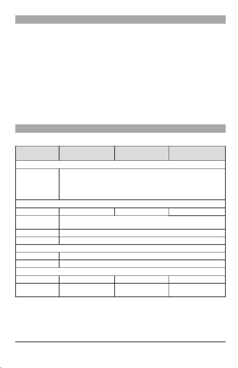
Ratings Compatibility
Table 1:Communicator Ratings
Model
3G2080(R)E/LE2080(R)
Cellularonly
Power Supply Ratings
Power is supplied from the panel’s PC-Link header or a PCL-422 module in
Input Voltage
remote cabinet installations. In remote cabinet installations, the PCL-422 module
located with the communicator is powered by either an HSM2204 or an HSM2300.
Refer to the PCL-422 installation instructions for details.
Current Consumption
Standby Current 90mA 100mA 120mA
Alarm (Transmitting)
Current
Operating Frequency 850MHz, 900MHz, 1800MHz, 1900MHz, 2100MHz
Typical Antenna Gain 2dBi
Environmental Specifications
Operating Temperature -10°C to 55°C (0°C to 49°C for UL/ULC)
Humidity 5% ~ 93% relative humidity, non-condensing
Mechanical Specifications
Board Dimensions (mm) 100 × 150 × 15 100 x 150 x 15 100 × 150 × 15
Weight (grams) with
bracket
310 300 320
TL280(R)E
Internet only
10.8-12.5 VDC
400mA
TL2803G(R)E/TL280LE(R)
Internet andCellular
5

Table 2:Compatible Receivers and Panels
Communicator Receiver/Panel Description
l Sur-Gard System I-IPReceiver, version 1.13+
l Sur-Gard System II Receiver, version 2.10+
3G2080(R)E
LE2080(R)
TL2803G(R)E
TL280LE(R)
TL280(R)E
Receiver
Panel
l Sur-Gard SG-DRL3-IP, version 2.30+ (for Sur-Gard System III Receiver)
l Sur-Gard SG-DRL4-IP version 1.20+ (for Sur-Gard System IVReceiver)
l Sur-Gard SG-DRL5-IP version 1.00+ (for Sur-Gard System 5 Receiver)
l HS2016
l HS2016-4
l HS2032
l HS2064
l HS2128
NOTE: Enter [*][8][Installer Code][900] atkeypad to view thepanel versionnumber.
Pre Installation Configuration
Encryption
The communicator uses128 Bit AES encryption.Encryption can only be enabled from the monitoring station receiver.Each
receiver (Ethernet 1 and 2,Cellular 1 and 2) can independently have encryption enabled or disabled. When encryption is
enabled, the central station will configure the device to encryptcommunications the next time the communicator module performsa communication to that receiver.
NOTE: Packetswill startbeing encrypted onlyafter thenext eventis sent to that receiver,or ifthe unit is restarted.
Beforeleavingthe installationsite, the communicator TL2803(R)E /TL280LE(R) Ethernet line shallbe connected via
an APPROVED (acceptable to the local authorities) Network Interface Device (NID). All wiring shall be performed
accordingto the local electricalcodes.
Communicator Installation Configuration
Thisalarm communicator shall be installed byservice persons only (service person isdefined as a person having the appropriate technical training and experience necessary to be aware of hazards to which thatperson maybe exposed to in performing a task and can also takemeasures to minimize the risksto that person or other persons). The Communicator shall
be installed and used within an environment that provides the pollution degree max2, overvoltages categoryII,in non-hazardous, indoor locations only.This manual shall be used with the installation manual ofthe panel which is connectedto the
communicator. All instructions specified withinthe panel manual mustbe observed.
All the local rules imposed by localelectrical codesshall be observed and respected during installation.
Installing the Ethernet Cable (TLXXXX Models Only)
A Category 5 (CAT 5) Ethernet cable must be run from a source with Internet connectivity to the communicator module,
inside the panel. The communicator end of the cable mustbe terminated with an RJ45 plug, which will connect to the communicator’sRJ45 jack after the communicator is installed. All requirements for installation of CAT5 Ethernet cable must be
observed forcorrect operation of the communicator, including, butnot limitedto, the following:
l Do NOT strip off cable sheathing more than required for proper termination.
l Do NOT kink/knot cable.
l Do NOT crush cable with cable ties.
l Do NOT untwist CAT5 pairs more than ½ in. (1.2cm).
l Do NOT splice cable.
l Do NOT bend cable at right angles or make any other sharp bends.
NOTE: CAT5 specification requires thatany cable bend musthave a minimum2 in. (5 cm)bend radius.Maximum length of
CAT 5 cable is 328 ft. (100 m).
6
Inserting and Removing the SIM Card
10
4
1
2
8
3
7
6
5
11
9
9
8
1.
Remove the front cover of the panel to access SIM holder.
2.
Remove power from the panel and disconnect the battery and telephone line.
3.
On the SIM card holder push gently to slide the cover downwards to OPEN. This will unlatch the SIM card holder on
the top edge of the communicator PCB. (See Figure3).
4.
Tilt the top of the SIM card holder downwards to access the SIM card.
NOTE: The SIM can be damaged by bending or scratching contacts.Use caution when handling SIMcards.
5.
Insert or remove the SIM card, noting the orientation of the notches on the SIM card and the SIM card holder.
6.
When inserting a SIM card, insert the card in the proper orientation and gently push the SIM card holder down and
slide the holder as indicated by the arrow on SIM holder, to LOCK.
7.
Reconnect the backup battery and telephone line, apply AC power to panel, and replace the panel cover.
Running the RS-232 Cable (R models only)
When installing the communicator for use with 3rd partyapplications an RS-232 cable must be connected between the 3rd
party device and the communicator module.
NOTE: Maximum cable length for RS-232 cable is8 ft.(2.4 m).
Please refer to the installation manual for the 3rd party device for wiring instructions.
Installing Communicator in Panel
Installing the Communicator with HS20XX Panels
NOTE: Before installing the communicator or inserting/removing SIM, ensure that systempower is off and telephone line is
disconnected.
1.
To assemble supplied mounting bracket,perform the following: (See Figure 1).
a.
Remove the 4 white plastic standoffs from the bag provided with the communicator kit.
b.
Insert the 4 standoffs through the back of the mounting bracket,into the holes at each corner. (The antenna
mounting tab should be facing away from you).
c.
Place the bracket on a flat, solid surface. Hold the communicator component side up and orient the 4 holes on the
communicator with the 4 standoffs protruding from the bracket. Push the communicator firmly and evenly onto the
standoffs until it is securely attached to the mounting bracket.
d.
Remove the panel front cover.
e.
Remove and discard the circular knockout located in the top-right section of the panel. (This hole will be used for
connection of the supplied radio antenna).
f.
Connect the supplied 5” (12.7 cm) antenna cable to the radio, by passing the connector through the hole on back
of the mounting bracket to the communicator board. Push the antenna connector firmly into the socket on the cellular radio. (See Figure 3).
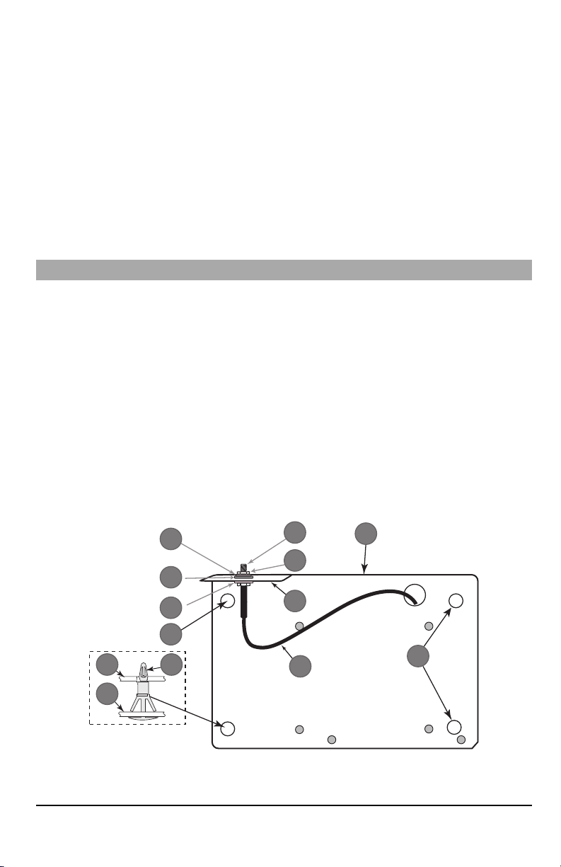
Figure 1: Communicator Mounting Bracket
7
Item Description
1
2
3
1 External Antenna Screw Thread
2 Brass Nut
3 Brass Washer
4 Nylon Washer (flat)
5 Antenna Mounting Tab
6 Nylon Washer with bushing (thicker flat washer)
7 Antenna Cable
8 Mounting Holes
9 Mounting Plate
10 Communicator Board
11 Stand Off
2.
Install the Communicator into the panel:
a.
Attach one end of the PC-LINK cable to the panel PCLINK_2 header on the panel (red wire goes on the righthand pin of the panelPCLINK_2 header (see Figure 3)).
b. Insert theassembled communicator intothe panel.
NOTE: Ensure thatthe threaded antenna connection point is visible through the knockout hole at the topright of
c. Placethe nylon washer with bushing (thick flat washer) onto the threaded section ofthe antenna cable.Insert the
d. Place the second nylon washer (flat), followed by the brasswasher and the brass nut,onto the threaded section
e.
f.
g. Using light pressure (finger tight only), attach the supplied white quad band whip antenna to the threaded
the panel.
threaded section through the antenna mounting knockout hole at top right ofpanel.
of the cable, outside the panel. Tighten the assembly by hand only (finger tight only- do not over tighten the
antenna assembly).
Locate the screw hole on the right side wall of the panel. See Figure 2 "screw". Line up the assembled com-
municator with the right side wall ofthe panel and, using the screwprovided, secure the mounting bracketto the
panel.
Attach the other end of the PC-LINK cable to thecommunicator (red wire goes on theright-hand pin ofthe com-
municatorPC-LINKheader (See Figure3)).
antenna connection point at top of the panel.
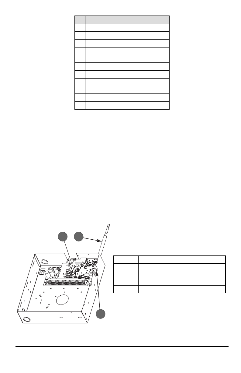
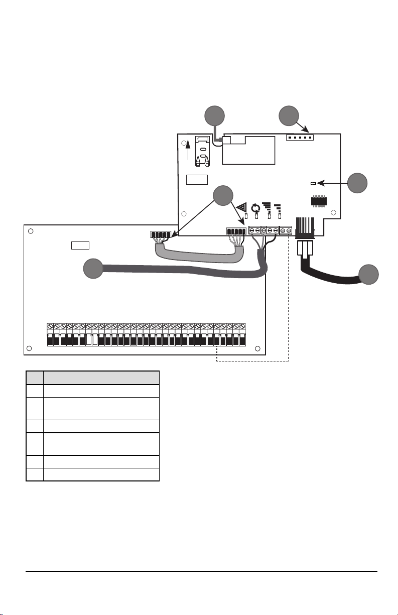
Figure 2: HS2016/2016-4/2032/2064/2128 Control Panel
Item Description
1 PC-Link Cable Connector
Quad Band Whip Antenna - Use light pressure to
2
WARNING! - 3G2080(R) E/TL2803G(R)E/LE2080(R)/TL280LE(R) modules are power limited. Do not route any wiring
over the circuit board. Maintainat least 1in. (25.4mm) separation between circuit board and wiring. A minimum of ¼
in.(7mm) separationmust bemaintainedat allpoints between non-powerlimitedwiring and power limited wiring.
8
attach antenna fingertight only
3 Screw
3.
AUDIO/DEFAULT
DSC
UA685
PC-LINK
PCLINK_2
COM
TL2803G(R)E
3G2080(R)E
TL280(R)E
TL280LE(R)
LE2080(R)
AC
AC
Z1 COM Z2 Z3 COM Z4 Z5 COM Z6 Z7 COM Z8
AUX+
BELL +
PGM1 PGM3
RING
T-1
HS2016/2032/2064/2128
3G/LTE Radio
UA621
L
o
c
k
1
RJ-45
GRN
YEL
TIP
R-1
BLK
RED
AUX -
BELL -
EGND
TX+
GND
TX-
RX+
RX-
SHLD
SIM
PGM2 PGM4
4
1 2
3
5
6
To electrically connect the communicator to the panel, perform the following steps (See Figure 3):
a.
Disconnect both ACpower and battery connections from the panel, and disconnect telephone line.
b.
Confirm that the SIMcard is inserted in the holder and locked.
4.
Install Network Cable (TLXXXXmodels only). Route the CAT 5 Ethernet cable through back of the panel and plug it
into the communicator’s RJ45 jack.
NOTE: Before leaving the premisesthe Ethernet communication lines must first be connected to an approved (acceptable
to local authorities) type NID.All wiring shall be performed according to the local electrical codes.
Figure 3: Communicator Wiring Diagram
Item Description
1 To External Antenna
AUDIO/ DEFAULT
2
Jumper pins 4 and 5 to reset
3 Network Link - Yellow
From NID use only CAT5 supervised
4
maximum cable length 100m (328 feet)
5 RS-232 to third party device
6 RED Wire
5.
Install the RS-232 connections (R models only). Ifusing the communicator with a 3rd party device, wire the con-
Input Ratings:
l +10.8V ~ +12.5VDC
l 90mA 3G2080(R)E/120mA TL2803G(R)E standby
l
l
l 100mA TL280(R)E
l 400mA alarm
DSC Panelminimumpower requirements:
l 16.5 VAC 40 VAtransformer
l 12 VDC 7Ah battery
90mA 3G2080(R)E/ LE2080(R)
120mA TL2803G(R)E/TL280LE(R)
nections as per the table below:
9
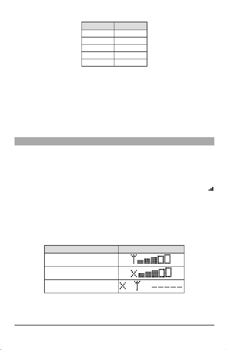
Table 3:RS-232 Connections
OR AND
3rdParty Device Communicator
TX (RED)* RX+
Unused RX-
RX (GRN)* TX+
Unused TX-
GND (BLK)* GND
* Wire colors based on the cable provided in the product box.
6.
Perform the following steps for initial power on of the panel with communicator installed:
a.
Reconnect the ACpower, telephone line, and battery + connector to the panel.
(The communicator and panel will power up together).
b.
Observe that the communicator’s red and yellow LEDs are flashing together while it initializes. The red and yellow
LEDs will continue to flash until the communicator has successfully communicated to all programmed receivers.
NOTE: During radio reset,the two green LEDs will flash alternately.
NOTE: Initialization may take several minutes to complete.Red and yellowLEDs will flash together during initialization. Do
not continue to next step until the red and yellow LEDs have stopped flashing. (If only the yellow LED is flashing,
there is a communicator trouble and the green LEDs are not valid for communicator placement test).
Correct trouble indicated by flashes on yellow LED before continuing. (See Table 7 for troubleshooting assistance).
7.
Perform the communicator placement testbelow.
8.
Mount the panel in final location indicated by placement test.
Communicator Placement Test
Cellular Communicator Models Only
To confirm thatthe cellular antenna location is suitable for radio operation,perform the placementtestas follows:
NOTE: It might be necessary to relocate the panel or install an optional extension antenna during this procedure, if the
radio signal strength is too low.
1.
Confirm that the yellow LED on the communicator is not flashing. Aflashing yellow LED indicates trouble on the communicator. See Table 7 to
2.
Confirm that the strength of the radio signal on the yellow LED and the 2 green LEDs on the communicator meet or
exceed the minimum signal level requirement. Minimum signal level: The yellow LED is OFF and the green LED 1
(furthest from the yellow LED) is ON (i.e., not flashing) for the panel location to be acceptable. For interpretation of
receiver strength on LEDs, refer to the table “Radio SignalStrength”.
Cellular Signal Strength Display - LCD Keypad only
The cellular network signal strength can be checked on the keypad LCDscreen by entering installer programming section
[850].The LCDwill indicatethe SIMcard activation status followed by up to fivebars of signal strength.This displaywill automatically update every three seconds. For the relationship between signal strength bars, CSQ level, and signal level in
dBm, refer to “RadioSignalStrength”.
troubleshoot and correct the cause of this trouble before continuing to the next step.
Table 4:Signal Strength Display
Description Display
SIM card active and current signal strength
SIM card inactive and current signal strength
Radio not registered
NOTE: If the required signal strength is too low with the panel in its current location, the panel must be relocated or an
external antenna is required.
Ifrequired, the following cellular extension antenna kits are available to the installer:
l GS-15ANTQ - 4.57m (15’) internal antenna extension kit (suitable for interior mounting).
l GS-25ANTQ - 7.62m (25’) external antenna extension kit (suitable for interior/exterior mounting).
10

l GS-50ANTQ - 15.24m(50’) external antenna extension kit (suitable for interior/exterior mounting).
Specificinstructions for the installation of the extension antenna are included with the kit. Observe all the electrical safety
instructions regarding the installation of the antenna. All the wiring of the equipment shall be fully compliant with the local
rules and regulations.
3.
If required, install the antenna extension and perform the following steps to determine the best location for placement
of the antenna:
a.
Disconnect the white whip antenna from the panel.
b.
Attach one end of the antenna extension cable to the threaded antenna connector on the panel and the other
end to the external antenna.
4.
Move the extension antenna to various locations while observing the two green LEDs on the panel.
a. Continue to reposition the extension antenna until it receives an acceptable (minimum one green LED ON solid)
signal strength.
NOTE: Minimum strength is: green LED 1 flashing and yellow LED off.If green LED 1 is flashing, relo-
cation should be considered.
b.
Mount the supplied antenna extension bracket at the location that provides the best signal strength.
5.
Alternately, reposition the panel to improve signal strength. Dismount the panel and move it to another location to
achieve the required signal strength. Ifthe panel is relocated to improve signal strength, mount itin the new location.
6.
When final panel/antenna location is determined, continue at the Initial PanelProgramming section.
NOTE: If theSIM card is notactivated, placementtestwill indicate the signal strength of the nearest cellular tower.
NOTE: In between displaying signal strength, the signal strength LEDs will flash alternatelyif an inactiveSIM card is used.
The flashing indicates that themodule is attempting to attach to the cellular networkand will only lastbriefly.
Initial Panel Programming
Keypad Data Display
l
Section-Toggle Options: The number is displayed when toggle is ONand the number is not displayed when toggle is
OFF.(e.g., toggle options displays: [--3--6--]. Options 3 and 6 are ON, all others are OFF). Pressing keys 1 through 8 will
alternately turn the toggle ON and OFF.
l
HEX/DecimalData: Values that are provided with two defaults, separated by a “/” character, use the format: hexa-
decimal followed by decimal equivalent (e.g., default [0BF5/3061]). Hexadecimal numbers are shown, with all leading
zeroes, to the full field length defined for the number.
Entering HEX values at keypad
To enter HEX values at the keypad,press the * key before entering the HEX value. (e.g.,to enter “C” at the keypad,press [*]
[3])
Entering ASCII Characters at keypad
1.
Press [*]and use scroll buttons [<] [>]to display “ASCIIEntry” on the LCD screen.
2.
Press [*]to select ASCII entry mode.
3.
Use the [<] [>] scroll keys to display the desired character and press [*]to save and exit ASCII.
4.
Repeat the steps above to enter another ASCII character.
HS2016/2016-4/2032/2064/2128 Initial Programming
For detailed information, refer to panel manual section ‘Alternate Communicator Set-up’. These sections must be programmed at the panel keypad. Enter [*][8][Installer Code][SectionNumber]. Record any values that are modified from
their default,in theappropriate worksheets for the panel or communicator.
1.
In panel section [377] ‘Communication Variables’, subsection [002] ‘Communication Delays’, sub-subsection [1]
‘Communication Delay’, program 060 (seconds).
2.
In panel section [382] ‘Communicator Option 3’ set option [5] ON.
NOTE: If thisoption isOFF, the yellow statusLED on the communicator will indicate ‘Panel Supervision Trouble’ (2 flashes)
and the unit can not be programmed via the PC-LINK cable.
Activating the Communicator with C24 Communications
Installation of the 3G2080(R)E /LE2080(R) or TL2803G(R)E / TL280LE(R) in North Americarequires activationwith C24
Communications in order to operate. Please contact the central station (C24 Communications Master Reseller) to confirm
the required stepsto activate / program the communicator.
All communicator options mustbe programmed via C24 Communications,except the following Ethernet options which can
also be programmed using the keypad or DLS:
l [001] Ethernet IPAddress
l [002] Ethernet IPSubnet Mask
l [003] Ethernet Gateway IPAddress
11
NOTE: The SIM activation with the carrier can take several hours to complete. It is recommended the activation be com-
pleted prior to arrival on the customer site to avoid possible installation delays.
Once theSIM activation is complete, the communicator willautomaticallyconnect and download itsprogramming from C24
Communications.
Communicator Status LEDs
The communicator has four on-board LED indicators. These include one yellow trouble LED, one red network connection
status LEDand two green signal strength LEDs.The LED meaning isdescribed in thissection.
Yellow Trouble LED
Thisyellow LED will flash to indicate a trouble on the unit.The number offlashes indicates the type of trouble. See the table
below for the coded flashes and the conditions whichwill activate the trouble status LED.
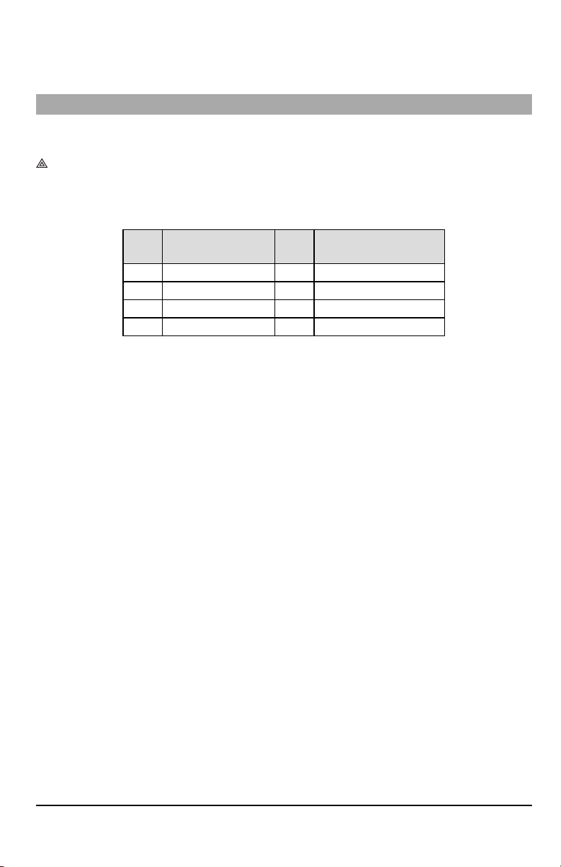
Table 5:Yellow Trouble StatusLED
# of
Flashes
2 Panel Supervision Trouble 7 Receiver Not Available Trouble
4 Not Applicable 8 Receiver Supervision Trouble
5 Cellular Trouble 9 FTC Trouble
6 Ethernet Trouble 12 Module Configuration Trouble
NOTE: Only the highestpriority trouble (2 flashes is the highestpriority trouble) is indicated. When this trouble is restored,
the nexthighesttrouble will indicate,if present.This will continue untilall troubles have been cleared (yellow LED is
not flashing).
The following paragraphs describe the conditions associated with each trouble:
Trouble
Panel Supervision Trouble (2 Flashes)
Thistrouble will be indicated when communication between the communicator module and the panel fails. If the module
can notcommunicatewith the panel (e.g.,loss ofpower to the panel) the communicator willsend the ‘Panel Absent Trouble
Event’ message to the central station receiver.When communication returns,a ‘Panel Absent Restore Event’ is sent by the
communicator to the central station receiver. The reporting codes are ET0001 for trouble and ER0001 for restore. The
panel absent eventalwaysuses the primary receiveraccount code when communicating to the central station.
NOTE: The panel supervision trouble/restore are internally generated eventsby the communicator. Trouble isgenerated if
the communicator misses 6 polls. Trouble isrestored on receipt of firstpoll fromthe panel.
Cellular Trouble (5 Flashes)
Thistrouble is indicated for any of the following 4 conditions:
1.
Radio Failure: Trouble is indicated after 8 failed attempts to communicate with the cellular radio.
2.
SIMFailure: Trouble is indicated after 10 failed attempts to communicate with the SIM.
3.
CellularNetwork Trouble: Trouble is indicated for loss of the registration to the network provider.
4.
Insufficient SignalStrength: Trouble is indicated if calculated average signal strength is too low. (Both green LEDs
are OFF). Trouble will clear when the calculated average signal strength is above minimum (i.e., > CSQ 5).
NOTE: If Option [851][005] Bit8 is Off, CSQ less than or equal to 4 will not trigger Cellular Trouble
Ethernet Trouble (6 Flashes)
Thistrouble is indicated when an Ethernet link between the transmitter and the local switchor router isabsent.This trouble
will alsobe indicated ifthe unit fails toget Dynamic Host Control Protocol (DHCP) settings from the DHCP server. (Not active
if Ethernet receiversare not programmed).
Receiver Not Available (7 Flashes)
Thistrouble is indicated if the unit is not able tosuccessfully initialize withany of the programmed receivers. Unprogrammed
receivers are excluded. This trouble is also indicated if the cellular receiver APNs have not been programmed in sections
[205] and [215].
Receiver Supervision Trouble (8 Flashes)
Thistrouble is indicated when receiver supervision is enabled and communication between the communicator module and
the receiver fails. Trouble is indicated if Ethernet 1 and/or cellular 1 issupervised and does not receive a heartbeat from the
# of
Flashes
Trouble
12

receiver or if cellular issupervised and the unit does not receive an acknowledgment to 4 heartbeats sentto the receiver.
FTC Trouble (9 Flashes)
Thistrouble is indicated when the unit fails to communicate module events to the central station.Trouble isdisplayed after
the unit has exhausted all communications attempts to all programmed receivers for events generated by the communicator.
Module Configuration Trouble (12 Flashes)
This trouble is indicated when the system account code or the receiver account have not been programmed. Disabled
receivers are excluded.
Red Network Connection Status LED
TL2803G(R)E / TL280LE(R)
BLINKING: Indicates communications in progress.
l Once quickly for outgoing Ethernet transmission.
l Twice quickly to indicate incoming Ethernet ACK/NACK.
OFF:This is the normal state ofthe red network connection status LED.There are no networkconnection issues present.
ON:There is a problem with the Ethernet or the cellular network connection. LED will be ON if any of the following occur:
Ethernet cable is not connected,DHCP configuration times out,unit fails to get an IP address from the cellular network, or
Cellular connection has been reset.
(Green LED 1) (Green LED 2) and (Yellow LED) Signal Strength
NOTE: If the yellow LED is flashing, signal strength in table below is not valid.
See Table 7 for troubleshooting flashing yellow LED.
13
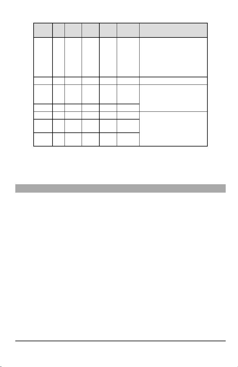
Table 6:Radio Signal Strength
Signal
CSQ
Yellow
Green
Strength
Level
LED
LED 2
Green
LED 1
Signal
Level dBm
ActionRequired
Ifthis statuspersistsand the yellow
LED shows5 flashes,confirm that the
Radio
Not
Ready
N/A N/A
Alternate
Flashing
Alternate
Flashing
SIMcard is active.
Confirmcellular service is active in
N/A
area.
Relocatepanel or install external
antenna.
No Signal 0 ON OFF OFF -113 or less Check all antenna connections.
1 Bar 1 - 4
2 Bars 5 - 6 OFF OFF Flashing -103 ~ -101
3 Bars 7 - 10 OFF OFF ON -99 ~ -93
4 Bars
5 Bars 14 + OFF ON ON
Flashing
See
OFF Flashing -111 ~ -105
Note
11-
OFF Flashing ON -91 ~ -87
13
-85 and
Relocate panel or install external
antenna if yellow trouble LED shows
five flashes.
Location is OK.Cellular signal strength
is greater than CSQ7.
higher
NOTE: The communicatorwill indicate cellular trouble (yellow LED = 5 flashes) ifthe calculated average CSQ Level is 4 or
less.
Network Activity LEDs - Red and Green (TL2803G(R)E/TL280LE(R) only)
l
Ethernet Activity: Red LED will blink quickly once for transmit, or twice for receive.
l
CellularActivity:Green LED 2 will blink quickly once for transmit, or twice for receive
Communicator Reset/Update
Factory Defaults Reset
Restore the programming options for the communicator to the factorysettings by installing a hardware jumper. Perform the
following steps to reset the communicator:
NOTE: A jumper is required on AUDIO/DEFAULTpins 4 and 5 to resetthe hardware values.
1.
Remove panel front cover.
2.
Locate the AUDIO/DEFAULT 5 pin connector on the communicator board (see Figure 3).
3.
Apply a jumper to short the hardware default pins 4 and 5.
4.
Remove AC and DC power from the panel and then reapply power to the panel.
5.
Wait until the two green LEDs on the communicator begin flashing rapidly.
6.
Remove the jumper from the hardware default pins 4 and 5 (green LEDs will stop flashing).
7.
Replace the panel cover.
NOTE: The communicatorhas now been resetto the factorydefault values.
Firmware Update
The firmware ofthe device can be updated over cellular or Ethernet (remote or local updating):
l When the firmware update begins, all 4 LEDs are ON.
l During the firmware update process, the LEDs will cycle in a chaser pattern.
l During the firmware update process, the chaser pattern will briefly pause and resume again. This indicates firmware
verification check has passed, and application update will begin.
l After a successful update, the unit will automatically restart.
l Should the update fail, all 4 LEDs will flash ON,then OFF together at 1 second intervals.
NOTE: If the firmware update fails, restart the communicator by cycling power. For persistent update failures, contact tech-
nical supportfor assistance.
14
 Loading...