

Page 1

TL280(R)
Internet Alarm Communicator - International
Installation Manual V4.1
Warning: This manual contains informationon limitations regarding product use and function and inform-
ationon the limitationsas tothe liability of themanufacturer. Theentire manualshouldbe carefullyread.
Page 2

Table of Contents
Table of Contents 2
WARNING: Installerplease read carefully 3
General 4
Model Information 4
Panel Mounting 4
Features 4
EN50131-1 InstallationRequirements 4
Technical Specifications, Ratings and Compatibility 5
Pre Installation Configuration 5
Communicator InstallationConfiguration 6
Installing Communicator in Panel 6
InitialPanel Programming 8
Communicator Status LEDs 9
Communicator Troubleshooting 10
Ethernet Programming Options 11
Ethernet Cellular Programming Worksheets 22
Warranty 25
EULA 25
Regulatory Information 26
2
Page 3

WARNING: Installer please read
carefully
Note to Installers
The warningson th ispa geco ntainvital information. Asth eon lyindividual in contact with systemusers, itisth einstaller’sresponsibilityto bring each item in this
warning to the atte ntion ofa llusers ofthissystem.
System Failures
Thissystemh asbe en carefullyde signed to be ase ffectiveaspo ssible.Th erea re
circumstances, however, involving fire, burglary, orot hert ypes ofemergencies
whe re it mayn otp rovide protection. Anya larmsystemo fan ytype maybe compromised deliberat elyo rmayfa ilto ope rate asexpe cted for avariety of reasons.
Some, but not all,o fth erea sons maybe:
Acc ess by Intruders
Intrud ersmayente rthrou gh anu nprotecte daccesspoint, circumvent asensing
device, evade detection bymoving through an area of insufficient coverage ,disconne ct awarning device, orinterfe re withor prevent the proper opera tion of the
system.
Component Failure
Although every effort has been made to make thissystemas reliable asp ossible,
the systemmayf ailto function asinte nded due to the failure ofa compone nt.
Comprom ise of Radio Frequency (Wirele ss) Device s
Signalsmay not reach the receiveru nder allcircumstancesw hich could include
metal objectsplaced on or near the radio path ord eliberate jamming oro therinadvertent radio signa linterferen ce.
Criminal Knowledge
Thissystemcontains securityf eatures whichw erekno wnto be effectiveat the
timeo fmanufacture. It ispossiblef orpe rsons withcriminal intent to develop technique swhich redu ce the effectiveness oft hese features. It isimportan tthat the
securitysystemb ereviewed periodicallyto ensu re that itsfea turesremain effectivea ndt hat itisupd ated orre placedif itisf ound that itd oesn otp rovide the protection expected .
Failure of R eplaceable Batter ies
Thissystem’swirelesstran smitters have been designe dto provide severalyea rs
of batte rylife unde rnormalconditions. The expected batterylife isa function of
the device environment, usage, and type. Ambient conditions sucha shigh humidity,h igh orlow tempera tures,o rlarge temperatu refluctua tions mayredu ce the
expecte dbattery life. While each transmitting device hasa low batte rymonitor
which iden tifieswh en the batteries need to be replaced, thismonitor mayfailto
ope rate as expected. Reg ular testing and mainten ance willkeep the systemin
goo do perating condition.
Inadequate Installation
Asecurity systemmust be installed properlyin order to provide adeq uate protection. Everyinstallation should be evaluated by asecurityprofessionalto
ensure tha talla ccesspo ints and areas arecovered. Locksand latcheson window sand doo rsmustb esecure and op erate asinten ded. Windows, doors,
walls,ceilingsa nd other building materialsmust beof sufficient strength and construction toprovide the level ofp rotection expected. Areevaluation mustbe do ne
during and afte ran yconstruction activity.An evaluation by the fire and/o rpolice
dep artment ishigh lyrecommende dif thisserviceisa vailable.
Inadequate Testing
Mostp roblemsthat wou ld prevent an alarmsystemfrom operating as inten ded
can be found by regular testing and maintenance. The complete systemsho uld
be tested wee klyan dimmediate lyaf tera brea k-in,a nattempted break-in,a fire,
a storm,an earthqua ke, an accident, oran ykind ofcon struction activityinside or
outside the premises.Th ete sting should include allsensing devices,keypa ds,
consoles, alarmindicating devices,an da nyoth erop erational devicestha tare
part of the system.
Insufficie nt Time
There mayb ecircumstances when the systemwillop erate asinte nded, yet the
occupan tswillnot be prote cted froman emergency due to theirinab ilityt o
respon dto the warn ings in atimelymann er.If the systemisremotelymonitored,
the respon se mayn ot occur in timeto pro tectth eo ccupantso rtheirbelon gings.
Motion Dete ctor s
Motion detecto rscan onlydet ectmotion within the designated are asas shown in
their respectiveinstallation instructions.Th eycann otd iscriminate betw een
intrude rsa ndintende do ccupan ts. Motion dete ctorsdo not provide volumetric
area prote ction. They have multiplebeamso fde tection and motion can onlybe
dete cted in unobstructed areascovered bythese beams. Theycannot detect
motion whicho ccursbe hind walls,ceilings, floor, closed doors,glass partitions,
glassd oorsor window s. Anytype of tampering whethe rintent ional orunintent ional sucha smasking, painting, or spraying of anymat erialo nth elenses,mirrors,windowsor any other part of the detection system willimpairitsp rope r
ope ration.
Passive infrared motion detecto rso perate bysen sing change sintemperatu re.
However theiref fectiveness canb ereduced whe nth ea mbient temperatu re
rises near orab oveb odytemperatu re orif there are intentionalor uninten tiona l
sources ofh eat in orne arth ed etection area. Some of these heat sourcescould
be hea ters,radiat ors, stoves, barbecues, fireplaces, sunlight, steam vents,lighting and soo n.
Power Failure
Con trolunits, intrusion dete ctors, smoke detectors and many other security
devicesre quirean ad equate po wersup plyfor proper opera tion. If ad eviceo perates fromb atteries,it ispossible forth ebatteries to fail.Even ift heb atterieshave
not failed, they must be charge d,in goo dcondition and installed correctly.If a
device operate sonlyb yAC power, any interrup tion, howe ver brief, willrende r
that de vice inop erativewh ileit does not have power. Power interruptions of any
length are ofte na ccompanied byvoltage fluctuationswh ichmay damage electronic equipment sucha sa securitysystem.After a power interruption has
occurred, immediatelycon duct acomplete systemtest to ensure that the system
ope rates asintende d.
Security and Insurance
Reg ardlessof itscapa bilities,an alarmsystemisn ota substitute forp rope rtyo rlife
insurance. Analarmsystema lsois not asub stitute for property owners, renters, or
othe roccupa ntsto act pruden tlyto prevent or minimize the harmfulef fectsof an
emergen cysituat ion.
Smoke D ete ctor s
Smoked etectorst hat area pa rt oft hissystemmay not prope rlyalert occupant sof
a fire fora nu mber of reason s, some ofw hich follow. The smoke detecto rsmay
have bee nimproperly installed orpo sitione d.Smoke may not be ablet orea ch the
smoked etectors, such aswh en the fire isin ach imney,w allsor roofs, oron the
othe rside ofclosed doo rs.Smoke detecto rsmay not detect smoke fromfires on
ano ther levelof the residence or building.
Everyfire isdiffe rent in the amoun tof smokep roduced and the rate of burning.
Smoked etectorscan not sense alltype sof fireseq uallywe ll.Smoke detectors may
not provide timelywa rning of fires caused by carelessness orsafe tyhazardssuch
as smoking inb ed, violent explosions, escaping gas, improper storage of flammable materials,o verloade de lectricalcircuits,children playing with matches, or
arson.
Even ift hesmoke detecto rope ratesa sintend ed, there may be circumstances
whe nth ereis insufficient warning to allow alloccupan tsto escape intime to avoid
injuryor death.
Telephone Lines
If telepho nelines are used tot ransmitalarms,t heymay be out ofse rvice orbu sy
for certainp eriods of time. Also an intrude rmaycut the telephon eline ord efeat its
ope ration by more soph isticated means whichmaybe difficultt odetect.
Warning De vices
Warning devicessuch assirens, bells, horns, orstrobesmayno twa rn peopleo r
waken someone sleeping ift here isan interven ing wallor door. If warning devices
are located on a differen tlevel ofthe residence orp remise, then itis lesslikelythat
the occupants willbe alerted or awakene d.Aud ible warning devicesmayb e
interfere dwith by other noisesou rces such asstereo s, radios,te levisions, airconditioners, other appliances, or passing traffic.Aud ible warning devices, however
loud, maynot be heard bya he aring-impaired person.
3
Page 4

General
IMPORTANT
This installation manual shall be used in conjunction with the control panel. All safety instructions specified within that manual
shall be observed. The control panel is referenced as the “panel” throughout this document. This installation guide provides
the basicwiring, programming and troubleshooting information.Use this guide in conjunction with the Installation Manual available online from the DSCwebsite at www.dsc.com.
The Ethernet communicator is a fixed, wall-mounted unit, and shall be installed in the location specified in these instructions.The equipment enclosure must be fully assembled and closed, with all the necessary screws/tabs, and secured to a wall
before operation. Internal wiring must be routed in a manner that prevents:
l Excessive strain on wire and on terminal connections,
l Interference between power limited and non power limited wiring,
l Loosening of terminal connections,or
l Damage ofconductor insulation.
WARNING: Never installthis equipment duringa lightning storm!
Safety Information
The installer mustinstruct the systemuser on each of the following:
l Do notattemptto service this product. Opening or removing coversmay expose the user to dangerous voltagesor other
risks.
l Any servicing shall be referred to service personsonly.
l Use authorized accessories only with this equipment.
l Do notstayclose to the equipment during device operation.
Model Information
This manual covers the following model of alarm communicator: TL280 and TL280R.References to model TL280(R) throughout this manual applies to all specified models unless stated differently.Models ending in “R” include a built-in RS-232 interface for connecting to local third partyapplications.
The TL280 (R) is an Ethernet alarm communicator that sends alarm communication to Sur-Gard System I- IP, II, III (SGDRL3IP),IV (SG-DRL4IP), and 5 (SG-DRL5IP) central station receiversthrough Ethernet/Internet.
The TL280(R) supports integration over IP and is available with licensed 3rd partyproduct solutions.Specific programming for
the related programming sections is to be provided by the 3rd party. A current list of compatible 3rd party solutions can be
found at www.dsc.com.
The communicator can be used aseither a backup or primarycommunicator. The communicator supports Internet Protocol (IP)
transmission ofpanel and communicator eventsover Internet.
Panel Mounting
The TL280 communicator is compatible with HS2016, HS2032, HS2064, and HS2128 panels.
Features
l 128-bit AES encryption via Ethernet/Internet(NISTvalidation certificatenumber 2645).
l Ethernet LAN/WAN 10/100 BASE-T.
l Individual Internet periodic testtransmission.
l Integrated call routing.
l Visual Verification (requires Sur-Gard System 5 Receiver)
l Remote firmware upgrade capability of the communicator and panel firmware viaInternet.
l Panel remote uploading/downloading support via Internet.
l PC-LINK connection.
l SIA and ContactID (CID) formatssupported.
l Trouble display LEDs.
l Supervision heartbeats sent via Internet.
l Third partyintegration over cellular/IP. The product supports third partyapplication via serial (R-models only) and Eth-
ernet. Refer to third-partyapplication documentation for more information.
EN50131-1 Installation Requirements
For EN50131-1 compliant installations,the following programming options shall be setas described.
Supervision Heartbeat (required for ATS4 and ATS5):
4
Page 5

l
[851][004] setto 0087h (135s heartbeat).
NOTE: The compatible receiver at ARC location shall have supervision window programmed for 1800s (ATS4) or 180s (ATS
5).
l
[851][005] options 1 and 3 shall be enabled
Testtransmission (required for ATS3):
l
[851] System testoptions [026] and [027] shall be enabled (FF)for the communication pathsavailable.
l
[851][124] and [125] shall be programmed with time ofday for test transmission and 1440 minutes(24h) for testtransmission cycle
Configuration ofcommunication paths (all ATS classes)
l
[300][001] selectoption 02 for auto routing (this will allow transmission ofthe eventsover all available communication
paths in the system)
l
[380] enable option 5 (YES) for parallel transmission over all available communication paths (ifredundant configuration is
desired)
l
[382] enable option 5 (YES) this will enable Alternate communicator
l
[384] enable the desired back-up configuration (receiver 2back-up for receiver 1 or receiver 3 back-up for receiver 1).
Technical Specifications, Ratings and Compatibility
Table 1: Communicator Ratings
Model TL280(R)
Power Supply Ratings
10.8-12.5 VDC.
Power is supplied from the panel’s PC- Link header or a PCL- 422
Input Voltage
Current Consumption
Current 100mA @ 13.66V
EnvironmentalSpecifications
Operating Temperature -10°C to 55°C
Humidity 5% ~ 93% relativehumidity,non-condensing
Mechanical Specifications
Board Dimensions (mm) 100 × 150 ×15
Weight (grams)with bracket 290
module in remote cabinet installations. In remote cabinet installations, the
PCL-422 module located with the communicator ispowered by either an
HSM2204 or an HSM2300. Refer to the PCL-422 installation instructions
for details.
Table 2: Compatible Receivers and Panels
Communicator Receiver/Panel Description
l Sur-Gard SystemI-IP Receiver,version 1.13+
l Sur-Gard SystemIIReceiver,version 2.10+
3G2080(R) Receiver
TL2803G(R) Panel
l Sur-Gard SG-DRL3-IP,version 2.30+ (for Sur-Gard System IIIReceiver)
l Sur-Gard SG-DRL4-IP version 1.20+ (for Sur-Gard SystemIV Receiver)
l Sur-Gard SG-DRL5-IP version 1.00+ (for Sur-Gard System5 Receiver)
l HS2016
l HS2032
l HS2064
l HS2128
NOTE: Enter [*][8][Installer Code][900] atkeypad to viewthe panel version number.
Pre Installation Configuration
Encryption
The communicator uses 128 Bit AES encryption. Encryption can only be enabled from the monitoring station receiver. Each
receiver (Ethernet 1 and 2) can independentlyhave encryption enabled or disabled. When encryption is enabled, the central
station will configure the device to encrypt communicationsthe next time the communicator module performs a communication
to that receiver.
NOTE: Packets will start being encrypted only after the nextevent issent to that receiver, or ifthe unit is restarted.
5
Page 6

Communicator Installation Configuration
Mounting
Holes
Mounting Holes
Mounting Plate
Communicator
Board
Mounting
Plate
Stand Off
This Ethernet communicator shall be installed byservice persons only(service person is defined asa person having the appropriate technical training and experience necessary to be aware of hazards to which that person may be exposed to in performing a task and can also take measures to minimize the risks to that person or other persons). The Communicator shall be
installed and used within an environmentthat providesthe pollution degree max2, overvoltages category II,in non-hazardous,
indoor locations only. This manual shall be used with the installation manual of the panel which is connected to the communicator.All instructions specified within the panel manual must be observed.
All the local rules imposed by local electrical codesshall be observed and respected during installation.
Installing the Ethernet Cable
A Category5 (CAT 5) Ethernet cable must be run from a source with Internet connectivity to the communicator module, inside
the panel. The communicator end of the cable mustbe terminated with an RJ45 plug, which will connectto the communicator’s
RJ45 jack after the communicator isinstalled. All requirementsfor installation ofCAT5 Ethernet cable mustbe observed for correct operation ofthe communicator, including, but not limited to,the following:
l Do NOT strip offcable sheathing more than required for proper termination.
l Do NOT kink/knot cable.
l Do NOT crush cable with cable ties.
l Do NOT untwistCAT5 pairsmore than ½in. (1.2cm).
l Do NOT splice cable.
l Do NOT bend cable atright angles or make anyother sharp bends.
NOTE: CAT5 specification requires that any cable bend must have a minimum 2 in. (5 cm) bend radius. Maximum length of
CAT 5 cable is 328 ft.(100 m).
Running the RS-232 Cable (R models only)
When installing the communicator for use with 3rd party applications an RS-232 cable must be connected between the 3rd
party device and the communicator module.
NOTE: Maximum cable length for RS-232 cable is 8 ft.(2.4 m).
Please refer to the installation manual for the 3rd party device for wiring instructions.
Installing Communicator in Panel
Installing Communicator with HS2016, HS2032, HS2064, and HS2128 Panel
1.
To assemble supplied mounting bracket,perform the following: (See Figure 1).
a. Remove the 4 white plasticstandoffs from the bag provided with the communicator kit.
b. Insert the 4 standoffsthrough the back of the mounting bracket,into the holes at eachcorner.
c. Placethe bracketon a flat,solid surface. Hold the communicator component side up and orient the 4 holes on the
communicator with the 4 standoffsprotruding from the bracket.Push the communicator firmlyand evenly ontothe
standoffs until it is securely attached to the mounting bracket.
d. Remove the panel front cover.
e. Remove and discard the circular knockout located in the top-right section of the panel.
2. Install the Communicator into the panel:
a. Attach one end ofthe PC-LINK cable to the panel PCLINK_2 header on the panel (red wire goeson the right-hand
pin of the panel PCLINK_2 header (see Figure 3)).
b. Insert the assembled communicator intothe panel.
Figure 1: Communicator Mounting Bracket
6
Page 7
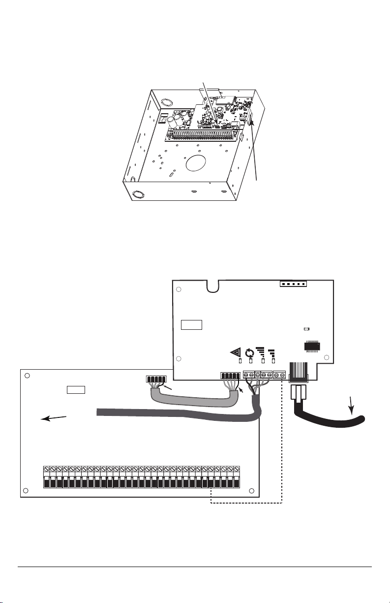
c.
PC-Link cable connector
screw
GSM Radio
RJ-45
UA601
HS2016/2032/2064/2128
AUDIO/DEFAULT
DSC
UA601
PC-LINK
COM
TL280(R)
AC
AC
Z1 COM Z2 Z3 COM Z4 Z5 COM Z6 Z7 COM Z8
AUX+
BELL +
PGM1 PGM3
RING
T-1
HS2016/2032/2064/2128
UA621
Input Ratings:
+10.8V ~ +12.5 VDC
100mA
DSC Panel min. power requirements:
- 16.5 VAC 40 VA transformer;
- 12 VDC 7Ah battery
Jumper pins 4 and 5
to reset.
1
From NID
Use only CAT5
Supervised
RJ-45
GRN
YEL
TIP
R-1
BLK
RED
AUX -
BELL -
EGND
TX+
GND
TX-
RX+
RX-
SHLD
Network Link
YELLOW
PGM2 PGM4
Maximum cable length
100 m (328 ft)
PCLINK_2
Red
Red
RS-232
To 3rd party device
Locate the screw hole on the right side wall ofthe panel. See Figure 2 "screw".Line up the assembled com-
municator with the right side wall ofthe panel and, using the screw provided, secure the mounting bracket to the
panel.
d.
Attach the other end of the PC-LINK cable to the communicator (red wire goes on the right-hand pin of the com-
municatorPC-LINK header (See Figure 3)).
Figure 2: HS2016/2032/2064/2128 Control Panel
WARNING! - Modules are power limited. Do not route any wiring over the circuit board. Maintain at least 1in. (25.4mm)
separation between circuit board and wiring. A minimum of ¼ in. (7mm) separation must be maintained at all points
between non-power limited wiring and power limited wiring.
3.
To electrically connect the communicator to the panel, performthe following steps(See Figure 3).
a. Disconnect both AC power and battery connections from the panel, and disconnect telephone line.
Figure 3: Communicator Wiring Diagram
4. Install the RS-232 connections (Rmodels only).Ifusing the communicator with a 3rd party device, wire the connections
as per the table below.Maximum cable length for RS-232 cable is 8 ft.(2.4 m).
NOTE: Please refer to the installation manual for the 3rd party device for wiring instructions.
7
Page 8

Table 3: RS-232 Connections
3rd Party Device Communicator
TX RX+
Unused RXRX TX+
Unused TXGND GND
Install Network Cable
1. Route the CAT5 Ethernet cable through backof the panel and plug it into the communicator’s RJ45 jack.
2. Perform the following stepsfor initial power on of the panel with communicator installed:
a. Reconnectthe AC power, telephone line, and battery+ connector to the panel.
(The communicator and panel will power up together).
b. Observe that the communicator’s red and yellow LEDsare flashing together while itinitializes.The red and yellow
LEDs will continue to flash until the communicator has successfully communicated to all programmed receivers. If this
is the first time the communicator hasbeen powered up, the module will not be able to initiate communication untilit
has been programmed.
NOTE: Initialization maytake several minutes to complete. Red and yellow LEDswill flash together during initialization. Do not
continue to nextstep until the red and yellow LEDs have stopped flashing. (If onlythe yellowLED is flashing, there is a
communicator trouble). Correct trouble indicated by flashes on yellow LED before continuing. (for troubleshooting
assistance see Table 6 ).
3. Mount the panel in location.
Initial Panel Programming
Keypad Data Display
NOTE: Programming locationsare accessible via the keypad.
l
Section-Toggle Options: The number is displayed when toggle is ON,the number is notdisplayed when toggle is OFF.
(e.g.,toggle options displays:[--3--6--]. Options3 and 6 are ON,all othersare OFF).Pressing keys 1through 8 will alternately turn the toggle ON and OFF.
l
HEX/DecimalData: Values that are provided with two defaults,separated bya “/” character,use the format:hexadecimal
followed bydecimal equivalent (e.g.,default [0BF5/3061]). Hexadecimal numbersare shown, with all leading zeros,to the
full field length defined for the number.
Entering HEX values at keypad
To enter HEX values atthe keypad, press the * key before entering the HEX value. (e.g., to enter “C” at the keypad, press[*][3])
Entering ASCII Characters at keypad
1. Press [*]and use scroll buttons [<][>]to display “ASCIIEntry”on the LCDscreen.
2. Press [*]to selectASCIIentry mode.
3. Use the [<] [>]scroll keysto displaythe desired character and press[*] to save and exitASCII.
4. Repeat the steps above to enter another ASCIIcharacter.
HS2016/2032/2064/2128 Initial Programming
Please refer to the panel manual for details. Perform the following steps to ensure that the communicator and the panel work
together as intended. These sections must be programmed at the panel keypad. Enter [*][8][Installer Code][Section Number].
Record anyvalues that are modified fromtheir default,in the appropriate worksheetsfor the panel or communicator.
1.
In panel section [377] ‘Communication Variables’, subsection [002] ‘Communication Delays’, sub-subsection [1] ‘Communication Delay’, program 060 (seconds).
2.
In panel section [382] ‘Communicator Option 3’ set option [5] ON.
NOTE: If this option isOFF, the yellow status LED on the communicator will indicate‘Panel Supervision Trouble’ (2 flashes)
and the unitcan not be programmed via the PC-LINK cable.
NOTE: Account number in communicator section [851][021] automatically syncs with panel system account number in section
[310][000] ‘Account Code’.
3.
In panel sections[300] subsections [001] to [004], program the subsection with 02 to 06.
8
Page 9
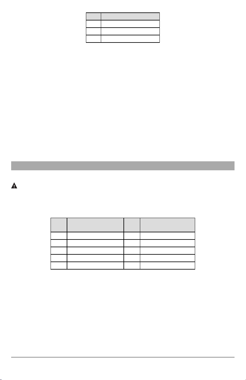
Table 4: Communicator Path Programming
Value CommunicationMethod
02 Auto Routing
03 Ethernet 1
04 Ethernet 2
NOTE: Refer to panel manual for additional information
4.
In panel section [350] ‘Communication Formats’,program the communication formatas:CID(03) or SIA FSK (04).
5.
In panel sections[311] - [318] ‘Partition Call Directions’,program the call direction options for the system.
6.
In panel section [401] ‘DLS/SA Options’,set toggle option [2]‘User Enable DLS’ to ONin order to performpanel DLS ses-
sion through cellular or Ethernet.
NOTE: Before leaving the premises, the installer should verify all programmed communications paths. See programming
options section [851][901]to send immediate testtransmissions.
Communicator Troubles displayed on a HS2016/2032/2064/2128
The communication trouble is the only trouble thatwill appear on the keypad Liquid Crystal Display (LCD) when encountered
by a communicator installed in a HS2016/2032/2064/2128. For more information about the trouble on the communicator module refer to the panel eventbuffer or by accessing *2 to viewthe individual trouble types.Log entrywill showFault or Restore for
each ofthe following events:
l Alt comm SIM lockTrouble/Restore
l Alt. comm Cellular Trouble/Restore
l Alt. comm Ethernet Trouble/Restore
l Alt. comm Fault/Restore
l Alt comm Receiver (1-4) Absent/Restore
l Alt comm Receiver (1-4) Supervision Trouble/Restore
l Alt comm Receiver (1-4) FTC Trouble/Restore
NOTE: When Panel displays“Alternate Fault”, communicator programming is not accessible via the keypad.
Communicator Status LEDs
The communicator has 2 on-board LED indicators:a yellow trouble LED and ared network connection statusLED.
Yellow Trouble LED
This yellow LED will flash to indicate a trouble on the unit. The number of flashes indicates the type of trouble. See the table
below for the coded flashes and the conditionswhich will activate the trouble statusLED.
Table 5: Yellow Trouble StatusLED
# of
Flashes
Trouble
# of
Flashes
Trouble
2 Panel Supervision Trouble 8 Receiver Supervision Trouble
4 Not Applicable 9 FTCTrouble
5 Not Applicable 10 Not Applicable
6 Ethernet Trouble 12 Module Configuration Trouble
7 Receiver Not Available Trouble
NOTE: Only the highestpriority trouble (2 flashes is the highest priority trouble) is indicated. When this trouble isrestored, the
next highest trouble will indicate, if present. This will continue until all troubles have been cleared (yellow LED is not
flashing).
The following paragraphs describe the conditions associated with the trouble indicated:
Panel Supervision Trouble (2 Flashes)
This trouble will be indicated when communication between the communicator module and the panel fails. Ifthe module can
not communicatewith the panel (e.g., loss of power to the panel) the communicator will send the ‘Panel Absent Trouble Event’
message to the central station receiver. When communication returns, a ‘Panel Absent Restore Event’ is sent by the communicator to the central station receiver. The reporting codes are ET0001 for trouble and ER0001 for restore. The panel
absent event always uses the primary receiver account code when communicating to the central station.
NOTE: The panel supervision trouble/restore are internally generated events bythe communicator. Trouble is generated if the
communicator misses6 polls. Trouble is restored on receipt of first poll from the panel.
9
Page 10

Ethernet Trouble (6 Flashes)
This trouble is indicated when Ethernet link between the transmitter and the local switch or router is absent. This trouble will
also be indicated if the unit fails to get DynamicHostControl Protocol (DHCP) settings from the DHCP server. (Not activeif Ethernet receiversare not programmed).
Receiver Not Available (7 Flashes)
This trouble is indicated if the unit is not able to successfully initialize with any ofthe programmed receivers. Unprogrammed
receivers are excluded.
Receiver Supervision Trouble (8 Flashes)
This trouble is indicated when receiver supervision is enabled and communication between the communicator module and the
receiver fails. Trouble is indicated if Ethernet 1 is supervised and does not receive aheartbeat fromthe receiver.
FTC Trouble (9 Flashes)
This trouble is indicated when the unit fails to communicate module eventsto the central station. Trouble is displayed after the
unit has exhausted all communications attemptsto all programmed receivers for eventsgenerated by the communicator.
Module Configuration Trouble (12 Flashes)
This trouble is indicated when the system accountcode or the receiver account have not been programmed.Disabled receivers are excluded.
Red Network Connection Status LED
BLINKING:Indicatescommunications in progress.
l Once quicklyfor outgoing Ethernet transmission.
l Twice quicklyto indicate incoming EthernetACK/NACK.
OFF:This is the normal state of the red networkconnection status LED.There are no network connection issues present.
ON: There is a problem with the Ethernet or the cellular network connection. LED will be ONif anyof the following occur:
l Ethernet cable isnot connected
l DHCP configuration timesout.
Network Activity LED (Red)
l
Ethernet Activity: Red LED willblink quicklyonce for transmit,or twice for receive.
Communicator Troubleshooting
NOTE: For additional details:
l Refer to section [983] for troubleshooting the firmware updates
l Refer to section [984] to verify the trouble status
Table 6: Trouble Indications
Trouble
Indication
No Indication N/A No Power
Yellow LED –
2 Flashes
Yellow LED –
6 Flashes
Trouble
Indicator
Digit
02
06
Possible
Causes
Panel
Supervision
Trouble
Ethernet
Trouble
l Checkthe power connections between the panel and the communicator.
l Confirm PC-LINK cable is properly installed between communicator and
panel.
l Checksection [382] toggle option[5] is ON (Alternate Communicator
Enabled).
l Ensure the PC-LINK cable between the panel and communicator is
connected properly (notreversed) and issecurely in place.
l Checkwith the ISP to confirm Internet service is active in the area.
l Ensure the Ethernet cable issecurely inserted into the RJ45 jackof the
communicator and the hub/router/switch.
l Checkthe link light on the hub/router/switch isON.Iflink light isOFF,start the
hub/router/switch.
l IfDHCP is used, ensure that the unit has an assigned IP addressfrom the
server.In Section [851][992] verifya valid IP address isprogrammed. If not,
contactthe network administrator.
l Ifproblem persists, replace the Ethernet cable and RJ45 connector.
10
Trouble Possible Solution
Page 11

Trouble
Indication
Yellow LED –
7 Flashes
Yellow LED –
8 Flashes
Yellow LED -
9 Flashes
Yellow LED –
12 Flashes
Red and Yellow
LEDs flashing
together
Trouble
Indicator
Digit
07
Possible
Causes
Receiver Not
Available
Receiver
08
Supervision
Trouble
09 FTC Trouble
Module
0C
Configuration
Trouble
Initialization
Sequence
N/A
Boot Loader
Failed
Trouble Possible Solution
l Ensure thatthe Ethernet path has Internet connectivity.
l Ifusing a staticIP address, confirm that the gatewayand subnet maskare
entered correctly.
l Ifthe network hasa firewall,ensure the network hasthe programmed
l outgoing ports open (defaultUDP port 3060 and port 3065).
l Ensure thatall the receivers are programmed for DHCP or have the proper IP
address and port number.
l This trouble is indicated when supervision isenabled and the unit isnot able
to successfully communicate with the receiver.
l Ifthis trouble persists, contactthe central station.
l The unit has exhausted all communications attempts to all programmed
receivers for eventsgenerated by the communicator.
l Restart the system, if trouble persists, contactthe dealer.
l This indication appears when section [021] system account code or sections
[101] or [111] receiver accountcode have notbeen programmed. Ensure that
a valid account code has been entered in these sections.
l The unit is still initializing please wait while the unitgets its programming and
establishesa connection to all programmed receivers.
NOTE: This process may take several minutes to complete.
l Ifthe initialization sequence istaking more than several minutes,the boot
loader might have failed.
l Confirm that the boot loader hasfailed by entering communicator
programming [*][8][installer code][851].
l Ifaccessis granted, continue waiting for the initialization sequence to
complete.
l Ifaccessis denied (long error tone), disconnect power from, then reconnect
power to the communicator module.
.
Ethernet Programming Options
The programming sections described in this document can be viewed at the keypad LCD. To start programming enter: [*][8]
[installer code][851][section number], where section number is the 3-digit section number referenced in this section. The programming worksheets at the end of this document can be used to record the new values when programming changes have
been made fromthe defaultvalues.
Programming sections are accessed through the panel keypad. Installers may set/review/record programming options at the
panel keypad.
System Options
[001] Ethernet IP Address
Default(000.000.000.000)
Enter the IP address of the communicator. Ensure that the IP address is unique to the communicator on the local network.
Formatis 4 fields, each field is a 3 digit decimal number. Valid range: 000-255. Ifan IP address is programmed in this section,
the unit will operate with static IP (DHCP disabled). Sections [002] and [003] must also be programmed when using static IP
addresses.
NOTE: Default for this section is DynamicHost Configuration Protocol (DHCP) enabled. When enabled, the DHCP server will
set values for: IP address [001], subnet mask [002], and gateway [003].Programming an IP address in this section will
disable DHCP (StaticIP).
[002] Ethernet IP Subnet Mask
Default(255.255.255.000)
Enter the Ethernet IP subnet mask of the communicator.Formatis 4 fields, each field is3 digits.Valid range: 000-255.
NOTE: If DHCP is enabled, the DHCP server will assign the subnet mask for this section and the programmed value will be
ignored.
11
Page 12

[003] Ethernet Gateway IP Address
Default(000.000.000.000)
Enter the Ethernet gateway IP addressof the communicator. The gateway IP address is required when a router is used on the
local networkto reachthe destination IP addressspecified in section [001].Formatis 4 fields, each field isa 3 digit decimal number. Valid range: 000-255.
NOTE: If DHCP isenabled, the DHCP server will assign the gateway IP address for this section and the programmed value will
be ignored.
[004] Receiver Supervision Interval
Default(0087/135)
When receiver supervision isenabled (ON) in section [005]toggle option [3],the unit sends heartbeatsto Ethernet receiver 1 to
testthe communications path. Use this section to set the interval time (in seconds) when heartbeats will be sent to the receiver.
Valid range 000A-FFFF seconds. If the programmed value islessthan (000A/10) seconds,supervision is disabled.
l
Receiver Window: This is the supervision timeout that must be configured at the central station receiver.
l
Recommended Values: Thisis the recommended heartbeat interval that should be programmed into the communicator.
[005] System Toggle Options
[1] Ethernet Receiver 1 SupervisedDefault (OFF)
ON: Ethernet receiver 1 will be supervised and heartbeats will be sent to Ethernet receiver 1 based on the supervision
interval programmed in section [004].
OFF: Ethernet receiver 1 will not be supervised. When disabled, heartbeat 1 is sent to the Ethernet receiver once every
hour, regardless ofsupervision type (heartbeat 1 or 2).The heartbeat is resentevery 5 seconds until ACK. If no event or
heartbeat ACK isreceived after (receiver supervision interval +75 seconds),supervisorytrouble is indicated.
NOTE: Ethernet receiver 2 can not be supervised.
[2] Reserved
[3] Supervision Type Default (OFF)
ON: Heartbeat 1 (commercial supervision). This supervision type is suitable for applications where swap detection is
required on the supervisorypacket.
OFF: Heartbeat 2 (residential supervision). This supervision type is suitable for applications where supervision of the
communication path to the receiver isrequired. (no swap detection).
NOTE: Commercial supervision is more data intensive than residential supervision and should only be used when required to
meet the approval for the installation.
[4]-[5] Reserved
[6] Remote Firmware UpgradeDefault (ON)
ON: The communicator module firmware can be remotelyupgraded using the Ethernet.
OFF: The communicator module firmware can not be remotely upgraded. Local firmware upgrade is still possible.
[7] Alternate Test Transmissions Default (OFF).
ON: When the periodic test transmission interval occurs, the test transmission will alternate between being sent to the
primary and secondary receiverswith each testtransmission interval.
OFF: When the periodic test transmission interval occurs,the testtransmission will be sentto the programmed receivers,
based on the settingsof the periodic test transmission reporting codes.
[8] Reserved
[006] System Toggle Options 2
[1] Ethernet 1 receiver enabled.Default (ON).
ON: Ethernet receiver 1 isenabled.
OFF: Ethernet receiver 1 isdisabled.
[2] Ethernet receiver 2 is enabled.Default (ON).
ON: Ethernet receiver 2 isenabled.
OFF: Ethernet receiver 2 isdisabled.
[3]-[7] Reserved
[8] Network Trouble Suppression.Default(OFF).
ON: GSM/Ethernet/Supervisory troubles followa delay timer as programmed in section [226].
OFF: GSM/Ethernet/Supervisory troubles are not suppressed.
[007] DNS Server IP 1
Default(000.000.000.000)
Enter the IP address for DNS server 1. Format is4 fields, eachfield is a 3-digit decimal.Valid range: 000-255.
NOTE: If no value is programmed and DHCP is used,the DHCP server will configure the address.Ifan address isprogrammed
and DHCP is used, the programmed address will be used instead of the DHCP address.
[008] DNS Server IP 2
Default(000.000.000.000)
Enter the IP address for DNS server 2. Format is4 fields, eachfield is a 3-digit decimal.Valid range: 000-255.
12
Page 13

NOTE: If no value is programmed and DHCP is used, the DHCP server will assign this value.Ifan address isprogrammed and
DHCP is used, the programmed address will be used instead of the DHCP address.
Programming Options
[010] System Toggle Options 3
[1] Reserved.
[2] Visualverification.Default (OFF)
ON: Visual verification isenabled.
OFF: Visual verification is disabled.
[3]-[8] Reserved.
[011] Installer Code
Default(CAFE)
Program the installer code for the communicator module. The installer code will be required when programming the communicator module. Valid range: 0000 - FFFF.
[012] DLS Incoming Port
Default(0BF6/3062)
The DLS incoming local port (listening port) isthe port DLS V will use when connecting to the communicator.Ifa router or gateway is used, it must be programmed with a transmission control protocol (TCP) port forward for this port to the communicator
module IP address. Valid range: 0000 - FFFF.
[013] DLS Outgoing Port
Default(0BFA/3066)
The DLS outgoing port is used for outgoing session to DLS V after an SMS request has been sent to the communicator. Use
this section to set the value ofthe local outgoing port.The value must be changed ifthe communicator is located behind a firewall and must be assigned a particular port number, as determined by the network administrator. In most cases, changing the
default value or configuring the firewall with this portis notrequired.
Valid range: 0000-FFFF.
NOTE: If section [006] toggle option [7] isON,DLS will use the primary path for session. If section [006] toggle option [7]is OFF
DLS will use the Ethernet path,if available.
[015] DLS Call-Up IP
Default(000.000.000.000)
[016] DLS Call-Up Port
Default(0000)
[020] Time Zone
Default(00)
Please refer to panel manual section ‘Real Time Clock’ for more details. Use Column 2 (Offset Hours) to find the local Time
Zone. Record the two digit HEX value from Column 1 (HEX Value) on the same row. Program this HEX value for the Time
Zone. Valid range is00 - FF.
Table 7: World Wide TimeZones
HEX
Offset
Value
Hours
01 -12 BIT Baker Island Time
05 -11 SST Somoa Standard Time
09 -10 HAST Hawaii-Aleutian Standard Time
0B -9.5 MIT Marquesas Island Time
0D -9 AKST Alaska Standard Time
11 -8 PST PacificStandard Time
15 -7 MST Mountain Standard Time
19 -6 CST Central Standard Time
1D -5 EST Eastern Standard Time
1F -4.5 VST Venezuela Standard Time
21 -4 AST Atlantic Standard Time
23 -3.5 NST Newfoundland Standard Time
Standard
Abbreviation
Location
13
Page 14

HEX
Offset
Value
Hours
25 -3 ART Argentina Time
29 -2 BEST Brazil Eastern Standard Time
2D -1 CVT Cape Verde Time
31 0 GMT Greenwich Mean Time (UTC)
35 1 CET Central European Time
39 2 SAST SouthAfrica Standard Time
3D 3 AST Arabic Standard Time
3F 3.5 IRST Iran Standard Time
41 4 GST Gulf Standard Time
43 4.5 AFT Afghanistan Time
45 5 PKT Pakistan Time
47 5.5 IST Indian Standard Time
48 5.75 NPT Nepal Time
49 6 VOST VostokTime
4B 6.5 MMT Myanmar Time
4D 7 BDT Bangladesh Standard Time
51 8 CST China Standard Time
52 8.25 APO Apo Island Time
54 8.75 ACWST Australian Central Western Standard Time
55 9 KST Korea Standard Time
57 9.5 ACST Australian Central Standard Time
59 10 AEST Australian Eastern Standard Time
5B 10.5 LHST Lord Howe Standard Time
5D 11 VUT Vanuatu Time
5F 11.5 NFT NorfolkIsland Time
61 12 NZST New Zealand Standard Time
64 12.75 CHAST Chatham Island Standard Time
65 13 TOT Tonga Time
69 14 LINT Line Island Time
70-FF N/A N/A N/A
[021] Account Code
Default(FFFFFF)
The account code is included when transmitting any events generated by the communicator. (e.g., panel absent trouble). It is
recommended thatthe account code be the same asthe control panel accountnumber. Valid range: 000001-FFFFFE. If 4 digit
account codes are needed the 2lowest digits must be programmed as FF (e.g.,Account 1234 is programmed as:1234FF).
NOTE: Programming thissection with all 0 or F will cause a module configuration trouble.
NOTE: This section shall sync with panel option [310] with PowerSeries Neo Panels version 1.00 or higher.
[022] Communications Format
Default(04)
Program 03 for Contact ID(CID). Program 04 for SIA.The module can be configured to send Eventsin SIA or CIDformat. The
SIA communication format follows the level 2 specifications of the SIA Digital Communication Standard - October 1997. This
format will send the account code along with its data transmission. The transmission will look similar to the following at the
receiver.
NOTE: This section shall sync with PowerSeries Neo panels version 1.00 or higher.
Example:
Nri0 ET001 where: N = New Event; ri0 = Partition/Area identifier; ET= Panel Absent Trouble; 001 = Zone 001.
Standard
Abbreviation
Location
14
Page 15

Communications Reporting Codes
Table 8: CommunicationsReporting Codes
Event
SIA
Identifier
SIA
ReportingCode
CID
Qualifier
CID
Event
Code
CID
Reporting
Code
CID
User/Zone
[023] Panel AbsentTrouble ET 0001 1 3 55 001
[024] Panel AbsentTrouble Restore ER 0001 3 3 55 001
[026] Ethernet 1 Test Transmission RP 0001 1 6 A3 951
[027] Ethernet 2 Test Transmission RP 0002 1 6 A3 952
[030] FTC Restore YK 0001 3 3 54 001
[023] Panel Absent Trouble
Default(FF)
Program 00 to disable this event or FF to enable. This eventwill occur when communications with the panel have been lost for
more than 60 seconds.
[024] Panel Absent Trouble Restore
Default(FF)
Program 00 to disable this event or FF to enable. This event will occur when communications with the control panel have
resumed.
System Test Options
Test Transmissions to P rimary Receiver, with Backup to Secondary Receiver:
Set Ethernet section [026] to (FF); [027] to (00).
l Ifthe testtransmission fails to the primary receiver itwill backup to the secondary receiver.
l Ifthe testtransmission fails to the secondary receiver an FTCtrouble will be generated.
Independent Test Transmission to Primary and Secondary Receivers:
Set Ethernet section [026] to (FF); [027] to (FF).
l The module will send periodic testtransmissions to each receiver independently, with no backups.
l Ifthe testtransmission fails to any of the programmed receivers,an FTCtrouble will be generated.
Alternating Test Transmission:
Alternate test transmission can be enabled or disabled in section [005] toggle option [7].
Alternating Test Transmission with backup receivers:
Set Ethernet section [026] to (FF); [027] to (00).
Interval1:
l Ifthe testtransmission fails to the primary receiver itwill backup to the secondary receiver.
l Ifthe testtransmission fails to the secondary receiver an FTCtrouble will be generated.
Interval2:
l Ifthe testtransmission fails to the secondary receiver it will backup to the primary receiver.
l Ifthe testtransmission fails to the primary receiver an FTC trouble will be generated.
Test Transmission Unique to P rimary and Secondary Receivers:
Set Ethernet section [026] to (FF); [027] to (FF).
Interval1:
l The module will send periodic testtransmissions to primary receivers (Ethernet primary) independently,with no backups.
l Ifthe testtransmission fails to any of the programmed primaryreceivers,an FTCtrouble will be generated.
Interval2:
l The module will send periodic testtransmissions to secondary receivers(Ethernet secondary) independently, with no
backups.
l Ifthe testtransmission fails to any of the programmed secondary receivers, an FTCtrouble will be generated.
[026] Ethernet 1 Transmission
Default(FF)
Program 00 to disable thisevent transmission or FFto enable. See systemtestoptions (above) for detailson settings.
[027] Ethernet 2 Transmission
Default(00)
Program 00 to disable thisevent transmission or FFto enable. See systemtestoptions (above) for detailson settings.
15
Page 16

[030] FTC Restore
Default(FF)
Program 00 to disable this event transmission or FF to enable. This event will occur when an FTC Trouble on the system
restores.
[037] System Firmware Update F ail
Default(FF);
Program 00 to disable this event transmission or FF to enable. This event will occur when the panel firmware updated has
failed.
Table 9: SystemFirmware Update Fail
Event
SIA
Identifier
SIA
ReportingCode
CID
Qualifier
CID
Event
Code
CID
Reporting
Code
CID
User/Zone
[037] SystemFW Update Fail LU 0000 1 9 04 003
NOTE: The communicator will report ´SystemUpdate Fail´ only if the panel becomes offline after a remote firmware update ses-
sion has started.
[095] SA Incoming Local Port
Default(0000)
[096] SA Outgoing Local Port
Default(0000)
[097] SA Call Up IP
Default(000.000.000.000)
[098] SA Call Up Port
Default(0000)
[099] SA Access Code
Default(FFFFFFFF)
Ethernet Receiver 1 Options
[101] Ethernet Receiver 1 Account Code
Default(0000000000)
The account code is used by the central station to distinguish between transmitters. This account code is used when transmitting heartbeat signals tothe central station receiver.Signals received from the panel will use the control panel account number. Valid range: 0000000001-FFFFFFFFFE. Programming all 0 or all F will cause a module configuration trouble.
[102] Ethernet Receiver 1 DNIS
Default(000000)
The Dialed Number Information Service (DNIS) is used in addition to the account code to identify the communicator module at
the central station. Valid range: 000000 - 099999. Value is entered as aleading 0 followed by the 5 digit DNIS. Format is Binary Coded Decimal (BCD).
NOTE: Each Ethernet receiver mustbe programmed witha unique DNIS.
[103] Ethernet Receiver 1 Address
Default(127.000.000.001)
The defaultaddress enables the communicator to operate in Unattended Mode.
Unattended mode is used when a receiver is not available and the unit is required to perform DLS sessions. Typically used
where the customer programs the control panel daily due to access control and still wants to receive alarms without buying
extra hardware (receiver) or software.
NOTE: When a valid IP address has been programmed, Ethernet receiver 1 is enabled and will communicate events over the
Ethernet channel.
[104] Ethernet Receiver 1 UDP Remote Port
Default(0BF5/3061)
This section determines the UDP remote port of Ethernet receiver 1.Valid range: 0000 - FFFF.
[105] Ethernet Receiver 1 UDP Local Port
Default(0BF4/3060)
Use this section to setthe value of the UDP local outgoing port.Set the value ofthis port when the installation islocated behind
a firewall and must be assigned a particular port number as determined by the central station system administrator. Valid
range: 0000 - FFFF.
16
Page 17

[106] Ethernet Receiver 1 Domain Name
Default( ) Enter the domain name as32 ASCIIcharacters.
Ethernet Receiver 2 Options
[111] Ethernet Receiver 2 Account Code
Default(0000000000)
The account code is used by the central station to distinguish between transmitters.The account code is used when transmitting
heartbeat signals to the central station receiver.Signals received fromthe control panel will use the control panel accountnumber. Valid range: 0000000001- FFFFFFFFFE. Programming all 0 or all F will cause a module configuration trouble (yellow
LED=12 flashes).
[112] Ethernet Receiver 2 DNIS
Default(000000)
The DNIS is used in addition to the account code to identify the communicator module at the central station. Valid range:
000000 - 099999. Value is entered asleading 0 followed bythe 5-digit DNIS.Formatis BCD.
NOTE: Each Ethernet receiver mustbe programmed witha unique DNIS.
[113] Ethernet Receiver 2 Address
Default(000.000.000.000)
Programming the Ethernet receiver 2 IP address with 000.000.000.000 will disable Ethernet.
Enter the Ethernet receiver 2 IP address. This addresswill be provided by the central station system administrator.Formatis 4
fields,each field isa 3-digit decimal. Valid range: 000-255.
NOTE: When a valid IP address has been programmed, Ethernet receiver 2 is enabled and will communicate events over the
Ethernet channel.
NOTE: Do not program Ethernet receivers 1 and 2to communicateto the same receiver.
[114] Ethernet Receiver 2 UDP Remote Port
Default(0BF5/3061)
This section is used to program the port number used by Ethernet receiver 2. Set the value of this port when the installation is
located behind a firewall, and must be assigned a particular port number as determined by the central station system administrator. Valid range: 0000 - FFFF.
NOTE: Do not program Ethernet receiver 1 and Ethernet receiver 2 port with the samevalue.
[115] Ethernet Receiver 2 UDP Local Port
Default(0BF9/3065)
Use this section to program the value of the local outgoing port. Set the value of this portwhen the installation islocated behind
a firewall and must be assigned a particular port number as determined by the network administrator. Valid range: 0000 FFFF.
NOTE: Do not program Ethernet receiver 1 and Ethernet receiver 2 port with the samevalue.
[116] Ethernet Receiver 2 Domain Name
Default( ) Enter the Domain Name as 32 character ASCII.
Ethernet Options
[124] Ethernet Test Transmission Time
Default(9999)
Enter a 4 digit number (0000- 2359) using the 24-hour clock format (HHMM) to set the test transmission time of day. Valid
range: 00 - 23 hours (HH) and 00 - 59 minutes (MM). Programming a value of 9999 willdisable the testtransmission time.
NOTE: The internal date and time will automaticallybe programmed when the unit communicates with the primary receiver.
[125] Ethernet Test Transmission Cycle
Default(000000)
This value represents the interval between testtransmissions,in minutes. Valid range: 000000 - 999999 minutes. Once the unit
has sent the initial periodic testtransmission, all future test transmissions will be offsetby the programmed number of minutes.
See sections [026] - [027].
Table 10: Ethernet TestTransmission Interval
Test Transmission Interval Daily Weekly Monthly
Programmed Minutes 001440 010080 043200
NOTE: Minimum value is000005 minutes. Programming an interval thatis less than 5 minutes will disable testtransmission.
17
Page 18

[226] Network Trouble Delay
Default(0F)
This option is used to program the delay, in minutes, for reporting/displaying a network trouble. Valid entries are 00 - FF (e.g.,
for a 10 minute network trouble delay enter: 0A). When thisTimer is programmed as 00, Ethernet and Supervision troubles are
not communicated or displayed on the keypad.
[651] Integration Account Code
This section will display the unique 12-digit number assigned to thiscommunicator for the identification when integrated with
third partyapplications.
[652] Integration Access code
This section isa programmable 8 digit number used for initialization with third partyapplications.
[663] Integration Toggle Option 2
This toggle options in this section are used to enable and configure the path used for integration withthird partyapplications.
NOTE: Only one integration path can be enabled at a time .
[1] Integration Over Serial Toggle Default (ON)
ON: Integration over serial enabled.
OFF: Integration over serial disabled.
[2] Reserved.
[3] Integration Over Ethernet Toggle Default (OFF)
ON: Integration over Ethernet enabled.
OFF: Integration over Ethernet disabled.
[4] Reserved.
[5] Integration ProtocolDefault(ON)
ON: Integration protocol enabled.
OFF: Integration protocol disabled.
[6]-[8] Reserved
[664] Integration Toggle Option 3
The toggle options in this section are used to determine the polling and notification behavior used for integration with third
party applications.
[1] UDP PollingDefault(OFF)
[2] TCP PollingDefault(OFF)
[3] Real-time NotificationDefault (OFF)
[4] Notification Follows Poll Default (OFF)
[5]-[8] Reserved.
[665] Integration Polling Interval in Seconds
(Default:000A)
This option controls the polling interval from the alarm panel to the integration interface for the purpose of optimizing data
usage. The shorter the interval,the higher the data usage. Valid range: 0000-FFFF.
Receiver Diagnostic Testing
[693] Integration Server IP
This section displays the IP address of the third partyserver. Donot program this section if a domain name is programmed in
setion [697].
[694] Integration Notification P ort
This section isused to program the TCP Integration port for real time notification
[695] Integration Polling P ort
This section isused to program the integration server port.Refer to third partydevice manual for more information
[697] Integration Server DNS
Enter the domain name (up to 32 ASCII characters) as provided by a third-party device. Refer to third party devicemanual for
more information.
[698] Integration outgoing port
This section isused to program the outgoing port for integration via UDP.
[699]Integration incoming port
This section isused to program incoming portfor integration via TCP.
[901] Diagnostic Test Transmission
[1] Ethernet 1 (OFF).
[2] Ethernet 2 (OFF).
[3] - [8] Reserved(OFF).
18
Page 19

This section may be used by the installer to force the communicator to send an immediate testtransmission to specific receivers,
to verify that the communications paths are available. Diagnostic test transmission failure will indicate as FTC trouble (yellow
LED = 9 flashes). If an FTC error occurs when testing all receivers, select only one receiver and repeat test to isolate the
receiver that isnot communicating.
NOTE: Sending a test transmission to a receiver thatis notprogrammed generates FTC trouble.
System Information (Read Only)
NOTE: Sections [983] - [998] are provided for information (read only). Values in these sections cannot be modified by the
installer.
[983] Firmware Update Diagnostics Section
Firmware updatesfor panel and the communicator itselfcan be made from the communicator.
l The firmware update diagnosticsection isa read only 2-digit,hexadecimal section.
Table 11: Response Code Descriptionsand Corresponding Actions
Response
Code
Bad File
00 Version checkfailed
01 Image type mismatch
02 Devicetype mismatch
03 Hardware type mismatch
04 General variant mismatch
05 Firmware header wrong length
Panel is Busy
20 System update pending - panel isarmed
21
22
25
Firmware Update Sequence Change
A0 System firmware update successful None
A1 System firmware update failure
A2
AA Devicefirmware transfer begin None
AB Devicefirmware module update begin None
AC General device firmware transfer failure
Firmware Update Status
C0 Systemready to update. None
C1 Systemupdate cancel requestreceived The system hasreceived an update cancel requestfrom DLS.
C2 Systemupdate begin None
Firmware Download Request Reject
Descriptionof Response Code CorrespondingAction
ContactDSC Tech Support,described the action attempted with
the system and supply themwith the Response Code in Section
[983].
Disarmthe panel to continue withsystem firmware update
process.
System update pending -AC trouble (Any
AC trouble; device/module)
System update pending -low battery(Any
low battery trouble; device/module)
System update pending - communication in
progress
Resolve the AC trouble to continue with system firmware update
process.
Resolve the low battery trouble to continue with system firmware
update process.
Retryin a few minutes;if issue persists,contact DSC Tech
Support.
At leastone module wasnot updated.Use DLS to reapply the
firmware to the module not updated.
System firmware update failure - module not
found
At leastone module wasnot responding during firmware
update. Ensure all modules enrolled are physically connected
and powered up.
ContactDSC Tech Support,describe the action attempted with
the system and supply themwith the Response Code in Section
[983].
19
Page 20

Response
Code
Descriptionof Response Code CorrespondingAction
E0
E1
E2
Reserved
E3
E4
E5 Remote firmware update disabled
Enable remote firmware update in the communicator inorder to
perform remote system firmware update.
LocalStatus Update States
FE Firmware file empty
FD Firmware download in progress
No action required. Communicator currently doesnot have any
firmware files.
No action required. Communicator iscurrentlydownloading
firmware.
The table above displaysthe firmware update indicator codesand meaning of each code. The updatescan be made from communicator.Communicator can update firmware ofthe panel and also of communicator itself.This section does notprovide specificdetails such asif the image isstill stored or erased due to the cancellation code.
[984] Communicator Status
The communicator status sections provide the installer with the status of the communicator’s functionality, operational readiness,and failures.
The communicator statusis displayed as a 6-digit hexadecimal code. The code ranges between 00000F and 2220CF, though
not all numbersin thisrange are assigned. Each of the 6 digits representsa statusor trouble indicator asbelow:
1. Digits1 & 2: Reserved.
2. Digit3: NetworkIndicator,indicates the operational status ofthe network.
3. Digits4 & 5: Trouble Indicator displaysthe type ofissue on the communicator or modules associated with and connected
to communicator. See Table 6 on page 12 for a listing ofpossible values.
4. Digit6: Reserved, displays as‘F’ or ‘-’.
For example, a value of 11002F means:
11- Reserved.
0 - No networkissues
02 - Panel supervision trouble with the communicator
The statuscode for the radio signal strength, itstypical troubles, possible causes and troubleshooting instructionsis displayed
in the table below.
Table 12: Network Indicator - Digit 3
Network Indicator Value Means
OFF No network trouble
ON
Ethernet cable disconnected
Ethernet DHCP failed
Incoming transmission
Flashing
Outgoing transmission
Incoming transmission
[987] Language Version
This section will display the current language version ofthe communicator.
[988] DNS 1 IP Address
This section will display the IP addressof DNS Server 1. This is useful when the unit is configured for DHCP and the IP address
was assigned to the device by the DHCP server is needed. This value is programmed in Section [007]or assigned byDHCP.
[989] DNS 2 IP Address
This section will display the IP addressof DNS Server 2. This is useful when the unit is configured for DHCP and the IP address
that was assigned to the device by the DHCP server is needed. This value is programmed in section [008] or assigned by
DHCP.
[990] Boot Loader Version
This section will display the current boot loader version ofthe communicator.
20
Page 21

[991] Firmware Version
This section will display the current firmware version of the device.Update worksheetswith new version after a flash update is
completed.
[992] Ethernet IP Address
This section will display the IP address of the Ethernet connection. This value is programmed in section [001] or assigned by
DHCP.
[993] Ethernet Gateway Address
This section will display the IP address of the Ethernet gateway. This value is programmed in section [003] or assigned by
DHCP.
[998] MAC Address
This section will display the unique12-digit, hexadecimal number assigned as the Media Access Control (MAC) addressof the
device.
System Reset Defaults
[999] Software Default
Default(99);
The software default allowsthe installer to refresh the unit after changes and alsoreturn the communicator to the default state.
00: Default Module. All programming sections in module revert to factory settings.This will erase all existing programming of
the unit.
55: Reset. The communicator isreset.This option is equivalentto power cycling the communicator.
21
Page 22

Ethernet Cellular Programming
Worksheets
System Options
[001] Ethernet IP Address
Default(000.000.000.000)
[002] Ethernet IP Subnet Mask
Default(255.255.255.000)
[003] Ethernet Gateway IP Address
Default(000.000.000.000)
[004] Receiver Supervision Interval
Default(0087/135) Valid range: 0000 - FFFF.
[005] System Toggle Options
[1]Ethernet Receiver 1 Supervised Default (OFF).
[2]Reserved.
[3]Supervision Type Default (OFF).
[4]Reserved.
[5]Reserved.
[6]Remote Firmware Upgrade Default (ON).
[7]Alternate TestTransmission Default (OFF).
[8]Reserved.
[006] System Toggle Options 2
[1]Ethernet Receiver 1 Enabled Default(ON).
[2]Ethernet Receiver 2 Enabled Default(ON).
[8]NetworkTrouble Suppression Default(OFF).
[007] DNS Server IP 1
Default(000.000.000.000)
[012] DLS Incoming Port
Default(0BF6/3062) Valid range: 0000 - FFFF.
[013] DLS Outgoing Port
Default(0BFA/3066) Valid range: 0000 - FFFF.
[015] DLS Call-Up IP
Default(000.000.000.000)
[016] DLS Call-Up Port
Default(0000) Valid range: 0000 - FFFF.
[020] Time Zone
Default(00) Valid range: 00 - 99.
[021] Account Code
Default(FFFFFF)Valid range: 000001 - FFFFFE.
[022] Communications Format
Default(04) Program 03 (CID),04 (SIA).
[023] Panel Absent Trouble
Default(FF);Program 00 disable or FFenable.
[024] Panel Absent Trouble Restore
Default(FF) Program 00 disable or FFenable.
System Test Options
[026] Ethernet 1 Transmission
Default(FF) Program 00 disable or FFenable.
[027] Ethernet 2 Transmission
Default(00) Program 00 disable or FFenable.
[008] DNS Server IP 2
Default(000.000.000.000)
Programming Options
[010] System Toggle Options 3
[1]Reserved
[2]Visual Verification Default (OFF).
[3]Reserved
[011] Installer Code
Default(CAFE) Valid range: 0000 - FFFF.
[030] FTC Restore
Default(FF) Program 00 disable or FFenable.
[037] Panel Firmware Update Fail
Default(FF) Program 00 disable or FFenable.
[095] SA Incoming Local Port
Default(0000) Valid range: 0000 - FFFF.
[096] SA Outgoing Local Port
Default(0000) Valid range: 0000 - FFFF.
22
Page 23

[097] SA Call Up IP
Default(000.000.000.000)
[098] SA Call Up Port
Default(0000) Valid range: 0000 - FFFF.
[116] Ethernet Receiver 2 Domain Name
Default( )
____________________________________
Ethernet Options
[124] Ethernet Test Transmission Time
Default(9999) Valid: 00-23(HH);00-59(MM)
[099] SA Password
Default(FFFFFFFF) Valid range: 00000000 - FFFFFFFF.
Ethernet Receiver 1 Options
[101] Ethernet Receiver 1 Account Code
Default(0000000000)
Valid range: 0000000001 - FFFFFFFFFE.
[102] Ethernet Receiver 1 DNIS
Default(000000) Valid range: 000000 - FFFFFF.
[103] Ethernet Receiver 1 Address
Default(127.000.000.001)
[104] Ethernet Receiver 1 UDP Remote Port
Default(0BF5/3061) Valid range: 0000 - FFFF.
[105] Ethernet Receiver 1 UDP Local Port
Default(0BF4/3060)Valid range: 0000 - FFFF.
[106] Ethernet Receiver 1 Domain Name
Default( ) 32 ASCII characters.
________________________________
Ethernet Receiver 2 Options
[111] Ethernet Receiver 2 Account Code
Default(0000000000)
Valid range: 0000000001 - FFFFFFFFFE.
[112] Ethernet Receiver 2 DNIS
Default(000000) Valid range: 000000 - 0FFFFF.
[113] Ethernet Receiver 2 Address
Default(000.000.000.000)
[114] Ethernet Receiver 2 UDP Remote Port
Default(0BF5/3061) Valid range: 0000 - FFFF.
[125] Ethernet Test Transmission Cycle
Default(000000)
Valid range: 000000 - 999999 minutes.
[226] Network Trouble Delay
Default(0F)
Valid entries from, 00 to FF.
[651] Integration Identification Number
Default()
[652] Integration Access Code
Default()
[663] Integration Toggle Options 2
[1]Integration Over Serial Port (ON)
[2]Reserved
[3]Integration Over Ethernet (OFF)
[4]Reserved
[5]Integration Protocol(ON)
[6]Reserved
[7]Reserved
[8]Reserved
[664] Integration Toggle Options 3
[1]UDP Polling (OFF)
[2]TCP Polling (OFF)
[3]Real-time Notification (OFF)
[4]Notification Follows Pool (OFF)
[5]Reserved
[6]Reserved
[7]Reserved
[8]Reserved
[665] Integrated P oll Interval in Seconds
Default(000A) Valid range: 0000 - FFFF.
[115] Ethernet Receiver 2 UDP Local Port
Default(0BF9/3065) Valid range: 0000 -FFFF.
[693] Integration Server IP
Default(000.000.000.000).
23
Page 24

[694] Integration Notification P ort
Default(0C00/0372) Valid range: 0000 - FFFF.
[695] Integration Polling P ort
Default(0C01/3073) Valid range: 0000 - FFFF.
[697] Integration Server DNS
32 ASCIIcharacters.
____________________________________
[698] Integration Outgoing Port
Default(0C04/3076) Valid range: 0000 - FFFF.
[699] Integration Incoming Port
Default(0BFF/3071) Valid range: 0000 - FFFF.
Receiver Diagnostic Testing
[901] Diagnostic Test Transmission
[1]Ethernet 1 Default (OFF).
[2]Ethernet 2 Default (OFF).
System Information (Read Only)
[983] Firmware Update Diagnostics Section
[984] Communicator Status
[987] Language Version
[988] DNS 1 IP Address
[989] DNS 2 IP Address
[990] Boot Loader Version
[991] Firmware Version
[992] Ethernet IP Address
[993] Ethernet Gateway Address
[998] MAC Address
System Reset Defaults
[999] Software Default
Default(99); Valid entries are 00 or 55
24
Page 25

DigitalSecurity Controlsw arrantsthe originalp urchaserthat for ap eriod of twelve
Warranty
months fromth ed ate ofp urchase, the product shallbe free of defects inmate rialsand wo rkmanshipu nder normaluse. During the warran typeriod ,Digital
SecurityCo ntrolsshall,a titsoption, repa iror replace anydefe ctivep rodu ct upon
return of the produ ct toits factory,a tno charge forlabo urand materials. Any
replacement and /orrep aired parts are warranted for the remainder of the original warranty orninety(90) days,whichever islong er.The original purchaser
mustp romptlyn otifyDigital SecurityCo ntrolsin writing that there isdef ectin materialor workmanship, suchw ritten notice tob ereceivedin alleven tsprior toe xpiration of the warranty period. There isabsolutelyno warranty on softwa reand all
softwa re products are sold asa user license und erthe termsof the software
license agreement included with the product. The Customer assumesall respon sibilityfor the prope rselection, installation, ope ration and maintena nceo fan y
produ ctspurcha sed fromDSC. Custo mproductsare only warranted to the
exten ttha tth eydo not function upon delivery.In such cases,DSC can replace or
credit atits option.
International War ranty
The warrant yfor intern ationalcustomersisthe samea sfor anycustomerw ithin
Can ada and the United States, with the exception tha tDigital SecurityC ontrols
shallno tbe responsiblef oran ycustomsfe es,ta xes, orVATth atmaybe du e.
Warr anty Pr oce dure
To obtain service under thiswa rranty, please return the item(s)in question to the
point of purchase. Allauth orized distributors and dealers have awarranty program. Anyone retu rning good sto DigitalSecurityC ontrolsmust firsto btain an
auth orization number. DigitalSecurity Controlsw illnot accept any shipment whatsoever forw hich prior autho rizationhas not been obtained.
Conditions to Void War ranty
Thiswa rranty applies onlyto defe ctsin parts and workmanship relating to normal
use. It does not cover:
l damag eincurred inshipping orh andling;
l damag ecause dby disastersuch as fire, flood, wind, earthquake or light-
ning;
l damag edu eto causesbe yond the controlof Digital SecurityCo ntrolssuch
as excessive voltage ,mechanicalshock orwa terd amage ;
l damag ecause dby unau thorized attachment, alteration s, modificationsor
foreign objects;
l damag ecause dby periphera ls(unlesssuch peripherals were supplied by
DigitalSecurity Controls);
l defe ctscaused by failure to provide a suitable installation environment for
the prod ucts;
l damag ecause dby use oft heprodu ctsfor purposes other than those for
which it wasdesigned;
l damag efrom improper maintenan ce;
l damag earising out ofany other abuse, mishand ling orimproper application
of the produ cts.
Item s N ot Covere d by Warranty
In addition to the itemswhich void the Warranty, the following itemsshalln otb e
covered byWarranty: (i)fre ight costto th erep aircen tre; (ii)p rodu ctsw hich aren ot
identified with DSC'sprod uctlabe land lot number orserialn umber; (iii)prod ucts
disassembledor repa ired in such aman nera sto adverselya ffectp erformance or
preven tad equate inspection or testing toverify anywa rranty claim.Accesscards
or tags returned for replacement un derwarranty willbe credited or replaced at
DSC'so ption. Products not covered byth iswa rranty, oro therwise out ofw arranty
due to age ,misuse,o rdamag esha llbe evaluated, and a repaire stimate shallb e
provided. No repair workwillbe pe rformed untila validp urchase orderis received
fromt he Customera nd aRe turn Merchandise Authorisation number (RMA)is
issued by DSC'sCustomerService.
DigitalSecurity Controls’sliabilityforfa iluret orep airthe product under thiswa rranty after a reason ablen umbero fat temptswillbe limited to arep lacement of the
produ ct,as the exclusiveremedyfor breach ofw arranty. Under no circumstances
shallDigital SecurityC ontrolsbe liable foranysp ecial,inciden tal,or consequ ential
damag esbased upon breach of warrant y, breach ofcon tract,n egligence, strict
liability,or any other legaltheory. Suchd amages include, but are not limited to,
lossof profits, losso fth eproduct orany associated equ ipment, costof capital,
cost ofsub stitute or replacement equipment, facilitiesor services,d own time, purchaser’stime, the claimsof thirdparties, including customers,a ndinjury top roperty. The laws ofsomejurisdictions limito rdo not allow the disclaimero f
consequ entiald amages. Ifth elaws of sucha jurisdiction applyto an yclaimby or
aga inst DSC, the limitations and disclaimerscon tained here shallbe to the
great estexte ntp ermitted bylaw .Some state sdo not allow the exclusion or limitation of incidenta lor consequ entiald amages, so that the above mayn ota pply
to you.
Disclaimer of War ranties
This warr anty contains the entir e warr anty and shall be in lieu of a ny
and all other warrantie s, whether ex pres sed or implie d (inc luding all
implie d wa rra nties of merc hantability or fitne ss for a particul ar purpose) And of al l other obligations or lia bilities on the part of Digital
Securi ty Controls Digital Sec urity Contr ols neither as sume s responsibility for, nor authorizes any other per son purporting to act on its
behalf to modify or to change this warra nty, nor to as sume for it any
other warr anty or liabi lity conce rning this product.
This disclaime r of war ra nties and limited war ranty ar e gover ned by the
laws of the pr ovince of Ontari o, Canada .
DigitalSecurity Controlsre commends that the entire systembe completely tested
on a regular basis. However, despite freque ntt esting, and due to, but not limited
to, criminal tampering orelectricald isruption, itisp ossiblefo rthis product to failto
perfo rmas expected .
Out of Warr anty Repairs
DigitalSecurity Controlsw illat itsoption repa iror replace out-of-wa rranty produ cts
which are returned to itsfactory according to the following conditions. Anyone
returning go odsto Digital SecurityCo ntrolsmust firsto btainan authorization number. DigitalSecurity Controlsw illnot accept any shipment whatsoever forwhich
priorauth orization hasnot been obtained .
Products whichDigital SecurityC ontrolsde termines tob erepairable willbe
repaired and retu rned .A set fee whichD igitalSecurity Controlsh aspre dete rmined and which mayb erevised fromtime tot ime,willbe charge dfor each
unit repaired.
Products whichDigital SecurityC ontrolsde termines not tobe repairable willbe
replaced by the nearest equivalent produ ct available at that time. The current
market priceo fth erep lacement produ ct willbe charged fore achrep lacement
unit.
EULA
IMPORTANT- READ CAREFULLY:DSC Softwa re purchased with orw ithout
Products and Compone ntsiscop yrighted and isp urchased un derthe following
license terms:
ThisEnd -User License Agreement (“EULA”)isa legala greement between You
(the company, individual orentityw hoacquired the Software and an yrelated
Hardw are)a ndD igitalSecurity Controls, adivision of Tyco Safet yProducts
Can ada Ltd. (“DSC”), the manufacturer of the integ rated securitysystemsand
the develop erof the softwa rea nda nyrelate dproducts orcompo nents
(“HARDWARE”)which Youa cquired.
If the DSCsof tware product (“SOFTWAREPRODUCT” or“SOFTWARE”)isintended to be accompanied by HARDWARE, and isN OT accompanied by new
HARDWARE, You maynot use,cop yor installth eSOFTWAREPRODUC T.The
SOFTWAREPRODU CTincludes computer software, and may include associated media, printed materials,a nd “online” ore lectronicd ocumentation.
Anysof tware provided along with the SOFTWAREPRODU CTth atis associated
with ase parate end-u serlicense agreemen tislicensed to You under the termso f
that license agree ment.
Byinstalling, copying, down loading ,storing, accessing oroth erwise usingt he
SOFTWAREPRODU CT,You ag ree unconditionallyto be bound byt het ermsof
thisEUL A, evenifth isEULA isd eemed tob ea modification of anyprevious
arrang ement orcont ract. IfYou do not agree to the termsof thisEULA, DSCis
unw illingt olicense the SOFTWAREPRODUCT to You, and You haveno right to
use it.
SOFTWARE PRODUC T LICENSE
The SOFTWAREPRODU CTisp rotected bycop yright laws and intern ational
copyright treaties, aswe llas other intellectualp ropertylawsa ndtreaties. The
SOFTWAREPRODU CTislicensed, not sold.
1. GRANT OF LICENSE This EULA grants You the following rights:
Software Installation and U se - For each license You acquire, You mayha ve
only one copy of the SOFTWAREPRODUCT installed.
Storage/N etwork Us e -The SOFTWAREPRODUCTmay not be installed,
accessed, displayed, run, shared or used concurrentlyo no rfromdifferen tcompute rs, including aw orkstation, terminalo roth erdigital electronicde vice
(“Device”).In oth erwo rds, if You have severalwo rkstations, You willhave to
acquire a license for each workstation where the SOFTWAREwillbe used .
Bac kup Copy -You maymake back-up copieso fth eSOFTWAREPRODUC T,
but You may onlyha ve one copyp erlicense installed ata nygiven time. You may
use the back-up copysolelyf orarchivalp urposes. Except asexpresslyp rovided in
thisEUL A, You may not otherwise make copiesof the SOFTWAREPRODUCT,
including the printed materialsa ccompanying the SOFTWARE.
2. DESCRIPTION OFOTHERR IGHTSAND LIMITATIONS
Limitations on Rev ers e Engineeri ng, Decompil ation and Disas sembl y -
You may not reverse enginee r,de compile,o rdisassembleth eSOFTWARE
PRODUCT, except and only tothe extent that such activityise xpresslypermitted
by applicablelaw not withstan ding thislimitation. You may not make anycha nges
or modifications toth eSoftware, withou tth ewritten permission of an officerof
DSC. Youmay not removea nypro prietary notices,marksor labels fromthe Software Product. You shallinstitute reason able measures to ensure compliance with
the termsa ndconditions of thisEULA.
Separa tion of Compone nts -The SOFTWAREPRODUCT islicensed as a
singlep roduct. Itscomponent partsmay not be separated for use onmore tha n
one HARDWARE unit.
Single INTEGRATED PRODUCT -If You acquired thisSOFTWAREwith
HARDWARE, then the SOFTWAREPRODUC Tislicensed withthe HARDWARE
as asingle integrate dp rodu ct. Int hiscase, the SOFTWAREPRODUCT mayonly
be used with the HARDWAREas setfo rthin thisEULA.
25
Page 26

Rental - You mayno trent, lease orlend the SOFTWAREPRODUC T.You may
+HUHE\ '6&GHFODUHV WKDWWKLVGHYLFHLVLQ FRPSOLDQFHZLWKWKH HVVHQWLDO
UHTXLUHPHQWVDQGRWKHUUHOHYDQWSURYLVLRQVRI'LUHFWLYH(&
7KHFRPSOHWH577('HFODUDWLRQRI&RQIRUPLW\ FDQEHIRXQGDW
KWWSZZZGVFFRPOLVWLQJVBLQGH[DVS[
&=('6&MDNRY¿UREFHSURKODģXMHŀHWHQWRY¿UREHNMHYVRXODGXVHYģHPL
UHOHYDQWQ¯PLSRŀDGDYN\VPÝUQLFH(&
'$1'6&HUNO¨UHUKHUYHGDWGHQQHNRPSRQHQWHQRYHUKROGHUDOOHYLNWLJHNUDYVDPW
DQGUHEHVWHPPHOVHUJLWWLGLUHNWLY(&
'87+LHUELMYHUNODDUW'6&GDWGLWWRHVWHOLQRYHUHHQVWHPPLQJLVPHWGHHLVHQHQ
EHSDOLQJHQYDQULFKWOLMQ(&
),1'6&YDNXXWWDDODLWWHHQW¦\WW¦Y¦QGLUHNWLLYLQ(&ROHQQDLVHWYDDWLPXNVHW
)5(3DUODSU«VHQWH'6&G«FODUHTXHFHGLVSRVLWLIHVWFRQIRUPHDX[H[LJHQFHV
HVVHQWLHOOHVHWDXWUHVVWLSXODWLRQVSHUWLQHQWHVGHOD'LUHFWLYH(&
*(5+LHUGXUFKHUNO¦UW'6&GD¡GLHVHV*HU¦WGHQHUIRUGHUOLFKHQ%HGLQJXQJHQXQG
9RUUDXVHW]XQJHQGHU5LFKWOLQLH(&HQWVSULFKW
*5(˂˜˞˱ˬ˲˭˞ˮ˹˪˱ˬ˯ˤ'6&ˡˤ˨˻˪ˢ˦˹˱˦˞˲˱˛ˤ˰˲˰˧ˢ˲˛ˢ˜˪˞˦˰˺˩˳˶˪ˤ˩ˢ˱˦˯
ˬ˲˰˦˻ˡˤ˯˞˭˞˦˱˛˰ˢ˦˯˧˞˦˩ˢ˹˨ˢ˯˱˦˯˙˨˨ˢ˯˰˴ˢ˱˦˧˚˯˞˪˞˳ˬˮ˚˯˱ˤ˯ˍˡˤˠ˜˞˯(&
,7$&RQODSUHVHQWHOD'LJLWDO6HFXULW\&RQWUROVGLFKLDUDFKHTXHVWRSURGRWWRª
FRQIRUPHDLUHTXLVLWLHVVHQ]LDOLHGDOWUHGLVSRVL]LRQLULOHYDQWLUHODWLYHDOOD'LUHWWLYD
&(
125'6&HUNO¨UHUDWGHQQHHQKHWHQHULVDPVYDUPHGGHJUXQQOHJJHQGHNUDYRJ
ºYULJHUHOHYDQWHNUDYLGLUHNWLY()
32/'6&RĝZLDGF]DľHXU]ÇG]HQLHMHVWZ]JRGQRĝFL]]DVDGQLF]\PLZ\PDJDQLDPL
RUD]SR]RVWDĄ\PLVWRVRZQ\PLSRVWDQRZLHQLDPL'\UHNW\Z\:(
3253RUHVWHPHLRD'6&GHFODUDTXHHVWHHTXLSDPHQWRHVW£HPFRQIRUPLGDGH
FRPRVUHTXLVLWRVHVVHQFLDLVH RXWUDVGHWHUPLQD©·HVUHOHYDQWHVGD'LUHFWLYD
(&
63$3RUODSUHVHQWH'6&GHFODUDTXHHVWHHTXLSRHVW£HQFRQIRUPLGDGFRQORV
UHTXLVLWRVHVHQFLDOHV\RWURVUHTXLVLWRVUHOHYDQWHVGHOD'LUHFWLYD(&
6:('6&EHNU¦IWDUK¦UPHGDWWGHQQDDSSDUDWXSSI\OOHUGHY¦VHQWOLJDNUDYHQRFK
DQGUDUHOHYDQWDEHVW¦PPHOVHUL'LUHNWLYHW(&
not make ita vailable too therso rpost iton aserver orw eb site.
Software Product Transfe r -You maytransfer allof Yourrigh tsund erth isEULA
only asparto fa permane ntsaleo rtransfe rof the HARDWARE,p rovided You
retain no copies,You tran sfer allof the SOFTWAREPRODUC T(including allcompon ent parts,t he media and printed materials,an yupg radesan dt hisEULA),
and provided the recipient agree sto the termsof thisEUL A.I fthe SOFTWARE
PRODUCT isan upg rade ,an ytransfer musta lsoinclude allpriorversionsof the
SOFTWAREPRODU CT.
Term ination -Witho utp rejudice toa nyot herright s,DSC mayte rminate this
EULAif You failto complywith the termsand cond itionso fth isEULA. In such
event ,You mustd estroyallcop ieso fth eSOFTWAREPRODUC Tan dall ofits compon ent parts.
Trade mar ks - ThisEULA does not grant You anyrightsin connection with any
trade marksor servicemarks ofD SC oritssup pliers.
3. COPYRIGHT
Alltitlean dinte llectualp roperty rights in and to the SOFTWAREPRODUCT (including but not limited to anyimages, pho tographs,a nd textincorpo rated into the
SOFTWAREPRODU CT),th ea ccompanying printed materials,an danyco pies of
the SOFTWAREPRODUCT, are owned by DSCo ritssuppliers.You mayno t
copy the printed materialsa ccompanying the SOFTWAREPRODUC T.Alltitle and
intellectual property rights in and to the conte nt which may bea ccessed through
use of the SOFTWAREPRODUCT are the prope rtyo fth erespe ctivecon tent
own eran dmay be protected by applicablecop yright oro therintellectualp rope rty
lawsa nd treaties. ThisEUL Agrants You norightst ouse such content. Allrights
not expresslygran ted under thisEULAare reserved byDSC and itssup pliers.
EXPORT RESTRICTIONS -You agree tha tYou willnot export or re-expo rt the
SOFTWAREPRODU CTto an ycountry, person, or entitysub ject toC anadian
export restrictions.
CHOICE OFL AW- ThisSoftwa re LicenseAgreement isgove rned by the laws of
the Provinceof Ontario, Cana da.
ARBITRATION -Alldisputes arising in connection witht hisAgree ment shallbe
dete rmined byfina land binding arbitration ina ccordan ce withth eArbitration Act,
and the pa rtiesa gree tob eb ound byt he arbitrator’sdecision. The placeo farbitration shallbe Toron to,Cana da, and the langua geo fth ea rbitration shallbe
English.
LIMITED WARR ANTY
NO WARRANTY -D SC PROVIDESTHE SOFTWARE“ASIS”WITHOUT
WARRANTY.D SC DOESNOT WARRANTTH ATTH ESOFTWAREWIL LMEET
YOUR REQUIREMENTSOR THATOPERATION OFTHE SOFTWAREWILL BE
UNIN TERRUPTED ORERROR-FREE.
CHAN GES IN OPERATING ENVIRONMENT -DSC shallnot bere sponsible for
problems caused by changes inth eo perating characteristicsof the HARDWARE,
or forp roblemsin the interaction of the SOFTWAREPRODUC Twith non-DSCSOFTWAREo rHARDWARE PRODUCTS.
LIMITATION OF LI ABILITY; WARRANTY REFLECTS ALLOCA TION OF
RISK -IN ANYEVENT, IFANY STATUTEIMPLIESWARRANTIESOR
CONDITI ONSNOT STATEDIN THIS LICENSEAGREEMENT,DSC’SENTIRE
LIABILITY UNDER ANYPROVISION OFTHIS LICENSEAGREEMENT SHALL BE
LIMITED TOTHE GREATEROF THEAMOUNT ACTUALLY PAID BYYOU TO
LICENSE THESOFTWAREPRODUCT ANDFIVE CANADIANDOL LARS
(CAD$5.0 0).BECAUSESOMEJURISDIC TIONSDO NOTALL OWTH E
EXCLUSION ORLI MITATIONOF LIABILITY FOR CONSEQUENTIAL OR
INCIDENTAL DAMAGES,THE ABOVELIMITATION MAYNOT APPLY TOYOU.
DISCLAIMER OF WARR ANTIES -THIS WARRANTY CONTAINSTHE ENTIRE
WARRANTYAND SHALL BEIN LIEU OFANY AND ALLOTHERWARRANTIES,
WHETHEREXPRESSEDOR IMPLIED(IN CLUDING ALL IMPLIED
WARRANTIESOF MERCHANTABILITYOR FITNESSFOR APARTICUL AR
PURPOSE)AND OF ALL OTHEROBLIGATIONS ORLIABILITIESON THEPART
OFDSC. DSCMAKESNO OTHERWARRANTI ES.DSC NEITHER ASSUMES
NOR AUTHORIZESANY OTHER PERSONPURPORTIN GTOACTON ITS
BEHALFTO MOD8IFY ORTO CHANGETH ISWARRANTY,N OR TOASSUME
FOR ITANY OTHER WARRANTYOR LIABILITY CONCERNING THIS
SOFTWAREPRODU CT.
EXCLUSIVER EMEDY AN D LIMITATION OF WARRANTY -UN DERNO
CIRC UMSTANCESSHALL DSCBEL IABLEFOR ANYSPECIAL, INCIDENTAL,
CONSEQUENTIAL OR INDIRECT DAMAGESBASEDUPON BREACH OF
WARRANTY,BREACH OFCONTRACT, NEGLIGENCE,STRICTL IABILITY, OR
ANYOTHER LEGALTHEORY.SUCH DAMAGESINCLUDE, BUTARE NOT
LIMITED TO,LOSSOFPROFITS, LOSSOF THESOFTWARE PRODUCT OR
ANYASSOCIATED EQUIPMENT, COSTOF CAPITAL, COSTOF SUBSTITUTE
OR REPLACEMENT EQUIPMENT, FACILI TIESOR SERVICES,D OWN TIME,
PURCHASERSTIME, THECLAIMSOF THIRD PARTIES, INCLUDI NG
CUSTOMERS,AND INJURY TOPROPERTY.
DSC recommends that the entire systemb ecomplete lytested on are gularbasis.
However, despite frequen tte sting, and due to, but not limited to, criminaltampering or electricaldisruption, itis possible forth isSOFTWAREPRODUC Tto failto
perfo rmas expected .
Regulatory Information
EN501 31 Complia nt i nstalla tions
1. The TL280 R,TL 280 moduleis monitored by the contro lpane land itis programmed via the programming menu (*8 ,section [851 ]in the controlpane l. The
interface isconn ected tothe PC-Linkbu sas show nin the diagram included inth is
manua l.
2. The Ethernet port isprote cted aga inst surge transients up to 2.5kVan dit is
immune to conducted an drad iated RF fieldswith levelsup to 10V/ma stested pe r
EN501 30-4 Stand ard.
3. The TL280 R,TL 280 modulecon formswith radiated emissionslevelsf orClass
Be quipment aspe rstand ardsEN61 000-6-3/EN5 5022/C ISPR22.
4. The TL280 R,TL 280 moduleu sesAES128 encryption and hea rtbea tsup ervision forb oth the Ethernet communication path and itmee tssecuritylevelsS2 as
per EN5013 6-2-1(EN50131-1). Ita lsouses authen tication foreach message
exchang ed with the compatible receivere quipment at ARC and itmeets levelI2
for information security.
5. The TL280 R,TL 280 moduleh ason lyon ecommunication path: Ethernet
10/1 00BaseT using Intern et/Intran etn etwork.
TL28 0a ndTL 280R have been certified byTe lefication in accordance with
EN501 31-1 requ irements forGrade 2,C lassII and ATSClass 3,4,5.
26
Page 27

Page 28

© 2015 Tyco SecurityProducts.All RightsReserved.
290 09 10 3R002
Tech Support:1-800-387-3630 (Canada & U.S.) or 905-760-3000
www.dsc.com
The trade marks,logo s, and servicemarksd isplayed on thisdocument arereg istered inth eU nited States [or other countries]. Any misuse ofthe trademarksisstrictlyprohibited and Tyco willagg ressivelye nforceitsintellectual property rights to the fullest extent of the law, including pursuit of criminalpro secution wherevern ecessary. Alltrade marksnot owned by Tyco areth ep rope rtyo fth eirrespective owners, and are used withp ermission orallowed
und erap plicable laws.
Product offerings and specifications are subject to chan gew ithou tno tice. Actual products mayvary fromph otos. Not allproductsinclude allfea tures.
Availabilityva riesby region; contact your salesrepresentative.
 Loading...