

Page 1
To download the full Installation Manual and register your product, please visit
dsc.com/m/29009553 scan the QR code to the right.
TL280LE(R)
Internet and LTE/HSPA Dual-Path Alarm
Communicator
LE2080(R)
LTE/HSPA Alarm Communicator
3G2080(R)E
HSPA Cellular Alarm Communicator
TL2803G(R)E
Internet and HSPA Dual-Path Alarm Communicator
TL280(R)E
Internet Alarm Communicator
Installation Guide 5.x
Warning:This manual contains information on limitations regarding productuse and function and information on the lim-
itationsas tothe liability of the manufacturer. The entire manual should be carefully read.
Please notethat notall models andfeatureslisted are available inall markets.
Page 2

WARNING: Installer please read carefully
Note to Installers
The warnings on this pag e contain vitalinformation. Asthe onlyindividualin contact
with systemusers,it isthe installer’sresponsibilityto bring e ach item in thiswarning to
the attention of alluserso f thissystem.
System Failures
Thissystemh as been carefullydesigned to be ase ffective as po ssible. There are circumstances, however, involving fire, burglary,o rother types of emergencieswhere
itmay not provide protection. Any alarm system ofany type may b e compromised
deliberate lyor mayfail to operate asexpected for a varietyof reasons.Some, but
not all, of the reasons may be:
Acc ess by Intruders
Intrud ers may e nter through an unp rotected access point, circumvent a sensing
device, evade dete ction bymoving through an area of insufficient coverag e, disconne cta warning device, or interfere with or preven t the prop er operation of the
system.
Component Failure
Although every effort hasb een made tomake this systemas reliable as possible,
the systemmayfailto function a sintended d ue tothe failure o f a component.
Compromise of Radio Frequency (Wire less) Devices
Signals may not reach the receiver under all circumstances which could include
metalobjects placed on or nearthe radio path or d eliberate jammingor oth er inadvertent radiosignalinterferen ce.
Criminal Knowledge
Thissystemcontains securityfeatures whichwe re known tobe e ffective at the time
of manu facture. It is possibleforpersons with criminal inten t to develop techniques
which redu ce the effectiveness ofthese features. It isimportant that the security
systembe reviewe d periodicallyto ensure th at its features remain effective and that
itisupdated orreplaced ifit is found that it does not provide the protection expected.
Failure of Replaceable Batter ies
Thissystem’swireless tran smittersha ve been designed to provide several years of
batterylife un der normalconditions. The expected battery life isa function of the
deviceenvironment, usage, and type. Ambient conditions such as high humidity,
high orlow temperatures, or large temperature fluctua tions mayreducethe expected battery life. Whilee ach transmittingd evicehas a low batterymonitor whichidentifieswh en the batteries n eed to be replaced, this monitormay fail to operate as
expected. Reg ular testing and mainten ance will keep the system in good operating con dition.
Inadequate Installation
A security system must be installed properly in order to provide adequ ate protection. Every installation should be evaluated bya security professional to ensure
that allaccesspoints and areasare covered. Locks an d latches on windows and
doors must be secure and operate as inten ded. Windows, doo rs, walls, ceilings
and other building materials must be of sufficient strength and construction to
provide the level ofprote ction expected. A reevaluation mustb e don e during and
afterany constructionactivity. Anevaluation bythe fire and /or policede partment is
highlyrecommended if thisserviceisa vailable.
Inadequate Testing
Mostp roblemsthat would prevent an alarmsystemfromope rating a sintended can
be fou nd by regular testing and maintena nce. The complete system sho uld be
tested weekly and immediately after a break-in, an attempted brea k-in, a fire, a
storm,a n earthquake, an accident, orany kind ofconstruction activityinsideo r outside the premises. The testing should include all sensing devices, keypads, consoles,a larm indicating d evices, a nd any other operational devicesthat are part of
the system.
Insufficient Time
There may be circumstances when the system will o perate as intended, yet the
occupan ts willnot be protected froman emergencyd ue totheir inabilityto respond
to the warnings in a timely manner. If the system is remotely monitored, the
responsemaynot occurin time to protect the occupantso rtheirbelongings.
Motion Dete ctors
Motion detectors can on ly de tect motion within the designated areas asshown in
their respective installation instructions. Th ey cannot d iscriminate betwee n
intruders and intended occupants. Motion detectors do no t provide volumetric
area protection. They h ave multiple beams of detection and motion can only be
dete cted in unobstructed areas covered by these beams. They cannot dete ct
motion which occurs behind walls, ceilings, floor, closed doors, g lass partitions,
glassdoors or windows. Any type oftampering whether intentional or uninten tional
such as masking, painting, or spraying of any material on the lenses, mirrors, windowsorany other pa rt of the d etection systemwillimpairitsproperope ration.
Passive infrared motion detecto rs operate by sensing changes in temperature.
However theireffectiveness can be reduced w hen the ambient temperature rises
nearor abo ve body temperature o rifthere areintentional or unintentional sources
of heat in or ne ar the detection area . Some of these heat sources could be heat-
ers,radiators,stoves,barbecues, fireplaces, sunlight, steam vents, lighting an d so
on.
Power Failure
Controlunits, intrusion de tectors,smoke de tectorsand manyothersecuritydevices
require an adequ ate power supplyfor prop er op eration. If a deviceoperates from
batteries,itis possiblefor the ba tteries to fail. Evenif the b atte ries have not failed,
they must be charge d, in good condition and installed correctly. If a de vice op erates onlybyAC power,any interruption, howeverbrief, willrender tha t device inoperative while itdoes n ot havepower. Power interruptions of any leng th are often
accompanied by voltage fluctuations which may da mage electronic eq uipment
such as a securitysystem.After a powerinte rruption hasoccurred, immediatelycon duct a complete system test to ensure that the systemoperates asintende d.
Security and Insurance
Regardlesso f its capabilities, an alarmsystem isnota substitute for property or life
insurance. An a larm systemalsois not a substitute for property owners,renters, or
othe roccupants to act prudentlyto prevent or minimizethe harmful effects of an
emergen cysituation.
Smoke Detector s
Smokedetectorsth at a re a p art of thissystemmay not properlyalerto ccupantsof a
firefor a number of rea sons, some of wh ichfollow. The smoke detectors may h ave
been improperlyinstalledo rpositioned . Smokemaynot be ableto reach the smoke
dete ctors, such as when the fire isina chimney,wallsor roofs, o ron the other side
of closed doors. Smokedetectors maynot detect smoke fromfires on another level
of the residenceor building.
Everyfire isdifferen t in the amoun t of smoke p roduced and the rate of burning.
Smokedetectorscannot sense alltypes of fires eq uallywell. Smoke detectors may
not provide timelywa rning of fires caused bycarelessness o rsafety hazards such
assmoking in bed, violent explosions,escaping gas, improper storage o f flammable
materials,overloaded electricalcircuits,children playing with matches, or arson.
Even if the smoke dete ctor operates as intended, there may be circumstances
when there isinsufficient warning to allow a ll occupa nts to escape in time to avoid
injuryor death .
Telephone Lines
If telephone lines are used to transmitalarms, theymaybe ou t of serviceor busy for
certain periodso f time. Alsoan intruder may cut the telephone line ordefeat itsope ration b ymoresophisticated means which maybe d ifficultto detect.
Warning Devices
Warning devices such as sirens, bells, horns, or strobes may no t warn people or
waken someone sleeping ifthere is an intervening wallor door. If warning devices
are located on adifferent levelof the residen ce or premise,then it is lesslikely th at
the occupants will be alerted or awa kened. Audible warning devices may be
interfered with by other noise sources suchas stereos, radios, televisions, air conditioners, othe r appliances, or passing traffic. Aud ible warning devices, however
loud, may no t be heard bya hearing-impaired person.
2
Page 3
General
This installation manual shall be used in conjunction with the control panel manual. All the safety instructions specified
within that manual shall be observed.The control panel isreferenced as the “panel” throughout thisdocument.This installation guide provides the basic wiring, programming and troubleshooting information.
Thisalarm communicator is a fixed,wall-mounted unit, and shall be installed in the location specified in these instructions.
The equipment enclosure must be fully assembled and closed, with all the necessary screws/tabs, and secured to a wall
before operation. Internal wiring mustbe routed in a manner that prevents:
l Excessive strain on wire and on terminal connections,
l Interference between power limited and non power limited wiring,
l Loosening of terminal connections, or
l Damage of conductor insulation.
WARNING: Never install this equipment during a lightningstorm!
Safety Information
The installer mustinstructthe systemuser on each ofthe following:
l Do not attempt to service this product. Opening or removing covers may expose the user to dangerous voltages or other
risks.
l Any servicing shall be referred to service persons only.
l Use authorized accessories only with this equipment.
l Do not stay close to the equipment during device operation.
l Do not touch the external antenna.
Model Information
Thismanual covers the following modelsof alarm communicators:
Models TL2803GRE-EU,TL2803GE-EU, TL280RE-EU, TL280E-EU,3G2080RE-EU, 3G2080E-EU (900/2100MHz oper-
ation)and 3G2080E-EU are for Europe and cover the following bands:900 / 2100MHz.
Models TL2803GRE-AU, TL2803GE-AU, TL280RE-AU, TL280E-AU, 3G2080E-AU and 3G2080RE- AU (850/2100MHz
operation) are for Australia,New Zealand,Brazil and cover the following bands: 850 /2100MHz.
NOTE: Only modelsTL2803GE-AU and 3G2080E-AU are Anatel certified for use in Brazil.
Models TL2803GRE, TL2803GE, TL280RE, TL280E, 3G2080RE and 3G2080E (850/1900MHz operation)are for North
and South America (excluding Brazil) and cover the following bands:850 / 1900MHz.
NOTE: Only modelsTL2803GE and 3G2080E are CNCcertified for use in Argentina.
Models TL280LER, TL280LE, LE2080R, LE2080 are for North America and support LTE bands B2,B4, B5,B12 and B13
and WCDMA bands B2 and B5.
Band Transmit Band (Tx) ReceiveBand (Rx)
LTE B2 1850- 1910MHz 1930- 1990MHz
LTE B4 1710- 1755MHz 2110- 2155MHz
LTE B5 824- 849 MHz 869- 894 MHz
LTE B12 698- 716 MHz 728- 746 MHz
LTE B13 777- 787 MHz 746- 756 MHz
UMTS B2 1850- 1910MHz 1930- 1990MHz
UMTS B5 824- 840 MHz 869- 894 MHz
References to model names TL280(R) E , TL2803G (R)E, 3G2080 (R) E , TL280LE(R) and LE2080(R) throughout this
manual apply to all specified models unless stated differently.Models ending in “R” include a built-in RS-232 interface for
connecting to local third partyapplications.
The TL280(R)E/TL2803G(R)E/3G2080(R) E/TL280LE(R)/LE2080(R) supports integration over cellular/IP, available with
licensed 3rd party productsolutions. Specific programming for the related programming sections is to be provided by the
3rd party.A current list ofcompatible 3rd partysolutionscan be found atwww.dsc.com.
3G2080(R)E: Is a HSPA (3G) cellular alarm communicator that sends alarm communication to Sur-Gard System I- IP, II, III
(SG-DRL3IP), IV (SG-DRL4IP), and 5 (SG-DRL5IP) central station receivers via a HSPA (3G)/GPRS digital cellular net-
3
Page 4

work.TL2803G(R)E: Isa dual-path HSPA(3G) Ethernet alarm communicator that sendsalarm communication to Sur-Gard
System -IPI, II, III,IV, and 5 central station receivers through Ethernet/Internet or a HSPA(3G)/GPRS digital cellular network.
TL280(R)E : Is an Ethernet alarm communicator that sends alarm communication to Sur-Gard System I-IP, II, III (SGDRL3IP),IV (SG-DRL4IP), and 5 (SG-DRL5IP) central station receiversvia Ethernet/Internet.
LE2080(R): is an LTE (4G) cellular alarm communicator with HSPA(3G) fallbacksupport that sendsalarm communications
to Sur-Gard System I-IP, II, III (SG-DRL2IP, IV (SG-DRL4IP) and 5 (SG-DRL5IP) central station receivers via an LTE(4)
/HSPA(3G) digital cellular network.
TL280LER:Is a dual path LTE (4G) Ethernet alarm communicator thatsends alarm communications to Sur-Gard System IIP,II,III(SG-DRL3IP,IV (SG-DRL4IP) and 5 (SG-DRL5IP) central station receiversvia Ethernet/Internet or a LTE(4)/HSPA
(3G) digital cellular network.
The communicator can be used as either a backup or primary communicator.The communicator supportsInternet Protocol
(IP) transmission of panel and communicator eventsover Ethernet/Internet and/or HSPA/GPRS.
The cellular performance of the LE2080(R), TL280LE(R), 3G2080(R)E or TL2803G(R)E communicators depend greatly
on the LTE(4G)/HSPA(3G) networkcoverage in the local area. The unit should not be mounted in the final location without
firstperforming the communicator placement test below to determine the best location for radio reception (minimum of one
green LED ON). Optional antenna kits (GS-15ANTQ, GS-25ANTQ,GS- 50ANTQ) are available from DSC to improve signal strength as required.
NOTE: Prior to installation,confirm withthe local service provider that thenetwork isavailable and active in the area where
the communicator willbe installed, and thatradio signal strength(CSQ) is adequate.
Panel Mounting
The following communicators are compatible with HS2016, HS2016-4, HS2032,HS2064, and HS2128 panels:
l
3G2080(R)E (HSPA(3G)/GPRSonly)
l
TL2803G(R)E (Ethernet/Internet + HSPA(3G)/GPRS dual-path)
l
TL280(R)E (Ethernet/Internet only)
l
LE2080(R) (LTE(4G)/HSPA(3G) only)
l
TL280LE(R)(Ethernet/Internet + LTE(4G)/HSPA(3G))
Features
l 128-bit AES encryption via cellular and Ethernet/Internet
- NISTvalidation cert number 2645 (for models TL2803G(R)E/3G2080(R)E/TL280(R)E
- NISTvalidation cert number 4475 (for models TL280LE(R)/LE2080(R))
l Backup or primary cellular alarm communication.
l Automatically switches to 2G (EDGE/GPRS) if HSPA(3G) service is not available (2G not supported on LTE models).
l Automatically switches from LTE to HSPA(3G) service if LTE service is not available.
l Ethernet LAN/WAN10/100 BASE-T (TL2803G(R)E, TL280(R)E, TL280LE(R) only).
l Fully redundant Ethernet/Internet and cellular dual-path alarm communication (TL2803G(R)E,TL280LE(R) only).
l Full event reporting to central station.
l Individual Internet and/or cellular periodic test transmission.
l Integrated call routing.
l Visual Verification (Requires Sur-Gard System 5 Receiver)
l Remote firmware upgrade capability of the communicator and panel firmware via Ethernet and/or cellular.
l Panel remote uploading/downloading support via cellular and Ethernet/Internet.
l PC-LINK connection.
l Programmable labels.
l SIAand Contact ID (CID) formats supported.
l Signal strength and trouble display LEDs.
l Supervision heartbeats sent via cellular and Ethernet/Internet.
l Third party integration over cellular/IP. The product supports third-party application via serial (R-models only), cellular
and, Ethernet. Refer to third-party application documentation for more information.
NOTE: RS-232 connection is for supplementary use only and wasnot evaluated by UL/ULC.
Technical Specifications
The TL2803G(R)E/TL280LE(R) are also suitable to be used with a compatible control unitlisted fordual line security transmission when used in conjunction with a DACT or a Public Switched Data Network (PSDN) transmitter, where the PSDN
provides the line security and is the primary line. In this mode, alarm signals are to be sent simultaneously over both communication methods.
4
Page 5
EN50131-1 Installation Requirements
For EN50131-1 compliant installations, the following programming options shall be set as described. Supervision Heartbeat (required for ATS4 and ATS5):
l
[851][004] set to 0087h (135s heartbeat).
NOTE: The compatible receiver at ARC location shall have supervision window programmed for 1800s (ATS4) or 180s
(ATS5).
l
[851][005] options 1, 2 and 3 shall be enabled.
l
[851][005] option 8 shall be enabled.
Testtransmission (required for ATS3):
l
[851] System Test options [026-029] shall be enabled (FF) for the communication paths available.
l
[851][124-125] and [224-225] shall be programmed with time of day for test transmission and 1440 minutes (24h) for
test transmission cycle
Configuration ofcommunicationpaths (all ATS classes)
l
[300][001] select option 02 for auto routing (this will allow transmission of the events over all available communication
paths in the system)
l
[380] enable option 5 (YES) for parallel transmission over all available communication paths (if redundant con-
figuration is desired)
l
[382] enable option 5 (YES) to enable Alternate communicator
l
[384] enable the desired back-up configuration (receiver 2 back-up for receiver 1 or receiver 3 back-up for receiver 1).
Ratings Compatibility
Table 1:Communicator Ratings
Model
3G2080(R)E/LE2080(R)
Cellularonly
Power Supply Ratings
Power is supplied from the panel’s PC-Link header or a PCL-422 module in
Input Voltage
remote cabinet installations. In remote cabinet installations, the PCL-422 module
located with the communicator is powered by either an HSM2204 or an HSM2300.
Refer to the PCL-422 installation instructions for details.
Current Consumption
Standby Current 90mA 100mA 120mA
Alarm (Transmitting)
Current
Operating Frequency 850MHz, 900MHz, 1800MHz, 1900MHz, 2100MHz
Typical Antenna Gain 2dBi
Environmental Specifications
Operating Temperature -10°C to 55°C (0°C to 49°C for UL/ULC)
Humidity 5% ~ 93% relative humidity, non-condensing
Mechanical Specifications
Board Dimensions (mm) 100 × 150 × 15 100 x 150 x 15 100 × 150 × 15
Weight (grams) with
bracket
310 300 320
TL280(R)E
Internet only
10.8-12.5 VDC
400mA
TL2803G(R)E/TL280LE(R)
Internet andCellular
5
Page 6

Table 2:Compatible Receivers and Panels
Communicator Receiver/Panel Description
l Sur-Gard System I-IPReceiver, version 1.13+
l Sur-Gard System II Receiver, version 2.10+
3G2080(R)E
LE2080(R)
TL2803G(R)E
TL280LE(R)
TL280(R)E
Receiver
Panel
l Sur-Gard SG-DRL3-IP, version 2.30+ (for Sur-Gard System III Receiver)
l Sur-Gard SG-DRL4-IP version 1.20+ (for Sur-Gard System IVReceiver)
l Sur-Gard SG-DRL5-IP version 1.00+ (for Sur-Gard System 5 Receiver)
l HS2016
l HS2016-4
l HS2032
l HS2064
l HS2128
NOTE: Enter [*][8][Installer Code][900] atkeypad to view thepanel versionnumber.
Pre Installation Configuration
Encryption
The communicator uses128 Bit AES encryption.Encryption can only be enabled from the monitoring station receiver.Each
receiver (Ethernet 1 and 2,Cellular 1 and 2) can independently have encryption enabled or disabled. When encryption is
enabled, the central station will configure the device to encryptcommunications the next time the communicator module performsa communication to that receiver.
NOTE: Packetswill startbeing encrypted onlyafter thenext eventis sent to that receiver,or ifthe unit is restarted.
Beforeleavingthe installationsite, the communicator TL2803(R)E /TL280LE(R) Ethernet line shallbe connected via
an APPROVED (acceptable to the local authorities) Network Interface Device (NID). All wiring shall be performed
accordingto the local electricalcodes.
Communicator Installation Configuration
Thisalarm communicator shall be installed byservice persons only (service person isdefined as a person having the appropriate technical training and experience necessary to be aware of hazards to which thatperson maybe exposed to in performing a task and can also takemeasures to minimize the risksto that person or other persons). The Communicator shall
be installed and used within an environment that provides the pollution degree max2, overvoltages categoryII,in non-hazardous, indoor locations only.This manual shall be used with the installation manual ofthe panel which is connectedto the
communicator. All instructions specified withinthe panel manual mustbe observed.
All the local rules imposed by localelectrical codesshall be observed and respected during installation.
Installing the Ethernet Cable (TLXXXX Models Only)
A Category 5 (CAT 5) Ethernet cable must be run from a source with Internet connectivity to the communicator module,
inside the panel. The communicator end of the cable mustbe terminated with an RJ45 plug, which will connect to the communicator’sRJ45 jack after the communicator is installed. All requirements for installation of CAT5 Ethernet cable must be
observed forcorrect operation of the communicator, including, butnot limitedto, the following:
l Do NOT strip off cable sheathing more than required for proper termination.
l Do NOT kink/knot cable.
l Do NOT crush cable with cable ties.
l Do NOT untwist CAT5 pairs more than ½ in. (1.2cm).
l Do NOT splice cable.
l Do NOT bend cable at right angles or make any other sharp bends.
NOTE: CAT5 specification requires thatany cable bend musthave a minimum2 in. (5 cm)bend radius.Maximum length of
CAT 5 cable is 328 ft. (100 m).
6
Page 7
Inserting and Removing the SIM Card
10
4
1
2
8
3
7
6
5
11
9
9
8
1.
Remove the front cover of the panel to access SIM holder.
2.
Remove power from the panel and disconnect the battery and telephone line.
3.
On the SIM card holder push gently to slide the cover downwards to OPEN. This will unlatch the SIM card holder on
the top edge of the communicator PCB. (See Figure3).
4.
Tilt the top of the SIM card holder downwards to access the SIM card.
NOTE: The SIM can be damaged by bending or scratching contacts.Use caution when handling SIMcards.
5.
Insert or remove the SIM card, noting the orientation of the notches on the SIM card and the SIM card holder.
6.
When inserting a SIM card, insert the card in the proper orientation and gently push the SIM card holder down and
slide the holder as indicated by the arrow on SIM holder, to LOCK.
7.
Reconnect the backup battery and telephone line, apply AC power to panel, and replace the panel cover.
Running the RS-232 Cable (R models only)
When installing the communicator for use with 3rd partyapplications an RS-232 cable must be connected between the 3rd
party device and the communicator module.
NOTE: Maximum cable length for RS-232 cable is8 ft.(2.4 m).
Please refer to the installation manual for the 3rd party device for wiring instructions.
Installing Communicator in Panel
Installing the Communicator with HS20XX Panels
NOTE: Before installing the communicator or inserting/removing SIM, ensure that systempower is off and telephone line is
disconnected.
1.
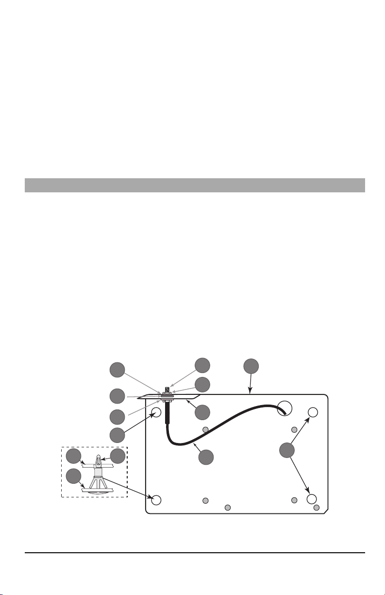
To assemble supplied mounting bracket,perform the following: (See Figure 1).
a.
Remove the 4 white plastic standoffs from the bag provided with the communicator kit.
b.
Insert the 4 standoffs through the back of the mounting bracket,into the holes at each corner. (The antenna
mounting tab should be facing away from you).
c.
Place the bracket on a flat, solid surface. Hold the communicator component side up and orient the 4 holes on the
communicator with the 4 standoffs protruding from the bracket. Push the communicator firmly and evenly onto the
standoffs until it is securely attached to the mounting bracket.
d.
Remove the panel front cover.
e.
Remove and discard the circular knockout located in the top-right section of the panel. (This hole will be used for
connection of the supplied radio antenna).
f.
Connect the supplied 5” (12.7 cm) antenna cable to the radio, by passing the connector through the hole on back
of the mounting bracket to the communicator board. Push the antenna connector firmly into the socket on the cellular radio. (See Figure 3).
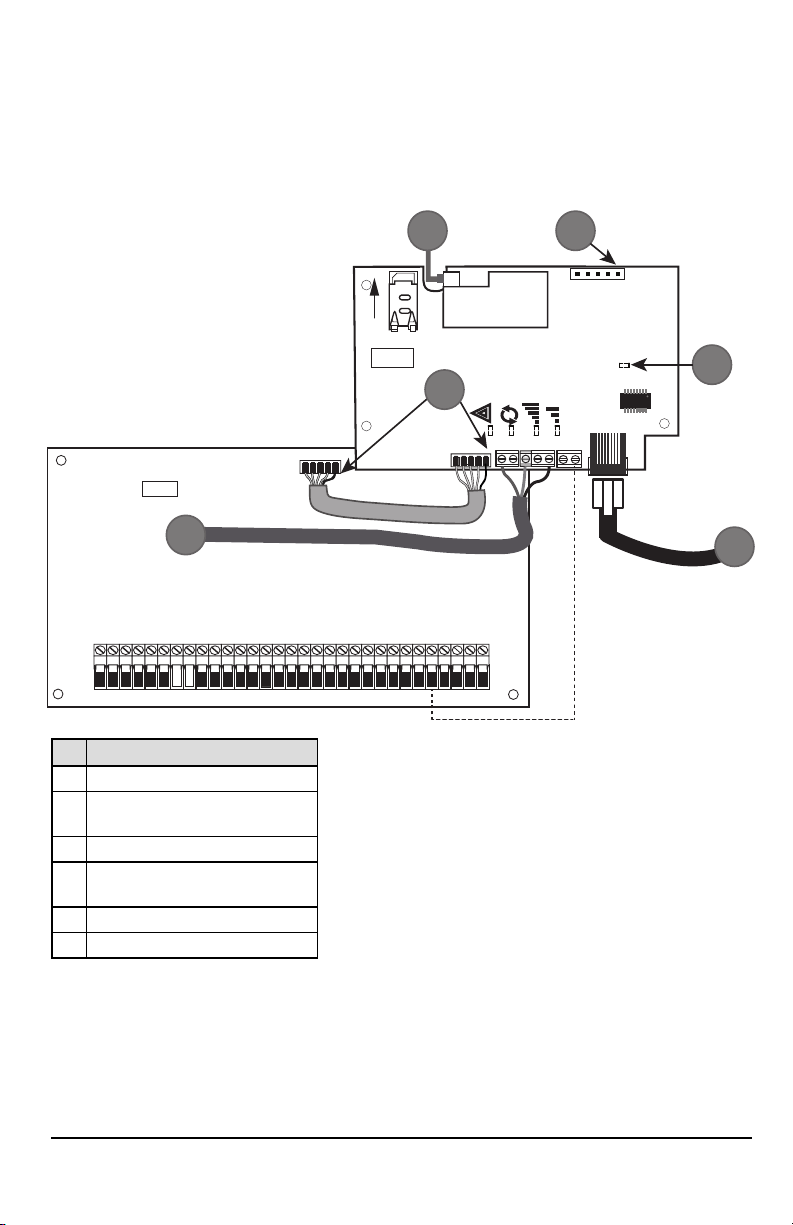
Figure 1: Communicator Mounting Bracket
7
Page 8
Item Description
1
2
3
1 External Antenna Screw Thread
2 Brass Nut
3 Brass Washer
4 Nylon Washer (flat)
5 Antenna Mounting Tab
6 Nylon Washer with bushing (thicker flat washer)
7 Antenna Cable
8 Mounting Holes
9 Mounting Plate
10 Communicator Board
11 Stand Off
2.
Install the Communicator into the panel:
a.
Attach one end of the PC-LINK cable to the panel PCLINK_2 header on the panel (red wire goes on the righthand pin of the panelPCLINK_2 header (see Figure 3)).
b. Insert theassembled communicator intothe panel.
NOTE: Ensure thatthe threaded antenna connection point is visible through the knockout hole at the topright of
c. Placethe nylon washer with bushing (thick flat washer) onto the threaded section ofthe antenna cable.Insert the
d. Place the second nylon washer (flat), followed by the brasswasher and the brass nut,onto the threaded section
e.
f.
g. Using light pressure (finger tight only), attach the supplied white quad band whip antenna to the threaded
the panel.
threaded section through the antenna mounting knockout hole at top right ofpanel.
of the cable, outside the panel. Tighten the assembly by hand only (finger tight only- do not over tighten the
antenna assembly).
Locate the screw hole on the right side wall of the panel. See Figure 2 "screw". Line up the assembled com-
municator with the right side wall ofthe panel and, using the screwprovided, secure the mounting bracketto the
panel.
Attach the other end of the PC-LINK cable to thecommunicator (red wire goes on theright-hand pin ofthe com-
municatorPC-LINKheader (See Figure3)).
antenna connection point at top of the panel.
Figure 2: HS2016/2016-4/2032/2064/2128 Control Panel
Item Description
1 PC-Link Cable Connector
Quad Band Whip Antenna - Use light pressure to
2
WARNING! - 3G2080(R) E/TL2803G(R)E/LE2080(R)/TL280LE(R) modules are power limited. Do not route any wiring
over the circuit board. Maintainat least 1in. (25.4mm) separation between circuit board and wiring. A minimum of ¼
in.(7mm) separationmust bemaintainedat allpoints between non-powerlimitedwiring and power limited wiring.
8
attach antenna fingertight only
3 Screw
Page 9
3.
AUDIO/DEFAULT
DSC
UA685
PC-LINK
PCLINK_2
COM
TL2803G(R)E
3G2080(R)E
TL280(R)E
TL280LE(R)
LE2080(R)
AC
AC
Z1 COM Z2 Z3 COM Z4 Z5 COM Z6 Z7 COM Z8
AUX+
BELL +
PGM1 PGM3
RING
T-1
HS2016/2032/2064/2128
3G/LTE Radio
UA621
L
o
c
k
1
RJ-45
GRN
YEL
TIP
R-1
BLK
RED
AUX -
BELL -
EGND
TX+
GND
TX-
RX+
RX-
SHLD
SIM
PGM2 PGM4
4
1 2
3
5
6
To electrically connect the communicator to the panel, perform the following steps (See Figure 3):
a.
Disconnect both ACpower and battery connections from the panel, and disconnect telephone line.
b.
Confirm that the SIMcard is inserted in the holder and locked.
4.
Install Network Cable (TLXXXXmodels only). Route the CAT 5 Ethernet cable through back of the panel and plug it
into the communicator’s RJ45 jack.
NOTE: Before leaving the premisesthe Ethernet communication lines must first be connected to an approved (acceptable
to local authorities) type NID.All wiring shall be performed according to the local electrical codes.
Figure 3: Communicator Wiring Diagram
Item Description
1 To External Antenna
AUDIO/ DEFAULT
2
Jumper pins 4 and 5 to reset
3 Network Link - Yellow
From NID use only CAT5 supervised
4
maximum cable length 100m (328 feet)
5 RS-232 to third party device
6 RED Wire
5.
Install the RS-232 connections (R models only). Ifusing the communicator with a 3rd party device, wire the con-
Input Ratings:
l +10.8V ~ +12.5VDC
l 90mA 3G2080(R)E/120mA TL2803G(R)E standby
l
l
l 100mA TL280(R)E
l 400mA alarm
DSC Panelminimumpower requirements:
l 16.5 VAC 40 VAtransformer
l 12 VDC 7Ah battery
90mA 3G2080(R)E/ LE2080(R)
120mA TL2803G(R)E/TL280LE(R)
nections as per the table below:
9
Page 10
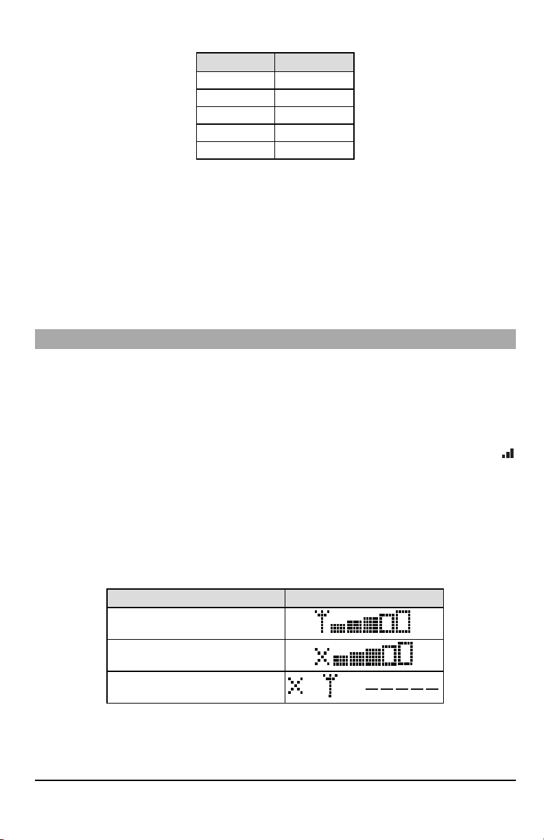
Table 3:RS-232 Connections
OR AND
3rdParty Device Communicator
TX (RED)* RX+
Unused RX-
RX (GRN)* TX+
Unused TX-
GND (BLK)* GND
* Wire colors based on the cable provided in the product box.
6.
Perform the following steps for initial power on of the panel with communicator installed:
a.
Reconnect the ACpower, telephone line, and battery + connector to the panel.
(The communicator and panel will power up together).
b.
Observe that the communicator’s red and yellow LEDs are flashing together while it initializes. The red and yellow
LEDs will continue to flash until the communicator has successfully communicated to all programmed receivers.
NOTE: During radio reset,the two green LEDs will flash alternately.
NOTE: Initialization may take several minutes to complete.Red and yellowLEDs will flash together during initialization. Do
not continue to next step until the red and yellow LEDs have stopped flashing. (If only the yellow LED is flashing,
there is a communicator trouble and the green LEDs are not valid for communicator placement test).
Correct trouble indicated by flashes on yellow LED before continuing. (See Table 7 for troubleshooting assistance).
7.
Perform the communicator placement testbelow.
8.
Mount the panel in final location indicated by placement test.
Communicator Placement Test
Cellular Communicator Models Only
To confirm thatthe cellular antenna location is suitable for radio operation,perform the placementtestas follows:
NOTE: It might be necessary to relocate the panel or install an optional extension antenna during this procedure, if the
radio signal strength is too low.
1.
Confirm that the yellow LED on the communicator is not flashing. Aflashing yellow LED indicates trouble on the communicator. See Table 7 to
2.
Confirm that the strength of the radio signal on the yellow LED and the 2 green LEDs on the communicator meet or
exceed the minimum signal level requirement. Minimum signal level: The yellow LED is OFF and the green LED 1
(furthest from the yellow LED) is ON (i.e., not flashing) for the panel location to be acceptable. For interpretation of
receiver strength on LEDs, refer to the table “Radio SignalStrength”.
Cellular Signal Strength Display - LCD Keypad only
The cellular network signal strength can be checked on the keypad LCDscreen by entering installer programming section
[850].The LCDwill indicatethe SIMcard activation status followed by up to fivebars of signal strength.This displaywill automatically update every three seconds. For the relationship between signal strength bars, CSQ level, and signal level in
dBm, refer to “RadioSignalStrength”.
troubleshoot and correct the cause of this trouble before continuing to the next step.
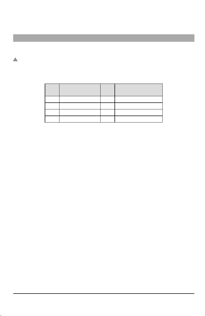
Table 4:Signal Strength Display
Description Display
SIM card active and current signal strength
SIM card inactive and current signal strength
Radio not registered
NOTE: If the required signal strength is too low with the panel in its current location, the panel must be relocated or an
external antenna is required.
Ifrequired, the following cellular extension antenna kits are available to the installer:
l GS-15ANTQ - 4.57m (15’) internal antenna extension kit (suitable for interior mounting).
l GS-25ANTQ - 7.62m (25’) external antenna extension kit (suitable for interior/exterior mounting).
10
Page 11

l GS-50ANTQ - 15.24m(50’) external antenna extension kit (suitable for interior/exterior mounting).
Specificinstructions for the installation of the extension antenna are included with the kit. Observe all the electrical safety
instructions regarding the installation of the antenna. All the wiring of the equipment shall be fully compliant with the local
rules and regulations.
3.
If required, install the antenna extension and perform the following steps to determine the best location for placement
of the antenna:
a.
Disconnect the white whip antenna from the panel.
b.
Attach one end of the antenna extension cable to the threaded antenna connector on the panel and the other
end to the external antenna.
4.
Move the extension antenna to various locations while observing the two green LEDs on the panel.
a. Continue to reposition the extension antenna until it receives an acceptable (minimum one green LED ON solid)
signal strength.
NOTE: Minimum strength is: green LED 1 flashing and yellow LED off.If green LED 1 is flashing, relo-
cation should be considered.
b.
Mount the supplied antenna extension bracket at the location that provides the best signal strength.
5.
Alternately, reposition the panel to improve signal strength. Dismount the panel and move it to another location to
achieve the required signal strength. Ifthe panel is relocated to improve signal strength, mount itin the new location.
6.
When final panel/antenna location is determined, continue at the Initial PanelProgramming section.
NOTE: If theSIM card is notactivated, placementtestwill indicate the signal strength of the nearest cellular tower.
NOTE: In between displaying signal strength, the signal strength LEDs will flash alternatelyif an inactiveSIM card is used.
The flashing indicates that themodule is attempting to attach to the cellular networkand will only lastbriefly.
Initial Panel Programming
Keypad Data Display
l
Section-Toggle Options: The number is displayed when toggle is ONand the number is not displayed when toggle is
OFF.(e.g., toggle options displays: [--3--6--]. Options 3 and 6 are ON, all others are OFF). Pressing keys 1 through 8 will
alternately turn the toggle ON and OFF.
l
HEX/DecimalData: Values that are provided with two defaults, separated by a “/” character, use the format: hexa-
decimal followed by decimal equivalent (e.g., default [0BF5/3061]). Hexadecimal numbers are shown, with all leading
zeroes, to the full field length defined for the number.
Entering HEX values at keypad
To enter HEX values at the keypad,press the * key before entering the HEX value. (e.g.,to enter “C” at the keypad,press [*]
[3])
Entering ASCII Characters at keypad
1.
Press [*]and use scroll buttons [<] [>]to display “ASCIIEntry” on the LCD screen.
2.
Press [*]to select ASCII entry mode.
3.
Use the [<] [>] scroll keys to display the desired character and press [*]to save and exit ASCII.
4.
Repeat the steps above to enter another ASCII character.
HS2016/2016-4/2032/2064/2128 Initial Programming
For detailed information, refer to panel manual section ‘Alternate Communicator Set-up’. These sections must be programmed at the panel keypad. Enter [*][8][Installer Code][SectionNumber]. Record any values that are modified from
their default,in theappropriate worksheets for the panel or communicator.
1.
In panel section [377] ‘Communication Variables’, subsection [002] ‘Communication Delays’, sub-subsection [1]
‘Communication Delay’, program 060 (seconds).
2.
In panel section [382] ‘Communicator Option 3’ set option [5] ON.
NOTE: If thisoption isOFF, the yellow statusLED on the communicator will indicate ‘Panel Supervision Trouble’ (2 flashes)
and the unit can not be programmed via the PC-LINK cable.
Activating the Communicator with C24 Communications
Installation of the 3G2080(R)E /LE2080(R) or TL2803G(R)E / TL280LE(R) in North Americarequires activationwith C24
Communications in order to operate. Please contact the central station (C24 Communications Master Reseller) to confirm
the required stepsto activate / program the communicator.
All communicator options mustbe programmed via C24 Communications,except the following Ethernet options which can
also be programmed using the keypad or DLS:
l [001] Ethernet IPAddress
l [002] Ethernet IPSubnet Mask
l [003] Ethernet Gateway IPAddress
11
Page 12
NOTE: The SIM activation with the carrier can take several hours to complete. It is recommended the activation be com-
pleted prior to arrival on the customer site to avoid possible installation delays.
Once theSIM activation is complete, the communicator willautomaticallyconnect and download itsprogramming from C24
Communications.
Communicator Status LEDs
The communicator has four on-board LED indicators. These include one yellow trouble LED, one red network connection
status LEDand two green signal strength LEDs.The LED meaning isdescribed in thissection.
Yellow Trouble LED
Thisyellow LED will flash to indicate a trouble on the unit.The number offlashes indicates the type of trouble. See the table
below for the coded flashes and the conditions whichwill activate the trouble status LED.
Table 5:Yellow Trouble StatusLED
# of
Flashes
2 Panel Supervision Trouble 7 Receiver Not Available Trouble
4 Not Applicable 8 Receiver Supervision Trouble
5 Cellular Trouble 9 FTC Trouble
6 Ethernet Trouble 12 Module Configuration Trouble
NOTE: Only the highestpriority trouble (2 flashes is the highestpriority trouble) is indicated. When this trouble is restored,
the nexthighesttrouble will indicate,if present.This will continue untilall troubles have been cleared (yellow LED is
not flashing).
The following paragraphs describe the conditions associated with each trouble:
Trouble
Panel Supervision Trouble (2 Flashes)
Thistrouble will be indicated when communication between the communicator module and the panel fails. If the module
can notcommunicatewith the panel (e.g.,loss ofpower to the panel) the communicator willsend the ‘Panel Absent Trouble
Event’ message to the central station receiver.When communication returns,a ‘Panel Absent Restore Event’ is sent by the
communicator to the central station receiver. The reporting codes are ET0001 for trouble and ER0001 for restore. The
panel absent eventalwaysuses the primary receiveraccount code when communicating to the central station.
NOTE: The panel supervision trouble/restore are internally generated eventsby the communicator. Trouble isgenerated if
the communicator misses 6 polls. Trouble isrestored on receipt of firstpoll fromthe panel.
Cellular Trouble (5 Flashes)
Thistrouble is indicated for any of the following 4 conditions:
1.
Radio Failure: Trouble is indicated after 8 failed attempts to communicate with the cellular radio.
2.
SIMFailure: Trouble is indicated after 10 failed attempts to communicate with the SIM.
3.
CellularNetwork Trouble: Trouble is indicated for loss of the registration to the network provider.
4.
Insufficient SignalStrength: Trouble is indicated if calculated average signal strength is too low. (Both green LEDs
are OFF). Trouble will clear when the calculated average signal strength is above minimum (i.e., > CSQ 5).
NOTE: If Option [851][005] Bit8 is Off, CSQ less than or equal to 4 will not trigger Cellular Trouble
Ethernet Trouble (6 Flashes)
Thistrouble is indicated when an Ethernet link between the transmitter and the local switchor router isabsent.This trouble
will alsobe indicated ifthe unit fails toget Dynamic Host Control Protocol (DHCP) settings from the DHCP server. (Not active
if Ethernet receiversare not programmed).
Receiver Not Available (7 Flashes)
Thistrouble is indicated if the unit is not able tosuccessfully initialize withany of the programmed receivers. Unprogrammed
receivers are excluded. This trouble is also indicated if the cellular receiver APNs have not been programmed in sections
[205] and [215].
Receiver Supervision Trouble (8 Flashes)
Thistrouble is indicated when receiver supervision is enabled and communication between the communicator module and
the receiver fails. Trouble is indicated if Ethernet 1 and/or cellular 1 issupervised and does not receive a heartbeat from the
# of
Flashes
Trouble
12
Page 13

receiver or if cellular issupervised and the unit does not receive an acknowledgment to 4 heartbeats sentto the receiver.
FTC Trouble (9 Flashes)
Thistrouble is indicated when the unit fails to communicate module events to the central station.Trouble isdisplayed after
the unit has exhausted all communications attempts to all programmed receivers for events generated by the communicator.
Module Configuration Trouble (12 Flashes)
This trouble is indicated when the system account code or the receiver account have not been programmed. Disabled
receivers are excluded.
Red Network Connection Status LED
TL2803G(R)E / TL280LE(R)
BLINKING: Indicates communications in progress.
l Once quickly for outgoing Ethernet transmission.
l Twice quickly to indicate incoming Ethernet ACK/NACK.
OFF:This is the normal state ofthe red network connection status LED.There are no networkconnection issues present.
ON:There is a problem with the Ethernet or the cellular network connection. LED will be ON if any of the following occur:
Ethernet cable is not connected,DHCP configuration times out,unit fails to get an IP address from the cellular network, or
Cellular connection has been reset.
(Green LED 1) (Green LED 2) and (Yellow LED) Signal Strength
NOTE: If the yellow LED is flashing, signal strength in table below is not valid.
See Table 7 for troubleshooting flashing yellow LED.
13
Page 14
Table 6:Radio Signal Strength
Signal
CSQ
Yellow
Green
Strength
Level
LED
LED 2
Green
LED 1
Signal
Level dBm
ActionRequired
Ifthis statuspersistsand the yellow
LED shows5 flashes,confirm that the
Radio
Not
Ready
N/A N/A
Alternate
Flashing
Alternate
Flashing
SIMcard is active.
Confirmcellular service is active in
N/A
area.
Relocatepanel or install external
antenna.
No Signal 0 ON OFF OFF -113 or less Check all antenna connections.
1 Bar 1 - 4
2 Bars 5 - 6 OFF OFF Flashing -103 ~ -101
3 Bars 7 - 10 OFF OFF ON -99 ~ -93
4 Bars
5 Bars 14 + OFF ON ON
Flashing
See
OFF Flashing -111 ~ -105
Note
11-
OFF Flashing ON -91 ~ -87
13
-85 and
Relocate panel or install external
antenna if yellow trouble LED shows
five flashes.
Location is OK.Cellular signal strength
is greater than CSQ7.
higher
NOTE: The communicatorwill indicate cellular trouble (yellow LED = 5 flashes) ifthe calculated average CSQ Level is 4 or
less.
Network Activity LEDs - Red and Green (TL2803G(R)E/TL280LE(R) only)
l
Ethernet Activity: Red LED will blink quickly once for transmit, or twice for receive.
l
CellularActivity:Green LED 2 will blink quickly once for transmit, or twice for receive
Communicator Reset/Update
Factory Defaults Reset
Restore the programming options for the communicator to the factorysettings by installing a hardware jumper. Perform the
following steps to reset the communicator:
NOTE: A jumper is required on AUDIO/DEFAULTpins 4 and 5 to resetthe hardware values.
1.
Remove panel front cover.
2.
Locate the AUDIO/DEFAULT 5 pin connector on the communicator board (see Figure 3).
3.
Apply a jumper to short the hardware default pins 4 and 5.
4.
Remove AC and DC power from the panel and then reapply power to the panel.
5.
Wait until the two green LEDs on the communicator begin flashing rapidly.
6.
Remove the jumper from the hardware default pins 4 and 5 (green LEDs will stop flashing).
7.
Replace the panel cover.
NOTE: The communicatorhas now been resetto the factorydefault values.
Firmware Update
The firmware ofthe device can be updated over cellular or Ethernet (remote or local updating):
l When the firmware update begins, all 4 LEDs are ON.
l During the firmware update process, the LEDs will cycle in a chaser pattern.
l During the firmware update process, the chaser pattern will briefly pause and resume again. This indicates firmware
verification check has passed, and application update will begin.
l After a successful update, the unit will automatically restart.
l Should the update fail, all 4 LEDs will flash ON,then OFF together at 1 second intervals.
NOTE: If the firmware update fails, restart the communicator by cycling power. For persistent update failures, contact tech-
nical supportfor assistance.
14
Page 15

Communicator Troubleshooting
NOTE: For additional details:
l Refer to section [983] for troubleshooting the firmware updates
l Refer to section [984] to view the trouble status
l Refer to section [985] for troubleshooting radio initialization
Table 7:Trouble Indications
Trouble
indication
No
Indication
Yellow LED
– ON Solid
Trouble LED
– 2 Flashes
Yellow LED
– 5 Flashes
Yellow LED
– 6 Flashes
Yellow LED
– 7 Flashes
Trouble
IndicatorDigit
N/A No Power
N/A No Signal
02
05 Cellular Trouble
06 Ethernet Trouble
07
Possible
Causes
Panel
Supervision
Trouble
Receiver Not
Available
l Check the power connections between the panel and the
communicator.
l Confirm PC-LINK cable is properly installed between
communicator and panel.
l Confirm that cellular network service is active in the area.
l Ensure the antenna is securely connected to the radio. Check
antenna stub cable is securely connected to the radio.
l If an external antenna is used, ensure the antenna is securely
screwed on to the antenna cable connector. Check external
antenna for damage or open/short.
l Check section [382] toggle option[5] is ON (Alternate
Communicator Enabled).
l Ensure the PC-LINK cable between the panel and communicator
is connected properly (not reversed) and is securely in place.
l Confirm that cellular service is available and active in the area.
l Check all antenna connections.
l Ensure average radio signal strength is CSQ5 or higher. (See
Table 7 ).
l Ensure the SIM card is properly inserted into the SIM card holder.
l Ensure the SIM card has been activated (could take up to 24 hrs
after install).
l If this trouble persists,relocate the panel (and communicator) or
install an external antenna extension kit.
l Check with the ISPto confirm Internet service is active in the area.
l Ensure the Ethernet cable is securely inserted into the RJ45 jack of
the communicator and the hub/router/switch.
l Check the link light on the hub/router/switch is ON. Iflink light is
OFF,start the hub/router/switch.
l If DHCP is used, ensure that the unit has an assigned IP address
from the server. In Section [851] [992] verify a valid IP address is
programmed. Ifnot, contact the network administrator.
l If problem persists, replace the Ethernet cable and RJ45
connector.
l Ensure that the Ethernet path has Internet connectivity.
l If using a static IPaddress, confirm that the gateway and subnet
mask are entered correctly.
l If the network has a firewall, ensure the network has the
programmed outgoing ports open (default UDP port 3060 and
port 3065).
l Ensure that all the receivers are programmed for DHCP or have
the proper IPaddress and port number.
l Ensure the cellular receiver APNs have been programmed with
the access point name provided by the cellular provider.
l If Common Mode is used, and only one path is initialized while the
other path is not successful, generate a manual test transmission
over both paths or power cycle the communicator to recover the
‘Receiver Not Available’ trouble.
Trouble Possible Solution
15
Page 16

Trouble
indication
Yellow LED
– 8 Flashes
Yellow LED -
9 Flashes
Yellow LED
– 12 Flashes
All LEDs
flashing
together
Red and
Yellow LEDs
flashing
together
Only Green
LEDs
flashing
Green LEDs
alternating
Trouble
IndicatorDigit
08
09 FTC Trouble
0C
N/A
N/A
N/A
N/A
Possible
Causes
Receiver
Supervision
Trouble
Module
Configuration
Trouble
Boot Loader
Failed
Initialization
Sequence
Hardware Default
Jumper
Radio Reset or
Radio
Initialization
Trouble Possible Solution
l This trouble is indicated when supervision is enabled and the unit
is not able to successfully communicate with the receiver.
l If this trouble persists,contact the central station.
l The unit has exhausted all communications attempts to all
programmed receivers for events generated by the communicator.
l Restart the system, if trouble persists, contact the dealer.
l This indication appears when section [021] system account code
or sections [101], [111], [201],and [211] receiver account code
have not been programmed. Ensure that a valid account code has
been entered in these sections.
l Disconnect power, then reconnect power to the communicator
module.
l The unit is still initializing, please wait while the unit gets its
programming and establishes a connection to all programmed
receivers.
NOTE: This processmay take several minutes tocomplete.
l The hardware default jumper is installed and must be removed.
See Figure 3.
l If this status persists and the yellow LED shows 5 flashes, confirm
that the SIM card is active.
16
Page 17

Limited Warranty
DigitalSecurityControls warrantsthe originalpurchaserthat fora pe riod of twe lve
months from the date of purchase, the produ ct shallbe free ofd efectsin materials
and workmanship under n ormal u se. During the warran ty period, Digital Security
Controlsshall,at itso ption, repairor replace any d efectiveproduct upon return of
the product to its factory, at no charge for labour and materials. Any replacement
and/or repaired parts are wa rranted for the remainder of the original wa rranty or
ninety (90) days, whichever is longer. The original purchaser must promptly no tify
DigitalSecurity Controls in writing that there is de fect in material or workmanship,
such written no tice to be received in allevents p rior to expiration of the wa rranty
period. There is absolutelyno warrantyon software and all software products are
soldasa user license und er the termsof th e software licenseagree ment included
with the prod uct. The Customerassumes a llresponsibilityfo r the proper selection,
installation, operation and maintena nce of any prod ucts purchased from DSC.
Custom products are on lywarranted to the extent that the yd o not function upon
delivery.In suchcases,D SCcan replaceor credit at itsoption.
International War ranty
The warran ty for international customers is the same as fo r any customer within
Canada and the United States, with the exception that Digital Security Controls
shallno t be responsible for anycustomsfe es, taxes,or VATthat may be due.
Warranty Procedure
To obtain service under thiswarran ty, please return the item(s)inq uestion to the
point o f purchase. Allauthorized distributo rsa nd dealershave a warranty program.
Anyone returning goods to Digital Security Controls must first obtain an authorizationnumber. Digital SecurityControls will not accept any shipment whatsoever
for whichpriorautho rizationhas not be en obtained.
Conditions to Void Warranty
Thiswa rranty app lies onlyto de fects inp arts and workmanshiprelating to normal
use. It does not cover:
l damage incurred in shipping or ha ndling;
l damage caused byd isastersuchas fire, flood, wind, earthquake o rlightning;
l damage due to causesb eyond the controlof DigitalSecurityControlssuch as
excessive voltage, mechan icalshock or wa ter da mage;
l damage caused byu nautho rizedattachment, a lterations, modificationso r
foreign objects;
l damage caused byp eripherals(unlesssuch pe ripherals were suppliedby
DigitalSecurityControls);
l defe ctscaused b yfailureto provide a suitableinstallationenvironment forthe
produ cts;
l damage caused byu se of the p roductsforpurposes other tha n th ose fo r
which itwas designed;
l damage from improper maintenance;
l damage arisingout ofany other abuse, mishandling orimproperapplication
of the products.
Items Not Covere d by Warranty
In addition to the items which void the Warranty, the following items shallnot be
covered byWarranty: (i)freight cost to the repair centre; (ii)products which are not
identified with DSC'sp roductlabel and lot nu mber or serialn umber; (iii)productsdisassembled or repaired in such a manner as to a dverselyaffect p erformanceor prevent adequate inspection or testing to verify any w arranty claim. Access cards or
tags returned for rep lacement underwarranty willbe credited orreplaced at DSC's
option . Products no t covered bythiswarran ty, orotherwiseout of warranty du e to
age, misuse, or damage shall be evaluated, and a repair estimate shall be
provided. No repairwork willbe pe rformed untila valid purchase order is received
from the Customer and a Return Merchandise Authorisation number (RMA) is
issued by DSC'sCustomerService.
DigitalSecurityControls’sliabilityfor failure to repairthe productunder this warranty
after a reasonable number of attempts will be limited to a replacement of the
produ ct, as the exclusive remedyfor breach o f warranty.Under no circumstances
shallDigital SecurityCon trols b e liable for any spe cial,incidenta l, or con sequential
damagesbased upon brea ch of warranty, breach of contract, negligence, strict
liability,or anyotherlegal theory. Such damagesinclude, but are not limited to, loss
of profits, lossof the product or any associated equipment, cost o f capital, cost of
substitute or rep lacement equipment, facilitiesor services,d own time, purchaser’s
time,the claimsof th irdparties, including customers,and injuryto property.Th e laws
of some jurisdictions limit or do not allow th e disclaimerof consequentialda mages. If
the laws of such a jurisdiction app lyto any claimby or against DSC, the limitations
and disclaimerscontained here shall be to the greatest extent permitted by law.
Somesta tes do not allow the exclusiono r limitation of incidenta l or consequential
damages, so tha t the ab ove may not app lyto you.
Disclaimer of Warranties
This warranty c ontains the entire warranty and shall be in lieu of any
and all other warranties, whether expres sed or implied (including all
implied warra nties of merc hantability or fitness for a particular purpose)
And of all other obligations or liabilities on the part of Digital Security
Controls Digital Security Controls neither assumes r esponsibility for,
nor authorizes any other person purporting to a ct on its behalf to modify
or to change this war ranty, nor to assume for it a ny other warranty or
liability concerning this product.
This disclaime r of war ra nties and limited warranty are governed by the
laws of the province of Ontario, Ca nada.
DigitalSecurity Controls recommends that the entiresystem be completely tested
on a regular basis.However, despite freq uent testing, and due to, but n ot limited
to, criminal tampering or electricaldisruption, it ispossiblefo rthisp rodu ctto fa ilto p erforma sexpected.
Installer’s Lockout
Anyproducts returned to DSC which ha ve the Installer’sL ockout option ena bled
and exhibitno other problemswillbe subjectto a servicecharge.
Out of Warranty Repairs
DigitalSecurityControls willat itsoption repair orreplace out-of-warranty products
which are returne d to its factory according to the following conditions. Anyone
returning goodsto DigitalSecurityControls must firstobtain an au thorization number. Digital Security Controls will not accept any shipment whatsoever for which
priorauth orization ha sn ot b een obtained .
Products which Digital SecurityCo ntrolsdeterminesto be repairable willbe repaired
and retu rned. A set fee which Digital Security Controls has predetermined and
which mayb e revised from timeto time, willbe charged fore ach unit repaired.
Products which Digital Security Con trols d etermines not to be repairable will be
replaced b ythe nearest equivalent p roduct availablea t that time. The current market priceof th e rep lacement product willbe charged for eachreplacement unit.
EULA
IMPORTANT - READ CAREFULLY: DSC Software purchased with or without
Products and Components iscopyrighted and is purchased und er the following
license terms:
ThisEnd-UserLicense Agreement (“EULA”)isa legalagree ment betwe en You(th e
company, individual o r entity who acquired the Software and any related Hardware) and DigitalSecurityControls,a division o f Tyco SafetyProdu ctsC ana da Ltd.
(“DSC”),th e manu facturerof the integrated securitysystems a nd the developer of
the software and anyrelated prod ucts or compon ents (“HARDWARE”) which You
acquired.
If the DSC software p roduct (“SOFTWARE PRODUCT”o r “SOFTWARE”) is intended to be accompanied by HARDWARE, and is NOT accompanied by new
HARDWARE, You may not use, copy or installthe SOFTWARE PRODUCT. The
SOFTWAREPRODUCT includes compute r software, and mayinclude associated
media, printed materials,and “online”orelectronicdocumentation.
Anysoftware provided along with the SOFTWAREPRODUCT tha t is associated
with a sep arate end-user license ag reement is licensed to You u nder the te rms of
that license ag reement.
By installing, copying, dow nload ing, storing, accessing or otherwise using the
SOFTWAREPRODUCT, You agree unconditionallyto be bound by the terms of
thisEULA,e ven if thisEULA isde emed to be amodificationof anyprevious arrangement or contract. If You d o not agree to the termsof thisEULA,DSC isunwilling to
license the SOFTWAREPRODUCT to You, and You have no right to useit.
SOFTWARE PRODUCT LICENSE
The SOFTWAREPRODUCT isprotected bycopyright lawsand international copyright treaties, as we ll as other intellectual property laws and trea ties. The
SOFTWAREPRODUCT islicensed , no t sold.
1. GRANT OF LICENSE This EULA grants You the following rights:
Software Installation and Use - For each license You acquire, You may have
onlyone copyof the SOFTWAREPRODUCT installed.
Storage/Network Use - The SOFTWARE PRODUCT may not be installed,
accessed, displayed, run, shared or used concurrently on or from different compute rs,including a wo rkstation, te rminal oro therdigitale lectronicd evice (“Device”).
In other words, ifYou have severalworkstations, You willhave to acquirea license
for each workstation where the SOFTWAREwillb e used.
Backup Copy -You maymakeback-up copiesof the SOFTWAREPRODUCT, but
You may only ha ve one copy per license installed at any given time. You may u se
the back-up copysolely for archival purposes. Except as expresslyprovided in this
EULA,You may not otherwisemake copiesof th e SOFTWAREPRODUCT, including the printed mate rialsaccompanying the SOFTWARE.
2. DESCRIPTION OF OTHERR IGHTS AND LIMITATIONS
Limitations on Reverse Engineer ing, Decompilation and Disassembly -
You may no t reverse engineer, decompile, or disassemble the SOFTWARE
PRODUCT, e xcept and onlyto the extent that suchactivityis expresslype rmitted by
applicable law no twithstanding thislimitation. You may not make any changes o r
modificationsto the Software, without the written permission of an officerof DSC.
You may no t remove any proprietary notices, marks o r labels from the Software
Product. You shall institute reasonable measures to ensure compliance with the
termsand con ditions of thisEULA.
Separa tion of Components - The SOFTWAREPRODUCT is licensed a sa single
produ ct. Its component parts may not be separated for use on more than one
HARDWAREu nit.
Single INTEGRATED PRODUCT - If You acquired this SOFTWARE with
HARDWARE,then the SOFTWAREPRODUCT islicensed with the HARDWAREas
a single integrated product. In this case,the SOFTWAREPRODUCT mayonly be
used with the HARDWAREas set forth in th isEULA.
17
Page 18

Rental - You may not rent, lease or lend the SOFTWAREPRODUCT. You may not
makeitavailableto others or po stito n a serveror we b site.
Software Product Transfer -You may transferall of You rrights underthis EULA
only as part of a permanent sale o r transfer of the HARDWARE, provided You
retain no copies, You transfera ll of the SOFTWAREPRODUCT (including all component parts, the media a nd p rinted materials, an y upgrades and this EULA), and
provided the recipient agrees to the terms of this EULA. If the SOFTWARE
PRODUCT is an upgrade, an y transfer must also include all p rior versions of the
SOFTWAREPRODUCT.
Termination -Without prejudice to any otherrights,DSC mayterminate th is EULA
ifYou fail to complywith the termsand conditions of this EULA.In suchevent, You
must d estroy all copies of the SOFTWARE PRODU CT and all of its componen t
parts.
Trade mar ks - Th is EULA doesnot grant You any rights in connection with any
trademarksor servicemarkso f DSC orits suppliers.
3. COPYRIGHT
Alltitlean d intellectual propertyrightsin and to the SOFTWAREPRODUCT (including but not limited to an y images, pho tographs, and text incorporated into the
SOFTWAREPRODUCT), the accompanying printed materials, an d any copies of
the SOFTWAREPRODUCT, are owned byDSC orits suppliers. You maynot copy
the printed materialsaccompanying the SOFTWARE PRODUCT. Alltitlea nd intellectualpropertyrightsinand to the content whichmay be accessedthrough u se of
the SOFTWAREPRODUCT are the propertyof the respectivecontent owner and
may be protected by applicable copyright or other intellectual property laws and
treaties. ThisEULA gran tsYou no rightsto usesuch conte nt. Allrights not expressly
granted u nderthisEULAa re reserved byDSC a nd itssuppliers.
EXPORT RESTRICTIONS - You agree that You willnot export or re-expo rt the
SOFTWARE PRODUCT to any coun try, person, or entity subject to Canadian
export restrictions.
CHOICE OFLAW - This Software License Agreement is governed by th e laws of
the Province of Ontario, Canad a.
ARBITRATION -All disputes arising in connection with this Agreement shall be
dete rmined by finala nd binding arbitration in accordance with the Arbitration Act,
and the parties agree to b e bou nd by the arbitrator’s decision. The placeof arbitration shallbe Toronto, Canada, a nd the langua ge ofthe arbitration shallbe English.
LIMITED WARRANTY
NO WARRANTY - DSC PROVIDES THE SOFTWARE “AS IS” WITHOUT
WARRANTY. DSC DOES NOT WARRANT THAT THE SOFTWAREWILL MEET
YOUR REQUIREMENTS OR TH AT OPERATION OF THE SOFTWARE WILL BE
UNINTERRUPTEDOR ERROR-FREE.
CHANGES IN OPERATING ENVIRONMENT - DSC shallnot be responsible for
problemscaused by changes in the operating characteristics o f the HARDWARE,
or for problems in the interaction of the SOFTWARE PRODUCT with non- DSCSOFTWAREor HARDWARE PRODUCTS.
LIMITATION OF LIABILITY; WARRANTY REFLECTS ALLOCA TION OF RISK
-IN ANYEVENT, IF ANYSTATUTEIMPLIESWARRANTIESOR C ONDITIONSNOT
STATED IN THISLICENSEAGREEMENT, DSC’SENTIRE LIABILITY UNDER ANY
PROVISION OF THIS LICENSE AGREEMENT SHALL BE LIMITED TO THE
GREATER OF THE AMOUNT ACTUALLY PAID BY YOU TO LICENSE THE
SOFTWAREPRODUCT AND FIVECANADIAN DOLLARS(CAD$5.00 ). BECAUSE
SOMEJURISDICTIONS DO NOTALLOW THE EXCLUSIONOR LIMITATION OF
LIABILITY FOR CONSEQUENTIAL OR INCIDENTAL DAMAGES, THE ABOVE
LIMITATION MAYNOT APPLYTOYOU.
DISCLAIMER OF WARRA NTIES - THIS WARRANTY CONTAINS THE ENTIRE
WARRANTYAND SHALL BE IN LIEUOF ANY AND ALL OTHER WARRANTIES,
WHETHEREXPRESSED OR IMPLIED(IN CLUDING ALL IMPLIED WARRANTIES
OFMERCH ANTABILITY OR FITNESSFOR A PARTICULAR PURPOSE) AND OF
ALL OTHER OBLIGATIONSOR LIABILITIESON THEPART OF DSC. DSC MAKES
NO OTHER WARRANTIES. DSC NEITHER ASSUMES NOR AUTHORIZES ANY
OTHERPERSON PURPORTING TO ACT ONITS BEHALF TO MOD8IFY OR TO
CHANGETHISWARRANTY,NOR TOASSUMEFOR ITANYOTHER WARRANTY
OR LIABILITY CONCERNING THISSOFTWAREPRODUCT.
EXCLUSIVE REMEDY AND LIMITATION OF WARRA NTY - UNDER NO
CIRCUMSTANCES SHALL DSC BE LIABLE FOR ANY SPECIAL, INCIDENTAL,
CONSEQUENTIAL OR INDIRECT DAMAGES BASED UPON BREACH OF
WARRANTY,BREACH OF CONTRACT, NEGLIGENCE, STRICT LIABILITY, OR
ANY OTHER LEGAL THEORY. SUCH DAMAGES INCL UDE, BUT ARE NOT
LIMITED TO, LOSSOF PROFITS,LOSSOF THE SOFTWAREPRODUCT OR ANY
ASSOCIATED EQUIPMENT, COST OF CAPITAL, COST OF SUBSTITUTE OR
REPLACEMENT EQUIPMENT, FACILITIES OR SERVICES, D OWN TIME,
PURCHASERS TIME, THE CLAIMS OF THIRD PARTIES, INCLUDING
CUSTOMERS,AND INJURYTOPROPERTY.
DSC recommends that the entire systembe completelytested ona regular basis.
However, despite frequent testing, and due to, but not limited to, criminal tampering o relectrical disruption, it ispossible for this SOFTWAREPRODUCT to fail to
performas expected.
Regulatory Information
Modification Statement
Digital Security Controls has not approved any chang es or modifications to this
deviceby the user.Any changes or modificationscould voidthe user’sau thority to
operate the equipment. Digital SecurityCo ntrols n’app rouve a ucun e modification
app ortée à l’appareilp ar l’utilisateur, qu elle qu’en soit la natu re. To ut chang ement
ou mod ification peuven t an nuler le droitd ’utilisation de l’app areilp ar l’utilisateur.
Interference State ment
Thisdevice complieswith Part15 of th e FCC Rules and Industry Cana da licenceexempt RSS standard(s). Operation issub ject to the following two conditions: (1)
thisd evice may not cau se interferen ce, and (2) th is de vicemust accept any interference, including interference that may cause unde siredoperation of the device.
Le présen t app areil e st conforme aux CNR d'Ind ustrie Cana da ap plicables au x
app areils rad io exempts d e licence. L'exploitation est a uto risée aux de ux conditions suivantes : (1) l'appare ilne d oit pas prod uire de b rouillage, et (2) l'utilisateu r
de l'app areild oit accepte r tou t brou illage radioélectrique sub i,même sile brou illage
est susceptible d'e n compromettre le fo nctionn ement.
Wireless Notice
Thisequipment complies withFCC an d IC radiation exposure limitsset forth for an
uncon trolled environment. The antenna should be installed a nd operate d with minimum distance o f 20 cmb etween the radiatora nd your b ody. Th istran smitter must
not be co- located or operating in con junction with any other a ntenna or transmitter.
Cet a ppareilestconforme aux limites d'expo sition aux rayonnemen ts de la IC pour
un e nvironne ment no n con trôlé. L'anten ne doitêtre installé de façon à garder un e
distance minimale de 20 centimètres e ntre la source d e rayonn ements et votre
corps. L'émette ur ne do itp as être colocalisé nif onctionner conjointemen t avec à
autre anten ne ou autre émetteur.
Antenn a gain mustbe b elow / Gainde l'antenne doitêtre ci-dessous:
Freque ncy
Band/Bande de
fréquence
GSM850 /FD D V 2.26 dBi -
PCS19 00 /FDD II 2.41 dBi -
LTEB2 - 2.76 dBi
LTEB4 - 2.82 dBi
LTEB5/ B12 / B13 - 2.45 dBi
FCC Class B digital device notice
Thisequipment has been tested and foun d to comply with the limits for a Class B
digitald evice, pursuant to part15 of the FCC Rules.These limitsare designed to
provide reasonab le protection ag ainst harmful interference in a residential installation. This equipment ge nerates uses and can radiate radio frequency ene rgy
and, ifnot installed and used inaccordance with the instructions, may cause harmfulinterference to radiocommunications.H owe ver, the re isno gu arantee that interference will no t occur in a particular installation. If this equ ipment does cause
harmful interference to radio or television reception, whichcan be determined by
turning the eq uipment o ff and on, th e user isencouraged to tryto correct the interference by one or more of the following measures:
-Reorientor relocate the receiving antenna.
-Increase the separation betwe en the equipment a nd receiver.
-Conn ect the equipment into an outlet on a circuit different from tha t to which the
receiverisconnected.
-Consultth e dealer or an expe rienced radio/TVtechnician for help
CAN ICES-3 (B) / NMB-3 (B)
TL2803G (R) E - EU /3G2080 (R) EEU/TL280 (R)E
FCC ID:F5316TL2803GRE FCC ID:F5317TL280 LER
IC: 160A-TL2803GRE IC:160A-TL280 LER
Notes for EN50131-1:2006/A1:2009 Compliant installations:
ModelsTL 2803G (R)E-EU/3G2080 (R)E- EU/TL280(R)E are an SPTType Y - the
module is mounted within CIE or PSh ousingand it receivespower from the compatible CIE o rPower Supplysource that are incompliance with EN50131-6 :2008
Type A requirements for a Grade 2, Class II app lication. This produ ct has no
replacement pa rts and softwa re programmable options are accessible at level 3
(installer mode),section [851].
The TL280 3G(R)E-EU/3G208 0 (R)E-EU/TL28 0(R)E connects to compatible DSC
alarm control panels using the DSC proprietary serialinterface an d proto col PCLink(converted alsoto RS-422). The modu leope ratesin pass-through mode and
itdoes acknowledge the alarm to thecompatible control pane l a fter a n acknowledgement ha sb een received fromthe compatiblea larmreceiver.
1. The TL280 3G(R)E-EU/3G208 0(R)E-EU/TL280(R)Emodule ismonitored
bythe controlp anela nd it isp rogrammed via the programming menu (* 8,
section [85 1] in th e controlpanel. The interface isconne cted to the PCLinkbus as shown in th e diag ramincluded in thismanua l.
TL2803GRE, TL2803GE,
3G2080RE, 3 G208 0E
LE2080(R)/TL280 LE(R)
TL280LE, TL280LER,
LE2080, LE2080R
18
Page 19

2. The HSPA3G Cellularpath isimmune to conducted and radiated RFfields
with levelsup to 10V/mas te sted p er EN50130-4 Stand ard.
3. The TL280 3G(R)E-EU/3G208 0(R)E-EU/TL280(R)Emodule conforms
with radiated emissionslevelsfor ClassBequipment as persta nda rds
EN61000- 6-3/EN55022/CISPR22.
4. The TL280 3G(R)E-EU/3G208 0(R)E-EU/TL280(R)Emodule uses
AES128 encryption an d heartbeat supervision fo rHSPA3G Cellularcommunication paths and it meets securitylevelsS2asper EN50136-2:2 013 .
It also uses authe ntication for eachmessage exchanged with the compatible receivereq uipment a t ARC and it meetslevel I2 for information
security.
5. The 3G2080(R)E-EUmodule hasonlyone communicationpath:
HSPA3G Cellular communication pa th using900 /1800/2100MHzPublic
CellularNetwo rk.The HSPA3G Cellularcommunicationpath that can be
used in a standalone mode inconjunction with aDSCalarmsystem(compatible DSCalarmcontrolpanelmodels:HS2128/06 4/0 32/016 ). The supported ATScon figuration is:customcate goryC.
6. The TL280 (R)Emodule hasonlyone communicationpath: Ethernet communication path usingInternet. The communication path that can be used
ina standalone mode in conjunction with a DSCalarmsystem(compatible
DSC alarmcon trol panel models: HS212 8/0 64/032 /016). The supporte d
ATSconfiguration is: customcategoryC.
7. The TL280 3G(R)E-EUmodule hastwo communication pa ths: HSPA3G
Cellularcommunication path using9 00/180 0/2100 MHzPublicCellularNetwork and Ethernet communication pa th u sing Inte rnet. The communication paths can b e used in a standalone mode in conjunctionwith a
DSC alarmsystem(compatible DSC alarmcontrol panel models:
HS2128/06 4/0 32/016 ). The supported ATSconfiguration is: custom categoryC.
8. TL2 803G(R)E-EU/3G2080(R)E-EU/TL280 (R)Eh as been tested forcompliance in conjunction withthe following applicablesta nda rds: EN501361:20 12, EN501 36-2:2013, EN50131 -10:2 014, ATSconfiguration: C.
For EN501 31-1:2006/A1:200 9 compliant installations, the following programming
option sshallbe setasdescribed.
Supervision Heartbe at: shallbe set to180 seconds
NOTE:The compatible receiverat ARClocation shallhave supervision window programmed for 180 seconds. TL2803G(R)E-EU/3G2080 (R)E-EU/TL 280(R) E has
been certified by TELEFICATION in accordan ce with EN50131- 1:2 006/A1:2009,
EN50131-10 :20 14 requirements for Grade 2, ClassII an d EN50 136-2:2013 Configuration: C
ATS Custom Category C Level
EN50136-1:201 2 Anne xD TableD.1 D3
EN50136-1:201 2 Anne xD TableD.2 M3
EN50136-1:201 2 Anne xD TableD.3 T4
EN50136-1:201 2 Anne xD TableD.4 A4(De pending on cellularcarrieru sed)
S2 (use AES- 128 and
EN50136-1:201 2 Anne xD TableD.5
auth entication/sequ entialinformation in
each message transmitted to the SG
receiver)
EN50136-1:201 2 Anne xD TableD.6 I2 (use AES-128 encryption)
Use single communication path fo r
EN50136-1:201 2 Table 1
models 3G2080 (R) E- EU (cellular
netw ork), TL280 (R) E (Etherne t port)
and two communication paths for model
TL2803G(R)E-EU(cell/Ethernet).
EN50136-1:201 2 Table 4 ATSfailure reported to ARC
EN50136-1:201 2 Table 5
EN50136-1:201 2 Table 6
ATS failure reported to AS (DSC
compatible control pa nel
HS2128/HS20 64/HS2032/HS20 16)
There is no recording of availability
failure
EN50136-2:201 3 Table 1 No logging fun ction provided
EN50136-2:201 3 Table 2
No memory provided for logging
function
EN50136-2:201 3 Table 3 ATSfailure reported to ARC
SIMPLIFIEDEU DECLARATION OF CONFORMITY
Hereb y,TycoSafety Products Ca nad a Ltd declares that the radioe quipment type
isin compliance with Directive 2014/53/EU. The fulltext of th e EU declarations of
conformityfor the models mentioned below are available at the following internet
addresses:
TL2803G(R)E-EU-h ttp://dsc.com/pdf/1605003
3G2080(R)E -EU-h ttp://dsc.com/pdf/16050 04
Frequency Band Maximum Power
EGSM900 890.0 MHz- 91 4.8 MHz Class4 (2W)@ 900MHz, GSM
EGSM900 880.2 MHz-88 9.8 MHz Class1 (1W)@ 18 00MHz, GSM
DCS180 0 1710.2MHz -1784.8MHz ClassE2 (0.5W)@ 900MHz, EDGE
WCDMA (Band VIII) 882.4MHz -
912.6MHz
ClassE2 (0.4W)@ 1800MHz, EDGE
WCDMA2100 (Band I) 19 22.4MHz -
1977.6MHz
Onlymodels TL2 803 GRE-EU,TL2803GE- EU, 3G20 80RE-EU, 3 G208 0E-EU are
CEcompliant.
Europea n single point of contact: Tyco Safety Products, Voltaweg 20, 6101 XK
Echt,Neth erlands
UL/ULC Installation Requirements
NOTE:For equipment used at the protected premises and inte nded to facilitate IP
communications (hubs, routers, NIDs, Digital Subscriber Line (DSL), cab le
modems),2 4 hou rbackup po wer is required. Whe re such cannot be facilitated, a
seconda ry(back-up) communicationchann el isrequired.
Domain Name Service (DNS) progr amming is not permitted in UL16 10
listed sy stems .
Technical Specific ations
The input voltage to the Communicator can b e drawn from the Underwriters Laboratories/UnderwritersLaboratories Can ada (UL/ULC)listed controlp anel.
Notes for using Private, Corporate , andHigh Speed Data Networks:
Networkaccessand domain accessp olicies shallb e set to restrictunau thorizednetwork access, and spoofing or Denial of Service (DoS) attacks. Select an Internet
Service Provider(ISP)that hasred undant servers/systems, back-uppower, routers
with firewalls enabled, and methods to identify and protect against DoS attacks
(e.g., via spoofing).
Notes for using Public Switched and Cellular Dat a Networks:
Communication channelsshallb e facilitated such th at the communicator will restrict
unauthorized access, which could o therwise compromise security. The communicator shallbe located in a secured area.
• For ULC Residential Fire and Burgla ry applications the TL2803G (R)
E/3G2080(R)E/TL280(R)E/LE2080(R)/TL280LE(R)can be usedasprimary communication channel viaeither cellularorEtherne t or asa back-up in conjunctionwith
the Digital Alarm Communicator Transmitter (DACT). Test transmission every 24
hoursshallbe enabled on each channel.
• For ULC Comme rcial Fir e and Burglary applications the TL2803G (R)
E/3G2080(R) E/TL280(R) E/LE2080 (R)/TL280LE (R) can be used as a passive
communicationmod ule with the following securitylevels:
l P1(each channe lcellularor Etherne t isindepende nt)
l P2(cellular and Ethernet in back-up configuration, panelsection [851][00 5]
togg le option [5]OFF).
l P3(cellular and Ethernet in red undant configuration, panel section [8 51]
[005 ] toggle option [5] ON).
The communicator can also be used as an active communication system with the
securitylevelsA1-A4 (eachchannel cellular or Ethe rnet independe nt ortoge ther in
a back-up/redundant configuration). For active line security systems AES128 bit
encryption sha llbe enabled (at th e monitoringstation receiver)and the supervision
heartbea t rate shallbe set as 90 seconds (panel section [851][0 04] = 0 05A/90).
The sup ervision w indow at the SignalReceiverCenter (SRC)'sreceiver shallbe programmed as maximumof 180 (00 B4/180) second s.
NOTE: For ULC commercial fire passive communication, encryption shall be
enabled,
• For UL Residential Fir e and Burglary a pplications th e TL2803 G (R)
E/3G2080R/TL280(R)E/LE2080(R)/TL280LE(R)can be used asthe primarycommunication channel via either cellular or Ethernet, or as a back-up in conjunction
with the DACT (30 daytest tran smissionisrequ ired on each chan nel).
• For UL Commerc ial Burglary applications the TL2803G(R) E/ 3 G208 0R /
TL280(R)E / LE2080(R) / TL280LE(R) canbe used asdual signalling line communication system (cellular an d Ethernet channels used in redun dant configuration),standard line securitya nd asencrypted line security.
• The supervision he artbe at shall b e enab led (panel section [851][0 05] toggle
option [1] (Ethernet)a nd/or toggleoption [2] (cellular) shallbe ON), toggle option
[3] (supervision type) shallbe ON and the sup ervision h eartbeat rate shallbe selected as13 5 (0087/135) seconds. Option [004] = 0 087. The sup ervision w indow at
the supervising station shall b e maximum200 (00C8/200) secon ds. For encrypted
line security systemsthe en cryption AES128 bitsha ll be enabled at the monitoring
station receiver.
• For UL Commer cia l Bur glar y installations, the TL2803G (R) E/3G2080 (R)
E/TL280(R)E/LE2080 (R)/TL2 80LE(R) is listed asa primary (sole) communication
means (hea rtbeat must b e ena bled) or for supplementary (back-up) u se in con junction with a Plain Old Teleph one Service (POTS)lined ialer.When the heartbeat
transmission over the Ethernet or cellular networkis e nabled, u sing the TL28 03G
(R)E/3G2080 (R) E/TL280 (R) E with a compatible control un it listed for stand ard/encrypted line security, it canp rovide line securityfor the alarmsystemo ver the
primaryline.
•The TL28 03G(R)E/3G2080 (R)E/TL280(R)E/LE2080(R)/TL280LE(R)isa lsosuitable to be used with a compatible control unit listed for dual line security transmissionwhen used in conjunction with a DACT ora Public Switched Data Network
(PSDN) transmitter, where the PSDN provides the line security and is the primary
line. In this mode, alarmsignals are required to be sent simultaneously over both
communicationmethods.
Class 3 (0.25W) @ 900 /2100MHz,
WCDMA
19
Page 20

© 2018 Tyco SecurityProducts.All RightsReserved.
Tech Support: 1-800-387-3630 (Canada & U.S.) or 905-760-3000
www.dsc.com
The trademarks, logos, and service marksdisplayed o n thisdocument are registered in the Un ited States[or other countries]. Anymisuse of the trademarksis strictly
prohibited and Tyco will a ggressivelyenforceits intellectualprope rtyrights tothe fullest extent of the law, including pursuitof criminalprosecution w herever necessary.Alltrad emarksnot owned by Tyco are the property of theirrespectiveo wne rs,and are used withp ermission or allowed un dera pplicable laws.
Product offerings and specificationsare subjectto change without n otice. Actual products mayvaryfrom ph otos.Not a llprod ucts include allfeatures. Availability variesbyregion; con tact yoursalesrep resentative.
Page 21

Pour télécharger le manuel complète et enregistrer votre produit, visitez
dsc.com/m/29009554 ou scannez le code QR pour le droit.
TL280LE(R)
Communicateur d’alarmes double voie Internet et LTE/HSPA
Communicateur
LE2080(R)
Communicator d'alarmes LTE/HSPA
3G2080(R)E
Communicateur d’alarmes Cellulaire HSPA
TL2803G(R)E
Communicateur d’alarmes double voie Internet et LTE/HSPA
TL280(R)E
Communicateur d‘alarmes sur Internet
Guide d'installation 5.X
Avertissement: Le présent manuel contient des informations relatives aux limitations concernant l'utilisation et les fonc-
tionnalités du produit ainsi que les limitationsde la responsabilité du fabricant. Lisez attentivementle manuel dans son intégralité.
Tous les modèles ne sont pas disponiblessur tous les marchés.
Page 22

AVERTISSEMENT: à l’attention de l’installateur, veuillez lire attentivement
Remarque pour les installateurs
Les avertissements de cette page contienn ent des informations vitales. En tant
que seul individu en contact avec les utilisateurs du système, c’est à l’installateur
qu’incombe la responsabilité d’attirer l’atten tion des utilisateurs du système sur
chaqu e élément de cette miseen garde.
Pannes de système
Ce système a été soigneusement conçu pour être au ssiefficace que possible.To utefois, dans des circonstances impliquant un incendie, un cambriolage ou tout
autre cas d’urge nce, ilse peu t qu’ilne fournisse pasde protection. Tout système
d’alarmeq uel qu’ilsoit peut être délibérément saboté ou peut ne pas fonctionner
commeprévu pou rplusieursraisons.Certainesde ces raisons sont notamment:
Acc ès par des intrus
Des intrus peuvent entrer par un point d’accès non protégé, contourner un dispositifd e détection, échappe r à une détection en se déplaçant dan s une zone
insuffisamment couverte, déconnecter u n dispositif d’alerte, ou interférer avec le
systèmeou empêcher son fo nctionnement normal.
Panne d’un é léme nt
Bienq ue tous lese fforts aient été faits po ur rend re le systèmeaussifiableque possible,le système peut malfonctionner à causede la pann e d’un élément.
Limites de f onctionnement des dispositifs de fréquence radio (sansfil)
Les signau x peuvent ne pa sa tteindre lerécepteur dans to utes les circonstances
qui pourraient inclure des objets métalliques placés sur ou à proximité du trajet
radio, ou le brouillage délibéré ou commis par inadvertan ce causant une interférence du signalradio.
Connaissances criminelles
Ce système contient des fonctions de sécurité reconnue s efficacesau moment de
lafabrication. Ilestpossibleq ue despersonnes ayan t de sintentionscriminelles élaboren t de stechniques quiréduisent l’efficacité d e ces fonctions. Il est important de
vérifierle systèmed e sécurité rég ulièrement pour garantirqu e ses fon ctions restent
efficaces, qu’ilestmis òjourou qu’ildoitêtre remplacé s’ils’avère qu ’ilne fournit pas
laprotection attendue.
Pannes des batter ies rem plaçables
Les transmetteurs sans fil de ce système ont été conçus pour fournir plusieurs
années d’auto nomie de batterie dans des conditions normales d’utilisation. La
durée de vie de la batterie dép end de l’environnement de l’appareil, de son utilisation e t du type de batterie. Les conditions ambiantes telles que l’humidité élevée, des températu restrès élevéesou très ba sses, ou de grossesdifférences de
température peuven t réduireladurée de vie de labatterie.Bienque chaque appareil de transmission possède un dispositif de surveillance de batterie faible qui
indique à quel moment la batterie d oit être remplacée, ilpeut ne pas fonctionn er
commeprévu. Un entretien etdes testsréguliersmaintiend ront le système dans de
bonnes conditionsde fonctionn ement.
Mauvaise installation
Un système de sécurité d oit être correctement installéafin de fournirune protection
adéqua te. Chaqu e installation doitêtre e xaminée parun professionne ld e la sécuritépours’assurer que tous les points d’accèsetzones sont couverts. L es serrures
et les loque tssurlesportes et fenêtres do ivent être bien fermése t fonctionne r normalement. Les fenêtres, portes, murs, plafond s etautres maté riaux de construction doivent être suffisamment solides pour assurer le niveau de protection
attendu . Un nouvel e xamen doit être effectué pen dant et après toute construction. Un examen parledépartement de police et/ou des sapeurs-pompierse st fortement recommandé sice service est offert.
Test insuffisant
La plupart desproblèmes quipourraient empêcherun systèmed ’alarme de fonctionne rnormalement p euvent être découverts en testant et en entretenant le système régulièrement. L’ensembledu système de vraitê tre testé hebdo madairement
et immédiatement après une effraction, une tentative d’entrée par effraction, un
incendie, u ne tempête, un tremblement de terre, un accident ou toute sorte de
construction à l’intérieur ou àl’extérieurdes lieux.Le testdoit inclureto us les appareilsde détection, claviers, consoles, dispositifs d’indication d’alarme ainsique tout
autre dispositif d’exploitation faisant partiedu système.
Insuffisance de tem ps
Ilpeut yavoirdes circonstances où le système fon ctionne commeprévu maisoù les
occupan ts ne seront pasprotég és à cause de leurincapacité à rép ondre au xavertissementsdans u n temps alloué. Si le système est connecté à u n poste de télésurveillance à distance, l’intervention peut ne pasa rriver à te mpsp ourp rotéger les
occupan ts ou leursbiens.
Détecteurs de mouvement
Les déte cteurs de mouvement ne détecten t le mouvement que dans les zones
désignées, conformément au x instructions d’installation. Ils ne peuvent pas distingue rlesintrus desoccupants. Le sdéte cteurs de mouvement ne fournissent pas
de protection volumétrique deszones. Ils ont de multiples rayonsde détection et
lesmouvementsne peuventêtre détectésque d ans des zones non o bstruées et
protégée s par ces rayons. Ils ne peuven t déte cter les mouvements qui se produisent derrière les murs, plafon ds, sols, po rtes fermée, cloisons vitrées, portes
vitréesou fenêtres.Tout typede sabota ge,qu’ilsoit intentionne lo u non, comme le
camouflage, la peinture ou la vaporisation de substances surles objectifs, miroirs,
fenê tres ou toute autre partie du système de détection empêchera son fonctionne ment normal.
Les dé tecteurs de mouvement à infrarou ge pa ssiffon ctionnent en dé tectant les
chang ements de température. Cependant, leur efficacité peut être réduite
lorsque la température ambiante s’approche ou dépasse latempérature d u corps
ou s’ilexistedes sources de chaleur intentionnellesou non intentionn ellesdans ou
près de la zone de déte ction. Certainesde ces sourcesde chaleur peu vent être
des dispositifsde chauffage , radiateurs, fours, barbecues, cheminées, lumière du
soleil, dispositifsd’évacuation de vapeur, éclairages, etc.
Panne de courant
Les éq uipements de contrôle, lesdétecteu rs d ’intrusion,les d étecteurs de fumée
et bien d’autresdispositifsde sécuriténécessitent u ne alimentation électrique adéquate pour fonctionner normalement. Si un appareil fonctionne grâceà des batteries, ile st possible que celles-ci faiblissent. Même si les batteries ne sont pas
faibles, elles d oivent être chargées, en bon état et installées correctement. Si un
appareilne fonctionne que p ar alimentation secteur, tou te interruption, même très
brève, rendra cet appa reilinopérant pend ant ladu rée de la coupure d e couran t.
Les coup ures de courant, quelle qu’en soitla du rée, sontsouvent accompagné es
par des fluctuations de tension quipeuvent end ommager les é quipements électroniquestels que lessystèmes de sécurité.À la suite d’une coupure de courant,
effectuez immédiatement u n te stcomplet du système pour vous assurer que le système fonctionne correctement.
Sécurité et assurance
Sanstenircompte d e ses capacités, un système d’alarme ne constitue pasun substitut à une assurance surlap ropriété ouu ne assurance vie. U n système d’alarme
ne doit pas empêche r lesprop riétaires, locatairesou autres occupants d’agir p rudemment afin d’éviterou d e minimiserles effets nuisibles d’une situation d’urgence.
Détecteurs de fumée
Les dé tecteursde fu mée qu ifont p artie du système peuven t ne pasbien alerter les
occupan ts d’un e ndroite n feu po ur un certainnombre d e raisons, dont :Les détecteurs de fuméepeu vent avoir été mal installés ou po sitionnés. La fumée peu t ne
pas po uvoiratteindre les détecteursde fumée, parexemple danslecasd ’un incendie dans une cheminée, murs ou toits, ou de l’autre côté de portes fermées. Les
déte cteurs de fuméepeu vent ne pasdétecter la fumée provenant d’incendies à
un autre n iveau de la résidence o u du bâtiment.
Tous les incendies diffèrent p ar la q uantité de fumée produite et le taux d e combustion. Les détecteurs de fumée ne peuvent pas détecter de la même manière
tous les types d’incend ie. Les détecteu rs d e fumée ne fournissent pas d’avertissement opportun d’un incendie causé paru ne impruden ce ou un manque de
sécuritételsq ue fumerdans un lit, e xplosionsviolentes, fuites de gaz,mauvais rangement de produits inflammables, circuits é lectriques surchargés, enfants jouant
avec des allumettes, incendiesprovoqué s.
Même si le détecteur de fumée fon ctionne comme prévu, dans certaines circonstancesle préa vis n’est pas suffisant pour permettre à tous les occupa nts de
s’enfuirà tempspouré viterles blessures ou lamort.
Lignes téléphoniques
Si les lignes téléphoniques sont utilisées pou r transmettre des appe ls, elles
peuvent être hors d'usag e ou o ccupés pendan t un certaintemps. Un intrus peut
également coup er la ligne téléphon ique ou provoquer son dérange ment par des
moyensplussophistiqués parfoisdifficilesà détecter.
Dispositifs d’aver tissement
Les dispositifs d’avertissement tels que les sirènes, cloches, avertisseurs ou
lumières stroboscopiques p euvent ne pas avertir les gensou ne pas réveiller une
personne endormie s’ily a un mur ou une porte fermée. Siles dispositifs d’avertissement sont p lacés àu n autre éta ge d e larésidence ou du local, il esta lors probable que les occupa nts ne seron t pas alertés ou réveillés. Les dispositifs
d’avertissement sonores peuvent être atténués par d’autres sources sonores
tellesque les chaînes stéréo, radios, télévisions, climatisations, autres app areils ou
par le trafic routier. Les dispositifs d’avertissement sonores, même bruyants,
peuvent ne pa sêtre entendusp ar une pe rsonne malentend ante.
22
Page 23

Généralités
Ce manuel d’installation doit être utilisé conjointement avec la centrale. Toutesles instructions spécifiées dans ce dernier
manuel doivent être respectées. La Centrale est appelé «centrale» dans tout ce document. Ce manuel d’installation fournit les informations de base de câblage, de programmation et de dépannage.
L’équipement est fixé, accroché au mur et doit être installé dans la position indiquée dans ces instructions. Le boîtier de
l'équipement doit être complètement assemblé et fermé, avec toutes les vis et toutes les languettes nécessaires, et il doit
être fixé à un mur avant d'être utilisé.Le câblage interne doitêtre acheminé de façon à éviter:
l Des contraintes excessives sur les câbles et les bornes de connexion,
l Les interférences entre les câblages de puissance limitée et ceux de puissance non limitée,
l Le relâchement des branchements des bornes,
l Des dommages à l’isolant du conducteur.
AVERTISSEMENT: N'installezjamais ce matérielpendantun orage!
Consignes de sécurité
L’installateur doitpréciser à l’utilisateur du système chacun des pointssuivants:
l N’essayez pas de réparer ce produit. L'ouverture ou le retrait des capots peut exposer l'utilisateur à des tensions dan-
gereuses ou à d'autres risques.
l Les interventions ne peuvent être effectuées que par du personnel formé à cet effet.
l Utilisez uniquement des accessoires agréés avec cet équipement.
l Ne pas rester à proximité du matériel pendant son fonctionnement.
l Ne pas toucher l’antenne externe.
Informations sur le modèle
Ce manuel concerne les modèles de communicateursd’alarme suivants:
Les modèles TL2803GRE- EU, TL2803GE-EU, TL280RE- EU, TL280E- EU, 3G2080RE- EU, 3G2080E- EU (fonc-
tionnement à 900/2100MHz) et 3G2080E-EU sont destinés au marché européen et couvrent les bandes suivantes:
900/2100MHz.
Les modèles TL2803GRE-AU, TL2803GE-AU, TL280RE- AU, TL280E- AU, 3G2080E- AU et 3G2080RE-AU (fonc-
tionnement à 850/2100MHz) sont destinés aux marchés australien, néo-zélandais et brésilien, et couvrent les bandes
suivantes:850/2100MHz.
REMARQUE: Seuls les modèles TL2803GE-AUet 3G2080E-AU sonthomologués Anatel pour un usage au Brésil.
Les modèles TL2803GRE, TL2803GE, TL280RE, TL280E, 3G2080RE et3G2080E (fonctionnement à 850/1900MHz)
sont destinés au marché nord- américain et sud-américain (à l’exclusion du Brésil) et couvrent les bandes suivantes:
850/1900MHz.
REMARQUE: Seuls les modèles TL2803GE et 3G2080E sont homologués CNCpour un usage en Argentine.
Les modèlesTL280LER,TL280LE,LE2080R, LE2080 sont destinés au marchénord-américain et prennent en charge les
bandes LTEB2,B4, B5, B12 etB13, ainsi que lesbandes W-CDMAB2 et B5.
Bande Bande d’émission (Tx) Bande de réception (Rx)
LTEB2 1850- 1910MHz 1930 - 1990 MHz
LTEB4 1710- 1755MHz 2110 - 2155 MHz
LTEB5 824 - 849 MHz 869 - 894 MHz
LTEB12 698 - 716 MHz 728- 746MHz
LTEB13 777 - 787 MHz 746- 756MHz
UMTSB2 1850- 1910MHz 1930- 1990MHz
UMTSB5 824 - 840 MHz 869- 894MHz
Les références aux modèle TL280(R)E, TL2803G (R) E, 3G2080 (R)E, TL280LE(R) et LE2080 (R) contenues dans ce
manuel s’appliquent à tous lesmodèles spécifiés sauf indication contraire. Lesnoms de modèles se terminant par la lettre
«R» sontdotés d’une interface intégrée RS-232 qui permetune connexion aux applicationstierces locales.
Le modèle TL280(R) E/TL2803G(R)E/3G2080(R)E/TL280LE(R)/LE2080(R) prend en charge l’intégration sur réseau cel-
lulaire/IP, disponible avecdes solutions de produit de tierce partie sous licence. Une programmation spéciale des sections
23
Page 24

de programmation concernées doit être fournie par la partie tierce. La liste actuelle des solutions de tierce partie compatibles estdisponible sur www.dsc.com.
3G2080(R)E: estun communicateur d’alarme HSPA(3G) qui envoie des alarmes à des récepteurs d’un central de télésurveillance Sur-Gard System I-IP, II, III (SG-DRL3IP), IV(SG-DRL4IP) et 5 (SG- DRL5IP) via un réseau cellulaire numérique HSPA(3G)/GPRS. TL2803G(R)E: est un communicateur d’alarme double voie HSPA(3G) et Ethernet qui envoie
des alarmes à des récepteurs d’un central de télésurveillance Sur-Gard System -IPI,II, III,IV et V via un réseau cellulaire
numérique HSPA(3G)/GPRS ou Ethernet/Internet.
TL280(R)E: estun communicateur d’alarme sur Ethernet qui envoie des alarmessur lesrécepteurs d’un central de télésurveillance Sur-Gard SystemI-IP,II,III(SG-DRL3IP),IV (SG-DRL4IP),et 5 (SG-DRL5IP) par le biais d’Ethernet/Internet.
LE2080(R): il s’agit d’un communicateur d’alarme cellulaire LTE(4G) équipé d’une option de secours HSPA(3G), qui
envoie des communications d’alarme aux récepteurs d’un central de télésurveillance Sur- Gard System I-IP, II, III (SGDRL2IP),IV (SG-DRL4IP) et5 (SG-DRL5IP) viaun réseau cellulaire numérique LTE(4G)/HSPA(3G).
TL280LER: il s’agit d’un communicateur d’alarme Ethernet LTE(4G) à double voie, qui envoie des communications
d’alarme aux récepteurs d’un central de télésurveillance Sur-Gard System I-IP, II, III (SG-DRL3IP), IV (SG-DRL4IP) et V
(SG-DRL5IP) viaun réseau cellulaire numérique LTE(4G)/HSPA(3G) ou par le biais d’un réseau Ethernet/Internet.
Le communicateur peut être utilisé comme communicateur principal ou de secours. Le communicateur assure la transmission par IP (Internet Protocol) des événements de la centrale et du communicateur via Ethernet/Internet et/ou
HSPA/GPRS.
Les performances cellulaires des communicateurs LE2080(R), TL280LE(R), 3G2080(R)E ou TL2803G(R) E dépendent
énormément de la couverture du réseau LTE(4G)/HSPA(3G) dansla zone locale. L’unité ne doit pas être montée à l’emplacement final sans avoir préalablement effectuer le testde placement du communicateur ci-dessous permettant de déterminer le meilleur emplacement pour la réception radio (au moins un témoin LED vert allumé). Les kits d’antenne
optionnels (GS-15ANTQ, GS-25ANTQ, GS-50ANTQ) sont disponibles auprès de DSC pour améliorer la force du signal
en casde besoin.
REMARQUE: Avant l’installation,vérifiez auprès de votre opérateur local qu’un réseau est bien disponible et actif dans la
zone où le communicateur sera installé, etque la force du signal radio (CSQ) estsuffisante.
Montage de la centrale
Les communicateurs suivantssont compatibles avecles centrales HS2016, HS2016-4, HS2032, HS2064 etHS2128:
l
3G2080(R)E (HSPA(3G)/GPRS uniquement)
l
TL2803G(R)E (Ethernet/Internet + HSPA(3G)/GPRS double réseau)
l
TL280(R)E (Ethernet/Internet uniquement)
l
LE2080(R) (LTE(4G)/HSPA(3G) uniquement)
l
TL280LE(R)(Ethernet/Internet + LTE(4G)/HSPA(3G))
Caractéristiques
l Cryptage AES128bits par réseau cellulaire et Ethernet/Internet
- Certificat de validation NIST n°2645 (pour les modèles TL2803G(R)E/3G2080(R)E/TL280(R)E)
- Certificat de validation NIST n°4475 (pour les modèles TL280LE(R)/LE2080(R))
l Communication d’alarme cellulaire de secours ou principale.
l Commute automatiquement sur le service2G (EDGE/GPRS) si le service HSPA(3G) n’est pas disponible (le service2G
n’est pas pris en charge par les modèlesLTE).
l Commute automatiquement du serviceLTE au service HSPA(3G) si le serviceLTE n’est pas disponible.
l Réseau LAN/WAN sur Ethernet 10/100BASE-T (TL2803G(R)E, TL280(R)E, TL280LE(R) uniquement).
l Communication d’alarme à double voie cellulaire et Ethernet/Internet totalement redondante (TL2803G(R)E,TL280LE
(R) uniquement).
l Rapport d’événement complet vers le central de télésurveillance.
l Transmission de tests périodique cellulaire et/ou via Internet individuelle
l Routage d’appels intégré.
l Vérification visuelle (Récepteur Sur-Gard System5 obligatoire)
l Capacité de mise à niveau à distance du micrologiciel du communicateur et de celui de la centrale via radio Ethernet
et/ou 3G/GPRS.
l Possibilité de téléchargement/chargement vers une centrale distante via 3G/GPRS et Ethernet/Internet.
l ConnexionPC-Link.
l Étiquettes programmables.
l Prise en charge des formats SIA et Contact ID (CID).
l Témoins LED pour l’affichage de la force du signal et des problèmes.
l Envoi de battements de cœur de supervision via 3G/GPRS et Ethernet/Internet.
24
Page 25

l Intégration de tierce partie sur réseau cellulaire/IP.Le produit prend en charge une application tierce partie via le port
série (modèlesR uniquement), le réseau cellulaire et Ethernet. Consultez la documentation de l’application tierce pour
plus d’informations.
REMARQUE: La connexionRS-232 estdestinée à une utilisation complémentaire et n’a pas fait l’objet d’une évaluation
UL/ULC.
Caractéristiques techniques
Les modèlesTL2803G(R)E/TL280LE (R) conviennent aussi pour une utilisation avec une unité de commande compatible
prévue pour la transmission sécurisée sur ligne double lorsqu’ils sontutilisés en association avec un transmetteurDACT ou
un transmetteurPSDN (Réseau public de données commutées), où le PSDN assure la sécurité de la ligne et est la ligne
principale. Dans ce mode, les signaux d’alarme doivent être envoyés simultanément sur les deux méthodes de communication.
Conditions d’installation requises pour EN50131-1
Pour les installations qui respectent la norme EN50131-1, les options de programmation suivantes seront configurées
commeindiqué. Battements de cœur de supervision (requis pour ATS4 et ATS5):
l
[851][004] paramétré à 0087h (battements de cœur toutes les 135s).
REMARQUE: Le récepteur compatible à l’emplacement ARC disposera d’une fenêtre de supervision programmée pour
1800s(ATS4) ou 180s (ATS5).
l
[851][005] Les options1, 2 et 3 doivent être activées.
l
[851][005] L’option8 doit être activée.
Transmission de test (requis pour l’ATS3) :
l
[851] Les options de test du système [026-029] doivent être activées (FF) pour les voies de communication disponibles.
l
[851][124-125] et [224-225] doivent être programmés avec l’heure à laquelle la transmission de test sera effectuée et
un délai de 1440minutes (24h) pour le cycle de transmission de test.
Configuration deschemins de communication (toutes lescatégories d’ATS).
l
[300][001] Sélectionnez l’option02 pour le routage automatique (ceci permettra la transmission des événements par
le biais de toutes les voies de communication disponibles dans le système).
l
[380] Activez l’option5 (OUI) pour une transmission parallèle par le biais de tous les chemins de communication dis-
ponibles (si une configuration redondante est requise).
l
[382] Activez l’option5 (OUI) pour activer le communicateur secondaire.
l
[384] Activez la configuration de secours souhaitée (le récepteur2 de secours pour le récepteur1 ou le récepteur3 de
secours pour le récepteur1).
Compatibilité des valeurs nominales
Tableau 1:Valeurs nominales du communicateur
3G2080(R)E/LE2080(R)
Modèle
Réseau cellulaire uni-
quement
Valeursnominales d’alimentation
L’alimentation est fournie par la fichePC-LINKde la centrale ou par un modulePCL-422 dans
Tension d’entrée
des installations à distance disposant d’un boîtier. Dans les installations à distance disposant
qui est situé avec le communicateur est alimenté soit par un HSM2204 ou bien un HSM2300.
Pour plus d’informations, veuillez consulter les instructions d’installation du PCL-422.
Consommation de courant
Courant de veille 90mA 100mA 120mA
Courant d’alarme
(émission)
Fréquence de
fonctionnement
850MHz, 900MHz, 1800MHz, 1900MHz, 2100MHz
TL280(R)E
Internet uniquement
10,8-12,5 V CC
d’un boîtier, le module PCL-422
400mA
25
TL2803G(R)E/TL280LE(R)
Internet et Cellulaire
Page 26

Modèle
3G2080(R)E/LE2080(R)
Réseau cellulaire uni-
quement
TL280(R)E
Internet uniquement
TL2803G(R)E/TL280LE(R)
Internet et Cellulaire
Gain d’antenne typique 2dBi
Spécifications environnementales
Température
d’utilisation
De -10°C à 55°C (de 0°C à 49°C pour les modules homologués UL/ULC)
Humidité De 5% à 93% d’humidité relative, sans condensation
Spécifications mécaniques
Dimensions de la carte
(en millimètres)
Poids (en grammes)
avec le support
100 × 150 × 15 100 x 150 x 15 100 × 150 × 15
310 300 320
Tableau 2:Centrales et récepteurs compatible
Communicateur Récepteur/Centrale Description
l Récepteur Sur-Gard SystemI-IP,version1.13+
l Récepteur Sur-Gard SystemII,version2.10+
3G2080(R)E
LE2080(R)
TL2803G(R)E
TL280LE(R)
TL280(R)E
Récepteur
Centrale
l Sur-Gard SG-DRL3-IP version2.30+ (pour le récepteur Sur-Gard SystemIII)
l Sur-Gard SG-DRL4-IP version1.20+ (pour le récepteur Sur-Gard SystemIV)
l Sur-Gard SG-DRL5-IP version1.00+ (pour le récepteur Sur-Gard SystemV)
l HS2016
l HS2016-4
l HS2032
l HS2064
l HS2128
REMARQUE: Pour afficher le numéro de version de la centrale, entrez[*][8][code installateur][900] sur le clavier.
Configuration avant Installation
Cryptage
Le communicateur utilisele cryptage AES 128 bits. Le cryptage ne peut être activé que depuis le récepteur du centrale de
télésurveillance.Le cryptage peut être activé ou désactivé de manière indépendante sur chaque récepteur (Ethernet 1 et
2, 3G/GPRS 1 et 2). Lorsque le cryptage est activé, le central de télésurveillance configure l’appareil pour crypter les communicationslors de la prochaine foisque le communicateur est en communication avec cerécepteur.
REMARQUE: Les paquets ne commenceront à être cryptés qu’après l’envoi du prochain événement au récepteur ou si
l’appareil estredémarré.
Avant de quitter lesite d’installation,la ligneEthernet du communicateur TL2803G(R) / TL280LE(R) doit être connectée par l’intermédiaire d’un dispositif d’interface réseau (NID)AGRÉÉ (qui convient aux autorités locales). Tous les
câblages doivent être effectués dans le respect des codes électriques locaux.
Configuration de L’installation du Communicateur
Ce communicateur Ethernet ne doit être installé que par du personnel de maintenance qualifié (par personnel de maintenance,l’on entend une personne disposant de l’expérience et de la formation technique nécessaires pour connaître les
dangers auxquels elle peut être exposée dans l’accomplissement d’une tâche ainsi que des mesures à prendre pour
réduire les risques vis-à-vis d’elle-même ou des autres personnes). Le communicateur doit être installé et utilisé exclusivementdans un environnement d’un degré de pollution maximal 2, de surtensionsde catégorie II, en intérieur et en zone
non dangereuse. Le présent manuel sera utilisé avec le manuel d’installation de la centrale qui est connecté au communicateur.Toutes les instructions spécifiées dansle manuel de la centrale doiventêtre exécutées.
Toutes les règles locales imposées par les codes électriques locaux doivent être suivies et respectées pendant l’installation.
26
Page 27

Installation du câble Ethernet (TLXXXX uniquement)
Un câble Ethernet de catégorie 5 (CAT5) doit être tiré depuis une source disposant d’une connectivité Internet jusqu’au
module communicateur, à l’intérieur de la centrale. L’extrémité communicateur du câble doit être terminée par une fiche
RJ45,à connecterà la prise RJ45 du communicateur après l’installation de ce dernier. Toutes lesconditions requises pour
l’installation du câble Ethernet CAT5 doivent être respectées pour que le communicateur puisse fonctionner correctement
et notamment(liste non limitative):
l NE PASDÉNUDER la gaine du câble plus que nécessaire pour une bonne terminaison.
l NE PASENTORTILLER NINOUER le câble.
l NE PASécraser le câble avec les colliers à câble.
l NE PASDÉTORDREles paires CAT5 de plus de 1,2 cm (½”).
l NE PASÉPISSER le câble.
l NE PASCOURBERle câble à angles droits ni NELUI INFLIGER toute autre courbure brusque.
REMARQUE: La spécification CAT5requiert que toutecourbure de câble ait un rayon minimum de 5 cm (2”). La longueur
maximale de câble CAT5 estde 100 m (328 pieds).
Insertion et retrait de la carte SIM
1.
Retirez le capot avant de la centrale pour accéder au porte-carte SIM.
2.
Retirez l’alimentation de la centrale et débranchez la batterie et la ligne téléphonique.
3.
Sur le porte-cartes de la SIM, faites glisser doucement le tiroir vers le bas pour L’OUVRIR. Le porte-cartes de la SIM
sur le bord supérieur de la carte de circuit imprimé du communicateur est ainsi déverrouillé. (Voir Figure3).
4.
Faites basculer le porte-cartes de la SIM vers le bas pour accéder à la carte SIM.
REMARQUE: Ne pliez ni n’éraflez les contacts de la carte SIM; cela pourrait l’endommager. Manipulez la carte SIM avec
précaution.
5.
Insérez ou retirez la carte SIM, en notant l’orientation des encoches sur la carte SIM et sur son porte-carte.
6.
Pour insérer une carte SIM,insérez la carte dans le bon sens et appuyez doucement sur le porte-carte SIMpour le
faire glisser en position VERROUILLÉE dans le sens indiqué par la flèche sur le porte-carte.
7.
Rebranchez la batterie de secours et la ligne téléphonique, rétablissez l’alimentation de la centrale et remettez en
place le capot de la centrale.
Acheminer le câble RS-232 (modèles R uniquement)
Quand vous installez le communicateur pour l’utiliser avec des applications tierces, un câble RS-232 doit être connecté
entre le dispositifde tiercepartie et le module du communicateur.
REMARQUE: La longueur maximale du câble RS-232 est de 2,4 m (8 pieds).
Veuillez consulterle manuel d’installation du dispositifde tiercepartie pour les instructionsde câblage.
Installation du communicateur dans la centrale
Installation du communicateur avec les centralesHS20XX
REMARQUE: Avant d’installer le communicateur ou d’insérer/retirer la carteSIM, assurez-vous que l’alimentation du sys-
tème est à l’état Éteintet que la ligne téléphonique est débranchée.
1.
Pour assembler le support de montage, procédez comme suit:(voir la figure1).
a.
Sortez les quatre entretoises en plastique blanc du sachet fourni avec le kit communicateur.
b.
Insérez les quatre entretoises par l’arrière du support de montage fourni, dans les trous à chaque coin. (La languette de montage de l’antenne doit être du côté opposé à vous).
c.
Posez le support sur une surface plane et rigide. Maintenez le communicateur face vers le haut et orientez les
quatre trous du communicateur par rapport aux quatre entretoises qui dépassent du support. Poussez fermement et de manière uniforme le communicateur sur les entretoises pour le fixer sur le support de montage.
d.
Retirez le capot du panneau avant.
e.
Retirez et mettez au rebut la découpe circulaire défonçable située en haut à droite de la centrale. (Ce trou sera
utilisé pour la connexion de l’antenne radio fournie).
f.
Branchez sur la radio le câble d’antenne de 12,7cm (5pouces) fourni, en faisant passer le connecteur par le
trou situé à l’arrière du support de montage jusqu’à la carte du communicateur. Poussez fermement le connecteur d’antenne dans la prise située sur la radio cellulaire. (Voir Figure3).
27
Page 28

10
4
1
2
8
3
7
6
5
11
9
9
8
Figure 1:Support de montage du communicateur
Élément Description
1 Tige filetée d’antenne extérieure
2 Écrou en laiton
3 Rondelle en laiton
4 Rondelle en nylon (plate)
5 Onglet de fixation d’antenne
6 Rondelle en nylon à douille (rondelle plate plus épaisse)
7 Câble d’antenne
8 Trous de fixation
9 Plaque de fixation
10 Carte du communicateur
11 Entretoise
2.
Installez le communicateur dans la centrale:
a.
reliez une extrémité du câble PC-LINK à l’adaptateur PCLINK_2 de la centrale (le fil rouge doit être relié à la
borne sur le côté droit de l’adaptateur PCLINK_2 de la centrale (voir Figure3)).
b. Insérez le communicateur assemblé dans la centrale.
REMARQUE: Assurez-vous que le point de branchement fileté de l’antenne estvisible par le trou défonçable
c. Placez la rondelle en nylon avec bague (rondelle plate épaisse) sur la partie filetée du câble d’antenne. Insérez
d. Placez la deuxième rondelle en nylon (plate),puis la rondelle etl’écrou en laiton, sur la partie filetée du câble, à
e.
f. Reliez l’autre extrémité du câble PC-LINK au communicateur (le fil rouge doit être relié à la borne sur le côté
g. En appuyant légèrement (uniquement avec les doigts),reliez l’antenne fouet blanche quadribande fournie au
situé en haut à droite de la centrale.
la partie filetée par le trou défonçable de support d’antenne situé en haut à droite de la centrale.
l’extérieurde la centrale. Serrez l’ensemble à la main uniquement (vissez avec les doigts;ne serrezpas excessivementl’ensemble antenne).
Positionnez le trou de vis sur la paroi droite de la centrale. Voir la figure2 «vis». Alignez le communicateur
assemblé avec la paroi latérale de la centrale et,à l’aide de la visfournie, fixez le supportde montage sur la centrale.
droit de l’adaptateurPC-LINK du communicateur (voir Figure3)).
point de branchement fileté de l’antenne situé en haut de la centrale.
28
Page 29

Figure 2:Centrale HS2016/2016-4/2032/2064/2128
1
2
3
Élément Description
1 Connecteur du câble PC-Link
Antenne fouet quadribande - Exercez une légère
2
pression pour fixer l’antenne avec les doigts
uniquement.
3 vis
AVERTISSEMENT! - Les modules 3G2080 (R)E/TL2803G(R)E/LE2080(R)/TL280LE(R) sont de puissance limitée. Ne
faites pas passer de câblage par-dessus les circuits imprimés. Maintenez une séparation de 25,4mm (1pouce)
entre les circuits imprimés et le câblage.Uneséparationd’auminimum 7 mm (¼”) doit être maintenue en touspoints
entre les câblages de puissance nonlimitée et ceux depuissance limitée.
3.
Pour brancher électriquement le communicateur à la centrale, effectuez les étapes suivantes (Voir Figure3):
a.
débranchez les connexions de l’alimentation secteur et de la batterie de la centrale, puis débranchez la ligne du
téléphone.
b.
Vérifiez que la carte SIM est bien insérée dans son support et qu’elle est verrouillée.
4.
Installez le câble réseau (modèlesTLXXXXuniquement). Faites passer le câble Ethernet CAT5 par l’arrière de la centrale et branchez-le sur la prise RJ45 du communicateur.
5.
Établissez la connexion RS-232 (modèles R uniquement).
REMARQUE: Avant de quitterles locaux, leslignes de communication Ethernet doivent d’abord être connectéesà un dis-
positifNIDagréé (qui convient aux autoritéslocales). Tous les câblages doivent être effectuésdans le respect des
normes électriques locales.
29
Page 30

Figure 3:Schéma de câblage du communicateur
AUDIO/DEFAULT
DSC
UA685
PC-LINK
PCLINK_2
COM
TL2803G(R)E
3G2080(R)E
TL280(R)E
TL280LE(R)
LE2080(R)
AC
AC
Z1 COM Z2 Z3 COM Z4 Z5 COM Z6 Z7 COM Z8
AUX+
BELL +
PGM1 PGM3
RING
T-1
HS2016/2032/2064/2128
3G/LTE Radio
UA621
L
o
c
k
1
RJ-45
GRN
YEL
TIP
R-1
BLK
RED
AUX -
BELL -
EGND
TX+
GND
TX-
RX+
RX-
SHLD
SIM
PGM2 PGM4
4
1 2
3
5
6
Élément Description
1 Vers antenne externe
2
AUDIO/PAR DÉFAUT
Cavalier sur les broches4 et 5 pour réinitialiser
3 Lien réseau - jaune
4
5 RS-232 vers l’équipement tiers
6 Fil rouge
Tension nominaleet courant nominal d’entrée:
l +10,8V ~ +12,5VCC
l 90mA 3G2080(R)E/120mA TL2803G(R)E au repos;
l
90mA 3G2080(R)E/LE2080(R)
l
120mA TL2803G(R)E/TL280LE(R)
l 100mA TL280(R)E
l 400mA en alarme
Exigences d’alimentation minimale dela centraleDSC:
l Transformateur 16,5VAC,40VA
l Batterie 12VCC,7Ah
Depuis le NID, utilisez exclusivement un câble CAT5 supervisé
Longueur de câble de 100m maximum (328pieds)
30
Page 31

Si vous utilisez le communicateur avec un appareil tiers, effectuez les connexions comme indiqué dans le tableau cidessous:
Tableau 3:Connexions RS-232
Dispositifde tiercepartie Communicateur
TX (RED)* RX+
Inutilisé RX-
RX (GRN)* TX+
Inutilisé TX-
GND (BLK)* GND
* Les couleurs des fils correspondent à celles du câble fourni dans la boîte du produit.
1.
Réalisez les opérations suivantes pour la première mise sous tension de la centrale avec le communicateur installé:
a.
rebranchez l’alimentation secteur, la ligne téléphonique et le connecteur «+» de la batterie à la centrale.
(Le communicateur et la centrale se mettront sous tension ensemble).
b.
Vérifiez que les témoins LED rouge et jaune du communicateur clignotent ensemble pendant l’initialisation. Les
témoins LED rouge et jaune doivent continuer à clignoter jusqu’à ce que l’appareil ait communiqué correctement
avec tous les récepteurs programmés.
REMARQUE: Pendant la réinitialisation de la radio, les deux témoins LED verts clignotent de façon alternée.
REMARQUE: L’initialisation peut mettre plusieurs minutes à s’effectuer. Les témoins LED rouge et jaune clignoteront
ensemble tout le temps de l’initialisation. Ne passez pas à l’étape suivante tant que les témoins LED rouge et jaune
n’ont pas cessé de clignoter. (Si le témoin LED jaune est le seul à clignoter, c’est qu’il y a un problème sur le communicateur et que les témoins LED verts ne sont pas valides pour le test d’emplacement du communicateur). Avant
de continuer, corrigez le problème signalé par les clignotements du témoin LED jaune. (Voir Tableau7 pour l’assistance au dépannage).
2.
Effectuez le test d’emplacement du communicateur ci-dessous.
3.
Montez la centrale à son emplacement final indiqué par le test d’emplacement.
Test d’emplacement du Communicateur
Uniquement pour les modèles de communicateurs cellulaires
Pour confirmer que l’emplacement de l’antenne 3G/GPRS convient pour l’utilisation de la radio, effectuez le test d’emplacement suivant:
REMARQUE: Vous devrez peut-être déplacer la centrale ou installer une extension d’antenne en option si la force du
signal radio n’estpas suffisante.
1.
Vérifiez que le témoin LED jaune sur le communicateur ne clignote pas. Un témoin LED jaune clignotant signale un
problème sur le communicateur. Reportez-vous au Tableau7 pour corriger la cause de ce problème avant de pas-ser à
l’étape suivante.
2.
Vérifiez que la force du signal radio sur le témoin LED jaune et les deux témoins LED verts du communicateur correspondent au moins aux exigences de niveau minimal de signal. Le témoin LED jaune est ÉTEINT et le témoin
LED1
(le plus éloigné du témoin LED jaune) est ALLUMÉ(c.-à-d., non clignotant) pour l’emplacement de la centrale dans
des conditions acceptables. Pour une interprétation de la force de signal du récepteur sur les témoins LED, consultez
le tableau «Forcedu signal radio» .
31
Page 32

Affichage de la force du signal du réseau cellulaire – Clavier ACL uniquement
OR AND
La forcedu signal du réseau cellulaire estaffichée sur l’écran d’un clavier ACL en accédant à la section de programmation
de l’installateur [850]. L’écran ACL indique l’état d’activation de la carte SIM suivi d’une barre à 5niveaux de force du
signal. L’affichage est actualisé automatiquement toutes les trois secondes.Pour la relation entre les barres de force de
signal, le niveau CSQ et le niveau de signal en dBm,consultez«Force du signal radio».
Tableau 4:Affichage de la force du signal
Description Affichage
Carte SIM active et force du signal actuel
Carte SIM inactive et force du signal actuel
Signal radio non enregistré
REMARQUE: Si la force de signal nécessaire est trop faible avec la centrale à son emplacement actuel, elle doit être
déplacée ou une antenne externe est indispensable.
Si nécessaire, les kits d’extension d’antenne 3G/GPRS suivantssont disponibles pour l’installateur:
l GS-15ANTQ - 4,57m (15pieds) Kit d’extension d’antenne interne (convient pour un montage en intérieur).
l GS-25ANTQ - 7,62m (25pieds) Kit d’extension d’antenne extérieure (convient pour montage en intérieur/extérieur).
l GS-50ANTQ - 15,24m (50pieds) Kit d’extension d’antenne extérieure (convient pour montage en intérieur/extérieur).
Des instructions spécifiques d’installation de l’extension d’antenne sont fournies avec ce kit. Respectez toutes les instructions de sécurité électrique pour l’installation de l’antenne. Tout le câblage de l’équipement doit être pleinement
conforme aux normes etaux réglementationslocales.
3.
Si nécessaire, installez l’extension d’antenne et procédez comme suit pour déterminer le meilleur emplacement pour
le positionnement de l’antenne:
a.
Débranchez l’antenne fouet blanche de la centrale.
b.
Fixez une extrémité du câble d’extension d’antenne au connecteur fileté d’antenne de la centrale et l’autre extrémité à l’antenne externe.
4.
Déplacez l’extension d’antenne à différents emplacements en observant les deux témoins LED verts sur la centrale.
a. Poursuivez le repositionnement de l’extension d’antenne jusqu’à recevoir une force de signal acceptable (au
minimum un témoin LED vert allumé fixe).
REMARQUE: La force minimale du signal est: témoin LED1 vert clignotantet témoin LED jaune éteint.
b.
5.
Vous pouvez également repositionner la centrale pour améliorer la force du signal. Démontez la centrale et déplacez-la ailleurs pour obtenir la force de signal voulue. Si la centrale est déplacée pour améliorer la force du signal,
montez-la au nouvel emplacement.
6.
Quand l’emplacement final de la centrale/l’antenne est défini, allez au paragraphe Programmationinitiale de la cen-
trale.
REMARQUE: Si la carte SIM n’estpas activée, le test d’emplacement indiquera la force du signal de la tour cellulaire la
REMARQUE: Entre deux affichages de la force de signal, les témoins LED de force du signal clignotent de façon alternée
Si le témoin LED1 vert estclignotant,il fautenvisager un repositionnement.
Montez le support d’extension d’antenne à l’emplacement qui a donné la meilleure force de signal.
plus proche.
si une carteSIM inactive estutilisée. Le clignotementindique que le module tente de joindre le réseau cellulaire et
ne durera qu’un court moment.
Programmation initiale de la centrale
Affichage des données à partir du clavier
l
Options de bascule des sections: le numéro s’affiche lorsque l’option de bascule est à l’état «Allumé» et il ne s’af-
fiche pas lorsqu’elle est à l’état «Éteint». (par exemple, les options de bascule afficheront: [--3--6--]. Les options3 et 6
sont à l’état «Allumé», toutes les autres sont à l’état «Éteint»). Appuyer sur les touches1 à 8 permet de faire basculer
alternativement l’option entre Allumé et Éteint.
l
Données hexa/décimales: les valeurs qui sont fournies avec deux valeurs par défaut, séparées par le caractère «/»,
utilisent le format suivant:hexadécimal suivi d’un équivalent décimal (par ex., par défaut [0BF5/3061]). Les nombres
hexadécimaux sont indiqués avec tous les zéros d’en tête sur la longueur complète du champ défini pour le nombre.
32
Page 33

Saisie de valeurs hexadécimales au clavier
Pour saisir des valeurs hexadécimales au clavier, appuyez sur la touche* avant de saisir la valeur. (par ex., pour entrer
«C» au clavier,appuyez sur[*][3]).
Saisie de caractères ASCII au clavier
1.
Appuyez sur [*]et sur les boutons de défilement [<] [>] pour afficher «ASCII Entry» sur l’écranLCD.
2.
Appuyez sur [*]pour passer en mode de saisie ASCII.
3.
Utilisez les touches de défilement [<] [>] pour afficher le caractère souhaité et appuyez sur [*] pour l’enregistrer et quitter le mode ASCII.
4.
Répétez la procédure ci-dessus pour entrer un autre caractère ASCII.
Programmation initiale HS2016/2016-4/2032/2064/2128
Veuillez consulter le paragraphe «Configuration du communicateur secondaire» du manuel de la centrale pour plus de
détails.Ces sections doivent être programmées sur le clavier de la centrale. Entrez[*][8][Code installateur][Numéro de
section].Notez les valeurs modifiées par rapport à leurs valeurs par défaut, dans les fiches appropriées pour la centrale
ou le communicateur.
1.
Dans la section[377] «Variables de Communication», à la sous-section[002] «Délai de Communication», et soussous-section[1] «Délai de Communication», programmez 060 (secondes).
2.
Dans la section[382] «Option3 du communicateur» de la centrale, activez l’option[5].
REMARQUE: Si cette option est à l’état Éteint, le témoin LED jaune d’état du communicateur indique «Défaut de super-
vision de la centrale» (2clignotements) etil estimpossible de programmer l’appareil via le câble PC-Link.
Activation du communicateur avec C24 Communications
L’installation des modules 3G2080(R) E/LE2080(R) ou TL2803G(R)E/TL280LE (R) en Amérique du Nord nécessite l’activation du service C24communications afin de fonctionner. Veuillez contacter le central de télésurveillance (revendeur
principal du service C24Communications) pour vérifier les opérations d’activation/de programmation du communicateur.
Toutesles optionsdu communicateur doivent être programmées viale serviceC24Communications, sauf les options Ethernet suivantes qui peuvent également êtreprogrammées à l’aide du clavier ou du DLS:
l [001] Adresse IP Ethernet
l [002] Masque de sous-réseau IP Ethernet
l [003] Adresse IP de passerelle Ethernet
REMARQUE: L’activation de la carte SIM avecl’exploitant peut s’effectuer après plusieurs heures. Il est recommandé de
terminer l’activation avantd’arriver sur le site clientpour éviter tout délai d’installation éventuel.
Une fois l’activation de la carte SIM achevée, le communicateur se connecte automatiquement et télécharge sa programmation depuis lescommunicationsC24.
Témoins LED d’état du communicateur
Le communicateur est équipé de quatre indicateursLED. Un témoin LED jaune de problème, un témoin LED rouge d’état
de connexion réseau et deux témoins LED verts de force du signal. La signification des témoins LED est décritedans la présente section.
Témoin LED jaune de problème
Ce témoin LED jaune clignote pour signaler un problème sur l’appareil. Le nombre de clignotements indique le type du
problème. Consultez le tableau ci-dessous pour prendre connaissance des codes de clignotement etdes étatsqui activent
ce témoin LED.
Tableau 5:Témoin LED jaune de problème
Numérode
Clignotant
2 Défaut de supervision de la centrale 7 Problème de récepteur non disponible
4 Non applicable 8 Problème de supervision de récepteur
5 Problème de réseau cellulaire 9 Problème FTC
6 Problème de réseau Ethernet 12 Problème de configuration du module
Problème
REMARQUE: Seul le problème de priorité la plusélevée (2clignotementsestla priorité la plus élevée) estsignalé. Quand
ce problème estrétabli, le problème suivantle plus importantsera indiqué, siprésent. Cette opération continue tant
que tousles problèmes ne sont pas résolus (le témoin LED jaune ne clignote pas).
Numérode
Clignotant
33
Problème
Page 34

Les paragraphes ci-dessousdécrivent les étatscorrespondant à chaque problème:
Problème de supervision de la centrale (2clignotements)
Ce problème apparaît en cas d’échec de communication entre le module communicateur et la centrale. Si pour une raison
quelconque le module ne peut pas communiquer avec la centrale (par exemple, perte d’alimentation de la centrale), le
module lui-même envoie un message «Défaut centrale absente» au récepteur du centralde télésurveillance. Lorsque les
communications sont restaurées, un message «Reprise de la centrale absente» est envoyé par le module au récepteur
du central de télésurveillance. Ses codes de signalisation sont ET0001 pour Problème et ER0001 pour Reprise. L’événement de centrale absente utilise toujours le code de compte du récepteur principal lorsqu’il est communiqué au central
de télésurveillance.
REMARQUE: L’événement de problème/reprise de supervision de la centrale est généré en interne par le com-
municateur.Ce sont les seuls événements internes;tous les autres événements sontgénérés par la centrale. Un
problème estgéré si le communicateur manque sixcollectes. Le problème estrestauré à réception de la première
collectedepuis la centrale.
Problème 3G/GPRS (5clignotements)
Ce problème estsignalé pour l’une des quatre situations suivantes:
1.
Défaillance radio: le problème est signalé après huit échecs de communication avec la radio 3G/GPRS.
2.
Défaillance SIM: le problème est signalé après dix échecs de communication avec la carte SIM.
3.
Problème réseau 3G/GPRS: le problème est signalé en cas de perte de l’enregistrement auprès du fournisseur du
réseau.
4.
Force dusignalinsuffisante: le problème est signalé lorsque la force moyenne calculée du signal est trop faible.
(Les deux témoins LED verts sont éteints). Le problème est effacé quand la force moyenne calculée du signal est
supérieure aux exigences minimales (c’est-à-dire > CSQ5).
REMARQUE: Si le bit8 de l’option[851][005] estéteint,une valeur CSQ ≤ 4 ne déclenchera pas le problème cellulaire
Problème Ethernet (6clignotements)
Ce problème est signalé lorsque la liaison Ethernet entre l’émetteur et le commutateur local ou le routeur estabsente. Ce
problème sera également signalé sil’appareil ne parvient pas à obtenir du serveur DHCP les paramètres Dynamic Host
Control Protocol.(Non actifsi les récepteurs Ethernet ne sontpas programmés).
Récepteur non disponible (7clignotements)
Ce problème est signalé si l’appareil ne peut pas s’initialiser correctement avec l’un des récepteurs programmés. Les
récepteurs non programmés sont exclus.Ce problème est également signalé si les APN des récepteurs 3G/GPRS n’ont
pas étéprogrammésdans les sections [205] et[215].
Problème de supervision du récepteur (8clignotements)
Ce problème est signalé lorsque la supervision de récepteur estactivée et que la communicationéchoue entre le module
communicateur et le récepteur. Le problème est signalé si le service Ethernet1 et/oucellulaire1 est supervisé et qu’il ne
reçoit pas de battement de cœur du récepteur ou si 3G/GPRS est supervisé et que l’appareil ne reçoit pas d’accusé de
4battements de cœur envoyésau récepteur.
Problème FTC (9clignotements)
Ce problème estsignalé lorsque l’appareil n’arrive pasà communiquer les événements du module à la station centrale. Le
problème est affiché après que l’appareil a épuisé toutes les tentatives de communication vers tous les récepteurs programmés pour les événements générés par le communicateur.
Problème de configuration du module (12clignotements)
Ce problème est signalé quand le code de compte système ou le compte de récepteur n’ont pas été programmés. Les
récepteurs désactivés sont exclus.
Témoin LED rouge d’état de connexion réseau
TL2803G(R)E/TL280LE(R)
CLIGNOTANT:communicationsen cours.
l Un seul clignotement rapide pour transmission Ethernet sortante.
l Deux clignotements rapides pour signaler un Ethernet ACK/NACKentrant.
ÉTEINT:C’est l’état normal du témoin LED rouge d’état de connexion réseau. Pas de problème de connexion réseau en
cours.
34
Page 35

ALLUMÉ:il y a un problème de connexion réseau Ethernet ou avec le réseau 3G/GPRS.Le témoin LED est allumé dans
l’un des cas suivants:le câble Ethernetn’est pasconnecté, le temps de configuration DHCP estdépassé, l’appareil n’arrive
pas à obtenir une adresseIP du réseau cellulaire ou la connexion cellulaire a été réinitialisée.
(Témoin LED vert1) (Témoin LED vert2) et (Témoin LED jaune) Force
du signal
REMARQUE: Si le témoin LED jaune clignote, c’estque la force du signal indiquée dans le tableau ci-dessous n’est pas
valide.
Voir Tableau7 pour résoudre les problèmes signalés par les clignotements du témoin LED jaune.
35
Page 36

Tableau 6:Force du signal radio
Signal
Force
Niveau
CSQ
TémoinLED
jaune
TémoinLED
vert2
TémoinLED
vert1
dBm du
niveaude
signal
Actionnécessaire
Si l’étatpersiste et que le témoinLED
jaune clignote 5fois,confirmez que la
Radio
non prête
N/D N/D
Clignotement
alterné
Clignotement
alterné
carteSIM estactive.
Vérifiez que le service 3G/GPRS est
N/D
bien actifdans votre zone.
Changez la centrale de place ou
installezune antenne externe.
Aucun
signal
1 barre 1 - 4.
2barres 5 - 6. Éteint Éteint Clignotant -103 à -101
3barres 7 - 10. Éteint Éteint Allumé -99 à -93
4barres 11-13 Éteint Clignotant Allumé -91 à -87
5barres 14 + Éteint Allumé Allumé
0 Allumé Éteint Éteint
Clignotement,
voir
Remarque
Éteint Clignotant -111 à -105
-113 ou
inférieur
-85 et audessus
Vérifiez tous les branchements des
antennes.
Déplacez la centrale ou installez une
antenne externe si la LED jaune de
problème clignote cinq fois.
L’emplacement est OK. L’intensité du
signal 3G/GPRS est supérieure à CSQ
7.
REMARQUE: Le communicateur signale un problème 3G/GSM (témoin LED jaune = 5clignotements) si le niveau CSQ
moyen estégal ou inférieur à 4.
Témoins LED d’activité réseau: rouge et vert (TL2803G(R)E/TL280LE(R) uniquement)
l
ActivitéEthernet: le témoin LED rouge clignote rapidement une seule fois pour une émission Ethernet, ou deux fois
pour une réception Ethernet.
l
Activité3G/GPRS: le témoin LED vert2 clignote rapidement une seule fois pour une émission 3G/GPRS, ou deux fois
pour une réception 3G/GPRS.
Réinitialisation/Mise à jour du communicateur
Retour aux valeurs d’usine par défaut
Réinitialisezles options de programmation du communicateur aux valeurs d’usine en installant le cavalier matériel. Procédez comme suitpour réinitialiser le communicateur:
REMARQUE: Un cavalier est requis sur les broches4 et 5 AUDIO/DEFAULT pour réinitialiser les valeurs du matériel.
1.
Retirez le capot avant de la centrale.
2.
Repérez le connecteur AUDIO/DEFAULT à cinq broches sur la carte du communicateur (voir Figure 3).
3.
Posez un cavalier pour court-circuiter les broches 4 et 5 de valeurs par défaut du matériel.
4.
Supprimez de la centrale l’alimentation secteur et continue, puis réappliquez l’alimentation à la centrale.
5.
Attendez que les deux témoins LED verts du communicateur commencent à flasher rapidement.
6.
Retirez le cavalier des broches 4 et 5 de valeurs par défaut du matériel (les témoins LED verts cessent de flasher).
7.
Remettez en place le capot de la centrale.
REMARQUE: Votre communicateur a maintenant été réinitialisé auxvaleurs par défautd’usine.
Mise à jour du micrologiciel
Le micrologiciel de l’appareil peut être mis à jour via 3G/GPRS ou via Ethernet (mise à jour à distance ou locale):
l Lorsque la mise à jour du micrologiciel démarre, les quatre témoins LED sont allumés.
l Pendant le procédé de mise à jour du micrologiciel, les témoins LED s’allument et s’éteignent comme les lumières
d’une guirlande.
l Pendant la mise à jour du logiciel interne, le cycle en guirlande s’interrompt brièvement pour reprendre ensuite. Cela
indique que la vérification du micrologiciel a réussi et que la mise à jour proprement dit va commencer.
l Une fois que la mise à jour a réussi, l'appareil redémarre automatiquement.
36
Page 37

l En cas d’échec de la mise à jour, les quatre témoins LED clignotent allumés ensemble, puis éteints ensemble à des
intervalles d’une seconde.
REMARQUE: En casd’échec de la mise à jour du micrologiciel, redémarrez l’appareil en l’éteignant, puisle rallumant. En
casd’échecs de mise à jour persistants,contactez support technique.
Dépannage du Communicateur
REMARQUE: Pour plus de détails:
l Reportez-vous à la section [983] pour le dépannage des mises à jour de micrologiciel
l Reportez-vous à la section [984] pour vérifier l’état des problèmes
l Consultez la section [985] pour résoudre les problèmes d’initialisation du module radio
Tableau 7:Indication de problème
Problème Problème
Pas
d’indication
N/D
Témoin LED
jaune –
N/D Aucun signal
Allumé fixe
Témoin LED
de
problèmes –
02
flashe deux
fois
Témoin LED
jaune –
flashe cinq
05
fois
Témoin LED
jaune –
flashe six
06
fois
Causes pos-
sibles
Pas
d’alimentation
Défaut de
supervision de la
centrale
Problème de
réseau cellulaire
Problème de
réseau Ethernet
Solutionpossible auproblème
l Vérifiez les connexions électriques entre la centrale et le
communicateur.
l Vérifiez que le câble PC-LINK est correctement installé entre le
communicateur et la centrale.
l Vérifiez que le service réseau 3G/GPRSest bien actif dans votre
zone.
l Vérifiez que l’antenne est fermement connectée à la radio. Vérifiez
que le câble de l’antenne est solidement connecté à la radio.
l En cas d’utilisation d’une antenne externe, vérifiez que l’antenne
est solidement vissée sur le connecteur du câble d’antenne.
Vérifiez si l’antenne externe n’est pas endommagée, en circuit
ouverte ou en court-circuit.
l Vérifiez que l’option [5] de la section [382] est bien Allumé (Activer
le communicateur alternatif).
l Vérifiez que le câble PC-LINK reliant la Centrale et le
communicateur est correctement connecté (qu’il n’est pas
connecté à l’envers) et qu’il est solidement en place.
l Vérifiez que le service 3G/GPRS est bien disponible et actif dans
votre zone.
l Vérifiez tous les branchements des antennes.
l Vérifiez que l’intensité moyenne du signal radio est CSQ 5 ou
supérieure. (Voir Tableau 7).
l Vérifiez que la carte SIM est correctement insérée dans son
support.
l Vérifiez que la carte SIM a été activée (après l’installation,
l’activation s’effectuera dans les 24 heures).
l Si le problème persiste, vous devez changer de place la centrale
et le Communicator ou installer un kit d'extension d'antenne
externe.
l Vérifiez auprès de le FAI si le service Internet est bien actif dans la
zone.
l Assurez-vous que le câble Ethernet est bien inséré dans la prise
RJ45 du communicateur et dans le
concentrateur/routeur/commutateur.
l Vérifiez que la diode du concentrateur/routeur/commutateur est
bien ALLUMÉE. Si elle est ÉTEINTE,essayez de redémarrer le
hub/routeur/commutateur.
l En cas d’utilisation de DHCP, vérifiez qu’une adresse IP a bien été
attribuée à l’appareil par le serveur. Dans la section [851] [992],
vérifiez qu’une adresse IPvalide est bien programmée. Sice n’est
pas le cas, contactez l’administrateur du réseau.
l Si le problème persiste, remplacez le câble Ethernet et le
connecteur RJ45.
37
Page 38

Problème Problème
Témoin LED
jaune –
flashe sept
07
fois
Témoin LED
jaune –
flashe huit
08
fois
Témoin LED
jaune –
flashe neuf
09 Problème EDC
fois
Témoin LED
jaune –
flashe douze
0C
fois
Tous les
témoins LED
flashent
N/D
ensemble
Témoins
LED rouge
et jaune
N/D
flashant
ensemble
Seuls les
témoins LED
N/D
flashent
Alternance
des témoins
N/D
LED verts
Causes pos-
sibles
Récepteur non
disponible
Problème de
supervision de
récepteur
Problème
configuration
module
Échec du
chargeur de
démarrage
Séquence
d’initialisation
Cavalier de
valeurs par
défaut du
matériel
Réinitialisation
Radio ou
Initialisation
Radio
Solutionpossible auproblème
l Vérifiez que le réseau Ethernet dispose bien d’une connexion à
Internet.
l Si vous utilisez une adresse IPstatique, vérifiez que l’adresse de
passerelle et le masque de sous-réseau sont entrés correctement.
l Si le réseau a un pare-feu, assurez-vous que les ports sortants
programmés sont bien ouverts (par défaut, les ports UDP 3060 et
3065).
l Assurez-vous que tous les récepteurs sont programmés pour
utiliser DHCP ou que leur adresse IP et leur numéro de port sont
corrects.
l Assurez-vous que les APN des récepteurs 3G/GPRS ont été
programmés avec le nom de point d’accès communiqué par votre
fournisseur 3G/GPRS.
l Si le mode Commun est utilisé, et une seule voie est initialisée
alors que les autres voies sont en échec, il faut produire une
transmission de test manuelle sur les deux voies ou réaliser un
cycle de mise en route du communicateur pour rétablir le
problème «Récepteur Non Disponible».
l Ce problème est signalé lorsque la supervision est activée et que
l’appareil ne parvient pas à communiquer correctement avec le
récepteur.
l Si le problème persiste, contactez le central de télésurveillance.
l L’appareil a épuisé toutes les tentatives de communication vers
tous les récepteurs programmés pour les événements générés
par le communicateur.
l Redémarrez le système. Si le problème persiste, contactez le
revendeur.
l Cette indication apparaît lorsque le code de compte du système
dans la section [021] ou le code de compte du récepteur sections
[101];[111]; [201]; et [211] n’ont pas été programmés. Assurezvous qu’un code de compte valide a été entré dans ces sections.
l Débranchez puis rebranchez l’alimentation du module
communicateur.
l L’appareil est encore en phase d’initialisation. Attendez qu’il
établisse une connexion avec tous les récepteurs programmés.
REMARQUE: l’initialisation peut prendre plusieurs minutes.
l Le cavalier de valeurs par défaut du matériel doit être retiré. (Voir
Figure 3).
l Si l’état persiste et le témoin LED jaune flashe 5 fois, confirmez
que la carte SIM est active.
38
Page 39

Garantie limitée
DigitalSecurity Controls garantit le produ it contre tou te défectuo sité maté rielle et
d’assemblage dans des conditions normalesd’utilisation, àl’acheteur original pendant une période de douze moisà partir de la date d’achat. Pen dan t la période de
garan tie, Digital Security Controlss’engage, à son choix, à réparerou à remplacer
tout matériel défectue ux dès son retour à un dépôt de réparation, sans frais d e
maind ’œuvree t matériels.Tout remplacement e t/ou réparation sontgarantis p endant le reste de la durée de la garantie originale ou quatre-vingt-dix (90 ) jours,
selon la plus longue. L’acheteur o riginaldoit avertir immédiatement Digital Security
Controlspar courrierque lematérielou l’assemblage est d éfectueux; dans tous les
cas,cette notification doit être reçue avant la date d’expiration de la période de
garan tie. Il n’y a absolument au cune garantie sur les logicielset tous les produits
logiciels sont vend us comme licence d’utilisateur dans le cadre des termes du
contrat de licence du logicielfourni avec le produit. Le client assume toute la responsabilité pour la sélection, l’installation, et l’entretien de tout produ it acheté
auprèsde DSC. Les produitspersonnalisés ne sont garantisque dansla mesure
où ils ne fon ctionnent pasà la livraison. Dan sce cas,DSC peut, à son choix, remplacer leproduitou créditerleclient.
Garantie internationale
La garantiepou rlesclients internationaux est la même qu e pou rtousles clients a u
Canada et aux États-Un is,excepté que Digital SecurityCo ntrols ne sera pas tenu
pourresponsable desfraisde douanes, ta xesou TVAqui pourraient être dus.
Procédure pour la garantie
Pour obtenir un servicesousgarantie, veuillezretou rner le(s)p roduit(s)en question
au point d’achat. Tous lesd istributeurs et revendeu rs a gréésd isposent d’un programmede garantie. Quiconqu e retourne des marchandisesà DigitalSecurityControlsdoit obten ir au préalable un numéro d’autorisation. Digital Security Controls
n’acceptera aucun envoi pour leque l u ne au torisation préalable n’aura pas été
obte nue.
Conditions d’annulation de la garantie
Cette garantie ne s’applique qu’aux vices de matériels e t d’assemblage liésà une
utilisation normale.Elle ne couvrep as:
l lesdommages encourus lorsde l’expédition ou de lamanu ten tion;
l lesdommages causés pa rune catastrophe telle qu’un incendie, un e inon-
dation , du vent, un tremblement de terreou la foudre;
l lesdommages dusà descauses horsde contrôlede DigitalSecurityControls
tellesqu’une tension excessive,u n chocmécanique ou un dégâ t de se aux;
l lesdommages causés pa rune fixation , descha ngements, des modifications
ou des objetsétrang ersnon autorisés;
l lesdommages causés pa rdes pé riphériques(à moins que ces périphériques
n’aient été fo urnispar Digital SecurityControls.);
l lesdéfau ts causés pa rl’impossibilitéd e fo urnirun e nvironnement d’ins-
tallation ad apté au xprodu its;
l lesdommages causés pa rl’utilisationdes produits pour des usages autres
que ceuxpour lesquelsilson t été conçus;
l lesdommages découlant d ’un mauvaisentretien;
l lesdommages proven antde tout autre mauvaistraitement, manutention ou
utilisation desp rodu its.
Éléments non couverts par la garantie
Enplus des élémentsqui annu lent la garantie, la garantie ne couvrira pas: (i) les
frais de transport jusqu’au centre de réparation; (ii) les prod uits qui n e sont pas
identifiésavec l’étiquette de produitde DSCet un n uméro de lot ou u n numéro de
série; (iii) les produits démontés ou réparés d ’une manière qui affecte leur performance ou qu iempêche u ne inspection ou un test adéqu at a fin de vérifier toute
réclamationau titre de la garantie. Les carte s d’accèsou insignes renvoyés pour
être remplacésau titred e la garantieseront remplacésou créditésselon lechoix d e
DSC. Lesp roduits quin e sont p as couverts par cette garan tie ou qui ne sont plus
garan tis parce qu’ilssont trop vieux, qu’ils o nt été mal utilisés ou endommagés,
seront e xaminése t un devisde réparation serafourni. Aucune réparation ne sera
effectuée avant la réception d’un bon de commande valable envoyé par leclient et
d’un numéro d’auto risationde renvoi de marchandise (RMA) délivré par le service
client de DSC.
S’ily a un problème de réparation du produit après u n nombre raisonnable de tentativesau titre de la présente garantie, les obligations contractuelles de la société
DigitalSecurityControls seront limitées au remplacement du produit,comme seule
réparation de l’inob servation de lag aran tie. En au cun casDigitalSecurity Controls
ne sera tenu p ourresponsab ledes dommages particuliers,accidentels ou ind irects
basés sur l’inobservation de la garantie, un e rupture de contrat, une négligence,
une responsabilité stricte ou sur toute au tre théoriejuridique. De tels dommages
incluent no tamment, mais pas exclusivement, une perte de profits, u ne pe rte de
produ itou de tout autre équipement associé, un coûtdu capital,un coût de remplacement d es équipements,des installationsou de sservices, un tempsd’arrêt, le
temps de l’achat, les réclamations de tiers, n ota mment des clients, ainsi que des
dommages à la propriété. Da ns certaines juridictions, la loi limite ou ne permet pas
une exonération de garantie en casde dommages indirects. Sileslois d ’une telle
juridiction s’appliquent à une réclamation par ou contre DSC, les limitations et les
exoné rations contenues d ans la présen te garantie respecteront la loi. Certains
étatsn e permette nt pas l’exonération ou la limitation des dommages accidentels
ou indirects;lad éclaration ci-dessus pou rraitdoncn e pass’appliquer à votre cas.
Stipulation d’exonér ation de garanties
Cette garantie contient l'entiè re garantie et demeure à la place de toutes
autres gar anties, que ce soit expr esse ou implicite (inclua nt toutes
gara nties implicites de marchandise ou aptitude pour un usage particulier) et de toutes autres obligations ou responsabilités de la part de
Digital Security Controls. Digital Security Controls n'assume et n'autorise aucune autre personne prétendant agir de sa part de modifier ou
changer cette ga rantie, n'ass ume pour cela aucune autre garantie ou
res ponsabilité concernant ce produit.
Cette exonér ation de gar anties et garantie restreinte sont gouvernée s
par les lois de la province de l'Ontario, Canada.
DigitalSecurityControlsrecommande d e tester complètement et régulièrementl’ensembled u système. Toutefo is,même sivou sfaites destestspériodiques, ilpeut arriverque le fonctionn ement dup rodu it ne soit pa sconforme aux spécifications en
raison notamment, maispas exclusivement,d’intervention scriminelles ou de pa nne
de cou rant.
Ver rouillage de l’installateur
Tout produit en retour aup rèsde D SCavec l’option de verrouillage de l’installateur
activée et qui ne montre pas d’autres p roblèmes sera soumis à une intervention
payan te.
Réparations en dehors de la garantie
Digital Security Controls, à son choix, réparera ou remplacera en deho rs d e la
garan tie les produits renvoyés à son usine dans les conditions suivantes. Quiconqu e retourne des marchandisesà DigitalSecurityControlsdoitobtenirau p réalable un nu méro d’autorisation. Digital Security Controlsn’acceptera aucun envoi
pourlequelun e autorisation préalablen ’aura pasété obten ue.
Les produits que Digital Security Controlsjuge être réparables seront répa rés et
renvoyés. Lesfraisprédéterminésp ar Digital SecurityControls,et sujets à une révisionpériodique, seron t facturés pou rchaque unité réparée.
Les produits que DigitalSecurity Controlsjuge ne pas être réparab lesseront remplacéspar leproduit équivalent le plus proche dispon ibleà cemoment. Le p rix du
marché en cours du produit de remplacement sera fa cturé pour chaque unité de
remplacement.
CLU
IMPORTANT,À LIREATTENTIVEMENT:Le logiciel DSC acheté avecou sans Produits et Composantsest protégé par ledroit d'au teuret ilestacheté conformément
aux modalitésdu contrat de licence:
Ce Contrat de licence d’utilisation(«CLU»)est u ne entente léga le entre Vous (l’entreprise, l’individu ou l’entité qui a acheté lelogicielet tout matérielconnexe)et DigitalSecurityControls, une filiale de Tyco SafetyProducts Canad a Ltd. («DSC»), le
fabriquant de s systèmes de sécurité intégrés et le développeur du logiciel et de
tout produit ou composant connexe («MATÉRIELS»)que Vous aveza cquis.
Sile produit logiciel DSC («PRODUIT LOGICIEL» ou «LOGICIEL»)a été conçu
pourêtre accompagné par du MATÉRIELet s’ilN’estPASaccompagné pa run nouveau MATÉRIEL, Vous n’avez pas le droit d’utiliser, de copier ou d’installer le
PRODUIT LOGICIEL. Le PRODU IT LOGICIEL compren d lelogiciel, et pe ut aussi
comprendre desmédiasconnexes, desmatérielsimprimés et de la documentation
«en ligne»ou électronique.
Tout logiciel fourniavec le PRODUIT LOGICIEL qui estlié à un contrat de licence
d’utilisation sépa ré Vous donne des droits conformément aux mod alités de ce
contrat de licence.
Eninstallant, copiant, téléchargea nt, sauvegardant, accéda nt ou utilisant d’une
manière quelconque le PRODUITLOGICIEL, Vousacceptez inconditionnellement
d’être lié par les modalités de ce CLU, même si ce CLU est considéré une modification de tout accordou con trat antérieur.Sivous n’acceptez pas les modalités du
CLU, DSC refuse de Vous octroyer une licence d’utilisation du PRODUIT
LOGICIEL e t Vous n’avez pa sledroit de l’utiliser.
LICENCES DU PRODUIT LOGICIEL
Le PRODUIT LOGICIEL estprotégé par des loissur led roit d’auteur et des traités
internationauxsur le droit d’auteur, ainsi que par d’autres lois et traités de la propriété intellectuelle. L e droit d’utilisation du PRODUIT LOGICIEL est o ctroyé, pas
vendu .
1.OCTROI DE LA LICENCE. Ce CLU vous donne les droits suivants:
Installation et utilisation du logiciel - Pour chacune des licences acquises,
Vousn'avez le droit d'installer qu'un seulexemplairedu PRODUIT LOGICIEL.
Utilisation de stockage en réseau -Le PRODUIT LOGICIEL ne peut p as être
installé, a ccédé, affiché, exécuté, partagé ou u tilisé simultanément sur des ordinate urs différents, no tamment une station de travail,un terminalou autre dispositif
électronique numérique («Dispositif»). Autrement dit, si Vous avez plusieurs
postesde travail, Vous de vreza chete rune licence pour chaque poste de travail o ù
leLOGICIEL sera utilisé.
Copie de sauvegarde - Vous pouvez fairedes copiesde sauvegarde PRODUIT
LOGICIEL, mais vous ne pouvez a voir qu'une seule copie installée par licence à
tout moment. Hormisce quie stexpressément prévudan sce CLU, Vousn'avezpas
ledroit de faire d es copies du PRODUIT LOGICIEL, les matérielsimprimés accompagnan t le L OGICIEL compris. Hormisce qui est expressément prévu dans ce
CLU,Vous n’avez pasle droitde fa iredes copiesdu PRODUIT L OGICIEL, les matérielsimprimésaccompagnant le LOGICIEL compris.
2. DESCRIPTIONS D’AUTRESDROITSETLIMITES
39
Page 40

Limites relatives à la rétro- ingénierie, à la décompilation et au désas semblage - Vous n'avezpas ledroit de désosser,décompiler ou dé sassembler le
PRODUIT LOGICIEL, sauf et seulement dans la mesure dans laquelle une telle
activité est explicitement permise par la loi en vigueu r, sans égards à ces limites.
Vousn’avez pas le droitd e faired es chan gementsou d es modifications, quelsqu’ils
soient, san sla p ermission écrited ’un dirigea nt de DSC.Vou sn’avez pasledroit de
retirerlesnotices,les marques ou les étiquette s privativesdu ProduitLog iciel. Vous
devez instituer desmesuresraisonnab les p oura ssurerlaconformité aux modalités
de ce CLU.
Sépara tion des Composants - Le PRODUIT LOGICIEL est fourni sous licence
en tant que produit unique. Ses parties composantes ne pe uvent pas être séparées pour être utilisée sur plus d’un MATÉRIEL.
PRODUIT INTÉGRÉ unique - Si vous avez acquis ce LOGICIEL avec du
MATÉRIEL, le PRODUIT LOGICIELest autorisé àê tre utilisé avec le MATÉRIEL en
tant que produitinté gré unique. Dansce cas, lePRODUIT LOGICIEL ne peut être
utilisé qu ’avecleMATÉRIELconformément à ce CLU.
Location - Vous n'avez pas le droit de louer, de mettre en bail ou de prêter le
PRODUIT LOGICIEL. Vous n’avezpas ledroitd e le mettre à la disposition d’autres
personnes ou de l’affichersurun serveuro u un site Web.
Trans fert du Produit Logiciel - Vous pou vez transférer tous vos droits de ce
CLU uniquement dans le cadre de la vente ou du transfert permanent du
MATÉRIEL, à condition qu e Vous ne conserviez aucune copie, que Vous transférieztout le PRODUIT LOGICIEL (tous les composants, lesmatérielsimprimés e t
autres,toutes les mises à niveau et ce CLU), et à condition que le récipiendaire
accepte lesconditionsde ce CL U. Sile PRODU IT LOGICIEL est un e miseà niveau,
tout transfert doit également inclure toutesles versionsantérieures d u PRODUIT
LOGICIEL.
Résiliation - Sous réserve de tou ssesa utres droits,DSCseréserve le droit de résilier ce CLU siVou sne respectezp as les modalitésde ce CLU. Dansce cas, Vous
devez dé truire toutes les copies du PRODUITLOGICIEL e t toutes ses pa rties composan tes.
Marques de commerce -Ce CLU n e Vous donne au cun droit relativement aux
marques de commerce ou aux marquesde servicede DSC ou de sesfournisseurs.
3. DROIT D’AUTEUR
Tous lestitreset droitsde propriété intellectuelle associés au PRODUIT LOGICIEL
(notammentmais passeu lement aux images, pho tographieset textes incorporés
dansle PRODUIT LOGICIEL), lesdocuments imprimésjoints et to ut e xemplaire d u
PRODUIT LOGICIEL sont la propriété d e DSC et de sesfournisseurs.Vous n ’avez
pas le droit de faire des copies des documents imprimés accompagnant le
PRODUIT LOGICIEL. Touslestitres et droitsde propriété inte llectuelleassociés au
contenu quipeut être accédé pa rlebiaisdu PRODUIT LOGICIELsont la propriété
du propriétaire respectifdu conte nu et ilspeuvent être protégés par le droit d’auteur ou autreslois ettraités surla propriété intellectuelle. Ce CLU ne Vou s octroie
pas le droit d’utiliser ces éléments. Tous les droits qui n e sont pas e xpressément
octroyés parce CLU sont réservésparDSC et ses fournisseurs.
RESTRICTIONS POUR L’EXPORTATION - Vous acceptez le fait que Vous n’exporterezpas ou neréexporterez pas le PRODUIT LOGICIEL dans tout pays, personne ou en tité soumisà desrestrictions canadiennes à l’exportation.
CHOIX DES L OIS- Ce contrat de licence d’utilisation est régi par les loisd e la Provincede l’Ontario, Can ada.
ARBITRATION-To us lesconflitssurvena nt relativementà ce contrat seron t résolus
par un arbitrage définitif et sansa ppel conformément àla Loisur l’arbitrage, et les
parties acceptent d’être liées par la décision de l’arbitre. Le lieu de l’arbitrage sera
Toronto, au Canad a, et le langa ge de l’arbitrage sera l’anglais.
GARANTIE LIMITÉE
PAS DE GARANTIE - DSC FOURNIT LE LOGICIEL «EN L'ÉTAT» SANS
GARANTIE. DSC NE GARANTIT PAS QUE LE LOGICIEL SATISFERA VOS
EXIGENCESOU QUE L’EXPLOITATIONDU LOGICIEL SERA ININTERROMPUE
OU SANSERREUR.
CHANGEMENTS DU CADRE D’EXPLOITATION -DSC ne serapas responsable
des problèmes provoqué s pa r des change ments dans les caractéristiques du
MATÉRIEL, ou des problèmes d’inte raction du PRODUIT LOGICIEL avec des
LOGICIELS NON-DSCo u AUTRESMATÉRIELS.
LIMITES DE RESPONSABILITÉ; LA GARANTIE REFLÈTE L'AFFECTATION
DU RISQUE - DANS TOUS LESCAS, SI UN STATUT QUELCONQUE SUPPOSE
DES GARANTIES OU CONDITIONS QUI NE SONT PASPOSTULÉES DANS CE
CONTRAT DE LICENCE, TOUTE LA RESPONSABILITÉ ASSUMÉE PAR DSC
DANSL ECADRE D'UNEDISPOSITION QUELCONQUEDE CECONTRAT SERA
LIMITÉE AU MONTANT LE PLUS ÉLEVÉ QUE VOUS AVEZ PAYÉ POUR LE
CONTRAT DE CE PRODUIT LOGICIELETCINQ DOLLARS CANADIENS (5 CAN
$). PARCE QUE CERTAINES JURIDICTIONS NE PERMETTENT PAS
L’EXCLUSION OU LES RESTRICTIONS DE RESPONSABILITÉ POUR
DOMMAGESINDIRECTS, CESRESTRICTIONSPEUVENT NE PAS S’APPLIQUER
DANSVOTRE CAS.
STIPULATION D'EXONÉRATION DE GARANTIES - CETTE GARANTIE
CONTIENT L'ENTIÈRE GARANTIE ET REMPLACE TOUTES LES AUTRES
GARANTIES, QU'ELLES SOIENT EXPLICITES OU IMPLICITES (NOTAMMENT
TOUTESLESGARANTIESIMPLICITESDEMARCHANDISEOU APTITUDE POUR
UN USAGE PARTICULIER) ET DE TOUTE AUTRE OBLIGATION OU
RESPONSABILITÉ DE DSC. DSC NE FAIT AUCUNE AUTRE GARANTIE. DSC
N’ASSUME PAS L A RESPONSABILITÉ ET N’AUTORISE AUCUNE AUTRE
PERSONNE PRÉTENDANT AGIR ENSONN OMDE MODIFIER OU DE CHANGER
CETTE GARANTIE, N’ASSUMEPOUR CELA AUCUNE AUTRE GARANTIE OU
RESPONSABILITÉCONCERNANT CEPRODUIT LOGICIEL.
RECOURS EXCLUSIF ET LIMITE DE GARANTIE - DSC NE SERA EN AUCU N
CAS RESPONSABLE DES DOMMAGES PARTICULIERS, ACCIDENTELS OU
INDIRECTS BASÉS SUR UNE INOBSERVATION DE L A GARANTIE, U NE
RUPTURE DE CONTRAT,U NENÉGLIGENCE, UNE RESPONSABILITÉ STRICTE
OU TOUTE AUTRE THÉORIE JURIDIQUE. DE TELS DOMMAGES INCLU ENT
NOTAMMENT, MAIS PAS EXCLUSIVEMENT, UNE PERTE DE PROFITS, UN
ENDOMMAGEMENT DU PRODUIT LOGICIEL OU DE TOUT AUTRE
ÉQUIPEMENT ASSOCIÉ, UN COÛT DU CAPITAL, UN COÛT DE
REMPLACEMENT OU DE SUBSTITUTION DES ÉQUIPEMENTS, DES
INSTALLATIONS OU DES SERVICES, UN TEMPS D’ARRÊT, LE TEMPS DE
L’ACHAT, LESRÉCLAMATIONS DE TIERS, Y COMPRIS DESCLIENTS, AINSI
QUEL ESDOMMAGESÀ LA PROPRIÉTÉ.
DSC recommande de tester complètement l’ensemble du système régulièrement.
Toute fois, malgré des tests réguliers, il peut arriver que le fonctionnement du
PRODUIT LOGICIEL ne soit pas conforme aux attentes en raison notamment,
maispas exclusivement, d’interventions criminellesou de pannesde courant.
Informations réglementaires
Déc laration de modification
Digital Security Controls has not approved any chang es or modifications to this
deviceby the user.Any changes or modificationscould voidthe user’sau thority to
operate the equipment. Digital SecurityCo ntrols n’app rouve a ucun e modification
app ortée à l’appareilp ar l’utilisateur, qu elle qu’en soit la natu re. To ut chang ement
ou mod ification peuven t an nuler le droitd ’utilisation de l’app areilp ar l’utilisateur.
Déc laration au sujet des interfé re nces
Cet appareil est conforme à la section15 des directivesFCC et aux normes
d’exemption de licence RSS d’Industry Cana da. Operation is subject to the following two conditions: (1) thisdevice may not cause interference, and (2) this
devicemusta ccept any interference, including interferencethat maycause undesired operation of the d evice.
Le présen t app areil e st conforme a ux CNR d’Ind ustry C ana da ap plicables aux
app areils rad io exempts d e licence. L’exploitation est autorisée au x d eux conditions suivantes:(1 )l’app areil n e do itp as produire d’interféren ces, et (2) l’utilisateur
de l’appareil doit accepter toute interférence radioélectrique subie, même si le
brouillage e stsu sceptible de compromettre le fonctionne ment d e l’appare il.
Remarque sur la technologie sans fil
Thisequipment complies withFCC an d IC radiation exposure limitsset forth for an
uncon trolled environment. The a nte nna should be installed an d ope rated with
minimumdistance of 20 cmbetween the radiator and your body. This transmitter
mustn ot be co-located oroperating in conjunction with anyo therante nna or transmitter.
Cet a ppareil e stco nforme aux limitesd ’exposition aux rayonne ments de l’IC pour
un e nvironne ment non con trôlé. L’ante nne d oit être installée de façon à garde r
une distance minimale de 20 centimètre se ntre la source d e rayonnement e t votre
corps. L’émette ur ne doit pa s être installé à pro ximité de ou fonctionn er en association avec tou t au tre an ten ne o u é metteu r.
Le gain d’antenne doit se situer au-dessusde:
Bande de
fréquences
GSM850/FDDV 2,26 dBi -
PCS1900/FDDII 2,41 dBi -
LTEB2 - 2,76 dBi
LTEB4 - 2,82 dBi
LTEB5/B12/B13 - 2 ,45 dBi
Notice d’appareil numérique de classeBFCC .
Cet é quipement a ététesté et classé dan s la catégorie d es appareils numériques
de classeB, conformément à la section15 des directivesFCC. Ceslimitations visent
à fourniru ne protection raisonn ablecontre les interfé rences nu isibles dansune installation résidentielle. Cet équipement produit, utilise et pe ut émettre de l’énergie
radioélectrique et, s’il n’est pas installé et utilisé conformément aux présente s instructions, pe ut cau ser desinterférences nuisiblesaux communications radio. Quoi
qu’ilen soit,iln’existe aucune g arantie que des interférencesne se produiront pas
danscerta ines installations. Si cet équipement cause desinterférences nuisibles à
laréceptions radio ou télévisée, ce qui p eut être vérifié en allumant puis en éteignant l’équipement, nous vous recommandons d’essayer de corriger les interférencese n appliquan t l’une ou plusieurs desmesures suivantes:
-Réorienter ou déplacer l’anten ne de réception.
-Aug menterla distance sépa rant l’équipement du récepteur.
-Brancher l’équipement surune prise d’un circuitdifférent deceluiauque lle récepteur estconne cté.
-Consulterle fournisseur ou un techniciend e rad io-télévision e xpérimenté.
CAN ICES-3 (B) / NMB-3 (B)
TL2803G (R) E - EU /3G208 0 (R) EEU/TL280 (R)E
TL2803GRE, TL2803GE,
3G2080RE, 3 G208 0E
TL280LE, TL280LER,
LE2080, LE2080R
LE2080(R)/TL280 LE(R)
40
Page 41

FCC ID:F5316TL2803GRE FCC ID: F5317TL280 LER
IC:1 60A-TL2803 GRE IC:160A-TL28 0LER
Remarques pour les installations conforme s aux normes EN501311:2006/A1:2009:
Les modulesTL28 03G(R)E-EU/3G20 80(R)E-EU/TL2 80(R)Esont des émetteursrécepte urs de locaux surveillés (SPT)de typeY. Le module est monté dans le
boîtierCIE ou d’alimentation électrique, et estalimenté par lasource d’alimentation
électrique ou CIE compatible, conformément aux exigences de la
normeEN50131-6:2008 typeApou rune application de catégo rie2,classeII. Ce
produ itne dispose d’aucune piècede rechan ge etles options programmables du
logiciel sont a ccessibles au niveau3(mode installateur) de la section[851].
Les modulesTL28 03G(R)E-EU/3G20 80(R)E-EU/TL280(R)Ese con nectent à des
centrales d’alarme compatibles DSC au moyen de l’inte rface série DSC propriétaire
et du protocolePC-Link (converti aussi sur RS-422). Le module fonctionne en
mode interconnexionet confirmeles alarmes versla centrale compatible ap rès que
l’accusé récep tion aitété reçu depuislerécepteur d’alarme compatible.
1. Le smodulesTL2803 G(R)E-EU/3G2080(R)E-EU/TL280(R)Esont supervisés parla cen trale et sont prog rammablesvia le menu de programmation
([*][8 ], section[851 ] de lacentrale). L’interfaceest conn ectée au bu sPCLinkcommeindiqué parleschémainclusdansce manuel.
2. La voiesur réseau cellulaireHSPA3Gestprotégée desémissions RF et
des champs indu itsà desniveaux jusqu’à 10V/mcomme établipar la
norme EN50130 -4.
3. Le smodulesTL2803 G(R)E-EU/3G2080(R)E-EU/TL280(R)Esont
conformesà d es niveauxde rayonnement pour un équipement de
classeBcommeétab liparles no rmesEN61000-6-3/EN55022/CISPR22.
4. Le smodules TL2803G(R)E-EU/3G2080(R)E-EU/TL280 (R)Eu tilisent la
supervisiond es battementsde cœur et le chiffrementAES128 pour les
canau xd e communication cellulairesHSPA3G, et ilsrépond entaux
niveaux de sécuritéS2 conformément à la normeEN50136 -2:20 13. Ilsutilisent également u ne fonction d’authentification po ur chaq ue message
échan gé avecl’équipement récepteurcompatiblesurlecanal ARC, et ils
répon dent auxexigences du niveaul2en ce quiconcerne la sécurité d es
informations.
5. Le module3G2080(R)E-EUne disposeque d’une seulevoiede
communication:
Une voiede communication surréseau cellulaireHSPA3Gexploitant un
réseau cellulairep ublicdansles ba ndesde fréquence
900/1800/2100MHz.La voiede communication sur réseau cellulaire
HSPA3G qu ipeut être utiliséee n mode autonome avecu n système
d’alarmeD SC(modèles de centrales d’alarme compatibles DSC:
HS2128/06 4/0 32/016 ). La configuration ATSprisee n charge est: catégorie pe rsonna liséeC.
6. Le module TL280(R)E ne disposeque d’une seulevoiede
communication: un e voie de communication Ethernet utilisant In terne t. La
voiede communication quipeut être utilisée en mode autono me avec un
systèmed’alarme DSC(modèlesde cen trales d’alarmecompatiblesDSC:
HS2128/06 4/0 32/016 ). La configuration ATSprisee n charge est: catégorie pe rsonna liséeC.
7. Le module TL2803G(R)E-EU disposede deux voies de communication:
une voiede communication sur réseau cellulaireHSPA3G exploitant un
réseau cellulairep ublicdansles ba ndesde fréquence
900/1800/2100MHzet une voie de communication Ethe rnet utilisant
Internet. Lesvoiesde communication quipeuven t êtreutiliséesen mode
auto nomea vecun système d’alarme DSC (modèlesde centralesd ’alarme
compatiblesDSC:HS21 28/064 /032/016). La configuration ATSpriseen
charge est: catégorie pe rsonna liséeC.
8. La conformité du module TL2803G(R)E-EU/3G2080(R)E-EU/TL280 (R)E
a été testée avecles normesen vigueur suivantes: EN50136 -1:2012,
EN50136-2:201 3, EN50131-10:201 4, configuration ATS: C.
Pour les installations qui respecte nt la norme EN50131-1 :20 06/A1:2009, les
option sd e programmation suivante sseront con figurée scomme indiqué.
Battementsd e cœur de supervision:ilsdoivent être régléssur 180secondes
REMARQUE: le récepteur compatible à l’emplacement ARC disposera d’une
fenê tre de supervision programmée pour 18 0s. Le module TL2803G(R) EEU/3G2080 (R)E- EU/TL280 (R) E est homologu é par TELEFICATION conformément au x exigences des normes EN50131- 1:2006 /A1:2009, EN501 3110:2 014 pour la catég orie2,classeII et EN5013 6-2:2 013 configuration: C
Catégor ie C personnalisée ATS Niveau
EN50136- 1:2012 annexeD,
tablea uD.1
EN50136- 1:2012 annexeD,
tablea uD.2
EN50136- 1:2012 annexeD
tablea uD.3
EN50136- 1:2012 annexeD
tablea uD.4
EN50136- 1:2012 annexeD
tablea uD.5
D3
M3
T4
A4(selon leréseau cellulaireexploité)
S2(utilise le chiffrement AES-1 28 et les
informations
d’auth entification/séquentielles da ns
chaqu e message transmisau récepteur
EN50136- 1:2012 annexeD
tablea uD.6
EN50136-1:201 2 tableau1
EN50136-1:201 2 tableau4 DéfaillanceATSrepo rtée versARC
EN50136-1:201 2 tableau5
EN50136-1:201 2 tableau6
EN50136-2:201 3 tableau1 Aucune fonction de connexion fournie
EN50136-2:201 3 tableau2
EN50136-2:201 3 tableau3 DéfaillanceATSrepo rtée versARC
DÉCLARATION DECONFORMITÉ UE SIMPLIFIÉE
Par la présente, Tyco Safety Products Canada Ltd dé clare que ce type d’équipement de radio est conforme à la directive 2 014/53 /UE. Le texte complet des
déclarations de conformité UE pour les modèles mentionnés ci-dessous est disponiblea ux adressesInternet suivante s:
TL2803G(R)E-EU-h ttp://dsc.com/pdf/1605003
3G2080(R)E -EU-h ttp://dsc.com/pdf/16050 04
Bande de fréquences Puissance maximale
EGSM900 890,0 MHz-914,8MHz Classe4(2W)à 900MHz,GSM
EGSM900 880,2 MHz-889,8MHz Classe1(1W)à 1800MHz, GSM
DCS180 0 1710,2MHz- 1784,8MHz ClasseE2 (0,5W)à 900MHz,EDGE
W- CDMA (BandeVIII) 882,4 MHz -
912,6MHz
W-CDMA2100 (BandeI) 1922,4 MHz -
1977,6MHz
Seulsles modèlesTL2803GRE-EU, TL28 03GE-EU, 3G20 80RE-EUet 3G2080EEUsont conformesaux exigen cesCE.
Un seulpoint de contact en Europ e:TycoSafe ty Products,Voltaweg 20, 6101 XK
Echt,Pays-Bas
Conditions d’installation UL/ULC
REMARQUE: pour les équipementsutilisés dans deslocaux protégés et destinés
à faciliterles communications IP(hubs, routeu rs,NID, modemscâblésou DSL), une
alimentation de secours de 24heures est obligatoire. Qua nd cen’estp as possible,
un can alde communicationsecondaire(de secours)est o bligatoire.
La programmation DNS (Domain Na me Service) n’est pas autorisée
dans les systèmes homologué s UL1610.
Carac téristiques techniques
La tension d’entrée du communicateur peu t être fournie par un Centrale homologué par les o rgan ismes Underwriters Laboratories/Underwriters Lab orato ries
Canada (UL/ULC ).
Remarques pour l’utilisation de réseaux privés, d’entreprise et à
haut débit:
Des stratégies d’accès a u réseau et aux d omaines doivent être mises e n place
pourinterdire l’accèsnon autoriséau réseau , ainsi que les attaq ues d’usurpation
d’identité o u de d éni de service.Sélectionnez un fournisseurd ’accès In ternet qui
propo se la redondan ce de ses serveurs/systèmes, des alimentations de secours,
des routeurs avec pare-feu activés et des méth odes d’identification et de protection con tre les atta quesde d énide service (par exemple,par usurpation).
Remarques pour l’utilisation de réseaux de données publics commutés et cellulaire s:
Les cana ux de communication doivent être misen placede façon à ce qu e le communicateur limite tout accès non autorisé, q ui risquerait au trement de mettre la
sécuritéen p éril.Le communicateur doitêtre p lacé dansune zone sécurisée.
•Pourlesapplications réside ntielles ULC anti- incendie et anti-ca mbriolage ,
lemodule TL28 03G (R)E/3G2080 (R)E/TL280(R)E/LE2080(R)/TL280LE(R) peut
servirde can al primaire de communication via3G/GSM ou Ethernet (selon les cas),
ou comme canal de secours en association avec le DACT (Digital Alarm communicator Transmitter).Une transmissionde test tou tes les 24heuresdoit être activée sur chaq ue canal.
•PourlesapplicationsULC commerciales anti-incendie et anti-cambriolage ,
lemodule TL28 03G (R)E/3G2080 (R)E/TL280(R)E/LE2080(R)/TL280LE(R) peut
être utilisé comme module de communication passif avec les niveaux de sécurité
suivants:
SG)
I2 (utilisele chiffrement AES-128)
Utilise une voie d e communication
unique pour les modèles 3G2080(R) EEU(réseau cellulaire), TL28 0(R) E (port
Ethernet) et deux voies de
communication pour le modè le
TL2803G (R) E- EU (résea u
cellulaire/Ethernet).
Défa illance ATS reportée vers AS
(centrale d’alarme compatible DSC
HS2128/HS20 64/HS2032/HS20 16)
Iln’ya aucun en registrement de la no ndisponibilité
Aucune mémoire fournie pour la
fonction de connexion
ClasseE2 (0,4W) à 1800MHz,
EDGE
Classe3 (0,2 5W) à 900/2100MHz,
W-CDMA
41
Page 42

l P1(chaque cana l3G/GSMou Ethernet estindépendant)
l P2(3G/GSMet Ethernet en configuration de secours, section[851][00 5] de
lacentrale, o ption de bascule[5] à l’état Éteint).
l P3(3G/GSMet Ethernet en configuration redondante, section[851 ][005] d e
lacentrale, o ption de bascule[5] à l’état Allumé).
Le communicateur peut également être utilisé comme système d e communication
actifavec les n iveaux de sécurité A1-A4 (chaque canal3G/GSM ou Ethernet indépendan t ou ensemble en configuration de secours/redond ante). Pour les systèmes de sécurité de ligne actifs, le cryptage AES128bits do it être activé sur le
récepte ur de lacentrale de télésurveillance, et l’intervalle de ba ttement de cœur de
supervision d oit être réglé sur 90secondes (section[851 ] [004] de la centrale =
005A/90). La fenêtre de supervision sur le récepteur SRC d e signauxdoit être programmée à un maximumde 1 80 (00B4/180 )secondes.
REMARQUE: la fon ction de chiffrement doit être activée pourles communications
passivesd’applicationsULC anti-incendie.
•Pourlesapplicationsrésidentielles UL anti-incendie et anti-cambriolage, le
module TL28 03G(R)E/3G2080R/TL280(R)E/LE2080(R)/TL280LE(R) peut servir
de can al de communication principal via 3G/GSM ou Ethernet (selon les cas), ou
commecanal d e secours en association avec le DACT (une transmission de test
tous les 30jours est requisesurchaqu e canal).
• Pour les applications c ommer cia les UL anti- cambriolage , le module
TL2803G(R) E/3G2080R/TL280 (R) E/LE2080 (R)/TL280LE(R) peut être utilisé
commesystème de communication de ligne de signalisation double (canau x GSM
et Ethernet u tilisés en configuration redondante), avec sécurité de ligne standard
et sécurité de ligne cryptée.
•Les batte ments de cœur de supe rvision doivent être activés (section[85 1] [005]
de la centrale, option de bascule[1] (Ethernet) et/o u option de bascule [2]
(3G/GSM)doit être à l’état Allumé), l’option de bascule[3] (type de supervision) doit
être à l’état Allumé et le taux de battements de cœur de supe rvision doitêtre configuré sur 135 (0087/13 5) seconde s. Option[004] = 008 7. La fenêtre de supervision sur la centrale de supervision doit être programmée à un maximum de 200
(00C8 /200) second es. Pour lessystèmes de sécurité en ligne cryptés, le cryptage
AES128 doit être activé sur le récepteurd u centralde té lésurveillance.
•Pourlesinstallations UL comme rciales anti-cambriolage, le module TL2803G
(R)E/3G2080 (R)E/TL280 (R)E/LE2080 (R)/TL280LE (R) est homologué en tant
que moyen de communication principal (unique) (le b attement de cœur doit être
activé)ou pour l’utilisation complémentaire (de secours) en association avec u ne
ligne téléphonique an alogique commutée (POTS).Quand la transmission de battements de cœur sur le réseau Etherne t ou 3G/GPRS est activée, l’utilisation du
module TL2803G(R) E/3G2080 (R)E/TL280 (R)E avec une unité de commande
compatible homologuée pour une sécuritéde ligne standa rd/cryptée peut assurer
lasécuritéde la ligne p ourle système d’alarme surlaligne principale.
• Le module TL2803G(R)E/3G2080 (R) E/TL280(R) E/LE2080 (R)/TL2 80LE(R)
convient aussi pour une utilisation avec une unitéde contrôle compatible p révue
pourl’émission de sécurité sur ligne do uble en association avec un transmette ur
DACT ou un transmetteu r PSDN (Public Switched Data Network), où le PSDN
assure la sécurité d e la ligne et est la ligne principale. Dansce mode, les signaux
d’alarme d oivent être envoyés simultanément sur les d eux méthodes de communication.
42
Page 43

Page 44

Référentiel de certification NF324/H58.
29009557R003
ORGANISMES CERTIFICATEURS:
CNPP Cert
Route de la Chapelle Réanville CS 22265
F-27950 Saint-Marcel
www.cnpp.comTel.:+33(0)2.32.53.63.63
AFNORCertification
11, rue Francisde Pressensé
F-93571 LA PLAINE Saint DenisCedex
www.marque-nf.comTel: + 33 (0)1.41.62.80.00
Seulement pour les models: TL2803GE-EU, 3G2080E0-EU, TL280E
N°de certification :1220800003
Les communicateurs TL2803GE-EU, 3G2080E0-EU, TL280E de grade 2 et de classe d'environnement IIsontconformes
aux normes:NF EN 50131-3, RTC 50131-3, NFEN 50136-2, NFEN 50131-10 et aux fiches d'interprétations associées.
Les optionsde notification pouvant êtresatisfaites sont: C et E et les critères de performancedes ATS sont: DP1
(Model: Line telephonique + TL2803GE-EU, 3G2080E-EU ou TL280E).
Les ModèlesTL2803GE-EU, 3G2080E-EU,TL280E supportent le mode de fonctionnementen forçage de transmission.
Remarque: pour lessystèmes certifiés NFA2P utiliser uniquement une longueur de câble Ethernet de 3m.
Support technique:1-800-387-3630 (Canada et États-Unis) ou 905-760-3000
© 2018 Produits de sécurité Tyco Tous droits réservés.
www.dsc.com
Les marque sdéposées, leslogos et lesmarques de service présents dans ce document sontenregistrés a ux États-Unis [ou da ns d’autres pays].Toute utilisation
frauduleuse d es marquesd épo sées est strictement interdite et Tyco renforcera de manière agressive ses droitsde propriété intellectuelleaussiloin que laloi applicable l’autorise, ycomprislescas de poursuitecriminelle,le cas éché ant. Toutes les marqu es déposée s,qui ne sont pasde lapropriété de Tyco, sont de la propriété
exclusive de leurspropriétaires respectifs et son t utiliséesavec leur permissiono u autorisées en vertudes loisen vigueu r.
Les offresde p roduitset lescaractéristiquessont sujette sà modification sans préavis.Les produitsréelspeuven t différerdes ph oto graphiesprésentées.To ute s les
fonctionsn e sont pasdisponiblessurtous lesproduits.La disponibilité des prod uitsvariee n fonction desrégions;contactezvotre représentant local.
 Loading...