

DSC TL280LER, TL2803GE, TL2803GRE, TL280E, TL280RE Installation Manual
...
TL280LE(R)
Internet and LTE/HSPA Dual-Path Alarm
Communicator
LE2080(R)
LTE/HSPA Alarm Communicator
3G2080(R)E
HSPA Cellular Alarm Communicator
TL2803G(R)E
Internet and HSPA Dual-Path Alarm Communicator
TL280(R)E
Internet Alarm Communicator
Installation Manual 5.x
Warning: This manual contains information on limitations regarding product use and function and information on the
limitationsas to the liabilityof the manufacturer. The entire manual should be carefullyread.
Please note that not all models and features listed are available in all markets.


WARNING: Installer please read carefully
Note to Installers
The wa rnings on th ispa ge cont ain vitalinformation. Asthe onlyindividual in contact
with systemusers, it isthe installer’srespon sibilityto bring each itemin this warning to
the a ttention of allu sersof t hissystem.
System Failure s
Thissystemh as been carefullyde signed to b e as effe ctive as possible. There arecircumstances, however, involving fire, burglary,or other types of emergenciesw here
it may no t p rovide protection. Any alarm system of any type may be compromised
deliberate lyo r may fail to o perate as e xpected for a variety of reasons. Some, b ut
not a ll, of the re asons mayb e:
Acc ess by Intr uders
Intrud ers may enter throug h an u nprotected access po int, circumvent a sensing
device, e vade detection by moving t hroug h a n a rea of insufficient coverage, disconne ct a wa rning device, or interfere with o r prevent the p roper o perat ion of the
system.
Component F ailure
Although every effort has be en made to make thissystem as reliable as possible,
the systemmayfailto functionasinte nde d due tothe failure of a component.
Comprom ise of Radio Fr equency ( Wirele ss) D evices
Signals may not reach the receiver under all circumstances which could include
metal objects placed on or ne ar the radio path or deliberate jamming oro ther inadvertent radio signa linterfe rence.
Criminal Knowledge
Thissystem containssecurity features which were know n to be effe ctive at t he time
of manu facture. It ispossiblefor person sw ith criminalinte nt to develop te chniques
which reduce the effectiveness o f th ese features. It isimportan t that the security
systembe reviewed periodicallyto ensure tha t itsfea tures remain effe ctive and that
it isu pdated o r replaced ifit is fou nd that it d oes no t provide t he p rotection expected.
Failure of Re placeable Batte ries
Thissystem’swireless transmitters have been designed to provide severalyears of
batt ery life un der normal conditions. The e xpected battery life is a f unction of th e
device e nvironment, usage, and type. Ambient con ditions such as high humidity,
high or low te mperatures,orlarge tempera ture fluctua tions mayred uce the expected b atterylife. Whileea ch transmittingdeviceh as a low batt erymon itorwhichide ntifies whe n t he batte ries need to be replaced, t his monitor may failto o perat e a s
expecte d. Regu lar te sting a nd maintena nce willkee p the system in good ope rating con dition.
Inadequate Installation
A security system must b e installed prope rly in orde r to provide adequate protection. Every installation should be evaluated by a security profe ssionalto ensure
that all access points a nd areas are covered. Lo cksa nd latches on wind ows a nd
doo rs must b e secure a nd operate as inte nded. Windows, d oors, walls, ceilings
and othe r building materials must be of sufficient strength and construction to
provide the level of protection expected. A reevaluation must be done during a nd
afte rany construction activity.An e valuation b yt he fire and/orp oliced epartment is
highlyre commended if thisserviceis available.
Inadequate Testing
Mostp roblemsthat wo uld preven t an alarmsystemfrom ope rating as inten ded can
be fou nd by regular testing and maintena nce. The complete system shou ld b e
tested weekly and immediately after a b reak-in, an attempted break-in, a fire, a
storm,an ea rthquake, an accident, or any kind of construction activityinside or ou tside the premises. The testing should include all sensing devices, keypa ds, consoles, alarm indicating d evices,and any oth er op erational devices that are part of
the system.
Insufficie nt Time
There may be circumstances when the system will op erate as intended, yet the
occupan ts willnot b e protected fro man emergency due to th eirinabilityto respond
to the warnings in a timely manner. If the system is remotely monitored, the
responsemay notoccurin time to prote ctthe occupants or the irbelongings.
Motion Detector s
Motion detectorscan only detect motion within the designat ed a reas asshown in
their re spective installation instructions. Th ey can not discriminate between
intruders a nd intended occupants. Motion detectors do not provide volumetric
area prote ction. They have multiple be ams of detection and motion can only be
dete cted in unob structed areas covered by these beams. Th ey cannot detect
motion which occurs behind walls, ceilings, floor, closed doo rs, g lass p artitions,
glassd oors or window s.Any type o f tampering wh ethe rinte ntiona lor un intentional
such a s masking, painting, or spraying of a ny material on the lenses, mirrors, windowsor an yo ther pa rtof the d etection systemwillimpairits prope ro peration.
Passive infrared motion dete ctors o perate by sensing change s in temperature.
However the ireffectiveness can be reduced when the ambient tempe rature rises
nea ro ra bove b ody temperature or if the re are inten tional or unintentionalsou rces
of h eat inor near the dete ction area . Some of the se heat sourcescould be heat-
ers, radiato rs,stoves, barbecues, fireplaces, sun light, steam vents, lighting and so
on.
Power Failure
Controlu nits,intru siond etecto rs,smoke det ectorsand many other securityde vices
require a n adequa te power supplyfo r prope r opera tion. If a device operates from
batt eries, it isp ossible for th e ba tteries to fail.Even if the ba tteries have not failed,
they must be charged , in good condition and installed correctly. If a d evice operates on lyby AC pow er, any interrup tion, ho wever brief, willrender tha t device inoperative w hile it does not ha ve po wer. Pow er interruptions o f an y length are often
accompanied by voltage fluctuations which may damage electronic equipment
such as a securitysystem.Afte ra power interrup tion hasoccurred,immediatelycon duct a complete systemtest to en sure that the systemop erate sasintended .
Security and Insurance
Regardless of its capa bilities, an alarmsystem isnot a substitute for prop erty or life
insurance. An alarm systemalso isnot a substitute fo r prope rty owne rs, renters,or
othe r occupants to act prude ntly to prevent or minimize the h armful effe cts of an
emergen cysituation.
Smoke D ete ctor s
Smoked etectorsthat are a p art of th issystemmay not p roperlyalert occupan tso f a
fire for a n umber of reasons,someof wh ichfollow. The smoke d etectorsmay have
bee n improperlyinstalled or po sitioned. Smokemay no t be ab leto reach th e smoke
dete ctors, such as when the fire is in a chimney, wa lls or roofs, oron th e other side
of closed d oors. Smoke dete ctorsmaynot de tect smoke from fireso n an othe rlevel
of the residenceo rb uilding.
Every fire is different in th e amount of smoke produced and the rate of b urning.
Smoke dete ctors canno t sense alltypes o f fires equallywell.Smoke detectors may
not provide timely warning of fires caused by carelessness or safety ha zards such
as smoking in bed,violent explosions, escaping g as, imprope rsto rage offlammable
materials,overloaded e lectricalcircuits,children playing with matches, orarson.
Even if th e smoke d etecto r operate s a s inten ded, there may b e circumstances
when there is insufficient wa rning to allow all occupants to escape in time to avoid
injuryor de ath.
Telephone Lines
If telep hone lines are u sed to t ransmitalarms, they may be out of service or busy for
certain periodsof time. Also an intrud er maycut th e telephone line or defe at itso peration bymore soph isticated mean swhichmay be d ifficultto det ect.
Warning Devic es
Warning devices such as sirens, b ells, horn s, or strobes may n ot warn peop le or
waken someone sleeping ifth ere is an intervening wallordoor. If warning devices
are located o n a different level of the residen ce or p remise, th en it is less likelyth at
the occupan ts will b e alerted or awaken ed. Audible warning devices may be
interfered with by othe r noise sou rces such as stereos, rad ios, televisions, a ircon ditioners, other ap pliances, o r passing traffic. Audible warning devices, h owever
loud, may not b e hea rd bya hearing-impaired person.
3

Table of Contents
Table of Contents 4
General 6
SafetyInformation 6
Model Information 6
Panel Mounting 7
Features 7
Technical Specifications 7
EN50131-1 InstallationRequirements 8
Ratings Compatibility 8
Pre Installation Configuration 9
Encryption 9
CommunicatorInstallationConfiguration 9
Installing the Ethernet Cable (TL Models Only) 9
Inserting and Removing the SIMCard 10
Running the RS-232 Cable (Rmodels only) 10
Installing Communicator in Panel 11
Installing the Communicator with HS20XX Panels 11
CommunicatorPlacement Test 14
Cellular Communicator Models Only 14
Cellular Signal Strength Display - LCD Keypad only 14
InitialPanel Programming 15
Keypad Data Display 15
Entering HEX values atkeypad 15
Entering ASCIICharacters at keypad 15
HS2016/2016-4/2032/2064/2128 Initial Programming 15
Activating the Communicator with C24 Communications 15
SMS Command andControl 16
SMS Commands 16
CommunicatorStatus LEDs 16
Yellow Trouble LED 16
Panel Supervision Trouble (2 Flashes) 17
Cellular Trouble (5 Flashes) 17
Ethernet Trouble (6 Flashes) 17
Receiver Not Available (7 Flashes) 17
Receiver Supervision Trouble (8 Flashes) 17
FTCTrouble (9 Flashes) 17
Module Configuration Trouble (12 Flashes) 17
Red Network Connection Status LED 17
(Green LED 1) (Green LED 2) and (Yellow LED) Signal Strength 17
CommunicatorReset/Update 18
Factory Defaults Reset 18
Firmware Update 18
CommunicatorTroubleshooting 19
Ethernet/CellularProgrammingOptions 21
System Options 21
4

Programming Options 23
Communications Reporting Codes 26
System Test Options 27
Ethernet Receiver 1 Options 28
Ethernet Receiver 2 Options 29
Ethernet Options 30
Cellular Receiver 1 Options 30
Cellular Receiver 2 Options 31
Cellular Options 31
SMS EventNotification/Command and Control Options 32
External EventLabel Programming 40
Receiver Diagnostic Testing 42
System Information (Read Only) 43
System Reset Defaults 47
Ethernet CellularProgrammingWorksheets 48
System Options 48
Programming Options 48
System Test Options 49
Ethernet Receiver 1 Options 49
Ethernet Receiver 2 Options 49
Ethernet Options 49
Cellular Receiver 1 Options 50
Cellular Receiver 2 Options 50
Cellular Options 50
Command and Control Options 50
External EventLabel Programming 55
Receiver Diagnostic Testing 60
System Information (Read Only) 60
System Reset Defaults 60
Limited Warranty 61
EULA 61
Regulatory Information 62
5

General
This installation manual must be used in conjunction with the control panel manual. All the safety instructions specified
within that manual must be observed. The control panel is referenced as the “panel” throughout this document.This installation guide provides the basicwiring, programming and troubleshooting information.
This alarm communicator is a fixed, wall-mounted unit, and must be installed in the location specified in these instructions.
The equipment enclosure must be fully assembled and closed, with all the necessary screws / tabs, and secured to a wall
before operation. Internal wiring must be routed in a manner that prevents:
l Excessive strain on wire and on terminal connections,
l Interference between power limited and non power limited wiring,
l Loosening of terminal connections, or
l Damage ofconductor insulation.
WARNING: Neverinstallthis equipmentduringa lightningstorm!
Safety Information
The installer must instructthe system user on each of the following:
l Do notattemptto service this product.Opening or removing covers may expose the user to dangerous voltages or
other risks.
l Any servicing shall be referred toskilled personsonly.
l Use authorized accessories only with this equipment.
l Do notstayclose to the equipment during device operation.
l Do nottouch the external antenna.
Model Information
This manual coversthe following models of alarm communicators:
Models TL2803GRE-EU, TL2803GE-EU, TL280RE-EU, TL280E-EU, 3G2080RE-EU, 3G2080E-EU (900/2100MHz oper-
ation)and 3G2080E-EU are for Europe and cover the following bands:900 / 2100MHz.
Models TL2803GRE-AU, TL2803GE-AU, TL280RE-AU, TL280E-AU, 3G2080E-AU and 3G2080RE-AU (850/2100MHz
operation)are for Australia, New Zealand, Brazil and cover the following bands: 850 / 2100MHz.
NOTE: Only models TL2803GE-AU and 3G2080E-AUare Anatel certified for usein Brazil.
Models TL2803GRE, TL2803GE, TL280RE, TL280E, 3G2080RE and 3G2080E (850/1900MHz operation)are for North
and South America (excluding Brazil) and cover the following bands:850 / 1900MHz.
NOTE: Only models TL2803GE and 3G2080E are CNC certified for use in Argentina.
Models TL280LER, TL280LE, LE2080R, LE2080 are for North America and support LTE bands B2, B4, B5, B12 and B13
and WCDMA bands B2 and B5.
Band Transmit Band (Tx) Receive Band (Rx)
LTE B2 1850- 1910 MHz 1930- 1990 MHz
LTE B4 1710- 1755 MHz 2110- 2155 MHz
LTE B5 824 - 849MHz 869 - 894MHz
LTE B12 698 - 716MHz 728 - 746MHz
LTE B13 777 - 787MHz 746 - 756MHz
UMTS B2 1850- 1910 MHz 1930- 1990 MHz
UMTS B5 824 - 840MHz 869 - 894MHz
References to model names TL280(R)E, TL2803G (R)E, 3G2080 (R)E , TL280LE(R) and LE2080 (R) throughout this
manual apply to all specified models unless stated differently. Models ending in “R” include a built-in RS-232 interface for
connecting to local third-party applications.
The TL280(R)E/TL2803G(R)E/3G2080(R)E/TL280LE(R)/LE2080 (R) supports integration over cellular/IP, available with
licensed 3rd party product solutions. Specific programming for the related programming sections is to be provided by the
3rd party.A current listof compatible 3rd partysolutions can be found at www.dsc.com.
3G2080(R)E: Is a HSPA(3G) cellular alarm communicator that sends alarm communication to Sur-Gard System I-IP, II, III
(SG-DRL3IP), IV (SG-DRL4IP), and 5 (SG-DRL5IP) central station receivers via a HSPA(3G)/GPRS digital cellular net-
6

work.TL2803G(R)E: Isa dual-path HSPA(3G) Ethernet alarm communicator that sends alarm communication to Sur-Gard
System -IPI, II,III,IV,and 5 central station receivers through Ethernet/Internet or a HSPA(3G)/GPRS digital cellular network.
TL280(R)E : Is an Ethernet alarm communicator that sends alarm communication to Sur-Gard System I-IP, II, III (SGDRL3IP),IV (SG-DRL4IP), and 5 (SG-DRL5IP) central station receivers via Ethernet/Internet.
LE2080(R): is an LTE (4G) cellular alarm communicator with HSPA(3G) fallbacksupport that sends alarm communications
to Sur- Gard System I-IP, II, III (SG-DRL2IP, IV (SG- DRL4IP) and 5 (SG- DRL5IP) central station receivers via an LTE
(4)/HSPA(3G) digital cellular network.
TL280LER: Is a dual path LTE (4G) Ethernet alarm communicator that sendsalarm communications to Sur-Gard System IIP, II,III (SG-DRL3IP,IV (SG-DRL4IP) and 5 (SG-DRL5IP) central station receivers via Ethernet/Internet or a LTE(4)/HSPA
(3G) digital cellular network.
The communicator can be used as either a backup or primary communicator.The communicator supports Internet Protocol
(IP) transmission of panel and communicator eventsover Ethernet/Internetand/or HSPA/GPRS.
The cellular performance of the LE2080(R), TL280LE(R), 3G2080(R)E or TL2803G(R)E communicators depend greatly
on the LTE(4G)/HSPA(3G) network coverage in the local area. A communicator placementtestmustbe performed prior to
mounting the unit . A minimum of one green LED must be ON for good signal strength. Optional 3G/2G and LTE/3G
antenna extension kits are available to improve signal strength if required. GS-15ANTQ, GS-25ANTQ and GS-50ANTQ
kits are available for 3G/2G products and LTE-15ANT, LTE-25ANT, LTE-50ANT extension kits are available for LTE/3G
products.
NOTE: Prior to installation, confirm with the local service provider that the network isavailable and active in the area where
the communicator will be installed, and that radio signal strength (CSQ) is adequate.
Panel Mounting
The following communicators are compatible with HS2016, HS2016-4, HS2032, HS2064, and HS2128 panels:
l
3G2080(R)E (HSPA(3G)/GPRS only)
l
TL2803G(R)E (Ethernet/Internet + HSPA(3G)/GPRSdual-path)
l
TL280(R)E (Ethernet/Internet only)
l
LE2080(R) (LTE(4G)/HSPA(3G) only)
l
TL280LE(R) (Ethernet/Internet+ LTE(4G)/HSPA(3G))
Features
l 128 -bit AESencryption via cellular and Ethernet/Internet
- NIST validation cert number 2645 (for models TL2803G(R)E/3G208 0(R)E/TL280(R)E
- NIST validation cert number 4475 (for models TL280LE(R)/LE2080(R))
l Backup or primary cellular alarm communication.
l Automatically converts to 2G (EDGE/GPRS) if HSPA(3G) service is not available (2G not supported on LTE models).
l Automatically switches from LTE to HSPA(3G) service if LTE service is not available.
l Etherne t LAN/WAN 1 0/100 BASE-T (TL2803G(R)E,TL28 0(R)E, TL280LE(R) only).
l Fully redund ant Ethernet/Internet and cellular dual-p ath alarm communication (TL 2803G(R)E,TL280LE(R) only).
l Full even t reporting to the central station.
l Individ ual Internet an d/or cellular pe riodic test transmission.
l Integrated call routing.
l Visual Verification (Requires Sur-Gard System 5 Receiver)
l Remote firmware upgrade capability of the commun icator and panel firmware via Ethernet and/or cellu lar.
l Panel remote uploading/downloading support via cellular an d Ethernet/Internet.
l PC-LINK con nection.
l Programmable labels.
l SIAand Contact ID (CID) formats supported.
l Signal strength and trouble display L EDs.
l Supervision heartbe ats sent via cellular and Ethernet/Internet.
l Third-pa rty integration over cellular/IP.The pro duct supports third -pa rty application via serial (R-models only), cellula r
and Ethernet. Refer to third-p arty application docume ntation for more information.
NOTE: RS-232 connection is for supplementary use only and was not evaluated byUL/ULC.
Technical Specifications
The TL2803G(R)E/TL280LE(R) are also suitable to be used with a compatible control unit listed for dual line securitytransmission when used in conjunction with a DACT or a Public Switched Data Network (PSDN) transmitter, where the PSDN
provides the line security and is the primary line. In this mode, alarm signals are to be sent simultaneously over both communication methods.
7
EN50131-1 Installation Requirements
For EN50131-1 compliant installations, the following programming options shall be set as described. Supervision Heartbeat (required for ATS4 and ATS5):
l
[851][004] set to 008 7h (135s heartbea t).
NOTE: The compatible receiver at ARC location shall have supervision window programmed for 1800s (ATS4) or 180s
(ATS5).
l
[851][005] o ption s 1 , 2 and 3 shall be enable d.
l
[851][005] o ption 8 shall be enabled.
Testtransmission (required for ATS3):
l
[851] System Test options [026-029] shall be enabled (FF) for the commun ication paths availa ble.
l
[851][124-125] and [224-225] shall be programmed with time of day for test transmission and 1440 minu tes (24h) for
test transmission cycle
Configuration ofcommunication paths(all ATS classes)
l
[300][001] select option 02 for auto routing (this will allow transmission of the events over all available communication
paths in the system)
l
[380] enable op tion 5 (YES) for p arallel transmission over all available communication paths (if re dundant con-
figuration is desired)
l
[382] enable op tion 5 (YES) to enable Alternate commun icator
l
[384] enable the desired back-up configuration (receiver 2 back-up for receiver 1 or receiver 3 back-up for receiver 1).
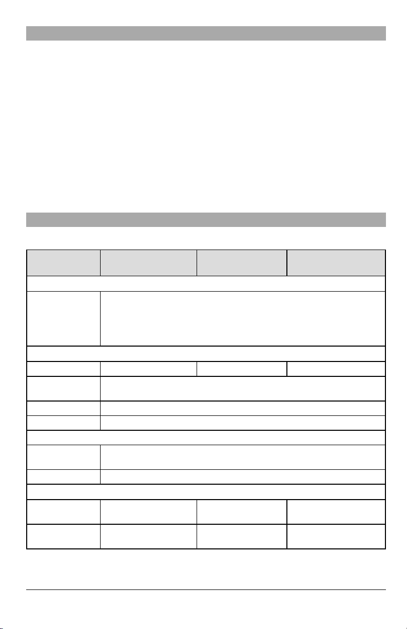
Ratings Compatibility
Table 1:Communicator Ratings
Model
3G2080(R)E/LE2080(R)
Cellularonly
Power Supply Ratings
Power is supplied from the panel’s PC-Link he ader or a PCL-4 22 mod ule in
Input Voltage
remote cabinet installations. In re mote cabinet installa tions, the PCL-422 module
located with the commu nicator is powered by either an HSM22 04 or an HSM2300.
Refer to the PCL-422 installation instructions for details.
Current Consumption
Standby Curren t 90mA 100 mA 120mA
Alarm (Transmitting)
Current
Operating Freq uency 850 MHz, 9 00MHz, 18 00MHz, 1900MHz, 2100MHz
Typical Antenna Gain 2dBi
Environmental Specifications
Operating
Temperature
-10°C to 55°C (0°C to 49°C for UL/ULC)
Humid ity 5% ~ 93% relative humidity,non -conden sing
Mechanical Specifications
Board Dime nsions
(mm)
Weight (grams) with
bracket
100 × 150 × 15 100 x 150 x 15 100 × 150 × 15
310 300 320
TL280(R)E
Internet only
10.8-12.5 VDC
400 mA
TL2803G(R)E/TL280LE(R)
Internet and Cellular
8

Table 2:Compatible Receivers and Panels
Communicator Receiver/Panel Description
l Sur-Gard System I-IPReceiver, version 1.13+
l Sur-Gard System IIReceiver, version 2.10+
3G2080(R)E
LE208 0(R)
TL28 03G(R)E
TL28 0LE(R)
TL28 0(R)E
Receiver
Panel
l Sur-Gard SG-DRL3-IP,version 2.30+ (for Sur-Gard System III Receiver)
l Sur-Gard SG-DRL4-IP version 1.20+ (for Sur-Gard System IV Receiver)
l Sur-Gard SG-DRL5-IP version 1.00+ (for Sur-Gard System 5 Receiver)
l HS2016
l HS2016-4
l HS2032
l HS2064
l HS2128
NOTE: Enter [*][8][Installer Code][900] at keypad toview the panel version number.
Pre Installation Configuration
Encryption
The communicator uses 128 Bit AES encryption. Encryption can only be enabled from the monitoring station receiver.Each
receiver (Ethernet 1 and 2, Cellular 1 and 2) can independently have encryption enabled or disabled. When encryption is
enabled, the central station will configure the device to encrypt communications the next time the communicator module
sends communication to that receiver.
NOTE: Packetswill start being encrypted only after the next event is sentto that receiver, or if the unit isrestarted.
Before leaving the installation site, the communicator TL2803(R)E / TL280LE(R) Ethernet line shall be connected via
an approved (acceptable to the local authorities) Network Interface Device (NID). Allwiringshallbe performedaccordingto the local electrical codes.
Communicator Installation Configuration
This alarm communicator shall be installed by skilled persons only (skilled person is defined as a person having the appropriate technical training and experience necessary to be aware of hazards to which that person may be exposed to in performing a task and can also take measures to minimize the risks to that person or other persons). The Communicator shall
be installed and used within an environment that provides the pollution degree max2, overvoltages category II, in non-hazardous, indoor locations only. This manual shall be used with the installation manual of the panel which is connected to the
communicator. All instructions specified within the panel manual mustbe observed.
All the local rules imposed by local electrical codes shall be observed and respected during installation.
Installing the Ethernet Cable (TL Models Only)
A Category 5 (CAT 5) Ethernet cable must be run from a source with Internet connectivity to the communicator module,
inside the panel. The communicator end of the cable must be terminated with an RJ45 plug, which will connect to the communicator’s RJ45 jack after the communicator is installed. All requirements for installation of CAT5 Ethernet cable mustbe
observed for correctoperation of the communicator,including, but not limited to, the following:
l Do NOT strip off cable sheathing more than required for proper termination.
l Do NOT kink/kno t cable.
l Do NOT crush cable with cable ties.
l Do NOT untwist CAT5 pairs mo re than ½ in. (1.2cm).
l Do NOT splice cable.
l Do NOT bend cable at right angles or make any other sharp bends.
NOTE: CAT5 specification requires that any cable bend musthave a minimum 2 in. (5 cm) bend radius. Maximum length of
CAT 5 cable is 328 ft. (100 m).
9

Inserting and Removing the SIM Card
1.
Remove the front cover of the p anel to access SIM holder.
2.
Remove power fro m the pane l and disconnect the battery a nd telephone line.
3.
On the SIM card holder push gently to slide the cover downwards to OPEN.This will unlatch the SIM card holder on
the top edge of the communicator PCB. (See Figure 3).
4.
Tilt the top of the SIM card hold er downwards to access the SIM card.
NOTE: The SIMcan be damaged by bending or scratching contacts. Use caution when handling SIMcards.
5.
Insert or remove the SIM card, noting the orientation of the n otches on the SIM card and the SIM card holder.
6.
When inserting a SIM card, insert the card in the proper orientation and gently push the SIM card holder down and
slide the holder as indicated by the arrow on SIM h older, to LOCK.
7.
Recon nect the backup battery and telephone lin e, apply AC power to panel, an d replace the panel cover.
Running the RS-232 Cable (R models only)
When installing the communicator for use with 3rd partyapplications an RS-232 cable mustbe connected between the 3rd
party device and the communicator module.
NOTE: Maximum cable length for RS-232 cable is 8 ft.(2.4 m).
Please refer to the installation manual for the 3rd party device for wiring instructions.
10
Installing Communicator in Panel
10
4
1
2
8
3
7
6
5
11
9
9
8
Installing the Communicator with HS20XX Panels
NOTE: Before installing the communicator or inserting/removing SIM, ensure that system power isoff and telephone line is
disconnected.
1.
To assemble supplied mounting bracket, perform the follo wing: (See Figure 1).
a.
Remove the 4 wh ite plastic standoffs from the bag provided with the communicator kit.
b.
Insert the 4 stand offs through the back of the mounting bracket, into the holes at each corner. Ensure the antenna
mounting tab is facing away from you.
c.
Place the bracket on a flat, solid surface. Hold the communicator component side up and orient the 4 holes on the
communicator with the 4 standoffs protruding from the bracket.Push the communicator firmly and evenly onto the
standoffs until it is securely attached to the mounting bracket.
d.
Remove the panel front cover.
e.
Remove and discard the circular knockout located in the top-right section of the panel. The knockout will be used
when connecting the anten na supplied.
f.
Connect the 5” (12.7 cm) antenna cable supplied to the radio by passing the connector through the knockou t to
the communicator b oard. Push the antenna connector firmly into the socket on the cellular radio (see Figure 3).
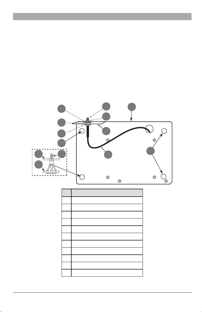
Figure 1:Communicator Mounting Bracket
Item Description
1 External Antenna Screw Thre ad
2 Brass Nut
3 Brass Washer
4 Nylon Washer (flat)
5 Anten na Mounting Tab
6 Nylon Washer with bushing (thicker flat washer)
7 Anten na Cab le
8 Mounting Holes
9 Mounting Plate
10 Commu nicator Board
11 Stand Off
11
2.
1
2
3
Install the Communicator into the p anel:
a.
Attach one end of the PC-LINK cable to the panel PCLINK_2 header on the panel (red wire goes on the righthan d pin of the panel PCLINK_2 header (see Figure 3).
b. Insert the assembled communicator into the panel.
NOTE: Ensure that the threaded antenna connection is visible through the knockout hole at the top right of the
c. Place the nylon washer with bushing (thick flat washer) onto the threaded section of the antenna cable. Insert the
d. Place the second nylon washer (flat), followed by the brass washer and the brass nut,onto the threaded section
e.
f.
g. Using light pressure (finger tight only), attach the supplied white quad band whip antenna to the threaded
panel.
threaded section through the antenna mounting knockouthole at top right of panel.
of the cable, outside the panel. Tighten the assembly by hand only (finger tight only- do not over tighten the
antenna assembly).
Locate the screw hole on the right side wall of the panel. See Figure 2 "screw". Line up the assembled com-
municator with the right side wall of the panel and, using the screw provided, secure the mounting bracket to the
panel.
Attach the other end of the PC-LINK cable to the communicator (red wire goes on the right-hand pin of the com-
municatorPC-LINK header (See Figure 3).
antenna connector attop of the panel.
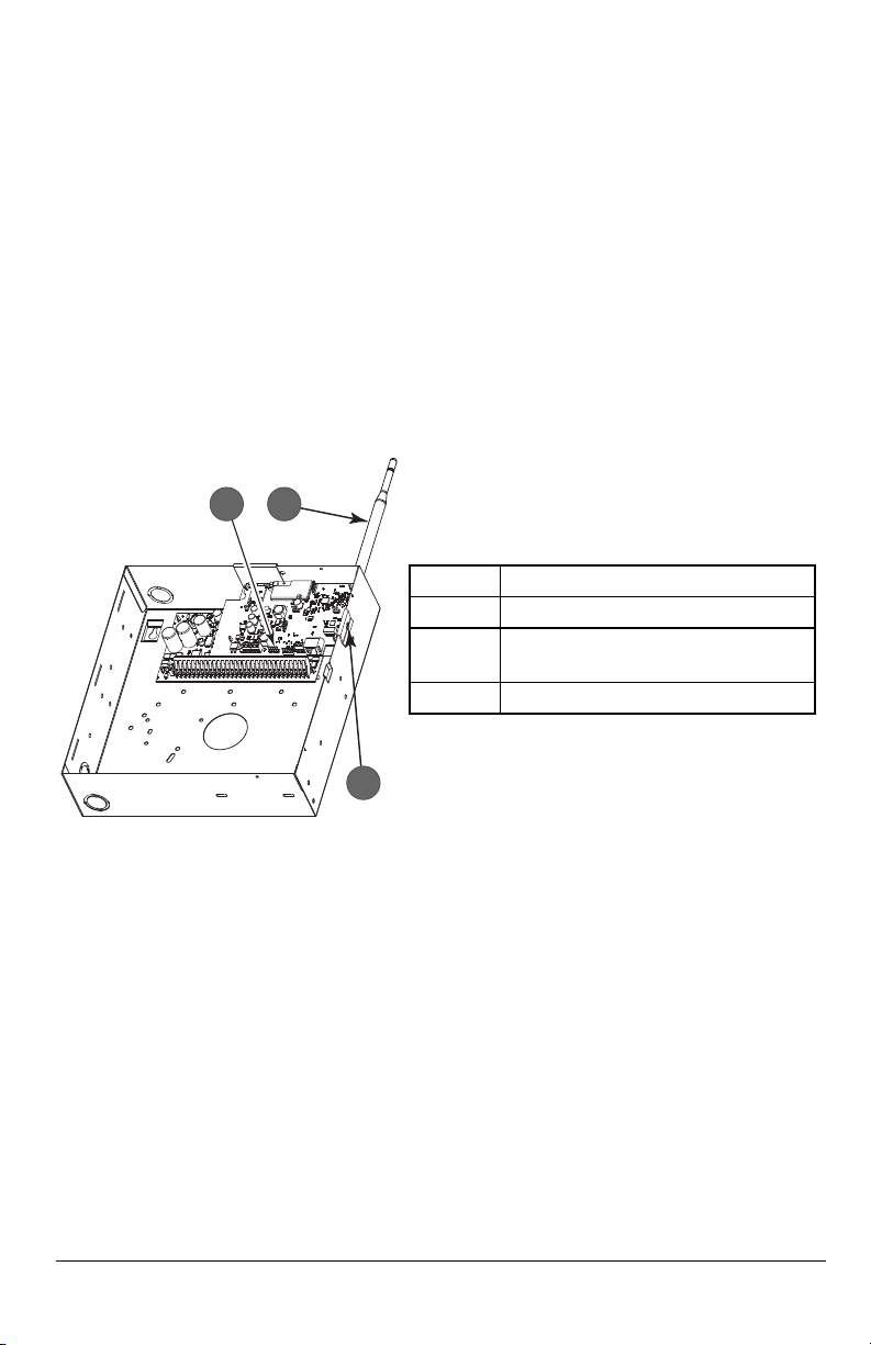
Figure 2:HS2016/2016-4/2032/2064/2128 Control Panel
Item Description
1 PC-Link Cable Connector
Quad Band Whip Antenna - Use light pressure to
2
attach antenna fingertight only
3 Screw
WARNING! - 3G2080(R)E/TL2803G(R)E/LE2080(R)/TL280LE(R) modules are power limited. Do not route any wiring
over the circuit board. Maintain at least 1in. (25.4mm) separation between circuit board and wiring.A minimum of ¼
in.(7mm) separation must be maintainedat all points between non-power limited wiring and power limited wiring.
3.
To wire the communicator to the panel, perform the following steps (See Figure 3):
a.
Disconnect both AC power and battery connections from the panel, and disconnect teleph one line.
b.
Confirm that the SIM card is inserted in the h older and locked.
4.
Install Network Cable (TL models only). Route the CAT5 Ethernet cable thro ugh back of the pa nel and plug it into the
communicator’s RJ45 jack.
5.
Install the RS-232 connections (R models only). Ifusing the communicator with a 3rd party device, wire the connections as per Table 3.
NOTE: Before leaving the premises the Ethernet communication lines must first be connected to an approved type NID
(acceptable to local authorities). All wiring shall be performed according to the local electrical codes.
12
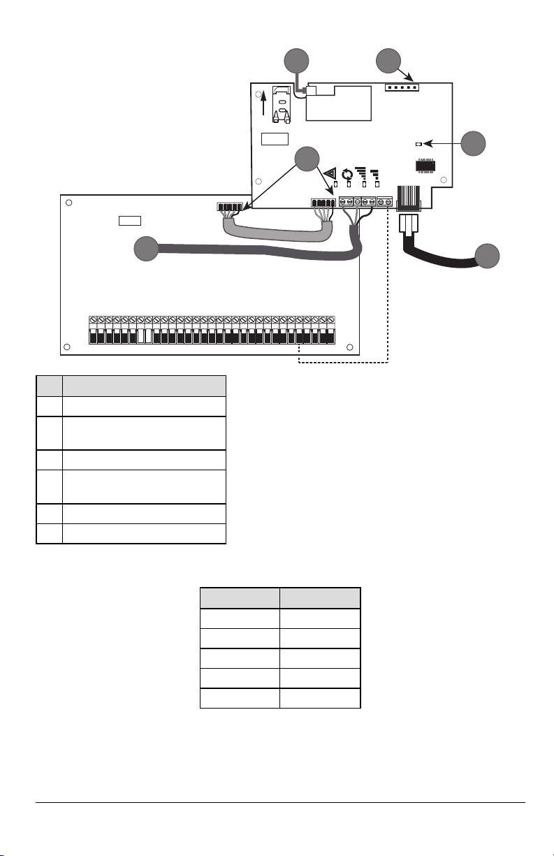
Figure 3:Communicator Wiring Diagram
AUDIO/DEFAULT
DSC
UA685
PC-LINK
PCLINK_2
COM
TL2803G(R)E
3G2080(R)E
TL280(R)E
TL280LE(R)
LE2080(R)
AC
AC
Z1 COM Z2 Z3 COM Z4 Z5 COM Z6 Z7 COM Z8
AUX+
BELL +
PGM1 PGM3
RING
T-1
HS2016/2032/2064/2128
3G/LTE Radio
UA621
L
o
c
k
1
RJ-45
GRN
YEL
TIP
R-1
BLK
RED
AUX -
BELL -
EGND
TX+
GND
TX-
RX+
RX-
SHLD
SIM
PGM2 PGM4
4
1 2
3
5
6
Item Description
1 To Externa l Antenna
AUDIO/ DEFAULT
2
Jumper pins 4 and 5 to reset
3 Ne twork Link - Yellow
From NID use only CAT5 supervised
4
maximu m cable len gth 100m (328 feet)
l +10.8V ~ +12.5VDC
l 90mA 3G2080(R)E/120mA TL2803G(R)E standby
l
l
l 100 mA TL280(R)E
l 400 mA alarm
DSC Panel minimum power requirements:
l 16.5 VAC 40 VA tran sformer
l 12 VDC 7Ah battery
5 RS-232 to third party device
6 RED Wire
Input Ratings:
Table 3:RS-232 Connections
3rd Party Device Communicator
TX (RED)* RX+
RX (GRN)* TX+
Unused RX-
Unused TX-
GND (BLK)* GND
* Wire colors based on the cable provided in the product box.
6.
Perform the following steps for initial power on of the panel with communicator installed:
a.
Recon nect the AC power, telepho ne line, a nd battery + connector to the panel.
(The communicator and panel will power up together).
90mA 3G2080(R)E/ LE2080(R)
120mA TL2803G(R)E/TL280LE(R)
13
b.
OR AND
The commu nicator’s red and yellow LEDs flash togethe r while it initializes. The red and yellow LEDs will continue
to flash until the communicator has successfully communicated to all programmed receivers.
NOTE: During radio reset,the two green LEDswill flash alternately.
NOTE: Initialization may take several minutes to complete. Do not continue to nextstep until the red and yellow LEDs have
stopped flashing. (If only the yellow LED is flashing, there is a communicator trouble and the green LEDs are not
valid for communicator placement test).Correct trouble indicated by flashes on yellow LED before continuing. See
Table 8 for troubleshooting assistance.
7.
Perform the communicator placement test below.
8.
Mount the pane l in final location indicated by placement test.
Communicator Placement Test
Cellular Communicator Models Only
To confirm that the cellular antenna location is suitable for radio operation, perform the placement test as follows:
NOTE: It might be necessary to relocate the panel or install an optional extension antenna during this procedure, if the
radio signal strength istoo low.
1.
Confirm that the yellow LED on the communicator is not flashing. A flashing yellow LED indicates trouble on the communicator. See Table 8 to troubleshoot a nd correct the cause of this trouble before continu ing to the next step.
2.
Confirm that the strength of the radio signal on the yellow LED and the 2 green LEDs on the communicator meet or
exceed the minimum signal level requirement. Minimum sig nal level: The yellow LED is OFF and the green LED 1
(furthe st from the yellow LED) is ON (not flashing) for the panel location to be acceptable. For interpretation of
receiver strength on LEDs, refer to the table “Radio SignalStrength”.
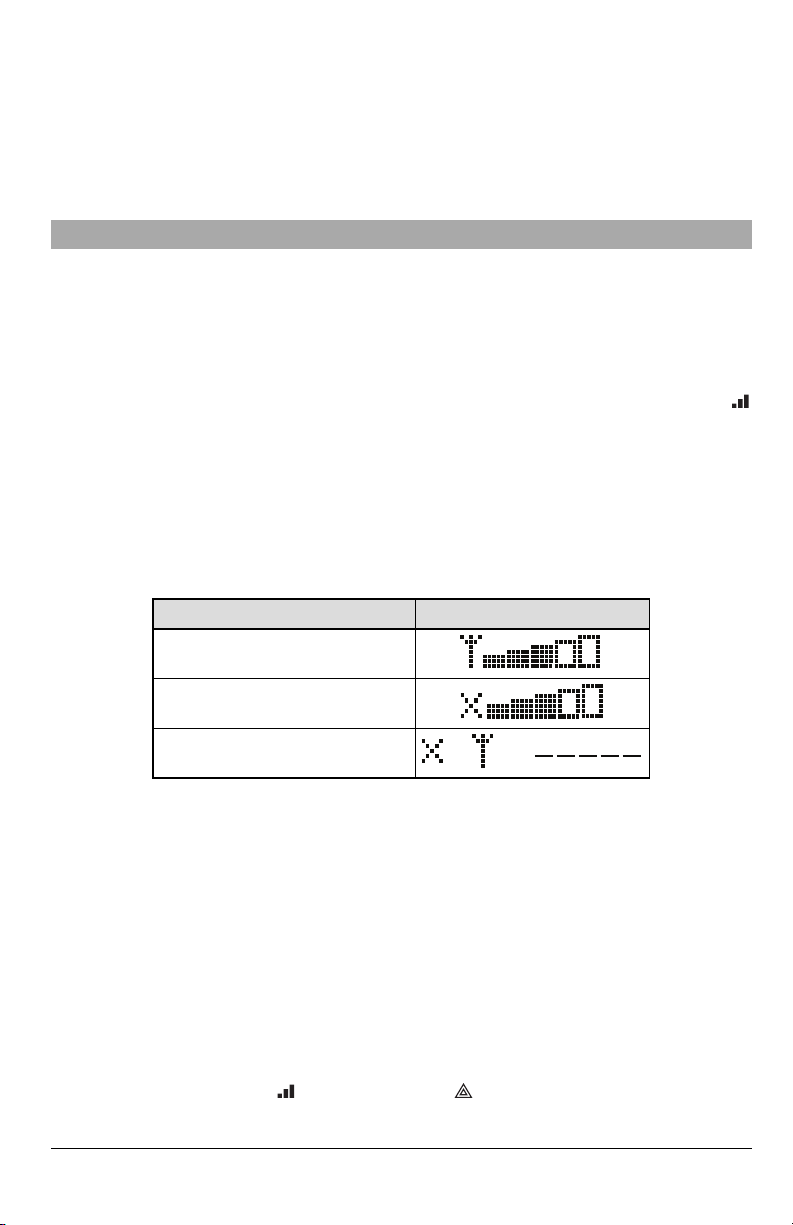
Cellular Signal Strength Display - LCD Keypad only
The cellular network signal strength can be checked on the keypad LCD screen by entering installer programming section
[850].The LCD will indicate the SIM card activation statusfollowed by up to five bars of signal strength.This display will automatically update every three seconds. For the relationship between signal strength bars, CSQ level, and signal level in
dBm, refer to “Radio SignalStrength”.
Table 4:Signal Strength Display
Description Display
SIM card active and current signal strength
SIM card inactive and current signal strength
Radio not registered
NOTE: If the required signal strength is too low with the panel in its current location, the panel must be relocated or an
external antenna is required.
Ifrequired, the following cellular extension antenna kits are available to the installer:
l GS-15ANTQ - 4.57m (15’) internal antenna exten sion kit (suitable for interio r mounting).
l GS-25ANTQ - 7.62m (25’) e xterna l antenna extension kit (suitable for interio r/exterior mounting).
l GS-50ANTQ - 15.24m(50’) external antenna extension kit (suitable for interior/exterior mounting).
Specific instructions for the installation of the extension antenna are included with the kit. Observe all the electrical safety
instructions regarding the installation of the antenna. All the wiring of the equipment shall be fully compliant with the local
rules and regulations.
3.
If required, install the antenna extension and perform the following steps to determine the best location for placement
of the a ntenna:
a.
Disconnect the white whip antenna from the panel.
b.
Attach one end of the a ntenna extension cable to the threaded antenna con nector on the panel and the other
end to the external antenna.
4.
Move the extension antenna to vario us locations while observing the two green LEDs on the panel.
a. Continue to reposition the extension antenna until it receives an acceptable (minimum one green LED ON solid)
signal strength.
NOTE: Minimum strength is: green LED 1 flashing and yellow LED off. If green LED 1 is flashing, relo-
cation should be considered.
14

b.
Mount the supplied antenna extension bracket at the location that provides the best signal strength.
c.
If necessary, relocate the pane l to improve signal strength.
5.
When final pan el/an tenna location is de termined, continue at the InitialPanel Programming section.
NOTE: If the SIMcard is not activated, placementtestwill indicate the signal strength ofthe nearestcellular tower.
NOTE: In between displaying signal strength, the signal strength LEDs will flash alternately if an inactive SIM card is used.
The flashing indicates that the module is attempting to attach to the cellular network and will only last briefly.
Initial Panel Programming
Keypad Data Display
l
Section-Toggle Options: The number is displayed when toggle is ON and the number is not displayed when toggle is
OFF. (e.g., toggle options displays: [--3--6--]. Options 3 and 6 are ON, all others are OFF). Pressing keys 1 through 8 will
alternately turn the toggle ON and OFF.
l
HEX/DecimalData: Values that are provided with two defaults, sep arated by a “/” character, use the format: hexa-
decimal followed by decimal e quivalent (e.g., default [0BF5/3061]). Hexadecimal numb ers are shown, with a ll leading
zeroes, to the full field length defined for the number.
Entering HEX values at keypad
To enter HEX values at the keypad, pressthe [*] key before entering the HEX value. (e.g.,to enter “C” at the keypad, press
[*][3])
Entering ASCII Characters at keypad
1.
Press [*] and use scroll buttons [<][>] to display “ASCIIEntry” on the LCD screen.
2.
Press [*] to select ASCIIentry mode.
3.
Use the [<] [>] scroll keys to display the desired character and pre ss [*] to save and exit ASCII.
4.
Repeat the steps above to enter another ASCII character.
HS2016/2016-4/2032/2064/2128 Initial Programming
For detailed information, refer to panel manual section ‘Alternate Communicator Set-up’. These sections must be programmed at the panel keypad. Enter [*][8] [Installer Code][Section Number]. Record any values that are modified from
their default,in the appropriate worksheetsfor the panel or communicator.
1.
In panel section [377] ‘Communication Variables’, subsection [002] ‘Communication Delays’, sub-subsection [1]
‘Communication Dela y’, program 060 (seconds).
2.
In panel section [382] ‘Communicator Option 3’ set op tion [5] ON.
NOTE: If this option is OFF,the yellow statusLED on the communicator will indicate ‘Panel Supervision Trouble’ (2 flashes)
and the unit can not be programmed via the PC-LINK cable.
Activating the Communicator with C24 Communications
Installation of the 3G2080(R)E / LE2080(R) or TL2803G(R)E / TL280LE(R) in North America requires activation with C24
Communications in order to operate. Please contact the central station (C24 Communications Master Reseller) to confirm
the required steps to activate /program the communicator.
All communicator options must be programmed via C24 Communications,except the following Ethernet options which can
also be programmed using the keypad or DLS:
l [001] Ethernet IPAddress
l [002] Ethernet IPSubnet Mask
l [003] Ethernet Gateway IPAddress
NOTE: The SIM activation with the carrier can take several hours to complete. It is recommended the activation be com-
pleted prior to arrival on the customer site to avoid possible installation delays.
Once the SIM activation is complete,the communicator will automatically connect and download itsprogramming from C24
Communications.
15
SMS Command and Control
Certain functions can be performed on the alarm panel by remote using SMS text messages. In addition, the system sends
SMS messages to confirm commands. SMS programming options are accessed through programming section [851]. The
security system only responds to SMS messages sent from designated phone numbers (programmed in section [851]>
[311]-[328]).
SMS Commands
l Stay arm the system l Deactivate comman d outpu t 1
l Away arm the system l Deactivate comman d outpu t 2
l Night arm the system l Dea ctivate comman d outpu t 3
l Disarm the system l Deactivate comman d outpu t 4
l Activate command output 1 l System status request
l Activate command output 2 l Alarm memory request
l Activate command output 3 l Zone bypass
l Activate command output 4 l Zone unbypass
SMS text messages must be formatted as follows:
<function name><space><partition #><space><access code>
(e.g.,Stay Arm partition 1 1234). Once the command is received and executed by the alarm system,a confirmation text message is received.
NOTE: For more information about SMS commands and control functions,refer to the Neo 1.1 User Manual.
Communicator Status LEDs
The communicator has four on-board LED indicators. These include one yellow trouble LED, one red network connection
status LED and two green signal strength LEDs. The LED meaning is described in this section.
Yellow Trouble LED
This yellow LED will flash to indicate a trouble on the unit. The number of flashes indicates the type of trouble, refer to the
table below for trouble conditions.
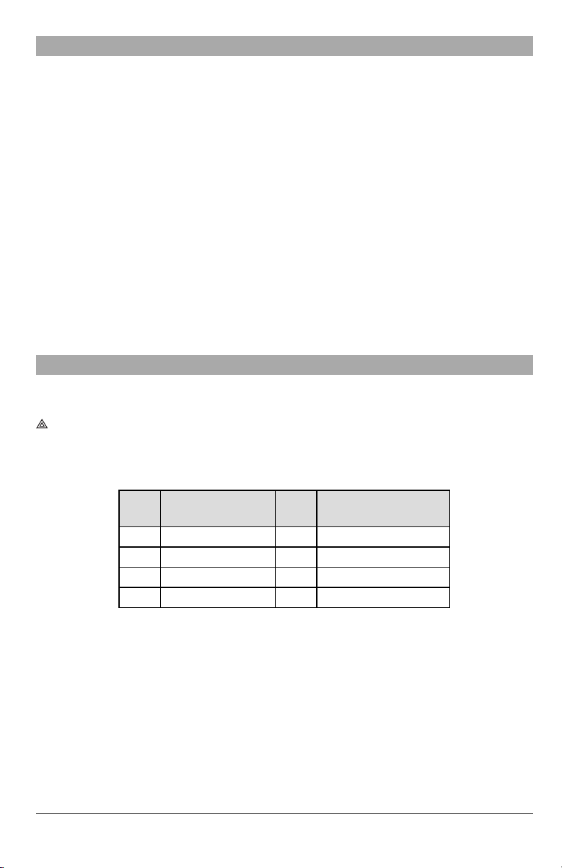
Table 5:Yellow Trouble Status LED
# of
Flashes
Trouble
# of
Flashes
Trouble
2 Panel Supervision Trouble 7 Receiver Not Available Trouble
4 Not Applicable 8 Receiver Supervision Tro uble
5 Cellular Trouble 9 FTC Trouble
6 Etherne t Trouble 12 Module Configuration Trouble
NOTE: Only the highest priority trouble (2 flashes is the highest priority trouble) is indicated. When this trouble is restored,
the nexthighest trouble is indicated, if present.This will continue until all troubles have been cleared (yellow LED is
not flashing).
The following section describes the conditions associated with each trouble:
16

Panel Supervision Trouble (2 Flashes)
This trouble occurswhen communication between the communicator module and the panel fails.Ifthe module can not communicate with the panel (e.g.,lossof power to the panel) the communicator will send the ‘Panel Absent Trouble' event message to the central station receiver. When communication returns, a ‘Panel Absent Restore' event is sent by the
communicator to the central station receiver. The reporting codes are ET0001 for trouble and ER0001 for restore. The
Panel Absent event always uses the primary receiver account code when communicating to the central station.
NOTE: The panel supervision trouble/restore are internally generated events by the communicator. Trouble is generated if
the communicator misses6 polls.Trouble isrestored on receiptof first poll from the panel.
Cellular Trouble (5 Flashes)
This trouble occursfor any of the following 4 conditions:
1.
Radio Failure: Trouble is indicated after 8 failed attemptsto communicate with the cellular radio.
2.
SIM Failure: Trouble is indicated after 10 failed attempts to communicate with the SIM.
3.
CellularNetwork Trouble: Trouble is indicated for lossof the registration to the network provider.
4.
Insufficient SignalStrength: Trouble is indicated if calculated average signal strength is too low.(Both green LEDs
are OFF).Trouble will clear when the calculated average signal strength isabove minimum (i.e.,> CSQ 5).
NOTE: If Option [851][005] Bit 8 is Off, CSQ lessthan or equal to 4 will nottrigger Cellular Trouble
Ethernet Trouble (6 Flashes)
This trouble occurs when an Ethernet link between the transmitter and the local switch or router is absent. This trouble will
also be indicated if the unit fails to get Dynamic Host Control Protocol (DHCP) settings from the DHCP server (not active if
Ethernet receiversare not programmed.
Receiver Not Available (7 Flashes)
This trouble occurs if the unit is not able to successfully initialize with any of the programmed receivers. This trouble is also
indicated if the cellular receiver APNshave not been programmed in sections [205] and [215].
Receiver Supervision Trouble (8 Flashes)
This trouble occurs when receiver supervision is enabled and communication between the communicator module and the
receiver fails. Trouble is indicated if Ethernet 1 and/or cellular 1 is supervised and does not receive a heartbeat from the
receiver or if cellular is supervised and the unit does not receive an acknowledgmentto 4 heartbeats sent to the receiver.
FTC Trouble (9 Flashes)
This trouble is indicated when the unit fails to communicate module events to the central station. Trouble is displayed after
the unit has completed all communications attempts to all programmed receivers for events generated by the communicator.
Module Configuration Trouble (12 Flashes)
This trouble is indicated when the system account code or the receiver account have not been programmed. Disabled
receivers are excluded.
Red Network Connection Status LED
TL2803G(R)E / TL280LE(R)
BLINKING:Indicatescommunication in progress.
l Once quickly for outgoing Ethernet transmission.
l Twice quickly to indicate incoming Ethernet ACK/NACK.
OFF:This is the normal stateof the red network connection statusLED. There are no network connection issues present.
ON: There is a problem with the Ethernet or the cellular network connection. LED will be ON if any of the following occur:
Ethernet cable is not connected, DHCP configuration times out, unit fails to get an IP address from the cellular network, or
Cellular connection has been reset.
(Green LED 1) (Green LED 2) and (Yellow LED) Signal Strength
NOTE: If the yellow LED isflashing, signal strength in table below is not valid.
See Table 8 for troubleshooting flashing yellowLED.
17
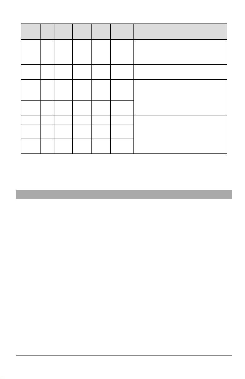
Table 6:Radio Signal Strength
Signal
CSQ
Yellow
Strength
Level
Radio
Not
Ready
Signal
2 Bars 5 - 6 OFF OFF Flashing
3 Bars 7 - 10 OFF OFF ON -99 ~ -93
4 Bars
5 Bars 14 + OFF ON ON
N/A N/A
No
1 Bar 1 - 4
11-
13
0 ON OFF OFF
Flashing
Green
LED
Alternate
Flashing
See
Note
OFF Flashing ON -91 ~ -87
Green
LED 2
LED 1
Alternate
Flashing
OFF Flashing
Signal
Level dBm
N/A
-113 or
less
-111 ~ 105
-103 ~ 101
-85 and
higher
ActionRequired
Ifthis status persists and the yellow LED shows 5
flashes,confirm that the SIMcard is active.
Confirm cellular service is active in area.
Relocate panel or install external antenna.
Check all a ntenna conn ections.
Relocate panel or install external antenna if yellow
troub le LED shows five flashes.
Location is OK. Cellular signal streng th is greater
than CSQ 7.
NOTE: The communicator will indicate cellular trouble (yellow LED = 5 flashes) if the calculated average CSQ Level is 4 or
less.
Network Activity LEDs - Red and Green ( TL2803G(R)E/TL280LE(R) only)
l
Ethernet Activity: Red LED will blink quickly once for transmit, or twice for receive.
l
CellularActivity: Green LED 2 will blink quickly once for transmit, or twice for receive
Communicator Reset/Update
Factory Defaults Reset
Restore the programming options for the communicator to the factory settings by installing a hardware jumper. Perform the
following steps to resetthe communicator:
NOTE: A jumper is required on AUDIO/DEFAULTpins 4 and 5 to resetthe hardware values.
1.
Remove panel front cover.
2.
Locate the AUDIO/DEFAULT 5 pin connector on the communicator board (see Figure 3).
3.
Apply a jumper to sho rt the h ard ware default pins 4 and 5.
4.
Remove ACand DC po wer from the panel and then reapply power to the pane l.
5.
Wait until the two green LEDs on the communicator begin flashing rapidly.
6.
Remove the jumper from the h ard ware default pins 4 and 5 (gre en LEDs will stop flashing).
7.
Replace the pan el cover.
NOTE: The communicator has now been resetto the factorydefault values.
Firmware Update
The firmware ofthe device can be updated over cellular or Ethernet (remote or local updating):
l When the firmware update b egins, a ll 4 LEDs are ON.
l During the firmware upda te process, the LEDs will cycle in a chaser pattern.
l During the firmware upda te process, the chaser pattern will briefly pause and resume again. This indicates firmware
verification check has passed, and application update will begin.
l After a successful update, the unit will a utoma tically restart.
l If the update fails, all 4 LEDs will flash ON, then OFF togethe r at 1 second intervals.
NOTE: Ifthe firmware update fails, restart the communicator by cycling power. For persistent update failures, contact tech-
nical support for assistance.
18

Communicator Troubleshooting
NOTE: For additional details:
l Refer to section [983] for troubleshooting the firmware updates
l Refer to section [984] to view the trouble status
l Refer to section [985] for troubleshooting radio initialization
Table 7:Trouble Indications
Trouble
indication
No
Indication
Yellow LED
– ON Solid
Trouble
LED – 2
Flashes
Yellow LED
– 5 Flashes
Yellow LED
– 6 Flashes
Yellow LED
– 7 Flashes
Trouble
IndicatorDigit
N/A No Power
N/A No Signal
02
Supervision
05 Cellular Trouble
06 Etherne t Trouble
07
Receiver Not
Possible
Causes
Panel
Trouble
Available
l Check the power conn ections between the pane l and the
communicator.
l Confirm PC-LINK cable is prop erly installed between
communicator and panel.
l Confirm that cellular network service is active in the area.
l Ensure the antenna is securely connected to the radio. Check
antenna stub cable is securely connected to the radio.
l If an external antenna is u sed, ensure the anten na is securely
screwed on to the antenna cable connector. Ch eck externa l
antenna for damage or open /short.
l Check section [382] toggle option[5] is ON (Altern ate
Commu nicator Enabled).
l Ensure the PC-LINK cable between the panel and commun icator
is connected properly (not reversed) and is securely in place.
l Confirm that cellular service is available and active in the a rea .
l Check all a ntenna conn ections.
l Ensure average radio signal strength is CSQ5 or h igher. (See
Table 7 ).
l Ensure the SIM card is properly inserted into the SIM card holder.
l Ensure the SIM card has been activated (could take up to 24 hrs
after install).
l If this trouble persists,relo cate the panel (and communicator) or
install an external antenna extension kit.
l Check with the ISPto confirm Internet service is active in the area.
l Ensure the Ethernet cable is securely inserted into the RJ45 jack
of the communicator and the hub/router/switch.
l Check the link light on the hub/router/switch is ON. If link light is
OFF, start the hub/router/switch.
l If DHCP is used, ensure that the unit has an assigned IP address
from the server. In Section [851] [992] verify a valid IP address is
programmed. If not, contact the network administrator.
l If proble m persists, replace the Ethernet cable and RJ45
connector.
l Ensure that the Ethernet path has Internet conne ctivity.
l If using a static IPa ddress, confirm that the gateway and subn et
mask are entered correctly.
l If the network has a firewall, ensure the network has the
programmed outgoing ports open (de fault UDP port 3060 and
port 3065).
l Ensure that all the re ceivers are programmed for DHCP o r have
the proper IP ad dress and port numbe r.
l Ensure the cellular receiver APNs have been programme d with
the access point name pro vided by the cellular provider.
l If Common Mode is used, and only o ne path is initialized while the
other path is not successful, generate a manual test transmission
over both paths or power cycle the communicator to recover the
‘Receiver Not Available’ trouble.
Trouble Possible Solution
19

Trouble
indication
Yellow LED
– 8 Flashes
Yellow LED
- 9 Flashes
Yellow LED
– 12
Flashes
All LEDs
flashin g
together
Red and
Yellow LEDs
flashin g
together
Only Green
LEDs
flashin g
Green LEDs
alternating
Trouble
IndicatorDigit
08
09 FTC Trouble
0C
N/A
N/A
N/A
N/A
Possible
Causes
Receiver
Supervision
Trouble
Module
Configura tion
Trouble
Boot Loader
Failed
Initialization
Seque nce
Hard ware
Default Jumper
Radio Reset or
Radio
Initialization
Trouble Possible Solution
l This trouble is indicated when sup ervision is e nabled and the unit
is n ot able to successfully communicate with the receiver.
l If this trouble persists,contact the central station.
l The unit has exhausted all communications attempts to all
programmed receivers for events g enerated by the
communicator.
l Restart the system, if trouble persists, contact the dealer.
l This indication appea rs when section [021] system account code
or sections [101], [11 1], [201], a nd [211 ] receiver account code
have not been programme d. Ensure that a valid accoun t code
has been entered in these sections.
l Disconnect power, then reconnect power to the commu nicator
module.
l The unit is still initializing, please wait while the unit gets its
programming and establishes a connection to all p rogrammed
receivers.
NOTE: This processmay take several minutesto complete.
l The hardware default jumper is installed an d must b e removed.
See Figure 3.
l If this status persists and the yellow LED shows 5 flashes, confirm
that the SIM card is active.
20
 Loading...