

DSC TL280 Installation Manuals

TL280(R)
Internet Alarm Communicator - International
INSTALLATION GUIDE V4.0
For installation manual visit www.dsc.com
Warning: This manual contains information on limitations regarding product use
and function and information on the limitations as to liability of the manufacturer.


WARNING: INSTALLER PLEASE READ CAREFULLY
Note to Installers
The warnings on this page contain vital information. As the only
individual in contact with system users, it is the installer’s responsibility to bring each item in this warning to the attention of all users of
this system.
System Failures
This system has been carefully designed to be as effective as possible. There are circumstances, however, involving fire, burglary, or
other types of emergencies where it may not provide protection. Any
alarm system of any type may be compromised deliberately or may
fail to operate as expected for a variety of reasons. Some, but not all,
of the reasons may be:
Access by Intruders
Intruders may enter through an unprotected access point, circumvent
a sensing device, evade detection by moving through an area of
insufficient coverage, disconnect a warning device, or interfere with
or prevent the proper operation of the system.
Component Failure
Although every effort has been made to make this system as reliable
as possible, the system may fail to function as intended due to the
failure of a component.
Compromise of Radio Frequency (Wireless) Devices
Signals may not reach the receiver under all circumstances which
could include metal objects placed on or near the radio path or deliberate jamming or other inadvertent radio signal interference.
Criminal Knowledge
This system contains security features which were known to be
effective at the time of manufacture. It is possible for persons with
criminal intent to develop techniques which reduce the effectiveness
of these features. It is important that your security system be
reviewed periodically to ensure that its features remain effective and
that it is updated or replaced if it is found that it does not provide the
protection expected.
Failure of Replaceable Batteries
This system’s wireless transmitters have been designed to provide
several years of battery life under normal conditions. The expected
battery life is a function of the device environment, usage, and type.
Ambient conditions such as high humidity, high or low temperatures,
or large temperature fluctuations may reduce the expected battery
life. While each transmitting device has a low battery monitor which
identifies when the batteries need to be replaced, this monitor may
fail to operate as expected. Regular testing and maintenance will
keep the system in good operating condition.
Inadequate Installation
A security system must be installed properly in order to provide adequate protection. Every installation should be evaluated by a security
professional to ensure that all access points and areas are covered.
Locks and latches on windows and doors must be secure and operate
as intended. Windows, doors, walls, ceilings and other building
materials must be of sufficient strength and construction to provide
the level of protection expected. A reevaluation must be done during
and after any construction activity. An evaluation by the fire and/or
police department is highly recommended if this service is available.
Inadequate Testing
Most problems that would prevent an alarm system from operating as
intended can be found by regular testing and maintenance. The complete system should be tested weekly and immediately after a breakin, an attempted break-in, a fire, a storm, an earthquake, an accident,
or any kind of construction activity inside or outside the premises.
The testing should include all sensing devices, keypads, consoles,
alarm indicating devices, and any other operational devices that are
part of the system.
Insufficient Time
There may be circumstances when the system will operate as
intended, yet the occupants will not be protected from an emergency
due to their inability to respond to the warnings in a timely manner. If
the system is remotely monitored, the response may not occur in time
to protect the occupants or their belongings.
Motion Detectors
Motion detectors can only detect motion within the designated areas
as shown in their respective installation instructions. They cannot
discriminate between intruders and intended occupants. Motion
detectors do not provide volumetric area protection. They have multiple beams of detection and motion can only be detected in unobstructed areas covered by these beams. They cannot detect motion
which occurs behind walls, ceilings, floor, closed doors, glass partitions, glass doors or windows. Any type of tampering whether intentional or unintentional such as masking, painting, or spraying of any
material on the lenses, mirrors, windows or any other part of the
detection system will impair its proper operation.
Passive infrared motion detectors operate by sensing changes in temperature. However their effectiveness can be reduced when the ambient temperature rises near or above body temperature or if there are
intentional or unintentional sources of heat in or near the detection
area. Some of these heat sources could be heaters, radiators, stoves,
barbecues, fireplaces, sunlight, steam vents, lighting and so on.
Power Failure
Control units, intrusion detectors, smoke detectors and many other
security devices require an adequate power supply for proper operation. If a device operates from batteries, it is possible for the batteries
to fail. Even if the batteries have not failed, they must be charged, in
good condition and installed correctly. If a device operates only by
AC power, any interruption, however brief, will render that device
inoperative while it does not have power. Power interruptions of any
length are often accompanied by voltage fluctuations which may
damage electronic equipment such as a security system. After a
power interruption has occurred, immediately conduct a complete
system test to ensure that the system operates as intended.
Security and Insurance
Regardless of its capabilities, an alarm system is not a substitute for
property or life insurance. An alarm system also is not a substitute
for property owners, renters, or other occupants to act prudently to
prevent or minimize the harmful effects of an emergency situation.
Smoke Detectors
Smoke detectors that are a part of this system may not properly alert
occupants of a fire for a number of reasons, some of which follow.
The smoke detectors may have been improperly installed or positioned. Smoke may not be able to reach the smoke detectors, such as
when the fire is in a chimney, walls or roofs, or on the other side of
closed doors. Smoke detectors may not detect smoke from fires on
another level of the residence or building.
Every fire is different in the amount of smoke produced and the rate
of burning. Smoke detectors cannot sense all types of fires equally
well. Smoke detectors may not provide timely warning of fires
caused by carelessness or safety hazards such as smoking in bed, violent explosions, escaping gas, improper storage of flammable materials, overloaded electrical circuits, children playing with matches, or
arson.
Even if the smoke detector operates as intended, there may be circumstances when there is insufficient warning to allow all occupants
to escape in time to avoid injury or death.
Telephone Lines
If telephone lines are used to transmit alarms, they may be out of service or busy for certain periods of time. Also an intruder may cut the
telephone line or defeat its operation by more sophisticated means
which may be difficult to detect.
Warning Devices
Warning devices such as sirens, bells, horns, or strobes may not warn
people or waken someone sleeping if there is an intervening wall or
door. If warning devices are located on a different level of the residence or premise, then it is less likely that the occupants will be
alerted or awakened. Audible warning devices may be interfered
with by other noise sources such as stereos, radios, televisions, air
conditioners, other appliances, or passing traffic. Audible warning
devices, however loud, may not be heard by a hearing-impaired person.

General Internet Alarm Communicator Installation Guide
GENERAL
IMPORTANT
This installation manual shall be used in conjunction with the control panel manual. All the safety
instructions specified within that manual shall be observed. The control panel is referenced as the
“panel” throughout this document. This installation guide provides the basic wiring, programming
and troubleshooting information. Use this guide in conjunction with the Installation Manual available online from the DSC website at www.dsc.com.
The Ethernet communicator is a fixed, wall-mounted unit, and shall be installed in the location
specified in these instructions.The equipment enclosure must be fully assembled and closed, with
all the necessary screws/tabs, and secured to a wall before operation. Internal wiring must be
routed in a manner that prevents:
• Excessive strain on wire and on terminal connections,
• Interference between power limited and non power limited wiring,
• Loosening of terminal connections, or
• Damage of conductor insulation.
WARNING: Never install this equipment during a lightning storm.
Safety Information
The installer must instruct the system user on each of the following:
• Do not attempt to service this product. Opening or removing covers may expose the user to
dangerous voltages or other risks.
• Any servicing shall be referred to service persons only.
• Use authorized accessories only with this equipment.
• Do not stay close to the equipment during device operation.
Model Information
This manual covers the following model of alarm communicator: TL280 and TL280R. References
to model TL280(R) throughout this manual applies to all specified models unless stated differently. Models ending in “R” include a built-in RS-422 interface for connecting to local third party
applications.
TL280(R): Is an Ethernet alarm communicator that sends alarm communication to Sur-Gard System I-IP, II, III (SG-DRL3IP), IV (SG-DRL4IP), and 5 (SG-DRL5IP) central station receivers
through Ethernet/Internet.
The communicator can be used as either a backup or primary communicator. The communicator
supports Internet Protocol (IP) transmission of panel and communicator events over Internet.
Panel Mounting
The following communicators are compatible with HS2016, HS2032, HS2064, and HS2128 panels:
• TL280
Features
• 128-bit AES encryption via Ethernet/Internet (NIST validation certificate number 2645).
• Ethernet LAN/WAN 10/100 BASE-T.
• Individual Internet periodic test transmission.
• Integrated call routing.
• Visual Verification (Requires Sur-Gard System 5 Receiver)
• Remote firmware upgrade capability of the communicator and panel firmware via Internet.
• Panel remote uploading/downloading support via Internet.
• PC-LINK connection.
• SIA and Contact ID (CID) formats supported.
• Trouble display LEDs.
• Supervision heartbeats sent via Internet.
1
General Internet Alarm Communicator Installation Guide
EN50131-1 Installation Requirements
For EN50131-1 compliant installations, the following programming options shall be set as
described.
Supervision Heartbeat (required for ATS4 and ATS5):
• [851][004] set to 0087h (135s heartbeat).
NOTE: The compatible receiver at ARC location shall have supervision window programmed for
1800s (ATS4) or 180s (ATS 5).
• [851][005] options 1 and 3 shall be enabled
Test transmission (required for ATS3):
•
[851]
System test options
available.
[026]
and
[027]
shall be enabled (FF) for the communication paths
• [851][124] and [125] shall be programmed with time of day for test transmission and 1440 minutes (24h) for test transmission cycle
Configuration of communication paths (all ATS classes)
• [300][001] select option 02 for auto routing (this will allow transmission of the events over all
available communication paths in the system)
• [380] enable option 5 (YES) for parallel transmission over all available communication paths
(if redundant configuration is desired)
• [382] enable option 5 (YES) this will enable Alternate communicator
• [384] enable the desired back-up configuration (receiver 2 back-up for receiver 1 or receiver 3
back-up for receiver 1).
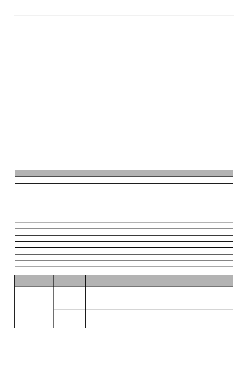
Technical Specifications, Ratings and Compatibility
Table 1: Communicator Ratings
Model TL280(R)
Power Supply Ratings
Power is supplied from the panel’s PC-Link header or a
Input Voltage
PCL-422 module in remote cabinet installations. In
remote cabinet installations, the PCL-422 module located
with the communicator is powered by either an HSM2204
or an HSM2300. Refer to the PCL-422 installation
instructions for details.
Current Consumption
Current 100mA @ 13.66V
Environmental Specifications
Operating Temperature -10°C to 55°C
Humidity 5% ~ 93% relative humidity, non-condensing
Mechanical Specifications
Board Dimensions (mm) 100 × 150 × 15
Weight (grams) with bracket 290
Table 2: Compatible Receivers, and Panels
Communicator
TL280
Receiver/
Panel
Receiver
Panel
Description
• Sur-Gard System I Receiver, version 1.13+
• Sur-Gard System II Receiver, version 2.10+
• Sur-Gard SG-DRL3-IP, version 2.30+ (for Sur-Gard System III Receiver)
• Sur-Gard SG-DRL4-IP version 1.20+ (for Sur-Gard System IV Receiver)
• Sur-Gard SG-DRL5-IP version 1.00+ (for Sur-Gard System 5 Receiver)
• HS2016
• HS2032
• HS2064
• HS2128
NOTE: Enter [*][8][Installer Code][900] at keypad to view the panel version number.
10.8-12.5 VDC
2
 Loading...