

Page 1
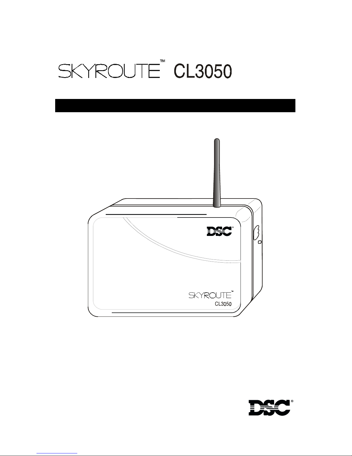
Standalone Wireless Communicator
T
Compatible with all PowerSeries keypads
Installation & Programming Guide
WARNING:
regarding product use and function and information on the limitations as to liability of the manufacturer. Read the entire manual
carefully.
This manual contains information on limitations
F
A
R
D
Page 2

Skyroute CL3050 Quick Start:
Note:
as an authorized installer to activate a Skyroute transceiver.
Enrollment is Free! If you are not already enrolled, call 1-888955-5583 in Canada or 1-888-251-7458 in the U.S. at least 24
hours before your first activation.
STEP 1 - SELECT BEST LOCATION
Connect the Skyroute transceiver to a 7 Ah battery, as
described in Section 2.1. Determine the best location for
signal strength. If adequate signal strength cannot be
found, relocation may be required.
Before you start, you must be enrolled with CONNECT 24
(See Section 2.1)
STEP 2 - CONNECT NECESSARY WIRING
Mount the Skyroute, determine the desired mode of operation and connect the appropriate control panel, zone or
Keybus wiring as detailed in Section 6.
STEP 3 - PROGRAM
(See Section 5)
(See Section 6)
If the default programming must be changed, connect a
PowerSeries keypad as shown in Section 5 and make the
desired changes.
STEP 4 - ACTIVATE
Call the Connect 24 Voice Response Unit (VRU) at the toll
free number provided with your Dealer Confirmation.
STEP 5 - TEST
Once activated, send two signals to your central station to
confirm proper operation.
YOUR SKYROUTE INSTALLATION IS NOW COMPLETE.
ALL OTHER PROGRAMMING SECTIONS IN THIS
(See Section 2.2)
(See Section 2.1)
MANUAL ARE OPTIONAL.
Page 3

Location
Test Time & Day
Additional Notes
For Your Records
CONNECT 24
Note:
Only authorized dealers can enroll a wireless system to
Dealer application forms and additional information on the Connect 24 Voice
Response Unit can be found at the Connect 24 web site.
The information required for activation is listed below. Ensure that all information
is available before calling the Connect 24 Voice Response Unit.
TM
Enrollment Information
Connect 24.
http://www.connect24.com/dealer.htm
USA 1-888-251-7458 CAN 1-888-955-5583
Profile Number ...................................................5 digits I___I___I___I___I___I
The profile number provides Central Station Receiver information.
Installer ID Number...............8-9 digits I___I___I___I___I___I___I___I___I___I
An Installer ID number was provided for each installer listed on the
Enrollment Form
sent with the
. This number can be found on the authorized
Dealer Confirmation Form.
Dealer
Installer Card
Installer PIN Number................................................ 4 digits I___I___I___I___I
Each Installer provided a 4 digit PIN number on the
you have forgotten your PIN Number contact
Connect 24.
Dealer Enrollment Form
. If
Central Station Account number ............ 2-6 digits I___I___I___I___I___I___I
This is the Account Number that will be sent to the Central Station.
NOTE:
4-digits maximum for
Skyroute MIN....................10 digits I___I___I___I___I___I___I___I___I___I___I
The Skyroute
The 10-digit MIN is located on the label affixed to your Skyroute Transmitter.
System ID Number (SID)
System ID Number
The
area
that your transmitter is installed in. When this number is programmed into
an alarm panel it is entered in
them Connect 24 Voice Response Unit, it is entered in
Contact ID
Mobile Identification Number
format.
................................5 digits I___I___I___I___I___I
informs Connect 24 and the cellular network the
HEX format.
When entering this number into
identifies the Skyroute transmitter.
home
Decimal Format.
Page 4

FCC COMPLIANCE STATEMENT
CAUTION: Changes or modifications not expressly approved by Digital Security Controls Ltd. could void your
authority to use this equipment.
This equipment generates and uses radio frequency energy and if not installed and used properly, in strict accor-
dance with the manufacturer’s instructions, may cause interference to radio and television reception. It has been type
tested and found to comply with the limits for Class B device in accordance with the specifications in Subpart “B” of
Part 15 of FCC Rules, which are designed to provide reasonable protection against such interference in any residential installation. However, there is no guarantee that interference will not occur in a particular installation. If this
equipment does cause interference to television or radio reception, which can be determined by turning the equipment off and on, the user is encouraged to try to correct the interference by one or more of the following measures:
•Re-orient the receiving antenna
•Relocate the alarm control with respect to the receiver
•Move the alarm control away from the receiver
•Connect the alarm control into a different outlet so that alarm control and receiver are on different circuits.
If necessary, the user should consult the dealer or an experienced radio/television technician for additional sugges-
tions. The user may find the following booklet prepared by the FCC helpful: “How to Identify and Resolve Radio/
Television Interference Problems”. This booklet is available from the U.S. Government Printing Office, Washington, D.C. 20402, Stock # 004-000-00345-4.
WARNING:
To satisfy FCC RF exposure requirements for mobile transmitting devices, a separation distance of 30 cm or more must be maintained
between the antenna of this device and persons during device operation.
Industry Canada COMPLIANCE STATEMENT
This Class B digital apparatus meets all requirements of the Canadian interference-causing equipment regulations.
Cet appareil numérique de la Classe B respecte toutes les exigences de règlement sur le matériel brouilleur du
Canada.
IC:160A - CL3050
The term "IC:" before the radio certification number only signifies that Industry Canada technical specifications
were met.
Limited Warranty
DSC warrants that for a period of one year from the date of purchase, the product shall be free of defects in material
and workmanship under normal use and that in fulfillment of any breach of such warranty, DSC shall, at its option,
repair or replace the defective equipment upon return of the equipment to its repair depot. This warranty applies only
to defects in materials and workmanship and not to damage incurred in shipping or handling, or damage due to
causes beyond the control of DSC, such as lightning, excessive voltage, mechanical shock, water damage or damage
arising out of abuse, alteration or improper application of the product.
The foregoing warranty shall apply only to the original purchaser, and shall be in lieu of any and all other warranties,
whether expressed or implied and of all other obligations or liabilities on the part of DSC. This warranty contains the
entire warranty. DSC neither assumes responsibility for, nor authorizes any other person purporting to act on its
behalf to modify or to change this warranty, nor assume for it any other warranty or liability concerning this product.
In no event shall DSC be liable for any direct, indirect or consequential damages, loss of anticipated profits, loss of
time or any other losses incurred by the purchaser in connection with the purchase, installation or operation or
failure of this product.
Important!
Test results are only valid at the time of testing. Results may vary with but are not limited to environmental
and structural changes. Electrical equipment operating in the immediate area may cause interference.
Skyroute, PowerSeries, Connect 24 are trademarks of DSC
Page 5

Table of Contents
Section 1: Introduction ...................................................................... 1
1.1
1.2
Specifications.......................................................................................................2
Unpacking ...........................................................................................................2
Section 2: Installation, Testing & Factory Defaults .......................... 3
2.1
2.2
2.3
Installation...........................................................................................................3
Testing .................................................................................................................4
Resetting to Factory Defaults................................................................................4
Section 3: Controls & Indicators........................................................ 5
3.1
3.2
3.3
LED Indicators ......................................................................................................5
Enroll Button........................................................................................................6
Terminal Connections...........................................................................................6
Section 4: Power up Sequence.......................................................... 7
Section 5: System Programming ....................................................... 8
Section 6: Programming Descriptions .............................................. 9
[01]
[02]
[03]
Zone 1-2 Definitions ............................................................................................9
Zone 3-8 Definitions ............................................................................................9
Zone 1-2 Loop Response......................................................................................9
[10]
[11]
[12]
[13]
[15]
[16]
[17]
[18]
[20]
[21]
[22]
[23]
Skyroute CL3050 Mode of Operation...................................................................9
Skyroute CL3050 Configuration Options 1 .........................................................10
Skyroute CL3050 Configuration Options 2 .........................................................11
Skyroute CL3050 Trouble Output Mask ..............................................................11
System Time ......................................................................................................13
System Day........................................................................................................13
Test Transmission Time .......................................................................................13
Test Transmission Day.........................................................................................13
Transmission Options .........................................................................................13
System Event Communication Options...............................................................15
Input Supply Fail Tx Delay...................................................................................15
Generic Zone Reporting Timer............................................................................15
Section 7: Programming Worksheets ............................................. 16
Glossary of Terms............................................................................. 19
Appendix A ...................................................................................... 20
i
Page 6

ii
Page 7
1 Introduction
1 Introduction
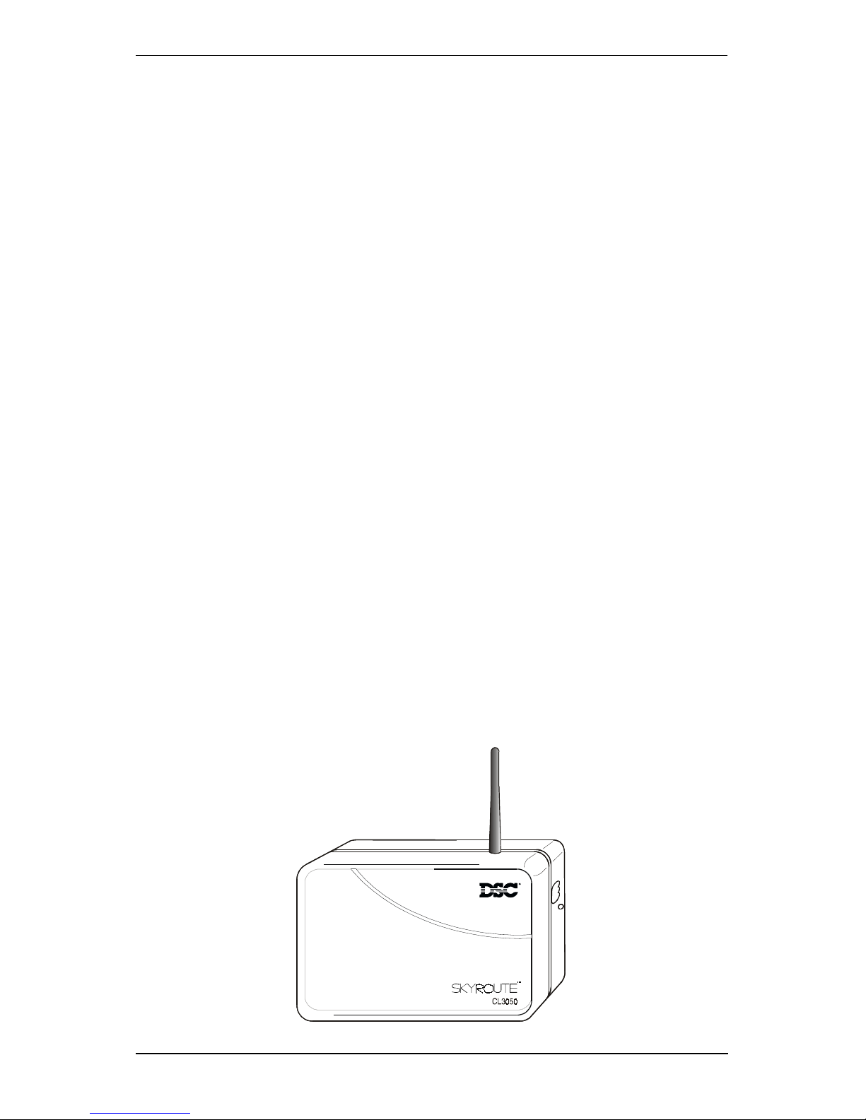
The Skyroute CL3050 is a standalone wireless communicator that sends alarm system information to
The Skyroute CL3050 automatically configures itself on power up to one of three operational modes or; if it is connected to a keypad, in the programming mode. The Skyroute
CL3050 is pre programmed with the most commonly used settings for quick installation. If
required the default options can be custom programmed.
Mode 1: Bell Follower
Connect 24
If the Skyroute CL3050 does not detect a keypad or PC5108 expander card during the first 15 seconds of power up, then mode 1 or 2 can be selected by pressing the enroll button. The red LED indicates Mode 1 and the yellow LED indicates
mode 2. In Mode 1, the Skyroute CL3050 monitors the
trol panel. The system identifies the Bell Output cadence and transmits the corresponding Fire or Burglar alarm reporting code to
Refer to the appropriate
. Connect 24 then forwards this information to the central station.
Bell Output
Connect 24
control panel Installation Manual.
.
of the con-
Mode 2: 2-Zone Panel
If Mode 2 is selected during power up the system will configure itself for 2 zone,
stand alone operation with normally closed loops.
Mode 3: 8-Zone Panel
If the Skyroute CL3050 detects a PC5108 expander card on power up it will automatically configure itself for 8-zone standalone operation with normally closed
loops.
Programming Mode
If the Skyroute CL3050 detects a keypad on power up it will go into the programming mode. Programming mode allows the installer to custom program system
options. Refer to Section 5, Programming Descriptions; and Section 6, Programming Worksheets for programming options and default settings.
Note:
Figure 1
The only method of entering the Programming Mode is to power-down the unit,
connect a PowerSeries keypad to the Keybus terminals, then reapply power to
the Skyroute CL3050.
1
Page 8

Skyroute CL3050 Standalone Wireless Communicator
1.1 Specifications
• Power Supply
Voltage...................................................................................... 9-12 V
Current.........................................................................................500 mA (Max)
Low DC Trouble ......................................................................................8.8 V
Low DC Restore......................................................................................9.0 V
Low AC Trouble ...................................................................................... 7.5 V
Low AC Restore...................................................................................... 8.0 V
• Current Drain
Standby ................................................................................................. 100 mA
Receiving ............................................................................................... 150 mA
Transmitting........................................................................................... 850 mA
• RF Power Output .......................................................................................... 600 mW
• Battery
Charging Voltage..................................................................................6.87 V
Low Battery Restore..............................................................................5.87 V
Low Battery Trouble.............................................................................. 5.72 V
Critical Shutdown ...................................................................................5.0 V
• Operating Modes
Bell Follower
2-24Hr Zones
8-24Hr zones (with PC5108)
• Event Buffer (communications)............................................. 32 Events (not viewable)
• Dimensions...................................................................................5 1/8” x 7 3/4” x 2”
• Weight ............................................................................................... 0.5 lbs. (0.2Kg)
• EEPROM Memory
• Programmable by all PowerSeries Keypads
PC5508/KP5508Z ................................................................. 8 Zone LED keypad
PC5516Z/KP5516Z ............................................................. 16 Zone LED keypad
PC5532Z/KP5532Z ............................................................. 32 Zone LED keypad
LCD5500Z/KPL5500Z ................................ Programmable Message LCD Keypad
LCD5501Z/KP5501Z ................................................. Fixed Message LCD Keypad
AC
or V
DC
DC
DC
AC
AC
DC
DC
DC
DC
1.2 Unpacking
Verify that the following items have been included.
1 Skyroute CL3050 (rechargeable battery included)
1 Installation & Programming Guide
1 Antenna
4 Mounting screws
45.6 k
Remove antenna from protective bubble pack and install in unit.
Caution:
Caution:
resistors
Ω
Install antenna before connecting battery or power leads to this unit.
Transmission without an antenna can cause permanent damage.
When removing cover of this unit
electrical devices and components. Electrostatic discharge (ESD) can
permanently damage this unit or reduce the reliability and life expectancy of components.
DO NOT
touch or handle exposed
2
Page 9
2 Installation, Testing & Factory Defaults
2 Installation, Testing & Factory Defaults
2.1 Installation
1 Determine The Operating mode required (see section [03])
The operating mode (modes 1, 2, or 3) will determine how the unit is to be wired
up. Refer to section 6,
options and for programming defaults.
2 Determine the Mounting Location
Programming Descriptions, section [10]
for available
Select a mounting location
should be positioned so that it is at least 30 cm. away from physical contact with
any person.
Do Not exceed the following recommendations for wire run distances
Note:
• Keybus and zone wiring should be run using minimum 22 gauge quad
(0.5mm). Two pair twisted is preferred.
• a keypad, PC5108, or zone wiring can not exceed 1,000'/305m (in wire
length) from the Skyroute CL3050.
• Shielded wire is not necessary unless wires are run in an area that may present
excessive RF noise or interference.
•Refer to section 6,
ing details.
Note:
3
Checking Signal Strength
• Remove front cover
• Connect Battery to the RED and BLK flying leads.
• Connect AC Power source or 12 V
• Allow unit to power up
Note:
• When the green LED stops flashing, press and release the enroll button.
• Ensure that Radio Signal Strength Indication (RSSI) is greater than the mini-
Generally, the higher the location and the closer that the Skyroute
CL3050 is to an outside wall, the better the signal strength will be.
The unit does not need to be enrolled with
nal strength.
mum acceptable level as indicated below. If the signal level is not acceptable, reposition and retest the Skyroute CL3050 until an acceptable signal
strength is found.
Programming Descriptions, section [10]
in a dry, protected area. The mounting location
for zone wir-
DC
to RED & BLK terminals.
Connect 24
to check sig-
Red LED Yellow LED Green LED Signal Strength
On
On
On
On
On
Flash
*Minimum recommended signal strength for enrollment
4 Route Wiring to Mounting Location
Route wiring from the hardwired zones or control panel as required.
Note:
Route wiring through conduit to a junction box if possible. Mount the
Skyroute Panel.
On
On
On
Flash
Off
Off
On
Flash
Off
Off
Off
Off
3
>87%
69-87%
*
52-68%
34-51%
16-33%
0-15%
Page 10

Skyroute CL3050 Standalone Wireless Communicator
5 Mount Unit
• Remove the front cover if required
• Disconnect flying leads from battery and power leads from the RED and BLK
terminals (if connected).
• Remove two screws securing battery clamp. Remove battery
• Mount backplate of unit to wall or over electrical junction box using the
four screws provided.
6 Enroll Unit
2.2
Note: DO NOT
to the terminal strip until all other wiring connections are completed.
• Route wiring through the access holes provided and connect to terminal
strip.
• power up unit by connecting battery and power source.
Call Connect 24 and Enroll the Skyroute CL3050. Refer to
information and a list of information required to complete the enrollment with
the Connect 24 Voice Response Unit.
connect the battery to the flying leads and AC or DC power
page (ii)
for contact
Te s t i n g
Program Mode:
mode. Follow the steps outlined in
record the program settings in
Test Transmission -
send a test transmission to the central station via
Button
Mode 1:
Burglar and Fire Zone violation. Verify that the Skyroute CL3050 transmits the
events to the central station.
in
Disable the telephone line connected to the control panel. Simulate
If you have wired the unit to power up in the programming
Section 6, Programming Descriptions
Section 7, Programming Worksheets.
Pressing and holding the enroll button for 2 seconds will
Connect 24.
Section 3, Controls and indicators
for test transmission details.
Refer to
Enrol
and
2.3
Mode 2 & 3:
the settings outlined in
Skyroute CL3050 transmits the events to the central station.
Simulate Faults, Tampers, and Zone violations in accordance with
Sections 6, Programming Descriptions
. Verify that the
Resetting to Factory Defaults
Note:
• Remove Power from the Skyroute CL3050; disconnect battery and control
• Disconnect all wiring from the YEL and GRN terminals.
• Connect a jumper wire between the YEL and GRN terminals.
• Apply power to the system.
Note:
• Remove power from the system.
Note:
• Reconnect all original wiring and reapply power to the system.
• Test System - Refer to
Resetting to factory defaults is required to change mode of operation.
panel if applicable (mode 1).
When the hardware default has been completed; the yellow, green
and red LEDs will flash on and off continuously.
To resume communications with
must be set to ON. To do this; the system must be powered up in programming mode. Refer to
Section 2.2
Connect 24, Section [11], Option 6
Section 5 System Programming.
4
Page 11
3 Controls and Indicators
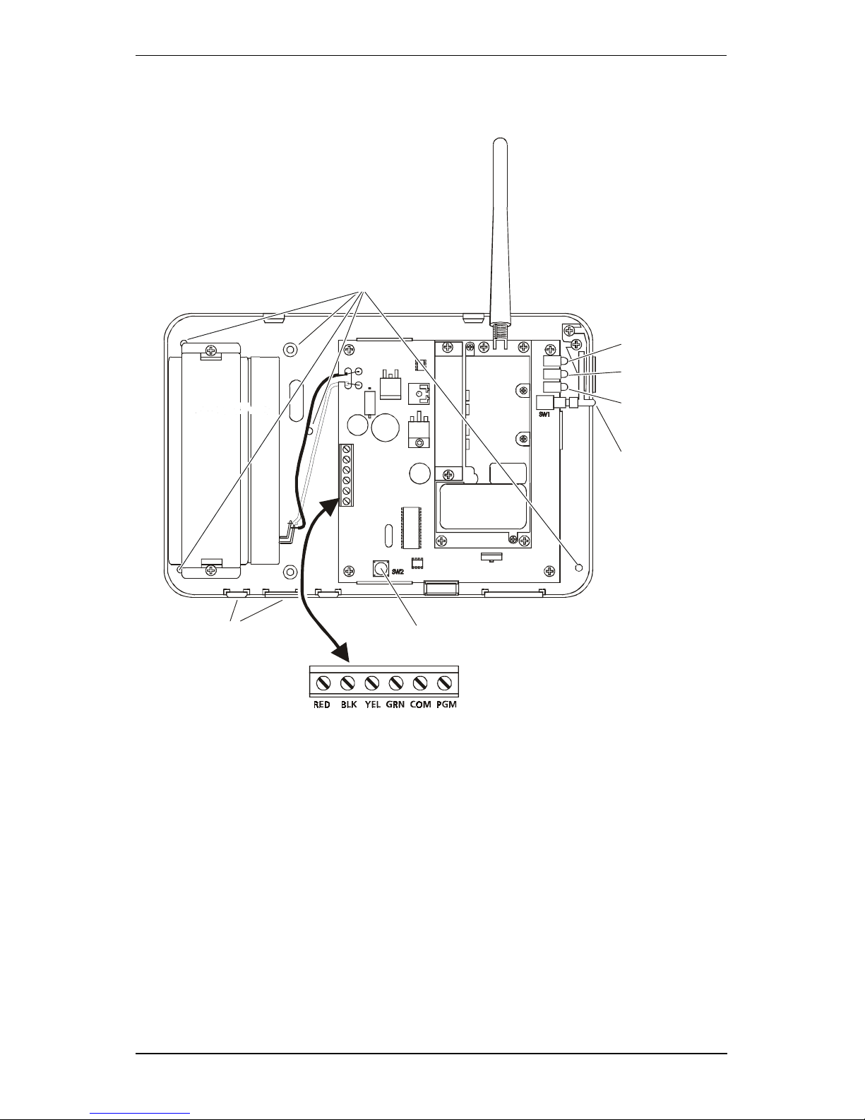
Figure 2
Antenna
Mounting Holes
3 Controls and Indicators
Green LED
Yell ow LE D
Battery (6 V )
Wire Access
DC
Ta mp e r S w itc h
3.1 LED Indicators (see figure 2)
Yellow LED
During normal operation, the yellow LED will indicate the system status with a
series of flashes as indicated below.
Red LED
Enroll Button
No. of
Flashes Indication
1
2
3
4
5
6
7
8
9
No trouble conditions present
Low battery
Input supply failure
Not enrolled at
No service available*
Radio failure
PC5108 failure
Failure to communicate
Zone tamper/fault trouble
Connect 24
5
Page 12

Skyroute CL3050 Standalone Wireless Communicator
Note:
Multiple trouble conditions are displayed (flashed) in sequence.
Red LED
The red LED will flash to provide event transmission status for the following
events:
1 Flash
1 Flash
2 Flashes
Enroll button held down for 2 seconds
Event transmitted to cellular network
Event acknowledged by
Green LED
The green LED will light continuously if the (RSSI) signal is acceptable. If signal
strength is not acceptable the LED will turn OFF. Detailed information on signal
strength can be accessed by momentarily pressing and releasing the enroll
button. The green, yellow and red LEDs will light to indicate the range of signal
strength. Refer to
Section 2 Step 3.
3.2 Enroll Button (see figure 2)
The Skyroute CL3050 Enroll button is located on the outside of the plastic housing directly below the status LEDs. The enroll button performs three functions.
• Pressing this button during the first 15 seconds of power up will toggle
between Mode 1 and Mode 2 to enable mode selection.
• Pressing and releasing this button momentarily at any time after the power
up sequence will display the detailed RSSI status indicated above.
• Holding this button down for a period of 2 seconds continuously will cause
the Skyroute CL3050 to send a test transmission to
debounce will be indicated to the user by the red LED flashing once.
3.3 Terminal Connections (see figure 2)
Connect 24
Connect 24
.
, this long
RED 9-12V
Note:
BLK 9-12V
YEL
Mode 1 Mode 2 Mode 3 -
using a PC5108 zone expander or PowerSeries keypad.
GRN
Mode 1 Mode 2 Mode 3 -
using a PC5108 zone expander or PowerSeries keypad.
COM
Mode 1 -
Input on the YEL terminal, the TLM trouble input on the GRN terminal
and the Trouble Output on the PGM terminal.
Mode 2 -
(YEL) and zone 2 (GRN).
Mode 3 -
Trouble Output
DC
Positive Input or 9-12V
is required for programming or for operation with a
12V
DC
AC
PC5108 zone expander. Mode 1 and Mode 2 may be operated
with an AC Supply.
DC
Ground or 9-12V
AC
The YEL terminal functions as the Bell input.
This terminal functions as the zone 1 input.
This terminal connects to the YEL Keybus terminal when
The GRN terminal functions as the TLM Trouble input.
This terminal functions as the zone 2 input.
This terminal connects to the GRN Keybus terminal when
This terminal functions as the common terminal for the Bell
This terminal functions as the common terminal for zone 1
This terminal functions as the common terminal for the
6
Page 13
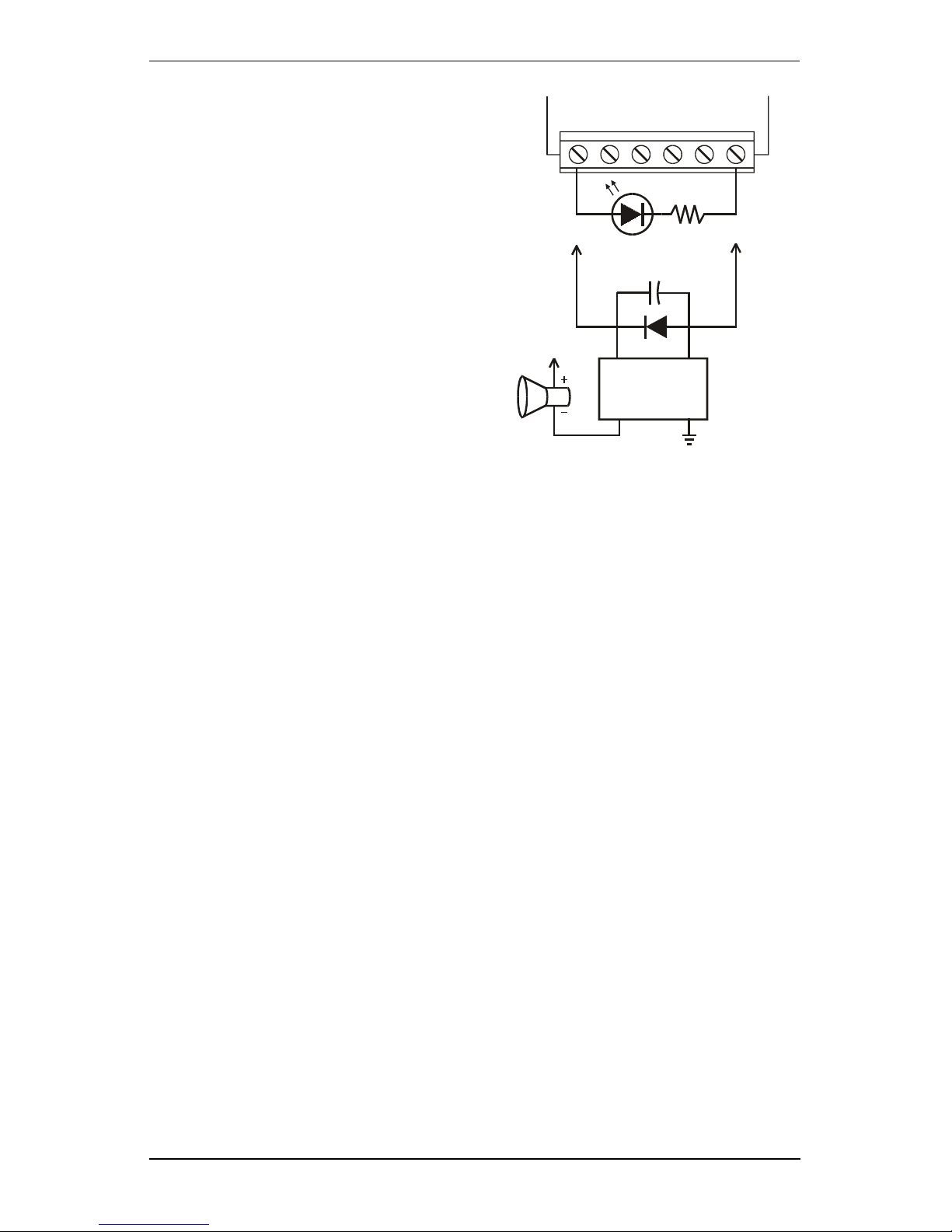
4 Power up Sequence
PGM - The PGM output is
dedicated for Skyroute
CL3050 trouble indications. If a control panel is
not monitoring the Skyroute CL3050, an LED or a
buzzer can be connected
between this terminal and
the RED terminal for trouble
indication. The PGM terminal switches low from an
open-collector state. Connect to the control panel
using a Single EOL configuration as shown
The PGM output can
Note:
sink 50 mA (maximum).
4 Power up Sequence
On first-time power up, the Skyroute CL3050 will generate a random test transmission time and random day of the week to send it. The installer can then
change this information if required.
LED Output with
current limiting
resistor
Optional relay
driver output
To External
Supply
Skyroute CL3050
RED BLK YEL GRN COM PGM
LED 560
+ Coil -
Ω
Relay
NC Com
During power up, the Skyroute CL3050 will look for a keypad on the Keybus, if
one is found, it will go into programming mode. If no keypad is found, it will
look for a PC5108 zone expander module. If a zone expander is found, it will
automatically configure itself for mode 3. If no Keybus modules are present, the
Skyroute CL3050 will power up in mode 1. During the first 15 seconds of power
up, any zone scanning will be shunted. During this time the installer can momentarily press the enroll button on the Skyroute CL3050 to toggle between mode 1
and mode 2. Upon power up the green LED will be flashing on and off. This will
indicate to the installer that he/she can change the mode to 1 or 2. The red LED
will indicate mode 1 and the yellow LED will indicate mode 2. If neither red or yellow LED is lit, then the Skyroute CL3050 has detected a PC5108 module, the
mode cannot be changed by pressing the enroll button if a PC5108 module is
connected to the Skyroute CL3050.
keypad
If a
is detected on Keybus, the green LED will stop flashing, and the red
LED will begin flashing to indicate that programming mode is active.
7
Page 14
Skyroute CL3050 Standalone Wireless Communicator
5 System Programming
The Skyroute CL3050 is programmed using a PowerSeries keypad. Refer to
Section 1.1 Specifications.
Note:
Power down the Skyroute CL3050 when connecting or removing
other Keybus modules from the system
the Skyroute CL3050 is con-
. If
nected to a control panel (mode 1), the control panel must also be
powered down
.
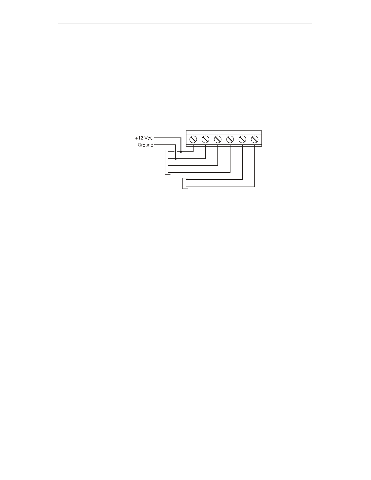
1. Connect keypad Keybus connections to the RED, BLK, YEL and GRN terminals of the Skyroute CL3050.
RED BLK YEL GRN COM PGM
To Keybus
Connections
on Keypad
Not Connected
2. Connect a +12VDC supply across the RED and BLK terminals.
Upon detecting the keypad on power up, the Skyroute CL3050 will begin
driving Keybus and will blank the keypad with all LEDs and icons off.
3. Press the star [*] key to gain access to the programming section.
Programming is done with a 2-digit section entry. When programming is
complete, power down the Skyroute CL3050 and remove the keypad.
8
Page 15
6 Programming Descriptions
6 Programming Descriptions
[01] Zone 1, 2 Definitions
When the Skyroute CL3050 is in Mode 2 or 3, there are 14 options that can be
programmed as zone types. All of the zone types with the exception of 00 (null
zone) and 13 (TLM monitor) are straightforward. Since all the zones are 24-hour
type zones, selecting any listed zone type will simply select which identifier
should be used for reporting the alarm. Programming a zone as 00 (null zone)
will disable the zone input on the Skyroute CL3050 or PC5108 hardware. Programming any zone as type 13 will disable all communications unless that zone
input is closed (short condition).
Note:
Do
program more than 1 TLM zone type on the Skyroute
NOT
CL3050.
Default
- [01] zones 1 & 2
[02] Zone 3 - 8 Definitions
This allows programming of the six additional zone definitions when operating in
mode 3 with a PC5108 zone expander. See section [01] for details
Default
- [01] zones 3 - 8
[03] Zone 1, 2 Loop Response
This entry determines how quickly a zone will respond to changes in state.
This does not affect zones on a PC5108 zone expander card.
Note:
Default -
05 (0.5 seconds) 01-FF Hex x 0.1 seconds.
Modes 2, 3
Mode 3
Modes 2
[10] Skyroute CL3050 Mode of Operation
[01] Mode 1 - Bell Follower Operation
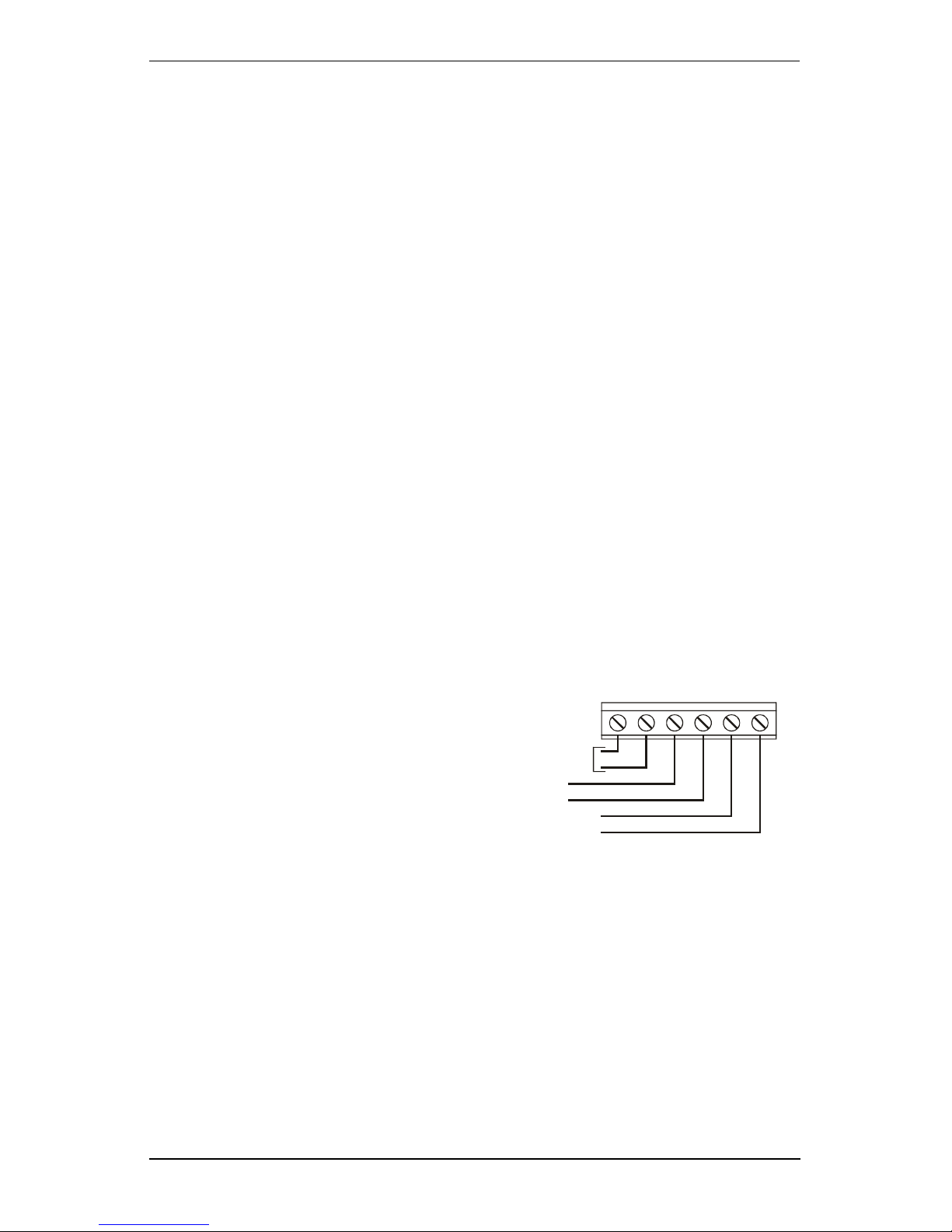
In this mode, the YEL terminal is connected to the bell output of a control
panel. The Skyroute CL3050 monitors the output for burglary and fire
cadences and transmits the appropriate events. For any type of pulsed
cadence, the Skyroute CL3050 will
send a generic Fire event, for any
steady bell the Skyroute CL3050 will
send a generic Burglary event. The GRN terminal is a trouble input which can be
connected to a system output to alert the Skyroute CL3050 of a system TLM
fault. This will enables the Skyroute CL3050 to be used as a back-up communicator only.
If not used, this input must to connected to COM
cadence will be determined as follows:
• Bell must be on for longer then 300mS to be considered a "pulse"
• Bell must be on for 3 seconds continuous to be considered "steady"
• Bell must be off for 3 seconds continuous to be considered "silenced"
• Bell must pulse on and off 3 times to be considered "pulsed", 3rd off-time
will trigger event
Input Voltage
9-12V or V
Bell Input
TLM Input
System Common
Trouble Output
RED BLK YEL GRN COM PGM
AC DC
. The bell
Bell Report Code Group
Pulsed
Steady
FA98
BA98
9
Fire
Burglary
Page 16
Skyroute CL3050 Standalone Wireless Communicator
[02] Mode 2 - (2) 24-Hour Zones
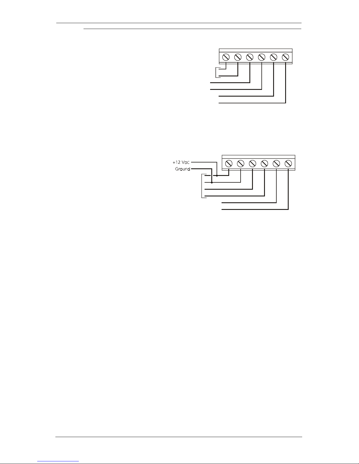
In this mode, both the YEL and
GRN terminals on the Skyroute
CL3050 will be used as zone
inputs. These zones will support
the DSC standard EOL configuration and loop response. Programming sections will allow the
installer to change the default
zone types and attributes. The
Skyroute CL3050 will continuously monitor these zones and transmit any alarms that occur to the central station.
[03] Mode 3 - (8) 24-Hour Zones
In this mode, the Skyroute
CL3050 is connected to a
PC5108 zone expander using
the corresponding RED, BLK,
YEL and GRN terminals. The
Skyroute CL3050 will drive the
Keybus to communicate with
DC
the PC5108. A +12V
supply connected to the RED and
BLK terminals is required
when using this mode. The Programming sections will allow the installer to
change the default zone types and attributes. The Skyroute CL3050 will continuously monitor these zones and transmit any alarms that occur to the central
station.
Input Voltage
9-12V or V
AC DC
Zone 1 Input
Zone 2 Input
Zone Common
Trouble Output
To Keybus
Connections
on PC5108
System Common
Trouble Output
RED BLK YEL GRN COM PGM
RED BLK YEL GRN COM PGM
This configuration can not be used with an AC supply.
Note:
Jumpers on the PC5108 must be set as follows:
Note:
J1
Default -
ON
J2
OFF
J3
ON
[01 -03] dependant on start up configuration
J4
J5
J6
OFF
OFF
ON
[11] Skyroute CL3050 Configuration Options 1
Option 1 - A Channel Selected/ B Channel Selected.
This Option determines whether cellular channel
Canada, Channel B is used (Default). In the USA refer to the SID list for the channel of the cellular service provider in your area.
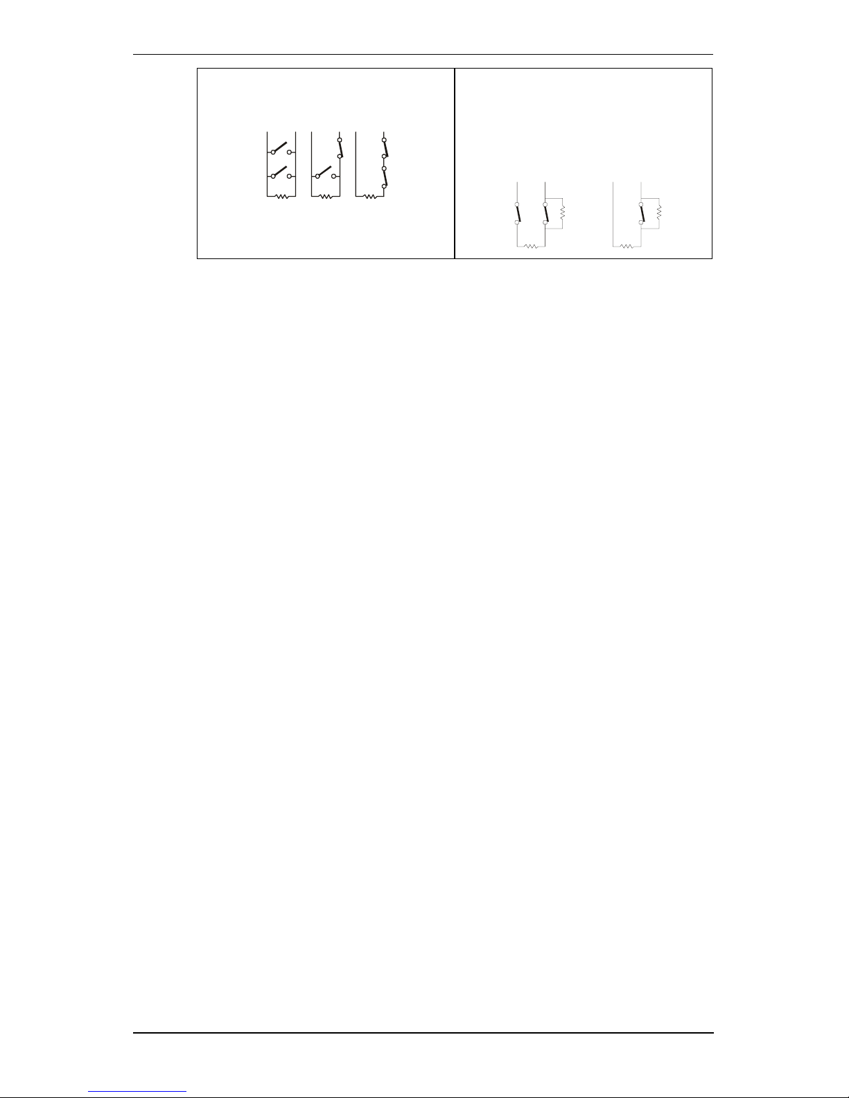
Option 2 - Normally Closed Loops/ End-of-line Resistors
Normally Closed Loops can be wired as shown. Multiple
Normally Closed contacts can be wired in series. For Double
or Single EOL resistors this option must be set to
Default -
Normally Closed (N/C) Loops.
Option 3 - Double EOL Resistors/Single EOL Resistors
This option selects Double EOL resistors (ON) or Single EOL resistors (OFF) wired
as indicated
“B”
Default -
OFF
or channel
Channel B
.
“A”
is used
All Modes
. In
Mode 2, 3
Mode 2, 3
10
Page 17
6 Programming Descriptions
Single EOL resistors
allows the use
of N/C and/or Normally Open contacts.
C Zx
C Zx
C Zx
Double EOL resistors
zone to be monitored for fault,
tamper, secure and violated conditions. Only Normally Closed contacts
allows the
can be used in this configuration
Ω
5.6K
Note:
Option 2 must be set to
Default -
5.6K
OFF
Ω
5.6K
Ω
OFF
to enable these options.
Tam pe r
Contact
5.6K
Ω
Option 4 - Test Once a Day Enabled/Disabled
Allows transmission test daily.
Default -
Disabled.
Option 5 - Test Once a Week Enabled/Disabled
C Z x
5.6K
Ω
C Z x
All Modes
All Modes
5.6K
5.6K
Ω
Allows transmission test weekly.
Note:
This option will be overridden If option 4 is set for daily test transmissions.
Default -
Option 6 - Enrolled with Connect 24 /Not Enrolled
Enabled.
All Modes
This option is set automatically during the enrollment procedure with
Connect 24. IF the Skyroute CL3050 is reset to the default settings this option
must be set to ON for the Skyroute CL3050 to resume communications.
Default -
Not Enrolled.
Ω
Options 7, 8 - System Use
Caution:
Do
change these settings unless it is requested by DSC
NOT
technical support personnel.
Default -
OFF.
[12] Skyroute CL3050 Configuration Options 2
Option 1 - Swinger Shutdown Enabled/Disabled
This option limits the number of alarm events transmitted per zone to 8 until the
counter has been reset (counter automatically resets at midnight), then event
transmissions will resume.
Note:
Tampers and Faults will be counted unless they are disabled in
Default -
Enabled
section [20].
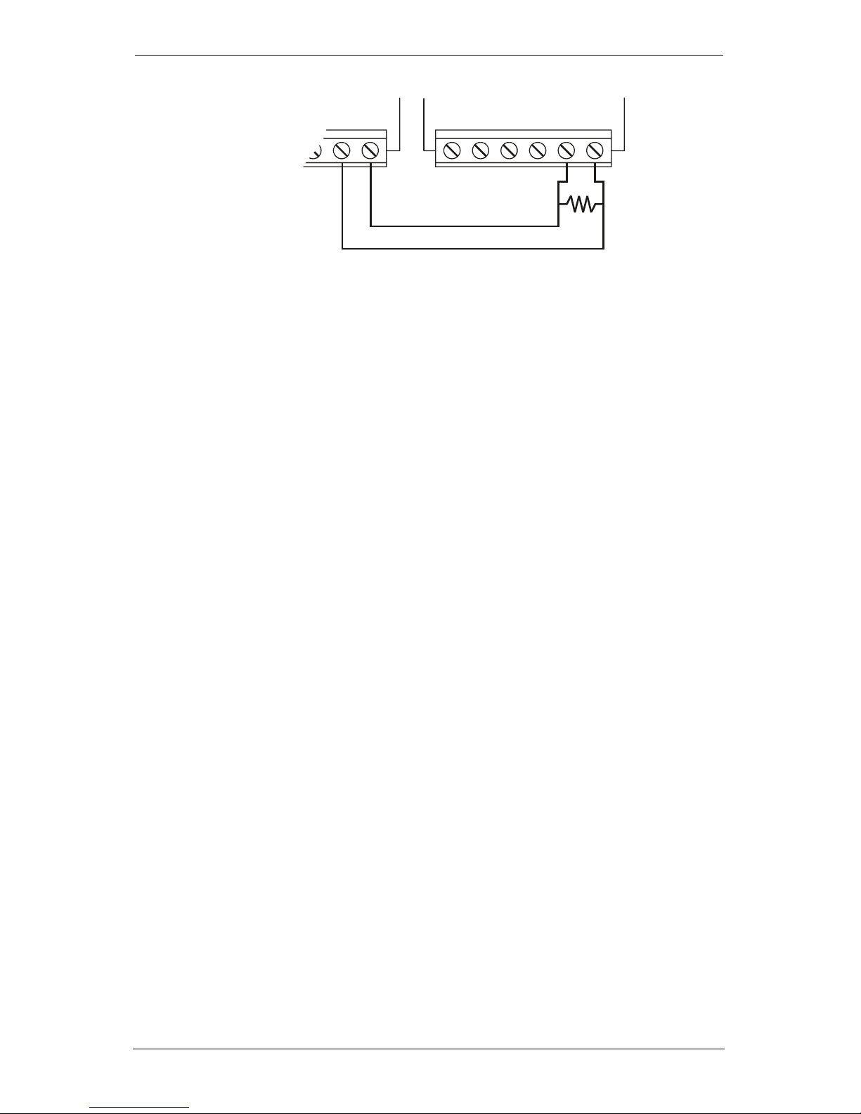
[13] Skyroute CL3050 Trouble Output mask
The PGM output is dedicated for trouble indications. If a control panel is not
monitoring the Skyroute CL3050, an LED or a buzzer can be connected between
this terminal and the RED terminal for a trouble indication. The PGM terminal
switches low from an open-collector state. Connect to the control panel using a
single EOL resistor configuration.
All Modes
Modes 2, 3
All Modes
11
Page 18
Skyroute CL3050 Standalone Wireless Communicator
.
Control Panel
Zx COM
Note:
A relay may be required for proper operation in other configurations.
See paragraph 3.3 Terminal Connections.
Skyroute CL3050
RED BLK YEL GRN COM PGM
5.6K
Ω
Option 1 - Low battery
If the battery voltage drops below 5.72V
battery voltage rises to 5.87V
DC.
Default -
DC
a trouble will be indicated until the
ON
Option 2 - Input Supply Failure
If AC power is absent or if DC power drops below 8.8V
terminals, this
trouble is indicated. Default - ON
Option 3 - Zone Fault/Tamper (DEOL Only)
DC
on the RED and BLK
All Modes
All Modes
Modes 2, 3
A trouble will be indicated if any zone reports a fault or tamper condition. In Section [11], Option [2] must be set to
option to be enabled.
Default -
Option 4 - No Service Available
OFF
OFF
and Option [3] must be set to ON for this
All Modes
This trouble is indicated If the system is unable to detect cellular service.
Default -
Option 5 - Radio Failure
ON
All Modes
This trouble is indicated if there is an internal fault with the cellular radio.
Default -
Option 6 - PC5108 Failure
ON
Mode 3
This trouble is indicated if a PC5108 supervisory or Keybus fault occurs.
Note
The PC5108 tamper is communicated only, therefore it can only be
enabled by turning on section 20 option 7 and section 21 option 5.
There is no local annunciation for this event.
Default -
ON
Option 7 - Failure to Communicate (FTC)
This trouble will be indicated if no acknowledgement has been received from
Connect 24
after three attempts.
Option 8 - Skyroute CL3050 Tamper
This trouble will be indicated if the cover is removed from the Skyroute CL3050
activating the on-board tamper switch.
Default -
Default -
12
All Modes
ON
All Modes
OFF
Page 19

6 Programming Descriptions
[15] System Time
When the time and day have been programmed, the values are saved and are
used as the current time and day whenever the Skyroute CL3050 does a power
up. Time and day programming is only required if the installer desires the Skyroute CL3050 to test transmit at a specific time and/or day. There is no "loss of
time" trouble on the Skyroute CL3050.
Default -
Note
0000 - 2359
If AC Power is detected, it will be used to provide the time base for the
internal clock. If AC power is not detected the internal clock will automatically use the crystal time base.
[16] System Day of the Week
See section [15].
Option 1.
Option 2 - 8.
Default -
ON
Default -
OFF
[17] Test Transmission Time
When the Skyroute CL3050 is powered up for the first time, or after a default
reset; it will check if the test transmission time and day are programmed. If they
are not, a random time (0000 - 2359) will be programmed into this location. The
Skyroute CL3050 will randomly generate this value.
All Modes
All Modes
All Modes
Note:
Due to traffic volume, when selecting test transmission times, select a
time that is not on the :30 minute mark (e.g., 02:24, 04:07)
[18] Test Transmission Day
When the Skyroute CL3050 is powered up for the first time, or after a default, it
will check if the test transmission time and day are programmed. If they are not,
a random day (Sunday-Saturday) will be programmed into this location. The Skyroute CL3050 will randomly generate this value. Because one test transmission
weekly is the most common configuration, this will allow the installer to setup
the Skyroute CL3050 without keypad programming.
Option 1-8.
Default -
[Random]
[20] Transmission Options
When the following options are enabled the reporting codes listed in Appendix A
are sent to
Options 1, 2 - Zone Alarm/Zone Alarm Restores
When a zone is violated or restored, the reporting codes listed in Appendix A will
be sent.
Note:
Connect 24
If generic reporting is enabled and multiple alarms occur during the
delay programmed in Section [23], only one alarm reporting code will
be sent.
.
All Modes
- One only will be enabled.
All Modes
.
Modes 2, 3
Note:
Option 1.
Zone alarm restorals enabled with generic zone reporting enabled can
cause unpaired events to be sent to Connect 24.
Default -
ON, Option 2.
Default -
13
OFF
Page 20

Skyroute CL3050 Standalone Wireless Communicator
Options 3, 4 - Zone Fault, Zone Fault Restores
When the system sees a short circuit across any zone, a zone fault is generated.
DEOL resistors are required for zone fault reporting. In Section [11], Option [2]
must be set to OFF and Option [3] must be set to ON; In Section [13], Option 3
must be set to ON and the Skyroute CL3050 must be operating in mode 2 or 3.
Option 3.
Options 5, 6 - Zone Tamper, Zone Tamper Restores
When the system sees an open circuit across any zone a zone tamper is generated. DEOL resistors are required for zone tamper reporting. In Section [11],
Option [2] must be set to OFF and Option [3] must be set to ON. In Section [13],
Option [3] must be set to ON and the Skyroute CL3050 must be operating in
mode 2 or 3.
Option 5.
Option 7 - System Maintenance Events
When this option is enabled, the maintenance events enabled in Section [21] are
transmitted using the codes listed in appendix A.
Default -
Option 8 - Generic Zones
The Skyroute CL3050 supports generic and detailed zone alarm reporting. By
default, the Skyroute CL3050 will be in generic zone reporting mode. When in
this mode, all zone types are divided into four reporting groups; BA Burg, FA Fire,
PA Panic, UA Technical. If any zone from this group initiates a transmission, the
generic reporting code for this event is sent, additional violations from other
zones from the same group will be ignored until that group's timer has expired.
See table below for zone type grouping.
Default -
Default -
ON,
OFF, Option 4.
OFF, Option 6.
Default -
Default -
OFF
OFF
Modes 2, 3
Modes 2, 3
All Modes
Modes 2, 3
Zone
Ty pe
Null
Burglary
Fire
Panic
Technical
Gas
Heat
Medical
Emergency
Water
Freezer
Sprinkler
Hold-up
Each zone group has it's own timer. The default time is 5 minutes and is programmed in Section [23]. If any zone in a group initiates an event, the timer will
start running and the generic event will be sent. If any additional zones from the
same group initiate an event before that group's timer expires, the event will be
ignored. This generic zone reporting mode only applies to zone alarms. Alarm
restorals, tamper/tamper restorals and fault/fault restorals are not grouped
together into generic reporting groups.
Detailed
Reporting Code
-
BA
FA
PA
UA
GA
KA
MA
QA
WA
ZA
SA
HA
Generic
Reporting Code
-
BA
FA
PA
UA
UA
FA
PA
PA
UA
UA
UA
PA
14
Page 21

6 Programming Descriptions
The generic identifier will be sent with 98 as it's zone number, this is a special
combination recognized by
Connect 24
as a generic event. When the generic
zone reporting toggle is disabled, each zone alarm for each zone type will then
send it's own identifier.
Default -
ON
.
[21] System Event Communication Options
Section [20], Option [7] must be enabled for these events to be communicated.
NOTE:
Option 1 - Input Supply Failure
If AC power is absent or if DC power drops below 8.8V
terminals, a
expired.
trouble will be sent after the delay programmed in section
Default -
ON,
Option 2 - Low Battery
If the battery voltage drops below 5.72V
When the battery voltage rises to 5.87V
Default -
ON.
Option 3 - Skyroute CL3050 Tamper
Removing the cover on the Skyroute CL3050 will send a tamper reporting code
Connect 24
to
.
Default -
OFF
Option 4 - PC5108 Module Fault
Indicates a Keybus communications fault condition.
Default -
OFF.
Option 5 - PC5108 Tamper
Removing the cover on the PC5108 will send a tamper reporting code to
nect 24
.
Default -
OFF.
[22] Input Supply Fail TX Delay
All Modes
DC
on the RED and BLK
[22]
has
All Modes
DC
a trouble will be sent to
DC
the system will send a restore.
Connect 24
.
All Modes
.
Mode 3
Mode 3
Con-
All Modes
This value determines the delay (default 0700 = 7 hrs) before an input supply failure reporting code is sent if programmed. See Section [21], Option [1] and Section [20], Option [2].
Default -
0700 (=7 hrs)
[23] Generic Zone Reporting Timer
This hex value determines the delay before a generic zone reporting code is sent,
if programmed in Section 20 Option 8.
Note:
Default -
There are four separate timers for Burglary, Fire, Panic and Supervisory;
the delay programmed is the same for each timer.
1E (300 seconds / 5 minutes) Range equals 01-FF Hex seconds x 10
Modes 2, 3
15
Page 22
Skyroute CL3050 Standalone Wireless Communicator
7 Programming Worksheets
Zone Definitions (For Sections [01] -[02])
00 Null Zone (Not Used)
01 Burglary
02 Fire
03 Panic
04 Technical
05 Gas
06 Heat
[01] Zone 1-2 Definitions
Default Default
01
[02] Zone 3-8 Definitions
Default Default
01
01
01
[03] Zone 1-2 Loop Response
Default Default
05
I___I___I Zone 1
I___I___I Zone 3
I___I___I Zone 5
I___I___I Zone 7
01-FF (Hex 0.1 second increments), mode 2 only
I___I___I Zone 1
07 Medical
08 Emergency
09 Water
10 Freeze
11 Sprinkler
12 Hold-up
13 TLM Monitor (1 zone max.)
01
I___I___I Zone 2
01
I___I___I Zone 4
01
I___I___I Zone 6
01
I___I___I Zone 8
05
I___I___I Zone 2
[10] Skyroute CL3050 Mode of Operation
Default
01
[11] Skyroute CL3050 Configuration Options 1
Default Opt Option On Option Off
OFF
ON
OFF
OFF
ON
OFF
OFF
OFF
[12] Skyroute CL3050 Configuration Options 2
Default Opt Option On Option Off
ON
ON
I___I___I 01 - Bell Follower, 02 - 2 Zone, 03 - 8 zone (PC5108 )
I___I
I___I
I___I
I___I
I___I
I___I
I___I
I___I
I___I 1 Swinger Shutdown Enabled Swinger Shutdown Disabled
I___I 2-8 For Future Use
1
A Channel selected B Channel selected
2
Normally Closed Loops End-of-Line Resistors
3
Double End-of-Line Resistors Single End-of-Line Resistors
4
Test Once a Day Enabled Disabled
5
Test Once a Week Enabled Disabled
6
Enrolled with
7 System Use
8 System Use -
Connect 24
-
Caution: Do not change
Caution: Do not change
Not Enrolled with
Connect 24
16
Page 23

7 Programming Worksheets
[13] Skyroute CL3050 Trouble Mask
Default Opt Option On Option Off
ON
ON
OFF
ON
ON
ON
ON
OFF
[15] System Time
Default Range
0000 I___I___I___I___I 0000-2359 Hrs/Mins
[16] System Day
Default Opt Option On Option Off
ON
OFF
OFF
OFF
I___I
I___I
I___I
I___I
I___I
I___I
I___I
I___I
I___I
I___I
I___I
I___I
1
Low Battery Disabled
2
Input Supply Failure Disabled
3
Zone Fault/Tamper (DEOL only) Disabled
4
No Service Available Disabled
5
Radio Failure Disabled
6
PC5108 Failure Disabled
7
Failure to Communicate Disabled
8
Skyroute CL3050 Tamper Disabled
1
Sunday Disabled
2
Monday Disabled
3
Tuesday Disabled
4
Wednesday Disabled
OFF
OFF
OFF
OFF
[17] Test Transmission Time
Default Range
Random I___I___I___I___I 0000-2359 Random on power up
[18] Test Transmission Day *Selected at random on power up
Default Opt Option On Option Off
*
*
*
*
*
*
*
I___I
I___I
I___I
I___I
I___I
I___I
I___I
I___I
I___I
I___I
I___I
5
Thursday Disabled
6
Friday Disabled
7
Saturday Disabled
8 For Future Use
1
Sunday Disabled
2
Monday Disabled
3
Tuesday Disabled
4
Wednesday Disabled
5
Thursday Disabled
6
Friday Disabled
7
Saturday Disabled
*
I___I
8
For Future Use
17
Page 24

7 Programming Worksheets
[20] Transmission Options
Default Opt Option On Option Off
ON
OFF
OFF
OFF
OFF
OFF
ON
ON
[21] System Event Communication Options
Default Opt Option On Option Off
ON
ON
OFF
OFF
OFF
OFF
[22] Input Supply Fail TX Delay
I___I
I___I
I___I
I___I
I___I
I___I
I___I
I___I
I___I
I___I
I___I
I___I
I___I
I___I
1
Zone Alarms Disabled
2
Zone Alarm Restores Disabled
3
Zone Fault Disabled
4
Zone Fault Restores Disabled
5
Zone Tamper Disabled
6
Zone Tamper Restores Disabled
7
System Maintenance Events Disabled
8
Generic Zone Reporting Detailed Zone Reporting
1
Input Supply Failure Disabled
2
Low Battery Disabled
3
Skyroute CL3050 Tamper Disabled
4
PC5108 Module Fault Disabled
5
PC5108 Tamper Disabled
6-8
For Future Use
Default Range
0700
I___I___I___I___I 0000-2359 Hrs/Mins
18
Page 25

Glossary of Terms
Glossary of Terms
Cellemetry
Connect 24
RSSI
SID
MIN
Page
Registration
A network allowing short data packets to be sent on cellular control
channels.
Connect 24 is the service provider that provides the Skyroute service to
the security industry and links the Skyroute cellemetry communicator
to the central station.
Radio Signal Strength Indication - This value is transmitted to
24
during the periodic test transmission and can be viewed after
power up by pressing the enroll button.
System Identification Number - ID Number of the Cellular provider
Mobile Identification Number - The 10 digit decimal number used for
registrations and pages (the phone number of the Skyroute CL3050).
A transmission that is sent from the Cellemetry Gateway to the Cellemetry Radio
A transmission that is sent from the Cellemetry Radio to the Cellemetry
Gateway
Connect
19
Page 26
Skyroute CL3050 Standalone Wireless Communicator
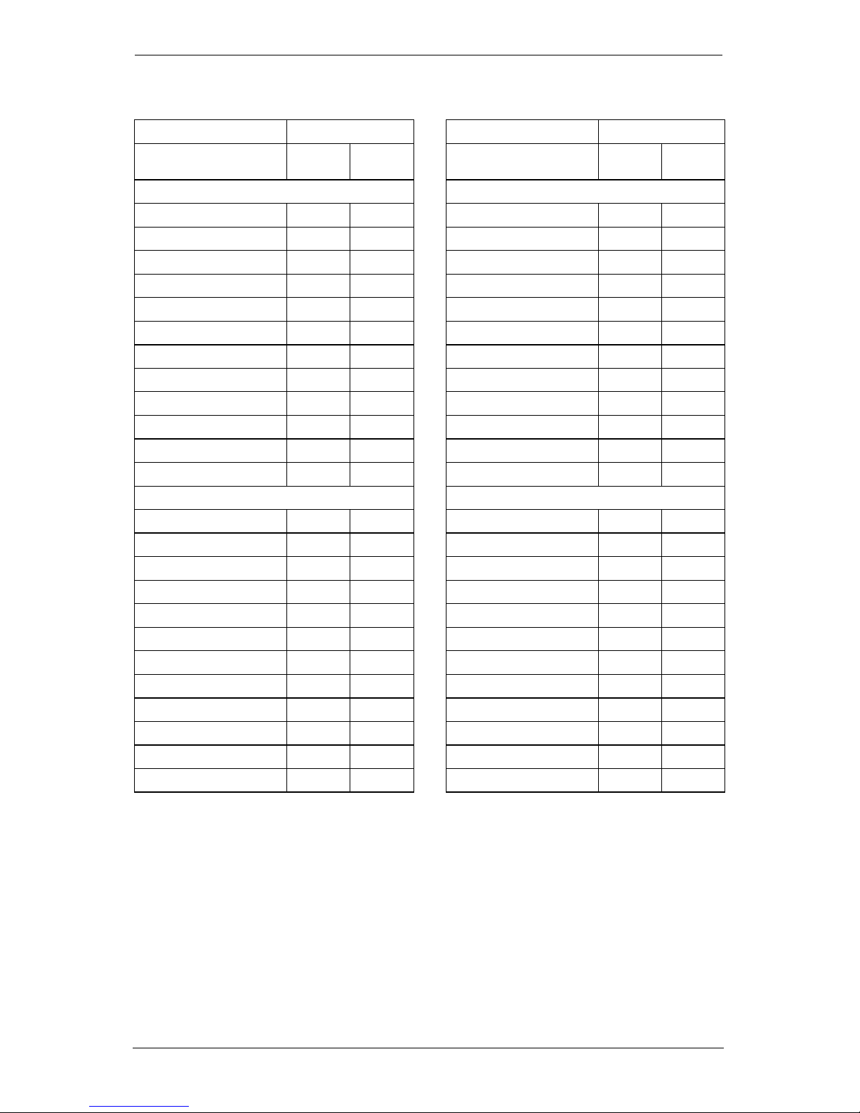
Appendix A: Reporting Codes
Events Reporting Codes Events Reporting Codes
SIA
Zone Alarms Zone Restores
Burglary Zone BAXX E130 Burglary Zone BHXX R130
Fire Zone FAXX E110 Fire Zone FHXX R110
Panic Zone PAXX E120 Panic Zone PHXX R120
Technical Zone UAXX E140 Technical Zone UHXX R140
Gas Zone GAXX E151 Gas Zone GHXX R151
Heat Zone KAXX E158 Heat Zone KHXX R158
Medical Zone MAXX E100 Medical Zone MHXX R100
Emergency Zone QAXX E120 Emergency Zone QHXX R120
Water Zone WAXX E154 Water Zone WHXX R154
Freezer Zone ZAXX E140 Freezer Zone ZHXX R140
Sprinkler Zone SAXX E110 Sprinkler Zone SHXX R110
Hold-up Zone HAXX E122 Hold-up Zone HHXX R122
Zone Fault Alarms Zone Fault Restores
Burglary Zone UTXX E300 Burglary Zone UJXX R300
Fire Zone FTXX E373 Fire Zone FJXX R373
Panic Zone UTXX E300 Panic Zone UJXX R300
Technical Zone UTXX E300 Technical Zone UJXX R300
Gas Zone UTXX E300 Gas Zone UJXX R300
Heat Zone UTXX E300 Heat Zone UJXX R300
Medical Zone UTXX E300 Medical Zone UJXX R300
Emergency Zone UTXX E300 Emergency Zone UJXX R300
Water Zone UTXX E300 Water Zone UJXX R300
Freezer Zone UTXX E300 Freezer Zone UJXX R300
Sprinkler Zone STXX E200 Sprinkler Zone SJXX R200
Hold-up Zone UTXX E300 Hold-up Zone UJXX R300
Contact
ID
SIA
Contact
ID
20
Page 27
Appendix A: Reporting Codes
Event Reporting Code Event Reporting Code
SIA
Zone Tamper Alarms Zone Tamper Restores
Burglary Zone TAXX E137 Burglary Zone TRXX R137
Fire Zone FTXX E373 Fire Zone FJXX R373
Panic Zone TAXX E137 Panic Zone TRXX R137
Technical Zone TAXX E137 Technical Zone TRXX R137
Gas Zone TAXX E137 Gas Zone TRXX R137
Heat Zone TAXX E137 Heat Zone TRXX R137
Medical Zone TAXX E137 Medical Zone TRXX R137
Emergency Zone TAXX E137 Emergency Zone TRXX R137
Water Zone TAXX E137 Water Zone TRXX R137
Freezer Zone TAXX E137 Freezer Zone TRXX R137
Sprinkler Zone STXX E200 Sprinkler Zone SJXX R200
Hold-up Zone TAXX E137 Hold-up Zone TRXX R137
Generic Zone Events System Events
Generic Burglary BA98 E130
Generic Fire FA98 E110
Generic Panic Zone PA98 E120
Generic Supervisory UA98 E140
Contact
ID
98
98
98
98
Input Supply Fail
Trouble
Input Supply Fail
Restore
Low Battery Trouble YT00 E302
Low Battery Restore YR00 R302
Skyroute CL3050
Tamper Alarm
Skyroute CL3050
Tamper Restore
PC5108 Tamper Alarm TA00 E330
PC5108 Tamper Restore TR00 R330
PC5108 Supervisory
Trouble
PC5108 Supervisory
Restore
Periodic Test
Transmission
SIA
YP00 E312
YQ00 R312
TA00 E137
TR00 R137
ET00 E330
ER00 R330
TXZZ E603
Contact
ID
21
Page 28

Forward comments about this manual to: [email protected]
©2002 Digital Security Controls Ltd.
Toronto • Canada • 1-800-387-3630
www.dsc.com
Printed in Canada 29034531r001
 Loading...