

Page 1

NOTE: Due to high volume reproduction of this manual,
screen shots of the software included are not high
quality. For clearer images, print manual internally
(available on enclosed CD-ROM).
Software Package
WARNING: THIS DOCUMENT IS THE PRIVATE
PROPERTY OF SG SECURITY COMMUNICATIONS.
IT CONTAINS CONFIDENTIAL INFORMATION AND
IS NOT TO BE COPIED OR DISTRIBUTED.
User Manual
Version 1.00
Page 2

TABLE OF CONTENTS
INTRODUCTION 1
THE REPORTER FEATURES 1
REQUIREMENTS 1
MINIMUM ................................................................................ 1
ECOMMENDED COMPUTER CONFIGURATION ............................... 1
R
UMBER OF LINE CARDS SUPPORTED......................................... 1
N
INSTALLATION AND SETUP 1
GENERAL FUNCTIONALITY 2
LOG IN / LOG OUT .................................................................. 2
Administration Log In .................................................... 2
User Management ........................................................ 2
User Log In ................................................................... 2
Changing Password ...................................................... 3
RAFFIC SCREEN..................................................................... 3
T
ONFIGURATION ...................................................................... 4
C
Communications ........................................................... 4
Access .......................................................................... 4
Miscellaneous ............................................................... 4
ATA BASE ............................................................................ 5
D
Database Navigation Icons ........................................... 5
First Record ............................................................... 5
Previous Record ........................................................ 5
Next Record............................................................... 5
Last Record ............................................................... 5
Insert Record ............................................................. 5
Delete Record............................................................ 5
Edit Record ................................................................ 5
Post Record ............................................................... 5
Cancel Edit ................................................................ 5
Reports ...................................................................... 5
Edit Database ............................................................... 5
Alarms........................................................................ 5
Notification Contacts .................................................. 6
Countries ................................................................... 6
States/Provinces ........................................................ 6
Actions ....................................................................... 7
Responses................................................................. 7
How to Attach an Action to a Response ................ 7
How to Link the Actions ......................................... 7
Classes/Types ........................................................... 8
Account Type ......................................................... 8
How to add an Account Class................................ 8
ACCOUNTS 8
ACCOUNT SET-UP (METHOD A) .......................................... 8
Address Tab .............................................................. 8
Client Contacts Tab ................................................... 8
Additional Information Tab......................................... 9
Installation Tab .......................................................... 9
Comments Tab .......................................................... 9
Schedules Tab......................................................... 1 0
Opening................................................................ 10
Closing ................................................................. 1 0
Test ...................................................................... 10
Alarm Set-up ........................................................ 10
Exceptions ........................................................... 10
Test On/Off Box....................................................... 1 0
CCOUNT SET-UP (METHOD B) ........................................ 10
A
HISTORY 11
DETAILED REPORTS ......................................................... 11
USTOMER REPORTS....................................................... 11
C
DEBUG 11
ABOUT 12
HELP 12
WHAT'S THIS HELP 12
EXIT 12
ALARM ACKNOWLEDGEMENT 12
"INTERNAL" ALARMS CHART 14
APPENDIX A - REPORTER COMMUNICATION FORMATS 15
APPENDIX B - FORMAT LIBRARY 16
Page 3

INTRODUCTION
This document is designed to help the user to understand
the functionality of The Reporter, the approach to performing
operations and the sequence to follow when using The
Reporter. This user manual is based on the first revision of
the software that is packaged with it. This manual may be
used for the future software revisions but does not guarantee
the coverage of all the features and functionality of the future
software releases.
read and followed.
contain screen shots of The Reporter to better express and
outline the instructions to the user.
It is very critical that this manual be
All the sections outlined in the manual
THE REPORTER FEATURES
- Alarm Priorities, by number and color
- Custom defined alarm priorities
- Custom defined alarm definitions
- Ability for user to edit, add or remove alarms from
the data base
- Inter-linked contacts and responses
- Ability to add, remove and edit account information
- History generated
- Auto logging provided
- Visual and audio annunciation for new alarms
- 500 accounts per PC Receiver card installed
- SG-PCLC2 supervision
- Multiple format support (see Appendix A)
- Time and date stamped on all of the received
and processed alarms
- Log file created for activity
- For use with SG-PCLC2 only
- Multiple alarm acknowledgement
- Alarms and alarm restoral linking
REQUIREMENTS
The following is the required equipment and
specifications of the system:
• IBM compatible PC
• CD ROM
• Reporter Installation CD
• SG-PCLC2 Installed
RECOMMENDED COMPUTER CONFIGURATION
• Windows 9X/NT operating system
• Pentium II, 233MHz processor (or better)
• 64 MB RAM (or higher)
• 1024X768 pixels, 16 bit color video card (or better)
• SVGA monitor
• Mouse
• Windows compatible sound card
• Keyboard
NOTE: The Reporter is specifically designed for use with
Windows 9X/NT operating systems. It will not run under
windows emulators (Wine, VM ware, OS booter and others).
NUMBER OF LINE CARDS SUPPORTED
The Reporter will support the maximum PC-LC2 configuration
per PC, which is 4 PC LC2’s per PC (8 lines). Each line has
a 250-account support, for 2000 accounts when in maximum
configuration. The Reporter automatically calculates the number
of accounts based on the number of PC-LC2 line cards installed
in a PC.
INSTALLATION/SETUP
To set up The Reporter software in Windows 95/98/NT:
1. Insert the CD-ROM into your CD-ROM drive.
2. Go into your CD-ROM drive. Double-click on "The Reporter
Demo Software" folder. Find the "SETUP.EXE" icon and
double-click on it to start The Reporter installation.
3. Follow the instructions shown on your screen. A message
is displayed when SETUP is complete. When entering The
Reporter software, it will ask you for a login and password.
Enter as follows: LOGIN: supervisor PASSWORD: cafelatte
4.NOTE: Once you are in the "User Management" screen,
you MUST add yourself a new User and Password since
the default password automatically expires upon first
login.
MINIMUM COMPUTER CONFIGURATION
• Windows 9X/NT operating system
• Multimedia PC, Pentium 166MHz
• 32 MB RAM
• 800x600 pixels, 16 bit color video card
• SVGA monitor
• Mouse
• Windows compatible sound card
• Keyboard
WARNING: IT IS RECOMMENDED TO RUN THE REPORTER
AS THE PRIMARY APPLICATION ON YOUR COMPUTER;
AT LEAST 50% OF THE COMPUTER'S RESOURCES MUST
BE AVAILABLE FOR THE REPORTER TO FUNCTION
PROPERLY. IT IS ALSO RECOMMENDED TO HAVE NO
SCREEN SAVERS RUNNING OR ANY OTHER POWER
SAVER MODE ON.
1
Page 4

NOTE: Due to high volume reproduction of this manual, screen shots of the software included
are not high quality. For clearer images, print manual internally (available on enclosed CD-ROM).
GENERAL FUNCTIONALITY
This section contains the General Functions of The Reporter.
LOG IN / LOG OUT
The Reporter supports two different operator levels, administrator
and “user”. An Administrator has full access to The Reporter
functions where as the User’s access is limited to
“acknowledgement” functionality.
Note: The Reporter is designed so that only one instance of
the application can be running on one machine at a time.
When The Reporter is started, the screen shown above is displayed
with SG Security Communications information. Point your mouse
pointer to the CD (animation will be displayed). Click on it to get
into the log in prompt.
In this screen enter your new password and re-enter the
password to confirm it. The password must be at least 3
characters long. Once you have entered your password twice
for confirmation, the “submit” icon will be activated. Press on
the submit button for approval of your new password.
If your new password is a duplicate of the original password
that was supplied to you by your administrator the screen
shown above will be displayed. Please select another password
in this case.
Note: To select a unique password, select a password
having alphanumeric characters.
If the password you typed was unique then the screen will
read “password successfully changed”.
User Management
Administrator Log In
If you are an administrator and logging on for the first time after
installation, type supervisor as your log in name and cafelatte
as the password in the appropriate locations in the screen below.
Once you have entered your provided log in name and your
password, the “submit” button is activated. Click on the submit
button. On the same screen you will be notified that there is
a need for change of your password.
As noticed on the screen the text in Red notifies the expiration
of your password.
This feature is only available to the operator with administrative
access. The user management is a feature that allows the
administrator to add new operators, edit existing operators,
or delete operators. The user management function can be
accessed from the file menu.
In this screen, the administrator can add new operators, edit the
existing ones and delete operators that should no longer have
access to The Reporter.
User Log In
If you are a user and logging in for the first time, type your
provided login name and password in the appropriate locations,
as shown in the screen below.
2
Page 5

Once you have entered your provided log in name and your
password, the “submit” button is activated. Click on the submit
button. On the same screen you will be notified that there is
a need for change of your password.
Changing Password
As noticed on this image the text in Red notifies the expiration
of your password.
In this screen enter your new password and re-enter the
password to confirm it. The password must be at least 3
characters long. Once you have entered your password twice
for confirmation, the “submit” icon will be activated. Press on
the submit button for approval of your new password.
If your new password is a duplicate of the original password
that was supplied to you by your administrator the screen
shown above will be displayed. Please select another password
in this case.
Note: To select a unique password, select a password having
alphanumeric characters.
Changing passwords is one of the very important functions
that an operator should perform. This is done for security
purposes. To change your log in password, go to the “change
password” in the file menu.
When “change password” from the File menu is selected, the
screen shown is displayed. In this screen, the password can
be changed.
Note: At the bottom of the screen, “password not changed”
will be shown until password is typed again for confirmation
and the “submit” button is pressed. If a particular password
that you have typed is not changed then type another one
and submit it.
TRAFFIC SCREEN
The traffic screen is the main screen of The Reporter, and is
the first displayed upon log in. The main function of the traffic
screen is to display all the alarms received in priority/
chronological order.
Information seen on the traffic screen from left to right is:
• Time/Date • Priority • Account Number
• Alarm Event • Partition • Zone
• Alarm Definition • Open/Close • Ack’d
If the password you typed was unique then the screen will
read “password successfully changed”.
The above screen shows several alarms of different priorities.
This screen also shows full access to functionality as operator
is logged on as administrator.
3
Page 6

The above screen shows several alarms of various priorities.
This screen shows limited accessibility as operator is logged
on as a user only.
Note that several icons are no longer accessible.
CONFIGURATION
The Reporter has configuration settings to set custom
parameters per receiver connected. This version of The Reporter
is compatible only with the PC-LC2 receiver.
From the traffic screen, the administrator can access this
screen by pressing the Configuration icon, shown above.
This screen allows operator to customize three types of settings:
• Communication
• Access
• Miscellaneous
NOTE: AFTER MAKING ANY CHANGES TO THE
CONFIGURATION SETTINGS OF THE REPORTER, THE
REPORTER MUST THEN BE RESTARTED.
Access
The access tab consists of:
• Password Expire Period - Allows administrator to pre-set
the duration that a password is valid. 40 days is the default.
• Number of Pending Alarms Before Warning - The Reporter
will notify the operator that there are a certain number of
pending alarms (un-acked) on the traffic screen. This allows
admisitrator to set the number of alarms pending before
The Reporter will prompt the operator. By default, this is
set to 50 un-acknowledged alarms.
• Auto-Logout Delay - The Reporter will automatically log out
if sitting dormant for the period set here. This allows the
administrator to set the period (in minutes). This is defaulted
to 15 minutes, the maximum duration is 99 minutes.
• No Auto-Logout - This check box allows administrator to
decide not to allow for The Reporter to auto-logout, this is
the default setting.
Miscellaneous
Communications
The communication tab consists of:
• Receiver Type - the receiver that is being used.
• Port - the port to which the receiver is connected.
• Baud Rate - the baud rate of the receiver’s output.
• Databits - the number of databits of the receiver’s output.
• Parity - the type of parity of the receiver’s output.
The Miscellaneous tab consists of the “Bring to the Front
Mode”:
• Windows 95 Compatible - In this mode, The Reporter will
become the active application (brought to the front) each
time there is a new alarm received.
• Windows 98/NT Compatible - In this mode, The Reporter
ICON on the tool bar will flash when a new alarm is received.
NOTE: In order for this to operate properly, the tool bar
must not be on “auto hide.”
4
Page 7
DATA BASE
This section in The Reporter contains the database, which
stores the generic alarm definitions library, contacts, actions,
countries, states, responses, and class/types. Upon initial
installation there will be data only in the fields listed below.
- Alarm
- Countries
- States
- Classes/Types.
All the fields in the database can be edited at the discretion
of the administrator(s).
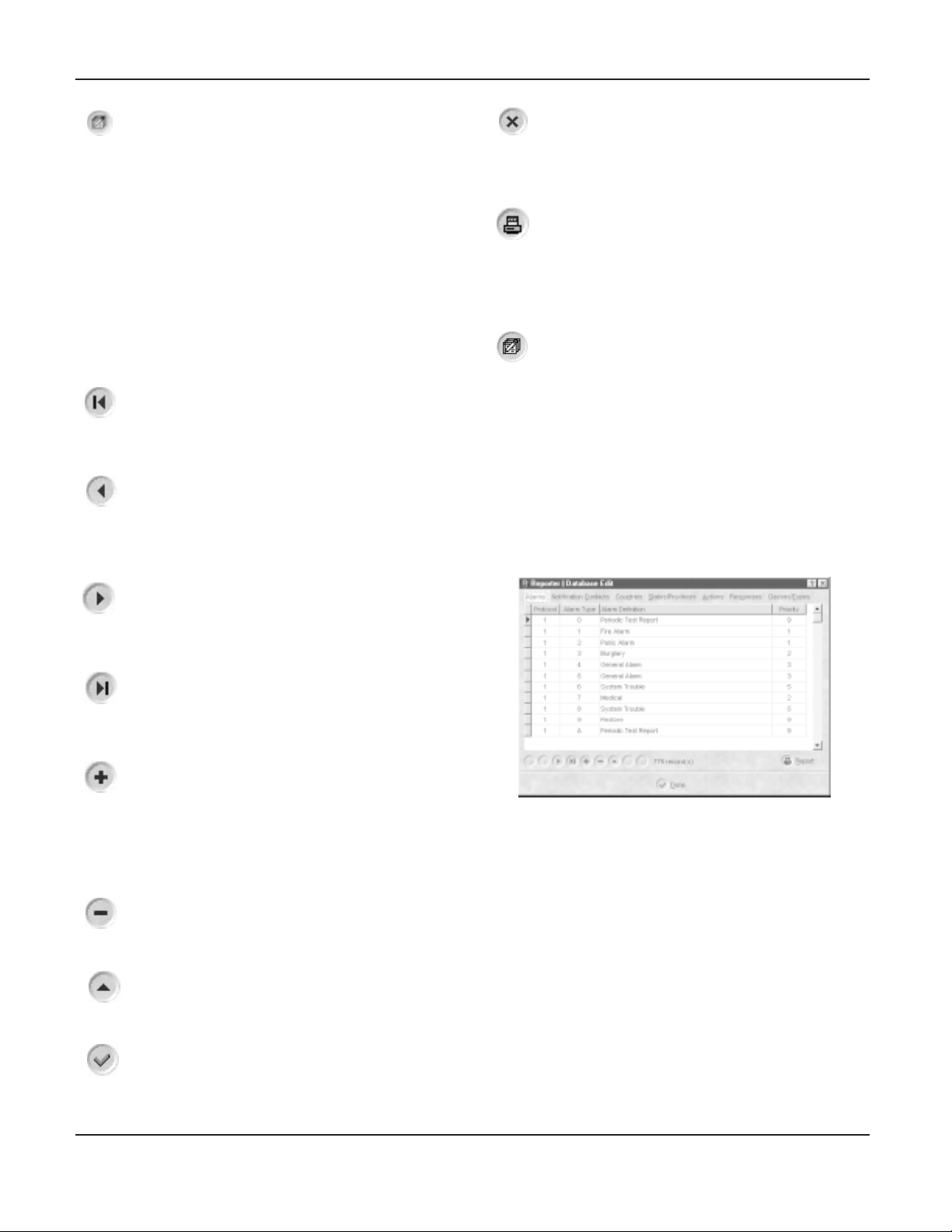
Database Navigation Icons
There are nine navigation icons globally used throughout
The Reporter database screens.
First Record
This icon returns operator to the first record in the database.
This icon becomes deactivated when viewing the very first
record in the database.
Previous Record
This icon takes operator from current record to the previous
record in the database. This icon becomes deactivated when
the operator attempts to access the previous record from the
first record in the database.
Cancel Edit
This icon is used to cancel the edit or addition of a new
record in the database. If any field has been changed
accidentally, this icon can be pressed to cancel the changes
made and return the record to its previous state.
Reports
This icon is used to print the database in current view on
your windows default printer. This icon is available on
almost all the screens of The Reporter database, so you
can print out all the necesary information.
EDIT DATABASE
It is necessary to update/edit the database for customization
of information used in The Reporter. There are seven different
sections to the database, and each are described in detail.
• Alarms
• Contacts
• Countries
• States
• Actions
• Responses
• Classes/Types
Alarms
Next Record
This icon takes operator to the next record in the database.
This icon becomes deactivated when operator attempts to
access the next record from the last record in the file.
Last Record
This icon brings operator to the last record in the database.
This icon becomes deactivated once the last record has
been reached.
Insert Record
This icon is used to insert new records in the database. Use
this icon to enter a new account, or enter any other record
in the database. This icon becomes deactivated once pressed
and becomes active when either cancel button is pressed or
post record is pressed. When inserting a record, all other
icons except “post” and “cancel” become deactivated.
Delete Record
This icon will delete the record that is currently being viewed.
The record will be permanently removed from the database.
Edit Record
Use this icon when there is a need to change one of the
fields in the database.
Post Record
This icon is used to save new record entries, and save
changes made to existing entries.
This is the default database for all the alarms received.
When The Reporter receives an alarm, the definitions and
priorities are taken from this table. It is recommended not
to change the default definitions of the alarms unless
necessary. If an addition to an alarm library is required
then follow the very simple process outlined below:
• Press the “+” icon, note that a blank row is created.
• Click the mouse pointer in the “protocol” column. You can
either type in the protocol id of the alarm being added or
select one by clicking down on the arrow and selecting from
one already listed. E.g. for Contact ID the protocol id is 5.
• Once the protocol id has been selected, click in alarm type
column and type the new alarm.
• Next, click in alarm “Alarm Definition” section and type in
the alarm definition that is to appear on the traffic screen.
It is recommended to type the standard (accepted) definition
if an update is made to the alarm library.
5
Page 8
• The priority of the alarm is to be entered next. Click in the
“priority column” and either type in the default priority of
the alarm (0 to 9) or select by clicking the down arrow that
is shown in the priority column.
• When completed, click on the “check mark” (post) to save
the latest changes and/or additions to the alarm database.
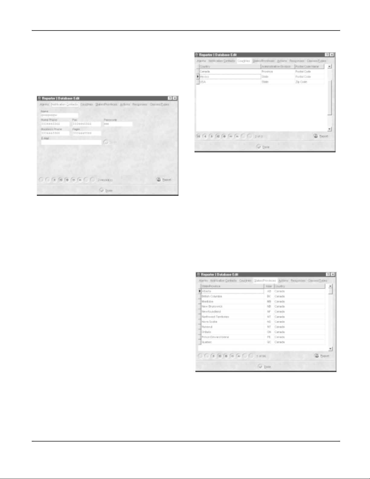
Notification Contacts
This is the field where all of the necessary contact information
is entered. These entities require notification when
acknowledging alarms.
NOTE: “Generic” type contacts are entered here, such as
fire and police departments.
To add a contact, follow the steps listed below:
• Press “+” sign at the bottom of the screen (a blank form is
provided)
• Enter the name of a person or organization to be contacted
in case of an alarm
• Enter their phone number in the “home phone” field
• Enter the fax number of the person or the organization in
the “fax” field
• Enter the business phone number of the person or organization
in the “business phone field” (optional)
• Enter the pager phone number of the person or organization
in the “pager” field (optional)
• Enter the email address of the contact in the “email” field
• Enter the Passcode in the “passcode field.” The passcode
is used to identify that the correct person has been reached.
• When completed, click on the “check mark” (post) to save
the latest changes and/or additions to the contact database.
Countries
In this section, any country of the world can be added to the
list if not already present in the database.
Follow these steps to add a country to the database.
• Press “+” sign at the bottom of the screen (a blank line is
provided)
• In the column “country,” type the name of the country and
press enter
• Click with your mouse in the “administrative division” and
double click on the right side of the column, note that a
down arrow appears. Click on the down arrow and select
one of the provided selections e.g. Province, region, state
or territory
• Click on the “postal code name” column and type in the
name of the postal code e.g. Postal code, or zip code
• When completed, click on the “check mark” (post) to save
the latest changes and/or additions to the contact database.
States/Provinces
This section is used to enter the names of States/Provinces in
conjunction with the country in which it is located. This is used
to enter a State/Province that is not already present in the database.
Follow the steps below to add a new State/Province:
• Press “+” sign at the bottom of the screen (a blank line is
provided)
• Type in the name of the state/province/territory or region
and press “enter.”
• Enter the two-character abbreviation in the “abbr” field if
used (optional)
6
Page 9
• Click in the “country” column to select from a country in the
list (these countries are the same as entered in the
“countries” screen.
• When completed, click on the “check mark” (post) to save
the latest changes and/or additions to the contact database.
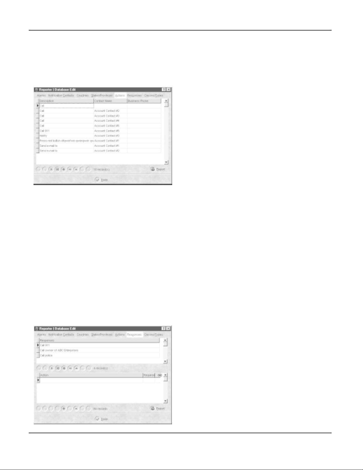
Actions
Actions are a very important part of the acknowledgement
process. This screen enables the operator to customize the
actions per account.
To add an action, follow the steps below:
• Press “+” icon at the bottom of the data base screen (a
blank line will be provided)
• Click in the “ description” column, and either choose an
action from the list, or enter a new one.
• Next, click in the “contact name” field. Select from a contact
in the list (these contacts are the same as those entered
in the contact field). Notice that when you select a contact,
the number automatically appears in the business telephone
column.
• A business number can also be chosen by clicking in the
“business phone” column. Notice that entering a number
in this field will automatically select the contact associated
with the number.
• When completed, click on the “check mark” (post) to save
the latest changes and/or additions to the contact database.
Responses
The responses are interrelated to the actions and they are
used when acknowledging the alarms. In order for the responses
to be useable, they have to be entered properly and assigned
to the alarm accounts at the time of account set up. They
can also be assigned to the account’s alarms later by editing
the account. Different responses can be assigned to different
alarms within an account.
To add a new response, follow the steps below:
• Press “+” icon at the bottom of the data base screen (a
blank line will be provided)
• Enter a label for the response
• When completed, click on the “check mark” (post) to save
the latest changes and/or additions to the contact database.
How to attach an Action to a Response
Follow steps listed below to attach actions to a response:
• Highlight a response to which an action is to be attached.
• Press “+ “ icon within the action section of the response tab
(a blank line will be provided). Note that you may not be
able to type in this row because it pulls up the actions list
added in the action tab.
• Double click in the blank row for the drop down menu and
select one of the available actions that were previously
entered in the actions tab. If the action is to be a “required”
action, click the “required” field, and a checkmark will appear.
Repeat for all actions to be added to the response.
• When completed, click on the “check mark” (post) to save
the latest changes and/or additions to the contact database.
How to link the Actions
Follow steps below to link the actions:
• Actions can be put into order by dragging the pointer to the
actions up and down. Point the record pointer to the action
and drag with your mouse pointer to the position desired.
(Actions must be “next” to each other in order to be linked).
• You can link multiple actions together as well, except that
all actions being linked must be marked “required”.
• Simply click and hold the mouse pointer in the link column
and drag it to the action that you wish to link it with.
Note: when acknowledging the signal that this response
is assigned to, only the first of the linked actions would
be active. The subsequent linked actions will remain inactive
unless the previous one has failed. Therefore, if you have
multiple contacts (in actions) that require contact in the
event of an alarm, then do not link these actions together.
• Once the above information is verified and entered properly,
click the “done” button.
7
Page 10

Classes/Types
Account Type
The account type (Account Type Name field) contains information
on the type of building in which the account is found.
To add an account type, follow the steps listed below:
• Click in the “Account Type Name” column with your mouse
pointer
• Press the “+” icon to add a new Account Type Name (a
blank row is provided)
• Type the name of the Account Type in the blank space that
is created.
• When completed, click on the “check mark” (post) to save
the latest changes and/or additions to the contact database.
How to add an Account Class
The account class (Account Class Name field) contains
information on the type of account monitored.
To add an account class, follow the steps listed below:
• Click in the “Account Class” with your mouse pointer
• Press the “+” icon at the bottom of the screen to add
Account class (a blank row is provided)
• Type in the name of the Account Class in the blank space
that is created
• When completed, click on the “check mark” (post) to save
the latest changes and/or additions to the contact database.
ACCOUNT SET-UP (METHOD A)
To add a new account, follow the process outlined in the
following sections.
Before you add a new account make sure the country and
the province/state is in the database (This country and province/
state are the fields of which the new account number is
about to be added).
Address Tab
• Press “+” icon at the bottom of the account section (a blank
account form will be provided)
• Enter account number of the account in the “number” field.
Note that this must be a unique number.
• Enter the name of the subscriber in the “name field.”
• Enter the telephone number (with area code) of the subscriber
in the “phone” field.
• Enter the fax number (with area code) of the subscriber in
the “fax” field.
• Enter the class type of the account in the “class” field by
choosing from the list.
• Enter the account type in the “type” field by choosing from
the list.
• Enter the complete address of the customer in the
“address” field.
Client Contacts Tab
ACCOUNTS
This is the account database where the monitored accounts
are setup. Note that the top portion is the account database,
and the lower portion is the traffic or activity. There is a
maximum of 500 accounts per PC-LC2 for up to 2000 accounts
with 4 PC-LC2’s installed.
The following fields are located with in the account set-up
screen:
• Account information (all fields with an asterik “*” are mandatory
and must be filled in)
• Address • Contacts • Installation information
• Comments fields • Schedules • Additional information
NOTE: Accounts can only be set-up by Administrator.
8
Page 11

This screen is for the entry of the contacts for the account.
They differ from the notification contacts in that they are
specific to the account, not generic. Also, note that a “Notification
Contact” can be one or more of the client contacts. A maximum
of 5 contacts are allowed for each account.
NOTE: The left most section containing account number,
telephone number and other information is for the entire
account, and is not part of each tab. This information is
entered only once.
• Press “+” icon at the bottom of the account section (a blank
account form will be provided)
• Enter account number of the contact in the “number” field.
Note that this must be a unique number.
• Enter the name of the contact in the “name field.”
• Enter the telephone number (with area code) of the contact
in the “phone” field.
• Enter the fax number (with area code) of the contact in the
“fax” field.
• Enter the pager number (with area code) of the contact in
the “pager” field.
• Enter the email address of the contact in the “email” field.
Additional Information Tab
Installation Tab
Information regarding the installation of the system is
contained here.
• Enter the type of control panel in the “control panel type”
field.
• Enter the location of the control panel in the “control panel
location” field.
• Enter the zone types (either wireless or hardwired) in the
“wireless/hardwire” zones field.
• Enter the location of the control panel transformer in the
“transformer location” field.
• Enter the telephone number of the control panel in the
“panel phone number” field. Note that if this field is left
blank, it will be updated with the received Caller ID from
the PCLC2 (if caller ID enabled). If there is a number
entered here, and caller ID is received from the PC LC2,
then The Reporter will compare the two. If they are not the
same, a “Caller ID mismatch” message will appear.
• Enter the name of the Installer in the “installer name” field.
• Enter the date of installation in the “date of installation”
field.
This field contains more information on the location of the
customer.
• Enter the nearest major or “known” intersection in the “major
intersection” field.
• If there is any type of landmark near the subscriber’s location,
enter this in the “landmark” field.
• If there are any special conditions surrounding the account,
enter this/these in the “special conditions” field. These can
be things such as, wheelchair bound individual living there,
hearing impaired residents, pets, etc.
Comments Tab
This field is complementary to the “special condition” providing
additional information on the account. This field could also be
considered optional but as mentioned above any additional
information could prove to be very critical and beneficial at the end.
9
Page 12

This section has no pre-defined structure, simply enter any
other relevant notes on the account in this section.
Schedules Tab
The Reporter allows for three different schedule types: Opening,
Closing, and test. These signals will be auto-logged and autoacked, as they are priority 0 alarms. They will become active
alarms that require some response only if there is an error in
the schedule.
Opening
• Enter the normal opening time expected from the account
in the “time” field.
• Enter the window in which receiving the opening is acceptable.
If the opening signal is received too early, an alarm is
generated on the traffic screen indicating the opening was
received too early. If the opening signal is received too late,
an alarm is generated on the traffic screen indicating the
opening was received too late. As long as the opening is
received within the window, no action is necessary from the
operator.
Closing
• Enter the normal closing time expected from the account in
the “time” field.
• Enter the window in which receiving the closing is acceptable.
If the closing signal is received too early, an alarm is generated
on the traffic screen indicating the closing was received too early.
If the closing signal is received too late, an alarm is generated
on the traffic screen indicating the closing was received too
late. As long as the closing is received within the window, no
action is necessary from the operator.
Test
• Enter the normal time the test signal is expected from the
account in the “time” field.
• Enter the window in which receiving the test signal is
acceptable.
If the test signal is not received within this window, a message
will be generated on the traffic screen indicating the test
signal has failed. As long as the test signal is received within
the window, no action is necessary from the operator.
Alarm Setup
This allows you to customize the alarm definitions, zone
definition and assign a particular response on that event for
the operator to process this specific event for that particular
customer.
Follow the outlined instructions below to setup custom alarms:
• Click "+" (the add record icon)
• Note that a blank row is created with a default parity of "5"
(medium).
• You can type in the priority column, or double-click to pick
one of the other priorities besides "0" if you wish.
• Now type in the alarm code that you wish to customize (type
exactly
it in
• Define this alarm in the alarm definition column.
• Type in the zone, if any, that will be received.
• Define the zone that was just entered.
• Now click in the partition column and enter a partition number,
if any, that will be received with the alarm code.
• If you wish to assign a response to this alarm, double click
in the response column and select from one you have already
entered.
• If the response you wish to assign is not in the list, then you
can create the response in the database edit section later,
and then return to this section of The Reporter to assign the
newly created response.
the way you will receive it on your traffic screen).
NOTE: If no response is assigned, the standard
acknowledgement will be used.
• Once the alarm is set, this alarm definition will take precedence
over the default definition and will be displayed on the traffic
screen every time this alarm is received from this particular
account.
• Multiple alarms from the same account should be acknowledged
once if they have the same response assigned.
Exceptions
The Reporter allows for “exceptions” to the schedule. Exceptions
are used for such things as Holidays.
• Press “+” to enter a new schedule. (A calendar appears)
• Click the appropriate month and day from the calendar
• Use the “annual event” checkbox to indicate whether the
exception is to recur each year. If the exception is for the
current year only, then do not enable the checkmark in this
box. Note that the year will appear next to the month and
day in the Holidays list.
Test On/Off Box
The Reporter enables the operator to place the account on
test. The “test on/off” checkbox is used for this. When the
account is in “test mode” all alarms received for the account
code are auto-logged/auto-acked, and require no response
from the operator.
ACCOUNT SET-UP (METHOD B)
The second method of adding a new account is not as simple
but by following this method, you can be sure that all the
account digits are entered properly and the messages are
acknowledged with the right account number. This process of
adding a new account is carried out at the time of installation
of the security panels.
10
Page 13

• Once the security panel is installed you can have a test
messages sent to you
• Once the test message is received it will be displayed on
the traffic screen
• Double click on the alarm to acknowledge it
• When this is done, note that a blank form is brought up with
only the line number, receiver number and the actual account
in the account information field
• Filling out the rest of the form is the same as described in
Method A
HISTORY
The history allows the operator to get a detailed report on
any given account. The reports can be either printed on the
default windows printer or exported to a Microsoft Excel file.
(Microsoft Excel must be installed for this). An account can
be searched to match any of the following criteria:
• Account • Date(Search any date/time, a range of dates)
• Alarms (Drop down menu for a list of available alarms)
Or, simply point your mouse over the ckeck mark and the
operator's comments will be displayed.
DEBUG
The Debug screen is a feature of The Reporter that allows
the operator (administrator only) to see the raw data received
from the SG-PC-LC2. The Debug screen can be shown in
two modes:
• HEX • ASCII
Once the search criteria has been selected, click the “Search
now” button. The results will be displayed in the lower portion
of the window. At this point, a report can be generated for
printing, or the information can be exported to an Excel
spreadsheet.
Two types of reports can be generated.
Detailed Reports:
Time of the received event, time the event was acknowledged,
name of the operator, whether the alarm occured while the
system was armed or disarmed, alarm definition, zone number,
zone definition, and the operator's comments if any were
made at the time of the acknowledgement. The report also
prints a brief account information.
Customer Reports:
This report is generated for the customer's review if required.
It contains the time of the received event, alarm definition,
zone number, and zone definition.
The operator's comments can also be viewed on the screen.
If the comments column has a check mark, this means the
operator made comments for that alarm. You can view the
comments by clicking on the check mark as shown in the
next screen.
<12/4/99 3:57:00 PM> 35 30 31 31 20 31 38 31 32 33 34 45 31 33 30 30 31 31 32 33 14
<12/4/99 3:57:01 PM> 06
<12/4/99 3:57:27 PM> 35 30 31 31 20 31 38 31 32 33 34 45 31 33 30 30 31 31 32 33 14
<12/4/99 3:57:28 PM> 06
<12/4/99 3:57:30 PM> 35 30 31 31 20 31 38 31 32 33 34 45 31 33 30 30 31 31 32 33 14
<12/4/99 3:57:30 PM> 06
<12/4/99 3:57:56 PM> 35 30 31 31 20 31 38 31 32 33 34 45 31 33 30 30 31 31 32 33 14
<12/4/99 3:57:57 PM> 06
<12/4/99 3:57:58 PM> 35 30 31 31 20 31 38 31 32 33 34 45 31 33 30 30 31 31 32 33 14
<12/4/99 3:57:58 PM> 06
<12/4/99 3:57:59 PM> 35 30 31 31 20 31 38 31 32 33 34 45 31 33 30 30 31 31 32 33 14
<12/4/99 3:58:00 PM> 06
<12/4/99 3:58:41 PM> 35 30 31 31 20 31 38 31 32 33 34 45 31 33 30 30 31 31 32 33 14
<12/4/99 3:58:41 PM> 06
<12/4/99 3:58:42 PM> 35 30 31 31 20 31 38 31 32 33 34 45 31 33 30 30 31 31 32 33 14
<12/4/99 3:58:42 PM> 06
<12/4/99 3:58:43 PM> 35 30 31 31 20 31 38 31 32 33 34 45 31 33 30 30 31 31 32 33 14
<12/4/99 3:58:43 PM> 06
Shown above: example of the debug screen viewed in HEX.
<12/4/99 3:57:00 PM> 5011 181234E13001123O
<12/4/99 3:57:01 PM> O
<12/4/99 3:57:27 PM> 5011 181234E13001123O
<12/4/99 3:57:28 PM> O
<12/4/99 3:57:30 PM> 5011 181234E13001123O
<12/4/99 3:57:30 PM> O
<12/4/99 3:57:56 PM> 5011 181234E13001123O
<12/4/99 3:57:57 PM> O
<12/4/99 3:57:58 PM> 5011 181234E13001123O
<12/4/99 3:57:58 PM> O
<12/4/99 3:57:59 PM> 5011 181234E13001123O
<12/4/99 3:58:00 PM> O
<12/4/99 3:58:41 PM> 5011 181234E13001123O
<12/4/99 3:58:41 PM> O
<12/4/99 3:58:42 PM> 5011 181234E13001123O
<12/4/99 3:58:42 PM> O
<12/4/99 3:58:43 PM> 5011 181234E13001123O
<12/4/99 3:58:43 PM> O
<12/4/99 4:47:32 PM> 1011 @0 O
<12/4/99 4:47:32 PM> O
11
Page 14

Shown previously is an example of the Debug screen viewed
in ASCII.
Note that there is information present at the bottom of the
screen (from left to right):
• Cards: X - This indicates the number of PC LC2 line cards
currently being monitored.
• COM2: Opened - Communication between The Reporter
and PC LC2 occurs on this port. “Opened” means the port
is active.
• Receiver: Connected - This indicates that the receiver is
currently connected to The Reporter.
ABOUT
The About Icon is used to access the company information.
This screen shows information about SG Security
Communications:
• Version Number of The Reporter
• Company Logo
• Phone, Fax and “800” numbers
• Web Site address
• Technical Support email address
The web site address is a link, meaning when clicked on it
will open the SG Security Communications web site in the
default browser installed on the operator’s system.
The email address is also a link, and clicking on it will open
a blank email using the default email browser installed.
When completed with this screen, click the “Done” button to
return focus to the traffic screen.
WHAT’S THIS HELP
“What’s this?” is part of the Help section accessed either
from the traffic screen by clicking on the “what’s this?” icon,
or from the Help menu on the menu bar. “What’s this?” is
used for displaying the functionality of any part of the screen
or icons that may not be obvious to the operator by its
appearance.
To access additional information on any section of The Reporter,
simply click the “what’s this” icon and click on any part of
the screen.
Notice that when the “what’s this” icon is clicked, the mouse
pointer is now accompanied by a “?”. When a part of the
screen has been clicked, a window will pop up containing
information on that part of the screen. When the operator
clicks on any other section of the screen or by pressing the
Escape key, the window disappears, and the “what’s this”
mode becomes deactivated.
EXIT
The “exit” icon is used to exit from The Reporter.
ALARM ACKNOWLEDGEMENT
This process could be considered the most critical process for
the operator of The Reporter. Therefore, it must be followed
closely.
This process consists of a number of steps, some of which
are optional. It is recommended to do the optional steps
anyway. The acknowledgment process is logged per operator.
The acknowledgement process is outlined below:
• Double click on an alarm on the traffic screen.
• The account information is brought up with address and
type of account etc. (The information that was entered at
the time of account set up).
• Next, click on the envelope to send an e-mail to the address
entered (if there was no e-mail address entered this icon
will be disabled)
• Next, press the yellow “ACK” button, a new screen will appear.
HELP
There are three ways to access help from the traffic screen.
The first one is to click on the HELP icon with your mouse
pointer. The second way is to access help from the Help menu
on the menu bar. In addition, you may access it from the keyboard
by pressing the function key (F1).
Shown above is the screen that appears when an alarm on
12
Page 15

the traffic screen is double-clicked.
Shown above is the alarm acknowledgement screen (appears
when the yellow “ACK” button is pressed).
This screen shows the following information about the
acknowledgement for the alarm:
• Response
• Action List
• Acknowledgement comments
• Contact Information
The response that is originally assigned to the alarm is brought
up once you are in the "ACK" process. If no response is
assigned, you will be presented with the standard
acknowledgement action.
The action list contains all the optional and required actions
to be performed. Any linked alarms are indicated as well.
• The acknowledgement comments is a field reserved for
the operator. Any comments can be entered and will be
kept in the history log along with the account and alarm
information.
• The Contact information contains the names and numbers
of people that were entered when setting up the response.
• Single click in the "done" column, beside the action, it will
bring out the name and contact information of the action.
• Double click the "done" column when the action has been
performed.
Note: A check mark is placed and the color changes when
the action is completed.
• You will not be able to check the "fail" column unless the
actions are linked together.
13
Page 16

“INTERNAL” ALARMS
The PC LC2 can generate several alarms for trouble conditions it could be experiencing. All of these alarms will
appear on the traffic screen from account “0000”. The chart below contains these internal alarms.
AlarmAlarm Alarm Definitions Zone Zone Definition Priority
Alarm Alarm Definition Zone Zone Definition Priority
0 Printer Error 1 5
0 Printer Restore 2 9
0 12V Battery Low 3 5
0 12 Battery Restore 4 9
0 COM 1 Absent 5 5
0 COM 1 Restore 6 9
0 Tamper Alarm 7 5
0 Tamper Restore 8 9
1 Invalid Report 0 9
1 AC Failure 5 5
1 AC Restored 6 9
2 Telephone Line Fault 0 5
3 Telephone Line Restored 0 9
4 Communication Failed 0 5
D System Reset 0 9
F Line Card Absent 0 Line Card 0 5
F Line Card Absent 1 Line Card 1 5
F Line Card Absent 2 Line Card 2 5
F Line Card Absent 3 Line Card 3 5
F Line Card Absent 4 Line Card 4 5
F Line Card Absent 5 Line Card 5 5
F Line Card Absent 6 Line Card 6 5
F Line Card Absent 7 Line Card 7 5
F Line Card Absent 8 Line Card 8 5
F Line Card Absent 9 Line Card 9 5
F Line Card Absent A Line Card A 5
F Line Card Absent B Line Card B 5
F Line Card Absent C Line Card C 5
F Line Card Absent D Line Card D 5
F Line Card Absent E Line Card E 5
F Line Card Absent F Line Card F 5
E Line Card Restored 0 Line Card 0 5
E Line Card Restored 1 Line Card 1 5
E Line Card Restored 2 Line Card 2 5
E Line Card Restored 3 Line Card 3 5
E Line Card Restored 4 Line Card 4 5
E Line Card Restored 5 Line Card 5 5
E Line Card Restored 6 Line Card 6 5
E Line Card Restored 7 Line Card 7 5
E Line Card Restored 8 Line Card 8 5
E Line Card Restored 9 Line Card 9 5
E Line Card Restored A Line Card A 5
E Line Card Restored B Line Card B 5
E Line Card Restored C Line Card C 5
E Line Card Restored D Line Card D 5
E Line Card Restored E Line Card E 5
E Line Card Restored F Line Card F 5
5
Y Receiver Disconnected • 0 • PC LC 2 5
14
Page 17

APPENDIX A - REPORTER COMMUNICATION FORMATS
Name Handshake Data Baud Format Kiss Of f
EMAN EKAHSDNAH ATAD DUAB TAMROF FFOSSIK
zH
scinoidaR
scinoidaR
DItcatnoC
draG-ruS
draG-ruS
aocseSnilknarF
2&1levelAIS
2/4ro1/4,2/3
2/4ro1/4,2/3
2/4ro1/4,2/3
muskcehc/w1/3
dednetxe1/3
2/4,muskcehc/w
,dednetxe1/3,1/3
,dednetxe1/3,1/3
,dednetxe1/3,1/3
,dednetxe1/3,1/3
zH0041
zH0041
zH0032
zH0032
zH0032
0041wolSocmedA
tsaFthginKtneliS
zH0041zH009101
zH0041zH009141
zH0032zH008102
zH0032zH008104
zH0032zH008104
KRAMKSF
enoTlauD
zH0041
zH0032FMTDFMTD3/4zH0032
enoTlauD
zH0041
KSF
ECAPS/KRAM
FMTDFMTD3/2/3/12/4zH0041
FMTDFMTD3/4zH0032
003/011kcaatadlanoT
2/4
draG-ruS
draG-ruS
tsaFrepuS
ocmedA
tsaFrepuSnorcA
sserpxEocmedA
zH0032FMTDFMTDmuskcehc/w3/4zH0032
enoTlauD
zH0041
enoTlauDFMTDFMTD1/8/4zH0041
zH0041FMTDFMTD8/4,8/3zH0041
enoTlauDFMTDFMTD2/4,1/4zH0041
FMTDFMTDmuskcehc/w3/4zH0041
15
Page 18

APPENDIX B - FORMAT LIBRARY
DIlocotorP )3(epyTmralA )41(noitinifeDmralA ytiroirP
)0000=tcca(110rorrEretnirPM
20erotseRretnirPL
30woLyrettaBV21M
40erotseRyrettaBV21L
50tnesbA1#moCM
60derotseR1#moCL
70mralArepmaTH
80erotseRrepmaTL
01tropeRdilavnIL
51eruliaFCAM
61derotseRCAL
02tluaFeniLenohpeleTM
03derotseReniLenohpeleTL
04deliaFnoitacinummoCM
NOTE: For each alarm type, a sound is attached as per the
priority (high, medium and low). Here are the default assignments...
0DteseRmetsySL
)aaaa=tcca(1xxA=0)02(tropeRtseTcidoirePL
xx1mralAeriFH
xx2mralAcinaPH
xx3yralgruBH
xx4)31(mralAlareneGH
xx5mralAlareneGH
xx6)41(elbuorTmetsySM
xx7lacideMH
xx8elbuorTmetsySM
xx9erotseRL
xx0=AtropeRtseTcidoirePL
xxBgninepOL
xxCgnisolCL
xxDlecnaCM
xxEerotseRL
xxFelbuorTmetsySM
DIlocotorP )3(epyTmralA )41(noitinifeDmralA ytiroirP
4xxxxxxxxxxtnuoccarepdenifedyllaudividnI-
16
Page 19

DIlocotorP )3(epyTmralA )41(noitinifeDmralA ytiroirP
5001lacideMH
101rettimsnarTtnadnePH
201nItropeRotliaFM
011eriFH
111ekomSH
211noitsubmoCH
311wolFretaWH
411taeHH
511noitatSlluPH
611tcuDH
711emalFH
811mralAeriFraeNH
021cinaPH
121sseruDH
221tneliSH
321elbiduAH
421detnarGsseccA-sseruDH
521detnarGssergE-sseruDH
031yralgruBH
131retemirePH
231roiretnIH
331)efaS(ruoH42H
431tixE/yrtnEH
531thgiN/yaDH
631roodtuOH
731repmaTH
831mralAraeNH
931reifireVnoisurtnIH
041mralAlareneGH
141nepOpooLgnilloPH
241trohSpooLgnilloPH
17
Page 20

DIlocotorP )3(epyTmralA )41(noitinifeDmralA ytiroirP
341eruliaFeludoMnoisnapxEM
441repmaTrosneSH
541repmaTeludoMnoisnapxEH
641yralgruBtneliSH
741eruliaFnoisivrepuSrosneSM
051yralgruB-noNruoH42M
151detceteDsaGH
251noitaregdirfeRH
351taeHfossoLH
451egakaeLretaWH
551kaerBlioFH
651elbuorTyaDM
751leveLsaGdelttoBwoLM
851pmeThgiHM
951pmeTwoLM
161wolFriAfossoLH
261detceteDedixonoMnobraCH
361leveLknaTM
002yrosivrepuSeriFM
102erusserPretaWwoLM
2022OCwoLM
302rosneSevlaVetaGM
402leveLretaWwoLM
502detavitcApmuPM
602eruliaFpmuPM
003elbuorTmetsySM
103ssoLCAM
203yrettaBmetsySwoLM
303daBmuskcehCMARL
403daBmuskcehCMORL
503teseRmetsySL
18
Page 21

DIlocotorP )3(epyTmralA )41(noitinifeDmralA ytiroirP
603)52(degnahCgnimmargorPlenaPL
703eruliaFtseT-fleSM
803nwodtuhSmetsySL
903eruliaFtseTyrettaBM
013tluaFdnuorGM
113daeD/gnissiMyrettaBM
213tnerrucrevOylppuSrewoPM
313teseRreenignEL
023yaleR/rednuoSM
1231lleBM
2232lleBM
323yaleRmralAH
423yaleRelbuorTM
523yaleRgnisreveRM
6233#.tkCecnailppAnoitacifitoNL
723)03(4#.tkCecnailppAnoitacifitoNL
033elbuorTlarehpirePmetsySM
133nepOpooLgnilloPH
233trohSpooLgnilloPH
333)42(eruliaFeludoMnoisnapxEM
433eruliaFretaepeRM
533)62(repaPfotuOretnirPlacoLM
633eruliaFretnirPlacoLM
733ssoLCDeludoM.pxEM
833.taBwoLeludoM.pxEM
933teseReludoM.pxEM
143repmaTeludoM.pxEM
243ssoLCAeludoM.pxEM
343liaFtset-fleSeludoM.pxEM
443tceteDnaJrevieceRFRM
053elbuorTnoitacinummoCM
19
Page 22

DIlocotorP )3(epyTmralA )41(noitinifeDmralA ytiroirP
153tluaF1ocleTM
253tluaF2ocleTM
353
453tnevEetacinummoCoteruliaFM
553noisivrepuSoidaRfossoLM
653gnilloPlartneCfossoLM
753
073pooLnoitcetorPH
173nepOpooLnoitcetorPH
273trohSpooLnoitcetorPH
373elbuorTeriFH
473)enoz(mralArorrEtixEH
573elbuorTenoZcinaPM
673elbuorTenoZpu-dloHM
773elbuorTregniwSM
873elbuorTenoZssorCM
083elbuorTrosneSM
)43(tluaF
)92(melborP
rettimsnarToidaRegnaRgnoL
RWSVoidaRegnaRgnoL
M
M
183FR-noisivrepuSfossoLM
283MPR-noisivrepuSfossoLM
383repmaTrosneSM
483yrettaBwoLFRM
583ytivitisneSiHrotceteDekomSM
683ytivitisneSwoLrotceteDekomSM
783ytivitisneSiHrotceteDnoisurtnIM
883ytivitisneSwoLrotceteDnoisurtnIM
983eruliaFtset-fleSrosneSM
193elbuorThctaWrosneSM
293rorrEnoitasnepmoCtfirDL
393trelAecnanetniaML
004esolC/nepOL
104resUyBesolC/nepOL
20
Page 23

DIlocotorP )3(epyTmralA )41(noitinifeDmralA ytiroirP
204esolC/nepOpuorGL
304esolC/nepOcitamotuAL
404esolC/nepOotetaLM
504esolC/nepOderrefeDL
604lecnaCM
704mrasiD/mrAetomeRL
804mrAkciuQL
904esolC/nepOhctiwsyeKL
114edaMtseuqeRkcabllaCL
214sseccA/daolnwoDlufsseccuSL
314sseccAlufsseccusnUM
414
514
614daolpUlufsseccuSL
124deineDsseccAM
224resUybtropeRsseccAL
324sseccAdecroFM
424deineDssergEM
524detnarGssergEM
624nepOdepporProoDsseccAM
724
824
924yrtnEedoMmargorPsseccAL
034tixEedoMmargorPsseccAL
134egnahCleveLtaerhTsseccAL
devieceR
devieceR
)04(elbuorT
elbuorT
dnammoCnwodtuhSmetsyS
dnammoCnwodtuhSrelaiD
tixEottseuqeRtnioPsseccA
L
L
rotinoMsutatSrooDtnioPsseccA
M
M
234liaFreggirT/yaleRsseccAL
334tnuhSETRsseccAL
434tnuhSMSDsseccAL
144YATSdemrAM
244YATSdemrAhctiwsyeKM
054esolC/nepOnoitpecxEM
21
Page 24

DIlocotorP )3(epyTmralA )41(noitinifeDmralA ytiroirP
154esolC/nepOylraEM
254esolC/nepOetaLM
354nepOotdeliaFM
454esolCotdeliaFM
554deliaFmra-otuAM
654mrAlaitraPM
754)resU(rorrEtixEM
854sesimerPnOresUM
954esolCtneceRL
164yrtnEedoCgnorWL
264yrtnEedoClageLL
364mralAretfAmra-eRL
464dednetxEemiTmra-otuAL
564teseRmralAcinaPM
664sesimerPffO/nOecivreSL
105elbasiDredaeRsseccAL
025elbasiDyaleR/rednuoSM
125elbasiD1lleBM
225elbasiD2lleBM
325elbasiDyaleRmralAH
425elbasiDyaleRelbuorTM
525elbasiDyaleRgnisreveRM
625
725
135deddAeludoML
235devomeReludoMM
155delbasiDrelaiDM
255delbasiDrettimsnarToidaRM
355
elbasiD
elbasiD
delbasiD
3#.tkCecnailppAnoitacifitoN
4#.tkCecnailppAnoitacifitoN
daolnwoD/daolpUetomeR
L
L
L
075ssapyBrosneS/enoZM
175ssapyBeriFH
22
Page 25

DIlocotorP )3(epyTmralA )41(noitinifeDmralA ytiroirP
275ssapyBenoZruoH42M
375ssapyByralgruBM
475ssapyBpuorGM
575ssapyBregniwSM
675tnuhSenoZsseccAM
775ssapyBtnioPsseccAM
106tropeRtseTreggirTlaunaMM
206tropeRtseTcidoirePM
306noissimsnarTFRcidoirePM
406tseTeriFM
506wolloFottropeRsutatSL
606wolloFotnI–netsiLM
706edoMtseTklaW
806
906evitcArettimsnarToediVM
116KOdetseTtnioPL
216detseTtoNtnioPM
316detseTklaWenoZnoisurtnIL
416detseTklaWenoZeriFL
516detseTklaWenoZcinaPL
616tseuqeRecivreSM
126teseRgoLtnevEL
226lluF%05goLtnevEL
326lluF%09goLtnevEM
426wolfrevOgoLtnevEM
526teseRetaD/emiTL
626etaruccanIetaD/emiTM
L
elbuorTmetsyS–tseTcidoireP
M
726yrtnEedoMmargorPL
826tixEedoMmargorPL
926rekraMgoLtnevEruoH23M
036egnahCeludehcSM
23
Page 26

DIlocotorP )3(epyTmralA )41(noitinifeDmralA ytiroirP
136egnahCeludehcSnoitpecxEM
236egnahCeludehcSsseccAM
146elbuorThctaWroineSM
246noisivrepuSyeK-hctaLM
456ytivitcanImetsySM
24
Page 27

DIlocotorP )3(epyTmralA )41(noitinifeDmralA ytiroirP
SNAlarotseRgolanAL
RAlarotseRCAL
SAecivreSgolanAM
TAecivreSgolanAM
ABmralAyralgruBH
BBssapyByralgruBH
CBlecnaCyralgruBM
HBerotseRmralAyralgruBL
JBerotseRelbuorTyralgruBL
MBtnioPssorC-mralAyralgruBH
RBlarotseRyralgruBL
SB.yrosivrepuSyralgruBH
TBelbuorTyralgruBH
UBssapybnUyralgruBL
VBdeifireVyralgruBH
XBtseTyralgruBL
ZBnoisivrepuSgnissiMM
ACgnisolCcitamotuAL
DCtneuqnileDgnisolCM
ECdnetxEgnisolCL
FCgnisolCdecroFM
GCaerAesolCL
ICesolCoTliaFM
JCesolCetaLM
KCesolCylraEM
LCtropeRgnisolCL
MC
PCgnisolCcitamotuAL
RCgnisolCtneceRL
)03(
gnisolCtneceR–mralAgnissiM
M
SChctiwSgnisolCL
TCnepOotetaLM
25
Page 28

DIlocotorP )3(epyTmralA )41(noitinifeDmralA ytiroirP
WCdemrAecroFsaWL
ZCgnisolCtnioPL
ADdengissAdraCL
BDdeteleDdraCL
CDdesolCsseccAL
DDdeineDsseccAM
EDretnEottseuqeRL
FDdecroFrooDH
GDdetnarGsseccAL
HDlarotseR-nepotfelrooDL
JDelbuorTdecroFrooDM
KDtuokcoLsseccAL
LDlarotseRnepOtfeLrooDL
MDelbuorTnepOtfeLrooDM
ND
ODnepOsseccAL
PD
QD
RDlarotseRrooDL
SDnoitatSrooDM
TDelbuorTsseccAM
UDDIrelaeDL
VD
WDkcolretnI–deineDsseccAM
XDtixEoTtseuqeRL
YDdekcoLrooDL
ZDderuceSrooD–deineDsseccAM
AEmralAtixEM
)elbuort
emiT
)93(etatSgnimrA
leveLyrtnE
-non,mrala-non(nepOtfeLrooD
dezirohtuanU-deineDsseccA
dezirohtuanU-deineDsseccA
dezirohtuanU-deineDsseccA
L
M
M
M
EErorrEtixEM
REerotseRnoisnapxEL
TEelbuorTnoisnapxEM
26
Page 29

DIlocotorP )3(epyTmralA )41(noitinifeDmralA ytiroirP
XEnoitidnoCeciveDlanretxEM
ZErorrEtixE–mralAgnissiMM
AFmralAeriFH
BFssapyBeriFH
CFlecnaCeriFH
HFerotseRmralAeriFM
IFnigeBtseTeriFM
JFerotseRelbuorTeriFM
KFdnEtseTeriFM
MFtnioPssorC-mralAeriFH
RFlarotseReriFM
SFyrosivrepuSeriFH
TFelbuorTeriFH
UFssapybnUeriFM
XFtseTeriFM
YFelbuorTeriFgnissiMM
ZFnoisivrepuSeriFgnissiMM
AGmralAsaGH
BGssapyBsaGH
HGerotseRmralAsaGM
JGerotseRelbuorTsaGM
RGlarotseRsaGM
SGyrosivrepuSsaGH
TGelbuorTsaGH
UGssapybnUsaGM
XGtseTsaGM
AHmralApu-dloHH
BHssapyBpu-dloHH
HHMerotseRmralApu-dloHM
JHerotseRelbuorTpu-dloHM
RHlarotseRpu-dloHM
27
Page 30

DIlocotorP )3(epyTmralA )41(noitinifeDmralA ytiroirP
SH.yrosivrepuSpu-dloHH
THelbuorTpu-dloHH
UHssapybnUpu-dloHM
AInoitidnoCeruliaFtnempiuqEM
RIlarotseR–liaFtnempiuqEL
AJrepmaTedoCresUM
DJdegnahCetaDL
HJdegnahCyadiloHL
KJtrelAyeKhctaLM
LJdlohserhTgoLM
OJwolfrevOgoLM
PJsesimerPnOresUM
RJetucexEeludehcSL
SJegnahCeludehcSL
TJdegnahCemiTL
VJegnahCedoCresUL
XJeteleDedoCresUL
YJdeddAedoCresUL
ZJteSleveLresUL
AKmralAtaeHH
BKssapyBtaeHH
HKerotseRmralAtaeHM
JKerotseRelbuorTtaeHM
RKlarotseRtaeHM
SKyrosivrepuStaeHH
TKelbuorTtaeHH
UKssapybnUtaeHM
BL)nigeB(margorPlacoLL
DLdeineDmargorPlacoLM
ELdednEni-netsiLL
FLnigeBni-netsiLL
28
Page 31

DIlocotorP )3(epyTmralA )41(noitinifeDmralA ytiroirP
RLerotseReniLenohPL
SL)lufsseccuS(margorPlacoLL
TLelbuorTeniLenohPM
ULliaFmargorPlacoLM
XLdednEmargorPlacoLL
AMmralAlacideMH
BMssapyBlacideMH
HMerotseRmralAlacideMM
JMerotseRelbuorTlacideMM
RMlarotseRlacideMM
SMyrosivrepuSlacideMH
TMelbuorTlacideMH
UMssapybnUlacideMM
ANytivitcAoNM
CNnoitidnoCkrowteNM
FNmrAretemirePdecroFM
LNdemrAretemirePL
RNlarotseRkrowteNL
SNdemuseRytivitcAL
TNeruliaFkrowteNM
AOgninepOcitamotuAL
COtropeRlecnaCM
GOaerAnepOM
HOmralAmorfnepOotylraEM
IOnepOoTliaFM
JOnepOetaLM
KOnepOylraEM
LOmralAmorfnepOotetaLM
POtropeRgninepOL
ROmralAmorFmrasiDM
SOhctiwsyeKgninepOL
29
Page 32

DIlocotorP )3(epyTmralA )41(noitinifeDmralA ytiroirP
TOesolCoTetaLM
ZOgninepOtnioPM
APmralAcinaPH
BPssapyBcinaPH
HPerotseRmralAcinaPM
JPerotseRelbuorTcinaPM
RPlarotseRcinaPM
SPyrosivrepuScinaPH
TPelbuorTcinaPH
UPssapybnUcinaPM
AQmralAycnegremEH
BQssapyBycnegremEH
HQerotseRmralAycnegremEM
JQerotseRelbuorTycnegremEM
RQlarotseRycnegremEM
SQyrosivrepuSycnegremEH
TQelbuorTycnegremEH
UQssapybnUycnegremEM
AR
BRnigeBmargorPetomeRL
CResolCyaleRL
DRdeineDmargorPetomeRM
NRteseRetomeRL
ORnepOyaleRM
PRtseTcitamotuAL
RRpu-rewoPL
SRLsseccuSmargorPetomeRL
TRtsoLataDM
URliaFmargorPetomeRM
)13(deliaF
llaCremmargorPetomeR
M
XRtseTleunaML
YRlamroNffOtseTL
Manual
30
Page 33

DIlocotorP )3(epyTmralA )41(noitinifeDmralA ytiroirP
ASmralArelknirpSH
BSssapyBrelknirpSH
HSerotseRmralArelknirpSM
JSerotseRelbuorTrelknirpSM
RSerotseRrelknirpSM
SS.yrosivrepuSrelknirpSH
TSelbuorTrelknirpSH
USssapybnUrelknirpSM
ATmralArepmaTH
BTssapyBrepmaTH
CTdetseTstnioPllAL
ETdnEtseTL
PTtnioPtseTklaWL
RTlarotseRrepmaTM
STtratStseTL
TTelbuorTrepmaTH
UTssapybnUrepmaTM
XTtropeRtseTL
AUmralAenoZdepytnUM
BUssapyBenoZdepytnUM
HUlarotseRmralAdepytnUM
JUlarotseRelbuorTdepytnUM
RUlarotseRenoZdepytnUM
SUyrosivrepuSenoZdepytnUM
TUelbuorTenoZdepytnUM
UUssapybnUenoZdepytnUM
XUdenifednUM
YUelbuorTgnissiMdepytnUM
ZUmralAgnissiMdepytnUM
IVnIrepaPretnirPL
OVtuOrepaPretnirPM
31
Page 34

DIlocotorP )3(epyTmralA )41(noitinifeDmralA ytiroirP
RVerotseRretnirPL
TVelbuorTretnirPM
XVtseTretnirPL
YVenil-nOretnirPL
ZVenil-ffOretnirPL
AWmralAretaWM
BWssapyBretaWM
HWlarotseRmralAretaWL
JWlarotseRelbuorTretaWL
RWlarotseRretaWL
SWyrosivrepuSretaWM
TWelbuorTretaWM
UWssapybnUretaWL
AXtropeRtnuoccAartxEL
EXtnioPartxEM
FXtnioPFRartxEM
HXlarotseRecnerefretnIFRL
IXteseRrosneSL
JXlarotseRrepmaTrevieceRFRL
LXtnioPlangiSdevieceRwoLM
MXtnioPssorC-mralAgnissiMH
QXecnerefretnIFRM
RXlarotseRyrettaBrettimsnarTL
SXrepmaTrevieceRFRH
TXelbuorTyrettaBrettimsnarTM
WXtnioPdecroFH
XXtseToTliaFM
AYtluaFlleBM
BYsdnoceSysuBM
CYliaFnoitacinummoCM
DYelbuorTdraceniLXRM
32
Page 35

DIlocotorP )3(epyTmralA )41(noitinifeDmralA ytiroirP
EYlarotseRdraceniLXRL
FYliaFmuskcehCretemaraPM
GYdegnahCretemaraPM
HYderotseRlleBL
KYlarotseRnoitacinummoCL
MYgnissiMyrettaBmetsySM
NYtropeRdilavnIM
OYegasseMnwonknUM
PYelbuorTylppuSrewoPM
QYderotseRylppuSrewoPL
RYlarotseRyrettaBmetsySL
SYelbuorTnoitacinummoCM
TYelbuorTyrettaBmetsySM
WYteseRgodhctaWL
XYderiuqeRecivreSM
YYtropeRsutatSL
ZYdetelpmoCecivreSL
AZmralAezeerFM
BZssapyBezeerFM
HZerotseRmralAezeerFL
JZerotseRelbuorTezeerFL
RZlarotseRezeerFL
SZyrosivrepuSezeerFM
TZelbuorTezeerFM
UZssapybnUezeerFL
33
Page 36

Limited Warranty
SG Security Communications warrants that for a period of 1 year from the date of purchase, the product shall be free of defects
in materials and workmanship under normal use and that in fulfillment of any breach of such warranty, SG Security
Communications shall, at its option, repair or replace the defective equipment upon return of the equipment to its repair depot.
This warranty applies only to defects in parts and workmanship and not to damage incurred in shipping or handling, or damage
due to causes beyond the control of SG Security Communications, such as lightning, excessive voltage, mechanical shock, water
damage, or damage arising out of abuse, alteration or improper application of the equipment.
The foregoing warranty shall apply only to the original buyer, and is and shall be in lieu of any and all other warranties, whether
expressed or implied and of all other obligations or liabilities on the part of SG Security Communications. This warranty contains
the entire warranty. SG Security Communications neither assumes, nor authorizes any other person purporting to act on its behalf
to modify or to change this warranty, nor to assume for it any other warranty or liability concerning this product.
In no event shall SG Security Communications be liable for any direct, indirect or consequential damages, loss of anticipated
profits, loss of time or any other losses incurred by the buyer in connection with the purchase, installation or operation or failure
of this product.
Warning
SG Security Communications recommends that the entire system be completely tested on a regular basis. However,
despite frequent testing, and due to, but not limited to, criminal tampering or electrical disruption, it is possible for
this product to fail to perform as expected.
How to Contact Us:
Sales
For information about additional products, please call our sales number: 1-800-418-7618, or e-mail us at
sales@sur-gard.com.
Technical Support
If you have questions or problems when using Sur-Gard products, you can call technical support. If you are
within the United States, Puerto Rico, the U.S. Virgin Islands or Canada, you can get support by dialing
1-800-503-5869 ext.1. If you are outside these areas, please call (416) 665-4494 ext.1, or e-mail us at
support@sur-gard.com.
Internet
Visit our new Sur-Gard WWW site. You will be able to search the Sur-Gard technical information database and
read information about new products. You will also be able to send us your questions. Our World Wide Web
address is http://www.sur-gard.com.
Page 37

© 2000 SG Security Communications
401 Magnetic Drive, Units 24-28
Downsview, Ontario Canada M3J 3H9
Tel : (416) 665-4494
Fax: (416) 665-4222
The Reporter specific toll free: 1-877-704-7078
www.sur-gard.com
29003592 R001
Printed in Canada
 Loading...