

Page 1
Self Contained Wireless Alarm System
v1.0
AUS Installation Guide
N11427
WARNING: This manual contains information on limitations regarding product use and function and
information on the limitations as to liability of the manufacturer. The entire manual should be carefully
read.
Page 2

Page 3

Table of Contents
Section Description Page
1
1.1
1.2
2 Wireless Device Enrollment................................................................................4
3 Template Programming.......................................................................................6
4
4.1
4.2
5
5.1
5.2
5.3
5.4
5.5
5.6
Installation & Wiring............................................................................................1
Installation ........................................................................................................ 2
Wiring ............................................................................................................... 2
1. Telephone Line Wiring..............................................................................3
2. Battery Pack.............................................................................................3
3. AC Wiring ................................................................................................. 3
DLS Programming ............................................................................................... 9
Local programming with PC-Link .....................................................................9
Remote Programming (via telephone line)....................................................... 9
Operation............................................................................................................10
Away Arming ..................................................................................................10
Stay Arming.................................................................................................... 10
Disarming ....................................................................................................... 10
[] Commands............................................................................................... 10
Function keys ................................................................................................. 12
Language Selection .......................................................................................12
6
6.1
6.2
6.3
6.4
6.5
7
7.1
7.2
8 Programming Descriptions...............................................................................32
9 Testing & Troubleshooting ...............................................................................47
App A Reporting Code Formats (Contact ID
App B Communicator Format Options........................................................................51
App C Regulatory Approvals Information...................................................................53
Advanced Programming ...................................................................................13
How to Program ............................................................................................. 13
Programming Toggle Options.........................................................................13
Programming Decimal & Hexadecimal Data .................................................. 13
How to Exit Installer Programming................................................................. 13
Viewing Programming .................................................................................... 13
Programming Worksheets ................................................................................ 14
Index Programming Worksheets .................................................................... 14
Programming Worksheets.............................................................................. 15
, SIA) ..................................................... 49
Page 4

SAFETY INSTRUCTIONS FOR SERVICE PERSONNEL
WARNING: WHEN USING EQUIPMENT CONNECTED TO THE TELEPHONE NETWORK, THERE ARE
BASIC SAFETY INSTRUCTIONS THAT SHOULD ALWAYS BE FOLLOWED. REFER TO THE SAFETY
INSTRUCTIONS PROVIDED WITH THIS PRODUCT; SAVE THEM FOR FUTURE REFERENCE.
INSTRUCT THE END-USER REGARDING THE SAFETY PRECAUTIONS THAT SHALL BE OBSERVED
WHEN OPERATING THIS EQUIPMENT.
Before Installing The Equipment
Do not use a sharp or metal object to open the packaging! Ensure your package includes the following items:
• User’s Guide (Manual) including the Safety Instructions. Read and save these Instructions.
Follow all Warnings and Instructions specified within these Instruction and/or on the equipment.
• Equipment SCW904x
• Power Supply, Direct Plug-In
• Mounting Hardware
Selecting A Suitable Location For The Alarm Controller
Use the following list as a guide to find a suitable place for this equipment:
• Locate it near a telephone socket and a power outlet
• Select a place that is free from vibration and shocks
• Place the Alarm Controller on a flat, stable surface and follow the Installation suggestions
Do NOT locate this product where persons will walk on the secondary circuit cable(s).
Do NOT use extension cords to PLUG-IN the Power Supply of this equipment.
AVOID setting up the equipment near heaters, air conditioners, ventilators, and/or refrigerators.
Do NOT connect the Alarm Controller to electrical outlets on the same circuit as large appliances.
Do NOT select a place that exposes your alarm controller to direct sunlight, excessive heat, moisture, vapors, chemicals or dust.
Do NOT install this Equipment near water. (e.g., Bath Tub, Wash Bowl, Kitchen/Laundr y sink, In a wet basemen t, or near swimming pool, etc.).
Do NOT install this equipment and its accessories in areas where there is a risk of explosion.
Do NOT connect this Alarm Controller to electrical outlets controlled by wall switches or automatic timers; avoid interference sources.
Safety Precautions Required During Installation:
• NEVER install this equipment and/or telephone wiring during a lightning storm
• NEVER touch uninsulated telephone wires or terminals unless the telephone line has been disconnected at the network interface
• Ensure that cables are positioned so that accidents can not occur. Connected cables must not be subject to excessive mechanical strain
• Use only the power supply supplied with this equipment. Use of unauthorized power supplies may cause damage
• The AC socket/outlet powering the equipment shall be located near the equipment and shall be easily accessible
WARNING
THIS EQUIPMENT HAS NO MAINS ON/OFF SWITCH. THE PLUG OF THE DIRECT PLUG-IN POWER
SUPPLY IS INTENDED TO SER V E AS THE DISCONNECTING DEVICE IF THE EQUIPMENT MUST BE
QUICKLY DISCONNECTED. IT IS IMPERATIVE THAT ACCESS TO THE MAINS PLUG AND ASSOCIATED MAINS SOCKET/OUTLET, IS NEVER OBSTRUCTED.
Page 5

Section 1: Installation & Wiring
Specifications
Temp Range ........................................ 0°C-49°C (32°F-120°F)
Humidity (Max).................................93%RH Non Condensing
Power Supply ...................... 16.5VAC/20VA (Min.) @50/60Hz.
Current Draw from Transformer.....................400mA
AC (Max.)
Aux+ Output ........................................... 12.0-12.5V
DC/100mA
Features
Wireless Zones .................................................................... 32
*On-board I/O......................................................................... 2
Partitions ................................................................................1
Wireless Keys....................................................................... 16
User Codes .............................................. 16 + 1 Master Code
Event Buffer ........................................................... 128 Events
LCD Display .................................................2 Rows x 16 Char
Plug-in Transformer................... Secondary 16.5 V
AC/20-40VA
Battery Backup.........................................7.2V
DC@1500 mAH
(24Hr Backup)
* I/O Terminals can be configured as Zone Inputs or PGM Outputs
When configured as PGMs, outputs are 50mA
Compatible Wireless Devices
SCW9045-433 v1.0 .......................... all DSC 433EU Devices
WS4904(P)...............................................PIR Motion Detector
WS4916 ......................................................... Smoke Detector
WS4945 ..............................................................Door Contact
WS4965 ..............................................................Door Contact
WLS912L-433 ........................................Glass Break Detector
WLS914-433 ............................................PIR Motion Detector
WS4938 ............................................................Panic Pendant
WS4939 .............................................................. Wireless Key
Section 1: Installation & Wiring
This Installation Guide provides the basic installation, wiring and programming information for the PowerSeries Self Contained
Wireless (SCW) Security System.
This publication covers the following versions of the SCW Security System:
SCW9045-433 v1.0
TECHNICAL SUMMARY
This equipment, SCW Alarm System shall be installed and used
within an environment that provides the pollution degree max 2
and over-voltages category II NON-HAZARDOUS LOCATIONS,
indoor only. The equipment is DIRECT PLUG-IN connected and
is designed to be installed, serviced and/or repaired by service
persons only; [service person is defined as a person having
the appropriate technical training and experience necessary to
be aware of hazards to which that person may be exposed in
performing a task and of measures to minimize the risks to that
person or other persons]. There are no parts replaceable by the
end-user within this equipment.
The power supply must be direct plug-in, fail safe, with dou-
ble or reinforced insulation between primary and secondary
circuits. In EU countries it must meet the applicable require-
ments of the Low Voltage Directive and protected as per the
EN60950-1:2001 Standard Requirements. In all other countries,
it must be of an approved type acceptable to the local authorities; it is the installer’s responsibility to ensure that the socketoutlet that the transformer is plugged-in, is near the equipment
and is easily accessible.
IMPORTANT NOTE!
The wiring (cables) used for installation of the SCW Alarm System and accessories, shall be insulated with PVC, TFE, PTFE,
FEP, Neoprene or Polyamide.
(a) The equipment enclosure must be secured to the building
structure before operation.
(b) Internal wiring must be routed in a manner that prevents:
- Excessive strain on wire and on terminal connections;
- Loosening of terminal; connections;
- Damage of conductor insulation
(c) Disposal of the used battery packs shall be made according
to the waste recovery and recycling regulations applicable to
the intended market.
(d) Before servicing, DISCONNECT the power and telephone
connection.
(e) Do NOT route any wiring over circuit boards.
1
Page 6
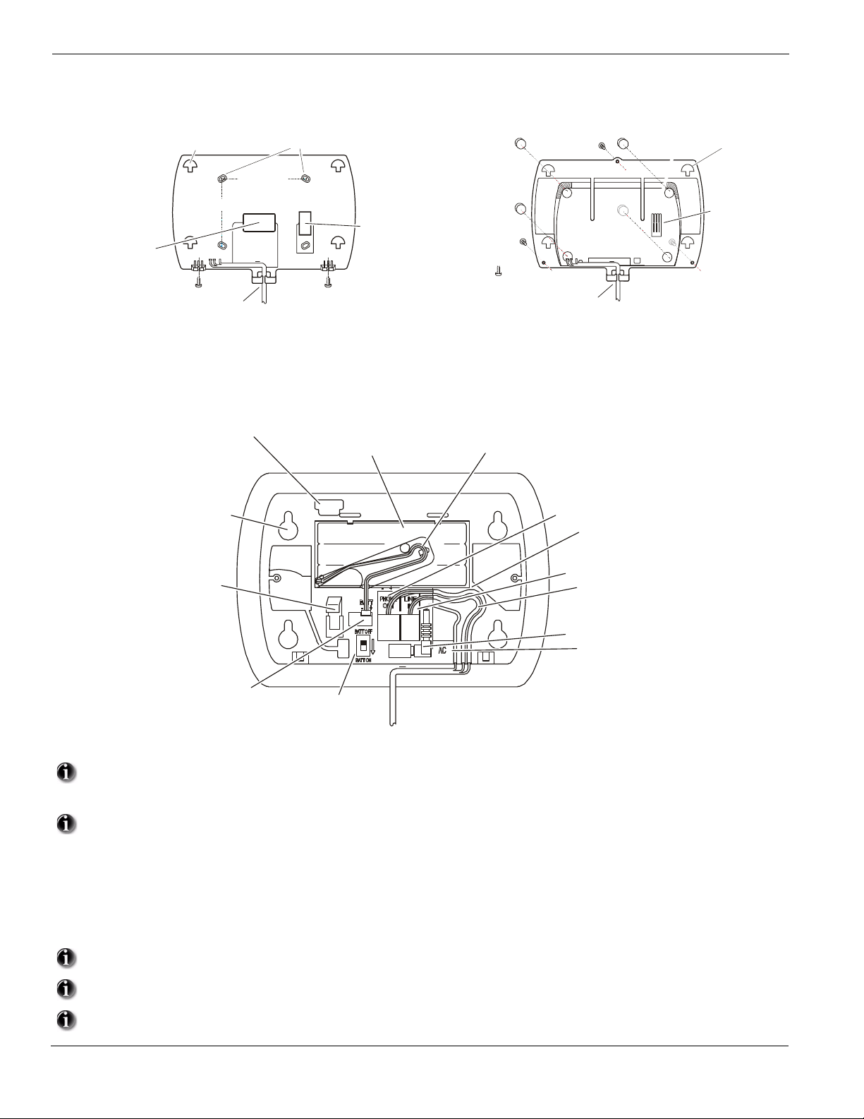
1.1 Installation:
2.5" (63 mm)
Route cables via
access hole or cable guide
as required
Ensure tamper switch
with mounting surface
3" (76 mm)
Mounting Hooks (4)
Rubber Feet ( 4)
Cover Screws (3)
Cable guide
Mounting Hooks (4)
Tamper
Switch
Battery Switch
Phon e Line Out
Phon e Line In
wiring channel guide
Battery
Connector
Battery (Ni MH)
7.2V , 1500 maH r
DC
Mounti ng Holes (4)
PC Link Head er
Battery Cable
Channel Guide & Clip
1
Select desired Location and Mounting Option
1
Wall Mount Installation
Mounting Holes (4)
makes secure contact
Desk Mount Installation
Tamper switch
contact surface
(a) Drill 4 holes in the desired location and insert drywall plugs.
(b) Route wiring through the access hole or cable guide as required.
(c) Secure backplate to wall using the 4 screws provided.
Connect wiring to the terminals indicated. See Section 1.2 Wiring for details.
2
Figure 1, Wiring Details
(a) Remove adhesive backing and install the rubber feet (4).
(b) Route wiring through the cable guide.
wiring channel guide
16.5Vac Connector
wiring channel guide
(mates with mounting hooks
on Wall or Desk mount backplate.
3
4.
5.
6.
7.
8.
9.
2
Do NOT apply power until wiring is completed.
Connect battery cable connector to the PC Board.
Ensure connector is oriented correctly.
Position Alarm System mounting holes over mounting hooks. Slide unit downward until unit snaps in place.
Secure Alarm System to wall or desk mount with the two screws provided.
Enroll devices. Enter [][8][Installer Code][898]. See Section 2, Wireless Device Enrollment.
If performing Template programming, enter [][8][Installer Code][899]. See Section 3, Template Programming.
Enter Advanced Programming if required. See Section 6, Advanced Programming.
Test System by violating zones and verifying successful transmission to the monitoring station.
See DLS Programming on page 9 for reprogramming an existing Installation.
AC Power must be present for the Alarm system to answer incoming calls from DLS.
After the initial installation 24 Hrs. is required to fully charge the standby battery.
Page 7
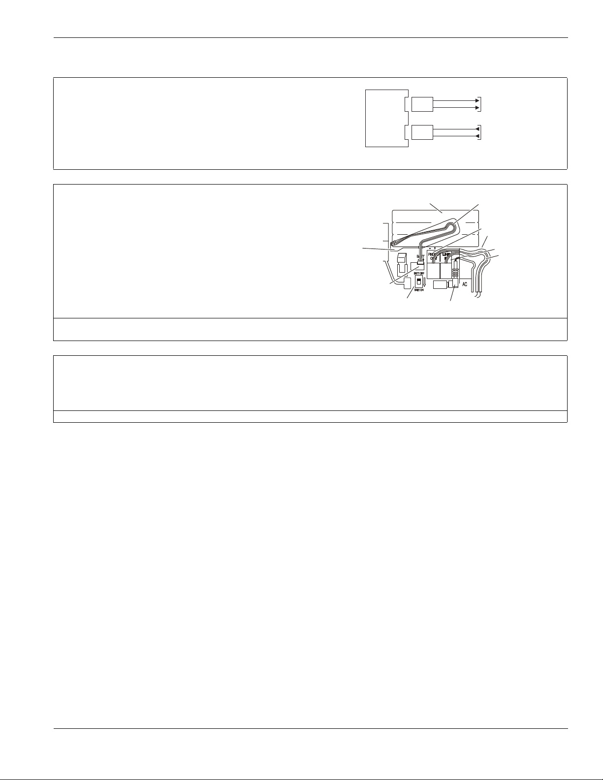
1.2 Wiring
RJ11
ALARM
SYSTEM
RJ11
In from
Telephone Company
Out to
Premise Telephone
Line Out
Line In
Battery Switch
Phone Line In
Wiring channel guide
Battery
Connector
Battery (Ni MH)
7.2VDC, 1500 maHr
Battery Cable
Channel Guide & Clip
Insert
Screwdriver
Here
1. Telephone Line Wiring
Connect Line IN and Line Out to RJ-11 Connectors as indicated.
Line In: For the Alarm System to seize the line in an emergency situation, Line
In must be connected directly to the incoming telephone line before connection
to additional devices.
Line Out: Connect Line out to the first telephone or device, wire additional
extensions in series.
Communication format is programmed in section [350].
Telephone Call Directions are programmed in section [351]-[376].
2. Battery Pack
A 1500 mA Hr Ni-Mh battery pack is included to provide 24 Hr standby power.
Battery Removal/Replacement
1. Set Battery Switch to OFF.
2. Gently disconnect battery connector from unit.
3. Insert a small flathead screwdriver in the slot on bottom left of battery.
4. Gently pry battery free of unit.
Dispose of battery in accordance with local regulations
5. Plug-in replacement battery connector. Observe correct polarity.
6. Route connector wiring through the battery clip and channel guide.
7. Position battery in the space provided with battery leads located at bottom
left hand corner of the enclosure.
8. Set Battery Switch to ON.
Phone Line Out
Wiring channel guide
AC right angle barrel plug
1.2 Wiring
NOTE: Battery life is 4-5 years under typical operating conditions. Replace Battery every 4-5 years. Battery capacity deteriorates with age and
number of charge/discharge cycles.
3. AC Wiring
AC Transformer Requirements:
Primary: 240V
Secondary: 16.5VAC/0.95 A 15.02VA
DSC recommends that the following transformer shall be used:
A41609AC (50Hz.) Right Angle Barrel Connector (supplied)
AC, 50Hz., 0.06 A
NOTE: Do not connect transformer to a receptacle controlled by a switch.
3
Page 8
Section 2: Wireless Device Enrollment
Before a wireless device can be recognized by the security system, it must be enrolled.
Devices that are not enrolled will be ignored by the system. See “Section [904]: Wireless Module Placement Test” on page 43.
Device Enrollment must be performed close to the alarm system.
Maximum signal strength is required to ensure that the correct device is being enrolled.
Pressing the # key at any time will return user to previous screen.
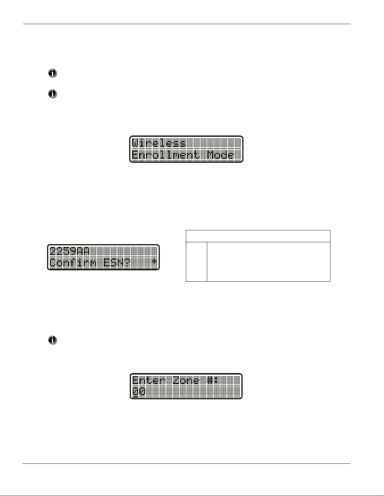
1. Enter Wireless Enrollment Mode
Enter [][8] [Installer Code] [898] on the system keypad.
2. Activate Wireless Device
- For FOBs & Panic Pendants - Press any button
- For PIRs, Smoke and Glass Break Detectors - Activate Tamper
- For Contact Switches - Close Contacts
3. Verify Device Electronic Serial Number (ESN)
When a device is activated the Alarm system will display the corresponding 6-digit ESN on the keypad.
Ve rify that the ESN displayed corresponds to the ESN on the device.
Note: The first digit of the ESN indicates the following:
2
denotes contact
3
denotes PIR/Glass Break Detector
4
denotes Smoke Detector
5
denotes Pendant
6&9
denotes FOB
4. Press [*] to confirm correct ESN, or press [#] to delete device if incorrect.
If the ESN displayed on keypad does NOT correspond to the ESN on the device being enrolled.
- Deactivate the wireless device
- Press the # key to repeat the enrollment process.
- Perform these steps until the correct ESN is displayed
If the device fails to enroll (i.e., incorrect ESN) attempt manual programming and testing of the device
before determining that the device is faulty . Maximum signal strength is required to ensure that the correct
device is being enrolled.
5. Enter Zone Number
After confirming that the device ESN is correct, the installer will be prompted to enter a zone number.
4
Page 9
Section 2: Wireless Device Enrollment
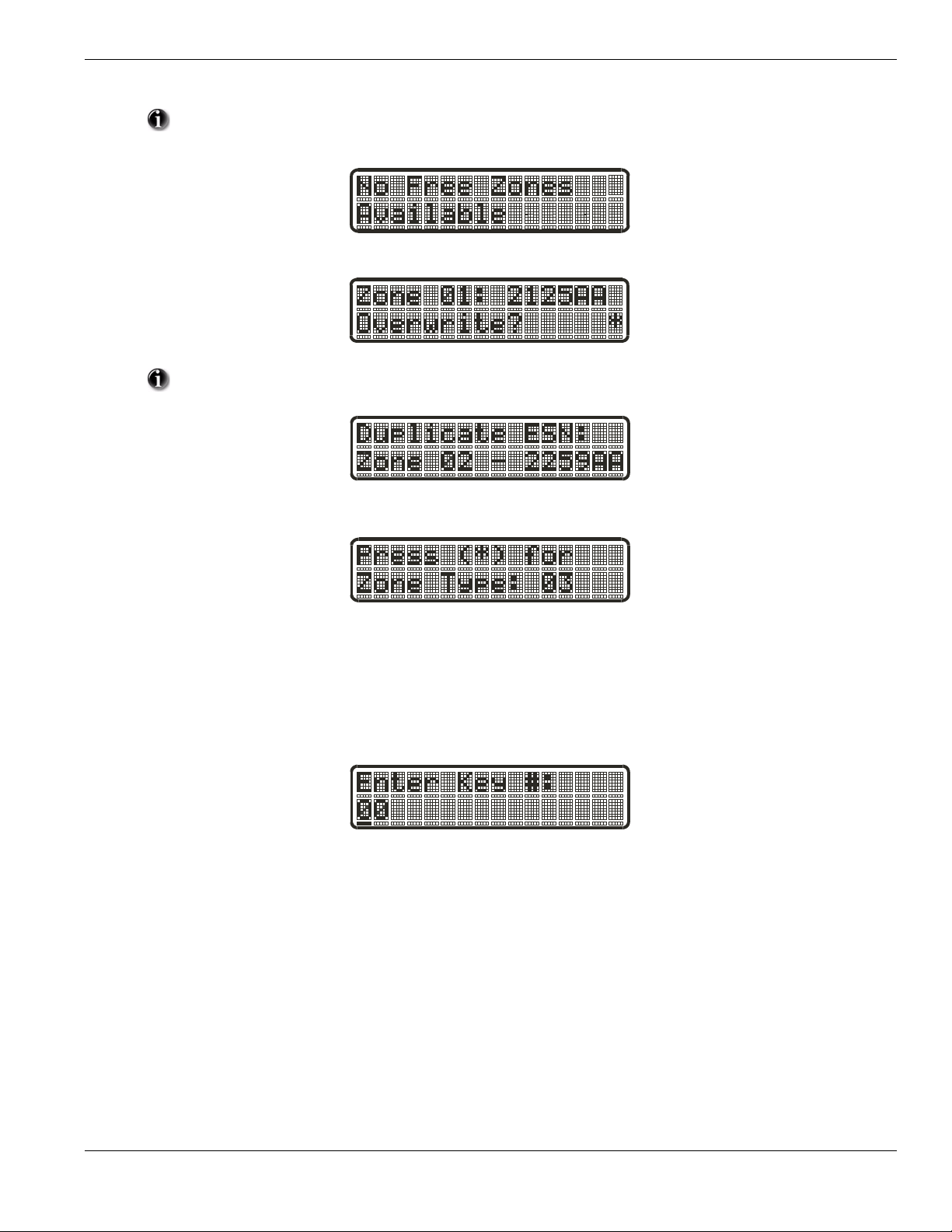
If the installer selects a zone that is currently in use, the installer will be prompted to overwrite the current
zone or select a new zone. If all zones are in use the installer will be prompted to overwrite the selected zone.
If the installer attempts to enroll a device already on the system, the keypad will briefly indicate that it is a
duplicate ESN.
Zone Dependant Devices (Detectors)
After the zone has been selected the keypad will display zone type 03. The Installer may enter an alternate zone type if required. When the zone
type has been selected the device will be enrolled.
Place wireless detectors in the desired locations and perform the wireless placement test. Reposition devices if necessary to achieve the required
signal strength.
For FOBs, the device is enrolled when the slot is selected. Zone type is not requested.
5
Page 10
Section 3: Template Programming
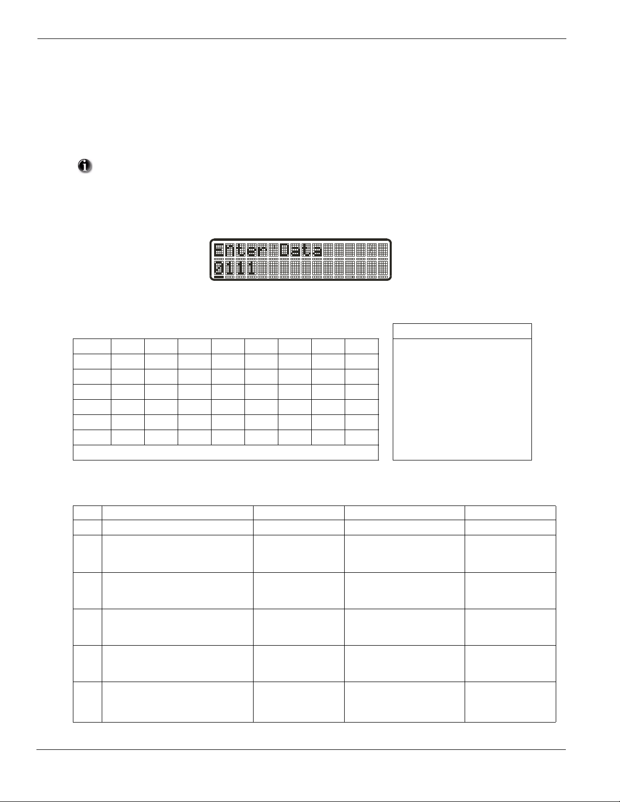
Template programming allows the Installer to quickly program the minimum functions required for basic operation. The installer is prompted to
enter a 4-digit code that selects predefined zone definitions, reporting code formats, Troubles & Restorals, and DLS setup (see Digit 1 - 4 tables
below). The Installer is then prompted to enter the Central Station Telephone Number & Account Code, DLS Access Code, Entry & Exit Delays
and Installer Code (see entry 5-9 below).
Selecting [][8] [Installer Code] [899] displays the default settings for the first 4 options below.
Once this section has been entered, the Installer ca nnot exit until all sections are completed.
Enter new data and/or Press # key to accept the displayed data and proceed to the next section.
Changing a single digit, then pressing the # key will advance to the next section but will not save the
changed data. Enter all 4 digits or scroll to the end of template programming and exit to save data.
STEP 1
• Digit 1 selects 1 of the following 6 options for Zone definitions for the first 8 zones. A ‘0’ in the digit 1 location indicates that the default set-
tings for the first 8 zones are in place unless overridden. See Section [001]-[002] on page 15 for defaults.
Zone Definitions (Options 1- 6)
Option Zn1 Zn2 Zn3 Zn4 Zn5 Zn6 Zn7 Zn8 1 Delay 1
1 13334444 2 Delay 2
2 133555588 3 Instant
3 133555587 4 Interior
4 11333333 5 Interior Stay/Away
5 13365555 6 Delayed Stay/Away
6 133655588 87 Delayed 24Hr. Fire (Wireless)
Refer to “Section [001]-[002] Zone Definitions” on page 32 for details 88 Standard 24 Hr. Fire (Wireless)
• Digit 2 selects 1 of the following 6 options for Reporting Codes
Opt# Phone Line 1 Programming Section Phone Line 2 Programming Section
Disabled [380] Opt 1 OFF Disabled
1
SIA automatic Reporting Codes enabled [350] 1st Phone # [04]
2
[380] Opt 1 ON
[381] Opt 3 OFF
Contact ID Reporting Codes enabled [350] 1st Phone # [03]
3
[380] Opt 1 ON
[381] Opt 7 OFF
SIA automatic Reporting Codes enabled [350] 1st Phone #[04]
4
[380] Opt 1 ON
[381] Opt 3 OFF
Contact ID Reporting Codes enabled [350] 1st Phone # [03]
5
[380] Opt 1 ON
[381] Opt 7 OFF
Contact ID Reporting Codes enabled [350] 1st Phone # [03]
6
[380] Opt 1 ON
[381] Opt 7 OFF
6
SIA Automatic Reporting Codes
Enabled
SIA Automatic Reporting Codes
Enabled
Residential Dial
Enabled
Residential Dial
Enabled
Contact ID Reporting Codes
Enabled
[350] 2nd Phone # [04]
[350] 2nd Phone # [04]
[381] Opt 3 OFF
[350] 2nd Phone # [06]
[350] 2nd Phone # [06]
[350] 2nd Phone # [03]
Page 11

• Digit 3 selects 1 of the 8 following options
Section 3: Template Programming
Option
Common
Group
Selected
Tro ubl es
Openings/
Closings
1
2
3
4
5
6
7
8
indicates included, Blank indicates default setting, indicates disabled
• Common Group - Sets all Reporting Codes to Automatic
Description Phone 1 Phone 2 Sections
Set all Reporting Codes to automatic [320] - [348] FF
Alarm/Restore call directions enabled
Zone
Restorals
[351][1] ON, [2] OFF
DLS/Installer
Lead In/Out
Tamper/Restore Call directions disabled
Opening/Closing Call directions disabled
Maintenance Call Directions enabled
Test Transmission Call directions disabled
[359][1] OFF, [2] OFF
[367][1] OFF, [2] OFF
[375][1] ON, [2] OFF
[376][1] OFF, [2] OFF
• Selected Troubles - Enables the following Troubles
Trouble [345] Alarms [346] Restoral
Battery FF FF
AC Failure 00 00
Fire Trouble FF FF
Aux PS FF FF
TLM XX 00
General System 00 00
FF = Communicate in automatic format, 00 = Disabled, XX = Not Transmitted
• Openings & Closings - Sets Residential Dial Reporting Codes for all openings and closings
Users CLOSINGS, Residential Dial Reporting codes Section
1-8 5152535455565758[339]
9-16 61 62 63 64 65 66 67 68 [339]
40 99 FF FF FF FF XX XX XX [341]
7
Page 12

Users OPENINGS, Residential Dial Reporting codes Section
1-8 1112131415161718[342]
9-16 21 22 23 24 25 26 27 28 [342]
40 98 FF XX XX XX XX XX XX [344]
Enable Opening/Closings call directions for Phone 2
FF = Communicates in Automatic Mode, XX = Not Used
[367] Opt 2 ON
• Installer Lead-in/Lead-out and DLS Lead-in/Lead-out
DLS Lead In
Sect [347] Opt 4
DLS Lead Out
Sect [347] Opt 5
Disabled for all Template Options except Option 8
Installer Lead Out
Sect [347] Opt 11
Installer Lead In
Sect [347] Opt 12
Digit 4 indicates/selects 1 of the 3 following DLS Connections
Option
1
2
3
Double Call
Sect [401] Opt 1
Call Back
Sect [401] Opt 3
#Rings
Sect [406] Opt 3
0
8
8
After the 4th digit is entered you will be prompted to enter the following Data. Refer to Section 8 for additional programming functions.
Step 2 Central Station Telephone Number
Enter 32 Character Telephone number - See “Section [301]-[303] Communication Telephone Numbers” on
page 37 for details.
Step 3 Central Station Account Code
Enter the 6-digit code - See “Section [310] System Account Number” on page 37 for details.
Step 4 DLS Access Code
Enter the 6-digit code - See “Section [403] Downloading Access Code” on page 40 for details.
Step 5 Entry Delay1, Exit Delay
Enter Entry Delay1, Exit Delay - See “Section [005] System Times” on page 33 for details.
Step 6 Installer Code
Enter a 4 or 6-digit entry depending on setting of Section [701] Opt 5 - See “Section [006] Installer Code”
on page 33 for details.
8
Page 13

Section 4: DLS Programming
Section 4: DLS Programming
4.1 Local Programming with PC-Link
Follow the steps below in the sequence indicated to set up local programming using DLS:
New installations (refer to Section 1.1 Installation: on page 2)
1. Remove the Alarm System from the Wall Mount or Desk Mount.
2. Connect the AC Wiring.
In a new installation the backup battery requires 24 Hrs. charging. AC Power is required for PC-Link Programming until
battery is charged.
3. Connect the PC-Link cable between the computer (with DLS Software installed) and the header pins on the alarm system.
Connecting the DLS PC to the system will automatically initiate the connection.
4. When programming has been completed, remove the PC-Link cable
5. Complete the installation.
4.2 Remote Programming (via telephone line)
Refer to Section “[401] Downloading Options” on page 24 and page 39 for details.
AC Power must be present for the alarm system to answer incoming calls from DLS.
9
Page 14

Section 5: Operation
The LCD keypad displays the description and status indicator lights represent alarm functions and status. This section describes basic keypad
commands. Refer to the User Guide for detailed descriptions of all keypad commands.
Press the [#] key to reset the keypad if an error has been made entering user codes or keypad commands.
5.1 – Away Arming
The Ready light must be ON to arm the system. If the Ready light is OFF, ensure all protected doors and windows are secure or bypassed. T o arm
the system in the Away mode, either press and hold the Away function button for 2 seconds or enter a valid user code and leave the premises
through a door programmed as Delay. Upon pressing a function key or entering an access co de, the Armed light will turn ON. If the Audible Exit
Delay option is enabled, the keypad will beep once every second during the exit delay (and three times a second during the last 10 seconds) to
alert the user to leave. The Ready light will turn off when the Exit Delay ends.
5.2 – Stay Arming
The Ready light must be ON to arm the system. If the Ready light is OFF ensure all protected doors and windows are secure or bypassed. To arm
the system in the Stay mode, either press and hold the Stay function button for 2 seconds or enter a valid user code and stay within the premises
(do NOT violate a door programmed as Delay). Upon pressing a function key or entering an access code, the Armed light will turn ON. If the
Stay function button is used, the keypad will not beep during the exit delay to avoid annoying the person staying in the premises. If a user code
was used, the keypad will beep if the Audible Exit Delay option is enabled. The Ready light will turn off when the Exit Delay ends.
Zones must be programmed with Zone definitions: 05 Interior Stay/Away, 06 Delay Stay/Away, or 32
Instant Stay /Away for this function to work.
5.3 – Disarming
The user must enter through a door programmed as Delay. Upon entering, the keypad will emit a steady tone (and emit a pulsing tone during the
last 10 seconds of entry delay) to alert the user to disarm the system. Enter a valid user code to disarm the system. If an alarm occurred while the
panel was armed, the keypad will display ‘Alarm in Memory’. Press the [#] key to return the keypad to the Ready state.
5.4 – [] Commands
The following is a list of the [] commands available and a description of each:
[][1] Bypass (disarmed state)/Reactivate Stay/Away Zones (armed state)
[][2] Display Trouble Conditions
[][3] Display Alarm Memory
[][4] Door Chime Enable/Disable
[][5] User Code Programming
[][6] User Commands
[][7][x] Command Functions 1 – 2
[][8] Installer Programming
[][9][code] No-Entry Arming
[][0] Quick Arm (disarmed state)/Quick Exit (armed state)
[][1] – Bypass/Re-activate Stay/Away and Night Zones
Press [][1] to enter the bypass mode. If the Code Required for Bypass option is enabled, enter a valid user code. The keypad will display ‘Scroll
to Bypass Zones’. The keypad will display the programmed zone labels for the zones and include the letter ‘O’ in the bottom, right corner if the
zone is violated or the letter ‘B’ if the zone is bypassed. Scroll to the appropriate zone and press the [] key to change the bypass status (or enter
the 2-digit zone number). Once the correct zones are bypassed, press [#] to exit.
Additional Bypass Commands:
Bypass Recall: Press [99]. The keypad will recall the last group of zones that were bypassed.
Clear Bypass: Press [00]. The keypad will clear the bypass on all zones.
Save Bypass: Press [95]. The keypad will save which zones are manually bypassed.
Recall Save: Press [91]. The keypad will recall the bypassed zones that were saved.
Re-activate Stay/Away and Night Zones:
Press [][1] when the system is armed in the Stay mode to change the armed status to Away mode or Night mode. The system will add the Stay/
Away zones back into the system after the exit delay time expires.
10
If any zones are programmed as Night Zones (zone definition 37) pressing [][1] will activate the Night
mode instead of Away mode. Only Night Zones will be bypassed.
Page 15

Section 5: Operation
[][2] – Trouble Display
Refer to Section 9: Testing & Troubleshooting, for troubleshooting assistance and a detailed description of all trouble conditions.
[][3] – Alarm Memory Display
Pressing the scroll <> keys will display an “Alarms in Memory” message if an alarm occurred during the last armed period. Pressing [][3] will
display the message “Scroll to view Alarms”. Scrolling will display the zones that went into alarm. To clear the Memory, arm then disarm the
system.
[][4] – Door Chime Enable/Disable
Press [][4]. The keypad will emit 3 rapid beeps to indicate that the door chime feature is now enabled and a steady 2-second tone if it is now disabled. The same function can be performed by pressing and holding the Chime function button for 2 seconds.
[][5] – Program User Codes
The following table identifies available user codes:
Code Type Function
[01] – [16]
[40]
General User Codes
Master Code
Arm, disarm, attribute functions
All functions, arm, disarm, program user codes
Programming User Codes:
Press [][5] followed by the Master Code. The keypad will display the first user (user 01) and include the letter ‘P’ if the user code is pro-
grammed. Scroll to the appropriate user and press the [] key to program the user (or enter the 2-digit user number). Enter a new 4 or 6-digit user
code or press [] to delete the user code. After the user code is programmed or deleted, scroll to another user or press [#] to exit.
Programming User Attributes:
Press [][5] followed by the Master Code or Supervisor Code. Press [9] followed by the 2-digit user to change to the user attributes.
[1] Supervisor’s Code
This attribute makes the code valid when entering the [][5] User Code Programming section and [][6] User
Functions. Note, these codes can only program codes which have equal or lesser attributes. This attribute will also
allow this user to create bypass groups if an access code is required to enter into [][1] Bypassing.
[2] Duress Code
Duress codes are standard user codes that will transmit the Duress Alarm Reporting Code whenever the code is
entered to perform any function on the system.
[3] User can manually bypass zones if Bypassing requires an access code.
[4]-[6] Future Use
[7] The panel will squawk the bell output when the user arms or disarms when in Away Armed mode.
[8] One-time Use Code
The One-time-use Code allows unlimited arming but only permits a single disarming once a day.
The Disarm function is restored at midnight.
To change the user attributes, press the number corresponding to the attribute or scroll to the desired attribute and press []. When the correct
attributes are assigned to the user, press [#] to exit. To change the user attributes for another user, press [9] followed by the 2-digit user number.
When finished, press [#] to exit.
These attributes affect the operation of wireless keys.
Wireless key numbers (01-16) correspond with User access codes (01-16).
Duress codes are not valid when entering [*][5], [*][6] or [*][8] sections and will transmit a duress alarm.
Duplicate codes and codes that are +/- 1 of an existing code can not be programmed.
11
Page 16

[][6] – User Functions
Press [][6] followed by the Master Code, then press the number corresponding to the following functions or scroll to the desired option, then
press [].
[1] Program Time and Date: Enter the time and date using the following format [HH:MM] [MM/DD/YY]. Program the time using
military standard (e.g., 8:00 pm = 20:00 hours).
[2]-[3] Future Use
[4] System Test: The panel will activate the keypad buzzer, LCD pixels and all keypad status lights for 2 seconds followed by 2
seconds of full volume alarm, perform the battery test, then transmit a reporting code to the central station (if programmed).
[5] Enable DLS: The panel will temporarily enable DLS double-call for 6 hours.
[6] User Initiated DLS: The panel will attempt to call the DLS computer.
[7] Future Use
[8] User Walk Test Mode: The panel will switch into User Walk Test Mode. The panel will display the base mode menu.
Additional Keypad Functions:
When scrolling through the list of available functions, the following additional functions are available:
Event Buffer: Used to view the 128-event panel buffer
Brightness Control: Used to adjust the display backlighting level for optimal viewing
Contrast Control: Used to adjust the display contrast level for optimal viewing
Buzzer Control: Used to adjust the keypad buzzer tone for optimal sound
[][7][x] – Command Outputs (1&2)
Press [][7][x]. If the Command Output Code Required option is enabled, enter a valid user code. The panel will activate any PGM output
assigned to the command output.
[][8] – Installer Programming
Press [][8][Installer Code] to enter Installer Programming. Installer programming allows the installer to program all system functions.
Refer to the Section 6: Advanced Programming for details.
[][9][User Code] – No-Entry Arming
Press [][9] followed by a valid user code. The system will arm in the Stay mode and after the exit delay expires, it will remove entry delay. All
zones programmed as Delay will function like Instant zones. The system will flash the Armed light to indicate that the system is armed with no
entry delay.
[][0] – Quick Arm/Quick Exit
Quick Arm: When disarmed, press [][0] to arm the system. The system will arm as if a valid user code was entered.
Quick Exit: When armed, press [
ing the following 2 minute time period without changing the status of the system.
][0] to activate Quick Exit. The system will allow a single zone programmed as Delay to be violated once dur-
5.5 Function Keys
The keypad has 5 programmable one-touch function keys located in a column down the right-side of the keypad. These keys can also be activated
by pressing and holding number [1] through [5] respectively for 2 seconds. The default for these keys are as follows:
[1] Stay Arm [4] Bypass
[2] Away Arm [5] Quick Exit
[3] Chime Enable/Disable
5.6 Language Selection
The keypad can be programmed to display messages and labels in different languages. Perform the following when in ‘Ready to Arm’ mode or
base Installer programming menu:
[1] Press and hold both scroll keys [< >] simultaneously until language options are displayed.
[2] Scroll to the desired language using the scroll keys [< >].
[3] Press [
] to select the desired language.
12
Page 17
Section 6: Advanced Programming
Section 6: Advanced Programming
This section provides the information necessary to program all required features for a basic system as well as common applications.
6.1 How to Program
DSC recommends filling in the Programming Worksheet with the required programming information before programming the system. This will
reduce the time required to program and will help eliminate errors.
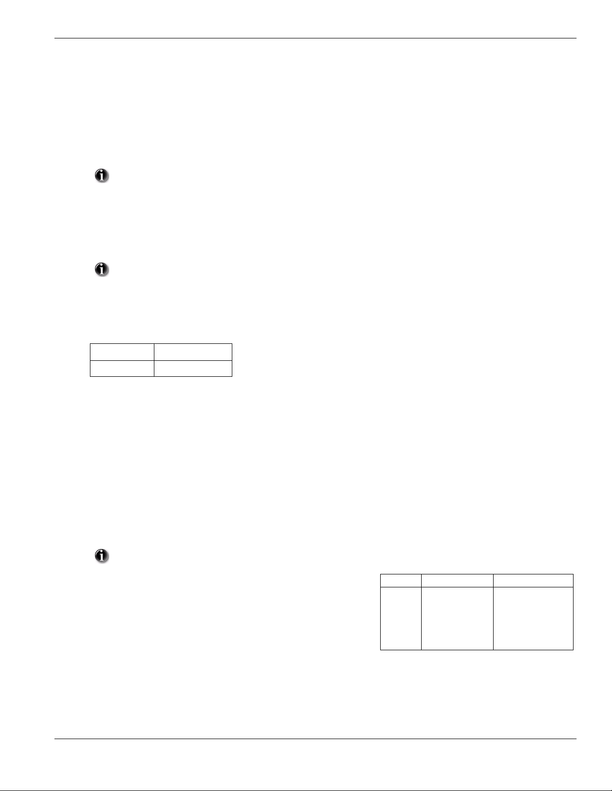
To e nter Installer Progra mming press [][8] [Installer Code]. The LCD keypad will display ‘Enter Se ction’ . An error to ne indicate s the installer
code entered is incorrect. Press [#] to clear any key presses and try again.
The default Installer Code is .
The Armed and Ready lights indicate programming status:
Armed Light ON Panel waiting for 3-digit section number
Ready Light ON Panel waiting for data to be entered
Ready Light FLASHING Panel waiting for HEX data to be entered
You cannot enter installer programming while the system is armed or in alarm.
6.2 Programming Toggle Options
Enter the 3-digit programming section number:
• The Armed light will turn OFF and the Ready light will turn ON
• The keypad will display which toggle options are ON or OFF according to the table below
Option ON Option OFF
# Displayed Dash [-] Displayed
• To toggle an option ON or OFF, press the corresponding number on the keypad. The display will change accordingly
• When all the toggle options are configured correctly, press the [#] key to exit the program section
• The Ready light will turn OFF, the Armed light will turn ON and the LCD will display “Enter Section”
6.3 Programming Decimal and Hexadecimal (HEX) Data
• Enter the 3-digit programming section number
• The Armed light will turn OFF and The Ready light will turn ON
• Enter the data written in the boxes
For sections that require multiple 2 or 3 digit numbers, the keypad will double-beep after each 2 or 3 digit entry and move to the next item in the
list. After the last digit in the section is entered, the keypad will beep rapidly 5 times and exit the program section. The Ready light will turn OFF,
the Armed light will turn ON and the LCD will display “Enter Section”.
For sections that do not require data for every box (such as phone numbers) press the [#] key to exit the program section afte r ente ring all the
required data. The Ready light will turn OFF , the Armed light will turn ON and the LCD will display “Enter Section”.
At any time the [#] can be pressed to exit any program section. All changes (excluding Template Programming) will be saved.
In addition to the standard digits 0-9, HEX digits and special dialer functions can also be programmed.
Value Enter Telephone Dialer
To enter a HEX digit, press the [] key to begin HEX programming. The Ready light
will FLASH. Press the number corresponding to the HEX digit required. The Ready
light will continue to FLASH. Press [
ming. The Ready light will turn ON.
] again to return to normal decimal program-
HEX [A]
HEX [B]
HEX [C]
HEX [D]
HEX [E]
HEX [F]
Press [][1][]
Press [][2][]
Press [][3][]
Press [][4][]
Press [][5][]
Press [][6][]
Not Supported
Simulated [] key
Simulated [#] key
Dial tone search
Two second pause
Not Supported
6.4 How to Exit Installer Programming:
To exit installer programming, press the [#] key when the panel is waiting for a 3-digit section number (the Armed light is ON). The LCD will
display the user menu.
6.5 Viewing Programming
The keypad will immediately display all the information programmed when a programming section is entered. Use the arrow keys (< >) to sc roll
through the data being displayed. Scroll past the end of the data displayed, or press the [#] key to exit the section.
13
Page 18

Section 7: Programming Work Sheets
7.1 Index to Programming Work Sheets and Descriptions
Programming Option..............................................................PWS/Desc.
Programming Option (cont.).................................................. PWS/Desc.
[000] Keypad Function Key Programming.......................................15/32
[001]-[002] Zone Definitions............................................................ 15/32
[005] System Times ..........................................................................16/33
[006] Installer's Code ........................................................................16/33
[007] Master Code ............................................................................ 16/33
[009] I/O Programming..................................................................... 16/33
[012] Keypad Lockout Options.......................................... .. .............16/33
[013] First System Options ...............................................................16/34
[014] Second System Options........................................................... 17/34
[015] Third System Options.............................................................. 17/34
[016] Fourth System Options ............................................................17/35
[023] Tenth System Options.............................................................. 17/35
[030] Zone Loop Response Options .................................................18/36
[101]-[134] Zone Attributes.............................................................. 18/36
[168] Set Clock Forward (Daylight Saving Time)............................ 19/36
[169] Set Clock Back (Standard Time) ............................................. 19/37
[170] PGM Output Timer..................................................................19/37
[176] Cross Zone/Police Code T imer...............................................19/37
[190] No Activity Arming Pre-Alert Timer......................................19/37
[191] No Activity Arming Timer...................................................... 19/37
[202]-[206] Zone Assignments ......................................................... 19/37
[301] First Telephone Number..........................................................19/37
[302] Second Telephone Number................................................. .. ...19/37
[303] Third Telephone Number ........................................................ 19/37
[304] Call Waiting Cancel String......................................................19/37
[310] System Account Code .............................................................19/37
[320]-[322] Alarm Reporting Codes................................................. 20/37
[324]-[326] Alarm/Restoral Reporting Codes..................................20/37
[328] Misc. Alarm Reporting Codes.................................................20/37
[329] Priority Alarm And Restoral Reporting Codes .......................20/37
[330]-[332] Tamper Reporting Codes...............................................21/37
[334]-[336] Tamper Restoral Reporting Codes................................. 21/37
[338] Misc. Tamper Reporting Codes...............................................21/37
[339] Closing (Arming) Reporting Codes (Access Codes) ..............21/37
[341] Misc. Closing (Arming) Reporting Codes ..............................21/37
[342] Opening (Disarming) Reporting Codes (Access Codes).........21/37
[344] Misc. Opening (Disarming) Reporting Codes.........................21/37
[345] Maintenance Alarm Reporting Codes..................................... 22/37
[346] Maintenance Restoral Reporting Codes.................................. 22/37
[347] Misc. Maintenance Reporting Codes ......................................22/37
[348] Test Transmission Reporting Codes........................................22/37
[350] Communicator Format Options...............................................22/38
[351] Alarm/Restore Comm. Call Directions...................................22/38
[359] Tamper/Restore Comm. Call Directions .................................22/38
[367] Opening/Closing Comm. Call Directions ...............................22/38
[375] System Maintenance Comm. Call Directions ......................... 23/38
[376] System Test Transmission Comm. Call Directions.................23/38
[377] Communication Variables ....................................................... 23/38
[378] Test Transmission Time of Day............................................... 23/38
[380] First Communicator Options................................................... 23/38
[381] Second Communicator Options ..............................................24/39
[382] Third Communicator Options .................................................24/39
[401] Downloading Options .............................................................24/39
[402] DLS Downloading Telephone Number.............. .....................24/40
[403] Downloading Access Code .....................................................24/40
[404] Panel Identification Code................................... .....................24/40
[405] Double Call Timer...................................................................25/40
[406] Number of Rings to Answer On..............................................25/40
[499] Initiate PC Link Downloading ................................................25/40
[501]-[502] PGM Output Attributes.................................................25/40
[700] Automatic Clock Adjust..........................................................26/41
[701] First International Options ......................................................26/41
[702] Second International Options..................................................26/42
[703] Delay Between Dialing Attempts............................................26/42
[804] Wireless Programming............................................................27/42
[01]-[32] Wireless Zone Programming....................................27/42
[41]-[56] Wireless Key Programming .....................................27/42
[60]-[76] Wireless Key Function Key Programming............... 27/42
[81] Wireless Supervisory Window ......................................... 27/42
[82]-[85] Zone Transmitter Supervision..................................28/42
[90] General Wireless Options.................................................28/42
[898] Wireless Device Enrollment....................................................28/43
[899] Template Programming.................................... .... ...................28/43
[900] Panel Version Displayed..........................................................28/43
[904] Wireless Module Placement Test ............................................ 28/43
[990] Installer Lockout Enable .................................................. .. ..... 28/43
[991] Installer Lockout Disable ........................................................28/43
[996] Restore Wireless Device Default Programming......................28/43
[998] Restore Control Panel Default Programming..........................28/43
[999] Restore System Default Programming............................. .. ..... 28/43
Local Keypad Programming................................. .........................29/44
[001]-[034] Zone Label Programming..............................................29/44
[065] Fire Alarm Label.....................................................................30/44
[066] Fail to Arm Event Message.....................................................30/44
[067] Alarm When Armed Event Message.......................................30/44
[068] Command Output #1 Label.....................................................30/44
[069] Command Output #2 Label.....................................................30/44
[074] First Keypad Options ..............................................................31/45
[075] Second Keypad Options..........................................................31/45
[076] Third Keypad Options.................... .........................................31/46
[077] Programmed LCD Message ....................................................31/46
[078] Programmed LCD Message Duration.....................................31/46
[201-[234] Door Chime Options................................. ......................31/46
[996] Reset Programmable Labels to Factory Defaults....................31/46
14
Page 19

7.2 Programming Worksheets
Keypad and Function Key Programming
See “Local Keypad Programming” on page 29. for additional options.
[000] Function Key Programming
[1] Function Key 1 Assignment
[2] Function Key 2 Assignment
[3] Function Key 3 Assignment
[4] Function Key 4 Assignment
[5] Function Key 5 Assignment
Function Key Options:
00 Null Key
Future Use
01
Future Use
02
Stay Arm
03
Away Arm
04
[][9] No Entry Arm
05
06 [][4] Chime On / Off
Future Use
07
[][1] Bypass Mode
08
09 Future Use *27 Disarm
10 Future use *29 [A]uxilliary Alarm
11 Future use *30 [P]anic
12 Future Use
13 [][7][1] Command Output #1 * Applies to Key Fobs only
14 [][7][2] Command Output #2 See Section [804] Subsection [61]-[76]
15 For Future Use
16 [][0] Quick Exit
17 [][1] Reactivate Stay/Away Zones
7.2 Programming Worksheets
Key 1 Key 2 Key 3 Key 4 Key 5
Keypad Defaults
03 ___ 04 ___ 06 ___ 08 ___ 16 ___
[001]-[002] Zone Definitions
00 Null Zone (Not Used) 13 24 Hour Gas* 25 Interior Delay*
01 Delay 1* 14 24 Hour Heat* 26 24 Hour Non-alarm
02 Delay 2* 15 24 Hour Medical* 27-31 Future Use
03 Instant* 16 24 Hour Panic* 32 Instant Stay/Away*
04 Interior* 17 24 Hour Emergency* 33-35 Future Use
05 Interior, Stay/Away* 18 Future Use 36 24 Hr. Non-latching Tamper
06 Delay, Stay/Away* 19 24 Hour Water* 37 Night Zone*
07-08 Future Use 20 24 Hour Freeze* 87 Delayed 24 Hr. Fire (Wireless)**
09 24 Hour Supervisory (Hardwired) 21 Future Use 88 Standard 24 Hr. Fire (Wireless)**
10 24 Hour Supervisory Buzzer* 22 Momentary Keyswitch Arm* 89 Auto-verified 24 Hr. Fire (Wireless)**
11 24 Hour Burglary* 23 Maintained Keyswitch Arm (Hardwired)*
12 Future Use 24 Future Use
*For burglary applications only ** For residential fire applications only
Section Zone Default Section Zone Default Section Zone Default Section Zone Default
[001]
01 01
02 03
03 03
04 03
05 04
06 04
07 04
08 04
I_____I_____I
I_____I_____I
I_____I_____I
I_____I_____I
I_____I_____I
I_____I_____I
I_____I_____I
I_____I_____I
[001]
09 00
10 00
11 00
12 00
13 00
14 00
15 00
16 00
I_____I_____I
I_____I_____I
I_____I_____I
I_____I_____I
I_____I_____I
I_____I_____I
I_____I_____I
I_____I_____I
[002]
17 00
18 00
19 00
20 00
21 00
22 00
23 00
24 00
I_____I_____I
I_____I_____I
I_____I_____I
I_____I_____I
I_____I_____I
I_____I_____I
I_____I_____I
I_____I_____I
[002]
25 00
26 00
27 00
28 00
29 00
30 00
31 00
32 00
I_____I_____I
I_____I_____I
I_____I_____I
I_____I_____I
I_____I_____I
I_____I_____I
I_____I_____I
I_____I_____I
15
Page 20

[005] System Times
Valid entries for Entry Delay are between 030-255.
030
045
060
005
I___I___I___I Entry Delay 1 Valid entries are 001 - 255 seconds, 000 also sets time to 255 seconds
I___I___I___I Entry Delay 2 Valid entries are 001 - 255 seconds, 000 also sets time to 255 seconds
I___I___I___I Exit Delay Valid entries are 001 - 255 seconds, 000 also sets time to 255 seconds
I___I___I___I Bell Cut-off Valid entries are 001 - 255 minutes, 000 also sets time to 1 minute
[006] Installer’s Code [007] Master Code
Default Default
5555
I_______I_______I_______I_______I 1234 I_______I_______I_______I_______I
Programmable Output Options
00 Null PGM (Not Used)
01 Residential Burglary and Fire Bell Output
02-04 Future Use
05 System Armed Status
06 Ready To Arm
07 Keypad Buzzer Follower
08 Courtesy Pulse
09 System Trouble Output (with Trouble Options)
[009] I/O Programming
Program Zone Definition Attributes in Sections [133-134], Program PGM Option Attributes in sections [501] - [502].
Default
10
01
I_______I_______I I/O Type (Zone 33, PGM 1) Enter Zone Definition or PGM Definition
I_______I_______I I/O Type (Zone 34, PGM 2) Enter Zone Definition or PGM Definition
[012] Keypad Lockout Options
10 System Event Output (with Event Options)
11 System Tamper (all sources: zones, keypad)
12 TLM and Alarm
13-16 Future Use
17 Away Armed Status
18 Stay Armed Status
19 Command Output #1 ([
20 Command Output #2 ([
][7][1])
][7][2])
If Keypad Lockout is active, the panel cannot be disarmed with a keyswitch.
Default
000
000
I_______I_______I______I Number of Invalid Codes Before Lockout (Valid entries are 000-255)
I_______I_______I______I Lockout Duration (in minutes) (Valid entries are 000-255)
[013] First System Options
Opt Def. ON OFF
1
2
3-5
6
7
8
9
9
9
Hardwired Zone 33 Input Enabled
Hardwired Zone 34 Input Enabled
Future Use
Audible Exit Fault Enabled
Event Buffer follows Swinger Shutdown
Temporal Three Fire Signal Enabled
PGM1 Output Enabled
PGM2 Output Enabled
9
9
Audible Exit Fault Disabled
Event Buffer Logs Past Shutdown
Standard Pulsed Fire Signal
9
16
Page 21

[014] Second System Options
Opt Def. ON OFF
1
2
3
9
4
5
6
9
7
8
[015] Third System Options
Opt Def. ON OFF
1
9
2
3
4
9
5
6
7
9
8
Arm/Disarm Bell Squawk Enabled
Future Use
RF Jam Log After 5 Minutes
Aux Boost Enabled
Future Use
Audible Exit With Urgency
Future Use
Fire Bell is Continuous
[F] Key Enabled
[P] Key Audible (Bell/Beeps)
Quick Exit Enabled
Quick Arming Enabled ([][0] and Function Keys)
Code Required for Bypassing
Master Code not Changeable
TLM Enabled
System Tamper Enabled
Arm/Disarm Bell Squawk Disabled
9
9
RF Jam Logs After 20 seconds
Aux Boost Disabled
9
9
Silent Exit Delay
9
Fire Bell Follows Bell Cut-off
9
[F] Key Disabled
[P] Key Silent
9
Quick Exit Disabled
9
Quick Arming Disabled (Function Key Requires Code)
No Code Required
9
Master Code Changeable
9
TLM Disabled
System Tamper Disabled
9
7.2 Programming Worksheets
[016] Fourth System Options
Opt Def. ON OFF
1
2
9
3
4
5
9
6
9
7
8
9
[023] Tenth System Options
Opt Def. ON OFF
1
2
3
4
5
9
6
9
7
8
Cross Zoning Enabled
Exit Delay Restart Enabled (required for CP-01)
Blank Keypad When Not Used
Code Required to Remove Keypad Blanking
Keypad Backlighting Enabled
ID WKEY Not required for Disarming
Bypass Status Displayed While Armed
Daylight Saving Time Enabled
[F] Key Beeps Only
Future Use
Test Transmission while Armed Only
Test Transmission Counter in Hours
Switching from Away to Stay Disabled
Future Use
Trouble beeps are Silent
Keyswitch Arms in Away Mode
Police Code enabled
9
Exit Delay Restart Disabled
Keypad Always Active
9
No Code Required
9
Keypad Backlighting Disabled
ID WKEY Required for Disarming
Bypass Status Not Displayed While Armed
9
Daylight Saving Time Disabled
[F] Key Beeps and Sounds Bell
9
9
Test Transmission while Armed/Disarmed
9
Test Transmission Counter in Days
9
Away to Stay Toggle Option Permitted
Trouble Beeps Sound Every 10 seconds
9
Keyswitch Arms in Stay or Away Mode
9
17
Page 22

[030] Zone Loop Response Options
Opt Def. ON OFF
1
2
3-8
Zone 33 is Fast Loop Response
Zone 34 is Fast Loop Response
Future Use
Zone 33 is Normal Loop Response
9
Zone 34 is Normal Loop Response
9
9
[101]-[134] Zone Attributes: Options 10-13 are reserved for Future Use.
Zone Attribute Defaults
Attribute: 1 234 56 7 8 9 141516
ON Audible Steady Chime Bypass Force* Swing Tx. Delay Cross Zn
OFF Silent Pulsed No No No No No No
Zone Type:
00 Null Zone OFF OFF OFF OFF OFF OFF OFF OFF
01 Delay 1 ON ONONON ONON OFF OFF
02 Delay 2 ON ONONON ONON OFF OFF
03 Instant ON ONONONOFFON OFF OFF
04 Interior ON ON OFF ON OFF ON OFF OFF
05 Interior Stay/Away ON ON OFF ON ON ON OFF OFF
06 Delayed Stay/Away ON ON OFF ON ON ON OFF OFF
07 Future Use OFF OFF OFF OFF OFF OFF OFF OFF
08 Future Use OFF OFF OFF OFF OFF OFF OFF OFF
09 24hr Superv. (Hardwired) OFF ON OFF OFF ON ON OFF OFF
10 24hr Superv. Buzzer OFF ON OFF ON OFF ON OFF OFF
11 24hr Burglary ON ON OFF ON OFF ON OFF OFF
12 Future Use OFF OFF OFF OFF OFF OFF OFF OFF
13 24hr Gas ON OFF OFF OFF OFF ON OFF OFF
14 24hr Heat ON OFF OFF OFF OFF ON OFF OFF
15 24hr Medical ON ON OFF OFF OFF ON OFF OFF
16 24hr Panic ON ON OFF OFF OFF ON OFF OFF
17 24hr Emergency ON ON OFF OFF OFF ON OFF OFF
18 Future Use OFF OFF OFF OFF OFF OFF OFF OFF
19 24hr Water ON ON OFF OFF OFF ON OFF OFF
20 24hr Freeze ON ON OFF OFF OFF ON OFF OFF
21 Future Use OFF OFF OFF OFF OFF OFF OFF OFF
22 Momentary Keyswitch Arm
23 Maintained Keyswitch (Hardwired)
24 Future Use OFF OFF OFF OFF OFF OFF OFF OFF
25 Interior Delay ON ON OFF ON OFF OFF OFF OFF
26 24hr Non-alarm OFF OFF OFF OFF ON ON OFF OFF
27-31 Future Use OFF OFF OFF OFF OFF OFF OFF OFF
32 Instant Stay/Away ON ON OFF ON OFF ON OFF OFF
33 Future Use OFF OFF OFF OFF OFF OFF OFF OFF
34 Future Use OFF OFF OFF OFF OFF OFF OFF OFF
35 Future Use OFF OFF OFF OFF OFF OFF OFF OFF
36 24hr Non-latching Tamper OFF ON OFF OFF OFF ON OFF OFF
37 Night Zone ON ON OFF ON ON ON OFF OFF
87 Delay 24hr Fire (Wireless) ON OFF OFF OFF OFF OFF OFF OFF
88 Stand. 24hr Fire (Wireless) ON OFF OFF OFF OFF OFF OFF OFF
89 Auto-verified Fire (Wireless) ON OFF OFF OFF OFF OFF OFF OFF
OFF OFF OFF OFF ON OFF OFF OFF
OFF OFF OFF OFF ON OFF OFF OFF
Future
Use
Future
Use
Future
Use
Future
Use
18
Page 23

7.2 Programming Worksheets
Daylight Saving Time
[168] Set Clock Forward (Daylight Saving Time) [169] Set Clock Back (Standard Time)
Default Default
010 Month |_______|_______|_______| Valid Entries 001-012 003 Month |_______|_______|_______| Valid Entries 001-012
005 Week |_______|_______|_______| Valid Entries 000-005 005 Week |_______|_______|_______| Valid Entries 000-005
000 Day |_______|_______|_______| Valid Entries 000-031 000 Day |_______|_______|_______| Valid Entries 000-031
002 Hour |_______|_______|_______| Valid Entries 000-023 002 Hour |_______|_______|_______| Valid Entries 000-023
001 Increment |_______|_______|_______| Valid Entries 001-002 001 Decrement |_______|_______|_______| Valid Entries 001-002
[170] PGM Output Timer
Default 002 I_______I_______I_______I Valid entries are 001-255 seconds
[176] Cross Zone/Police Code Timer
Default 060 I_______I_______I_______I Valid entries are 001-255 seconds/minutes
[190] No Activity Arming Pre-alert Timer
Default 001 I_______I_______I_______I Valid entries are 001-255 minutes, 000 for no pre-alert
[191] No Activity Arming Timer
Default 000 I_______I_______I_______I Valid entries are 001-255 minutes, 000 to disable
[202] - [206] Zone Assignments
[202] Zone 1-8 [203] Zones 9-16 [204] Zones 17-24 [205] Zones 25-32 [206] Zones 33, 34
Opt Def. Def. Def. Def. Def.
9
9
9
9
9
9
9
9
Zone 1
Zone 2
Zone 3
Zone 4
Zone 5
Zone 6
Zone 7
Zone 8
9
9
9
9
9
9
9
9
1
2
3
4
5
6
7
8
Communications
[301] First Telephone Number (32 Digits)
I__D_I_____I_____I_____I_____I_____I_____I_____I_____I_____I_____I_____I_____I_____I_____I_____I_____I_____I_____I_____I_____I_____I_____I_____I_____I_____I_____I_____I_____I_____I_____I_____I
[302] Second Telephone Number (32 Digits)
I__D_I_____I_____I_____I_____I_____I_____I_____I_____I_____I_____I_____I_____I_____I_____I_____I_____I_____I_____I_____I_____I_____I_____I_____I_____I_____I_____I_____I_____I_____I_____I_____I
[303] Third Telephone Number (32 Digits)
I__D_I_____I_____I_____I_____I_____I_____I_____I_____I_____I_____I_____I_____I_____I_____I_____I_____I_____I_____I_____I_____I_____I_____I_____I_____I_____I_____I_____I_____I_____I_____I_____I
Zone 9
Zone 10
Zone 11
Zone 12
Zone 13
Zone 14
Zone 15
Zone 16
9
9
9
9
9
9
9
9
Zone 17
Zone 18
Zone 19
Zone 20
Zone 21
Zone 22
Zone 23
Zone 24
9
9
9
9
9
9
9
9
Zone 25
Zone 26
Zone 27
Zone 28
Zone 29
Zone 30
Zone 31
Zone 32
Zone 33
Zone 34
Future Use
Future Use
Future Use
Future Use
Future Use
Future Use
[304] Call Waiting Cancel String (6 Digits)
I_______I_______I_______I_______I_______I_______I Default = DB70EF Program unused digits with Hex F
All six digits must be entered for changes to be saved in Section [304] and Section [310]. Fill unused digit spaces with ‘F’.
Account Code
Enter a 6-digit account number for the system account code. Only SIA supports 6-digit account codes. If the last two digits of the
account code are FF, the panel will only use the first four digits.
Section
[310] System Account Code Default [FFFFFF]
- This feature is activated in Section 382 Opt 4
I_______I_______I_______I_______I_______I_______I
19
Page 24

Reporting Codes
All Reporting Codes are defaulted ‘FF’ unless indicated otherwise.
[320]-[322] Alarm Reporting Codes, Zones 01-34 (All default values are 3A)
Section
[320] Zone 01 Zone 02 Zone 03 Zone 04 Zone 05 Zone 06 Zone 07 Zone 08
|_3_|_A_| |_3_|_A_| |_3_|_A_| |_3_|_A_| |_3_|_A_| |_3_|_A_| |_3_|_A_| |_3_|_A_|
Zone 09 Zone 10 Zone 11 Zone 12 Zone 13 Zone 14 Zone 15 Zone 16
|_3_|_A_| |_3_|_A_| |_3_|_A_| |_3_|_A_| |_3_|_A_| |_3_|_A_| |_3_|_A_| |_3_|_A_|
[321] Zone 17 Zone 18 Zone 19 Zone 20 Zone 21 Zone 22 Zone 23 Zone 24
|_3_|_A_| |_3_|_A_| |_3_|_A_| |_3_|_A_| |_3_|_A_| |_3_|_A_| |_3_|_A_| |_3_|_A_|
Zone 25 Zone 26 Zone 27 Zone 28 Zone 29 Zone 30 Zone 31 Zone 32
|_3_|_A_| |_3_|_A_| |_3_|_A_| |_3_|_A_| |_3_|_A_| |_3_|_A_| |_3_|_A_| |_3_|_A_|
[322] Zone 33 Zone 34
|_3_|_A_| |_3_|_A_|
[324]-[326] Alarm Restoral Reporting Codes, Zones 01-34
Section
[324] Zone 01 Zone 02 Zone 03 Zone 04 Zone 05 Zone 06 Zone 07 Zone 08
|_3_|_A_| |_3_|_A_| |_3_|_A_| |_3_|_A_| |_3_|_A_| |_3_|_A_| |_3_|_A_| |_3_|_A_|
Zone 09 Zone 10 Zone 11 Zone 12 Zone 13 Zone 14 Zone 15 Zone 16
|_3_|_A_| |_3_|_A_| |_3_|_A_| |_3_|_A_| |_3_|_A_| |_3_|_A_| |_3_|_A_| |_3_|_A_|
[325] Zone 17 Zone 18 Zone 19 Zone 20 Zone 21 Zone 22 Zone 23 Zone 24
|_3_|_A_| |_3_|_A_| |_3_|_A_| |_3_|_A_| |_3_|_A_| |_3_|_A_| |_3_|_A_| |_3_|_A_|
Zone 25 Zone 26 Zone 27 Zone 28 Zone 29 Zone 30 Zone 31 Zone 32
|_3_|_A_| |_3_|_A_| |_3_|_A_| |_3_|_A_| |_3_|_A_| |_3_|_A_| |_3_|_A_| |_3_|_A_|
[326] Zone 33 Zone 34
|_3_|_A_| |_3_|_A_|
[328] Miscellaneous Alarm Reporting Codes
|_2_|_1_| Duress Alarm
|_5_|_8_| Opening After Alarm
|_5_|_9_| Recent Closing
|___|___| Future Use
|___|___| Future Use
|_4_|_A_| Cross Zone/Police Code Alarm
|_7_|_8_| Burglary Not Verified
|_A_|_6_| Alarm Cancelled
[329] Priority Alarm and Restoral Reporting Codes
|_1_|_A_| Keypad [F] Fire Alarm
|_A_|_A_| Keypad [A] Auxiliary Alarm
|_2_|_A_| Keypad [P] Panic Alarm
|___|___| Future Use
|_1_|_A_| Keypad [F] Fire Restoral
|_A_|_A_| Keypad [A] Auxiliary Restoral
|_2_|_A_| Keypad [P] Panic Restoral
|___|___| Future Use
20
Page 25

7.2 Programming Worksheets
[330]-[332] Tamper Reporting Codes, Zones 01-34
Section
[330] Zone 01 Zone 02 Zone 03 Zone 04 Zone 05 Zone 06 Zone 07 Zone 08
|_4_|_4_| |_4_|_4_| |_4_|_4_| |_4_|_4_| |_4_|_4_| |_4_|_4_| |_4_|_4_| |_4_|_4_|
Zone 09 Zone 10 Zone 11 Zone 12 Zone 13 Zone 14 Zone 15 Zone 16
|_4_|_4_| |_4_|_4_| |_4_|_4_| |_4_|_4_| |_4_|_4_| |_4_|_4_| |_4_|_4_| |_4_|_4_|
[331] Zone 17 Zone 18 Zone 19 Zone 20 Zone 21 Zone 22 Zone 23 Zone 24
|_4_|_4_| |_4_|_4_| |_4_|_4_| |_4_|_4_| |_4_|_4_| |_4_|_4_| |_4_|_4_| |_4_|_4_|
Zone 25 Zone 26 Zone 27 Zone 28 Zone 29 Zone 30 Zone 31 Zone 32
|_4_|_4_| |_4_|_4_| |_4_|_4_| |_4_|_4_| |_4_|_4_| |_4_|_4_| |_4_|_4_| |_4_|_4_|
[332] Zone 33 Zone 34
|_4_|_4_| |_4_|_4_|
[334]-[336] Tamper Restoral Reporting Codes, Zones 01-34
Section
[334] Zone 01 Zone 02 Zone 03 Zone 04 Zone 05 Zone 06 Zone 07 Zone 08
|_4_|_4_| |_4_|_4_| |_4_|_4_| |_4_|_4_| |_4_|_4_| |_4_|_4_| |_4_|_4_| |_4_|_4_|
Zone 09 Zone 10 Zone 11 Zone 12 Zone 13 Zone 14 Zone 15 Zone 16
|_4_|_4_| |_4_|_4_| |_4_|_4_| |_4_|_4_| |_4_|_4_| |_4_|_4_| |_4_|_4_| |_4_|_4_|
[335] Zone 17 Zone 18 Zone 19 Zone 20 Zone 21 Zone 22 Zone 23 Zone 24
|_4_|_4_| |_4_|_4_| |_4_|_4_| |_4_|_4_| |_4_|_4_| |_4_|_4_| |_4_|_4_| |_4_|_4_|
Zone 25 Zone 26 Zone 27 Zone 28 Zone 29 Zone 30 Zone 31 Zone 32
|_4_|_4_| |_4_|_4_| |_4_|_4_| |_4_|_4_| |_4_|_4_| |_4_|_4_| |_4_|_4_| |_4_|_4_|
[336] Zone 33 Zone 34
|_4_|_4_| |_4_|_4_|
[338] Miscellaneous Tamper Reporting Codes
|_4_|_5_| System Tamper
|_4_|_5_| System Tamper Restoral
|_6_|_1_| Keypad Lockout
[339] Closing (Arming) Reporting Codes, Access Codes 1-16
Section
[339] Code 1 Code 2 Code 3 Code 4 Code 5 Code 6 Code 7 Code 8
|_A_|_1_| |_0_|_0_| |_5_|_6_| |_A_|_A_| |_7_|_4_| |___|___| |___|___| |___|___|
Code 9 Code 10 Code 11 Code 12 Code 13 Code 14 Code 15 Zone 16
|___|___| |___|___| |___|___| |___|___| |___|___| |___|___| |___|___| |___|___|
[341] Miscellaneous Closing (Arming) Reporting Codes
|___|___| Closing by Master Code 40
|___|___| Zone Bypass
|___|___| Partial Closing
|___|___| Special Closing
|___|___| Exit Fault
[342] Opening (Disarming) Reporting Codes, Access Codes 1-16
Section
[342] Code 1 Code 2 Code 3 Code 4 Code 5 Code 6 Code 7 Code 8
|_A_|_1_| |_A_|_1_| |_A_|_1_| |_A_|_1_| |_A_|_1_| |_A_|_1_| |_A_|_1_| |_A_|_1_|
Code 9 Code 10 Code 11 Code 12 Code 13 Code 14 Code 15 Zone 16
|_A_|_1_| |_A_|_1_| |_A_|_1_| |_A_|_1_| |_A_|_1_| |_A_|_1_| |_A_|_1_| |_A_|_1_|
[344] Miscellaneous Opening (Disarming) Reporting Codes
|_A_|_1_|
|_A_|_A_|
Opening by Master Code 40
Special Opening
21
Page 26

[345] Maintenance Alarm Reporting Codes [346] Maintenance Restoral Reporting Codes
|_A_|_2_|
|_A_|_1_|
|___|___|
|_7_|_3_|
|_1_|_2_|
|___|___|
|_A_|_A_|
|___|___|
Battery Trouble Alarm
AC Failure Trouble Alarm
Future Use
Fire Trouble Alarm
Auxiliary Power Supply Trouble Alarm
Future Use
General System Trouble
Future Use
|_A_|_2_|
|_A_|_1_|
|___|___|
|_7_|_3_|
|_1_|_2_|
|_5_|_1_|
|_A_|_A_|
|___|___|
Battery Trouble Restoral
AC Failure Trouble Restoral
Future Use
Fire Trouble Restoral
Auxiliary Power Supply Trouble Restoral
TLM Restoral
General System Trouble Restoral
Future Use
[347] Miscellaneous Maintenance Reporting Codes [348] Test Transmission Reporting Codes
|_5_|_4_|
|_5_|_4_|
|___|___|
|___|___|
|___|___|
|___|___|
|_8_|_0_|
|_8_|_0_|
|_8_|_4_|
|_8_|_4_|
|___|___|
|___|___|
Telephone Number 1 FTC Restoral
Telephone Number 2 FTC Restoral
Future Use
DLS Lead IN
DLS Lead OUT
General Zone Fault Alarm
General Zone Fault Restoral
Delinquency Reporting Code
General Zone Low Battery Alarm
General Zone Low Battery Restoral
Installer Lead Out
Installer Lead In
|_A_|_7_|
|_A_|_7_|
|___|___|
|_A_|_2_|
|_A_|_1_|
Walk Test End
Walk Test Begin
Future Use
Periodic Test Transmission
System Test
[350] Communicator Format Options
Default
03 |___|___|
03 |___|___|
First Telephone Number
Second Telephone Number
Third Telephone Number follows format of First Telephone Number
01 20 BPS, 1400 HZ handshake 04 SIA FSK Refer to Appendix B: Communicator Format Options on page 51 for details.
02 20 BPS, 2300 HZ handshake 05 Pager
03 DTMF CONTACT ID 06 Residential Dial
Call Direction Options
[351] Alarm/Restore Communicator Call Directions
Section
[351]
Option 1
First Telephone
Number (Default ON)
I________I I________I I________I
Option 2
Second Telephone
Number (Default )
Option 3-8
Not Used
(Default OFF)
[359] Tamper/Restore Communicator Call Directions
Option 1
Section
[359]
First Telephone
Number (Default ON)
I________I I________I I________I
[367] Opening/Closing Communicator Call Directions
Option 1
Section
First Telephone
Number (Default ON)
Option 2
Second Telephone
Number (Default )
Option 2
Second Telephone
Number (Default )
Option 3-8
Not Used
(Default OFF)
Option 3-8
Not Used
(Default OFF)
22
[367]
I________I I________I I________I
Page 27

[375] System Maintenance Communicator Call Directions
Section
Option 1
First Telephone
Number (Default ON)
Option 2
Second Telephone
Number (Default )
7.2 Programming Worksheets
Option 3-8
Not Used
(Default OFF)
[375]
I________I I________I I________I
[376] System Test Transmissions Communicator Call Directions
Section
[376]
Option 1
First Telephone
Number (Default ON)
I________I I________I I________I
Option 2
Second Telephone
Number (Default OFF)
Option 3-8
Not Used
(Default OFF)
[377] Communication Variables
Default
I___0__I__0__I___1__I Swinger Shutdown (Alarms and Rest) 001-014 Transmissions, 000=disabled
003
003
I_______I______I_______I Swinger Shutdown (Tampers and Rest) 001-014 Transmissions, 000=disabled
003
I_______I______I_______I Swinger Shutdown (Maint. and Rest) 001-014 Transmissions, 000=disabled
000
I___0__I__3__I___0__I Communication Delay 000-255 seconds
030
I_______I______I_______I AC Failure Communication Delay 001-255 minutes/hours, 000=disabled†
010 I_______I______I_______I TLM Trouble Delay 003-255 seconds x3 (e.g.,003 = 9 seconds)
007
I_______I______I_______I Test Transmission Cycle (land line) 001-255 days/hours††
000
I_______I______I_______I Future Use
007
I_______I______I_______I Zone Low Battery Transmission Delay 000-255 days
030
I_______I______I_______I Delinquency Transmission Cycle 000-255 days/hours†††, 000=disabled
000
I___0__I__0__I___5__I Communications Cancelled Window 000-255 minutes
†Dependent on programming in section [382], option [6].
††Dependent on programming in section [023], option [4].
†††Dependent on programming in section [380], option [8]
.
[378] Test Transmission Time of Day
Default
0300 I_______I_______I_______I_______I Valid entries are 0000-2359 (9999 to disable)
[380] First Communicator Options
Opt Def. ON OFF
1
2
3
4
5
6
7
8
9
9
9
Communications Enabled
Restorals on Bell Time-out
Pulse Dialing
Future Use
Future Use
Alternate Dial (1st & 3rd)
Future Use
Delinquency Follows Zone Activity (Hours)
9
9
9
9
9
Communications Disabled
Restorals Follow Zones
DTMF Dialing
Call 1st Number, Backup to 3rd
Delinquency Follows Arming (Days)
23
Page 28

[381] Second Communicator Options
Opt Def. ON OFF
1
2
3
4
5-6
7
8
[382] Third Communicator Options
Opt Def. ON OFF
1
2
3
9
4
5
6
7
8
** A Call Waiting Cancel on a non-Call Waiting line will prevent successful connection to the central station.
Opening After Alarm Keypad Ringback Enabled
Future Use
SIA Uses Programmed Reporting Codes
Closing Confirmation Enabled
Future Use
Contact ID Uses Programmed Reporting Codes
Future Use
Contact ID Partial Closing Identifier is “5”
Alarm Communications Enabled During Walk Test*
Communication Cancelled Message Enabled (ON for SIA CP-01)
Call Waiting Cancel Enabled**
Future Use
AC Failure Transmission Delay is in Hours
Number of Dialing Attempts is 1 for Residential Dial
Future Use
9
9
9
9
9
9
9
Disabled
SIA Uses Automatic Reporting Codes
Closing confirmation Disabled
Contact ID Uses Automatic Reporting Codes
9
9
9
9
9
9
9
Contact ID Partial Closing Identifier is “4”
Alarm Communications Disabled During Walk Test
Communication Cancelled Message Disabled
Call Waiting Cancel Disabled
AC Failure Transmission Delay is in Minutes
Residential Dialing Attempts is 5
DLS Downloading
[401] Downloading Options
Opt Def. ON OFF
1
2
9
3
4
5
6
7
8
[402] DLS Downloading Telephone Number (32 Digits)
|____D__|_______|_______|_______|_______|_______|_______|_______|_ ______|_______|_______|_______|_______|_______|_______|__ _____|_______|_______|_______|_______|_______|_______|_______ |_______|_______|_______|_______|_______|_______|_______|__ _____|_______|
[403]-[404] DLS Downloading Access Code / Panel ID Code (Enter 6 Hexadecimal Digits)
[403] Downloading Access Code [404] Panel ID Code
|_______|_______|_______|_______|_______|_______| |_______|_______|_______|_______|_______|_______|
Answering Machine/Double Call Enabled
User Can Enable DLS Window
Call Back Enabled
User Initiated Call Up Enabled
Future Use
300 Baud Panel Call up
Future Use
Future Use
9
9
9
9
9
9
9
Answering Machine/Double Call Disabled
User Cannot Enable DLS Window
Call Back Disabled
User Initiated Call Up Disabled
110 Baud Panel Call up
SCW9045 Default = 904500/904500
24
Page 29

7.2 Programming Worksheets
[405] Double Call Timer
Default 030 I_______I_______I_______I Valid entries are 001-255, (000 to disable)
[406] Number of Rings To Answer On
Default 000 I_______I_______I_______I Valid entries are 000-009, (000 to disable)
[499] Initiate PC-Link Downloading
Enter [499] [Installer Code][499]
[501]-[502] PGM Output Attributes
Program only the following attributes for the PGM options listed. All others will be ignored.
PGM options are programmed in Section [009].
PGM Attribute Defaults (Y = Attribute ON; N = Attribute OFF):
Attribute: 12 3 4 5 678
Not used Not used True Output Follows Timer Code Req. Not used Not used Not used
ON
OFF
PGM Option
[00] Null PGM (Not Used)
[01] Residential Burglary / Fire Bell Output
[05] System Armed Status
[06] Ready To Arm
[07] Keypad Buzzer follows PGM
[08] Courtesy Pulse
[09] System Trouble (See Table Below)
[10] System Event (See Table Below)
[11] System Tamper (all sources, zones, keypad, modules)
[12] TLM and Alarm
[17] Away Armed Status
[18] Stay Armed Status
[19] Command Output #1, [][7][1]
[20] Command Output #2, [][7][2]
— — Inverted On / Off No Code Req. — — —
Y
Y
Y
Y
Y
YY N Y NNNN
YY Y Y Y YYN
YN
Y
Y
Y
YYY
YYN
Attribute: 123456 7 8
PGM Option
[9] System Trouble
Serv Req
ON
OFF
Evnt.
Disabled Disabled Disabled Disabled Disabled Disabled Disabled Disabled
YYYYYYY Y
AC Fail. TLM Fault FTC Zone Fault Zone Tamper Zone Low
Batt
Loss of Clock
Attribute: 123456 7 8
PGM Option
[10] System Event
Burg Event Fire Event Panic Event Medical
ON
Disabled Disabled Disabled Disabled Disabled Disabled Disabled Latched
OFF
Event
YYNYNNN N
Supervisory
Event
Priority Event Duress Event Follows Timer
Section PGM Output 1 2 3 4 5 6 7 8
#Type*
Main Board
[501] 1 ( )
I________I I________| I________| I________| I________| I________| I________| I________I
[502] 2 ( ) I________I I________| I________| I________| I________| I________| I________| I________I
*Record here based on programming in Section [009].
25
Page 30

INTERNATIONAL PROGRAMMING
[700] Automatic Clock Adjust
Default = 60 |________|_________| Valid Entries 01-99 Seconds
[701] First International Options
Opt Def. ON OFF
1
9
2
3
4
5
6
7-8
[702] Second International Options
Opt Def. ON OFF
1
9
2
9
3
4
5
6
7-8
50 Hz AC
Time Base - Internal Crystal
AC/DC Arming Inhibit Enabled
All System Tampers Require Installer Reset
6-digit User Access Codes
Busy Tone Detection Enabled
Future Use
Pulse Dialing Make/Break Ratio is 33/67
Force Dialing Enabled
Future Use
1600Hz Handshake
ID Tone Enabled
2100 Hz ID Tone
Future Use
9
9
9
9
9
9
9
9
9
9
9
60 Hz AC
Time Base - AC Line
AC/DC Arming Inhibit Disabled
All System Tampers Follow Restoral
4-digit User Access Codes
Busy Tone Detection Disabled
Pulse Dialing Make/Break Ratio is 40/60
Force Dialing Disabled
Standard Handshake
ID Tone Disabled
1300 Hz ID Tone
[703] Delay Between Dialing Attempts
Default = 003 |________|________|________| Valid Entries are 000-255 Seconds (Entry + 5 seconds)
26
Page 31

[804] Wireless programming
Wireless Zone Programming
7.2 Programming Worksheets
Zone
Sub
Section
1[01]
2[02]
3[03]
4[04]
5[05]
6[06]
7[07]
8[08]
9[09]
10 [10]
11 [11]
12 [12]
13 [13]
14 [14]
15 [15]
16 [16]
Serial Number Zone
|_______|_______|_______|_______|_______|_______|
|_______|_______|_______|_______|_______|_______|
|_______|_______|_______|_______|_______|_______|
|_______|_______|_______|_______|_______|_______|
|_______|_______|_______|_______|_______|_______|
|_______|_______|_______|_______|_______|_______|
|_______|_______|_______|_______|_______|_______|
|_______|_______|_______|_______|_______|_______|
|_______|_______|_______|_______|_______|_______|
|_______|_______|_______|_______|_______|_______|
|_______|_______|_______|_______|_______|_______|
|_______|_______|_______|_______|_______|_______|
|_______|_______|_______|_______|_______|_______|
|_______|_______|_______|_______|_______|_______|
|_______|_______|_______|_______|_______|_______|
|_______|_______|_______|_______|_______|_______|
17 [17]
18 [18]
19 [19]
20 [20]
21 [21]
22 [22]
23 [23]
24 [24]
25 [25]
26 [26]
27 [27]
28 [28]
29 [29]
30 [30]
31 [31]
32 [32]
Sub
Section
Serial Number
|_______|_______|_______|_______|_______|_______|
|_______|_______|_______|_______|_______|_______|
|_______|_______|_______|_______|_______|_______|
|_______|_______|_______|_______|_______|_______|
|_______|_______|_______|_______|_______|_______|
|_______|_______|_______|_______|_______|_______|
|_______|_______|_______|_______|_______|_______|
|_______|_______|_______|_______|_______|_______|
|_______|_______|_______|_______|_______|_______|
|_______|_______|_______|_______|_______|_______|
|_______|_______|_______|_______|_______|_______|
|_______|_______|_______|_______|_______|_______|
|_______|_______|_______|_______|_______|_______|
|_______|_______|_______|_______|_______|_______|
|_______|_______|_______|_______|_______|_______|
|_______|_______|_______|_______|_______|_______|
Wireless Key Programming Wireless Key Function Key Programming
Key#
Sub
Section
1[41]
2[42]
3[43]
4[44]
5[45]
6[46]
7[47]
8[48]
9[49]
10 [50]
11 [51]
12 [52]
13 [53]
14 [54]
15 [55]
16 [56]
Serial Number
|_______|_______|_______|_______|_______|_______|
|_______|_______|_______|_______|_______|_______|
|_______|_______|_______|_______|_______|_______|
|_______|_______|_______|_______|_______|_______|
|_______|_______|_______|_______|_______|_______|
|_______|_______|_______|_______|_______|_______|
|_______|_______|_______|_______|_______|_______|
|_______|_______|_______|_______|_______|_______|
|_______|_______|_______|_______|_______|_______|
|_______|_______|_______|_______|_______|_______|
|_______|_______|_______|_______|_______|_______|
|_______|_______|_______|_______|_______|_______|
|_______|_______|_______|_______|_______|_______|
|_______|_______|_______|_______|_______|_______|
|_______|_______|_______|_______|_______|_______|
|_______|_______|_______|_______|_______|_______|
Sub
Section
[61]
[62]
[63]
[64]
[65]
[66]
[67]
[68]
[69]
[70]
[71]
[72]
[73]
[74]
[75]
[76]
Key 1
Default 03
|_______|_______| |_______|_______| |_______|_______| |_______|_______|
|_______|_______| |_______|_______| |_______|_______| |_______|_______|
|_______|_______| |_______|_______| |_______|_______| |_______|_______|
|_______|_______| |_______|_______| |_______|_______| |_______|_______|
|_______|_______| |_______|_______| |_______|_______| |_______|_______|
|_______|_______| |_______|_______| |_______|_______| |_______|_______|
|_______|_______| |_______|_______| |_______|_______| |_______|_______|
|_______|_______| |_______|_______| |_______|_______| |_______|_______|
|_______|_______| |_______|_______| |_______|_______| |_______|_______|
|_______|_______| |_______|_______| |_______|_______| |_______|_______|
|_______|_______| |_______|_______| |_______|_______| |_______|_______|
|_______|_______| |_______|_______| |_______|_______| |_______|_______|
|_______|_______| |_______|_______| |_______|_______| |_______|_______|
|_______|_______| |_______|_______| |_______|_______| |_______|_______|
|_______|_______| |_______|_______| |_______|_______| |_______|_______|
|_______|_______| |_______|_______| |_______|_______| |_______|_______|
Key 2
Default 04
Key 3
Default 27
See Function Key Options on pages 15 and 32
Wireless Supervisory Window
Key 4
Default 30
Sub Section Entry x 15 minutes
[81] Default 10 |_______|_______|
EU
(i.e.,
10 x 15 min. NA96 x 15 min.)
Value = Entry x15 minutes, Valid entries are 4 - 96 (1Hr - 24Hr)
27
Page 32

[82]-[85] Zone Transmitter Supervision
[82] Zone 1-8 [83] Zones 9-16 [84] Zones 17-24 [85] Zones 25-32
Opt Def. Def. Def. Def.
9
9
9
9
9
9
9
9
9
9
Zone 1
Zone 2
Zone 3
Zone 4
Zone 5
Zone 6
Zone 7
Zone 8
Future Use
RF Jam Disabled
Global Module Placement Test
9
9
9
9
9
9
9
9
1
2
3
4
5
6
7
8
[90] General Wireless Options
Opt Def ON OFF
1-6
7
8
Special Installer Functions
[898] Wireless Device Enrollment (See Section 2)
[899] Template Programming (See Section 3)
[900] Panel Version Displayed
|______|______|______|______| Not Programmable (e.g. Ver. 1.0 = 0100)
Zone 9
Zone 10
Zone 11
Zone 12
Zone 13
Zone 14
Zone 15
Zone 16
9
9
9
9
9
9
9
9
9
Zone 17
Zone 18
Zone 19
Zone 20
Zone 21
Zone 22
Zone 23
Zone 24
9
9
9
9
9
9
9
9
RF Jam Enabled
Individual Module Placement Test
Zone 25
Zone 26
Zone 27
Zone 28
Zone 29
Zone 30
Zone 31
Zone 32
[904] Wireless Module Placement Test
[990] Installer Lockout Enable
- Enter [990][Installer Code][990]
[991] Installer Lockout Disable
- Enter [991][Installer Code][991]
[996] Restore Wireless Device Default Programming
- Enter [996][Installer Code][996]
[998] Restore Control Panel Default Programming
- Enter [998][Installer Code][998]
[999] Restore System Default Programming
- Enter [999][Installer Code][999]
28
Page 33

Local Keypad Programming
] when in Installer Programming to Access Keypad programming
Enter [
[001]-[034] Label Programming (Zone 1-34)
Default
Sub
Zone
Z O N E _ _ _ _ X X _ _ _ _
Sect.
_ _ _ _ _ _ _ _ _ _ _ _ _ _
Zone
Sub
Sect.
XX = 01 - 34
7.2 Programming Worksheets
1 [001]
2 [002]
3 [003]
4 [004]
5 [005]
6 [006]
7 [007]
8 [008]
9 [009]
10 [010]
|____|____|____|____|____|____|____|____|____|____|____|____|____|____|
|____|____|____|____|____|____|____|____|____|____|____|____|____|____|
|____|____|____|____|____|____|____|____|____|____|____|____|____|____|
|____|____|____|____|____|____|____|____|____|____|____|____|____|____|
|____|____|____|____|____|____|____|____|____|____|____|____|____|____|
|____|____|____|____|____|____|____|____|____|____|____|____|____|____|
|____|____|____|____|____|____|____|____|____|____|____|____|____|____|
|____|____|____|____|____|____|____|____|____|____|____|____|____|____|
|____|____|____|____|____|____|____|____|____|____|____|____|____|____|
|____|____|____|____|____|____|____|____|____|____|____|____|____|____|
|____|____|____|____|____|____|____|____|____|____|____|____|____|____|
|____|____|____|____|____|____|____|____|____|____|____|____|____|____|
|____|____|____|____|____|____|____|____|____|____|____|____|____|____|
|____|____|____|____|____|____|____|____|____|____|____|____|____|____|
|____|____|____|____|____|____|____|____|____|____|____|____|____|____|
|____|____|____|____|____|____|____|____|____|____|____|____|____|____|
|____|____|____|____|____|____|____|____|____|____|____|____|____|____|
|____|____|____|____|____|____|____|____|____|____|____|____|____|____|
|____|____|____|____|____|____|____|____|____|____|____|____|____|____|
|____|____|____|____|____|____|____|____|____|____|____|____|____|____|
18 [018]
19 [019]
20 [020]
21 [021]
22 [022]
23 [023]
24 [024]
25 [025]
26 [026]
27 [027]
|____|____|____|____|____|____|____|____|____|____|____|____|____|____|
|____|____|____|____|____|____|____|____|____|____|____|____|____|____|
|____|____|____|____|____|____|____|____|____|____|____|____|____|____|
|____|____|____|____|____|____|____|____|____|____|____|____|____|____|
|____|____|____|____|____|____|____|____|____|____|____|____|____|____|
|____|____|____|____|____|____|____|____|____|____|____|____|____|____|
|____|____|____|____|____|____|____|____|____|____|____|____|____|____|
|____|____|____|____|____|____|____|____|____|____|____|____|____|____|
|____|____|____|____|____|____|____|____|____|____|____|____|____|____|
|____|____|____|____|____|____|____|____|____|____|____|____|____|____|
|____|____|____|____|____|____|____|____|____|____|____|____|____|____|
|____|____|____|____|____|____|____|____|____|____|____|____|____|____|
|____|____|____|____|____|____|____|____|____|____|____|____|____|____|
|____|____|____|____|____|____|____|____|____|____|____|____|____|____|
|____|____|____|____|____|____|____|____|____|____|____|____|____|____|
|____|____|____|____|____|____|____|____|____|____|____|____|____|____|
|____|____|____|____|____|____|____|____|____|____|____|____|____|____|
|____|____|____|____|____|____|____|____|____|____|____|____|____|____|
|____|____|____|____|____|____|____|____|____|____|____|____|____|____|
|____|____|____|____|____|____|____|____|____|____|____|____|____|____|
11 [011]
12 [012]
13 [013]
14 [014]
15 [015]
16 [016]
17 [017]
|____|____|____|____|____|____|____|____|____|____|____|____|____|____|
|____|____|____|____|____|____|____|____|____|____|____|____|____|____|
|____|____|____|____|____|____|____|____|____|____|____|____|____|____|
|____|____|____|____|____|____|____|____|____|____|____|____|____|____|
|____|____|____|____|____|____|____|____|____|____|____|____|____|____|
|____|____|____|____|____|____|____|____|____|____|____|____|____|____|
|____|____|____|____|____|____|____|____|____|____|____|____|____|____|
|____|____|____|____|____|____|____|____|____|____|____|____|____|____|
|____|____|____|____|____|____|____|____|____|____|____|____|____|____|
|____|____|____|____|____|____|____|____|____|____|____|____|____|____|
|____|____|____|____|____|____|____|____|____|____|____|____|____|____|
|____|____|____|____|____|____|____|____|____|____|____|____|____|____|
|____|____|____|____|____|____|____|____|____|____|____|____|____|____|
|____|____|____|____|____|____|____|____|____|____|____|____|____|____|
28 [028]
29 [029]
30 [030]
31 [031]
32 [032]
33 [033]
34 [034]
|____|____|____|____|____|____|____|____|____|____|____|____|____|____|
|____|____|____|____|____|____|____|____|____|____|____|____|____|____|
|____|____|____|____|____|____|____|____|____|____|____|____|____|____|
|____|____|____|____|____|____|____|____|____|____|____|____|____|____|
|____|____|____|____|____|____|____|____|____|____|____|____|____|____|
|____|____|____|____|____|____|____|____|____|____|____|____|____|____|
|____|____|____|____|____|____|____|____|____|____|____|____|____|____|
|____|____|____|____|____|____|____|____|____|____|____|____|____|____|
|____|____|____|____|____|____|____|____|____|____|____|____|____|____|
|____|____|____|____|____|____|____|____|____|____|____|____|____|____|
|____|____|____|____|____|____|____|____|____|____|____|____|____|____|
|____|____|____|____|____|____|____|____|____|____|____|____|____|____|
|____|____|____|____|____|____|____|____|____|____|____|____|____|____|
|____|____|____|____|____|____|____|____|____|____|____|____|____|____|
29
Page 34

[065] Fire Alarm Label
Default
F I R E _ Z O N E _ _ _ _ _
_ _ _ _ _ _ _ _ _ _ _ _ _ _
[066] Fail to Arm Event Message
Default
S Y S T E M _ H A S _ _ _ _ _ _
F A I L E D _ T O _ A R M _ _ _
[067] Alarm When Armed Event Message
Default
A L A R M _ O C C U R R E D _ _
W H I L E _ A R M E D _ _ _ < >
[068] Command Output #1 Label
Default
C O M M A N D _ O / P _ 1 _
_ _ _ _ _ _ _ _ _ _ _ _ _ _
[069] Command Output #2 Label
Default
|____|____|____|____|____|____|____|____|____|____|____|____|____|____|
|____|____|____|____|____|____|____|____|____|____|____|____|____|____|
|____|____|____|____|____|____|____|____|____|____|____|____|____|____|____|____|
|____|____|____|____|____|____|____|____|____|____|____|____|____|____|____|____|
|____|____|____|____|____|____|____|____|____|____|____|____|____|____|____|____|
|____|____|____|____|____|____|____|____|____|____|____|____|____|____|____|____|
|____|____|____|____|____|____|____|____|____|____|____|____|____|____|
|____|____|____|____|____|____|____|____|____|____|____|____|____|____|
C O M M A N D _ O / P _ 2 _
_ _ _ _ _ _ _ _ _ _ _ _ _ _
|____|____|____|____|____|____|____|____|____|____|____|____|____|____|
|____|____|____|____|____|____|____|____|____|____|____|____|____|____|
30
Page 35

[074] First Keypad Options
Opt Def. ON OFF
7.2 Programming Worksheets
1
2
9
3
9
4
9
5
6
9
7
9
8
9
[075] Second Keypad Options
Opt Def. ON OFF
1
9
2
3
9
4
9
5
6
9
7
9
8
Future Use
[A] Key Enabled
[P] Key Enabled
Quick Arm Prompt ON
Quick Exit Prompt ON
Bypass Options Prompt ON
User Initiated Call-up Prompt ON
Hold [P]anic Key Prompt ON
Local Clock Display Enabled
Local Clock Displays 24 Hr. Time
Auto Alarm Scroll Enabled
Language Selection Accessible From Any Menu
Power LED Enabled
Power LED indicates AC Present
Alarms are Displayed while Armed
Auto Scroll Open Zones Enabled
9
9
9
9
9
[A] Key Disabled
[P] Key Disabled
Quick Arm Prompt OFF
Quick Exit Prompt OFF
Bypass Options Prompt OFF
User Initiated Call-up Prompt OFF
Hold [P]anic Key Prompt OFF
Local Clock Display Disabled
Local Clock Displays AM/PM
Auto Alarm Scroll Disabled
Language Selection Accessible From Installer Only
Power LED Disabled
Power LED indicates AC Absent
Alarms are NOT Displayed while Armed
Auto Scroll Open Zones Disabled
[076] Third Keypad Options
Opt Def. ON OFF
1
9
2
9
3-8
[077] Programmed LCD Message
|____|____|____|____|____|____|____|____|____|____|____|____|____|____|____|____|
|____|____|____|____|____|____|____|____|____|____|____|____|____|____|____|____|
[078] Programmed LCD Message Duration
|____|____|____|
[201]-[234] Door Chime Options for Zones 1 - 34
Opt Def. ON OFF
1
9
2
3
4
5-8
Chime Enabled for Zone Openings
Chime Enabled for Zone Closings
Future Use
Default 003 (Valid entries are 000-255, 000=Unlimited Message Display)
6 Beeps
Bing Bing Sound
Ding Dong Sound
Alarm Tone
Future Use
9
9
9
9
9
Chime Disabled for Zone Openings
Chime Disabled for Zone Closings
Disabled
Disabled
Disabled
Disabled
[996] Reset Programmable Labels to Factory Defaults
31
Page 36

Section 8: Programming Descriptions
The following is a brief description of the features and options available in the control panel.
Section [000] Keypad Function Key Programming
The five function keys can be reprogrammed with following functions. See Keypad Function Key Programming on page 15 for defaults.
Option Description Option Description
[00] Null Key: Program non functioning keys with this option [14] Command Output #2: See [][7][1] on page 12
[03] Stay Arm: See Stay Arm on page 10 [16] Quick Exit: See [][0] on page 12
[04] Away Arm: See Away Arm on page 10 [17] Reactivate Stay/Away Zones: See [][1] on page 10
[05] No Entry Arm: See [][9] on page 12 *[27] Disarm: See Disarm on page 10
[06] Chime On/Off: See [][4] on page 11 *[29] [A]ux Alarm: Same as [A] key
[08] Bypass: See [][1] on page 10 *[30] [P]anic: Same as [P] key.
[13] Command Output #1: See [][7][1] on page 12 *Applies to Key Fobs only (See Section [804] Subsection [61]-[76])
Section [001]-[002] Zone Definitions
Option Description
[00] Null Zone: Zone not used.
[01] Delay 1: When armed, provides entry delay when violated (follows Entry Delay 1).
[02] Delay 2: When armed, provides entry delay when violated (follows Entry Delay 2).
[03] Instant: When armed, instant alarm when violated.
[04] Interior: When armed, instant alarm if the zone is violated first, will follow entry delay if entry delay is active.
[05] Interior Stay/Away: Similar to ‘Interior’ except panel will auto-bypass the zone if armed in the Stay mode.
[06] Delay Stay/Away: Similar to ‘Delay 1’ except panel will auto-bypass the zone if armed in the Stay mode.
[07]-[08] Future Use
[09] 24-Hour Supervisory (Hardwired): Instant Alarm, silent at default.
[10] 24-Hour Supervisory Buzzer: Instant alarm, panel will activate keypad buzzer instead of bell output.
[11] 24-Hour Burglary: Instant alarm when violated, audible alarm at default.
[12] Future Use
[13] 24-Hour Gas: Instant alarm when violated, audible alarm at default.
[14] 24-Hour Heat: Instant alarm when violated, audible alarm at default (also known as high-temp).
[15] 24-Hour Medical: Instant alarm when violated, audible alarm at default.
[16] 24-Hour Panic: Instant alarm when violated, audible alarm at default.
[17] 24-Hour Emergency: Instant alarm when violated, audible alarm at default.
[18] Future Use
[19] 24-Hour Water: Instant alarm when violated, audible alarm at default (also known as flood).
[20] 24-Hour Freeze: Instant alarm
[21] Future Use
[22] Momentary Keyswitch Arm: Arms or disarms the system when violated.
[23] Maintained Keyswitch Arm: Arms system when violated, disarms system when restored.
[24] For Future Use
[25] Interior/Delay: Function as an Interior zone when armed in Away mode, and as a Delay zone when armed in the Stay mode.
[26] 24-Hour Non-Alarm: Zone will NOT create an alarm. Can be used with chime to identify a specific event.
[27]-[31] Future Use
[32] Instant Stay/Away: Similar to ‘Instant’ except panel will auto-bypass the zone if armed in the Stay mode.
[33]-[35] Future Use
[36] 24-Hour Non-Latching Tamper: Instant tamper condition when violated. Active in armed and disarmed state.
when violated, audible alarm at default (also known as low-temp).
32
Page 37

Section 8: Programming Descriptions
[37]
[87] Delayed 24-Hour Fire (Wireless): Instant audible alarm when violated, communication delayed 30 seconds. If the alarm is
[88] Standard 24-Hour Fire (Wireless): Instant Alarm and Communication when violated.
[89] Auto-verified 24-Hour Fire (Wireless): When the detector begins to sound, the system will monitor for a restoral transmission.
Night Zone: Functions like Interior Stay/Away (05) but will remain bypassed if the user presses [
zones when armed in the Stay mode.
acknowledged during the time delay (by pressing a key), the alarm will be silenced for 90 seconds and then the cycle is repeated.
If the alarm is not acknowledged the alarm will latch and communicate after the 30 second delay.
If a restoral is not received within 40 seconds, the system will go into alarm and communicate with the central station. If a
restoral is received within the 40 second period and a second detector of this zone type begins to sound within 80 seconds of the
restoral, the system will also go into alarm and communicate with the central station.
][1] to re-activate Stay/Away
Section [005] System Times
After entering Section [005], program the Entry Delay 1, Entry Delay 2 and Exit Delay for the system. Entries are in seconds. Program the Bell
Cut-Off Time. Valid entries are in minutes.
Section [006] Installer Code
The default Installer Code is [] or [] if 6-Digit Access Codes is enabled.
Section [007] Master Code
The default Master Code is [1234] or [123456] if 6-digit Access Codes is enabled.
Section [009] I/O Programming (Zones/PGMs)
The alarm system has two on-board terminals that are programmable as hardwired zones (Zones 33 and 34) or low current PGMs (PGM1 and
PGM2). Enter the 2-digit zone definition or 2-digit PGM option required based on I/O type selected in Section [013] Opt [1] & [2].
PGM Output Options:
Option Description
[00] Null PGM: Not Used.
[01] Residential Fire and Burglary: Output will activate (steady for burglary, pulsing for fire) if an alarm occurs.
[02]-[04] Future Use
[05] System Armed Status: Output will activate when the system is armed.
[06] Ready to Arm: Output will activate when system is in the Ready state (Ready light ON).
[07] Keypad Buzzer Follows Output: Activates when the keypad buzzer is activated for 24 hour Supervisory, Zone Alarms, Entry
Delay, Audible Exit Delay, No Activity Arming Pre-alert, Audible Exit Fault and Door Chime.
[08] Courtesy Pulse: Output will activate during entry/exit delay when the system is armed – will remain active for an additional 2
minutes after the entry or exit delay expires.
[09] System Trouble Output (with trouble options): Output will activate when any selected trouble condition is present.
[10] System Event Output (with trouble options): Output will activate when any selected condition occurs. Output can be
programmed to follow timer (See “Section [170] PGM Output Timer” on page 37).
[11] System Tamper: Output will activate when any tamper condition is present (i.e., zones).
[12] TLM and Alarm: Output will activate if a telephone line trouble is present and then an alarm occurs.
[13]-[16] Future Use
[17] Away Armed Status: Activates when the system is armed in Away mode.
[18] Stay Armed Status: Activates when system is armed in Stay mode.
[19] Command Output 1:Activates when a [][7][1] command is entered on the keypad – Command can be programmed to require a
valid access code and output can be programmed to activate for the time programmed in Section [170] or programmed to latch.
[20] Command Output 2: Activates when a [][7][2] command is entered on the keypad – Command can be programmed to require
a valid access code and output can be programmed to activate for the time programmed in Section [170] or programmed to latch.
Section [012] Keypad Lockout
The system can be programmed to ‘lockout’ the keypad if a series of incorrect user or installer codes are entered. When lockout is active, the system will emit a steady 2-second error tone when a key is pressed. Program the Number of Invalid Codes Before Lockout with the desired number.
Valid entries are from [000] to [255]. Program data [000] to disable the feature. The keypad will remain locked out for the number of minutes programmed for the Lockout Duration. Valid entries are from [000] to [255].
33
Page 38

Section [013] First System Options
Option Description
[1] ON: Hardwired Zone 33 enabled. OFF: PGM1 Output enabled. Program Zone Definition or PGM option in Section [009].
[2] ON: Hardwired Zone 34 enabled. OFF: PGM2 Output enabled. Program Zone Definition or PGM option in Section [009].
[3]-[5] Future Use
[6] ON: Audible Exit Fault Enabled. If a delay zone is not secured correctly and not force-armed, at the end of the exit delay, the
system will go into entry delay and turn ON the bell output.
OFF: Audible Exit Fault Disabled. The keypad will sound the entry delay through the keypad.
[7] ON: Event Buffer Follows Swinger Shutdown. The system will NOT log additional alarms for a zone that has reached the swinger
shutdown threshold. OFF: Event Buffer Logs Past Shutdown. All zone alarms will be logged.
[8] ON: Temporal Three Fire Signal Enabled. Temporal Three Fire Signal is used to annunciate fire alarms (½ second ON, ½ second
OFF, ½ second ON, ½ second OFF, ½ second ON, 1 ½ seconds OFF).
OFF: Standard Pulsed Fire Signal. The system will pulse the bell output (1 second ON, 1 second OFF).
Section [014] Second System Options
Option Description
[1] ON: Arm/Disarm Bell Squawk Enabled. The system squawks the bell output once when the system is armed, twice when disarmed
and 3 times when disarming with alarms in memory.
OFF: Arm/Disarm Bell Squawk Disabled. The bell output does not activate.
[2] Future Use
[3] ON: RF Jam Logs after 5 Minutes. The system logs an RF Jam trouble condition if the condition is present for 5 minutes. OFF: RF
Jam Logs after 20 Seconds. The system logs the trouble condition after 20 seconds.
[4] ON: Aux Boost Enabled: When the system is in Power Save mode (AC Trouble) Aux+ output voltage is regulated 12VDC.
OFF: Aux Boost Disabled: Aux+ output voltage is not regulated.
[5] Future Use
[6] ON: Audible Exit with Urgency. The system will beep the keypad once every second, and 3 times a second during the last 10
seconds, during exit delay when the system is armed with a user code or armed in the Away mode.
OFF: Silent Exit Delay. The keypad will not beep.
[7] Future Use
[8] ON: Fire Bell is Continuous. The bell
valid user code. OFF: Fire Bell follows Bell Cut-off. The bell output will time out normally.
output will not time out if a fire alarm occurs. The User must turn off the bell by entering a
Section [015] Third System Options
Option Description
[1] ON: [F] Key Enabled. The keypad [F] fire emergency key will be enabled.
OFF: [F] Key Disabled. The keypad [F] fire emergency key will be disabled.
[2] ON: [P] Key Audible (Bell/Beeps). The keypad [P] panic emergency will generate 3 ack beeps and the bell will activate for the
duration of the BTO or until a code is entered (keypad will display “System in Alarm”).
OFF: [P] Key Silent. The keypad [P] emergency key will generate a silent panic alarm. The bell will not sound and the keypad will
not display “system in alarm”.
[3] ON: Quick Exit Enabled. the Quick Exit feature will be enabled.
OFF: Quick Exit Disabled. the Quick Exit feature will be disabled.
[4] ON: Quick Arming Enabled. The Quick Arming [][0] feature will be enabled.
OFF: Quick Arming Disabled. Quick Arming [][0] feature will be disabled.
If this feature is disabled, a valid user code must be entered after the Stay or Away function buttons are pressed.
[5] ON: Code Required for Bypassing. A valid user code must be entered after pressing [][1] to access the Bypass feature.
OFF: No Code Required. A user code is not required for bypassing.
[6] ON: Master Code Not Changeable. The Master Code (user code 40) can only be changed in Installer Programming.
OFF: Master Code Changeable. The Master Code can be changed using the User Programming [
[7] ON: TLM Enabled. The system supervises the telephone line and displays a trouble if disconnected.
OFF: TLM Disabled. The telephone line is not supervised.
[8] ON: System Tamper Enabled. The panel will monitor the physical tamper switch, if the system is taken off the wall, or the front
housing is removed, a System Tamper Alarm will be generated.
OFF: System Tamper Disabled: The panel will not monitor the physical tamper switch.
][5] command.
34
Page 39

Section 8: Programming Descriptions
Section [016] Fourth System Options
Option Description
[1] ON: Cross Zoning Enabled. ON: When an alarm is detected on a zone (with the Cross Zone attribute enabled), a timer is started.
The alarm is not transmitted and the bell output is not activated unless a second cross zone enabled zone is violated before the Cross
Zone timer times out.
OFF: Police Code Enabled. the system reports all alarms normally and logs and transmits a Police Code reporting code if a second
zone alarm is detected during the armed period.
[2] ON: Exit Delay Restart Enabled. A One-time Exit Delay Restart on Delay zone re-entry is enabled. If a Delay zone (Delay 1 or 2
only) is violated and restored once during the Exit Delay, it is considered an exit. If a de lay zone is violate d again it is co nsid ered a reentry. This option will restart the exit delay. Further violations and restores of delay zones will not restart the exit delay.
OFF: Exit Delay Restart Enabled. One Time Exit Delay Restart on Delay zone re-entry is disabled. Delay zone violations and
restores will not restart the exit delay.
The exit delay can only be restarted once. This includes restarts from Away function keys. If the Exit Delay was silent, the additional Exit time should remain silent and will be double the programmed Exit Time.
[3] ON: Blank Keypad when not Used. The keypad blanks (no indicator lights) if a key is not pressed for 30 seconds.
OFF: Keypad Always Active. The keypad does not blank.
[4] ON: Code Required to Remove Keypad Blanking. A valid user code must be entered to restore normal keypad operation.
OFF: No Code Required. Pressing any key will return the keypad to normal operation.
[5] ON: Keypad Backlighting Enabled. Backlighting is enabled for LCD and Keys.
OFF: Keypad Backlighting Disabled. Backlighting is disabled for LCD and Keys.
[6] ON: Identified WLS Keys Not Required for Disarming. The panel will accept the disarm keycode from an unidentified Wireless
Key, allowing disarming without an associated user code programmed.
OFF: Identified WLS Keys Required for Disarming. The panel will NOT accept the disarm keycode from an unidentified Wireless
Key. An access code must be associated with a WLS KEY for proper operation.
[7] ON: Bypass Status D isplaye d While Armed. the key pad displays the “Warning B ypass Active” prompt if zones are bypassed while
the system is armed.
OFF: Bypass Status Not Displayed While Armed.
[8] ON: Daylight Saving Time Enabled. Enables the Daylight Saving automatic clock adjustment feature.
OFF: Daylight Saving Time Disabled. The system does not automatically adjust the clock for Daylight Saving.
The “Warning Bypass Active” prompt is not displayed when the system is armed.
Section [023] Tenth System Options
Option Description
[1] ON: [F] Key Beeps Only. The keypad [F] emergency key will only beep three times to acknowledge the button has been pressed.
The system will not activate the siren.
OFF: [F] Key Beeps and Sounds Bell. The system will activate the siren and beep the keypad.
[2] Future Use
[3] ON: Test Transmission While Armed Only. The system will only transmit the Test Transmission reporting code if the system is
armed at the time the system is programmed to report the ev ent. OFF: Test Transmission while Armed/Disarmed. The syst em will
always report the Test Transmission reporting code at the programmed time.
[4] ON: Transmission Counter in Hours. The system changes the Test Transmission Reporting Cycle Time from Days to Hours.
OFF: Transmission Counter in Days. The Test Transmission Reporting Cycle Time is in Days.
[5] ON: Switching From Away to Stay Disabled. The user can NOT switch from Away Arm mode to Stay Arm mode using the
function keys. OFF: Away to Stay Toggle Option Permitted. The user can switch arming modes.
[6] Future Use
[7] ON: Trouble Beeps are Silent. The system does NOT activate the keypad buzzer for any trouble condition except fire.
OFF: Trouble Beeps Sound Every 10 Seconds. The system annunciates troubles via the keypad buzzer (2 beeps every 10 seconds).
[8] ON: Keyswitch Arms in Away Mode. Keyswitch zones on the system will always arm the system in Away.
OFF: Keyswitch Arms in Stay or Away Mode. When a keyswitch zone is used to arm the system, the final armed mode will depend
on whether the user trips a delay zone during exit delay. If the user trips a delay zone, then the system will arm in Away mode, if not,
then the system will arm in Stay mode. This is similar to arming the system at the keypad with an access code. The exit delay will be
audible.
35
Page 40

Section [030] Zone Loop Response Options
This section is used to determine the Loop Response Time for hardwired zones 33 and 34.
ON: Fast Loop Response. The loop response time will be 36 mS.
OFF: Normal Loop Response. The loop response time will be 400 mS.
Section [101]-[134] Zone Attributes
These sections are used to customize the operation of the zones. There are 12 toggle options in each Section:
Option Description
[1] Bell Options - ON: Audible. Alarms are audible (bell output). OFF: Silent. Alarms are silent.
[2] Bell Type - ON: Steady. The bell output is steady (burglary). OFF: Pulsed. The alarm output pulses (fire).
[3] Chime Options - ON: Chime. A zone violation or restore will activate Chime. OFF: Chime is not activated.
[4] Bypass Options - ON: Bypass. The user can manually bypass the zone using the [][1] command. OFF: the zone cannot be
manually bypassed.
[5] Force Arming Options - ON: Force Arm. The system can be armed even if the zone is violated (the zone will not affect the Ready
status). OFF: the zone must be secure before arming.
[6] Swinger Shutdown - ON: The system shuts down alarm reporting after the programmed number of alarms have occurred. OFF: the
panel will always report the event if an alarm occurs.
[7] Transmission Delay Options - ON: TX Delay. The system delays reporting the event for the time programmed for the Tra nsmission
Delay time. OFF: the panel immediately transmits the reporting event when an alarm is dete cte d .
[8] Cross Zone Option - ON: Cross Zone. The zone has the Cross Zone feature enabled. OFF: the zone functions normally.
[9]-[13] Future Use
[14] NC Loops - ON: This zone follows the Normally Closed (NC) loop configuration. OFF: Checks end of line configuration for SEOL
[15] SEOL - ON: This zone follows the SEOL zone configuration. OFF: Checks end of line configuration for DEOL.
[16] DEOL - ON: This zone follows the DEOL zone configuration. OFF: If options 14, 15, and 16 are off, then NC loops will be followed
If more than one option (14, 15, and 16) is selected, the lowest option number will take precedence (i.e.,If option 14 and 15 are
both selected, option 14 will be enabled).
When Zone Types (Section [001] to [002]) are programmed, the system will change the Zone Attributes to those found in the chart
included in the Programming Worksheets. The Zone Attr
After programming the Zone Types, enter Section [101] to [134] and ensure that all options are programmed correctly.
Ready light ON: Program attributes [1-8]
Ready light and Armed light ON: Program attribute [9-16] (press [1] for option 9, press [6] for option 14 etc.)
Press [9] to switch between attributes [1-8] and attributes [9-16].
ibutes will default if a new Zone Type is programmed for a specific zone.
Section [168] Daylight Saving Time (Move Clock Ahead)
These sections are used to program the Date, Time and Increment that the clock will move ahead for Daylight Saving Time each year. Programming can be accomplished by programming the Month, Day, Hour and Increment or Month, Week, Day of Week, Hour and Increment:
Month Data [001] to [012] represents January to December.
Week Data [000] indicates that the day of the month will be programmed in the Day section below . Data [001] to [005] repr esents
weeks 1 to 5 of the month. Week 5 always represents the last week in the month, regardless if the number of weeks in the
month is 4 or 5.
Day Data [001] to [031] represents day of the month if [000] was programmed in the Week section above. If [001] to [005] was
programmed in the Week Section above, then Data [000] to [006] represents Sunday to Saturday.
Hour Data [000] to [022] represents the hour that Daylight Saving Time will take effect.
Increment Data [001] to [002] represents the number of hours to advance the clock for Daylight Savings Time.
Do not program the Hour outside of the valid range or the time will not change.
Do not program the value of the Increment to be greater then the number of hours remaining in the current day.
36
Page 41

Section 8: Programming Descriptions
Section [169] Standard Time (Set Clock Back)
These sections are used to program the Date, Time and Increment th at the clock will move back for St andard Ti me each year . Programming can be
accomplished by programming the Month, Day, Hour and Increment or Month, Week, Day of Week, Hour and Increment:
Month Data [001] to [012] represents January to December.
Week Data [000] indicates that the day of the month will be programmed in the Day section below. Data [001] to [005] represents
Day Data [001] to [031] represents day of the month if [000] was programmed in the Week section above. If [001] to [005] was
Hour Data [000] or [023] represents the hour that Standard Time will take effect.
Increment Data [001] or [002] represents the number of hours to roll back the clock for Daylight Saving Time.
weeks 1 to 5 of the month. Week 5 always represents the last week in the month, regardless if the number of weeks in the
month is 4 or 5.
programmed in the Week Section above, then Data [000] to [006] represents Sunday to Saturday.
If Daylight Saving Time occurs at Midnight program the time 2:00AM.
Section [170] PGM Output Timer
Program the time, in seconds, PGM outputs programmed to follow the PGM Output Timer will activate for. Valid entries are [001] to [255].
Section [176] Cross Zone/Police Code Timer
Program the time, in seconds (Cross Zone) or minutes (Police Code), that the panel will use to determine if a Cross Zone or Police Code event has
occurred. If data [000] is programmed when using the Police Code feature, the panel will generate a Police Code event if any two zones go into
alarm during any armed-to-armed period. Valid entries are [001] to [255].
Section [190] No Activity Arming Pre-Alert Duration
Program the time, in minutes, for the No Activity Arming Pre-Alert Duration. The keypad will provide a steady tone warning the user that the
system will arm. The user can either violat e a zone or press any key to abort the arming sequence. Valid entries are [000] to [255].
Section [191] No Activity Arm Timer
Program the time, in minutes, for the No Activity Arm Timer. If Delay Zones are restored and no zone activity is detected for the time programmed, the system will start the auto arm sequence. Valid entries are [000] to [255].
Section [202]-[206] Zone Assignments
Activates the selected zones. Zones 1-32 are ON by default. Zones 33, 34 are OFF by default. If a zone is enabled, it will be supervised and will
operate according to the zone type programmed. If a zone is not assigned, it will not be supervised and all activity on the zone will be ignored by
the panel.
If a zone assignment is set, but no serial number is enrolled (zones 1 to 32), or the terminals are set as PGM outputs instead of
zone inputs (zones 33 and 34), then these zones will appear in the bypass list.
Section [301]-[303] Communication Telephone Numbers
Program the phone numbers as required. Phone Number 3 is dedicated as a back-up to Phone Number 1. HEX digits can be included for special
applications:
HEX [A] Not used
HEX [B] Simulates a [
HEX [C] Simulates a [#] key press
HEX [D] Additional dial tone search
HEX [E] 2-second pause
HEX [F] End of phone number marker
] key press
Section [304] Call Waiting Cancel String
Program the digits required to disable call waiting. If enabled, the system will dial the programmed string on the first dialing attempt.
Program unused digits with data [F]. This section is activated in Section [382] Opt [4].
Section [310] System Account Number
Program the System Account Number. Only the SIA format supports 6-digit account numbers. If a 4-digit account number is required, program
the last two digits as data [FF]. For formats other than SIA, program a HEX [A] for any digit [0] in the account number being used.
Section [320]-[348] Reporting Codes
Program the reporting code for all events to be transmitted. For description of when each reporting event will be transmitted, refer to
Appendix A – Reporting Codes. The panel also supports Automatic SIA and Automatic Contact ID reporting. Program data [00] to disable the
reporting of an event. If any other data is programmed (Data [01] to [FF]) the panel will automatically generate the corre ct reporting event when
37
Page 42

transmitting to the central station. For all formats excluding Au toma tic SIA and Automatic Contact ID, the panel will not attempt to report an
event if data [00] or data [FF] is programmed for the reporting code.
Section [350] Communicator Format
Program the 2-digit number for the desired Communicator Format for the First Phone Number and Second Phone Number. When dialing the Third
Phone Number, the system will use the Communicator Format programmed for Phone Number 1. Valid entries are [01] to [06]. Refer to the Prog ramming W orksheet for a list of the available Communicator Formats. Refer Appendix B: Communicator Format Options on page 51 for details.
Section [351]-[376] Communicator Call Direction Options
Reporting events are categorized into 5 groups; Alarm/Restoral, Opening/Closing, Tamper Alarm/Restoral, System Maintenance and Test Transmissions. Program which Phone Number the control panel will use to transmit reporting events by turning the option ON in the correct Section.
Phone Number 1 and/or Phone Number 2 can be used.
Section [377] Communicator Variables
Program a 3-digit number for each program entry:
Swinger Shutdown (Alarms): Maximum number of alarm/restoral transmissions per zone. Valid entries: [000] to [014]. Program data [000]
to disable shutdown.
Swinger Shutdown (Tamper): Maximum number of tamper alarm/restoral transmissions per zone. Valid entries: [000] to [014]. Program
data [000] to disable shutdown.
Swinger Shutdown (Maintenance): Maximum number of trouble alarm/restoral transmissions per trouble condition. Valid entries: [000] to
[014]. Program data [000] to disable shutdown.
Communicator (Transmission) Delay: Time, in seconds, panel will delay reporting an alarm event. Valid entries: [000] to [255].
AC Failure Communication Delay: Time in minutes or hours, panel will delay reporting an AC trouble event or restoral.
AC Restoral communications follow the same delay.
TLM Trouble Delay: Time, in 3 second checks, before the system will consider the phone line disconnected. Valid entries: [003] to [255]
(e.g., 3 x 3 seconds = 9 seconds).
TLM Restoral follows the same delay.
Test Transmission Cycle (Land Line): Number of days or hours between test transmission reporting events. Valid entries: [001] to [255].
Wireless Zone Low Battery Delay: Number of days the system will delay reporting a wireless low battery to the central station.
Valid entries: [000] to [255]. Program data [000] for no delay.
Delinquency Transmission Delay: Number of hours (Activity Delinquency) or days (Arming Delinquency) the panel will delay before
transmitting the event to the central station. Valid entries: [001] to [255].
Communication Cancelled Window: Time, in minutes, after an alarm has occurred that the system will report a Communication Cancel
reporting event if the system is disarmed. The keypad will display “Communication Cancelled” to indicate tha t the comm unication cancelled
reporting event has been successfully sent to the monitoring station. Valid entries: [005] to [255].
Section [378] Test Transmission Time
Program the time the system will report a Test Transmission reporting event. Program 4 digits – [HHMM] using military standard.
For a test transmission at 11:00 pm, program data [2300]. Valid entries are [0000] to [2359], [9999] to disable.
Section [380] First Communicator Options
Option Description
[1] ON: Communications Enabled. The
OFF: Communications Disabled. The communicator is disabled.
[2] ON: Restorals on Bell Time-out. The system transmits alarm restorals if the zone is restored and the bell has timed out.
OFF: Restorals Follow Zones. The system transmits alarm restorals immediately when the zone is restored.
[3] ON: Pulse Dialing. The panel uses rotary (pulse) dialing.
OFF: DTMF Dialing. The panel uses touchtone (DTMF) dialing.
[4]-[5] Future Use
[6] ON: Alternate Dial (1st & 3rd). The system alternates between the First Phone Number and Third Phone Number when attempting
to report an event.
OFF: Call 1st No. Backup to 3rd. The panel will dial the First Phone Number for the programmed number of attempts, then switch
to the Third Phone Number.
[7] For Future Use
[8] ON: Delinquency Follows Zone Activity (Hours). The Delinquency feature follows zone activity.
OFF: Delinquency Follows Arming (Days). The Delinquency feature follows arming.
38
system communicator is enabled.
Page 43

Section 8: Programming Descriptions
Section [381] Second Communicator Options
Option Description
[1] ON: Opening After Alarm Keypad Ringback Enabled. When the Opening After Alarm reporting code is successfully transmitted
to a programmed telephone number, the keypad will sound a series of 8 beeps to confirm to the end user that the Opening After Alarm
Code was sent and received. This Ringback will occur for each Opening After Alarm code successfully reported.
OFF: Opening After Alarm Keypad Ringback Disabled.
[2] Future Use
[3] ON: SIA Uses Programmed Reporting Codes. The system uses programmed reporting codes when transmitting using the SIA format.
OFF: SIA Uses Automatic Reporting Codes. The system automatically generates all reporting codes transmitted.
[4] ON: Closing Confirmation Enabled. The system beeps the keypad 8 times after transmitting a Closing reporting event.
OFF: Closing Confirmation Disabled. The keypad does not beep.
[5]-[6] Future Use
[7] ON: Contact ID Uses Programmed Reporting Codes. The system uses Contact ID format programmed reporting codes when
transmitting reporting codes.
OFF: Contact ID Uses Automatic Reporting Codes. The system automatically generates all reporting codes transmitted.
[8] Future Use
Section [382] Third Communicator Options
Option Description
[1] ON: Partial Closing Identifier is ‘5’. The system will use the digit [5] as the first digit of the Partial Closing reporting code when
transmitting Contact ID reporting codes.
OFF: Partial Closing Identifier is ‘4’. The system will us e the digit [4] as the first digit of the Partial Closing reporting code when
transmitting Contact ID reporting codes.
[2] ON: Alarm Communications Enabled During Walk Test. The system will transmit all alarms during Walk Test.
OFF: Alarm Communications Disabled During Walk Test. The system will not report alarm events during Walk Test.
[3] ON: Communications Cancelled Message Enabled. The keypad will display the mess age ‘Communications Cancelled’ upon
successful transmission of the Communication Cancelled reporting event.
OFF: Communications Cancelled Message Disabled. The keypad will not display these messages. (ON for SIA CP-01).
[4] ON: Call Waiting Cancel Enabled. The system dials the Call Waiting Cancel string on the first attempt to dial the central station.
OFF: Call Waiting Cancel Disabled. The system does not dial the Call Waiting Cancel string.
[5] Future Use
ON: AC Failure Transmission Delay in Hours. The AC Failure Transmission Delay timer will be in hours.
[6]
OFF: AC Failure Transmission Delay in Minutes. The AC Failure Transmission Delay timer will be in minutes.
[7] ON: Residential Dialing Attempts are 1. Number of Dialing Attempts is one when using Residential Dial communication format.
OFF: Residential Dialing Attempts are 5. Number of Dialing Attempts is five when using Residential Dial communication format.
[8] Future Use
Section [401] First Downloading Options
Option Description
[1] ON: Answering Machine Double Call Enabled. The system answers incoming calls for downloading (either Programmed Number
of Rings or Double Call). OFF: Answering Machine Double Call Disabled. The system does not answer incoming calls for double
call attempts, but will still answer on Programmed Number of Rings.
These settings do not affect the 6 hour DLS downloading window on power up.
[2] ON: User Can Enable DLS Window. The user can enable downloading for the DLS downloading window (double call only) using
the [][6] command.
OFF: User Can NOT Enable DLS Window. The user can not enable the DLS downloading window using the [][6] command.
[3] ON: Call Back Enabled. The system will hang up after a successful DLS connection and call the computer back using the DLS
Phone Number (Section [402]). OFF: Call Back Disabled. The system stays connected to the computer.
[4] ON: User Initiated Call-up Enabled. The user can initiate a downloading session using the [][6] command. OFF: User Initia ted
Call-up Disabled. The user cannot initiate a downloading session.
39
Page 44

[5] Future Use
[6] ON: 300 Baud Panel Call-Up. When the user initiates a DLS connection, the panel will connect and send the initial header at 300
baud. OFF: 110 Baud Panel Call-Up. When the user initiates a DLS connection, the panel will connect and send the initial header at
110 baud. The panel will then switch to 300 baud in order to receive the response from the DLS computer.
[7]-[8] Future Use
Section [402] Downloading Computer Phone Number
The Downloading Computer Te lephone Number is used for Call Back and User Initiated DLS functions. Program the phone number as required.
HEX digits can be included for special applications:
HEX [A] Not used
HEX [B] Simulates a [
HEX [C] Simulates a [#] key press
HEX [D] Additional dial tone search
HEX [E] 2-second pause
HEX [F] End of phone number marker
] key press
Section [403] Downloading Access Code
Program the 6-digit Downloading Access Code. Upon connection, the system will only connect to the downloading computer if the
Downloading Access Code programmed matches the Downloading Access Code programmed in the computer file.
Section [404] Panel Identification Code
Program the 6-digit Panel Identification Code. This code is used by the downloading computer to verify the correct account is calling back (Call
Back feature) or to identify which customer account file should be used (User Initiated DLS features).
Section [405] Double Call Timer
Program the maximum time in seconds, between calls, when connecting to the panel using the Double Call feature.
Section [406] Number of Rings to Answer On
The value in this section determine how many rings that the panel will automatica lly pick up on in order to establish a DLS connection.
If Section [401] Option 1 and Section [406] are both enabled, either one will work depending on how the installer
calls the premises.
Section [499] Initiate PC-Link Downloading
Enter the following command to initiate downloading via PC-Link – Section [499] [Installer Code] [499]. Plugging in the PC-Link connec-
tor will automatically initiate the connection if DLS is initiated before connecting the PC-Link Header. The se ssion will NOT be automatically initiated if the system is in installer mode.
Section [501]-[502] PGM 1 & 2 Output Attributes
Allows the installer to customize PGM1 and PGM2 Attributes. The following attributes can be enabled or disabled for each PGM output. W hen a
PGM option is changed, the corresponding PGM’s attributes are defaulted.
The following attributes are available for PGM Output Types [01], [05]-[08] and [17]-[20].
Option Description
[1]-[2] Not Used
[3] ON: True Output. Output will activate (switch to ground) when the event occurs.
OFF: Inverted Output. Output will de-activate (switch to open) when the event occurs.
This attribute is also available for PGM Output Types [11] and [12].
[4] ON: Output Pulsed. The output will activate for the duration programmed in the PGM Output Timer, Section [170].
OFF: Output On/Off. The output will toggle between on and off when the corresponding [*][7] command is entered.
This attribute is available only for PGM Output Types [11] and [19]-[20].
[5] ON: Access Code Required for Activation.
OFF: No Access Code Required for Activation.
40
This attribute is available only for PGM Output Types [19]-[20].
Page 45

The following attributes are available for PGM Output Type [09]
[1] ON: PGM output activates if a Service Required trouble condition is present.
[2] ON: PGM output activates if an AC trouble condition is present.
[3] ON: PGM output activates if a Telephone Line trouble condition is present.
[4] ON: PGM output activates if a Failure to Communicate trouble condition is present.
[5] ON: PGM output activates if a Zone Fault condition is present.
[6] ON: PGM output activates if a Zone Tamper condition is present.
[7] ON: PGM output will activates if a Wireless Low Battery trouble condition is present.
[8] ON: PGM output will activates if a Loss of Clock trouble condition is present.
The following attributes are available for PGM Output Type [10]
[1] ON: PGM output activates if a Burglary Alarm occurs.
[2] ON: PGM output activates if a Fire Alarm occurs.
[3] ON: PGM output activates if a Panic Alarm occurs.
[4] ON: PGM output activates if a Medical Al arm occurs.
[5] ON: PGM output activates if a Supervisory Alarm occurs.
[6] ON: PGM output activates if a Priori ty Alarm occurs.
[7] ON: PGM output will activates if a 24-Hour Duress Alarm occurs.
[8] ON: the PGM output activates for the time programmed for the PGM Output Timer.
OFF: the PGM output will latch until a valid user code is entered.
Section 8: Programming Descriptions
Section [700] Automatic Clock Adjust
Program the number of seconds for the last minute of the day. This can be used to make minor corrections to the cl ock if the AC freq uency is not
reliable. Valid entries are [01] to [99].
Section [701] First International Options
Option Description
[1] ON: 50 Hz AC. Configures the system for 50Hz AC. OFF: 60 Hz AC. Configures the system for 60Hz AC.
[2] ON: Time Base Internal Crystal. The system uses the internal crystal for the internal panel clock.
OFF: Time Base AC-Line. The system uses the AC frequency for the internal panel clock.
[3] ON: AC/DC Arming Inhibit with Battery Chec k En abled. The system will inhibit arming if a Low Battery or AC trouble
condition is present.
OFF: Arming not Inhibited. Arming will not be inhibited.
[4] ON: System Tampers Require Installer Reset. All Tamper troubles will latch and arming will be inhibited. Enter Installer.
Programming to clear the trouble condition and return to normal operation.
OFF: System Tampers Do Not Require Installer Reset. Tamper troubles will not latch and will not inhibit arming. Manual
bypassing of a zone will not bypass the tamper or fault states (DEOL).
[5] ON: 6-digit Access Codes. All access codes are 6 digits long. OFF: 4-digit Access Codes. All access codes are 4 digits long.
[6] ON: Busy Tone Detection Enabled. The system will hang up if a busy tone is detected. This attempt is not counted towards the
maximum dialing attempts.
F: Busy Tone Detection Disabled. The system will not detect busy tones.
OF
[7]-[8] Future Use
41
Page 46

Section [702] Second International Options
Option Description
[1] ON: Pulse Dialing Make/Break ratio is 33/67. The communicator uses 33/67 make/break ratio when pulse dialing. OFF: Pulse
Dialing Make/Break ratio is 40/60. The system uses 40/60 make/break ratio.
[2] ON: Force Dialing Enabled. The system dials regardless of the presence of dial tone after the first attempt.
OFF: Force Dialing Disabled. The system dials only if dial tone is detected.
[3] Future Use
[4] ON: 1600Hz Handshake. 1600Hz Handshake used. OFF: Standard Handshake. Standard Handshake is used.
[5] ON: ID Tone Enabled. The system generates a tone for 500mS every 2 seconds indicating digital equipment is making the call vs. a
voice call.
OFF: ID Tone Disabled. The system does not generate a tone.
[6] ON: 2100 Hz. ID Tone. The tone
OFF: 1300 Hz. ID Tone. The tone is 1300Hz.
[7]-[8] Future Use
generated (2100Hz.) indicates that digital equipment is making the call.
Section [703] Delay Between Dialing Attempts
Program the time the system will wait betwee n dial ing attem pts to tr ansmit a rep orting e vent to th e ce ntral station. Valid entries are [001] to [255].
Section [804] Wireless Programming
The following programming sections are used to program wireless devices. Enter the associated 6-digit Electronic Serial Number (ESN).
Sub Section [01]-[32] Wireless Zone Programming
These sections are used to enter the wireless zone serial numbers. This is a 6 digit hexadecimal entry. For toggling entries between decimal and
hexadecimal values press [*]. The first digit of the serial number is used to identify the type of device:
2 = Door/Window Contact
3 = PIR or Glass Break Detector
4 = Smoke Detector
5 = Panic Pendant
Sub Section [41]-[56] Wireless Key Programming
These sections are used to enter 6-digit hexadecimal wireless key serial numbers. For toggling entries between decimal and hexadecimal values
press [*]. The first digit of the wireless keys can be either ‘6’ or ‘9’.
Wireless key numbers (01-16) correspond with User access codes (01-16).
Sub Section [61]-[76] Wireless Key Function Key Programming
Up to 4 functions can be programmed uniquely for each wireless key. Refer to Function Key Options on page 15 for a list of functions that can be
programmed in the wireless keys.
Sub Section [81] Wireless Supervisory Window (Entry Value x 15 minutes) (4 - 96 = 1 - 24Hr Window).
This entry is in minutes and when multiplied by 15, determines the length of the supervisory window, valid entries are between 04 to 96 for 1 to
24 hours. The default for the North American market is 96 (24 hours).
Sub Section [82]-[85] Wireless Zone Supervision (Zones 1 - 32)
Programming these sections determines whether or not the zone transmitter will be supervised.
Panic Pendants do not send Supervisory signals and cannot be supervised.
Sub Section [90] General Wireless Options (Zones 1 - 32)
Option Description
[1]-[6] Future Use
[7] ON: RF Jam Disabled. RF Jam is disabled.
OFF: RF Jam Enabled. RF Jam is enabled.
[8] ON: Global Placement Test. All placements (zones) tested.
OFF: Individual Module Placement Test. Installer must enter zone number for placement test.
42
Page 47

Section 8: Programming Descriptions
Section [898]: Wireless Device Enrollment - See Section 2 of this manual .
Section [899]: Template Programming - See Section 3 of this manual.
Section [900]: Panel Version Displayed
Section [900]: Display Panel Version. The system will display the version of the control panel (for example, [0100] indicates panel version 1.00).
Section [904]: Wireless Module Placement Test
Enter Section [904] followed by the 2-digit number of the wireless zone to test. When a wireless signal is received from the selected transmitter,
the system will indicate the location as Good or Bad as follows:
Good:
Bad:
Press [#] to exit when testing is complete. Enter the 2-digit zone number for the next wireless device to test or press [#] to return to standard programming.
One bell squawk, keypad displays ‘GOOD’
Three bell squawks, keypad displays ‘BAD’
Section [990] Installer Lockout Enable
Enter Section [990][Installer Code][990] to enable the Installer Lockout feature. A hardware default cannot be performed when the
Installer Lockout feature is ON. In addition, the system will chatter the line seizure relay 10 times if the panel is powered up to indicate the feature is ON.
Section [991] Installer Lockout Disable
Enter Section [991][Installer Code][991] to turn the Installer Lockout feature OFF.
Section [996] Restore Wireless Device Default Programming
Enter Section [996][Installer Code][996] to return wireless programming to factory defaults.
Section [998] Restore Control Panel Default Programming
Enter Section [998][Installer Code][998] to return control panel programming (including 2-way Audio options, Sect [600]) to factory
defaults.
Wireless device programming and keypad programming are not defaulted.
To default Labels see Section [996] Label Reset in Keypad Programming.
To default Wireless Devices see Section [996] above.
Section [999] Restore System Default Programming
Enter Section [999][Installer Code][999] to return system programming to factory defaults.
Except for labels, all programming including wireless device programming and keypad programming will be returned to
factory defaults. To default labels see Section [996] Label Reset in Keypad Programming.
Hardware Reset (Default) Main Control Panel
Perform the following to default the main control panel:
• Power down the system completely
• Connect a short between I/O 1 and I/O 2 on the control panel (remove all other wires from these terminals)
• Power up the control panel (AC power only) for 10 full seconds
• Power down the control panel, remove short between I/O 1 and I/O 2
• Power up the control panel
43
Page 48

Keypad Programming
To access Keypad Programming enter [][8][Installer’s Code][].
To return to System Programming press [].
System Labels
There are 39 programmable system labels which are programmable through the Keypad or Downloading. Once a label programming section has
been entered, use the [<] and [>] Cursor keys to move left and right to get to another letter within the label. T he lette rs o f the alphabet are divid ed
up among the number keys 1-9 on the keypad as described below:
[<] = Display Left (Previous)
[>] = Display Right (Next)
[1] = A B C 1
[2] = D E F 2
[3] = G H I 3
[4] = J K L 4
[5] = M N O 5
For example, if you press the [4] key once, the letter “J” will appe ar above the cursor on the display. Press the [4] key again, the next letter “K”
will appear, and so on. If a different number is pressed, e.g. the [6] key, the cursor will automatically move to the right one spa ce, i.e. the letter
“P”. To erase a character, use the [<] [>] keys to move the cursor under the character, then press the [0] key. If the [0] key is pressed, and [<] or [>]
was the previous key pressed, the character over the cursor will be cleared. If any other key was previously pressed, then increment to and clear
the next character. While programming a label, press the [
the [<] [>] keys, then press the [] key to select.
SAVE Saves the new label.
CHANGE CASE Toggles the letter entry between upper case letters (A,B,C...) and lower case letters (a,b,c...).
ASCII ENTRY For entering uncommon characters. There are 255 characters.
CLEAR TO END Clears the display from the character where the cursor was located to the end of the display.
CLEAR DISPLAY Clears the entire label field.
[6] = P Q R 6
[7] = S T U 7
[8] = V W X 8
[9] = Y Z 9 0
[0] = SPACE
[*] = SELECT
[#] = ESCAPE
] key to call up an options menu. To select an option, scroll through the options using
Use the [<] [>] keys to scroll through the characters or enter a 3 digit number from 000-255.
Press the [*] key to enter the character into the label.
Section [001]-[034] Zone Labels
Enter a 28 character zone label for up to 32 wireless zones and 2 hardwired zones (33 & 34).
Default Value = ‘ZONE----XX’ where XX equals the zone number.
Section [065] Fire Alarm Labels
Enter a 28 character Fire Alarm label. Default Value = ‘FIRE-ZONE’.
Section [066] Fail to Arm Event Message
Enter a 32 character Fail to Arm Event Message. Default Value = ’SYSTEM HAS ------’, ‘FAILED-TO-ARM---’.
Section [067] Alarm when Armed Event Message
Enter a 32 character Alarm when Armed Event Message. Default Value = ‘ALARM-OCCURRED--’, ‘WHILE-ARMED---’.
Section [068]-[069] Command Output Label
Enter a 28 character Command Output Label label for each command Output (2 MAX).
Default Value = ‘COMMAND-O/P-X-’ wher e X equals the Command Output number.
44
Page 49

Section [074] First Keypad Options
Option Description
[1]
Future Use
[2]
ON: [A] Key Enabled. When the [A] key is pressed and held, the keypad will generate a [A]ux key alarm. The display will prompt
the user to hold the key.
OFF: [A] Key Disabled. Prevents the keypad from requesting a [A]ux key alarm.
[3]
ON: [P] Key Enabled. When the [P] key is pressed and held, the keypad will generate a [P]anic key alarm. The display will prompt
the user to hold the key, depending on the setting of Option 8 (in this section).
OFF: [P] Key Disabled. Prevents the keypad from requesting a [P]anic key alarm.
[4]
ON: Quick Arm Prompt is enabled. When in the Disarmed Star menu, the Quick Arm prompt will be displayed.
OFF: Quick Arm Prompt is disabled. The Quick Arm prompt is disabled.
[5]
ON: Quick Exit Prompt is enabled. When in the Armed Star menu, the Quick Exit prompt will be displayed.
OFF: Quick Exit Prompt is disabled. The Quick Exit prompt is disabled.
[6]
ON: Bypass Options Prompt is enabled. In the [*1] Bypass menu, the Bypass Options prompt will be displayed. This is a local
function prompt. When selected, the keypad will display the Bypass Options menu.
OFF: Bypass Options Prompt and menu is disabled. Prompt and menu is disabled.
[7]
ON: User Initiated Call-Up Prompt is enabled. In the [*6] User Functions menu, the User Initiated Call-up prompt will be Di s-
played. When this prompt is selected, the keypad will send a [6] key.
OFF: User Initiated Call-Up Prompt is disabled. The prompt is not displayed.
[8]
ON: Hold [P] Key Prompt is enabled. When holding the [P] key, the display will prompt the user to hold the [P] key to generate a
Panic alarm. This is a local prompt.
OFF: Hold [P] Key Prompt is disabled. When holding the [P] key, the user will receive no feedback that the key has been pressed.
The display and backlighting will not change.
Section 8: Programming Descriptions
Section [075] Second Keypad Options
Option Description
[1]
ON: Local Clock Enabled: When the keypad is not being used, the keypad will return to displaying the T ime and Date until another
key is pressed.
OFF: Local Clock Disabled.
[2]
ON: Local Clock Displays 24 Hour Time. When this feature is enabled, the time is displayed in 24 hour military format.
OFF: Local Clock Displays AM/PM Time. When this feature is enabled, the time is displayed in 12 hour format (AM/PM).
This option does not affect the time programming menu, which is always in 24-hour time format.
[3]
ON: Auto Alarm Scroll Enabled. When the bell is active or when there is an alarm in me mory while armed, the keypad will scroll
automatically and display all alarms.
OFF: Auto Alarm Scroll Disabled. The keypad will not scroll automatically and display all alarms.
[4]
ON: Language Selection Accessible from Any Menu. Pressing <> and holding for 2 seconds displays the language selection menu.
OFF: Language Selection Accessible from Installer’s Menu Only. Pressing <> and holding for 2 seconds generates an error tone.
[5]
ON: Power LED is enabled. The LED functionality is defined by Option 6.
OFF: Power LED is disabled. Option 6 has no effect.
[6]
ON: Power LED Indicates AC Present. If AC is present then the LED will be ON to indicate AC power is present. If AC is absent
then the LED will be OFF indicating that the AC power is lost.
OFF: Power LED Indicates AC Absent. If AC is present then the LED will be OFF to indicate that the AC is present and there is
no trouble. If the AC is absent then the LED will be ON steady to indicate that there is a problem with the AC power.
[7]
ON: Alarms are Displayed while Armed. If any alarms occur while armed, the keypad will display the alarms by identifying the
zones.OFF: Alarms are Not Displayed while Armed. If any alarm s oc cur while armed, the keypad will not show any indication
that an alarm occurred on the system. When the system is disarmed, the keypad will still enter Alarm Memory to indicate which
zones went into alarm during the alarm period.
[8]
ON: Auto Scroll of Open Zones is enabled. When a zone is open, the keypad will scroll automatically and display all open zones.
Open zones also override the local clock display.
OFF: Auto Scroll of Open Zones is disabled. Open zones are not displayed.
45
Page 50

Section [076] Third Keypad Options
Option Description
[1]
ON: Chime Enabled for Zone Openings. When the zone is open and the chime feature is enabled ([ *][4] Door Chime), the key pad
will chime the selected chime tone for the zone.
OFF: Chime Disabled for Zone Openings. The keypad will not chime for zone openings.
[2]
ON: Chime Enabled for Zone Closings. When the zone is closed and the chime feature is enabled ([*][4] Door Chime), the keypad
will chime the selected chime tone for the zone.
OFF: Chime Disabled for Zone Closing. The keypad will not chime for zone closings.
[3-8]
Future Use
Section [077] Programmed LCD Message
Enter a 32 character message. If there is any thing other than blanks programmed into this section, the keypad will time out to this message
instead of the Time and Date display. Any option or feature that overrides the clock display will also override the LCD message. An override by
the system will not be counted against the Message Duration programmed in Section [078]. This message can be programmed in Installers Programming or using DLS.
Section [078] Programmed LCD Message Duration
Enter a 3 digit number. Valid Entries are 001 to 255 seconds. 000 = Unlimited Duration.
This section is used to program the number of times an LCD message must be cleared from the LCD displays (by pr essing any key) befo re it will
no longer be displayed. When programmed on the system, the LCD keypad will display the message when not in use. Programming 000 in this
section will result in the message never clearing. This could be used as a greeting (residential) or a company message (commercial). This overrides the settings of Clock Display options in Section [075].
Section [201]-[234] Door Chime Options for Zones 1-34
Option Description
[1]
ON: 6 Beeps. Standard Door Chime Enabled.
OFF: Disabled. Standard Door Chime Disabled.
[2]
ON: Bing Bing Sound.
OFF: Disabled.
[3]
ON: Ding Dong Sound.
OFF Disabled.
[4]
ON: Alarm T one. The keypad will sound a medium volume alarm signal for 4 seconds.
OFF: Disabled.
[5-8]
Future Use
Enable one Door Chime option for each zone. If more than one option is enabled, the last numerical option enabled will take pre-
cedence. For example, if options 3 and 1 are both enabled, then the zone will sound ‘Ding-Dong’. If all Door Chime options are
disabled, the keypad will not sound a Door Chime tone for that particular zone.
Section [996] Label Reset
Resets Programmable Labels to Factory Defaults. Entering this section and pressing [*] returns all programmable system labels to the default conditions in the language that is currently active. This does not affect any of the keypad configuration sections.
46
Page 51

Section 9: Testing & Troubleshooting
Testing:
• Power up system
• Program options as required (See Programming Section)
• Violate, then restore zones
• Verify correct Reporting Codes are sent to the Central Station
Troubleshooting:
• Power up system
• Enter [
• Perform actions indicated in the tables below.
Trouble Summary:
Trouble [1] Service Required - Press [1] or for more information
Trouble [2] - AC Trouble
Trouble [3] - Telephone Line Trouble
Trouble [4] - Failure to Communicate
Trouble [5] - Zone Fault -Press [5] or for more information
Trouble [6] - Zone Tamper - Press [6] or for more information
Trouble [7] - Wireless Device Low Battery - Press [7] or for more information
Trouble [8] - Loss of Time or Date - Press to program date and time.
][2] to view Troubles
Low Battery
General System Trouble
General System Tamper
Section 9: Testing & Troubleshooting
Trouble Cause Troubleshooting
Trouble [1] Service Required Press [1] to determine specific trouble
Low Battery Main panel battery less than 7.2VDC
NOTE: This trouble condition will not
clear until the battery voltage is 7.6V
min., under load.
General System Trouble The system has detected the presence
General System Tamper Cover tamper tripped
of a RF Jam for 20s or communications
with the wireless receiver have failed
causing a Hardware Fault.
Trouble [2] AC Failure
No AC at panel AC input terminals
Trouble [3] Telephone Line Trouble
Phone Line Voltage at TIP, RING on
main panel less than 3V
DC
NOTE: If battery is new allow 24 Hrs. for battery to charge.
• Verify voltage measured across AC terminals is 16-18 VAC.
DC
Replace transformer if required.
• Disconnect then reconnect battery leads.
Check Event buffer to determine specific trouble.
If Buffer logs RF Jam trouble:
• Check for external 433MHZ signal sources
To disable RF Jam: enable Option [7] in program section [804]
subsection [90].
• If Buffer logs Hardware fault - Replace Panel
• Verify that tamper button is installed into back plate
• Verify that keypad (cover) is secured to backplate.
• Verify voltage measured across AC terminals is 16-18VAC.
Replace transformer if required.
• Measure the voltage across TIP and RING on the panel:
• No phone off-hook – 50VDC (approx.)
• Any phone off-hook – 5VDC (approx.)
• Wire incoming line directly to TIP and RING.
• If trouble clears, check wiring or the RJ-31x phone jack.
47
Page 52

Trouble [4] Failure to Communicate
Panel fails to communicate one or more
events to central station
Connect a headset to TIP and RING of the control panel. Monitor for
the following conditions:
• Continuous dial tone
• Reverse TIP and RING
• Recorded operator message comes on
• Verify correct phone number is programmed
• Dial the number programmed using a regular telephone to
determine if a [9] must be dialed or if 800 service is blocked.
• Panel does not respond to handshakes.
• Verify the format programmed is supported by the central
station.
• Panel transmits data multiple times without receiving a
handshake
• Verify that the account number and reporting codes are
correctly programmed.
NOTE:
Contact ID and Pulse formats
• Program a HEX [A] to transmit a digit [0]
SIA format
• Program a digit [0] to transmit a digit [0]
Trouble [5] Zone Fault Press [5] to determine specific zones with a Fault trouble
Hard-wired zone fault condition present.
A short circuit is present on one or more
zones with double end-of-line resistors
enabled
One or more wireless devices have not
checked in within the programmed time
• Remove the wire leads from I/O and COM terminals and
measure the resistance of the wire leads.
Connect a 5.6K resistor (Green, Blue, Red) across the I/O and
COM terminals. Verify the trouble condition clears.
• Perform a Module Placement Test – Program Section [904] and
verify the wireless device is in a good location.
• If bad test results occur, test the wireless device in another
location
• If the wireless device now tests good, the original mounting
location is bad
• If the wireless device continues to give bad test results
replace the wireless device.
Trouble [6] Zone Tamper Press [6] to determine specific zones with a Tamper trouble
An open circuit is present on one or
more zones with double end-of-line
resistors enabled
A tamper condition is present on one or
more wireless devices
• Remove the wire leads from I/O and COM terminals and
measure the resistance of the wire leads.
• Connect a 5.6K resistor (Green, Blue, Red) across the I/O and
COM terminals.
• Verify the trouble condition clears.
• Ensure device cover is secure
• Ensure device is correctly mounted for wall tamper operation
• Violate, then restore the tamper:
• If tamper condition persists then replace wireless device
Trouble [7] Wireless Device Low Battery Press [7] to scroll through specific devices with a Low Battery Trouble
1st press
– Wireless Zones
2nd press
– Wireless Keys
One or more wireless devices has a low
battery
NOTE: The event will not be logged to
the event buffer until the wireless device
low battery delay time expires
Program Section [377] Opt 9
Replace Battery
• Verify zone operation
• Verify that tamper and low battery condition is cleared and
reported
NOTE: Replacing batteries will cause a tamper. Replacing cover will
restore the tamper causing the associated reporting codes to be sent
to the Central Station.
Trouble [8] Loss of Clock/Date
The main panel internal clock is not set
48
To program the time and date:
• Enter [
• Enter the time and date (in military) using the following format:
][6][Master Code] then Press [1]
HH:MM MM/DD/YY
Example.
For 6:00 pm, Nov. 30, 2007
Enter: [18] [00] [11] [30] [07]
Page 53

Appendix A: Reporting Code Formats
Appendix A: Reporting Code Formats
The following tables contain Contact ID and Automatic SIA format reporting codes. See Programming Sections [320]-[348] for Reporting Codes
Contact ID
The first digit (in parentheses) will automatically be sent by the control. The second two digits are programmed to indicate specific information about the
signal. For example, if zone 1 is an entry/exit point, you could program the event code as [34]. The central station would receive the following:
*BURG - ENTRY/EXIT - 1 where the “1” indicates which zone went into alarm.
SIA Format - Level 2 (Hard Coded)
The SIA communication format used in this product follows the level 2 specifications of the SIA Digital Communication Standard - October 1997. This
format will send the Account Code along with its data transmission. The transmission will look similar to the following at the receiver:
N Ri1 BA 01
N = New Event
Ri1 = Partition /Area Identifier
BA = Burglary Alarm
NOTE: A system event will use the Area Identifier Ri00.
Section # Reporting Code Code Sent When...
[320]-[323] Zone Alarms Zone goes into alarm A/R
[324]-[327] Zone Restorals Alarm condition has been restored A/R
[328] Duress Alarm Duress code entered at keypad A/R (1) 21 HA-00
[328] Opening After Alarm System disarmed with alarm in memory A/R (4) 58 OR-UU
[328] Recent Closing Alarm occurs within two minutes of system arming A/R (4) 59 CR-00
[328] Cross Zone (Police Code)
[328] Burglary Not Verified This event is transmitted when a second cross zone alarm does
[328] Alarm Cancelled Sent when the system is disarmed after an alarm, but before the
[329] [F] Key Alarm/Rest. Keypad fire alarm (alarm and restoral rep. codes sent together) A/R (1) 1A FA-00/FH-00
[329] [A] Key Alarm/Rest. Keypad auxiliary alarm (alarm and restoral rep. codes sent
[329] [P] Key Alarm/Rest. Keypad panic alarm (alarm and restoral rep. codes sent together) A/R (1) 2A PA-00/PH-00
[330]-[337] Zone Tamper/Restoral Zone is tampered / tamper condition restored T/R (3) 83 TA-ZZ/TR-ZZ
[338] General System Tamper/
[338] Keypad Lockout Maximum number of incorrect access codes has been entered at
[339-341] Closings System armed (user 01-16, 40 indicated) O/C (4) A1 CL-UU
[341] Bypass Zones Sent when zone is bypassed O/C (5) 7A UB-ZZ
[341] Partial Closing One or more zones bypassed when system armed O/C (4) 56 CG-00
[341] Special Closing Closing (arming) using one of the following methods: quick arm,
[341] Exit Fault Sent when an Exit Error occurs and the Entry Delay expires
[342-344] Openings System disarmed (user 01-16, 40 indicated) O/C (4) A1 OP-UU
[344] Special Opening Opening (disarming) using one of the following methods: key-
[345]-[346] Battery Trouble/Rest. SCW System battery is low/battery restored MA/R (3) A2 YT-00/YR-00
[345]-[346] AC Line Trouble/Rest. AC power to control panel is disconnected or interrupted/AC
[345]-[346] Fire Trouble/Rest. Trouble occurs/Restoral on a fire zone MA/R (3) 73 FT-00/FH-00
[345]-[346] Auxiliary Power Trouble/
[346] TLM Restoral Telephone line restored MA/R (3) 51 LR-01
[345]-[346] Gen. System Trouble/Rest. “Service Required” trouble occurs (view troubles using [*][2])/trou-
[347] Phone# 1 or 2 FTC Restoral Control panel has restored communications to central station on
[347] DLS Lead In Downloading session start MA/R (4) 11 RB-00
[347] DLS Lead Out Downloading session complete MA/R (4) 12 RS-00
[347] Zone Fault/Rest. One or more zones have faults/restored MA/R (3) 80 UT-ZZ/UJ-ZZ
Alarm
Rest.
Rest.
01 = Zone 1
Dialer
Direction*
Two zones on the same partition go into alarm during any given
armed-to-armed period (incl. 24Hr zones)
not occur within the Cross Zone timer
expiry of the Alarm Cancel timer
together)
Case/cover has a tamper alarm. Case/cover tamper restored T/R (1) 45 ES-00/EJ-00
a keypad
keyswitch, function key, maintenance code, DLS software, wireless key
before the system is disarmed
switch, maintenance code, DLS software, wireless key
power restored (Both codes follow AC Failure Comm. Delay.)
Aux voltage supply trouble/restoral MA/R (3) 12 YP-00/YQ-00
ble restored
Phone# 1 or 2 (after FTC)
A/R (1) 39 BM-00/BV-00
A/R (3) 78 BG-00
A/R (4) A6 BC-00
A/R (1) AA MA-00/MH-00
T/R (4) 61 JA-00
O/C (4) AA CL-00
O/C (3) 74 EE-00
O/C (4) AA OP-00
MA/R (3) A1 AT-00/AR-00
MA/R (3) AA YX-00/YZ-00
MA/R (3) 54 YK-00
Automatic
Contact ID
Codes
See the following tables on next
page for details
SIA Auto
Rep Codes**
49
Page 54

Section # Reporting Code Code Sent When...
Contact ID Zone Alarm/Restoral Event Codes
(as per SIA DCS: ‘Contact ID’ 01-1999):
Program any of these codes for zone alarms/restorals when using the
standard (non-automatic) Contact ID reporting format.
SIA Format Automatic Zone Alarm/Restoral Codes
Medical Alarms (1)34 Entry / Exit
(1)AA Medical (1)35 Day / Night
(1)A1 Pendant Transmitter (1)36 Outdoor
(1)A2 Fail to Report In (1)37 Tamper
Fire Alarms (1)38 Near Alarm
(1)1A Fire Alarm General Alarms
(1)11 Smoke (1)4A General Alarm
(1)12 Combustion (1)43 Exp. module failure
(1)13 Water Flow (1)44 Sensor tamper
(1)14 Heat (1)45 Module Tamper
(1)15 Pull Station (1)4A Cross Zone Police Code
(1)16 Duct 24 Hour Non-Burglary
(1)17 Flame (1)5A 24 Hour non-Burg
(1)18 Near Alarm (1)51 Gas detected
Panic Alarms (1)52 Refrigeration
(1)2A Panic (1)53 Loss of Heat
(1)21 Duress (1)54 Water Leakage
(1)22 Silent (1)55 Foil Break
(1)23 Audible (1)56 Day Trouble
Burglar Alarms (1)57 Low bottled Gas level
(1)3A Burglary (1)58 High Temp
(1)31 Perimeter (1)59 Low Temp
(1)32 Interior (1)61 Loss of Air Flow
(1)33 24 Hour
Zone Definition SIA Auto Rep
Codes*
Contact ID Auto
Rep Codes*
Delay 1 BA-ZZ/BH-ZZ (1) 3A
Delay 2 BA-ZZ/BH-ZZ (1) 3A
Instant BA-ZZ/BH-ZZ (1) 3A
Interior BA-ZZ/BH-ZZ (1) 3A
Interior Stay/Away BA-ZZ/BH-ZZ (1) 3A
Delay Stay/Away BA-ZZ/BH-ZZ (1) 3A
24-Hr. Supervisory US-ZZ/UR-ZZ (1) 5A
24-Hr. Supervisory Buzzer UA-ZZ/UH-ZZ (1) 4A
24-Hr. Burg BA-ZZ/BH-ZZ (1) 3A
24-Hr. Gas GA-ZZ/GH-ZZ (1) 51
24-Hr. Heat KA-ZZ/KH-ZZ (1) 58
24-Hr. Medical MA-ZZ/MH-ZZ (1) AA
24-Hr. Panic PA-ZZ/PH-ZZ (1) 2A
24-Hr. Emergency QA-ZZ/QH-ZZ (1) A1
24-Hr. Water WA-ZZ/WH-ZZ (1) 54
24-Hr. Freeze ZA-ZZ/ZH-ZZ (1) 59
Interior Delay BA-ZZ/BH-ZZ (1) 3A
Instant Stay/Away BA-ZZ/BH-ZZ (1) 3A
24-Hr. Non-latching Tamper TA-ZZ/TR-ZZ (3) 83
Night Zone BA-ZZ/BH-ZZ (1) 3A
Delayed 24-Hr. Fire (Wireless) FA-ZZ/FH-ZZ (1) 1A
Standard 24-Hr. Fire (Wireless) FA-ZZ/FH-ZZ (1) 1A
24-Hr. Auto Verified Fire (Wireless) FA-ZZ/FH-ZZ (1) 1A
* ZZ = zones 01-34
[347] Delinquency Programmed amount of time (days or hours) for delinquency has
[347] Wireless Device Low Battery
Trouble/Rest.
expired without zone activity, or without system being armed
Wireless zones, panic pendants, wireless keys have low battery/
all low batteries restored
Dialer
Direction*
MA/R (6) 54*** CD-00
MA/R (3) 84 XT-00/XR-00
Automatic
Contact ID
Codes
SIA Auto
Rep Codes**
XT-ZZ/XR-ZZ****
[347] Installer Lead In Installer’s mode has been entered MA/R (6)27 LB-00
[347] Installer Lead Out Installer’s mode has been exited MA/R (6)28 LS-00
[348] Walk Test End End of test T (6) A7 TE-00
[348] Walk Test Begin Beginning of test T (6) A7 TS-00
[348] Periodic Test Periodic system test transmission T (6) A2 RP-00
[348] System Test [*][6] bell/communications test T (6) A1 RX-00
* A/R = alarms/restorals; T/R = tampers/restorals; O/C = openings/closings; MA/R = miscellaneous alarms/restorals; T = test transmissions
** UU = user number (user01-16,40); ZZ = zone number (01-34).
*** Use the “Fail to close” event code [(4)54] to report closing or activity delinquency. Ensure the central station is aware that this code is used.
**** Zones are panic pendants are identified, wireless keys can be identified for openings and closings.
50
Page 55

Appendix B: Communicator Format Options
The following format options are programmable in section [350] on page 22
010220 BPS, 1400 Hz handshake
20 BPS, 2300 Hz handshake
• BPS Formats - 0 is not valid in Account or Rep Code (A must be used)
Depending on the pulse format selected the panel will communicate using the following:
• 3/1, 3/2, 4/1 or 4/2
• 1400 or 2300 Hz handshake
• 20 bits per second
• non-extended
The digit ‘0’ will send no pulses and is used as a filler. When programming account numbers enter four digits. When programming a three digit account number the fourth digit must be programmed as a plain ‘0’ which will act as a filler digit.
If an account number has a ‘0’ in it, substitute a HEX digit ‘A’ for the ‘0’. Examples:
• 3 digit account number [123]- program [1230]
• 3 digit account number [502] - program [5A20]
• 4 digit account number [4079] - program [4A79]
When programming reporting codes two digits must be entered. If one digit reporting codes are to be used the second digit
must be programmed as a ‘0’. If a ‘0’ is to be transmitted substitute a HEX digit ‘A’ for the ‘0’.
Examples:
• 1 digit reporting code [3] - program [30]
• 2 digit reporting code [30] - program [3A]
To prevent the panel from reporting an event program the reporting code for the event as [00] or [FF].
Appendix B: Communicator Format Options
03 DTMF Contact ID
• ADEMCO Contact ID - 0 is not valid in Account or Rep Code (A must be used, 10 in checksum)
Contact ID is a specialized format that will communicate information quickly using tones rather than pulses. In addition to
sending information more quickly the format also allows more information to be sent. For example, rather than reporting an
alarm zone 1 the Contact ID format can also report the type of alarm, such as Entry/Exit alarm zone 1.
If Contact ID Sends Automatic Reporting Codes is selected, the panel will automatically generate a reporting code for each
event. These identifiers are listed in Appendix A. If the Automatic Contact ID option is not selected, reporting codes must be
programmed. The 2-digit entry determines the type of alarm. The panel will automatically generate all other information,
including the zone number.
NOTE: If the Automatic Contact ID option is selected, the panel will automatically generate all zone and access code numbers,
eliminating the need to program these items.
NOTE: The zone number for Zone Low Battery and Zone Fault events will not be identified when Programmed Contact ID is
used.
If the Contact ID uses Automatic Reporting Codes option is enabled, the panel will operate as follows:
• If an event’s reporting code is programmed as [00], the panel will not attempt to call the central station
• If the reporting code for an event is programmed as anything from [01] to [FF], the panel will automatically generate
the zone or access code number. See Appendix A for a list of the codes which will be transmitted
If the Contact ID uses Programmed Reporting Codes option is enabled, the panel will operate as follows:
• If an event’s reporting code is programmed as [00] or [FF], the panel will not attempt to call central station
If the reporting code for an event is programmed as anything from [01] to [FE], the panel will send the programmed
reporting code
Account numbers must be four digits.
• If the digit ‘0’ is in the account number substitute the HEX digit ‘A’ for the ‘0’
• All reporting codes must be two digits
• If the digit ‘0’ is in the reporting code substitute the HEX digit ‘A’ for the ‘0’
• To prevent the panel from reporting an event program the reporting code for the event as [00] or [FF]
See Contact ID Sends Automatic Reporting Codes Section [381], Option [7].
51
Page 56

04 SIA FSK
• SIA -0 is valid in Account or Rep Code (do not use 00 in a Reporting code)
• This format uses 300 Baud FSK as the communication media. The Account Code can be 4 or 6 hexadecimal
digits in length, All reporting codes must be 2 digits in length. The SIA format will transmit a 4 (or 6) digit
account code, a 2 digit identifier code and a 2 digit reporting code. The 2 digit identifier is pre programmed by
the panel
SIA is a specialized format that will communicate information quickly using frequency shift keying (FSK) rather than pulses.
The SIA format will automatically generate the type of signal being transmitted, such as Burglary, Fire, Panic etc. The two digit
reporting code is used to identify the zone or access code number.
If the SIA format is selected the panel can be programmed to automatically generate all zone and access code numbers eliminating the need to program these items.
If the SIA Sends Automatic Reporting Codes option is enabled the panel will operate as follows:
1. If the reporting code for an event is programmed as [00] the panel will not attempt to call the central station.
2. If the reporting code for an event is programmed as anything from [01] to [FF] the panel will AUTOMATICALLY generate
the zone or access code number.
3. Bypassed zones will always be identified when partial closing the system.
The Communicator Call Direction Options can be used to disable reporting of events such as Openings/Closings. Also, if all
the Opening/Closing reporting codes were programmed as [00] the panel would not report.
If the SIA Sends Automatic Reporting Codes option is disabled the panel will operate as follows:
1. If the reporting code for an event is programmed as [00] or [FF] the panel will not attempt to call the central station.
2. If the reporting code for an event is programmed as anything from [01] to [FE] the panel will send the programmed
reporting code.
3. Bypassed zones will not be identified when partial closing the system.
NOTE: The zone number for Zone Low Battery and Zone Fault events will not be identified when Programmed SIA is used.
See: SIA Sends Automatic Reporting Codes - Section [381], Option [3],
Communicator Call Direction Options - Section [351] to [376],
SIA Identifiers - Appendix A
05 Pager
The Communicator Format option for either telephone number can be programmed for Pager Format. If an event occurs and
the Communicator Call Direction options direct the call to a telephone number with the Pager Format selected the panel will
attempt to page.
When calling a pager, extra digits will be required to make it work properly. The following is a list of Hex digits and what function
they perform:
Hex [A] - not used.
Hex [B] - simulates the [
] key on a touch tone telephone.
Hex [C] - simulates the [#] key on a touch tone telephone.
Hex [D] - forces the panel to search for dial tone.
Hex [E] - two second pause.
Hex [F] - end of telephone number marker.
The panel will attempt to call the pager one time. After dialing the digits in the telephone number the panel will send the
account number and reporting code followed by the [#] key (Hex [C]).
There is no ring-back when using Pager Format. The panel has no way of confirming if the pager was called successfully; a
failure to communicate trouble will only be generated once the maximum number of attempts has been reached.
NOTE: Do not use the digit C in a reporting code when using Pager Format. In most cases, the digit C will be interpreted as a [#],
which will terminate the page before it has finished.
NOTE: If the panel detects a busy signal, it will attempt to page again. It will make the maximum number of attempts programmed in section [165]. Force dialing should be disabled when using Pager format.
NOTE: When using Pager format, you must program two hex digit E’s at the end of the telephone number.
06 Residential Dial
If Residential Dial is programmed and an event that is programmed to communicate occurs, the panel will seize the line and
dial the appropriate telephone number(s). Once the dialing is complete, the panel will emit an ID tone and wait for a handshake
(press a 1, 2, 3, 4, 5, 6, 7, 8, 9, 0, or # key from any telephone). It will wait for this handshake for the duration of Post Dial
Wait for Handshake timer. Once the panel receives the handshake, it will emit an alarm tone over the telephone line for 20
seconds. If several alarms occur at the same time, only one call will be made to each telephone number the panel is programmed to call.
52
Page 57

Appendix C: Regulatory Approvals Information
N11427
Appendix C: Regulatory Approvals Information
Australia
This product meets the Safety, Telecom and other applicable technical standards set by ACMA and is able to be connected to the telephone network. The product is labeled with the A-tick compliance mark.
The following information is intended for use by the Central Station Operator.
53
Page 58

NOTES:
Page 59

WARNING (Please read carefully)
Note to Installers
This warning contains vital information. As the only individual in contact with system users, it is your
responsibility to bring each item in this warning to the attention of the users of this system.
System Failures
This system has been carefully designed to be as effective as possible. There are circumstance s, however,
involving fire, burglary, or other types of emergencies where it may not provide protection. Any alarm system of any type may be compromised deliberately or may fail to operate as expected for a variety of reasons.
Some but not all of these reasons may be:
• Inadequate Installation
A security system must be installed properly in order to provide adequate protection. Every installation
should be evaluated by a security professional to ensure that all access points and areas are covered. Locks
and latches on windows and doors must be secure and operate as intended. Windows, doors, walls, ceilings
and other building materials must be of sufficient strength and construction to provide the level of protection
expected. A reevaluation must be done during and after any construction activity. An evaluation by the fire
and/or police department is highly recommended if this service is available.
• Criminal Knowledge
This system contains security features which were known to be effective at the time of manufacture. It is
possible for persons with criminal intent to develop techniques which reduce the effectiveness of these features. It is important that a security system be reviewed periodically to ensure that its features remain effective and that it be updated or replaced if it is found that it does not provide the protection expected.
• Access by Intruders
Intruders may enter through an unprotected access point, circumvent a sensing device, evade detection by
moving through an area of insufficient coverage, disconnect a warning device, or interfere with or prevent
the proper operation of the system.
• Power Failure
Control units, intrusion detectors, smoke detectors and many other security devices require an adequate
power supply for proper operation. If a device operates from batteries, it is possible for the batteries to fail.
Even if the batteries have not failed, they must be charged, in good condition and installed correctly. If a
device operates only by AC power, any interruption, however brief, will render that device inoperative
while it does not have power. Power interruptions of any length are often accompanied by voltage fluctuations which may damage electronic equipment such as a security system. After a power interruption has
occurred, immediately conduct a complete system test to ensure that the system operates as intended.
• Failure of Replaceable Batteries
This system’s wireless transmitters have been designed to provide several years of battery life under normal
conditions. The expected battery life is a function of the device environment, usage and type. Ambient conditions such as high humidity, high or low temperatures, or large temperature fluctuations may reduce the
expected battery life. While each transmitting device has a low battery monitor which identifies when the
batteries need to be replaced, this monitor may fail to operate as expected. Regular testing and maintenance
will keep the system in good operating condition.
• Compromise of Radio Frequency (Wireless) Devices
Signals may not reach the receiver under all circumstances which could include metal objects placed on or
near the radio path or deliberate jamming or other inadvertent radio signal interference.
• System Users
A user may not be able to operate a panic or emergency switch possibly due to permanent or temporary
physical disability, inability to reach the device in time, or unfamiliarity with the correct operation. It is
important that all system users be trained in the correct operation of the alarm system and that they know
how to respond when the system indicates an alarm.
• Smoke Detectors
Smoke detectors that are a part of this system may not properly alert occupants of a fire for a number of reasons, some of which follow. The smoke detectors may have been improperly installed or positioned. Smoke
may not be able to reach the smoke detectors, such as when the fire is in a chimney, walls or roofs, or on the
other side of closed doors. Smoke detectors may not detect smoke from fires on another level of the residence or building.
Every fire is different in the amount of smoke produced and the rate of burning. Smoke detectors cannot
sense all types of fires equally well. Smoke detectors may not provide timely warning of fires caused by
carelessness or safety hazards such as smoking in bed, violent explosions, escaping gas, improper storage of
flammable materials, overloaded electrical circuits, children playing with matches or arson.
Even if the smoke detector operates as intended, there may be circumstances when there is insufficient
warning to allow all occupants to escape in time to avoid injury or death.
• Motion Detectors
Motion detectors can only detect motion within the designated areas as shown in their respective installa tion
instructions. They cannot discriminate between intruders and intended occupants. Motion detectors do not
provide volumetric area protection. They have multiple beams of detection and motion can only be detected
in unobstructed areas covered by these beams. They cannot detect motion which occurs behind walls, ceilings, floor, closed doors, glass partitions, glass doors or windows. Any type of tampering whether intentional or unintentional such as masking, painting, or spraying of any material on the lenses, mirrors,
windows or any other part of the detection system will impair its proper operation.
Passive infrared motion detectors operate by sensing changes in temperature. H owever their effective ness
can be reduced when the ambient temperature rises near or above body temperature or if there are intentional or unintentional sources of heat in or near the detection area. Some of these heat sources could be
heaters, radiators, stoves, barbecues, fireplaces, sunlight, steam vents, lighting and so on.
• Warning Devices
Warning devices such as sirens, bells, horns, or strobes may not warn people or waken someone sleeping if
there is an intervening wall or door. If warning devices are located on a different level of the residence or
premise, then it is less likely that the occupants will be alerted or awakened. Audible warning devices may
be interfered with by other noise sources such as stereos, radios, televisions, air conditioners or other appliances, or passing traffic. Audible warning devices, however loud, may not be heard by a hearing-impaired
person.
• Telephone Lines
If telephone lines are used to transmit alarms, they may be out of service or busy for certain periods of time.
Also an intruder may cut the telephone line or defeat its operation by more sophisticated means which may
be difficult to detect.
• Insufficient Time
There may be circumstances when the system will operate as intended, yet the occupants will not be protected from the emergency due to their inability to respond to the warnings in a timely manner. If the system
is monitored, the response may not occur in time to protect the occupants or their belongings.
• Component Failure
Although every effort has been made to make this system as reliable as possible, the system may fail to
function as intended due to the failure of a component.
• Inadequate Testing
Most problems that would prevent an alarm system from operating as intended can be found by regular testing and maintenance. The complete system should be tested weekly and immediately after a break-in, an
attempted break-in, a fire, a storm, an earthquake, an accident, or any kind of construction activity inside or
outside the premises. The testing should include all sensing devices, keypads, consoles, alarm indicating
devices and any other operational devices that are part of the system.
• Security and Insurance
Regardless of its capabilities, an alarm system is not a substitute for property or life insurance. An alarm
system also is not a substitute for property owners, renters, or other occupants to act prudently to prevent or
minimize the harmful effects of an emer ge ncy si tuat ion.
Limited Warranty
Digital Security Controls (DSC) warrants the original purchaser that for a period of twelve months from the
date of purchase, the product shall be free of defects in materials and workmanship under normal use. During the warranty period, Digital Security Controls shall, at its option, repair or replace any defective product
upon return of the product to its factory, at no charge for labour and materials. Any replacement and/or
repaired parts are warranted for the remainder of the original warranty or ninety (90) days, whichever is
longer. The original purchaser must promptly notify Digital Security Controls in writing that there is defect
in material or workmanship, such written notice to be received in all events prior to expiration of the warranty period. There is absolutely no warranty on software and all software products are sold as a user license
under the terms of the software license agreement included with the product. The Customer assumes a ll
responsibility for the proper selection, installation, operation and maintenance of any products purchased
from DSC. Custom products are only warranted to the extent that they do not function upon delivery. In
such cases, DSC can replace or credit at its option.
International Warranty
The warranty for international customers is the same as for any customer within Canada and the United
States, with the exception that Digital Security Controls shall not be responsible for any customs fees, taxes,
or VAT that may be due.
Warranty Procedure
To obtain service under this warranty, please return the item(s) in question to the point of purchase. All
authorized distributors and dealers have a warranty program. Anyone returning goods to Digital Security
Controls must first obtain an authorization number. Digital Security Controls will not accept any shipment
whatsoever for which prior authorization has not been obtained.
Conditions to Void Warranty
This warranty applies only to defects in parts and workmanship relating to normal use. It does not cover:
• damage incurred in shipping or handling;
• damage caused by disaster such as fire, flood, wind, earthquake or lightning;
• damage due to causes beyond the control of Digital Security Controls such as excessive voltage,
mechanical shock or water damage;
• damage caused by unauthorized attachment, alterations, modifications or foreign objects;
• damage caused by peripherals (unless such peripherals were supplied by DSC);
• defects caused by failure to provide a suitable installation environment for the products;
• damage caused by use of the products for purposes other than those for which it was designed;
• damage from improper maintenance;
• damage arising out of any other abuse, mishandling or improper application of the products.
Items Not Covered by Warranty
In addition to the items which void the Warranty, the following items shall not be covered by Warranty: (i)
freight cost to the repair centre; (ii) products which are not identified with DSC's product label and lot number or serial number; (iii) products disassembled or repaired in such a manner as to adversely affect performance or prevent adequate inspection or testing to verify any warranty claim. Access cards or tags returned
for replacement under warranty will be credited or replaced at DSC's option. Products not covered by this
warranty, or otherwise out of warranty due to age, misuse, or damage shall be evaluated, and a repair estimate shall be provided. No repair work will be performed until a valid purchase order is received from the
Customer and a Return Merchandise Authorization number (RMA) is issued by DSC's Customer Service.
Digital Security Controls’ liability for failure to repair the product under this warranty after a reasonable
number of attempts will be limited to a replacement of the product, as the exclusive remedy for breach of
warranty. Under no circumstances shall Digital Security Controls be liable for any special, incidental, or
consequential damages based upon breach of warranty, breach of contract, negligence, strict liability , or any
other legal theory. Such damages include, but are not limited to, loss of profits, loss of the product or any
associated equipment, cost of capital, cost of substitute or replacement equipment, facilities or services,
down time, purchaser’s time, the claims of third parties, including customers, and injury to property. The
laws of some jurisdictions limit or do not allow the disc laimer of consequential dama ges. If the laws of such
a jurisdiction apply to any claim by or against DSC, the limitations and disclaimers contained here shall be
to the greatest extent permitted by law. Some states do not allow the exclusion or lim itation of incidental or
consequential damages, so that the above may not apply to you.
Disclaimer of Warranties
This warranty contains the entire warranty and shall be in lieu of any and all other warranties, whether
expressed or implied (including all implied warranties of merchantability or fitness for a particular purpose)
and of all other obligations or liabilities on the part of Digital Security Controls. Digital Security Controls
neither assumes responsibility for, nor authorizes any other person purporting to act on its behalf to modify
or to change this warranty, nor to assume for it any other warranty or liability concerning this product. This
disclaimer of warranties and limited warranty are governed by the laws of the province of Ontario, Canada.
WARNING: Digital Security Controls recommends that the entire system be completely
tested on a regular basis. However, despite frequent testing, and due to, but not limited to,
criminal tampering or electrical disruption, it is possible for this product to fail to perform as
expected.
Out of Warranty Repairs
Digital Security Controls will at its option repair or replace out-of-warranty products which are returned to
its factory according to the following conditions. Anyone returning goods to Digital Security Controls must
first obtain an authorization number. Digital Security Controls will not accept any shipment whatsoever for
which prior authorization has not been obtained.
Products which Digital Security Controls determines to be repairable will be repaired and returned. A set fee
which Digital Security Controls has predetermined and which may be revised from time to time, will be
charged for each unit repaired.
Products which Digital Security Controls determines not to be repairable will be replaced by the nearest
equivalent product available at that time. The current market price of the replacement product will be
charged for each replacement unit.
Page 60

This publication covers the following model(s):
29007464R001
• SCW9045-433
© 2008, Digital Security Controls • www.dsc.com
Tech Support: 1-800-387-3630 (Canada & U.S.) or 905-760-3036
Printed in Canada
 Loading...