

DSC RXL2-433 Installation Manual
RXL2-433 version 1.0
Installation Instructions
WARNING: Please refer to the System Installation Manual for information on limitations
regarding product use and function and information on the limitations as to liability of
the manufacturer.
2. Every time I press the button for relay # 1 both lasers turn on for 1 minute.
Make sure you have the MODE programmed correctly. See section 4.3.
3. I hear the relay ‘click’ but the garage door won’t open or close.
Verify that you have wired the correct relay output to the garage door push button. Make
sure you have wired across the push button of the garage door.
4. The garage door opens and closes but the push button no longer works.
Check to verify that you have wired across the push button of the garage door typically
labeled #1 and #2 on most garage doors. Please consult the garage door opener
instructions for proper connection.
FCC COMPLIANCE STATEMENT
CAUTION: Changes or modifications not expressly approved by Digital Security Controls could void your authority to use
this equipment.
This equipment generates and uses radio frequency energy and if not installed and used properly, in strict
accordance with the manufacturer’s instructions, may cause interference to radio and television reception. It has been type
tested and found to comply with the limits for Class B device in accordance with the specifications in Subpart “B” of Part 15 of
FCC Rules, which are designed to provide reasonable protection against such interference in any residential installation.
However, there is no guarantee that interference will not occur in a particular installation. If this equipment does cause
interference to television or radio reception, which can be determined by turning the equipment off and on, the user is
encouraged to try to correct the interference by one or more of the following measures:
• Re-orient the receiving antenna
• Relocate the alarm control with respect to the receiver
• Move the alarm control away from the receiver
• Connect the alarm control into a different outlet so that alarm control and receiver are on different circuits.
If necessary, the user should consult the dealer or an experienced radio/television technician for additional suggestions. The user
may find the following booklet prepared by the FCC helpful: “How to Identify and Resolve Radio/Television Interference
Problems”. This booklet is available from the U.S. Government Printing Office, Washington, D.C. 20402,
Stock #004-000-00345-4.
This Class B digital apparatus meets all requirements of the Canadian interference-causing equipment regulations.
Cet appareil numerique de la Classe B respecte toutes les exigences de reglement sur le materiel brouilleur du Canada.
IC: 160A-RXL2433
The term "IC:" before the radio certification number only signifies that Industry Canada technical specifications were met.
©2006 Digital Security Controls
Toronto, Canada • www.dsc.com
Tech Support: 1-800-387-3630 or 905-760-3036
Printed in Taiwan
29007102R002
RXL2-433 v 1.0 Installation Manual
Section 1: Introduction
The RXL2-433 universal wireless relay module is designed to allow unparalleled flexibility and
convenience when adding additional wireless features to any DSC wireless key. This manual
describes how to install, program and maintain the RXL2-433. Please read the entire manual
before installing the product.
1.1 Specifications and Features
• Supports up to 20 different wireless buttons 10 per output
• Frequency: 433 MHz
• Outputs: (2) Form ‘C’ relays 30VDC, 3A (max.)
• Power: 12VDC plug in transformer (included)
• 32° to 120°F (0° to 49°C)
• 5-93% RH
• Included in Kit: 1 Receiver, 1-120V Transformer, 2 Receiver Mounting Screws, Velcro
1.2 Compatible Wireless Keys
Please refer to the installation sheets of the following keys for more information. The RXL2-433
can receive signals from the following keys:
• WS-4939 • WLS919-433
• WS4949 (3 channel wireless key) • WS4959 (12 channel wireless key)
• WS4969
Section 2: RXL2-433 Set up and Wiring
This section describes how to set up and wire the RXL2-433 module.
2.1 Choose a Mounting location for the RXL2-433 module
The receiver should be placed in a location that is:
•Dry
• Close to the point of operation.
NOTE: Ensure that electrical wires do not run over the antenna when it is mounted.
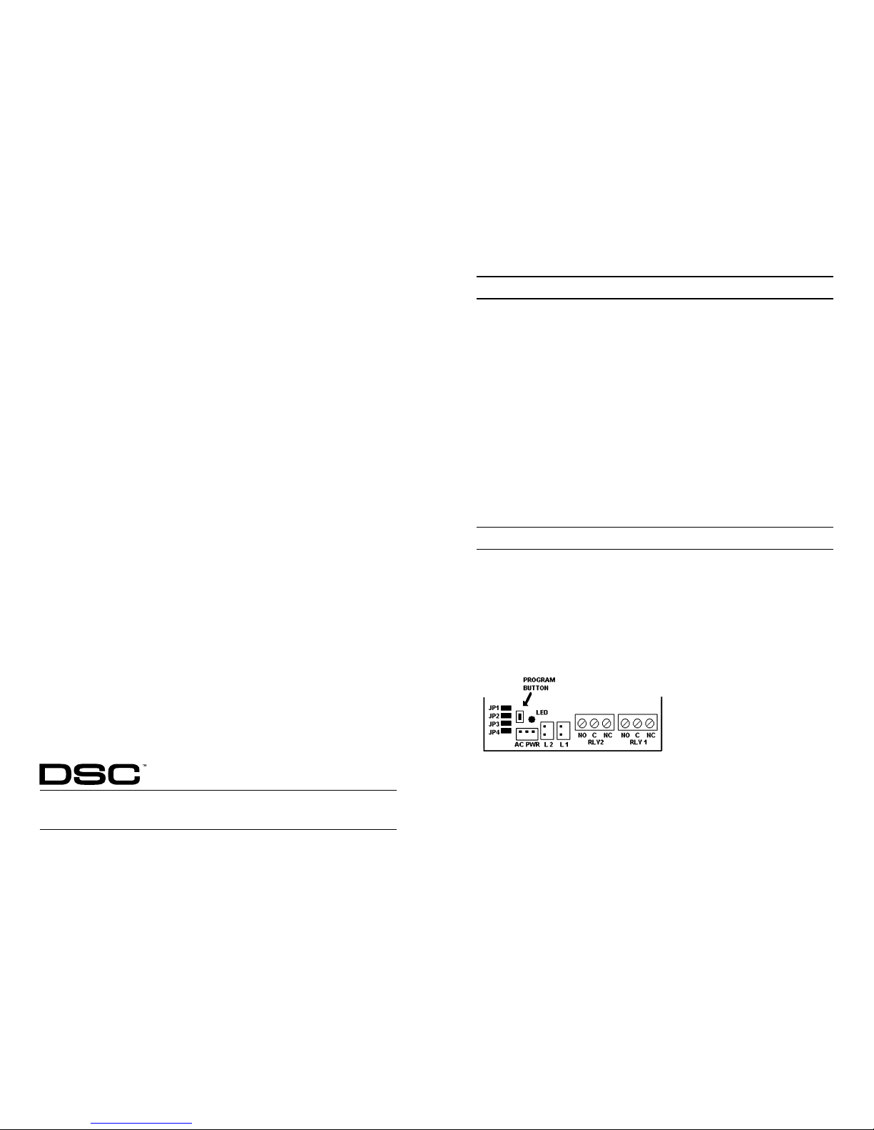
2.2 Terminal Description
The RXL2-433 has 2 on-board relays which can be used in many different applications. They
can be used to activate garage doors, security gates, Trigger X-10 devices etc.
2.3 Connecting to a Garage Door
The RXL2-433 can be mounted using the supplied screws. Make sure to mount the receiver
with the antenna wire hanging freely towards the ground. Connect relay #1, NO and C
terminals, to garage door push button #1 (The push button is typically labeled #1 and #2 at the
motors terminal strip for most manufacturers). If you are connecting the RXL2-433 to a second
garage door, connect a pair of wires from garage door #2’s push button OR motor to Relay #2.
Please consult the garage door opener instructions for proper connection. Plug in the supplied
AC/DC transformer. The RXL2-433 is defaulted to a ‘Momentary’ relay output, if you have
changed the output to a different type you must reset the relay to ‘Momentary’ for the garage
door to operate correctly. See Section “How to Program Relay #1 Output.”
FIGURE 1
2.4 Connecting to a Security Gate
Mount the RXL2-433 inside the gate enclosure as high as possible to ensure that water will not
collect inside the receiver. Connect relay #1, NO and C terminals, to the Open/Close
terminals on the gate motors terminal strip. Please consult the gate opener instructions for
proper connection. The RXL2-433 is defaulted to a ‘Momentary’ relay output, if you have
changed the output to a different type you must reset the relay to ‘Momentary’ for the gate to
operate correctly. See Section “How to Program Relay #1 Out-put.”
2.5 Connecting to an X-10 Powerflash Module
When connecting an X-10 Powerflash module to the RXL2-433, different lights within or outside
the home can be controlled, such as table lamps, or porch and driveway lights that illuminate
the entry/exit path. This can be achieved by setting the RXL2-433 a number of various ways
depending on desired operation.
• The wireless key can toggle a latched output, triggering the X-10 Powerflash module,
providing direct control of lighting. This feature can be controlled by programming the
RXL2-433 Relay # 1 or #2 to a ‘Latch’ type. See “How to Program Relay #1 Output.”
• The wireless key can turn on an output for 60 seconds lighting an entry pathway as a
customer approached the home. This feature can be controlled by programming the
RXL2-433 Relay #1 or #2 to ‘Timed’ type. See “How to Program Relay #1 Output.”
Section 3: Wireless Keys
This section describes how to enroll wireless keys. For more information on these keys, read
the instruction sheet included with each key.
3.1 Enroll and Program Wireless Keys
For wireless keys to operate on a system, you need to enroll them You can enroll 10 buttons
per relay for a maximum of 20 buttons using up to 20 different remotes to control either of the
2 on-board relays.
Enroll Wireless Keys to Relay #1
1. Remove the small door and upper case on the RXL2-433.
2. Ensure the unit is plugged into a 120VAC outlet to power the RXL2-433 using the supplied
transformer. You can plug in the adapter to any outlet for programming and then
move it to its permanent location once complete. The RXL2-433 has EEPROM built in
and will store any programmed information even if the unit is unplugged or moved in
the future.
3. Locate the program button directly behind the power plug. Press and release ONE time
to learn buttons into Relay #1. After 2 seconds the LED will Flash ON and OFF slowly
confirming it is ready to learn remote buttons.
4. Press the button of any DSC remote described in section 1.2 that you would like to control
Relay #1. Once a button is learned, the LED will flash quickly to confirm it had
received and learned that button.
NOTE: The RXL2-433 will time out if it does not see any button presses within 10 seconds. If
the unit times out complete steps 3-4 to add a button or key.
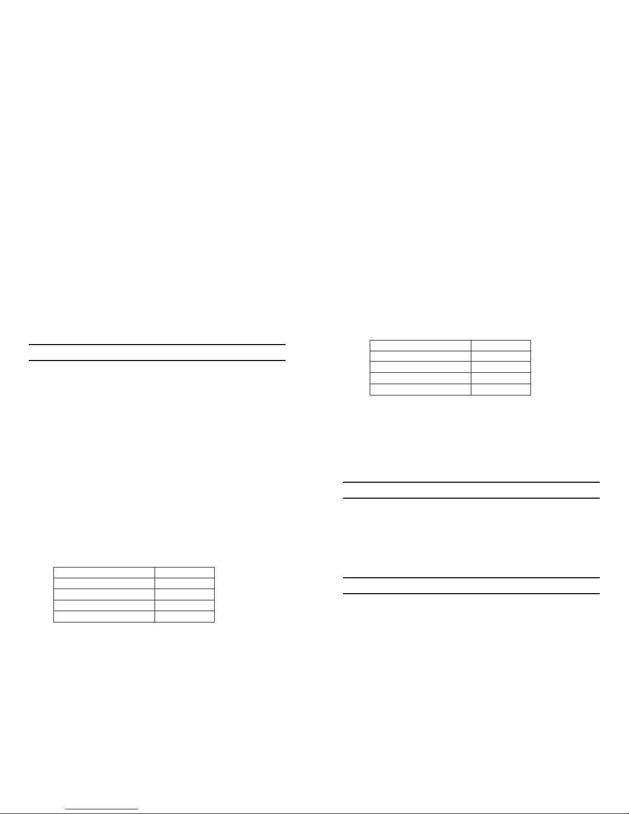
How to Program Relay #1 Output
Relay Output: Jumpers:
Momentary JP3 IN, JP4 IN
Latched JP3 OUT, JP4 IN
Timed (60 seconds) JP3 IN, JP4 OUT
Validity (only good with 12 channel) JP3 OUT, JP4 OUT
*Validity output can only be used with WS4959 and will energize the relay for as long as the
button on the remote is held. This is useful for operation when an unspecified energize time
is necessary.
Enroll Wireless Keys to Relay #2
1. Remove the small door and upper case on the RXL2-433.
2. Make sure the unit is plugged into a 120VAC outlet to power the RXL2-433 using the
supplied transformer. You can plug in the adapter to any plug for programming and then
move it to its permanent location once complete. The RXL2-433 has EEPROM built in and
will store any programmed information even if the unit is unplugged or moved in the future.
3. Locate the program button directly behind the power plug. Press and release TWICE to
learn buttons into Relay #2. The LED will flash a double flash.
4. Press the button of any DSC remote described in section 1.2 that you would like to control
Relay #2. Once a button is learned, the LED will flash quickly to confirm it had received and
learned that button.
NOTE: The RXL2-433 will time out if no buttons are pressed within 10 seconds. If the unit times
out, complete steps 3-4 to add a button or key.
How to Program Relay #2 Output
Relay Output: Jumpers:
Momentary JP1 IN, JP2 IN
Latched JP1 OUT, JP2 IN
Timed (60 seconds) JP1 IN, JP2 OUT
Validity (only good with 12 channel) JP1 OUT, JP1 OUT
*Validity output can only be used with WS4959 and will energize the relay for as long as the
button on the remote is held. This is useful for operation when an unspecified energize time
is necessary.
3.2 Deleting Wireless Keys
By entering the DELETE mode within the RXL2-433 all remotes will be removed and
subsequently must be re-enrolled before they will operate again. To enter DELETE mode, press
and HOLD the program button on the receiver. After 10 seconds the LED will turn On/Off 5
times to indicate all remotes in the system have been deleted. Follow steps 3-4 in Section 3.1 to
re-enroll desired remotes.
Section 4: Installation
4.1 Testing the Receiver
If range is poor, verify the antenna is not obstructed and that it is hanging freely towards the
ground. If range is still unacceptable, move the receiver to a different location at least 24 inches
away from its current location.
4.2 Mounting the Transformer
If connecting the transformer to an electrical outlet mounted on the ceiling of a garage, please
use the supplied velcro to secure the body of the transformer to the ceiling. For good adhesion
please ensure the surface of the ceiling and transformer are clean prior to attaching the velcro..
Section 5: Troubleshooting
1. I press the remote button and I do not hear a ‘click’ at the receiver.
Make sure the remote button that you want to operate with the RXL2-433 is enrolled properly.
See section 3.1
 Loading...