

Page 1
English
WARNIN G: Please refer to the System Installation Manual for information on limitations regarding product use and function and information on the limitations as to liability of the manufacturer.
NOTE: These instructions shall be used in conjunction with the system Installation Manual of the Control Panel with which this equipment is intended to be used.
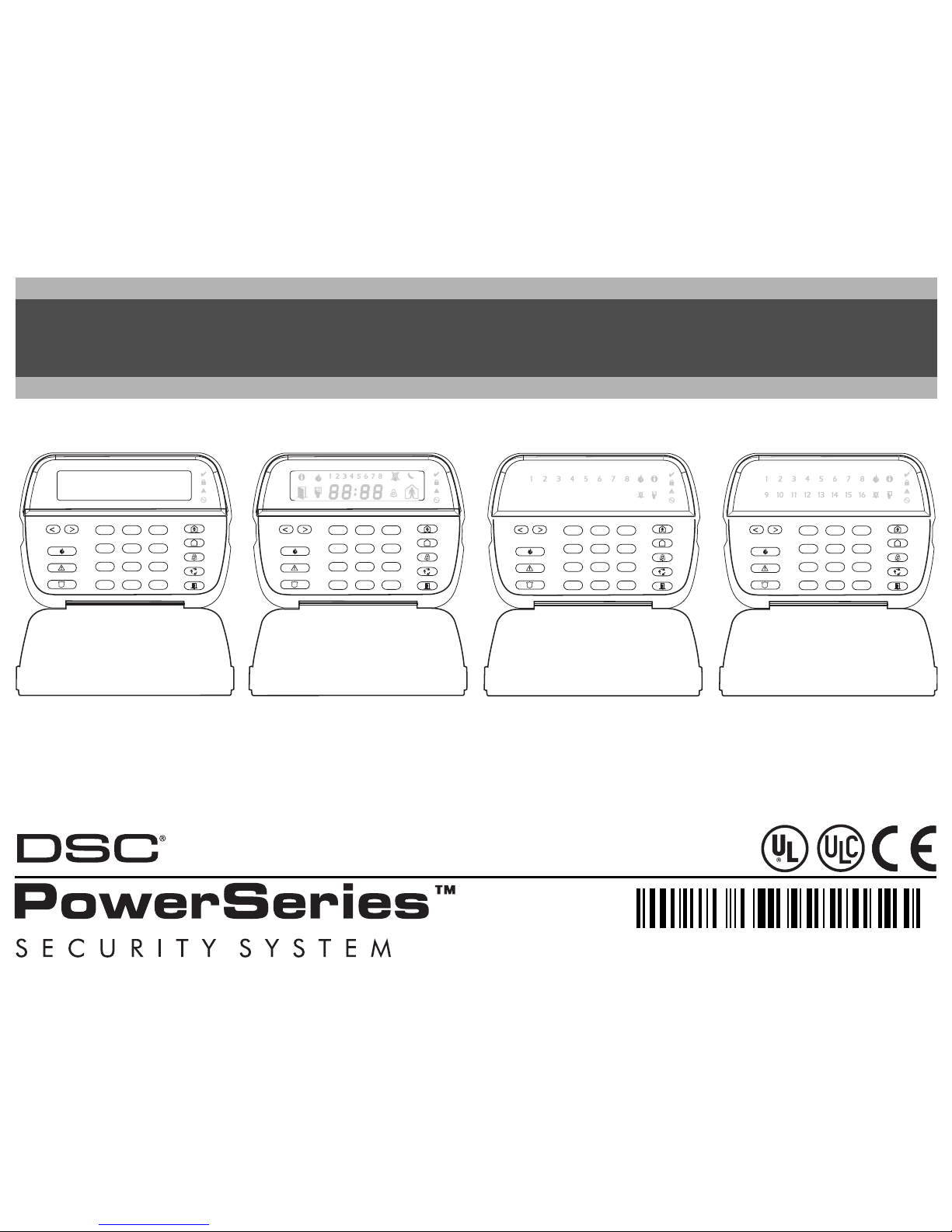
PK55XX/RFK55XX-433
Installation Instructions
123
456
78
0
*
#
9
RFK5500
PK5500
123
456
78
0
*
#
9
RFK5501
PK5501
123
456
78
0
*
#
9
RFK5508
PK5508
123
456
78
0
*
#
9
RFK5516
PK5516
2900XXXXR00X
Page 2
The PK55XX\RFK55XX keypads can be used on security systems with
up to 64 zones. These keypads are compatible with the following DSC
security systems:
The RFK55XX keypads combine a wireless receiver with the respective
PK55XX keypad.
Specifications
• Temperature range: -10°C to +55°C (14°F to 131°F), Temperature range for UL/ULC: 0°C to +49°C (32°F to 120°F)
• Humidity (MAX): 93%R.H.
• Plastic enclosure protection degree: IP30, IK04
• Voltage rating: 12V
DC nominal
• Connects to control panel via 4-wire Keybus
• 1 keypad zone input/PGM output*
• PK55XX Current draw: 50mA (standby)/125mA (maximum)
• RFK55XX Current draw: 75mA (standby)/135mA (maximum)
• Wall mount tamper
• 5 programmable function keys
• Ready (Green LED), Armed (Red LED), Trouble (Yellow LED), AC
(Green LED)
• Low temperature sensor
• Frequency: 433.92MHz
(RFK55XX-433 Only)
• Up to 32 wireless zones (RFK55XX Only)
NOTE: * Zone not to be programmed as Fire type or 24h type.
Unpacking
The Power keypad package includes the following parts:
Mounting
You should mount the keypad where it is accessible to designated
points of entry and exit. Once you have selected a dry and secure location, perform the following steps to mount the keypad.
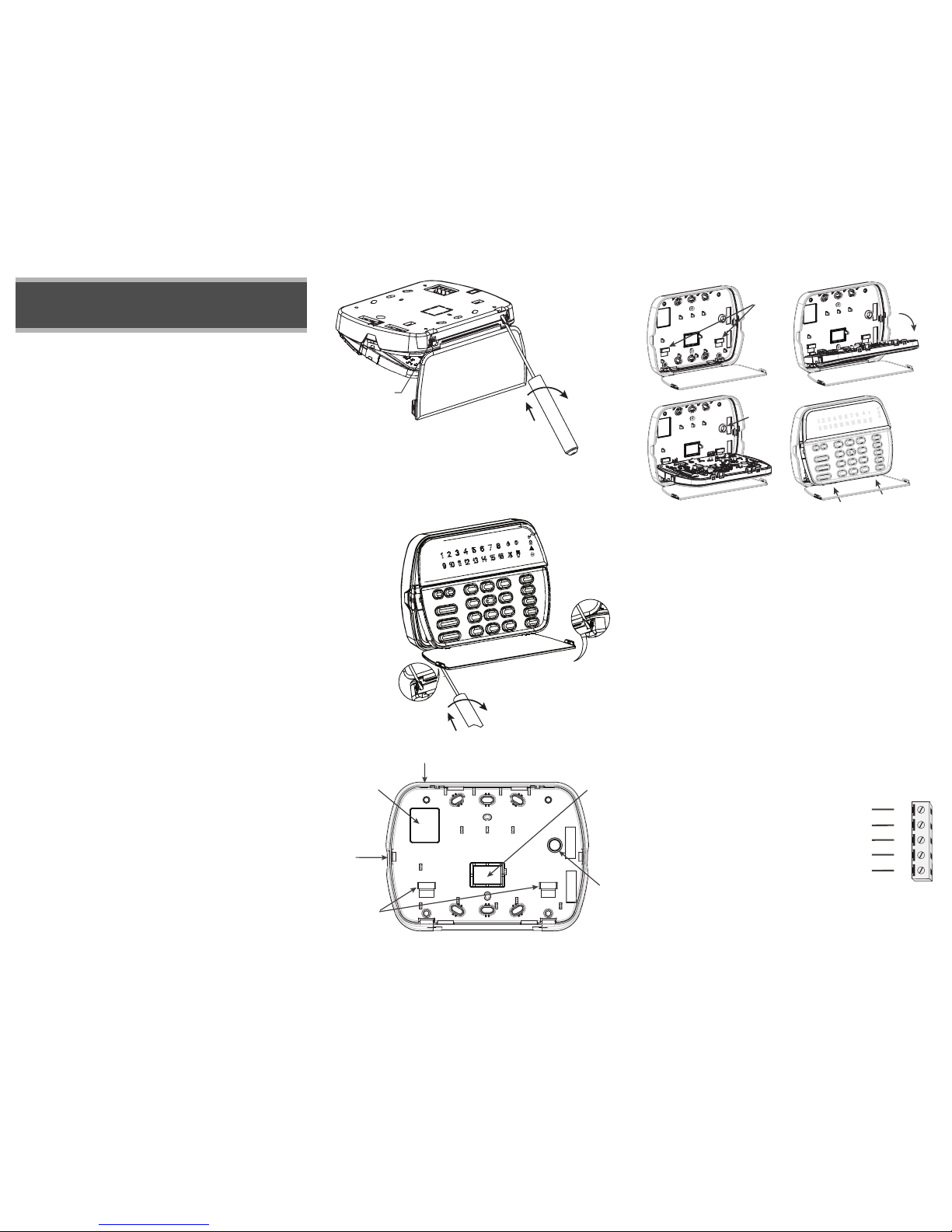
Disassemble Keypad
1. Removing the keypad from the backplate for the first time.
(a) Position the keypad as indicated, insert screwdriver and rotate.
2. Removing the keypad from backplate once mounted.
(a) Open door, holding it 90° to the keypad, as shown below.
(b) Insert screwdriver into slot located under the door hinge and
rotate the screwdriver.
Mount and Wire Keypad
1. Secure Keypad to wall using mounting holes. Use all 4 screws provided unless mounting on a single gang box.
2. Place keypad into hooks on the backplate and swing down to
engage.
3. Run wire through wiring slot or knockouts. Connect Keybus and
PGM/Zone wiring to keypad. Place tamper switch into tamper hole
on backplate.
4. Remove keypad from hooks. Place keypad into backplate, ensure
the wire is pushed back into the wall as much as possible. Route the
wire inside the keypad ensuring high components are avoided. Snap
the front assembly closed, ensuring that there is no pressure to the
keypad from the wire below.
NOTE: If any tension found between the front keypad assembly and wiring,
please open the keypad reroute the wire and close again. Repeat these
steps until the keypad is closed properly.
Wiring
1. Before wiring the unit, ensure that all power (AC transformer and
battery) is disconnected from the control panel.
2. Connect the four Keybus wires from the
control panel (red, black, yellow and
green) to the keypad terminals. Refer to
diagram:
3. If programmed as an input, you can
connect a device - such as a door contact
- to the ‘P/Z’ terminal of the keypad.
This eliminates the need to run wires back to the control panel for
the device. To connect the zone, run one wire from the device to the
‘P/Z’ terminal and the other wire from the device to the B (black)
terminal. For powered devices, run the red wire to the R (positive)
English
Installation Instructions
•PC580 •PC585 •PC1555MX •PC1565
•PC1616 •PC1832 •PC1864 •PC5005
•PC5008 •PC5010 •PC5015 •PC5016
•PC5020
•One Power keypad •Keypad inner door labels
•Four mounting screws •1 tamper switch
•2 end-of-line resistors •Installation Instructions
Disasembling
(Free-standing)
1. Insert the screwdriver into
slot at an angle and push
3. Repeat steps
1. and 2. for
left side
2. Rotate 90°
3. Repeat steps 1.
and 2. for right side
Disasembling
(Wall-Mounted)
1. Insert the screwdriver into
slot at an angle and push
2. Rotate 90°
Knock Out
Knock Out
Knock Out
Wiring Slot
Tamper
Hooks
Swing
to engage
Press to snap
1.
2.
3.
4.
Ta mp e r
Hooks
PK55XX\RFK55XX
RED
BLK
YEL
GRN
To zone or
PGM out
p
ut
R
B
Y
G
P/Z
Page 3
terminal and the black wire to the B (negative) terminal. When
using end of line supervision, connect the zone according to one of
the configurations outlined in your system’s Installation Manual.
4. If the ‘P/Z’ terminal is programmed as an output, the output follows
the PGM programmed in Section [080]. A small relay, buzzer or
other DC operated device may be connected between the positive
supply voltage and the ‘P/Z’ terminal (maximum load is 50mA).
Applying Power
Once all wiring is complete, and the equipment is secured to the building structure with at least two screws apply power to the control panel:
1. Connect the battery leads to the battery.
2. Connect the AC transformer.
For more information on control panel power specifications, see the
control panel Installation Manual.
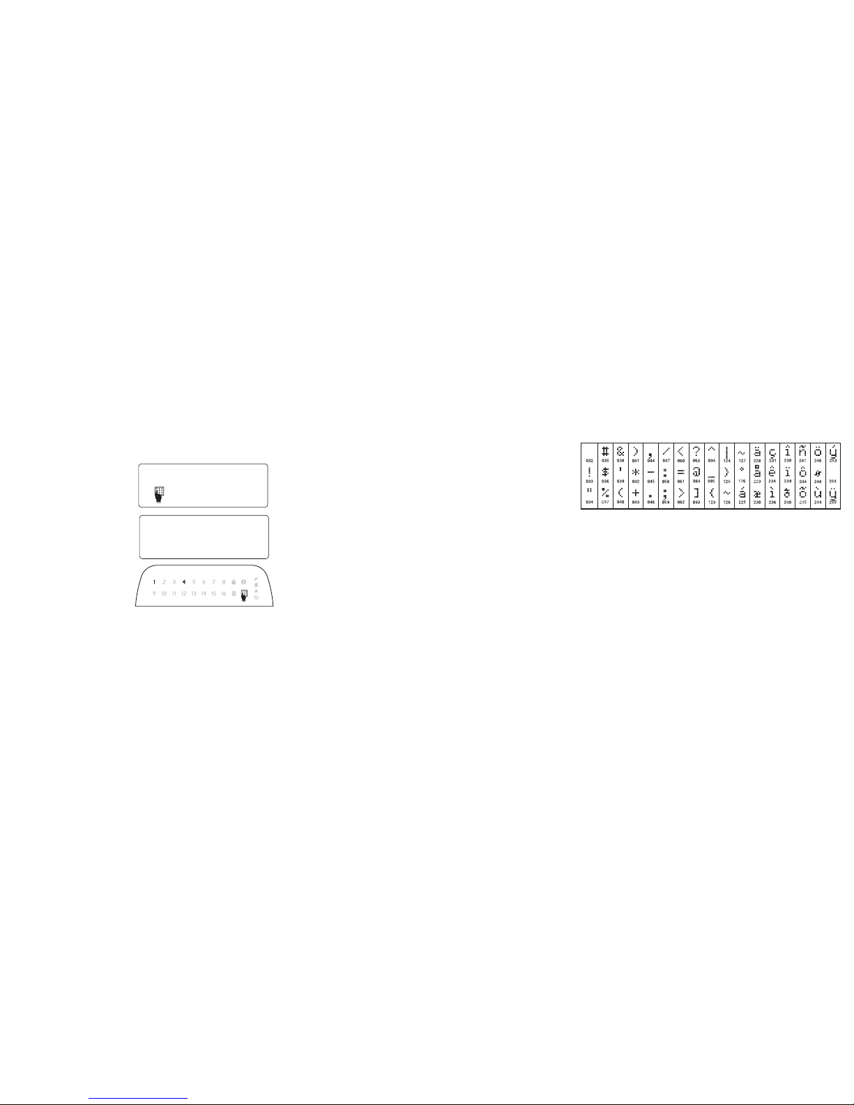
Programming the Keypad
There are several programming options available for the
keypad. These are described
below. Programming the keypad is similar to programming
the rest of the system. When
you are in the keypad programming sections, the keypad will display which options
are turned on along the top of
the display. To turn an option
on or off, press the number corresponding to the option on the number
pad. The numbers of the options that are currently turned ON will be
displayed. For example, if options 1 and 4 are on, the display will
look like this on the different keypad displays:
For information on programming the rest of your security system,
please refer to your system’s Installation Manual.
Broadcasting LCD Labels
All LCD programming is done per keypad. If more than one LCD keypad is present on the system, labels programmed at one keypad can
be broadcast to all other LCD keypads. Perform the following procedure
in order to broadcast labels:
Step 1 - Program one LCD keypad completely.
Step 2 - Make sure all LCD keypads are connected to the Keybus.
Step 3 - Enter keypad programming by pressing [,][8][Installer
Code][,], then enter section [998] at the keypad that was programmed. The keypad will now broadcast all the information programmed to all the other LCD keypads on the system.
Step 4 - When the keypad is finished press the [#] key to exit.
NOTE: Label broadcast from this keypad is only compatible with other
PK5500 and RFK5500 Keypads.
Language Programming
(PK5500\RFK5500 Only)
Hold (<>) keys for 2 seconds to enter language programming,
scroll to the desired language and Press [
,] to select.
NOTE: If section [077] option 4 is OFF, language programming
can only be performed while in installers programming.
Enrolling the Keypad
The keypad will need to be assigned to a partition and slot if supervision or keypad zones are being used. Keypad assignments and keypad option programming must be done at each keypad individually.
The 1st digit of keypad assignment is used to determine partition
assignment (1 to 8). If partitioning is not used, enter [1]. For Global
Keypads, enter [0].
NOTE: LED and ICON keypads cannot be programmed as Global Keypads
The 2nd digit of keypad assignment is used to determine slot assignment for keypad supervision. Each keypad will be assigned a different
slot number from 1 to 8. PK5500 and RFK5500 LCD keypads come
defaulted in slot 8. If LCD keypads are used one LCD keypad must
remain in slot 8.
NOTE: The RFK55XX enrolls as two modules:
Light 1 = keypad section of the RFK55XX
Light 17 = receiver section of the RFK55XX
NOTE: Deleting all wireless devices from the RFK55XX or defaulting the
RFK55XX will cause a supervisory fault.
Enter the following at each keypad installed on the system:
1. Enter Installer Programming by pressing [,][8][Installer’s Code]
2. Press [000] for Keypad Programming
3. Press [0] for Partition and Slot Assignment
4. Enter the 1st digit (0 to 8 for partition assignment)
5. Enter the 2nd digit (1 to 8 for slot assignment supervision)
6. Press the [#] key twice to exit programming.
7. After assigning all keypads, perform a supervisory reset by entering
[,][8][Installer’s Code][902] and wait for 60 seconds.
8. Press the [#] key to exit programming after 60 seconds.
Programming Labels
(PK5500\RFK5500 Only)
1. Enter keypad programming by pressing [,][8][Installer Code][,].
Enter the 3-digit section number for the label to be programmed.
2. Use the arrow keys (<>) to move the underline bar underneath
the letter to be changed.
3. Press the number keys [1] to [9] corresponding to the letter you
require. The first time you press the number the first letter will
appear. Pressing the number key again will display the next letter.
4. When the required letter or number is displayed use the arrow keys
(<>) to scroll to the next letter.
5. When you are finished programming the Zone Label, press the [
,]
key, scroll to “Save,” then press [
,].
6. Continue from Step 2 until all Labels are programmed.
NOTE: Label Programming can also be accessed from the [,][6] User
Functions Menu
ASCII Characters
Changing Brightness/Contrast
LCD Keypads
1. Press [,][6][Master code].
2. Use the [<][>] keys to scroll to either Brightness Control or Contrast Control.
3. Press [,] to select the setting you want to adjust.
4. a) ‘Brightness Control’: There are multiple backlighting levels. Use the [<][>]
keys to scroll to the desired level.
5. b) ‘Contrast Control’: There are 10 different display contrast levels. Use the
[<][>] keys to scroll to the desired contrast level.
6. To exit, press [#].
LED/ICON Keypads
1. Press [,][6][Master Code].
2. Use the [>] key to move through the 4 different backlighting levels.
3. The level is automatically saved when you press [#] to exit.
Changing the Buzzer Level
LCD Keypads
1. Press [,][6][Master Code].
2. Use the [<][>] keys to scroll to Buzzer Control.
3. There are 21 different levels, use the [<][>] keys to scroll to the desired level.
4. To exit, press [#].
LED/ICON Keypads
1. Press [,][6][Master Code].
2. Use the [<] key to move through the 21 different buzzer levels.
3. The level is automatically saved when you press [#] to exit.
4 1
Toggle Option
1 _ _ 4 _ _ _ _
[1] - A, B, C, 1 [4] - J, K, L, 4 [7] - S, T, U, 7 [0] - Space
[2] - D, E, F, 2 [5] - M, N, O, 5 [8] - V, W, X, 8
[3] - G, H, I, 3 [6] - P, Q, R, 6 [9] - Y, Z, 9,0
Page 4

Limited Warranty
Digital Security Controls warrants that for a
period of 12 months from the date of purchase,
the product shall be free of defects in materials
and workmanship under normal use and that in
fulfilment of any breach of such warranty, Digital
Security Controls shall, at its option, repair or
replace the defective equipment upon return of
the equipment to its repair depot. This warranty
applies only to defects in parts and workmanship
and not to damage incurred in shipping or handling, or damage due to causes beyond the control of Digital Security Controls such as lightning,
excessive voltage, mechanical shock, water
damage, or damage arising out of abuse, alteration or improper application of the equipment.
The foregoing warranty shall apply only to the
original buyer, and is and shall be in lieu of any
and all other warranties, whether expressed or
implied and of all other obligations or liabilities on
the part of Digital Security Controls. Digital Security Controls neither assumes responsibility for,
nor authorizes any other person purporting to act
on its behalf to modify or to change this warranty,
nor to assume for it any other warranty or liability
concerning this product.
In no event shall Digital Security Controls be liable for any direct, indirect or consequential damages, loss of anticipated profits, loss of time or
any other losses incurred by the buyer in connection with the purchase, installation or operation or
failure of this product.
Warning: Digital Security Controls recommends
that the entire system be completely tested on a
regular basis. However, despite frequent testing,
and due to, but not limited to, criminal tampering or
electrical disruption, it is possible for this product to
fail to perform as expected.
Important Information:Changes or modifications
not expressly approved by Digital Security Controls
could void the user’s authority to operate this equipment.
FCC Compliance Statement
Caution: Changes or modifications not expressly
approved by Digital Security Controls could void
your authority to use this equipment.
This equipment generates and uses radio frequency energy and if not installed and used properly, in strict accordance with the manufacturer’s
instructions, may cause interference to radio and
television reception. It has been type tested and
found to comply with the limits for Class B device
in accordance with the specifications in Subpart
“B” of Part 15 of FCC Rules, which are designed to
provide reasonable protection against such interference in any residential installation. However,
there is no guarantee that interference will not
occur in a particular installation. If this equipment
does cause interference to television or radio
reception, which can be determined by turning the
equipment off and on, the user is encouraged to
try to correct the interference by one or more of the
following measures:
• Re-orient the receiving antenna
• Relocate the alarm control with respect to the
receiver
• Move the alarm control away from the receiver
• Connect the alarm control into a different outlet
so that alarm control and receiver are on different
circuits.
If necessary, the user should consult the dealer or
an experienced radio/television technician for
additional suggestions. The user may find the following booklet prepared by the FCC helpful: “How
to Identify and Resolve Radio/Television Interference Problems”. This booklet is available from the
U.S. Government Printing Office, Washington,
D.C. 20402, Stock # 004-000-00345-4.
This Class B digital apparatus complies with
Canadian ICES-003.
Cet appareil numérique de la classe B est conforme à la norme NMB-003 du Canada.
IC:160A-RFK55XX4
The term IC before the radio certification number
signifies that the Industry Canada technical specifications were met.
EN5131-1 Grade2/Class II
Operating Instructions shall be made available to
the user.
©2006 Digital Security Controls, Toronto, Canada • www.dsc.com
Page 5

Keypad Enrollment
Enter keypad programming by pressing [,][8][Installer’s Code][000].
[0] Partition / Slot Assignment
[1]-[5] Function Key Assignment
Keypad Function Keys
Please see your system installation manual for a complete list of all the function key options available for
your system.
Keypad Programming
Enter keypad programming by pressing [,][8][Installer Code][,]
[001]-[064] Zone Label 1 to 64 (PK5500\RFK5500 Only)
ex. For Zone 1 enter section [001], for Zone 2 enter section [002] etc. Default: “Zone 1” - “Zone 64”
[065] Fire Alarm Label (28 Characters) (PK5500\RFK5500 Only)
Default:“Fire Zone”
[066] Fail to Arm Event Message (PK5500\RFK5500 Only)
Default: “System Has Failed to Arm”
[067] Alarm When Armed Event Message (PK5500\RFK5500 Only)
Default: “Alarm Occurred While Armed < >”
[071] First User Display Mask
[072] Second User Display Mask
[073] Download LCD Message Duration
(PK5500\RFK5500 Only)
Default: 003 I_____I_____I_____I (Valid entries are 000-255), 000=Unlimited Message Disp.
This number represents the number of times the Downloaded message is cleared by pressing any key while
the message is up after timeout).
Digit Option Valid Range Default
1st Partition Assignment (0=Global Keypad) 0 to 8 1 I_____I
2nd Slot Assignment 1 to 8 LED,ICON=1/LCD=8 I_____I
Function Key Button Valid Range Default Function
[1] Function Key 1 Assignment 00 to 32 03 Stay Arm I_____I_____I
[2] Function Key 2 Assignment 00 to 32 04 Away Arm I_____I_____I
[3] Function Key 3 Assignment 00 to 32 06 Chime On/Off I_____I_____I
[4] Function Key 4 Assignment 00 to 32 14 Command Output 2 I_____I_____I
[5] Function Key 5 Assignment 00 to 32 16 Quick Exit I_____I_____I
[00] - Null [08] - Bypass Mode [17] - Activate Stay/Away [28] - Partition 4 Select
[01] - Partition 1 Select [09] - Trouble Display [19] - Command Output 3 [29] - Partition 5 Select
[02] - Partition 2 Select [10] - Alarm Memory [21] - Command Output 4 [30] - Partition 6 Select
[03] - Stay Arm [11] - User Programming [22] - Activate Camera [31] - Partition 7 Select
[04] - Away Arm [12] - User Functions [23] - Bypass Recall [32] - Partition 8 Select
[05] - No Entry Arm [13] - Command Output 1 [24] - Bypass Group Recall
[06] - Chime On/Off [14] - Command Output 2[26] - Time & Date Program
[07] - System Test [16] - Quick Exit [27] - Partition 3 Select
Section Zone Label
[001] to [064] 1 to 64
I_____I_____I_____I_____I_____I_____I_____I_____I_____I_____I_____I_____I_____I_____I
I_____I_____I_____I_____I_____I_____I_____I_____I_____I_____I_____I_____I_____I_____I
[065]
I_____I_____I_____I_____I_____I_____I_____I_____I_____I_____I_____I_____I_____I_____I
I_____I_____I_____I_____I_____I_____I_____I_____I_____I_____I_____I_____I_____I_____I
[066]
I_____I_____I_____I_____I_____I_____I_____I_____I_____I_____I_____I_____I_____I_____I_____I_____I
I_____I_____I_____I_____I_____I_____I_____I_____I_____I_____I_____I_____I_____I_____I_____I_____I
[067]
I_____I_____I_____I_____I_____I_____I_____I_____I_____I_____I_____I_____I_____I_____I_____I_____I
I_____I_____I_____I_____I_____I_____I_____I_____I_____I_____I_____I_____I_____I_____I_____I_____I
Default Option ON OFF
ON I____I 1 Hold [P]anic Key prompt ON Hold [P]anic Key prompt OFF
ON I____I 2 Auto-arm Control/Time prompt ON Auto-arm Control/Time prompt OFF
ON I____I 3 Quick Arm prompt ON Quick Arm prompt OFF
ON I____I 4 Interior Arm prompt ON Interior Arm prompt OFF
OFF I____I 5 Quick Exit prompt ON Quick Exit prompt OFF
OFF I____I 6 Thermostat Control prompt ON Thermostat Control prompt OFF
OFF I____I 7 ACK All Trouble Prompt ON ACK All Trouble Prompt OFF
OFF I____I 8 Music Input prompt ON Music Input prompt OFF
Default Option ON OFF
ON I____I 1 User-initiated Call-up prompt ON User-initiated Call-up prompt OFF
OFF I____I 2For Future Use
OFF I____I 3 Walk Test prompt ON Walk Test prompt OFF
ON I____I 4 Command Output#1 prompt ON Command Output#1 prompt OFF
ON I____I 5 Command Output#2 prompt ON Command Output#2 prompt OFF
OFF I____I 6 Command Output#3 prompt ON Command Output#3 prompt OFF
OFF I____I 7 Command Output#4 prompt ON Command Output#4 prompt OFF
OFF I____I 8For Future Use
Page 6

[074] Key Options
[076] First Keypad Options
[077] Second Keypad Options
[080] PGM Terminal 1
Default: 01 I_______I _______I PGM Output Number
[101]-[108] Partition Labels (PK5500\RFK5500 Only)
ex. For Partition 1 enter section [101], for Partition 2 enter section [102] etc.
NOTE: Partition 1 Label is also used as the System Label
[120]-[151] Command Output Labels (PK5500\RFK5500 Only)
Default: “Command_O/P_1” - “Command_O/P_4”
[201]-[264] Door Chime Sound Programming
You can program the keypad to make up to four different door chime sounds for individual zones.
ex. For Zone 1 enter section [201], for Zone 2 enter section [202] etc.
[995][,] Reset Keypad Options to Factory Default
[996][,] Label Default (PK5500\RFK5500 Only)
[997] View Software Version (PK5500\RFK5500 Only)
[998][,] Initiate Global Label Broadcast (PK5500\RFK5500 Only)
[999][,] Reset Keypad EEPROM to Factory Defaults
Keypad Display Symbols
Default Option ON OFF
ON I____I 1 [F]ire Key Enabled [F]ire Key Disabled
ON I____I 2 [A]uxiliary Key Enabled [A]uxiliary Key Disabled
ON I____I 3 [P]anic Key Enabled [P]anic Key Disabled
OFF I____I 4-8 For Future Use
Default Option ON OFF
ON I____I 1 Display Code when Programming Display “Xs” when Programming
ON I____I 2 Local Clock Display ON Local Clock Display OFF
OFF I____I 3 Local Clock Displays 24-hr Time Local Clock Displays AM/PM
ON I____I 4 Auto Alarm Memory Scroll Enabled Auto Alarm Memory Scroll Disabled
OFF I____I 5 Local Display of Temperature ON Local Display of Temperature OFF
ON I____I 6 Bypass Options prompt ON Bypass Options prompt OFF
OFF I____I 7For Future Use
OFF I____I 8Auto-Scroll Open Zones ON Auto-Scroll Open Zones OFF
Default Option ON OFF
ON I____I 1 Chime Enabled for Zone Openings Chime Disabled for Zone Openings
ON I____I 2 Chime Enabled for Zone Closings Chime Disabled for Zone Closings
OFF I____I 3 5th Terminal is Keypad PGM Output 5th Terminal is Keypad Zone Input
ON I____I 4 Language Selection from Any Menu Language Selection From Installer's
OFF I____I 5 Power LED Enabled Power LED Disabled
ON I____I 6 Power LED indicates AC present Power LED indicates AC absent
ON I____I 7 Alarms always Displayed When Armed Alarms not Displayed When Armed
OFF I____I 8 Low Temperature Warning Enabled Low Temperature Warning Disabled
Section Partition Label
[101] to [108] 1 to 8
I_____I_____I_____I_____I_____I_____I_____I_____I_____I_____I_____I_____I_____I_____I
I_____I_____I_____I_____I_____I_____I_____I_____I_____I_____I_____I_____I_____I_____I
For Partition 1 Command O/P 1 to 4 enter [120] to [123] For Partition 5 Command O/P 1 to 4 enter [136] to [139]
For Partition 2 Command O/P 1 to 4 enter [124] to [127] For Partition 6 Command O/P 1 to 4 enter [140] to [143]
For Partition 3 Command O/P 1 to 4 enter [128] to [131] For Partition 7 Command O/P 1 to 4 enter [144] to [147]
For Partition 4 Command O/P 1 to 4 enter [132] to [135] For Partition 8 Command O/P 1 to 4 enter [148] to [151]
Section Part
Cmd.
Output
Label
[120]-[151]1to8 1to4
I_____I_____I_____I_____I_____I_____I_____I_____I_____I_____I_____I_____I_____I_____I
I_____I_____I_____I_____I_____I_____I_____I_____I_____I_____I_____I_____I_____I_____I
Default Option ON OFF
ON I____I 1 6 Beeps Disabled
OFF I____I 2 “Bing-Bing” Sound Disabled
OFF I____I 3 “Ding-Dong” Sound Disabled
OFF I____I 4 Alarm Tone Disabled
OFF I____I 5-8 For Future Use
8
Bypass – Indicates that there are zones automatically or
manually bypassed.
9 For Future Use
10 Arm Mode – Indicates the mode the panel is armed in.
Stay – Indicates that the panel is armed in the Stay
Mode. It will turn on at the beginning of the Exit
Delay
1 Fire – Indicates that there are fire alarms in memory.
2 Memory – Indicates that there are alarms in memory.
Away – Indicates that the panel is armed in the Away
Mode. It will turn on at the beginning of the Exit
Delay
3
Ready Light (green) – If the Ready light is on, the system
is ready for arming.
4
Armed Light (red) – If the Armed light is on, the system
has been armed successfully.
11
Chime – This icon turns on when Door Chime is enabled on
the system and will turn off when Door Chime is disabled.
5 System Trouble – Indicates that a system trouble is active.
12
Open – When zones are opened, this icon will turn on, and
7 segment displays 1 and 2 will scroll through the open
zones.
6 AC – Indicates that AC is present at the main panel.
7
Program – Indicates that the system is in Installer’s Programming, or the keypad is busy.
1
2
3
4
5
6
7
8
12
9
10
1112 7
8
Page 7

Wireless Integration
(RFK55XX Only)
Compatible Wireless Devices (RFK55XX-433 Only)
The RFK55XX can receive signals from the following devices:
Downloading
The RFK55XX product has an integrated wireless receiver. When downloading to this keypad, please select the PC5132-433 v5.1 file.
DLS2002 and greater must be used in order to have the capability of
downloading to this keypad.
Testing Wireless Devices
1. Temporarily put the wireless devices in the places you want to
mount them.
2. At a system keypad, enter [,][8][Installer Code].
3. Enter programming section [904], then enter the two digit zone
number.
NOTE: If global placement test is enabled (Section [90], option 8
ON) enter [01] to test all zones.
4. Activate the device being tested until a result is displayed on the
keypad or sounded by the keypad or bell
Activate the device until you get 3 good results in a row. Wait 10 seconds between each test on the same device. You may mount wireless
devices where results were good.
Devices indicating a bad result must be moved to another location.
You may only have to move the device a few inches to correct a bad
result.
NOTE: Do not mount any device where a “bad” test result was
indicated.
Testing Portable Device Reception
To test portable devices (e.g., WS4938, WS4939) press the button(s)
at several different points in the installation, to confirm the coverage
area. If these devices do not operate from all points in the installation,
you will need to move the RFK55XX.
Replacing Wireless Device
Batteries
1. Remove the cover of the device from its backplate. This creates a
tamper condition on the zone.
2. Refer to the battery installation instructions on the Installation
Sheet of each component. Be sure to note the proper orientation of the
batteries as you install them.
3. When the fresh batteries are in place, re-attach the cover to the
backplate. The tamper is restored and the zone sends a battery trouble
restoral signal to the receiver. The battery trouble is now clear and the
device should function normally.
NOTE: When batteries in one device need to be replaced, the batteries in all devices should be replaced at the same time.
Troubleshooting
1. When I enter the 2-digit zone number when adding a wireless
device, the keypad gives me a long beep.
• You cannot enter ESNs unless the RFK55XX is properly connected to
the Keybus.
2. I have entered the ESN for the device but when I violate the device,
the zone does not show open on the keypad.
Check the following:
• Ensure the ESN has been entered correctly
• Ensure that the zone is enabled for the partition (if partition programming is used).
• Ensure that the wireless zone is not assigned to a zone used by
PC5108 modules, an on-board zone or a keypad zone.
• Ensure that the zone is programmed for something other than
“Null Operation” and that the wireless zone attribute is turned on.
3. When I try a module placement test I get no result or “Bad” results.
Check the following:
• Verify that you are testing the correct zone
• Verify that the correct ESN was entered when the device was
enrolled
• Verify that the device is in range of the RFK55XX. Try testing the
device in the same room as the receiver.
• Confirm that the RFK55XX is properly connected to the Keybus.
• Check that you are testing the zone correctly. Refer to the instructions that came with the zone.
• Check that the batteries are working and installed correctly.
• Look for large metal objects that may be preventing the signal from
reaching the RFK55XX.
• The device must be located where consistent “Good” results are
obtained. If several devices show “Bad” results, or if panic pendants
and wireless keys operate inconsistently, move the receiver.
4. The LED on the motion detector does not turn on when I walk in
front of the unit.
• The LED on the motion detector is for walk test purposes only. See
your WLS904-433/WLS904P(L)-433 Instruction Sheet for walk test
instructions.
Notes:
•WLS914-433 Pet Immune PIR •WLS912L-433 Glass Break Detector
•WS4965 Tri-Zone Contact •WLS904(P)L-433 Pet Immune PIR
•WS4938 Panic Button •WLS925L-433 Mini Door/Window Contact
•WS4916 Smoke Detector •WS49X9 Wireless Keys
Result LED/ICON Keypad LCD Keypad Bell/Buzzer
Good Light 1 ON Steady Good 1 Beep/Squawk
Bad Light 3 ON Steady Bad 3 Beeps/Squawks
Page 8

Wireless Programming (RFK55XX Only)
Enter Wireless programming by pressing [,][8][Installer’s Code][804]
[01]-[32] Wireless Device Serial Number Zone Serial Numbers Default = 000000
[41]-[56] Wireless Key Serial Number Wireless Key Serial Numbers Default = 000000
[61]-[68] Wireless Function Key Options
Keypad Function Keys
Please see your system installation manual for a complete list of all the function key options available for your system.
[69] Wireless Keys (1-16) Partition Assignments Default = 01
[81] Wireless supervisory Window
Default: [NA] 96 = 24 hours / [EU] 10 =2.5 hours I_____I_____I
The window is programmed in 15 minute increments. Valid entries are 10 to 96, equal to 2.5 to 24 hours.
[82]-[85] Zone Device Supervision Options
[90] Other Options
NOTE: For UL Listed installations, the RF Jam detect feature must be enabled.
NOTE: For DD243 installations, the RF delinquency feature should be enabled.
NOTE: Supervision must be enabled for RF Delinquency.
[93] RF Jam Detect Zone
Default: 00 I_____I_____I Valid entries = 01 - 32, 00 = No RF Jam tone selected.
Select an unused zone that will be set to the tamper state when a jamming signal is detected.
[01] Zone 1 I_____I_____I_____I_____I_____I_____I [17] Zone 17 I_____I_____I_____I_____I_____I_____I
[02] Zone 2 I_____I_____I_____I_____I_____I_____I [18] Zone 18 I_____I_____I_____I_____I_____I_____I
[03] Zone 3 I_____I_____I_____I_____I_____I_____I [19] Zone 19 I_____I_____I_____I_____I_____I_____I
[04] Zone 4 I_____I_____I_____I_____I_____I_____I [20] Zone 20 I_____I_____I_____I_____I_____I_____I
[05] Zone 5 I_____I_____I_____I_____I_____I_____I [21] Zone 21 I_____I_____I_____I_____I_____I_____I
[06] Zone 6 I_____I_____I_____I_____I_____I_____I [22] Zone 22 I_____I_____I_____I_____I_____I_____I
[07] Zone 7 I_____I_____I_____I_____I_____I_____I [23] Zone 23 I_____I_____I_____I_____I_____I_____I
[08] Zone 8 I_____I_____I_____I_____I_____I_____I [24] Zone 24 I_____I_____I_____I_____I_____I_____I
[09] Zone 9 I_____I_____I_____I_____I_____I_____I [25] Zone 25 I_____I_____I_____I_____I_____I_____I
[10] Zone 10 I_____I_____I_____I_____I_____I_____I [26] Zone 26 I_____I_____I_____I_____I_____I_____I
[11] Zone 11 I_____I_____I_____I_____I_____I_____I [27] Zone 27 I_____I_____I_____I_____I_____I_____I
[12] Zone 12 I_____I_____I_____I_____I_____I_____I [28] Zone 28 I_____I_____I_____I_____I_____I_____I
[13] Zone 13 I_____I_____I_____I_____I_____I_____I [29] Zone 29 I_____I_____I_____I_____I_____I_____I
[14] Zone 14 I_____I_____I_____I_____I_____I_____I [30] Zone 30 I_____I_____I_____I_____I_____I_____I
[15] Zone 15 I_____I_____I_____I_____I_____I_____I [31] Zone 31 I_____I_____I_____I_____I_____I_____I
[16] Zone 16 I_____I_____I_____I_____I_____I_____I [32] Zone 32 I_____I_____I_____I_____I_____I_____I
[41] Key 1 I_____I_____I_____I_____I_____I_____I [49] Key 9 I_____I_____I_____I_____I_____I_____I
[42] Key 2 I_____I_____I_____I_____I_____I_____I [50] Key 10 I_____I_____I_____I_____I_____I_____I
[43] Key 3 I_____I_____I_____I_____I_____I_____I [51] Key 11 I_____I_____I_____I_____I_____I_____I
[44] Key 4 I_____I_____I_____I_____I_____I_____I [52] Key 12 I_____I_____I_____I_____I_____I_____I
[45] Key 5 I_____I_____I_____I_____I_____I_____I [53] Key 13 I_____I_____I_____I_____I_____I_____I
[46] Key 6 I_____I_____I_____I_____I_____I_____I [54] Key 14 I_____I_____I_____I_____I_____I_____I
[47] Key 7 I_____I_____I_____I_____I_____I_____I [55] Key 15 I_____I_____I_____I_____I_____I_____I
[48] Key 8 I_____I_____I_____I_____I_____I_____I [56] Key 16 I_____I_____I_____I_____I_____I_____I
Function Key Key 1DefaultKey 2DefaultKey 3DefaultKey 4Default
[61] Partition 1 I_____I_____I 03 I_____I_____I 04 I_____I_____I 27 I_____I_____I 30
[62] Partition 2 I_____I_____I 03 I_____I_____I 04 I_____I_____I 27 I_____I_____I 30
[63] Partition 3 I_____I_____I 03 I_____I_____I 04 I_____I_____I 27 I_____I_____I 30
[64] Partition 4 I_____I_____I 03 I_____I_____I 04 I_____I_____I 27 I_____I_____I 30
[65] Partition 5 I_____I_____I 03 I_____I_____I 04 I_____I_____I 27 I_____I_____I 30
[66] Partition 6 I_____I_____I 03 I_____I_____I 04 I_____I_____I 27 I_____I_____I 30
[67] Partition 7 I_____I_____I 03 I_____I_____I 04 I_____I_____I 27 I_____I_____I 30
[68] Partition 8 I_____I_____I 03 I_____I_____I 04 I_____I_____I 27 I_____I_____I 30
[00] - Null [06] - Chime On/Off [16] - Quick Exit [27] - Disarm
[03] - Stay Arm [07] - System Test [17] - Activate Stay/Away [28] - Fire Alarm
[04] - Away Arm [13] - Command Output 1 [19] - Command Output 3 [29] - Auxiliary Alarm
[05] - No Entry Arm [14] - Command Output 2 [21]
- Command Output 4 [30] - Panic Alarm
Key 1 I_____I_____I Key 5 I _____I_____I Key 9 I_____I_____I Key 13 I_____I_____I
Key 2 I_____I_____I Key 6 I _____I_____I Key 10 I_____I_____I Key 14 I_____I_____I
Key 3 I_____I_____I Key 7 I _____I_____I Key 11 I_____I_____I Key 15 I_____I_____I
Key 4 I_____I_____I Key 8 I _____I_____I Key 12 I_____I_____I Key 16 I_____I_____I
Default ON
[82]
Zone
Supervision
ON/OFF
[83]
Zone
Supervision
ON/OFF
[84]
Zone
Supervision
ON/OFF
[85]
Zone
Supervision
ON/OFF
Option 1 1 I_____I 9 I_____I 17 I_____I 25 I_____I
Option 2 2 I_____I 10 I_____I 18 I_____I 26 I_____I
Option 3 3 I_____I 11 I_____I 19 I_____I 27 I_____I
Option 4 4 I_____I 12 I_____I 20 I_____I 28 I_____I
Option 5 5 I_____I 13 I_____I 21 I_____I 29 I_____I
Option 6 6 I_____I 14 I_____I 22 I_____I 30 I_____I
Option 7 7
I_____I 15 I_____I 23 I_____I 31 I_____I
Option 8 8 I_____I 16 I_____I 24 I_____I 32 I_____I
NA Default EU Default Option ON OFF
OFF OFF I____I 1-4 For Future Use
ON OFF I____I 5 RF Delinquency Disabled RF Delinquency Enabled
OFF OFF I____I 6For Future Use
ON OFF I____I 7 RF Jam Detect Disabled RF Jam Detect Enabled
OFF OFF I____I 8 Global Placement Test Individual Placment Test
 Loading...