

Page 1

PK5500/RFK5500/RFK5564 v1.3
Installation Instructions, Instructions d’Installation , Instrucciones de instalación
English, Français, Español
1 2 3
4 5 6
7 8
9
0
#
*
WARNING: Please refer to the System Installation Manual for information on limitations regarding product use and function and information on the limitations as to liability of the manufacturer.
NOTE: These instructions shall be used in conjunction with the system Installation Manual of the Control Panel with which this equipment is intended to be used.
ATTENTION: Ce manuel contient des informations sur les restrictions concernant le fonctionnement et l’utilisation du produit et des informations sur les restrictions en ce qui concerne la responsabilité du fabricant. La
totalité du manuel doit être lu attentivement.
NOTE: Ce manuel doit être utilisé en conjonction avec le Manuel d'installation du Panneau de contrôle.
ATENCIÓN: Consulte el Manual de instalación del sistema para obener información sobre las limitaciones del uso y funciones del producto, así como las limitaciones de la responsabilidad del fabricante.
NOTA: Estas instrucciones deberán utilizarse conjuntamente con el Manual de instalación del sistema del Panel de control con el que se vaya a utilizar este equipo.
Page 2
English
Installation Instructions
The PK55XX\RFK55XX keypads can be used on security systems with
up to 64 zones. These keypads are compatible with the latest version
of the folllowing DSC security systems:
•PC580 •PC585 •PC1555MX •PC1565
•PC1616 •PC1832 •PC1864 •PC5005
•PC5008 •PC5010 •PC5015 •PC5016
•PC5020
The RFK55XX keypads combine a wireless receiver with the respective
PK55XX keypad.
Specifications
• Temperature range: -10°C to +55°C (14°F to 131°F), Temperature
range for UL/ULC: 0°C to +49°C (32°F to 120°F)
• Humidity (MAX): 93%R.H.
• Plastic enclosure protection degree: IP30, IK04
• Voltage rating: 12VDC nominal
• Connects to control panel via 4-wire Keybus
• 1 keypad zone input/PGM output*
• PK55XX Current draw: 50mA (standby)/125mA (maximum)
• RFK55XX Current draw: 75mA (standby)/135mA (maximum)
• Wall mount tamper
• 5 programmable function keys
• Ready (Green LED), Armed (Red LED), Trouble (Yellow LED), AC
(Green LED)
• Low temperature sensor
• Frequency: 433.92MHz (RFK55XX-433)
• Up to 32 wireless zones (RFK5500 Only)
• Up to 64 wireless zones (RFK5564 and Power v4.6+Only)
*Zone not to be programmed as Fire type or 24h type.
Unpacking
The Power keypad package includes the following parts:
•One Power keypad •Keypad inner door labels
•Four mounting screws •1 tamper switch
•2 end-of-line resistors •Installation Instructions
Mounting
You should mount the keypad where it is accessible to designated
points of entry and exit. Once you have selected a dry and secure location, perform the following steps to mount the keypad.
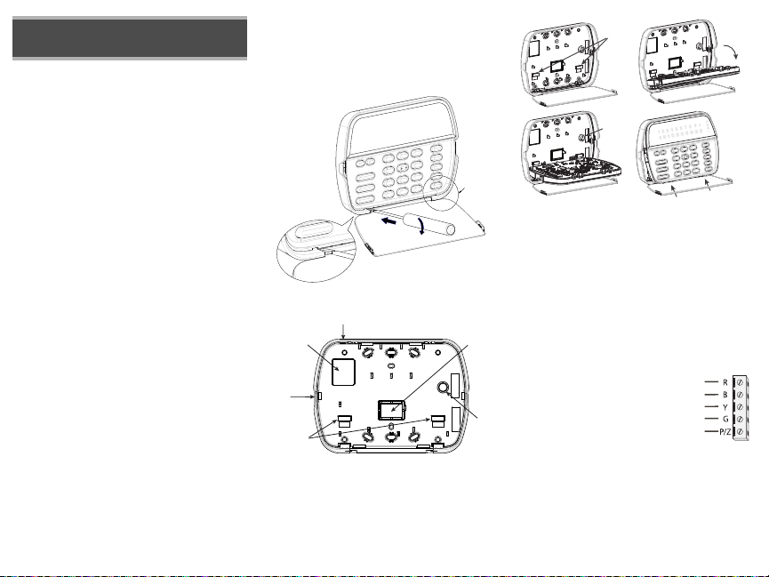
Disassemble Keypad
1. Insert a flat head screwdriver into the provided slot (first of two)
2. Move screwdriver toward the back plastic and lift as in the below diagram. This will unhook one side of the front plastic.
3. Repeat step # 1 and 2 on the second provided slot to disconnect the
front plastic and allow access for wiring.
3
1
2
Mount and Wire Keypad
Knock Out
Wiring Slot
Knock Out
Hooks
Knock Out
Tamper
1.
3.
1. Secure Keypad to wall using mounting holes. Use all 4 screws provided
unless mounting on a single gang box.
2. Place keypad into hooks on the backplate and swing down to engage.
3. Run wire through wiring slot or knockouts. Connect Keybus and PGM/Zone
wiring to keypad. Place tamper switch into tamper hole on backplate.
4. Remove keypad from hooks. Place keypad into backplate, ensure the wire
is pushed back into the wall as much as possible. Route the wire inside the
keypad ensuring high components are avoided. Snap the front assembly
closed, ensuring that there is no pressure to the keypad from the wire
below.
NOTE: If any tension found between the front keypad assembly and wiring,
please open the keypad reroute the wire and close again. Repeat these
steps until the keypad is closed properly.
Wiring
1. Before wiring the unit, ensure that all
power (AC transformer and battery) is disconnected from the control panel.
2. Connect the four Keybus wires from the control panel (red, black, yellow and green) to
the keypad terminals. Refer to diagram:
3. If programmed as an input, you can connect a device - such as a door contact - to
the ‘P/Z’ terminal of the keypad. This eliminates the need to run wires
back to the control panel for the device. To connect the zone, run one wire
from the device to the ‘P/Z’ terminal and the other wire from the device to
the B (black) terminal. For powered devices, run the red wire to the R
(positive) terminal and the black wire to the B (negative) terminal. When
using end of line supervision, connect the zone according to one of the
configurations outlined in your system’s Installation Manual.
4. If the ‘P/Z’ terminal is programmed as an output, the output follows the
PGM programmed in Section [080]. A small relay, buzzer or other DC
Hooks
Tamper
2.
4.
Press to Snap
PK55XX/RFK55XX
RED
BLK
YEL
GRN
To zone or
PGM output
Swing
to engage
Page 3

operated device may be connected between the positive supply voltage
and the ‘P/Z’ terminal (maximum load is 50mA).
NOTE: For UL Residential Fire Installations use at least one additional DSC
compatible keypad in conjunction with an RFK55XX keypad or install the
RFK55XX keypads within 3 feet from the control unit and mechanically protect the keybus wires
Applying Power
Once all wiring is complete, and the equipment is secured to the building
structure with at least two screws apply power to the control panel:
1. Connect the battery leads to the battery.
2. Connect the AC transformer.
For more information on control panel power specifications, see the control
panel Installation Manual.
Broadcasting LCD Labels
All LCD programming is done per keypad. If more than one LCD keypad is
present on the system, labels programmed at one keypad can be broadcast
to all other LCD keypads. Perform the following procedure in order to broadcast labels:
Step 1 - Program one LCD keypad completely.
Step 2 - Make sure all LCD keypads are connected to the Keybus.
Step 3 - Enter keypad programming by pressing [,][8][Installer
Code][,], then enter section [998] at the keypad that was programmed.
Press [,] to confirm the label broadcast. The keypad will now broadcast all
the information programmed to all the other LCD keypads on the system.
Step 4 - When the keypad is finished press the [#] key to exit.
NOTE: LCD Label broadcast from this keypad is only compatible
with PC1616/1832/1864 control panels and other PK5500/
RFK5500/RFK5564 keypads.
Language Programming
Hold (<>) keys for 2 seconds to enter language programming, scroll to
the desired language and Press [,] to select.
NOTE: If section [077] option 4 is OFF, language programming
can only be performed while in installers programming.
Enrolling the Keypad
The keypad will need to be assigned to a partition and slot if supervision or
keypad zones are being used. Keypad assignments and keypad option programming must be done at each keypad individually.
The 1st digit of keypad assignment is used to determine partition assignment (1 to 8). If partitioning is not used, enter [1]. For Global Keypads,
enter [0].
The 2nd digit of keypad assignment is used to determine slot assignment
for keypad supervision. Each keypad will be assigned a different slot number from 1 to 8. PK5500 and RFK5500/64 LCD keypads come defaulted in
slot 8. If LCD keypads are used one LCD keypad must remain in slot 8.
NOTE: The RFK55XX enrolls as two modules:
Keypad 8 = keypad section of the RFK55XX
PC5132 = receiver section of the RFK55XX
NOTE: Deleting all wireless devices from the RFK55XX or defaulting the
RFK55XX will cause a supervisory fault.
Enter the following at each keypad installed on the system:
1. Enter Installer Programming by pressing [,][8][Installer’s Code]
2. Press [000] for Keypad Programming
3. Press [0] for Partition and Slot Assignment
4. Enter the 1st digit (0 to 8 for partition assignment)
5. Enter the 2nd digit (1 to 8 for slot assignment supervision)
6. Press the [#] key twice to exit programming.
7. After assigning all keypads, perform a supervisory reset by entering
[,][8][Installer’s Code][902] and wait for 60 seconds.
8. Press the [#] key to exit programming after 60 seconds.
Programming Labels
1. Enter keypad programming by pressing [,][8][Installer Code][,]. Enter
the 3-digit section number for the label to be programmed.
2. Use the arrow keys (<>) to move the underline bar underneath the letter to be changed.
3. Press the number keys [1] to [9] corresponding to the letter you require.
The first time you press the number the first letter will appear. Pressing the
number key again will display the next letter
[1] - A, B, C, 1 [4] - J, K, L, 4 [7] - S, T, U, 7 [0] - Space
[2] - D, E, F, 2 [5] - M, N, O, 5 [8] - V, W, X, 8
[3] - G, H, I, 3 [6] - P, Q, R, 6 [9] - Y, Z, 9,0
4. When the required letter or number is displayed use the arrow keys
(<>) to scroll to the next letter.
5. When you are finished programming the Zone Label, press the [,] key,
scroll to “Save,” then press [,].
6. Continue from Step 2 until all Labels are programmed.
Label Library
The Label Library is a database of words commonly used when programming labels. Individual words can be combined as needed. e.g.,
Each line of the display supports a maximum of 14 characters. If a
Door.
word will not fit on a line, scroll right until the cursor appears at the first
character of the second line then add the word.
To program a custom label using the Label Library:
1. Enter keypad programming and select the label to change. e.g.,
[*][8][Installer Code][*][001] (to program the label for zone 01).
2. Press [*] to open the “Select Options” menu.
3. Press [*] again to select the “Words” option.
4. Enter the 3-digit number corresponding to a word (see Words Table
below) or use the scroll keys [<][>] to view words in the library.
5. Press [*] to select the word.
6. To add another word, repeat the above procedure from step 2.
7. To add a space, press the right scroll key [>].
.
Front +
8. To clear characters, select “Clear to End” or “Clear Display” from the
“Select Options” menu.
9. To save the current label, press [*] to access the “Select Options”
menu, scroll left [<] to “Save” then press [*] again.
Changing Brightness/Contrast
LCD Keypads
1. Press [,][6][Master code].
2. Use the [<][>] keys to scroll to either Brightness Control or Contrast Control.
3. Press [,] to select the setting you want to adjust.
4. a) ‘Brightness Control’: There are multiple backlighting levels. Use the [<][>]
keys to scroll to the desired level.
b) ‘Contrast Control’: There are 10 different display contrast levels. Use the
[<][>] keys to scroll to the desired contrast level.
5. To exit, press [#].
Changing the Buzzer Level
LCD Keypads
1. Press [,][6][Master Code].
2. Use the [<][>] keys to scroll to Buzzer Control.
3. Press [,]to select Buzzer Control.
4. There are 21 different levels. Use the [<][>] keys to scroll to the desired
level.
5. To exit, press [#].
Broadcasting Door Chime
All door chime programming is done per keypad. If more than one keypad is
present on the system, door chime programmed at one keypad can be broadcast to all other keypads. Perform the following procedure in order to broadcast
door chime:
Step 1 - Program one keypad completely.
Step 2 - Make sure all keypads are connected to the Keybus.
Step 3 - Enter keypad programming by pressing [,][8][Installer Code][,], then
enter section [994] at the keypad that was programmed. Press [,] to
confirm the chime programming broadcast. The keypad will now broadcast all the door chime information programmed to all the other keypads
on the system.
Step 4 - When the keypad is finished press the [#] key to exit.
Page 4

Keypad Enrollment
Enter keypad programming by pressing [,][8][Installer’s Code][000].
[0] Partition / Slot Assignment
Digit Option Valid Range Default
1st Partition Assignment (0=Global Keypad) 0 to 8 1 I_____I
2nd Slot Assignment 1 to 8 LED,ICON=1/LCD=8 I_____I
[1]-[5] Function Key Assignment
Function Key Button Valid Range Default Function
[1] Function Key 1 Assignment 00 to 32 03 Stay Arm I_____I_____I
[2] Function Key 2 Assignment 00 to 32 04 Away Arm I_____I_____I
[3] Function Key 3 Assignment 00 to 32 06 Chime On/Off I_____I_____I
[4] Function Key 4 Assignment 00 to 32 14 Sensor Reset I_____I_____I
[5] Function Key 5 Assignment 00 to 32 16 Quick Exit I_____I_____I
Keypad Function Keys
Refer to your system installation manual for a complete list of all function key options available for your system.
[00] - Null [08] - Bypass Mode [16] - Quick Exit [26] - Time & Date Program
[01] - Partition 1 Select [09] - Trouble Display [17] - Activate Stay/Away [27] - Partition 3 Select
[02] - Partition 2 Select [10] - Alarm Memory [18] - *Global Away Arm [28] - Partition 4 Select
[03] - Stay Arm [11] - User Programming [19] - Command Output 3 [29] - Partition 5 Select
[04] - Away Arm [12] - User Functions [21] - Command Output 4 [30] - Partition 6 Select
[05] - No Entry Arm [13] - Command Output 1 [22] - *Global Disarming [31] - Partition 7 Select
[06] - Chime On/Off [14] - Command Output 2 [23] - Bypass Recall [32] - Partition 8 Select
[07] - System Test [15] - *Global Stay Arm [24] - Bypass Group Recall [33] - Local PGM Activate
*Available only on the PC1616/PC1832/PC1864 version 4.2 or higher.
Keypad Programming
Enter keypad programming by pressing [,][8][Installer Code][,]
[001]-[064] Zone Label 1 to 64
ex. For Zone 1 enter section [001], for Zone 2 enter section [002] etc. Default: “Zone 1” - “Zone 64”
Section Zone Label
[001] to [064] 1 to 64
I_____I_____I_____I_____I_____I_____I_____I_____I_____I_____I_____I_____I_____I_____I
I_____I_____I_____I_____I_____I_____I_____I_____I_____I_____I_____I_____I_____I_____I
[065] Fire Alarm Label (28 Characters)
Default:“Fire Zone”
I_____I_____I_____I_____I_____I_____I_____I_____I_____I_____I_____I_____I_____I_____I
[065]
I_____I_____I_____I_____I_____I_____I_____I_____I_____I_____I_____I_____I_____I_____I
[066] Fail to Arm Event Message
Default: “System Has Failed to Arm”
I_____I_____I_____I_____I_____I_____I_____I_____I_____I_____I_____I_____I_____I_____I_____I_____I
[066]
I_____I_____I_____I_____I_____I_____I_____I_____I_____I_____I_____I_____I_____I_____I_____I_____I
[067] Alarm When Armed Event Message
Default: “Alarm Occurred While Armed < >”
I_____I_____I_____I_____I_____I_____I_____I_____I_____I_____I_____I_____I_____I_____I_____I_____I
[067]
I_____I_____I_____I_____I_____I_____I_____I_____I_____I_____I_____I_____I_____I_____I_____I_____I
[071] First User Display Mask
Default Option ON OFF
ON I____I 1 Hold [P]anic Key prompt ON Hold [P]anic Key prompt OFF
ON I____I 2 Auto-arm Control/Time prompt ON Auto-arm Control/Time prompt OFF
ON I____I 3 Quick Arm prompt ON Quick Arm prompt OFF
ON I____I 4 Interior Arm prompt ON Interior Arm prompt OFF
OFF I____I 5 Quick Exit prompt ON Quick Exit prompt OFF
OFF I____I 6 Thermostat Control prompt ON Thermostat Control prompt OFF
OFF I____I 7 ACK All Trouble Prompt ON ACK All Trouble Prompt OFF
OFF I____I 8 Music Input prompt ON Music Input prompt OFF
[072] Second User Display Mask
Default Option ON OFF
ON I____I 1 User-initiated Call-up prompt ON User-initiated Call-up prompt OFF
OFF I____I 2 For Future Use
OFF I____I 3 Walk Test prompt ON Walk Test prompt OFF
ON I____I 4 Command Output#1 prompt ON Command Output#1 prompt OFF
ON I____I 5 Command Output#2 prompt ON Command Output#2 prompt OFF
OFF I____I 6 Command Output#3 prompt ON Command Output#3 prompt OFF
OFF I____I 7 Command Output#4 prompt ON Command Output#4 prompt OFF
OFF I____I 8 For Future Use
[073] Download LCD Message Duration
Default: 003 I_____I_____I_____I (Valid entries are 000-255), 000=Unlimited Message Disp.This
number represents the number of times the Downloaded message is cleared by pressing any key while the
message is up after timeout).
Page 5
[074] Key Options
Default Option ON OFF
ON I____I 1 [F]ire Key Enabled [F]ire Key Disabled
ON I____I 2 [A]uxiliary Key Enabled [A]uxiliary Key Disabled
ON I____I 3 [P]anic Key Enabled [P]anic Key Disabled
OFF I____I 4-8 For Future Use
[076] First Keypad Options
Default Option ON OFF
ON I____I 1 Display Code when Programming Display “Xs” when Programming
ON I____I 2 Local Clock Display ON Local Clock Display OFF
OFF I____I 3 Local Clock Displays 24-hr Time Local Clock Displays AM/PM
ON I____I 4 Auto Alarm Memory Scroll Enabled Auto Alarm Memory Scroll Disabled
OFF I____I 5 Local Display of Temperature ON Local Display of Temperature OFF
ON I____I 6 Bypass Options prompt ON Bypass Options prompt OFF
OFF I____I 7 For Future Use
OFF I____I 8 Auto-Scroll Open Zones ON Auto-Scroll Open Zones OFF
[077] Second Keypad Options
Default Option ON OFF
ON I____I 1 Chime Enabled for Zone Openings Chime Disabled for Zone Openings
ON I____I 2 Chime Enabled for Zone Closings Chime Disabled for Zone Closings
OFF I____I 3 5th Terminal is Keypad PGM Output 5th Terminal is Keypad Zone Input
ON I____I 4 Language Selection Enabled Language Selection Disabled
OFF I____I 5 Power LED Enabled Power LED Disabled
ON I____I 6 Power LED indicates AC present Power LED indicates AC absent
ON I____I 7 Alarms always Displayed When Armed Alarms not Displayed When Armed
OFF I____I 8 Low Temperature Warning Enabled Low Temperature Warning Disabled
[080] PGM Terminal 1
I_______I _______I 1-14 Follow PGM Output Number, 15 Local PGM Pulse , 16 Local PGM T oggle
Default: 01
[082] Local PGM Output Pulse Activation Time
Default: 00 I_______I _______I Minutes (Valid Range 00-99)
Default: 05 I_______I _______I Seconds (Valid Range 00-99)
[101]-[108] Partition Labels
ex. For Partition 1 enter section [101], for Partition 2 enter section [102] etc.
Section Partition Label
[101] to [108] 1 to 8
NOTE: Partition 1 Label is also used as the System Label
I_____I_____I_____I_____I_____I_____I_____I_____I_____I_____I_____I_____I_____I_____I
I_____I_____I_____I_____I_____I_____I_____I_____I_____I_____I_____I_____I_____I_____I
[120]-[151] Command Output Labels
Default: “Command_O/P_1” - “Command_O/P_4”
For Partition 1 Command O/P 1 to 4 enter [120] to [123] For Partition 5 Command O/P 1 to 4 enter [136] to [139]
For Partition 2 Command O/P 1 to 4 enter [124] to [127] For Partition 6 Command O/P 1 to 4 enter [140] to [143]
For Partition 3 Command O/P 1 to 4 enter [128] to [131] For Partition 7 Command O/P 1 to 4 enter [144] to [147]
For Partition 4 Command O/P 1 to 4 enter [132] to [135] For Partition 8 Command O/P 1 to 4 enter [148] to [151]
Section Part
[120]-[151] 1 to 8 1 to 4
[201]-[264] Door Chime Sound Programming
You can program the keypad to make up to four different door chime sounds for individual zones.
ex. For Zone 1 enter section [201], for Zone 2 enter section [202] etc.
Default Option ON OFF
ON I____I 1 6 Beeps Disabled
OFF I____I 2 “Bing-Bing” Sound Disabled
OFF I____I 3 “Ding-Dong” Sound Disabled
OFF I____I 4 Alarm Tone Disabled
OFF I____I 5-8 For Future Use
[994][,] Initiate Global Keypad Chime Broadcast
[995][,] Reset Keypad Options to Factory Default
[996][,] Label Default
[997] View Software Version
[998][,] Initiate Global Label Broadcast
[999][,] Reset Keypad EEPROM to Factory Defaults
Cmd.
Output
Label
I_____I_____I_____I_____I_____I_____I_____I_____I_____I_____I_____I_____I_____I_____I
I_____I_____I_____I_____I_____I_____I_____I_____I_____I_____I_____I_____I_____I_____I
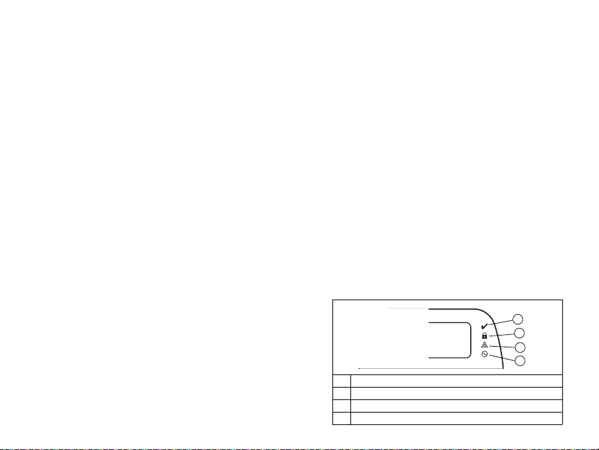
Keypad Display Symbols
1
2
3
4
1 Ready Light (green) – If the Ready light is on, the system is ready for arming.
2 Armed Light (red) – If the Armed light is on, the system has been armed successfully.
3 System Trouble – Indicates that a system trouble is active.
4 AC – Indicates that AC is present at the main panel.
Page 6

Wireless Integration (RFK55XX Only)
NOTE: Power v4.5 and lower uses 2 -digit subsections.
Compatible Wireless Devices
The RFK55XX can receive signals from the following devices:
• WLS912L-433 Glass Break Detector * • WS4945 Mini Door/Window Contact*
• WLS914-433 Pet Immune PIR* • WS4965*/WS8965 Tri-Zone Contact
• WS4904(P)*/8904(P) Pet Immune • WS4969 Wireless Keys
• WS4916*/8916 Smoke Detector • WS4975/8975 Door/Window Contact
• WS4926 Smoke Detector* • WS4985/8985 Flood Detector
• WS4938 Panic Button* • WS4913*/8913 CO Detector**
• WS4939*/8939 Wireless Key • WS4920 Wireless Repeater*
* Only these models are UL listed.
** CO Detector requires PC1616/1832/1864 v4.5 or higher.
Downloading
The RFK55XX product has an integrated wireless receiver. When downloading
to this keypad, please select the RF5132 v5.4 file. When using an RFK5564
keypad, please select the RFK5164 v5.4 file. DLS IV must be used in order to
have the capability of downloading to this keypad.
Testing Wireless Devices
1. Temporarily put the wireless devices in the places you want to mount them.
2. At a system keypad, enter [,][8][Installer Code].
3. Enter programming section [904], then enter the zone number.
NOTE: If global placement test is enabled (Section [900], option 8
ON) enter [001] to test all zones.
4. Activate the device being tested until a result is displayed on the keypad
or sounded by the keypad or bell.
Result LED/ICON Keypad LCD Keypad Bell/Buzzer
Good Light 1 ON Steady Good 1 Beep/Squawk
Bad Light 3 ON Steady Bad 3 Beeps/Squawks
While in placement test the Ready and Armed LEDs are used to indicate the
reception of a valid signal from a wireless device. The Green (Ready) LED
indicates that a transmission was received from a device that is enrolled on
the system. The Red (Armed) LED indicates that a transmission was received
from a device that is not enrolled on the system. The corresponding LED will
flash once per transmission.
Activate the device until you get 3 good results in a row. Wait 10 seconds
between each test on the same device. You may mount wireless devices
where results were good.
Devices indicating a bad result must be moved to another location. You may
only have to move the device a few inches to correct a bad result.
NOTE: Do not mount any device where a “bad” test result was indicated.
Testing Portable Device Reception
To test portable devices (e.g., WS49X9) press the button(s) at several different
points in the installation, to confirm the coverage area. If these devices do not
operate from all points in the installation, you will need to move the RFK55XX.
Receiver Placement Test
The RFK5500/RFK5564 performs best in locations where RF interference is
minimal. To find an optimal mounting location for the keypad, perform the
following placement test:
1. Temporarily connect the Keybus wires to the keypad (refer to wiring
instructions).
2. Hold the keypad in the intended mounting location.
3. Enter keypad programming mode by pressing [,][8][Installer Code],
then enter section [904].
4. If the yellow Trouble LED is on, interference levels are high and a new
mounting location should be found. If the LED is flashing or off, interference is low and the location is good.
Repeater Placement Test (in event of interference)
Power v4.6 and higher
If the “Receiver Placement Test” described above indicated the presence of
interference and you are unable to move the keypad from the interference
source, perform the following procedure while installing a WS4920 Repeater.
1. Temporarily mount the WS4920 in the desired location.
2. Use the WS4920 to test for signal noise. Refer to the WS4920 installation
manual for instructions.
3. If no noise is detected in the desired mounting location, test for adequate
signal strength through the interference at the RFK5500/RFK5564.
4. At the system keypad, enter [
5. Enter programming section [804][900] then set option 1 to “OFF”. This
option returns a “good” placement test result if the WS4920 signal
strength in the vicinity of the RFK5500/RFK5564 is within acceptable levels through the interference.
6. Exit section [804][900].
7. Enter programming section [904] and perform placement test as described
in “Testing Wireless Devices.”
8. If “bad” test results are returned, move the repeater closer to the
RFK5500/RFK5564.
9. Once “good” test results are achieved, set option 1 in section [804][900]
to “ON.”
NOTES
• All devices on the system should be enrolled on one of the WS4920
repeaters on the system.
• Perform a Repeater Placement Test only when installing the RFK5500/
5564 in areas of high interference. The preferred solution is to move the
receiver to another location. Please move the receiver as an alternate to
installing a WS4920 repeater.
Do not install both repeater and receiver in high noise areas.
•
,][8][Installer Code].
Replacing Wireless Device Batteries
1. Remove the cover of the device from its backplate. This creates a tamper
condition on the zone.
2. Refer to the battery installation instructions on the Installation Sheet of
each component. Be sure to note the proper orientation of the batteries
as you install them.
3. When the fresh batteries are in place, re-attach the cover to the backplate. The tamper is restored and the zone sends a battery trouble restoral signal to the receiver. The battery trouble is now clear and the device
should function normally.
NOTE: When batteries in one device need to be replaced, the batteries
in all devices should be replaced at the same time.
Troubleshooting
1. When I enter the zone number when adding a wireless device, the
keypad gives me a long beep.
•The keypad must be properly connected to the Keybus to enter ESNs.
2. I have entered the ESN for the device but when I violate the device,
the zone does not show open on the keypad.
Check the following:
•Ensure the ESN has been entered correctly.
•Ensure that the zone is enabled for the partition (if partition programming is used).
•Ensure that the wireless zone is not assigned to a zone used by
PC5108 modules, an on-board zone or a keypad zone.
•Ensure that the zone is programmed for something other than “Null
Operation” and that the wireless zone attribute is turned on.
3. When I try a module placement test I get no result or “Bad” results.
Check the following:
•Verify that you are testing the correct zone.
•Verify that the device is in range of the keypad. Try testing the device
in the same room as the receiver.
•Confirm that the keypad is properly connected to the Keybus.
•Check that you are testing the zone correctly. Refer to the instruc-
tions that came with the device.
•Check that the batteries are working and installed correctly.
•Look for large metal objects that may be preventing the signal from
reaching the keypad.
•The device must be located where consistent “Good” results are
obtained. If several devices show “Bad” results, or if panic pendants
and wireless keys operate inconsistently, move the receiver.
4. The LED on the motion detector does not turn on when I walk in front
of the unit.
•The LED is for walk test purposes only. See your WS4904P-433/
WS4904P(L)-433 instruction sheet for walk test instructions.
Page 7

Wireless Programming (Power v4.6 and higher)
[804] Wireless Receiver Programming (RFK55XX Only)
Enter Wireless programming by pressing [,][8][Installer’s Code][804]
[001]-[064] Wireless Device Serial Numbers
Default =000000 Zones 33-64 for RFK5564 only
[001] Zone 1 I_____I_____I_____I_____I_____I_____I [033] Zone 33 I_____I_____I_____I_____I_____I_____I
[002] Zone 2 I_____I_____I_____I_____I_____I_____I [034] Zone 34 I_____I_____I_____I_____I_____I_____I
[003] Zone 3 I_____I_____I_____I_____I_____I_____I [035] Zone 35 I_____I_____I_____I_____I_____I_____I
[004] Zone 4 I_____I_____I_____I_____I_____I_____I [036] Zone 36 I_____I_____I_____I_____I_____I_____I
[005] Zone 5 I_____I_____I_____I_____I_____I_____I [037] Zone 37 I_____I_____I_____I_____I_____I_____I
[006] Zone 6 I_____I_____I_____I_____I_____I_____I [038] Zone 38 I_____I_____I_____I_____I_____I_____I
[007] Zone 7 I_____I_____I_____I_____I_____I_____I [039] Zone 39 I_____I_____I_____I_____I_____I_____I
[008] Zone 8 I_____I_____I_____I_____I_____I_____I [040] Zone 40 I_____I_____I_____I_____I_____I_____I
[009] Zone 9 I_____I_____I_____I_____I_____I_____I [041] Zone 41 I_____I_____I_____I_____I_____I_____I
[010] Zone 10 I_____I_____I_____I_____I_____I_____I [042] Zone 42 I_____I_____I_____I_____I_____I_____I
[011] Zone 11 I_____I_____I_____I_____I_____I_____I [043] Zone 43 I_____I_____I_____I_____I_____I_____I
[012] Zone 12 I_____I_____I_____I_____I_____I_____I [044] Zone 44 I_____I_____I_____I_____I_____I_____I
[013] Zone 13 I_____I_____I_____I_____I_____I_____I [045] Zone 45 I_____I_____I_____I_____I_____I_____I
[014] Zone 14 I_____I_____I_____I_____I_____I_____I [046] Zone 46 I_____I_____I_____I_____I_____I_____I
[015] Zone 15 I_____I_____I_____I_____I_____I_____I [047] Zone 47 I_____I_____I_____I_____I_____I_____I
[016] Zone 16 I_____I_____I_____I_____I_____I_____I [048] Zone 48 I_____I_____I_____I_____I_____I_____I
[017] Zone 17 I_____I_____I_____I_____I_____I_____I [049] Zone 49 I_____I_____I_____I_____I_____I_____I
[018] Zone 18 I_____I_____I_____I_____I_____I_____I [050] Zone 50 I_____I_____I_____I_____I_____I_____I
[019] Zone 19 I_____I_____I_____I_____I_____I_____I [051] Zone 51 I_____I_____I_____I_____I_____I_____I
[020] Zone 20 I_____I_____I_____I_____I_____I_____I [052] Zone 52 I_____I_____I_____I_____I_____I_____I
[021] Zone 21 I_____I_____I_____I_____I_____I_____I [053] Zone 53 I_____I_____I_____I_____I_____I_____I
[022] Zone 22 I_____I_____I_____I_____I_____I_____I [054] Zone 54 I_____I_____I_____I_____I_____I_____I
[023] Zone 23 I_____I_____I_____I_____I_____I_____I [055] Zone 55 I_____I_____I_____I_____I_____I_____I
[024] Zone 24 I_____I_____I_____I_____I_____I_____I [056] Zone 56 I_____I_____I_____I_____I_____I_____I
[025] Zone 25 I_____I_____I_____I_____I_____I_____I [057] Zone 57 I_____I_____I_____I_____I_____I_____I
Zone 26 I_____I_____I_____I_____I_____I_____I [058] Zone 58 I_____I_____I_____I_____I_____I_____I
[026]
[027] Zone 27 I_____I_____I_____I_____I_____I_____I [059] Zone 59 I_____I_____I_____I_____I_____I_____I
[028] Zone 28 I_____I_____I_____I_____I_____I_____I [060] Zone 60 I_____I_____I_____I_____I_____I_____I
[029] Zone 29 I_____I_____I_____I_____I_____I_____I [061] Zone 61 I_____I_____I_____I_____I_____I_____I
[030] Zone 30 I_____I_____I_____I_____I_____I_____I [062] Zone 62 I_____I_____I_____I_____I_____I_____I
[031] Zone 31 I_____I_____I_____I_____I_____I_____I [063] Zone 63 I_____I_____I_____I_____I_____I_____I
[032] Zone 32 I_____I_____I_____I_____I_____I_____I [064] Zone 64 I_____I_____I_____I_____I_____I_____I
[081] Wireless Supervisory Window
Default One Way Wireless
008 for EU; 096 for NA I______I______I______I
NOTE: This entry is in minutes and when multiplied by 15 determines the length of the supervisory
window; valid entries are 004 to 096, which correlates to 1 to 24 hours.
[082]-[085] Zone Transmitter Supervision Options
Default ON
Option 1 1 I_____I 9 I_____I 17 I_____I 25 I_____I
Option 2 2 I_____I 10 I_____I 18 I_____I 26 I_____I
Option 3 3 I_____I 11 I_____I 19 I_____I 27 I_____I
Option 4 4 I_____I 12 I_____I 20 I_____I 28 I_____I
Option 5 5 I_____I 13 I_____I 21 I_____I 29 I_____I
Option 6 6 I_____I 14 I_____I 22 I_____I 30 I_____I
Option 7 7 I_____I 15 I_____I 23 I_____I 31 I_____I
Option 8 8 I_____I 16 I_____I 24 I_____I 32 I_____I
[082]
Zone
Supervision
ON/OFF
[083]
Zone
Supervision
ON/OFF
[084]
Zone
Supervision
ON/OFF
[085]
Zone
Supervision
ON/OFF
[086]-[089] Zone Transmitter Supervision Options (for RFK5564 only)
Supervision
[086]
Default ON
Zone
Option 1 33 I_____I 41 I_____I 49 I_____I 57 I_____I
Option 2 34 I_____I 42 I_____I 50 I_____I 58 I_____I
Option 3 35 I_____I 43 I_____I 51 I_____I 59 I_____I
Option 4 36 I_____I 44 I_____I 52 I_____I 60 I_____I
Option 5 37 I_____I 45 I_____I 53 I_____I 61 I_____I
Option 6 38 I_____I 46 I_____I 54 I_____I 62 I_____I
Option 7 39 I_____I 47 I_____I 55 I_____I 63 I_____I
Option 8 40 I_____I 48 I_____I 56 I_____I 64 I_____I
ON/OFF
[087]
Zone
Supervision
ON/OFF
[088]
Zone
Supervision
ON/OFF
[089]
Zone
Supervision
ON/OFF
Wireless Key Programming
[101]-[116] Wireless Key Serial Number Default = 000000
[101] Key 1 I_____I_____I_____I_____I_____I_____I [109] Key 9 I_____I_____I_____I_____I_____I_____I
[102] Key 2 I_____I_____I_____I_____I_____I_____I [110] Key 10 I_____I_____I_____I_____I_____I_____I
[103] Key 3 I_____I_____I_____I_____I_____I_____I [111] Key 11 I_____I_____I_____I_____I_____I_____I
[104] Key 4 I_____I_____I_____I_____I_____I_____I [112] Key 12 I_____I_____I_____I_____I_____I_____I
[105] Key 5 I_____I_____I_____I_____I_____I_____I [113] Key 13 I_____I_____I_____I_____I_____I_____I
[106] Key 6 I_____I_____I_____I_____I_____I_____I [114] Key 14 I_____I_____I_____I_____I_____I_____I
[107] Key 7 I_____I_____I_____I_____I_____I_____I [115] Key 15 I_____I_____I_____I_____I_____I_____I
[108] Key 8 I_____I_____I_____I_____I_____I_____I [116] Key 16 I_____I_____I_____I_____I_____I_____I
Page 8

Keypad Function Keys
Please see your system installation manual for a complete list of all the function key options available for your system.
[00] - Null [13] [03] - Stay Arm [14] [04] - Away Arm [16] -
- [,][9] No Entry Arm
[05]
- [,][4] Chime On/Off
[06]
[,][7][1]
Command Output 1 [27] - Disarm (Off)
[,][7][2]
Command Output 2 [29] - Auxiliary Alarm
[,][0]
Quick Exit [30] - Panic Alarm
[17] -
[,][1]
Activate Stay/Away [33] - Night Arm
[25] - Instant Stay Arm
[141]-[156] Wireless Function Key Programming
Function 1
[141] Key 1 I_____I_____I I_____I_____I I_____I_____I I_____I_____I
Default 03
Function 2
Default 04
Function 3
Default 27
Function 4
Default 30
[142] Key 2 I_____I_____I I_____I_____I I_____I_____I I_____I_____I
[143] Key 3 I_____I_____I I_____I_____I I_____I_____I I_____I_____I
[144] Key 4 I_____I_____I I_____I_____I I_____I_____I I_____I_____I
[145] Key 5 I_____I_____I I_____I_____I I_____I_____I I_____I_____I
[146] Key 6 I_____I_____I I_____I_____I I_____I_____I I_____I_____I
[147] Key 7 I_____I_____I I_____I_____I I_____I_____I I_____I_____I
[148] Key 8 I_____I_____I I_____I_____I I_____I_____I I_____I_____I
[149] Key 9 I_____I_____I I_____I_____I I_____I_____I I_____I_____I
Function 1
Default 03
Function 2
Default 04
Function 3
Default 27
Function 4
Default 30
[150] Key 10 I_____I_____I I_____I_____I I_____I_____I I_____I_____I
[151] Key 11 I_____I_____I I_____I_____I I_____I_____I I_____I_____I
[152] Key 12 I_____I_____I I_____I_____I I_____I_____I I_____I_____I
[153] Key 13 I_____I_____I I_____I_____I I_____I_____I I_____I_____I
[154] Key 14 I_____I_____I I_____I_____I I_____I_____I I_____I_____I
[155] Key 15 I_____I_____I I_____I_____I I_____I_____I I_____I_____I
[156] Key 16 I_____I_____I I_____I_____I I_____I_____I I_____I_____I
[181] Wireless Keys (1-16) Partition Assignment Default = 01
Valid entries are 01-08, where partition 1 is 01 and partition 8 is 08.
Key 1 I_____I_____I Key 5 I_____I_____I Key 9 I_____I_____I Key 13 I_____I_____I
Key 2 I_____I_____I Key 6 I_____I_____I Key 10 I_____I_____I Key 14 I_____I_____I
Key 3 I_____I_____I Key 7 I_____I_____I Key 11 I_____I_____I Key 15 I_____I_____I
Key 4 I_____I_____I Key 8 I_____I_____I Key 12 I_____I_____I Key 16 I_____I_____I
[900] General Wireless Options
NA
EU
Default
Default
ON ON I____I 1
OFF OFF I____I 2, 4 For Future Use
ON OFF I____I 3 Wall Tamper Disabled Wall Tamper Enabled
ON OFF I____I 5 For Future Use For Future Use
OFF OFF I____I 6 For Future Use
ON OFF I____I 7 RF Jam Detect Disabled RF Jam Detect Enabled
OFF OFF I____I 8 Global Placement Test Individual Placement Test
NOTE: For UL Listed installations, the RF Jam detect feature must be enabled.
[903] RF Jam Detect Zone
Default: 00 I_____I_____I Valid entries = 01-64, 00 = No RF Jam Zone Enabled.
Select an unused zone that will be set to the tamper state when a jamming signal is detected.
Option ON OFF
Harsh Repeater Placement Test
Disabled
Harsh Repeater Placement Test
Enabled
This Class B digital apparatus complies with Canadian ICES-003.
Cet appareil numérique de la classe B est conforme à la norme NMB-003 du Canada.
IC:160A-RFK55XX4.
The term IC before the radio certification number signifies that the Industry Canada technical specifications
were met.
Page 9

Wireless Programming (Power v4.5 and lower)
Enter Wireless programming by pressing [,][8][Installer’s Code][804].
[01]-[32] Wireless Device Serial Number
[01] Zone 1 I_____I_____I_____I_____I_____I_____I [17] Zone 17 I_____I_____I_____I_____I_____I_____I
[02] Zone 2 I_____I_____I_____I_____I_____I_____I [18] Zone 18 I_____I_____I_____I_____I_____I_____I
[03] Zone 3 I_____I_____I_____I_____I_____I_____I [19] Zone 19 I_____I_____I_____I_____I_____I_____I
[04] Zone 4 I_____I_____I_____I_____I_____I_____I [20] Zone 20 I_____I_____I_____I_____I_____I_____I
[05] Zone 5 I_____I_____I_____I_____I_____I_____I [21] Zone 21 I_____I_____I_____I_____I_____I_____I
[06] Zone 6 I_____I_____I_____I_____I_____I_____I [22] Zone 22 I_____I_____I_____I_____I_____I_____I
[07] Zone 7 I_____I_____I_____I_____I_____I_____I [23] Zone 23 I_____I_____I_____I_____I_____I_____I
[08] Zone 8 I_____I_____I_____I_____I_____I_____I [24] Zone 24 I_____I_____I_____I_____I_____I_____I
[09] Zone 9 I_____I_____I_____I_____I_____I_____I [25] Zone 25 I_____I_____I_____I_____I_____I_____I
[10] Zone 10 I_____I_____I_____I_____I_____I_____I [26] Zone 26 I_____I_____I_____I_____I_____I_____I
[11] Zone 11 I_____I_____I_____I_____I_____I_____I [27] Zone 27 I_____I_____I_____I_____I_____I_____I
[12] Zone 12 I_____I_____I_____I_____I_____I_____I [28] Zone 28 I_____I_____I_____I_____I_____I_____I
[13] Zone 13 I_____I_____I_____I_____I_____I_____I [29] Zone 29 I_____I_____I_____I_____I_____I_____I
[14] Zone 14 I_____I_____I_____I_____I_____I_____I [30] Zone 30 I_____I_____I_____I_____I_____I_____I
[15] Zone 15 I_____I_____I_____I_____I_____I_____I [31] Zone 31 I_____I_____I_____I_____I_____I_____I
[16] Zone 16 I_____I_____I_____I_____I_____I_____I [32] Zone 32 I_____I_____I_____I_____I_____I_____I
[41]-[56] Wireless Key Serial Number
[41] Key 1 I_____I_____I_____I_____I_____I_____I [49] Key 9 I_____I_____I_____I_____I_____I_____I
[42] Key 2 I_____I_____I_____I_____I_____I_____I [50] Key 10 I_____I_____I_____I_____I_____I_____I
[43] Key 3 I_____I_____I_____I_____I_____I_____I [51] Key 11 I_____I_____I_____I_____I_____I_____I
[44] Key 4 I_____I_____I_____I_____I_____I_____I [52] Key 12 I_____I_____I_____I_____I_____I_____I
[45] Key 5 I_____I_____I_____I_____I_____I_____I [53] Key 13 I_____I_____I_____I_____I_____I_____I
[46] Key 6 I_____I_____I_____I_____I_____I_____I [54] Key 14 I_____I_____I_____I_____I_____I_____I
[47] Key 7 I_____I_____I_____I_____I_____I_____I [55] Key 15 I_____I_____I_____I_____I_____I_____I
[48] Key 8 I_____I_____I_____I_____I_____I_____I [56] Key 16 I_____I_____I_____I_____I_____I_____I
Zone Serial Numbers Default = 000000
Wireless Key Serial Numbers Default = 000000
[61]-[76] Wireless Function Key Options
Function 1
Function 2
Function 3
Default 03
Default 04
I_____I_____I I_____I_____I I_____I_____I I_____I_____I
Key 1
[61]
I_____I_____I I_____I_____I I_____I_____I I_____I_____I
Key 2
[62]
I_____I_____I I_____I_____I I_____I_____I I_____I_____I
Key 3
[63]
I_____I_____I I_____I_____I I_____I_____I I_____I_____I
Key 4
[64]
I_____I_____I I_____I_____I I_____I_____I I_____I_____I
Key 5
[65]
I_____I_____I I_____I_____I I_____I_____I I_____I_____I
Key 6
[66]
I_____I_____I I_____I_____I I_____I_____I I_____I_____I
Key 7
[67]
I_____I_____I I_____I_____I I_____I_____I I_____I_____I
Key 8
[68]
Default 27
Function 4
Default 30
Function 1
Default 03
I_____I_____I I_____I_____I I_____I_____I I_____I_____I
Key 9
[69]
I_____I_____I I_____I_____I I_____I_____I I_____I_____I
Key 10
[70]
I_____I_____I I_____I_____I I_____I_____I I_____I_____I
Key 11
[71]
I_____I_____I I_____I_____I I_____I_____I I_____I_____I
Key 12
[72]
I_____I_____I I_____I_____I I_____I_____I I_____I_____I
Key 13
[73]
I_____I_____I I_____I_____I I_____I_____I I_____I_____I
Key 14
[74]
I_____I_____I I_____I_____I I_____I_____I I_____I_____I
Key 15
[75]
I_____I_____I I_____I_____I I_____I_____I I_____I_____I
Key 16
[76]
Function 2
Default 04
Function 3
Default 27
Function 4
Default 30
Keypad Function Keys
Please see your system installation manual for a complete list of all the function key options available for your system.
[00] - Null [07] - System Test [17] - Activate Stay/Away [27] - Disarm
[03] - Stay Arm [13] - Command Output 1 [18] - Global Away Arm [28] - Fire Alarm
[04] - Away Arm [14] - Command Output 2 [19] - Command Output 3 [29] - Auxiliary Alarm
[05] - No Entry Arm [15] - Global Stay Arm [21] - Command Output 4 [30] - Panic Alarm
[06] - Chime On/Off [16] - Quick Exit [22] - Global Disarm [31] - Local PGM Activate
NOTE: Wireless keys must have an access code for global arm/disarm function.
[77] Wireless Keys (1-16) Partition Assignments Default = 01
Key 1 I_____I_____I Key 5 I_____I_____I Key 9 I_____I_____I Key 13 I_____I_____I
Key 2 I_____I_____I Key 6 I_____I_____I Key 10 I_____I_____I Key 14 I_____I_____I
Key 3 I_____I_____I Key 7 I_____I_____I Key 11 I_____I_____I Key 15 I_____I_____I
Key 4 I_____I_____I Key 8 I_____I_____I Key 12 I_____I_____I Key 16 I_____I_____I
[81] Wireless supervisory Window
Default: [NA] 96 = 24 hours / [EU] 10 =2.5 hours I_____I_____I
The window is programmed in 15 minute increments. Valid entries are 10 to 96, equal to 2.5 to 24 hours.
[82]-[85] Zone Device Supervision Options
[82]
Zone
Supervision
Default ON
Option 1 1 I_____I 9 I_____I 17 I_____I 25 I_____I
Option 2 2 I_____I 10 I_____I 18 I_____I 26 I_____I
Option 3 3 I_____I 11 I_____I 19 I_____I 27 I_____I
Option 4 4 I_____I 12 I_____I 20 I_____I 28 I_____I
Option 5 5 I_____I 13 I_____I 21 I_____I 29 I_____I
Option 6 6 I_____I 14 I_____I 22 I_____I 30 I_____I
Option 7 7 I_____I 15 I_____I 23 I_____I 31 I_____I
Option 8 8 I_____I 16 I_____I 24 I_____I 32 I_____I
ON/OFF
[83]
Zone
Supervision
ON/OFF
[84]
Zone
Supervision
ON/OFF
[85]
Zone
Supervision
ON/OFF
[90] Other Options
NA Default EU Default Option ON OFF
OFF OFF I____I 1,2,4 For Future Use
ON OFF I____I 3 Wall Tamper Disabled Wall Tamper Enabled
ON OFF I____I 5 RF Delinquency Disabled RF Delinquency Enabled
OFF OFF I____I 6 For Future Use
ON OFF I____I 7 RF Jam Detect Disabled RF Jam Detect Enabled
OFF OFF I____I 8 Global Placement Test Individual Placement T est
NOTE: For UL Listed installations, the RF Jam detect feature must be enabled.
NOTE: For DD243 installations, the RF delinquency feature should be enabled.
NOTE: Supervision must be enabled for RF Delinquency.
[93] RF Jam Detect Zone
Default: 00 I_____I_____I Valid entries = 01 - 32, 00 = No RF Jam tone selected.
Select an unused zone that will be set to the tamper state when a jamming signal is detected.
Page 10

Words Table
Item # Text Item # Text Item # Text Item # Text Item # Text Item # Text Item # Text Item # Text Item # Text
001 Aborted 028 Bypass 055 Downstairs 082 Gallery 109 Light 136 Panic 163 Shed 190 Window 217 P
002 AC 029 Bypassed 056 Drawer 083 Garage 110 Lights 137 Partition 164 Shock 191 Zone 218 Q
003 Access 030 Cabinet 057 Driveway 084 Gas 111 Living 138 Patio 165 Shop 192 0 219 R
004 Active 031 Cancelled 058 Duct 085 Glass 112 Load 139 Pet 166 Side 193 1 220 S
005 Activity 032 Car 059 Duress 086 Goodbye 113 Loading 140 Phone 167 Siren 194 2 221 T
006 Alarm 033 Carbon 060 East 087 Gym 114 Low 141 Please 168 Sliding 195 3 222 U
007 All 034 Central 061 Energy Saver 088 Hallway 115 Lower 142 PM 169 Smoke 196 4 223 V
008 AM 035 Chime 062 Enter 089 Heat 116 Main 143 Police 170 Son’s 197 5 224 W
009 Area 036 Closed 063 Entry 090 Hello 117 Master 144 Pool 171 Sound 198 6 225 X
010 Arm 037 Closet 064 Error 091 Help 118 Mat 145 Porch 172 South 199 7 226 Y
011 Armed 038 Closing 065 Exercise 092 High 119 Medical 146 Power 173 Special 200 8 227 Z
012 Arming 039 Code 066 Exit 093 Home 120 Memory 147 Press 174 Stairs 201 9 228 (Space)
013 Attic 040 Communica-
014 Auxiliary 041 Computer 068 Factory 095 In 122 Monoxide 149 Progress 176 Sun 203 B 230 - (Dash)
015 Away 042 Control 069 Failure 096 Install 123 Mother’s 150 Quiet 177 Supervisory 204 C 231 _ (Underscore)
016 Baby 043 Date 070 Family 097 Interior 124 Motion 151 Rear 178 System 205 D 232 *
017 Back 044 Daughter’s 071 Father’s 098 Intrusion 125 No 152 Receiver 179 Tamper 206 E 233 #
018 Bar 045 Degrees 072 Feature 099 Invalid 126 North 153 Report 180 Temperature 207 F 234 :
019 Basement 046 Delay 073 Fence 100 Is 127 Not 154 RF 181 Test 208 G 235 /
020 Bathroom 047 Den 074 Fire 101 Key 128 Now 155 Right 182 Time 209 H 236 ?
021 Battery 048 Desk 075 First 102 Kids 129 Number 156 Room 183 To 210 I
022 Bedroom 049 Detector 076 Floor 103 Kitchen 130 Off 157 Safe 184 Touchpad 211 J
023 Bonus 050 Dining 077 Force 104 Latchkey 131 Office 158 Schedule 185 Trouble 212 K
024 Bottom 051 Disarmed 078 Foyer 105 Laundry 132 OK 159 Screen 186 Unbypass 213 L
025 Breezeway 052 Door 079 Freeze 106 Left 133 On 160 Second 187 Unit 214 M
026 Building 053 Down 080 Front 107 Level 134 Open 161 Sensor 188 Up 215 N
027 Bus 054 Download 081 Furnace 108 Library 135 Opening 162 Service 189 West 216 O
067 Exterior 094 House 121 Menu 148 Program 175 Stay 202 A 229 ’ (Apostrophe)
tor
Page 11

LIMITED WARRANTY
Digital Security Controls (DSC) warrants that for a period of 12 months from
the date of purchase, the product shall be free of defects in materials and workmanship under normal use and that in fulfilment of any breach of such warranty,
DSC shall, at its option, repair or replace the defective equipment upon return of
the equipment to its repair depot. This warranty applies only to defects in parts
and workmanship and not to damage incurred in shipping or handling, or damage due to causes beyond the control of Digital Security Controls such as lightning, excessive voltage, mechanical shock, water damage, or damage arising out
of abuse, alteration or improper application of the equipment. The foregoing
warranty shall apply only to the original buyer, and is and shall be in lieu of any
and all other warranties, whether expressed or implied and of all other obligations or liabilities on the part of Digital Security Controls. Digital Security Controls neither assumes responsibility for, nor authorizes any other person
purporting to act on its behalf to modify or to change this warranty, nor to
assume for it any other warranty or liability concerning this product. In no
event shall Digital Security Controls be liable for any direct, indirect or consequential damages, loss of anticipated profits, loss of time or any other losses
incurred by the buyer in connection with the purchase, installation or operation
or failure of this product. WARNING: Digital Security Controls recommends
that the entire system be completely tested on a regular basis. However, despite
frequent testing, and due to, but not limited to, criminal tampering or electrical
disruption, it is possible for this product to fail to perform as expected. IMPORTANT INFORMATION: Changes/modifications not expressly approved by
DSC could void the user’s authority to operate this equipment.
IMPORTANT - READ CAREFULLY: DSC Software purchased with or
without Products and Components is copyrighted and is purchased under
the following license terms:
• This End-User License Agreement (“EULA”) is a legal agreement between
You (the company, individual or entity who acquired the Software and any
related Hardware) and Digital Security Controls, a division of Tyco Safety Products Canada Ltd. (“DSC”), the manufacturer of the integrated security systems
and the developer of the software and any related products or components
(“HARDWARE”) which You acquired.
• If the DSC software product (“SOFTWARE PRODUCT” or “SOFTWARE”) is intended to be accompanied by HARDWARE, and is NOT accompanied by new HARDWARE, You may not use, copy or install the
SOFTWARE PRODUCT. The SOFTWARE PRODUCT includes computer
software, and may include associated media, printed materials, and “online” or
electronic documentation.
• Any software provided along with the Software Product that is associated
with a separate end-user license agreement is licensed to You under the terms of
that license agreement.
• By installing, copying, downloading, storing, accessing or otherwise using
the Software Product, You agree unconditionally to be bound by the terms of
this EULA, even if this EULA is deemed to be a modification of any previous
arrangement or contract. If You do not agree to the terms of this EULA, DSC is
unwilling to license the Software Product to You, and You have no right to use
it.
SOFTWARE PRODUCT LICENSE
The SOFTWARE PRODUCT is protected by copyright laws and international
copyright treaties, as well as other intellectual property laws and treaties. The
SOFTWARE PRODUCT is licensed, not sold.
1. GRANT OF LICENSE This EULA grants You the following rights:
(a) Software Installation and Use - For each license You acquire, You may
have only one copy of the SOFTWARE PRODUCT installed.
(b) Storage/Network Use - The SOFTWARE PRODUCT may not be
installed, accessed, displayed, run, shared or used concurrently on or from
different computers, including a workstation, terminal or other digital electronic
device (“Device”). In other words, if You have several workstations, You will
have to acquire a license for each workstation where the SOFTWARE will be
used.
(c) Backup Copy - You may make back-up copies of the SOFTWARE
PRODUCT, but You may only have one copy per license installed at any given
time. You may use the back-up copy solely for archival purposes. Except as
expressly provided in this EULA, You may not otherwise make copies of the
SOFTWARE PRODUCT, including the printed materials accompanying the
SOFTWARE.
2. DESCRIPTION OF OTHER RIGHTS AND LIMITATIONS
(a) Limitations on Reverse Engineering, Decompilation and Disassembly You may not reverse engineer, decompile, or disassemble the SOFTWARE
PRODUCT, except and only to the extent that such activity is expressly
permitted by applicable law notwithstanding this limitation. You may not make
any changes or modifications to the Software, without the written permission of
an officer of DSC. You may not remove any proprietary notices, marks or labels
from the Software Product. You shall institute reasonable measures to ensure
compliance with the terms and conditions of this EULA.
(b) Separation of Components - The Software Product is licensed as a single
product. Its component parts may not be separated for use on more than one
HARDWARE unit.
(c) Single INTEGRATED PRODUCT - If You acquired this SOFTWARE
with HARDWARE, then the SOFTWARE PRODUCT is licensed with the
HARDWARE as a single integrated product. In this case, the SOFTWARE
PRODUCT may only be used with the HARDWARE as set forth in this
EULA..
(d) Rental - You may not rent, lease or lend the SOFTWARE PRODUCT.
You may not make it available to others or post it on a server or web site.
(e) Software Product Transfer - You may transfer all of Your rights under this
EULA only as part of a permanent sale or transfer of the HARDWARE,
provided You retain no copies, You transfer all of the SOFTWARE PRODUCT
(including all component parts, the media and printed materials, any upgrades
and this EULA), and provided the recipient agrees to the terms of this EULA. If
the SOFTWARE PRODUCT is an upgrade, any transfer must also include all
prior versions of the SOFTWARE PRODUCT.
(f) Termination - Without prejudice to any other rights, DSC may terminate
this EULA if You fail to comply with the terms and conditions of this EULA. In
such event, You must destroy all copies of the SOFTWARE PRODUCT and all
of its component parts.
(g) Trademarks - This EULA does not grant You any rights in connection with
any trademarks or service marks of DSC or its suppliers.
3. COPYRIGHT - All title and intellectual property rights in and to the
SOFTWARE PRODUCT (including but not limited to any images,
photographs, and text incorporated into the SOFTWARE PRODUCT), the
accompanying printed materials, and any copies of the SOFTWARE
PRODUCT, are owned by DSC or its suppliers. You may not copy the printed
materials accompanying the SOFTWARE PRODUCT. All title and intellectual
property rights in and to the content which may be accessed through use of the
SOFTWARE PRODUCT are the property of the respective content owner and
may be protected by applicable copyright or other intellectual property laws and
treaties. This EULA grants You no rights to use such content. All rights not
expressly granted under this EULA are reserved by DSC and its suppliers.
4. EXPORT RESTRICTIONS - You agree that You will not export or
re-export the SOFTWARE PRODUCT to any country, person, or entity subject
to Canadian export restrictions.
5. CHOICE OF LAW - This Software License Agreement is governed by the
laws of the Province of Ontario, Canada.
6. ARBITRATION - All disputes arising in connection with this Agreement
shall be determined by final and binding arbitration in accordance with the
Arbitration Act, and the parties agree to be bound by the arbitrator’s decision.
The place of arbitration shall be Toronto, Canada, and the language of the
arbitration shall be English.
7. LIMITED WARRANTY
(a) NO WARRANTY - DSC PROVIDES THE SOFTWARE “AS IS”
WITHOUT WARRANTY. DSC DOES NOT WARRANT THAT THE
SOFTWARE WILL MEET YOUR REQUIREMENTS OR THAT
OPERATION OF THE SOFTWARE WILL BE UNINTERRUPTED OR
ERROR-FREE.
(b) CHANGES IN OPERATING ENVIRONMENT - DSC shall not be
responsible for problems caused by changes in the operating characteristics of
the HARDWARE, or for problems in the interaction of the SOFTWARE
PRODUCT with non-DSC-SOFTWARE or HARDWARE PRODUCTS.
(c) LIMITATION OF LIABILITY; WARRANTY REFLECTS
ALLOCATION OF RISK - IN ANY EVENT, IF ANY STATUTE IMPLIES
WARRANTIES OR
AGREEMENT, DSC’S ENTIRE LIABILITY UNDER ANY PROVISION OF
THIS LICENSE AGREEMENT SHALL BE LIMITED TO THE GREATER
OF THE AMOUNT ACTUALLY PAID BY YOU TO LICENSE THE
SOFTWARE PRODUCT AND FIVE CANADIAN DOLLARS (CAD$5.00).
BECAUSE SOME JURISDICTIONS DO NOT ALLOW THE EXCLUSION
OR LIMITATION OF LIABILITY FOR CONSEQUENTIAL OR
INCIDENTAL DAMAGES, THE ABOVE LIMITATION MAY NOT APPLY
TO YOU.
(d) DISCLAIMER OF WARRANTIES - THIS WARRANTY CONTAINS
THE ENTIRE WARRANTY AND SHALL BE IN LIEU OF ANY AND ALL
OTHER WARRANTIES, WHETHER EXPRESSED OR IMPLIED
(INCLUDING ALL IMPLIED WARRANTIES OF MERCHANTABILITY
OR FITNESS FOR A PARTICULAR PURPOSE) AND OF ALL OTHER
OBLIGATIONS OR LIABILITIES ON THE PART OF DSC. DSC MAKES
NO OTHER WARRANTIES. DSC NEITHER ASSUMES NOR
AUTHORIZES ANY OTHER PERSON PURPORTING TO ACT ON ITS
BEHALF TO MODIFY OR TO CHANGE THIS WARRANTY, NOR TO
ASSUME FOR IT ANY OTHER WARRANTY OR LIABILITY
CONCERNING THIS SOFTWARE PRODUCT.
(e) EXCLUSIVE REMEDY AND LIMITATION OF WARRANTY UNDER NO CIRCUMSTANCES SHALL DSC BE LIABLE FOR ANY
SPECIAL, INCIDENTAL, CONSEQUENTIAL OR INDIRECT DAMAGES
BASED UPON BREACH OF WARRANTY, BREACH OF CONTRACT,
NEGLIGENCE, STRICT LIABILITY, OR ANY OTHER LEGAL THEORY.
SUCH DAMAGES INCLUDE, BUT ARE NOT LIMITED TO, LOSS OF
PROFITS, LOSS OF THE SOFTWARE PRODUCT OR ANY
ASSOCIATED EQUIPMENT, COST OF CAPITAL, COST OF
SUBSTITUTE OR REPLACEMENT EQUIPMENT, FACILITIES OR
SERVICES, DOWN TIME, PURCHASERS TIME, THE CLAIMS OF
THIRD PARTIES, INCLUDING CUSTOMERS, AND INJURY TO
PROPERTY. WARNING: DSC recommends that the entire system be
completely tested on a regular basis. However, despite frequent testing, and due
to, but not limited to, criminal tampering or electrical disruption, it is possible for
this SOFTWARE PRODUCT to fail to perform as expected.
FCC Compliance Statement - CAUTION: Changes or modifications not
expressly approved by DSC could void your authority to use this equipment.
This equipment generates and uses radio frequency energy and if not installed
and used properly, in strict accordance with the manufacturer’s instructions, may
cause interference to radio and television reception. It has been type tested and
found to comply with the limits for Class B device in accordance with the specifications in Subpart “B” of Part 15 of FCC Rules, which are designed to provide
reasonable protection against such interference in any residential installation.
However, there is no guarantee that interference will not occur in a particular
installation. If this equipment does cause interference to television or radio
reception, which can be determined by turning the equipment off and on, the
user is encouraged to try to correct the interference by one or more of the following measures:
• Re-orient the receiving antenna
• Relocate the alarm control with respect to the receiver
• Move the alarm control away from the receiver
• Connect the alarm control into a different outlet so that alarm control and
receiver are on different circuits.
If necessary, the user should consult the dealer or an experienced radio/television
technician for additional suggestions. The user may find the following booklet
prepared by the FCC helpful: “How to Identify and Resolve Radio/Television
Interference Problems”. This booklet is available from the U.S. Government
Printing Office, Washington, D.C. 20402, Stock # 004-000-00345-4.
Operating Instructions shall be made available to the user.
CONDITIONS NOT STATED IN THIS LICENSE
© 2012 Tyco International Ltd. and its Respective Companies. All Rights Reserved. Toronto, Canada • www.dsc.com • Tech Support: 1-800-387-3630 (Canada, US), 905-760-3000 • Printed in Canada
Page 12

Instructions d’Installation
Les claviers PK55XX\RFK55XX peuvent être utilisés avec des systèmes
de sécurité ayant un maximum de 64 zones. Ces claviers sont compatibles avec la dernière version des centrales d'alarme DSC suivantes:
Français
•PC580 •PC585 •PC1555MX •PC1565
•PC1616 •PC1832 •PC1864 •PC5005
•PC5008 •PC5010 •PC5015 •PC5016
•PC5020
Les claviers RFK55XX combinent un récepteur sans fil avec le clavier
PK55XX correspondant.
Spécifications
• Plage de température: -10°C à +55°C (14°F to 131°F) Plage de
température pour UL/ULC: 0°C to +49°C (32°F to 120°F)
• Humidité (MAX): HR 93 %
• Degré de protection boîtier plastique : IP30, IK04
• Tension nominale : 12 Vc.c
• Raccordement au panneau de contrôle via le Keybus à 4 fils.
• Une entrée de zone et une sortie PGM*
• PK55XX Consommation de courant : 50mA (en veille)/125 mA (max)
• RFK55XX Consommation de courant: 75mA (en veille)/135mA (max)
• Installation murale anti-sabotage
• Cinq touches de fonctions programmables
• Voyants d’état Prêt (vert), et Armé (rouge), Trouble (Jaune), AC (vert)
• Capteur de basse température
• Fréquence: 433.92MHz (RFK55XX-433)
• 32 zones sans fil (Seulement RFK5500)
• 64 zones sans fil (Seulement RFK5564 et Power v4.6+)
* REMARQUE: Zone ne doit pas être programmée comme une
zone de type incendie (Feu) ou 24 h.
Déballage
La boîte du Power contient les éléments suivants:
•Un clavier
•Quatre vis de montage
•Deux résistance fin de lignes
•Un étiquette intérieure pour la porte du clavier
•Un commutateur anti-sabotage
•Un Manuel d’Installation
Montage
Pour le montage du clavier, choisissez un endroit près du point
d’entrée qui est sec, sécuritaire et accessible. Lorsque vous avez déterminé l’emplacement de montage, suivez les étapes suivantes.
Désassemblez le clavier
1. Insérez un tournevis plat dans la fente prévue (première fente des
deux).
2. Enfoncez le tournevis comme décrit dans le schéma ci-dessous. Cela
vous permettra de détacher une côté de la face avant.
3. Répétez étape 1 et 2 pour la deuxième fente pour enlever la face
avant du clavier afin de permettre le câblage.
3
1
2
Montage et câblage du clavier
alvéole défonçable
fente de câblage
alvéole
défonçable
crochets
alvéole
défonçable
anti-sabotage
1.
3.
1. Fixez le clavier à l’aide des trous de montage. Utilisez les 4 vis fournies à moins de faire le montage sur une seule boîte électrique.
2. Placez le clavier sur les crochets de la plaque arrière et faites basculer vers le bas pour engager.
3. Faites passez les fils dans la fente de câblage ou dans les alvéoles
défonçables. Connectez le câblage de zone Keybus et PGM au clavier. Placez l’interrupteur anti-sabotage dans le trou à cet effet sur
la plaque de montage.
4. Retirez le clavier des crochets. Placez le clavier sur la plaque de montage en vous assurant que le fil est poussé dans le mur autant que
possible. Faites passer le fil à l’intérieur du clavier en vous assurant
d’éviter les éléments sensibles. Fermez l’assemblage avant en vous
assurant que le clavier ne fait pas pression sur le fil qui est dessous.
REMARQUE : S’il y a une tension quelconque entre l’assemblage avant du
clavier et le câblage, ouvrez le clavier, déplacez le fil et refermer. Répétez
ces étapes jusqu’à ce que le clavier soit bien fermé.
Câblage
1. Avant de commencer à câbler l’unité, assurez-vous que l’alimentation (transformateur c.a. et batterie) du panneau de contrôle est
coupée.
2. Raccordez les quatre fils du Keybus qui
proviennent du panneau de contrôle
(rouge, noir, jaune et vert) sur les bornes
(R, B, Y et G) du clavier. Référez-vous au
schéma ci-dessous:
3. Si la borne ‘Z/P’ du PK55xx est programmée en tant qu’entrée, vous pouvez raccorder un dispositif sur cette borne, comme par exemple un
contact de porte. Ceci est un bon moyen d’économiser du temps et
crochets
antisabotage
2.
4.
Faites
basculer
pour engager
Appuyer pour fermer
Page 13

du câblage en évitant d’avoir à installer un câble entre le panneau de
contrôle et le contact de la porte qui se trouve à proximité du clavier.
Pour raccorder la zone, installez un câble entre le dispositif et le clavier
et raccordez un des fils provenant du dispositif sur la borne ‘Z/P’ du
clavier et un autre sur la borne B. Si le dispositif doit être alimenté,
raccordez le fil rouge à la borne R (positif) et le fil noir à la borne B
(négatif). Si une résistance de fin de ligne doit être utilisée, raccordez
la zone en vous conformant à l’une des configurations décrites dans le
manuel d’installation du système.
4. Si la borne ‘Z/P’ est programmée en tant que sortie, celle-ci suit la
programmation de la sortie PGM programmée dans la section de programmation de clavier numérique [080]. Un petit relais, un avertisseur sonore ou un autre dispositif qui fonctionne sous tension c.c. peut
être raccordé entre la borne d’alimentation positive et la borne ‘Z/P’
(consommation maximale de courant de 50mA).
REMARQUE : Pour les installations incendie homologuées UL,
utilisez au moins un clavier compatible DSC supplémentaire en
association avec le clavier RFK55XX ou installez les claviers
RFK55XX à moins de 3 pieds de l'unité de commande et protégez
mécaniquement les fils du bus de communication
Mise sous tension
Une fois que le câblage est fini et que le dispositif est fixé à la structure
de l’édifice avec au moins deux vis, mettez le panneau de contrôle sous
tension :
1. Raccordez les câbles de batterie à la batterie.
2. Branchez le transformateur CA.
Pour de plus amples informations sur les spécifications d’alimentation
du panneau de contrôle, référez-vous au manuel d’installation du panneau de contrôle.
Diffusion étiquettes LCD
Toute la programmation ACL est faite par clavier. Si plus d’un clavier
ACL est présent sur le système et si le PC5400 reçoit des intitulés, les
intitulés programmés à un clavier seront diffusés à tous les autres claviers ACL. Suivez la démarche suivante pour diffuser les intitulés:
Étape 1 - Programmez complètement un clavier ACL.
Étape 2 - Assurez-vous que tous les claviers ACL sont connectés sur le
KEYBUS.
Étape 3 - Entrez [,][8][code de l’installateur][,] pour accéder à la
programmation du clavier, puis dans la section [998] au clavier déjà
programmé. Saisir [,] pour confirmer le transfert du texte. Le clavier
diffusera tous les renseignements programmés aux autres claviers ACL
sur le système.
Étape 4 - Lorsque la diffusion est achevée, appuyez sur la touche [#]
pour sortir.
REMARQUE : La diffusion d’étiquette ce clavier est seulement compatibleavec la centrale PC1616/PC1832/PC1864 et d'autres claviers PK5500/
RFK5500/64.
Programmation de langue
Maintenir les touches (<>) pendant 2 secondes pour entrer le langage de programmation, faites défiler jusqu’au langage désiré et
appuyez sur [,] pour choisir.
REMARQUE : Si l’option 4 de la section [077] option 4 est désactivée, le langage de programmation ne peut se faire que dans la
programmation de l’installateur.
Attribution du clavier
Le clavier devra être assigné à une partition et à un emplacement si les
zones de supervision ou de clavier sont occupées. L’attribution du clavier et l’option de programmation de clavier doivent être faites individuellement à chaque clavier.
Le 1er chiffre de l’attribution du clavier est utilisé pour déterminer
l’attribution de la partition (1 à 8). S’il n’y a pas de partitionnement,
tapez [1]. Pour les claviers globaux, tapez [0].
Le 2e chiffre de l’attribution du clavier est utilisé pour déterminer l’attribution de l’emplacement pour le clavier de supervision. On assigne à
chaque clavier un numéro d’emplacement différent, de 1 à 8. Les clavier ACL PK5500 et RFK5500/64 LCD sont par défaut assignés à
l’emplacement 8. Si les claviers LCD sont utilisés un clavier LCD doit
être assigné à l’emplacement 8.
REMARQUE : Le RFK55XX est attribué en tant que deux modules :
Clavier 8 = section clavier du RFK55XX
RF5132 = section récepteur du RFK55XX
REMARQUE : L’annulation de tous les dispositifs sans fil du RFK55XX ou la
mise aux paramètres par défaut du RFK55XX provoquera une anomalie de
supervision.
Entrez ce qui suit pour chacun des claviers qui est installé dans le système:
1. Accédez au mode de programmation de l’installateur en entrant
[,][8][code de l’installateur]
2. Entrez [000] pour accéder à la programmation du clavier.
3. Appuyez sur [0] pour accéder à l’attribution de la partition et de
l’emplacement de mémoire du clavier.
4. Entrez le 1er chiffre (0 à 8 pour l’attribution d’une partition)
5. Entrez le 2e chiffre (1 à 8 pour l’attribution de l’emplacement de
supervision)
6. Pour quitter le mode de programmation, appuyez deux fois sur [#]
7. Après avoir assigné tous les claviers, effectuez une réinitialisation de
supervision en entrant [,][8][code de l’installateur][902] et attendre 60 secondes.
8. Appuyez sur [#] pour sortir de la programmation après 60 secondes.
Programmation d’étiquette
1. Entrez [,][8][code de l’installateur][,] pour accéder à la programmation du clavier. Entrez les trois chiffres de la section pour que l’intitulé soit programmé.
2. Utilisez les touches flèches (<>) pour déplacer le trait bas sous la
lettre à changer.
3. Appuyez sur la touche du chiffre [1] à [9] correspondant à la lettre
requise. La première fois que vous appuyez sur le chiffre, la première
lettre apparaît. En appuyant à nouveau sur la touche chiffre vous passerez à la lettre suivante.
[1] - A, B, C, 1 [4] - J, K, L, 4 [7] - S, T, U, 7 [0] - Espace
[2] - D, E, F, 2 [5] - M, N, O, 5 [8] - V, W, X, 8
[3] - G, H, I, 3 [6] - P, Q, R, 6 [9] - Y, Z, 9,0
4. Lorsque vous devez afficher une autre lettre ou un autre chiffre utilisez
les touches flèches (<>) pour faire défiler jusqu’à la lettre suivante.
5. Lorsque vous avez fini la programmation de l’intitulé de zone,
appuyez sur la touche [,], faites défiler jusqu’à “Sauvegarde” puis
appuyez sur [,].
6. Continuez à partir de l’étape 2 jusqu’à ce que tous les intitulés soient
programmés.
Bibliothèque de textes
La bibliothèque de textes est une base de données de mots fréquemment utilisés
lors de la programmation des textes. Les mots peuvent être combinés selon les
besoins. par ex. Porte + Devant. Chaque ligne de l'affichage permet un maximum de 14 caractères. Si un mot ne rentre pas dans une ligne, faites défiler
jusqu'à ce que le curseur apparaisse au premier caractère de la deuxième ligne
puis ajouter le mot.
Pour programmer un texte individualisé en utilisant la bibliothèque de textes :
1. Saisissez la programmation de clavier et choisir le texte à changer. Par ex.,
[,][8][Code de l'installateur][,][001] (pour paramétrer le texte pour la
zone 01).
2. Appuyez sur [,] pour ouvrir le menu « Sélection d'options ».
3. Appuyez à nouveau sur [,] pour sélectionner l'option « Mots ».
4. Saisissez le nombre à 3 chiffres correspondant à un mot (voir le tableau
Mots) ou utilisez les touches de défilement [<][>] pour faire défiler les
mots de la bibliothèque.
5. Appuyez sur [,] pour sélectionner le mot.
6. Pour ajouter un autre mot, répétez la procédure ci-dessus à partir de
l'étape 2.
7. Pour ajouter un espace, appuyez sur la touche de défilement de droite
[>].
Page 14

8. Pour effacer des caractères, sélectionnez « Effacer jusqu'à la fin » ou « Effacer affichage » sur le menu « Sélection
d'options ».
9. Pour sauvegarder le texte, appuyez sur [,] pour accéder au menu « Sélection d'options », faites défiler vers la
gauche [<] jusqu'à " Sauvegarde " puis appuyez à nouveau sur [,].
Changer la luminosité et le contraste
Claviers LCD
1. Tapez [,][6][code maître].
2. Utilisez les touches flèches [<>] pour le contrôle de la luminosité ou du contraste.
3. Tapez [,] pour sélectionner le paramètre que vous désirez ajuster.
4. a) “Contrôle de la luminosité” : Il y a 10 niveaux de rétro-éclairage. Utilisez les touches flèches pour faire
défiler jusqu'au niveau désiré.
b) “Contrôle du contraste” : Il y a 10 niveaux de contraste. Utilisez les touches flèches pour faire défiler
jusqu'au niveau de contraste désiré.
5. Pour sortir de cette programmation, appuyez sur [#].
Changement de volume du résonateur
Clavier LCD
1. Tapez [,][6][code maître].
2. Utilisez les touches flèches [<>] pour défiler jusqu'au contrôle de l'avertisseur.
3. Saisissez [,] pour sélectionner contrôle de l'avertisseur.
4. Utilisez les touches flèches [<>] pour défiler jusqu'au niveau d’avertisseur désiré parmi les 21 sélections
possibles.
5. Appuyez sur [#] pour sortir.
Transmission carillon de porte
La programmation carillon de porte est faite par clavier. Lorsqu'il y a plusieurs claviers dans le système, la
fonction carillon de porte programmé sur un clavier peut être transmis vers tous les autres claviers. Effectuez
la procédure suivante pour la transmission de la fonction carillon de porte:
Etape 1 - Programmez un clavier entièrement.
Etape 2 - Vérifiez si tous les claviers sont raccordé au keybus.
Etape 3 - Entrez dans la programmation du clavier avec [
l'adresse [994] au clavier qui a été programmé. Saisir [,] pour confirmer le transfert de programmation du carillon. Le clavier transmet maintenant la programmation carillon de porte vers
tous les autres claviers dans le système.
Etape 4 - Quand le clavier est prêt, appuyez la touche [#] pour quitter.
Attribution du clavier
Entrez [,][8][code de l’installateur][000] pour accéder à la programmation du clavier.
,][8][code installateur][,], puis entrez dans
[0] Partition/Adresse de l’emplacement
Chiffre Option
1er Attribution de partition (0=clavier global) 0 - 8 1 I_____I
2e Attribution d’emplacement 1 - 8 LED,ICON=1/LCD=8 I_____I
Portée
valable
Défaut
[1]-[5] Attribution de la touche de fonction
Attribution de la touche
de fonction
Touche
[1] Touche de fonction 1 00 - 32 03 Armement A domicile I_____I_____I
[2] Touche de fonction 2 00 - 32 04 Armement Absent I_____I_____I
[3] Touche de fonction 3 00 - 32 06 Carillon (MAR/ARR) I_____I_____I
[4] Touche de fonction 4 00 - 32 14 Reset détecteurs I_____I_____I
[5] Touche de fonction 5 00 - 32 16 Sortie Rapide I_____I_____I
Touches de fonction du clavier
Veuillez voir le manuel d’installation de votre système pour une liste complète de toutes les options touches
de fonction offertes par votre système.
[00] Touche nulle [11] Programmation utilisateur [23] Suspendre rappel
[01] Partition 1 Sélectionnez [12] Fonctions utilisateur [24] Suspendre rappel de groupe
[02] Partition 2 Sélectionnez [13] Sortie de commande1 [26] Date et l’heure
[03] Armement A domicile [14] Sortie de commande 2 [27] Partition 3 Sélectionnez
[04] Armement Absent [15] Armer Présent Global* [28] Partition 4 Sélectionnez
[05] Armement sans délai d'entrée [16] Sortie Rapide [29] Partition 5 Sélectionnez
[06] Carillon [17] Activer modes A domicile/Absent [30] Partition 6 Sélectionnez
[07] Test du système [18] Armer Absent Global* [31] Partition 7 Sélectionnez
[08] Mode suspension [19] Sortie de commande 3 [32] Partition 8 Sélectionnez
[09] Mode trouble [21] Sortie de commande 4 [33] Activation PGM local
[10] Mémoire d'alarme [22] Désarmer global*
*Uniquement valable pour la PC1616/PC1832/PC1864 version 4.2 et ultérieure
Programmation du clavier
Entrez [,][8][code de l’installateur][,] pour accéder à la programmation du clavier.
[001]-[064] Les étiquettes de zones 1 à 64
ex. Pour la Zone 1 entrez section [001], pour la Zone 2 entrez section [002] etc. Paramètre par défaut :
“Zone 01” - “Zone 64”
Section Zone Label
[001]-[064] 1 - 64
[065] Étiquettes de Alarme incendie (28 caractères)
Défaut:“ Zone Feu”
[065]
[066] Message Échec d’armement
I_____I_____I_____I_____I_____I_____I_____I_____I_____I_____I_____I_____I_____I_____I
I_____I_____I_____I_____I_____I_____I_____I_____I_____I_____I_____I_____I_____I_____I
I_____I_____I_____I_____I_____I_____I_____I_____I_____I_____I_____I_____I_____I_____I
I_____I_____I_____I_____I_____I_____I_____I_____I_____I_____I_____I_____I_____I_____I
Portée
valable
Paramèt
re par
défaut
Fonction
Page 15

Défaut: “Système a Echec d’Armement”
I_____I_____I_____I_____I_____I_____I_____I_____I_____I_____I_____I_____I_____I_____I_____I_____I
[066]
I_____I_____I_____I_____I_____I_____I_____I_____I_____I_____I_____I_____I_____I_____I_____I_____I
[067] Message événement alarme pendant l’armement
Défaut: “Aparition Alarme Quand Armè < >”
I_____I_____I_____I_____I_____I_____I_____I_____I_____I_____I_____I_____I_____I_____I_____I_____I
[067]
I_____I_____I_____I_____I_____I_____I_____I_____I_____I_____I_____I_____I_____I_____I_____I_____I
[071] Premier masque d’affichage de l’utilisateur
Paramètre par
défaut
MARCHE I____I 1
MARCHE I____I 2
MARCHE I____I 3
MARCHE I____I 4
ARRÊT I____I 5
ARRÊT I____I 6
ARRÊT I____I 7
ARRÊT I____I 8
[072] Deuxième masque d’affichage de l’utilisateur
Paramètre par
défaut
MARCHE I____I 1
ARRÊT I____I 2
ARRÊT I____I 3
MARCHE I____I 4
MARCHE I____I 5
ARRÊT I____I 6
ARRÊT I____I 7
ARRÊT I____I 8
[073] Durée du message ACL téléchargé
Paramètre par défaut: 003 I_____I_____I_____I (Les entrées valables sont 000-255, 000=Affichage
de message illimité. Ce chiffre représente le nombre de fois que le message téléchargé est effacé en appuyant
sur une touche quelconque pendant l’affichage du message après temporisation).
Option MARCHE ARRÊT
Message guide maintien des touches de
[P]anique MARCHE
Message guide contrôle armement automatique/Heure MARCHE
Message guide armement rapide MARCHE Message guide armement rapide ARRÊT
Message guide armement intérieur MARCHE Message guide armement intérieur ARRÊT
Message guide sortie rapide MARCHE Message guide sortie rapide ARRÊT
Message guide réglage de la température
MARCHE
AR tous les messages guides Trouble MARCHE AR tous les messages guides Trouble ARRÊT
Entrée de musique MARCHE Entrée de musique ARRÊT
Message guide maintien des touches de
[P]anique ARRÊT
Message guide contrôle armement automatique/Heure ARRÊT
Message guide réglage de la température
ARRÊT
Option MARCHE ARRÊT
Message guide appel initié par l’utilisateur
MARCHE
Pour utilisation future
Message guide essai de marche MARCHE Message guide Essai de marche ARRÊT
Message guide sortie de commande #1
MARCHE
Message guide sortie de commande #2
MARCHE
Message guide sortie de commande #3
MARCHE
Message guide sortie de commande #4
MARCHE
Pour utilisation future
Message guide appel initié par l’utilisateur
ARRÊT
Message guide sortie de commande #1
ARRÊT
Message guide sortie de commande #2
ARRÊT
Message guide sortie de commande #3
ARRÊT
Message guide sortie de commande #4
ARRÊT
[074] Options des touches
Paramètre par
défaut
MARCHE I____I 1 Touches [F]eu activées Touches [F]eu désactivées
MARCHE I____I 2 Touches [A]uxiliaire activées Touches [A]uxiliaire désactivées
MARCHE I____I 3 Touches [P]anique activées Touches [P]anique désactivées
ARRÊT I____I 4-8 Pour utilisation future
Option MARCHE ARRÊT
[076] Premières Options de Clavier
Paramètre par
défaut
MARCHE I____I 1
MARCHE I____I 2
ARRÊT I____I 3
MARCHE I____I 4
ARRÊT I____I 5
MARCHE I____I 6
ARRÊT I____I 7
ARRÊT I____I 8
Opt. MARCHE ARRÊT
Affichage du code d’accès lors de la programmation
Affichage horloge locale activé Affichage horloge locale désactivé
Horloge locale affiche heure format 24 heures Horloge locale affiche heure format AM/PM
Défilement automatique de l’alarme en
mémoire activé
Affichage de la température locale activé Affichage de la température locale désactivé
Message guide des options de suspension
MARCHE
Pour utilisation future
Défilement automatique zones ouvertes activé Défilement automatique zones ouvertes désactivé
Affichage ‘X’ lors de la programmation
Défilement automatique de l’alarme en mémoire
désactivé
Message guide des options de suspension ARRÊT
Page 16

[077] Deuxième Options de Clavier
Paramètre par
défaut
MARCHE
MARCHE
ARRÊT
MARCHE
ARRÊT
MARCHE
MARCHE
ARRÊT
Opt MARCHE ARRÊT
Carillon pour l'ouverture de zone permis activé Carillon pour l'ouverture de zone permis désactivé
I____I 1
Carillon pour la fermeture de zone activé Carillon pour la fermeture de zone désactivé
I____I 2
la 5ème borne est la sortie de PGM du clavier la 5ème borne est la zone de clavier
I____I 3
Sélection du langage activées Sélection du langage désactivé
I____I 4
La puissance LED indique que le C.A. est présent La puissance LED indique que le C.A. est absent
I____I 5
Zones ouvertes prévalent sur l’affichage de
I____I 6
l’heure
Alarmes toujours affichées durant l’armement Alarme non affichées durant l’armement
I____I 7
l'avertissement bas de température activé l'avertissement bas de température désactivé
I____I 8
Zones ouvertes ne prévalent pas sur l’affichage de
l’heure
[080] PGM Terminal 1
Défaut: 01 I_______I _______I Suivant numéro Sortie PGM 1-14, 15 PGM local pulsé, 16 Option PGM local
[082] Temps d'activation PGM local pulsé
Défaut: 00 I_______I _______I Minutes (Gamme valable 00-99)
Défaut: 05 I_______I _______I Secondes (Gamme valable 00-99)
[101]-[108] Étiquettes de partition
ex. Pour la partition 1 entrez section [101], pour la partition 2 entrez section [102] etc.
Section Partition Étiquette
[101] - [108] 1 - 8
REMARQUE : L’étiquette de la partition 1 est également utilisée comme l’étiquette du système
[120]-[151] Étiquettes de sortie de commande
Paramètre par défaut: “Commande O/P 1” - “Commande O/P 4”
Pour la Partition 1 Commande de sortie 1-4 tapez [120] à [123] Pour la Partition 5 Commande de sortie 1-4 tapez [136] à [139]
Pour la Partition 2 Commande de sortie 1-4 tapez [124] à [127] Pour la Partition 6 Commande de sortie 1-4 tapez [140] à [143]
Pour la Partition 3 Commande de sortie 1-4 tapez [128] à [131] Pour la Partition 7 Commande de sortie 1-4 tapez [144] à [147]
Pour la Partition 4 Commande de sortie 1-4 tapez [132] à [135] Pour la Partition 8 Commande de sortie 1-4 tapez [148] à [151]
Section Part.
[120] - [151] 1 - 8 1 - 4
[201]-[264] Programmation de la sonorité du carillon de porte
Vous pouvez programmer le clavier pour un maximum de quatre carillons différents pour des zones différentes.
I_____I_____I_____I_____I_____I_____I_____I_____I_____I_____I_____I_____I_____I_____I
I_____I_____I_____I_____I_____I_____I_____I_____I_____I_____I_____I_____I_____I_____I
Cmd.
Sortie
I_____I_____I_____I_____I_____I_____I_____I_____I_____I_____I_____I_____I_____I_____I
Étiquette
I_____I_____I_____I_____I_____I_____I_____I_____I_____I_____I_____I_____I_____I_____I
ex. pour la Zone 1 entre la section [201], pour Zone 2 entre la section [202] ...
Paramètre par
défaut
Option MARCHE ARRÊT
MARCHE I____I 1 6 bips DÉSACTIVÉE
ARRÊT I____I 2 “Bing-Bing” DÉSACTIVÉE
ARRÊT I____I 3 “Ding-Dong” DÉSACTIVÉE
ARRÊT I____I 4 Tonalité ‘Alarme’ DÉSACTIVÉE
ARRÊT I____I 5-8 Pour utilisation future
[994][,] Initier clavier global transmission carillon de porte
[995][,] Réinitialiser les options de clavier aux paramètres par défaut sortie usine
[996][,] Défaut d'étiquette
[997] Voir la version du logiciel
[998][,] Lancez une émission d'étiquette globale
[999][,]
Réinitialiser la mémoire EEPROM du clavier aux paramètres par défaut sortie usine
Symboles d’affichage du clavier
1
2
3
4
1
Voyant Prêt (vert) – Si le voyant Prêt est allumé, le système est prêt à être armé.
2
Voyant Armé (rouge) – Si le voyant Armé est allumé, le système a été armé correctement.
Trouble du système : cette icône apparaît sur l’afficheur lorsqu’une condition de trouble est
3
présente dans le système.
4
AC – Cette icône indique que le central est alimenté par l’alimentation c.a.
Page 17

Intégration sans fil (RFK55XX)
REMARQUE : Power v4.5 et antérieures utiliser sous-sections à 2
chiffres.
Dispositifs sans fil compatibles
•
WLS912L-433 Détecteur de Verre Rompu
• WLS914-433 PIR Immune aux Animaux • WS4939/WS8939 Touche sans fil
• WS4904(P)/WS8904(P) Détecteur de
Mouvement
• WS4916/WS8916 Détecteur de Fumée • WS8965 Contact porte/fenêtre TriZone
• WS4913/WS8913 Détecteur de CO*
• WS4926 Détecteur de Fumée • WS4969 Touche du clavier LCD sans fil
• WS4938 Bouton de Panique •WS4920 Répéteur sans fil
* Seulement disponible avec la PC1616/PC1832/PC1864 version 4.5 et ultérieure.
Téléchargement en aval
Le RFK55XX possède un récepteur sans fil intégré. Lorsque vous téléchargez sur
ce clavier, veuillez choisir le fichier RF5132 v5.4. Pour le clavier RFK5564, choisir le fichier RFK5164 v5.4. Le DLS IV doit être utilisé pour avoir la capacité de
télécharger sur ce clavier.
Essai des dispositifs sans fil
1. Installez temporairement les dispositifs sans fil aux endroits où vous pensez les
installer.
2. Sur un clavier du système, tapez [,][8][code de l’installateur].
3. Entrez dans la section de programmation [904], puis tapez les numéro
de zone.
REMARQUE : Si l’essai global de placement est activé (Section [900], Opt 8
MARCHE) tapez [001] pour essayer toutes les zones.
4. Activez le dispositif en cours d’essai jusqu’à l’affichage d’un résultat sur le
clavier, un bruit de clavier ou une sonnerie.
Résultat Clavier LED/ICON
Bon Voyant 1 allumé continu Bon 1 Bip/Bruit de sonnerie
Mauvais Voyant 3 allumé continu Mauvais 3 Bips/Bruits de sonnerie
Pendant le test de placement les LEDs Prêt et Armé sont utilisées pour indiquer
le signal de réception des dispositifs sans fil. La LED verte (Prêt) indique que la
transmission a été reçu d'un dispositif enroulé dans le système. La LED rouge
(Armé) indique qu'une transmission a été reçu par un dispositif non enroulé
dans le système. La LED correspondante clignote une fois par transmission.
Activez le dispositif jusqu’à l’obtention de 3 "bons" résultats d’affilée. Attendez
10 secondes entre chaque essai sur le même dispositif. Vous pouvez installer
les dispositifs sans fil lorsque les résultats ont été bons.
Les dispositifs indiquant un mauvais résultat doivent être déplacés. Il se peut
que vous n’ayez à déplacer le dispositif que de quelques centimètres pour rectifier un mauvais résultat.
REMARQUE : N’installez aucun dispositif à un endroit où un “mauvais”
résultat d’essai a été obtenu.
• WS4945/WS8945 Mini-Contact
• WS4975/WS8975 Contact pour Porte/
Fenêtre
•
WS4985/WS8985 Détecteur d'inondation
Clavier
Sonnerie/indicateur
LCD
sonore
Essayer la réception d’un dispositif portable
Pour faire l’essai de dispositifs portables (par ex.,WS49X9) appuyez sur les
touches à plusieurs endroits dans l’installation afin de confirmer la zone de
couverture. Si ces dispositifs ne fonctionnent pas de tous les endroits de l’installation, vous devrez déplacer le récepteur RFK55XX.
Essai de placement du récepteur
Le RFK5500/5564 offre la meilleure performance à des endroits où le brouillage
RF est minime. Pour trouver le meilleur emplacement d'installation du clavier,
effectuez l'essai de placement suivant :
1. Branchez temporairement les fils du Keybus au clavier (consultez les instructions de câblage)
2. Maintenez le clavier à l'emplacement prévu pour l'installation.
3. Entrez dans le mode de paramétrage du clavier en tapant [,][8][Code de
l'installateur], puis entrez dans la section [904].
4. Si le voyant jaune de Trouble est allumé, les niveaux de brouillage sont élevés
et un nouvel emplacement pour l'installation doit être trouvé. Si le voyant
clignote ou s'il est éteint, le brouillage est faible et l'emplacement est bon.
Essai de placement du répéteur (Power v4.6
et ultérieures)
Si l'Essai de placement du récepteur " du récepteur effectué durant l'installation
du RFK5500/5564 indiquait la présence d'interférence et s'il vous est impossible d'éloigner le clavier de la source d'interférence, effectuez la procédure suivante lors de l'installation du répéteur WS4920.
1. Installez temporairement le WS4920 à l'emplacement désiré.
2. Utilisez le WS4920 pour tester le signal-bruit. Pour des instructions, veuillez
consulter le manuel d'installation du WS4920.
3. Si aucun bruit n'est détecté à l'emplacement désiré, faites un test pour vous
assurer que la puissance du signal est adéquate malgré l'interférence au
RFK5500/5564.
4. Au clavier du système tapez [
5. Entrez dans la section de programmation [804][900] et réglez l'option 1 à
ARRÊT. Cette option émet un résultat de placement " bon " si la puissance du
signal du WS4920 dans les environs du RFK5500/5564 est à des niveaux
acceptables malgré les interférences.
6. Sortez de la section [804][900].
7. Entrez dans la section de programmation [904] et effectuez un test de
placement tel que décrit dans " Essai des dispositifs sans fil ".
8. Si vous recevez un " mauvais " résultat de placement, rapprochez le répéteur
du RFK5500/5564.
9. Une fois que le résultat de placement est " bon ", réglez l'option 1 dans la
section [804][900] à MARCHE.
• Tous les dispositifs sur le système doivent être enregistrés sur l'un des répéteurs WS4920 sur le système.
• N'effectuez un essai de placement du répéteur seulement lorsque le
RFK5500/5564 est installé dans des zones d'interférence élevée. La solution préférée est de déplacer le récepteur à un autre endroit. Veuillez
déplacer le récepteur au lieu d'installer un répéteur WS4920.
N'installez pas le répéteur et le récepteur dans des zones avec un niveau de
bruit élevé.
,][8][Code de l'installateur]
Remplacement des piles des dispositifs sans fil
1. Retirez le couvercle du dispositif de sa plaque de montage. Cela crée un problème de sabotage sur la zone.
2. Consultez les instructions d’installation de la batterie dans la notice d’installation
de chaque dispositif. Assurez-vous de vérifier que les piles sont orientées correctement lorsque vous les installez.
3. Lorsque les piles neuves sont en place, rattachez le couvercle à la plaque de montage. Le sabotage est annulé et la zone envoie un signal de rétablissement problème batterie au récepteur. Le problème de batterie est maintenant réglé.
REMARQUE : Lorsque les piles sur un dispositif doivent être remplacées, les piles sur tous les dispositifs devraient être remplacées en
même temps.
Solution de Problèmes
1. Quand je saisis le numéro de zone pour ajouter un dispositif sans fil, le clavier
émet un bip long.
• Les numéros ESN peuvent être saisis seulement quand un récepteur sans fil
RFK55XX est connecté au Keybus. Voir la section 2 pour les instructions sur la
configuration et câblage du module RFK55XX.
2. J’ai saisi le numéro ESN pour le dispositif mais quand j’ai violé le dispositif, la
zone n’est pas apparue comme ouverte sur le clavier. Vérifier le suivant:
• Vérifier que l’ESN a été saisi correctement
• Vérifier que la zone a été activée pour la partition (si jamais la programmation
de partition a été utilisée).
• Vérifier que la zone sans fil n’est pas attribuée à une zone utilisée par des modules
PC5108, à une zone sur la carte, ou à une zone du clavier.
• Vérifier que la zone soit programmée pour un choix qui n’est pas ‘Operation
Nulle’, et que l’attribution de la zone sans fil soit activé.
3. Quand j’essaie d’exécuter un test de localisation d’un module, aucun résultat
n’est obtenu ou le résultat est "mauvais". Vérifier le suivant :
• Vérifier que vous testez la zone correcte.
• Vérifier que le dispositif est dans la portée du module RFK55XX. Essayez de
tester le dispositif dans la même salle où se trouve le récepteur.
• Confirmer que le module RFK55XX est adéquatement connecté au keybus (voir
la section 2 pour configuration et pour des instructions de câblage).
• Vérifier que vous testez la zone correctement (voir les sections 5.1 et 5.2 pour
les instructions de test).
• Vérifier que les batteries marchent et si celles-ci sont installées correctement.
• Chercher des objets métalliques de taille importante qui puissent empêcher que
le signal atteigne le module RFK55XX.
• Le dispositif doit être placé sur un point où les résultats "good" (Bon) consistants
soient obtenus. Si plusieurs dispositifs affichent résultats "mauvais", changez le
récepteur de place. Voir la section 2.2 pour des conseils sur le choix de la localisation de montage pour le module RFK55XX.
4. Le voyant du détecteur de mouvement ne s’allume pas quand je passe
devant l’unité.
• Le voyant est destiné seulement pour en test de marche à pied. Voir la
Feuille d’instructions PIR Sans Fil pour les instructions spécifiques du test
de marche à pied.
Page 18

Programmation de l'expansion sans fil (Power 4.6 et ultérieures
[804] Programmation du récepteur sans fil (Seulement RFK55XX)
Entrez dans la programmation sans fil en tapant [,][8][code de l’installateur][804]
[001]-[032] Numéro de série des dispositifs sans fil
Numéros de série de zone Défaut = 000000
[001] Zone 1
[002] Zone 2
[003] Zone 3
[004] Zone 4
[005] Zone 5
[006] Zone 6
[007] Zone 7
[008] Zone 8
[009] Zone 9
[010] Zone 10
[011] Zone 11
[012] Zone 12
[013] Zone 13
[014] Zone 14
[015] Zone 15
[016] Zone 16
[033]-[064] Numéro de série des dispositifs sans fil (RFK5564 seulement)
numéros de série de zone Défaut = 000000
[033] Zone 33
[034] Zone 34
[035] Zone 35
[036] Zone 36
[037] Zone 37
[038] Zone 38
[039] Zone 39
[040] Zone 40
[041] Zone 41
[042] Zone 42
[043] Zone 43
[044] Zone 44
[045] Zone 45
[046] Zone 46
[047] Zone 47
[048] Zone 48
I_____I_____I_____I_____I_____I_____I
I_____I_____I_____I_____I_____I_____I
I_____I_____I_____I_____I_____I_____I
I_____I_____I_____I_____I_____I_____I
I_____I_____I_____I_____I_____I_____I
I_____I_____I_____I_____I_____I_____I
I_____I_____I_____I_____I_____I_____I
I_____I_____I_____I_____I_____I_____I
I_____I_____I_____I_____I_____I_____I
I_____I_____I_____I_____I_____I_____I
I_____I_____I_____I_____I_____I_____I
I_____I_____I_____I_____I_____I_____I
I_____I_____I_____I_____I_____I_____I
I_____I_____I_____I_____I_____I_____I
I_____I_____I_____I_____I_____I_____I
I_____I_____I_____I_____I_____I_____I
I_____I_____I_____I_____I_____I_____I
I_____I_____I_____I_____I_____I_____I
I_____I_____I_____I_____I_____I_____I
I_____I_____I_____I_____I_____I_____I
I_____I_____I_____I_____I_____I_____I
I_____I_____I_____I_____I_____I_____I
I_____I_____I_____I_____I_____I_____I
I_____I_____I_____I_____I_____I_____I
I_____I_____I_____I_____I_____I_____I
I_____I_____I_____I_____I_____I_____I
I_____I_____I_____I_____I_____I_____I
I_____I_____I_____I_____I_____I_____I
I_____I_____I_____I_____I_____I_____I
I_____I_____I_____I_____I_____I_____I
I_____I_____I_____I_____I_____I_____I
I_____I_____I_____I_____I_____I_____I
[017] Zone 17
[018] Zone 18
[019] Zone 19
[020] Zone 20
[021] Zone 21
[022] Zone 22
[023] Zone 23
[024] Zone 24
[025] Zone 25
[026] Zone 26
[027] Zone 27
[028] Zone 28
[029] Zone 29
[030] Zone 30
[031] Zone 31
[032] Zone 32
[049] Zone 49
[050] Zone 50
[051] Zone 51
[052] Zone 52
[053] Zone 53
[054] Zone 54
[055] Zone 55
[056] Zone 56
[057] Zone 57
[058] Zone 58
[059] Zone 59
[060] Zone 60
[061] Zone 61
[062] Zone 62
[063] Zone 63
[064] Zone 64
I_____I_____I_____I_____I_____I_____I
I_____I_____I_____I_____I_____I_____I
I_____I_____I_____I_____I_____I_____I
I_____I_____I_____I_____I_____I_____I
I_____I_____I_____I_____I_____I_____I
I_____I_____I_____I_____I_____I_____I
I_____I_____I_____I_____I_____I_____I
I_____I_____I_____I_____I_____I_____I
I_____I_____I_____I_____I_____I_____I
I_____I_____I_____I_____I_____I_____I
I_____I_____I_____I_____I_____I_____I
I_____I_____I_____I_____I_____I_____I
I_____I_____I_____I_____I_____I_____I
I_____I_____I_____I_____I_____I_____I
I_____I_____I_____I_____I_____I_____I
I_____I_____I_____I_____I_____I_____I
I_____I_____I_____I_____I_____I_____I
I_____I_____I_____I_____I_____I_____I
I_____I_____I_____I_____I_____I_____I
I_____I_____I_____I_____I_____I_____I
I_____I_____I_____I_____I_____I_____I
I_____I_____I_____I_____I_____I_____I
I_____I_____I_____I_____I_____I_____I
I_____I_____I_____I_____I_____I_____I
I_____I_____I_____I_____I_____I_____I
I_____I_____I_____I_____I_____I_____I
I_____I_____I_____I_____I_____I_____I
I_____I_____I_____I_____I_____I_____I
I_____I_____I_____I_____I_____I_____I
I_____I_____I_____I_____I_____I_____I
I_____I_____I_____I_____I_____I_____I
I_____I_____I_____I_____I_____I_____I
[081] Fenêtre de surveillance sans fil
Sans fil unidirectionnel Défaut 008 ( EU); 096(NA) I_____I_____I_____I
REMARQUE : La fenêtre est programmée par incrément de 15 minutes. Les entrées valables sont
004 à 096, qui sont égales à 1,0 - 24 heures.
[082]-[085] Options de surveillance
Paramètre
[082]
par défaut
Zone
MARCHE
1 I_____I 9 I_____I 17 I_____I 25 I_____I
L’option 1
2 I_____I 10 I_____I 18 I_____I 26 I_____I
L’option 2
3 I_____I 11 I_____I 19 I_____I 27 I_____I
L’option 3
4 I_____I 12 I_____I 20 I_____I 28 I_____I
L’option 4
5 I_____I 13 I_____I 21 I_____I 29 I_____I
L’option 5
6 I_____I 14 I_____I 22 I_____I 30 I_____I
L’option 6
7 I_____I 15 I_____I 23 I_____I 31 I_____I
L’option 7
8 I_____I 16 I_____I 24 I_____I 32 I_____I
L’option 8
Surveill.
Marche/Arrêt
[083]
Zone
Surveill.
Marche/Arrêt
[084]
Zone
Surveill.
Marche/Arrêt
[085]
Zone
Surveill.
Marche/Arrêt
[086]-[089] Options de surveillance(RFK5564 seulement)
Paramètre
[086]
Zone
Surveill.
Marche/Arrêt
par défaut
MARCHE
Option 1 33 I_____I 41 I_____I 49 I_____I 57 I_____I
Option 2 34 I_____I 42 I_____I 50 I_____I 58 I_____I
Option 3 35 I_____I 43 I_____I 51 I_____I 59 I_____I
Option 4 36 I_____I 44 I_____I 52 I_____I 60 I_____I
Option 5 37 I_____I 45 I_____I 53 I_____I 61 I_____I
Option 6 38 I_____I 46 I_____I 54 I_____I 62 I_____I
Option 7 39 I_____I 47 I_____I 55 I_____I 63 I_____I
Option 8 40 I_____I 48 I_____I 56 I_____I 64 I_____I
[087]
Zone
Surveill.
Marche/Arrêt
[088]
Zone
Surveill.
Marche/Arrêt
[089]
Zone
Surveill.
Marche/Arrêt
Programmation de clés sans fil
[101]-[116] Numéros de série des clés sans fil Défaut = 000000
[101]
[102]
[103]
[104]
[105]
[106]
[107]
[108]
I_____I_____I_____I_____I_____I_____I [109]
Clé 1
I_____I_____I_____I_____I_____I_____I [110]
Clé 2
I_____I_____I_____I_____I_____I_____I [111]
Clé 3
I_____I_____I_____I_____I_____I_____I [112]
Clé 4
I_____I_____I_____I_____I_____I_____I [113]
Clé 5
I_____I_____I_____I_____I_____I_____I [114]
Clé 6
I_____I_____I_____I_____I_____I_____I [115]
Clé 7
I_____I_____I_____I_____I_____I_____I [116]
Clé 8
I_____I_____I_____I_____I_____I_____I
Clé 9
I_____I_____I_____I_____I_____I_____I
Clé 10
I_____I_____I_____I_____I_____I_____I
Clé 11
I_____I_____I_____I_____I_____I_____I
Clé 12
I_____I_____I_____I_____I_____I_____I
Clé 13
I_____I_____I_____I_____I_____I_____I
Clé 14
I_____I_____I_____I_____I_____I_____I
Clé 15
I_____I_____I_____I_____I_____I_____I
Clé 16
Page 19

Options des touches de fonction
Veuillez consulter le manuel d’installation de votre système pour une liste complète de toutes les options touches de fonction
offertes par votre système.
[00] Touche nulle [13]
[03] Arm. à domicile [14]
[04] Arm. Absent [16]
[,][9]
Armement sans délai
[05]
d'entrée
[,][4]
Carillon Marche/Arrêt [25] MES Partielle sans Tempo
[06]
[,][7][1]
Sortie de commande 1 [27] Désarmer (Arrêt)
[,][7][2]
Sortie de commande 2 [29] Alarme auxiliaire
[,][0]
Sortie Rapide [30] Alarme de Panique
[17]
[,][1]
Activer modes à domicile/
Absent
[33] MES Nuit
[141]-[156] Programmation de fonction de clés sans fil
Fonction 1
[141] Clé 1
[142] Clé 2
[143] Clé 3
[144] Clé 4
[145] Clé 5
[146] Clé 6
[147] Clé 7
[148] Clé 8
[149] Clé 9
[150] Clé 10
[151] Clé 11
[152] Clé 12
[153] Clé 13
[154] Clé 14
[155] Clé 15
[156] Clé 16
[181] Clé sans fil (1-16) Attribution de Partition
Entrées valables = 01-08, partition 1= 01 et partition 8 = 08.
Défaut 03
I_____I_____I I_____I_____I I_____I_____I I_____I_____I
I_____I_____I I_____I_____I I_____I_____I I_____I_____I
I_____I_____I I_____I_____I I_____I_____I I_____I_____I
I_____I_____I I_____I_____I I_____I_____I I_____I_____I
I_____I_____I I_____I_____I I_____I_____I I_____I_____I
I_____I_____I I_____I_____I I_____I_____I I_____I_____I
I_____I_____I I_____I_____I I_____I_____I I_____I_____I
I_____I_____I I_____I_____I I_____I_____I I_____I_____I
I_____I_____I I_____I_____I I_____I_____I I_____I_____I
I_____I_____I I_____I_____I I_____I_____I I_____I_____I
I_____I_____I I_____I_____I I_____I_____I I_____I_____I
I_____I_____I I_____I_____I I_____I_____I I_____I_____I
I_____I_____I I_____I_____I I_____I_____I I_____I_____I
I_____I_____I I_____I_____I I_____I_____I I_____I_____I
I_____I_____I I_____I_____I I_____I_____I I_____I_____I
I_____I_____I I_____I_____I I_____I_____I I_____I_____I
Fonction 2
Défaut04
Défaut = 01
Fonction 3
Défaut 27
Fonction 4
Défaut 30
Clé 1 I_____I_____I Clé 5 I_____I_____I Clé 9 I_____I_____I Clé 13 I_____I_____I
Clé 2 I_____I_____I Clé 6 I_____I_____I Clé 10 I_____I_____I Clé 14 I_____I_____I
Clé 3 I_____I_____I Clé 7 I_____I_____I Clé 11 I_____I_____I Clé 15 I_____I_____I
Clé 4 I_____I_____I Clé 8 I_____I_____I Clé 12 I_____I_____I Clé 16 I_____I_____I
[900] Options Générales Sans Fils
NA EU Option MARCHE ARRÊT
MARCHE MARCHE I____I 1
ARRÊT ARRÊT I____I 2,4,5,6
MARCHE ARRÊT I____I 3
MARCHE ARRÊT I____I 7
ARRÊT ARRÊT I____I 8
Essai de placement du répéteur en milieu
défavorable désactivé
Pour utilisation future
Sabotage murale désactivée Sabotage murale activée
Détection brouillage radioélectrique dés-
activée
Essai global de placement Essai de placement individuel
Essai de portée du répéteur en
milieu défavorable activé
Détection brouillage radioélectrique
activée
[903] Zone de détection de brouillage électronique (Paramètre par défaut: 00)
I_____I_____I Entrées valables = 01 - 64, 00 = Pas de tonalité brouillage radioélectrique sélectionnée. Choisissez une zone non utilisée qui sera mise à l'état de sabotage lorsqu'un signal de brouillage
radioélectrique est détecté.
Page 20

Programmation de l'expansion sans fil (Power v4.5 et antérieures) / Seulement RFK55XX
Entrez dans la programmation sans fil en tapant [,][8][code de l’installateur][804]
[01]-[32] Numéro de série des dispositifs sans fil numéros de série de zone Défaut = 000000
[01] Zone 1 I_____I_____I_____I_____I_____I_____I [17] Zone 17 I_____I_____I_____I_____I_____I_____I
[02] Zone 2 I_____I_____I_____I_____I_____I_____I [18] Zone 18 I_____I_____I_____I_____I_____I_____I
[03] Zone 3 I_____I_____I_____I_____I_____I_____I [19] Zone 19 I_____I_____I_____I_____I_____I_____I
[04] Zone 4 I_____I_____I_____I_____I_____I_____I [20] Zone 20 I_____I_____I_____I_____I_____I_____I
[05] Zone 5 I_____I_____I_____I_____I_____I_____I [21] Zone 21 I_____I_____I_____I_____I_____I_____I
[06] Zone 6 I_____I_____I_____I_____I_____I_____I [22] Zone 22 I_____I_____I_____I_____I_____I_____I
[07] Zone 7 I_____I_____I_____I_____I_____I_____I [23] Zone 23 I_____I_____I_____I_____I_____I_____I
[08] Zone 8 I_____I_____I_____I_____I_____I_____I [24] Zone 24 I_____I_____I_____I_____I_____I_____I
[09] Zone 9 I_____I_____I_____I_____I_____I_____I [25] Zone 25 I_____I_____I_____I_____I_____I_____I
[10] Zone 10 I_____I_____I_____I_____I_____I_____I [26] Zone 26 I_____I_____I_____I_____I_____I_____I
[11] Zone 11 I_____I_____I_____I_____I_____I_____I [27] Zone 27 I_____I_____I_____I_____I_____I_____I
[12] Zone 12 I_____I_____I_____I_____I_____I_____I [28] Zone 28 I_____I_____I_____I_____I_____I_____I
[13] Zone 13 I_____I_____I_____I_____I_____I_____I [29] Zone 29 I_____I_____I_____I_____I_____I_____I
[14] Zone 14 I_____I_____I_____I_____I_____I_____I [30] Zone 30 I_____I_____I_____I_____I_____I_____I
[15] Zone 15 I_____I_____I_____I_____I_____I_____I [31] Zone 31 I_____I_____I_____I_____I_____I_____I
[16] Zone 16 I_____I_____I_____I_____I_____I_____I [32] Zone 32 I_____I_____I_____I_____I_____I_____I
[41]-[56] Numéros de série des clés sans fil Défaut = 000000
[41] Clé 1 I_____I_____I_____I_____I_____I_____I [49] Clé 9 I_____I_____I_____I_____I_____I_____I
[42] Clé 2 I_____I_____I_____I_____I_____I_____I [50] Clé 10 I_____I_____I_____I_____I_____I_____I
[43] Clé 3 I_____I_____I_____I_____I_____I_____I [51] Clé 11 I_____I_____I_____I_____I_____I_____I
[44] Clé 4 I_____I_____I_____I_____I_____I_____I [52] Clé 12 I_____I_____I_____I_____I_____I_____I
[45] Clé 5 I_____I_____I_____I_____I_____I_____I [53] Clé 13 I_____I_____I_____I_____I_____I_____I
[46] Clé 6 I_____I_____I_____I_____I_____I_____I [54] Clé 14 I_____I_____I_____I_____I_____I_____I
[47] Clé 7 I_____I_____I_____I_____I_____I_____I [55] Clé 15 I_____I_____I_____I_____I_____I_____I
[48] Clé 8 I_____I_____I_____I_____I_____I_____I [56] Clé 16 I_____I_____I_____I_____I_____I_____I
[61]-[76] Options de fonction de clés sans fil
Fonction 1
Fonction 2
Fonction 3
Défaut
Défaut
03
[61] Clé 1
[62] Clé 2
[63] Clé 3
[64] Clé 4
[65] Clé 5
[66] Clé 6
[67] Clé 7
[68] Clé 8
04
I_____I_____II_____I_____II_____I_____II_____I_____I
I_____I_____II_____I_____II_____I_____II_____I_____I
I_____I_____II_____I_____II_____I_____II_____I_____I
I_____I_____II_____I_____II_____I_____II_____I_____I
I_____I_____II_____I_____II_____I_____II_____I_____I
I_____I_____II_____I_____II_____I_____II_____I_____I
I_____I_____II_____I_____II_____I_____II_____I_____I
I_____I_____II_____I_____II_____I_____II_____I_____I
Défaut
27
Fonction 4
Défaut
30
Fonction 1
Fonction 2
Défaut
Défaut
03
[69] Clé 9
[70] Clé 10
[71] Clé 11
[72] Clé 12
[73] Clé 13
[74] Clé 14
[75] Clé 15
[76] Clé 16
04
I_____I_____I I_____I_____I I_____I_____I I_____I_____I
I_____I_____I I_____I_____I I_____I_____I I_____I_____I
I_____I_____I I_____I_____I I_____I_____I I_____I_____I
I_____I_____I I_____I_____I I_____I_____I I_____I_____I
I_____I_____I I_____I_____I I_____I_____I I_____I_____I
I_____I_____I I_____I_____I I_____I_____I I_____I_____I
I_____I_____I I_____I_____I I_____I_____I I_____I_____I
I_____I_____I I_____I_____I I_____I_____I I_____I_____I
Fonction 3
Défaut
27
Fonction 3
Défaut
27
Options des touches de fonction
Veuillez consulter le manuel d’installation de votre système pour une liste complète de toutes les options
touches de fonction offertes par votre système
[00] Touche nulle [07] Essai du Système [17] Activer modes à domicile/Absent [27] Désarmer
[03] Arm. à domicile [13] Sortie de commande1 [18] Armer absent global [28] Alarme incendie
[04] Arm. Absent [14] Sortie de commande2 [19] Sortie de commande3 [29] Alarme auxiliaire
[05] Armement sans délai d'entrée [15] Armer Présent global [21] Sortie de commande4 [30] Alarme de Panique
[06] Carillon Marche/Arrêt [16] Sortie Rapide [22] Désarmer global [31] Activation PGM local
NOTE: Pour fonctionner, les clés sans fil doivent avoir un code d’accès pour l’armement/désarmement global.
.
[77] Clé sans fil (1-16) Attribution de Partition Default = 01
Clé 1 I_____I_____I Clé 5 I_____I_____I Clé 9 I_____I_____I Clé 13 I_____I_____I
Clé 2 I_____I_____I Clé 6 I_____I_____I Clé 10 I_____I_____I Clé 14 I_____I_____I
Clé 3 I_____I_____I Clé 7 I_____I_____I Clé 11 I_____I_____I Clé 15 I_____I_____I
Clé 4 I_____I_____I Clé 8 I_____I_____I Clé 12 I_____I_____I Clé 16 I_____I_____I
[81] Fenêtre de surveillance sans fil (Défaut : [NA] 96 = 24 heures / [EU] 10 =2,5 heures)
I_____I_____I La fenêtre est programmée par incrément de 15 minutes. Les entrées valables sont 10 à
96, qui sont égales à 2,5 - 24 heures.
[82]-[85] Options de surveillance
Paramètre
[82]
par défaut
Zone
MARCHE
L’option 1 1 I_____I 9 I_____I 17 I_____I 25 I_____I
L’option 2 2 I_____I 10 I_____I 18 I_____I 26 I_____I
L’option 3 3 I_____I 11 I_____I 19 I_____I 27 I_____I
L’option 4 4 I_____I 12 I_____I 20 I_____I 28 I_____I
L’option 5 5 I_____I 13 I_____I 21 I_____I 29 I_____I
L’option 6 6 I_____I 14 I_____I 22 I_____I 30 I_____I
L’option 7 7 I_____I 15 I_____I 23 I_____I 31 I_____I
L’option 8 8 I_____I 16 I_____I 24 I_____I 32 I_____I
Surveill.
Marche/Arrêt
[83]
Zone
Surveill.
Marche/Arrêt
[84]
Zone
Surveill.
Marche/Arrêt
[85]
Zone
Surveill.
Marche/Arrêt
[90] Autres options
AN UE Option MARCHE ARRÊT
ARRÊT ARRÊT I____I 1,2,4 Pour utilisation future
MARCHE ARRÊT I____I 3 Sabotage murale désactivée Sabotage murale activée
MARCHE ARRÊT I____I 5 Panne RF désactivée Panne RF activée
ARRÊT ARRÊT I____I 6 Pour utilisation future
MARCHE ARRÊT I____I 7
ARRÊT ARRÊT I____I 8 Essai global de placement Essai de placement individuel
REMARQUE : La surveillance doit être activée pour Panne RF.
[93] Zone de détection de brouillage électronique (Paramètre par défaut: 00)
I_____I_____I Entrées valables = 01 - 32, 00 = Pas de tonalité brouillage radioélectrique sélectionnée.
Choisissez une zone non utilisée qui sera mise à l'état de sabotage lorsqu'un signal de brouillage radioélectrique est détecté.
Détection brouillage radioélectrique
désactivée
Détection brouillage radioélectrique activée
Page 21

Mots
n° Texte n° Texte n° Texte n° Texte n° Texte n° Texte n° Texte n° Texte n° Texte
001 Accès 028 CA 055 Défaut 082 Faible 109 Lumières 136 Patio 163 Téléphone 190 D 217 ê
002 Actif 029 Calendrier 056 Degrés 083 Famille 110 Maintenant 137 Père 164 Tiroir 191 E 218 ç
003 Activité 030 Canalisation 057 Délai 084 Fenêtre 111 Maison 138 Pile 165 Totale 192 F 219 î
004 Aide 031 Capteur 058 Des 085 Fermé 112 Manger 139 Piscine 166 Touche 193 G 220 (Espace)
005 Alarme 032 Caractéristique 059 Désarmé 086 Fermeture 113 Matin 140 Police 167 Tous 194 H 221 ' (Apostrophe)
006 Alimentation 033 Carbonique 060 Détecteur 087 Feu 114 Médicaux 141 Porte 168 Transmission 195 I 222 - (Tiret)
007 Animal 034 Carillon 061 Détente 088 Fille 115 Mémoire 142 Premier 169 Usine 196 J 223 _(Soulignement)
008 Annulé 035 Central 062 Devant 089 Fond 116 Menu 143 Principal 170 Véranda 197 K 224 *
009 Appuyer sur 036 Chaleur 063 Dispositif 090 Forcée 117 Mère 144 Programme 171 Verre 198 L 225 #
010 Après-midi 037 Chambre 064 Domestique 091 Fournaise 118 Monde 145 Progrès 172 Vers 199 M 226 :
011 Armé 038 Charge 065 Domicile 092 Gallerie 119 Mouvement 146 Récepteur 173 Veuillez 200 N 227 /
012 Armement 039 Chargement 066 Droite 093 Garage 120 Niveau 147 RF 174 Voie 201 O 228 ?
013 Armer 040 Clavier 067 Du 094 Gauche 121 Non 148 Salle 175 Voiture 202 P
014 Armoire 041 Clé 068 Durée 095 Gaz 122 Nord 149 Salon 176 Voyant 203 Q
015 Arrière 042 Clôture 069 économie 096 Gel 123 Numéro 150 Saisie 177 Zone 204 R
016 Au-revoir 043 Code 070 Écran 097 Grenier 124 Off 151 Saisir 178 0 205 S
017 Auxiliaire 044 Contrainte 071 édifice 098 Gym 125 OK 152 Seconde 179 1 206 T
018 Bain 045 Contrôle 072 élevé 099 Haut 126 On 153 Sécurisé 180 2 207 U
019 Bar 046 Coucher 073 En 100 Inférieur 127 Ordinateur 154 Signalement 181 3 208 V
020 Bas 047 Coulissant 074 énergie 101 Invalide 128 Ouest 155 Silencieux 182 4 209 W
021 Bébé 048 Couloir 075 Enfants 102 Installer 129 Ouvert 156 Soins 183 5 210 X
022 Bibliothèque 049 Couvert 076 Entrée 103 Intérieur 130 Ouverture 157 Sortie 184 6 211 Y
023 Bonjour 050 Cuisine 077 Erreur 104 Intrusion 131 Oxyde 158 Sous-sol 185 7 212 Z
024 Bonus 051 D' 078 Est 105 L' 132 Panique 159 Suspendu 186 8 213 à
025 Buanderie 052 Dans 079 étage 106 La 133 Partition 160 Suspension 187 A 214 é
026 Bus 053 Date 080 Exercice 107 Le 134 Pas 161 Tapis 188 B 215 è
027 Bureau 054 De 081 Extérieur 108 Les 135 Passage 162 Téléchargement 189 C 216 ô
Page 22

GARANTIE LIMITÉE
Digital Security Controls pendant une période de douze mois à partir de la
date d’achat, garantit le produit contre toute défectuosité matérielle et
d’assemblage dans des conditions normales d’utilisation. Dans l’application de cette garantie, Digital Security Controls va, lorsqu’elle le juge
opportun, en cas de problèmes de fonctionnement, réparer ou remplacer les
équipements défectueux dès leur retour à son dépôt de réparation. Cette
garantie s’applique seulement aux éléments défectueux et à la maind’œuvre, et non aux dommages causés lors de l’expédition ou de la manipulation, ni aux dommages dont les causes dépassent le contrôle de Digital
Security Controls telles que la foudre, les surtensions, les chocs mécaniques, les dégâts d’eau ou tout dommage provenant d’abus, de modifications ou de mauvaises utilisations de l’équipement. La garantie susdite
n’est valide que pour l’acheteur original et n’est et ne sera que la seule des
garanties valables, qu’elle ait été exprimée ou implicite, remplaçant toute
autre obligation ou responsabilité de la part de Digital Security Controls.
La présente garantie contient la garantie au complet. Digital Security Controls. n’autorise aucune autre personne à agir en son nom pour modifier ou
changer la présente garantie et n’en assume pas la responsabilité, ni a à
assumer en son nom toute autre garantie ou responsabilité concernant le
présent produit. En aucun cas, Digital Security Controls ne pourra être
tenue responsable des conséquences directes ou indirectes de dommages
relativement à la perte de profits prévus, à la perte de temps ou à toute autre
perte subie par l’acheteur en rapport avec l’achat, l’installation et le fonctionnement ou la défaillance du présent produit.
AVERTISSEMENT : Digital Security Controls recommande que le système
soit régulièrement soumis à un essai complet. Cependant, en dépit d’essais
réguliers et à cause d’interventions criminelles, pannes de courant ou
autres, il est possible que le fonctionnement du produit ne soit pas conforme aux spécifications.
Ce dispositif numérique de Classe B est conforme à la norme canadienne
ICES-003. Cet appareil numérique de la classe B est conforme à la norme
NMB-003 du Canada.
IC:160A-RFK55XX4 - Le sigle IC avant le numéro de certification de la radio
signifie la conformité aux caractéristiques techniques d’Industrie Canada.
EN50131-1 Grade2/Class II
Le clavier PK5500, type 2 est conforme aux normes: NF C 48-205, C 48211, C 48-212, C 48-410 et aux fiches d'interprétations associées. Les organismes certificateurs sont: AFNOR CERTIFICATION (www.marque-nf.com)
et Centre National de Prévention et de Protection (CNPP Département certification) (www.cnpp.com). Organisme mandate par AFNOR CERTIFICATION et Secrétariat technique CNPP : Comite National Malveillance
Incendie Sécurité (C.N.M.I.S. s.a.s) (www.cnmis.org).
IMPORTANT - À LIRE ATTENTIVEMENT : Le logiciel DSC acheté avec
ou sans Produits et Composants est protégé par le droit d'auteur et il est acheté
conformément aux modalités du contrat de licence :
Ce Contrat de licence d'utilisation (« CLU ») est une entente légale entre Vous
(l'entreprise, l'individu ou l'entité qui a acheté le Logiciel et tout Matériel connexe) et Digital Security Controls, une filiale de Tyco Safety Products Canada
Ltd. (« DSC »), le fabriquant des systèmes de sécurité intégrés et le développeur du logiciel et de tout produit ou composant connexe (MATÉRIELS)
que Vous avez acquis.
Si le produit logiciel DSC (« PRODUIT LOGICIEL » ou « LOGICIEL ») a
été conçu pour être accompagné par du MATÉRIEL et s'il N'est PAS accompagné par un nouveau MATÉRIEL, Vous n'avez pas le droit d'utiliser, de
copier ou d'installer le PRODUIT LOGICIEL. Le PRODUIT LOGICIEL
comprend le logiciel, et peut aussi comprendre des médias connexes, des
matériels imprimés et de la documentation « en ligne » ou électronique.
Tout logiciel fourni avec le PRODUIT LOGICIEL qui est lié à un contrat de
licence d'utilisation séparé Vous donne des droits conformément aux modalités de ce contrat de licence.
En installant, copiant, téléchargeant, sauvegardant, accédant ou utilisant d'une
manière quelconque le PRODUIT LOGICIEL, Vous acceptez inconditionnellement d'être lié par les modalités de ce CLU, même si ce CLU est considéré
une modification de tout accord ou contrat antérieur. Si vous n'acceptez pas
les modalités du CLU, DSC refuse de Vous octroyer une licence d'utilisation
du PRODUIT LOGICIEL et Vous n'avez pas le droit de l'utiliser.
LICENCES DU PRODUIT LOCIGIEL
Le PRODUIT LOGICIEL est protégé par des lois sur le droit d'auteur et des
traités internationaux sur le droit d'auteur, ainsi que par d'autres lois et traités
de la propriété intellectuelle. Le droit d'utilisation du PRODUIT LOGICIEL
est octroyé, pas vendu.
1. OCTROI DE LA LICENCE. Ce CLU vous donne les droits suivants :
(a) Installation et utilisation du logiciel - Pour chacune des licences acquises,
Vous n'avez le droit d'installer qu'un seul exemplaire du PRODUIT
LOGICIEL.
(b) Utilisation de stockage en réseau - Le PRODUIT LOGICIEL ne peut pas
être installé, accédé, affiché, exécuté, partagé ou utilisé simultanément sur des
ordinateurs différents, notamment une station de travail, un terminal ou autre
dispositif électronique numérique (« Dispositif »). Autrement dit, si Vous avez
plusieurs postes de travail, Vous devrez acheter une licence pour chaque poste
de travail où le LOGICIEL sera utilisé.
(c) Copie de sauvegarde - Vous pouvez faire des copies de sauvegarde
PRODUIT LOGICIEL, mais vous ne pouvez avoir qu'une seule copie installée
par licence à tout moment. Vous pouvez utiliser une copie de sauvegarde.
Hormis ce qui est expressément prévu dans ce CLU, Vous n'avez pas le droit
de faire des copies du PRODUIT LOGICIEL, les matériels imprimés accompagnant le LOGICIEL compris.
2. DESCRIPTIONS D'AUTRES DROITS ET LIMITES
(a) Limites relatives à la rétro-ingénierie, à la décompilation et au désassemblage — Vous n'avez pas le droit de désosser, décompiler ou désassembler le
PRODUIT LOGICIEL, sauf et seulement dans la mesure dans laquelle une
telle activité est explicitement permise par la loi en vigueur, sans égards à ces
limites. Vous n'avez pas le droit de faire des changements ou des modifications, quels qu'ils soient, sans la permission écrite d'un dirigeant de DSC.
Vous n'avez pas le droit de retirer les notices, les marques ou les étiquettes
privatives du Produit Logiciel. Vous devez instituer des mesures raisonnables
pour assurer la conformité aux modalités de ce CLU.
(b) Séparation des Composants — Le PRODUIT LOGICIEL est fourni sous
licence en tant que produit unique. Ses parties composantes ne peuvent pas
être séparées pour être utilisée sur plus d'un MATÉRIEL.
(c) PRODUIT INTÉGRÉ unique — Si vous avec acquis ce LOGICIEL avec du
MATÉRIEL, le PRODUIT LOGICIEL est autorisé à être utilisé avec le MA
TÉRIEL en tant que produit intégré unique. Dans ce cas, le PRODUIT
LOGICIEL ne peut être utilisé qu'avec le MATÉRIEL conformément à ce CLU.
(d) Location — Vous n'avez pas le droit de louer, de mettre en bail ou de
prêter le PRODUIT LOGICIEL. Vous n'avez pas le droit de le mettre à la disposition d'autres personnes ou de l'afficher sur un serveur ou un site Web.
(e) Transfert du Produit Logiciel — Vous pouvez transférer tous vos droits de
ce CLU uniquement dans le cadre de la vente ou du transfert permanent du
MATÉRIEL, à condition que Vous ne conserviez aucune copie, que Vous
transfériez tout le PRODUIT LOGICIEL (tous les composants, les matériels
imprimés et autres, toutes les mises à niveau et ce CLU), et à condition que le
récipiendaire accepte les conditions de ce CLU. Si le PRODUIT LOGICIEL
est une mise à niveau, tout transfert doit également inclure toutes les versions
antérieures du PRODUIT LOGICIEL.
(f) Résiliation — Sous réserve de tous ses autres droits, DSC se réserve le
droit de résilier ce CLU si Vous ne respectez pas les modalités de ce CLU.
Dans ce cas, Vous devez détruire toutes les copies du PRODUIT LOGICIEL
et toutes ses parties composantes.
(g) Marques de commerce — Ce CLU ne Vous donne aucun droit relativement aux marques de commerce ou aux marques de service de DSC ou de ses
fournisseurs.
3. DROIT D'AUTEUR
Tous les titres et droits de propriété intellectuelle associés au PRODUIT
LOGICIEL (notamment mais pas seulement aux images, photographies et
textes incorporés dans le PRODUIT LOGICIEL), les documents imprimés
joints et tout exemplaire du PRODUIT LOGICIEL sont la propriété de DSC et
de ses fournisseurs. Vous n'avez pas le droit de faire des copies des documents
imprimés accompagnant le PRODUIT LOGICIEL. Tous les titres et droits de
propriété intellectuelle associés au contenu qui peut être accédé par le biais du
PRODUIT LOGICIEL sont la propriété du propriétaire respectif du contenu et
ils peuvent être protégés par le droit d'auteur ou autres lois et traités sur la propriété intellectuelle. Ce CLU ne Vous octroie pas le droit d'utiliser ces élé-
ments. Tous les droits qui ne sont pas expressément octroyés par cette CLU,
sont réservés par DSC et ses fournisseurs.
4. RESTRICTIONS POUR L'EXPORTATION
Vous acceptez le fait que Vous n'exporterez pas ou ne réexporterez pas le
PRODUIT LOGICIEL dans tout pays, personne ou entité soumis à des restrictions canadiennes à l'exportation.
5. CHOIX DES LOIS
Ce contrat de licence d'utilisation est régi par les lois de la Province de
l'Ontario, Canada.
6. ARBITRATION
Tous les conflits survenant relativement à ce contrat seront résolus par un arbitrage définitif et sans appel conformément à la Loi sur l'arbitrage, et les parties
acceptent d'être liées par la décision de l'arbitre. Le lieu de l'arbitration sera
Toronto, Canada, et le langage de l'arbitration sera l'anglais.
7. GARANTIE RESTREINTE
(a) PAS DE GARANTIE
DSC FOURNIT LE LOGICIEL « EN L'ÉTAT » SANS GARANTIE. DSC
NE GARANTIT PAS QUE LE LOGICIEL SATISFERA VOS EXIGENCES
OU QUE L'EXPLOITATION DU LOGICIEL SERA ININTERROMPUE OU
SANS ERREUR.
(b) CHANGEMENTS DU CADRE D'EXPLOITATION
DSC ne sera pas responsable des problèmes provoqués par des changements
dans les caractéristiques du MATÉRIEL, ou des problèmes d'interaction du
PRODUIT LOGICIEL avec des LOGICIELS NON-DSC ou AUTRES
MATÉRIELS.
(c) LIMITES DE RESPONSABILITÉ ; LA GARANTIE REFLÈTE
L'AFFECTATION DU RISQUE
DANS TOUS LES CAS, SI UN STATUT QUELCONQUE SUPPOSE DES
GARANTIES OU CONDITIONS QUI NE SONT PAS POSTULÉES DANS
CE CONTRAT DE LICENCE, TOUTE LA RESPONSABILITÉ ASSUMÉE
PAR DSC DANS LE CADRE D'UNE DISPOSITION QUELCONQUE DE
CE CONTRAT SERA LIMITÉE AU MONTANT LE PLUS ÉLEVÉ QUE
VOUS AVEZ PAYÉ POUR LE CONTRAT DE CE PRODUIT LOGICIEL ET
CINQ DOLLARS CANADIENS (5 CAN $). PARCE QUE CERTAINES
JURIDICTIONS NE PERMETTENT PAS L'EXCLUSION OU LES
RESTRICTIONS DE RESPONSABILITÉ POUR DOMMAGES INDIRECTS, CES RESTRICTIONS PEUVENT NE PAS S'APPLIQUER DANS
VOTRE CAS.
(d) STIPULATION D'EXONÉRATION DE GARANTIES
CETTE GARANTIE CONTIENT L'ENTIÈRE GARANTIE ET REMPLACE
TOUTES LES AUTRES GARANTIES, QU'ELLES SOIENT EXPLICITES
OU IMPLICITES (NOTAMMENT TOUTES LES GARANTIES IMPLICITES DE MARCHANDISE OU APTITUDE POUR UN USAGE PARTICULIER) ET DE TOUTE AUTRE OBLIGATION OU RESPONSABILITÉ DE
DSC. DSC NE FAIT AUCUNE AUTRE GARANTIE. DSC N'ASSUME PAS
LA RESPONSABILITÉ ET N'AUTORISE AUCUNE AUTRE PERSONNE
PRÉTENDANT AGIR EN SON NOM DE MODIFIER OU DE CHANGER
CETTE GARANTIE, N'ASSUME POUR CELA AUCUNE AUTRE
GARANTIE OU RESPONSABILITÉ CONCERNANT CE PRODUIT
LOGICIEL.
(e) RECOURS EXCLUSIF ET LIMITE DE GARANTIE
DSC NE SERA EN AUCUN CAS RESPONSABLE DES DOMMAGES
PARTICULIERS, ACCIDENTELS OU INDIRECTS BASÉS SUR UNE
INOBSERVATION DE LA GARANTIE, UNE RUPTURE DE CONTRAT,
UNE NÉGLIGENCE, UNE RESPONSABILITÉ STRICTE OU TOUTE
AUTRE THÉORIE JURIDIQUE. DE TELS DOMMAGES INCLUENT
NOTAMMENT, MAIS PAS EXCLUSIVEMENT, UNE PERTE DE PROFITS, UN ENDOMMAGEMENT DU PRODUIT LOGICIEL OU TOUT
AUTRE ÉQUIPEMENT ASSOCIÉ, LE COÛT DU CAPITAL, LE COÛT
DE REMPLACEMENT OU DE SUBSTITUTION, DES INSTALLATIONS
OU SERVICES, UN TEMPS D'ARRÊT, LE TEMPS DE L'ACHETEUR,
LES REVENDICATIONS DE TIERS, Y COMPRIS LES CLIENTS ET LES
DOMMAGES À LA PROPRIÉTÉ.
MISE EN GARDE : DSC recommande de tester complètement l'ensemble du
système régulièrement. Toutefois, malgré des essais réguliers, il peut arriver
que le fonctionnement du PRODUIT LOGICIEL ne soit pas conforme aux
attentes en raison notamment, mais pas exclusivement, d'interventions criminelles ou de pannes de courant.
Une notice d’emploi sera donnée à l’utilisateur
© 2012 Tyco International Ltd., Tyco International Ltd. et ses compagnies respectives. Tous droits réservés. Toronto, Canada • www.dsc.com • Centre d’aide: 1-800-387-3630 (Canada, US), 905-760-3000 • Imprime au Canada
Page 23

Instrucciones de instalación
Los teclados PK55XX y RFK55XX pueden utilizarse en sistemas de seguridad que contengan un máximo de 64 zonas. Estos teclados son compatibles con las últimas versions de los siguientes sistemas DSC :
•PC580 •PC585 •PC1555MX •PC1565
•PC1616 •PC1832 •PC1864 •PC5005
•PC5008 •PC5010 •PC5015 •PC5016
•PC5020
Los teclados RFK55XX combinan un receptor inalámbrico con el respectivo
teclado PK55XX.
Especificaciones
• Intervalo de temperatura: de -10°C a +55°C (de 14°F a 131°F), Intervalo
de temperatura para UL/ULC: 0°C a +49°C (32°F a 120°F)
• Humedad (máx): 93% de humedad relativa
• Grado de protección del envoltorio de plástico: IP30, IK04
• Tensión nominal: 12 VCC nominal
• Se conecta a un panel de control a través de un Keybus de 4 cables
• 1 teclado para entrada de zona/salida PGM*
• Consumo de corriente: 50 mA (espera) / 125 mA (máximo)
• Consumo de corriente: 75 mA (espera) / 135 mA (máximo)
• Montaje en la pared - violación
• 5 teclas de función programables
• Preparado (LED verde), Armado (rojo), Problema (amarillo), CA ( verde)
• Sensor de baja temperatura
• Frecuencia 433,92 MHz (RFK55XX-433)
• Hasta 32 zonas inalámbricas (sólo RFK5500)
• Hasta 64 zonas inalámbricas (sólo RFK5564 y Power v4.6+)
NOTA: No debe programarse como tipo lncendio o tipo 24h.
Desembalaje
El paquete del teclado de potencia contiene los siguientes elementos:
•Un teclado de potencia •Etiquetas de la puerta interior del teclado
Español
•Cuatro tornillos de montaje •Un interruptor contra sabotajes
•Dos resistencias de fin de línea •Instrucciones de instalación
Montaje
Deberá montarse el teclado en un lugar accesible para los puntos designados de entrada y salida. Una vez seleccionada una ubicación seca y
segura, lleve a cabo los siguientes pasos para montar el teclado.
Desmontaje del teclado
1. Introduzca un destornillador de punta plana en la ranura inferior (primera de dos).
2. Mueva el destornillador en la parte trasera tal y como muestra el diagrama. Esto libera uno de los lados de la parte frontal.
3. Repita los pasos 1 y 2 en la segunda ranura para liberar totalmente la
parte frontal y permitir el acceso a las conexiones
3
1
2
Montaje e cableado del teclado
1.
3.
ranura de
cableado
Orificio
de salida
ganchos
Orificio de salida
ganchos
violación
4.
2.
Orificio de
salida
interruptor
contra
sabotajes
gire hacia
encajar
presione para fijar
1. Fije el teclado en la pared utilizando perforaciones de montaje. Utilice
los cuatro tornillos proveidos, a menos que el montaje sea hecho en
una sola caja de acoplaje.
2. Coloque el teclado en los ganchos de la placa de apoyo y gírelo hacia
abajo para encajar.
3. Pase el cable por la ranura de cableado o perforaciones de salida.
Conecte los cables de Keybus y PGM/Zona al teclado. Coloque el interruptor de violación en la perforación de violación de la placa de apoyo.
4. Remova el teclado de los ganchos. Coloque el teclado en la placa de
apoyo, certifíquese de que el cable sea empujado hacia la pared lo
máximo posible. Pase el cable por dentro del teclado, certifíquese que
los componentes de arriba sean evitados. Cierre el conjunto frontal,
garantizando que no haya presión del cable abajo sobre el teclado.
NOTA: Si fuere detectada cualquier tensión entre el conjunto del
teclado frontal y el cableado, abra el teclado, repase el cable y cierre lo
nuevamente. Repita esos procedimientos hasta que el teclado esté cerrado ade-cuadamente.
Cableado
1. Antes de realizar el cableado de la unidad,
asegúrese de que la alimentación (transformador de CA y batería) está desconectada
del panel de control.
2. Conecte los cuatro cables del Keybus desde
el panel de control (rojo, negro, amarillo y
verde) a los bornes del teclado. Consulte el
diagrama:
3. Si va a ser programado como una entrada, puede conectar un dispositivo (por ejemplo, un contacto de puerta) al borne ‘P/Z’ del teclado. De
esta manera se elimina la necesidad de llevar cables de vuelta al panel
de control para el dispositivo. Para conectar la zona, lleve un cable
desde el dispositivo al borne ‘P/Z’, y el otro cable desde el dispositivo
hasta el borne B (negro). Para dispositivos alimentados, lleve el cable
rojo al borne R (positivo) y el cable negro al borne B (negativo).
Cuando utilice la supervisión de final de línea, conecte la zona de
acuerdo con una de las configuraciones descritas en el Manual de
instalación del sistema.
4. Si el borne ‘P/Z’ está programado como una salida, la salida sigue la
PGM programada en la Sección [080]. Puede conectarse un pequeño
relé, zumbador u otro dispositivo alimentado por CC entre el borne de
tensión positiva y el borne ‘P/Z’ (la máxima carga es de 50 mA).
NOTA: Utilice para Instalaciones de Incendio Residenciales UL, por lo
menos, un teclado adicional compatible DSC en conjunto con un
teclado RFK55XX, o instale los teclados RFK55XX a una distancia máxima de 90 cm de la unidad de control y proteja los cables del bus del
teclado mecánicamente.
Aplicación de la alimentación
Una vez completado el cableado, y el equipo estuivere preso a la estructura del edificio con dos tornillos como mínimo, aplique la corriente eléctrica al panel de control:
Page 24

1. Conecte la batería a los terminales de la misma.
2. Conecte el transformador de CA.
Para más información sobre las especificaciones de alimentación del panel
de control, consulte el Manual de instalación del panel de control.
Transmisión de etiquetas a partir del LCD
Toda la programación de los teclados LCD se lleva a cabo en cada teclado
independientemente. Si hay más de un teclado LCD presente en el sistema,
las etiquetas programadas en un teclado pueden ser difundidas a todo el
resto de teclados LCD. Lleve a cabo el siguiente procedimiento para transmitir
etiquetas:
Paso 1- Programe un teclado LCD completamente.
Paso 2- Asegúrese que todos los teclados LCD están conectados al Keybus.
Paso 3 - Entre en la programación del teclado pulsando [,][8][Código del
instalador][,], a continuación, entre en la sección [998] del teclado programado. Presione [,] para confirmar la transmisión de la identificación.
Este teclado transmitirá entonces toda la información programada a todo el
resto de teclados LCD del sistema.
Paso 4 - Una vez terminado el proceso, pulse la tecla [#] para salir.
NOTA: La transmisión de etiquetas de este teclado es sólo compatible
con sistemas PC1616/1832/1864 y teclados numéricos PK5500/
RFK5500/RFK5564.
Programación del idioma
Mantenga pulsadas las teclas (<>) durante 2 segundos para entrar en
la programación del idioma, avance hasta el idioma deseado y pulse [,]
para seleccionarlo. NOTA: Si la opción 4 de la sección [077] está
apagada (OFF), la programación del idioma sólo podrá realizarse desde la
programación del instalador.”
Registro del teclado
Deberá asignarse el teclado a una partición y ranura en el caso de que se
utilicen zonas de supervisión o de teclados. Las asignaciones del teclado y
la programación de opciones del mismo deben realizarse individualmente
para cada teclado. La primera cifra de la asignación del teclado se utiliza
para determinar la asignación de la partición (1 a 8). En el caso de que no
se utilicen particiones, introduzca [1]. Para teclados globales, introduzca
[0]. La segunda cifra de la asignación del teclado se utiliza para determinar la asignación de ranura en la supervisión del teclado. A cada teclado
se le asigna un número de ranura diferente, del 1 al 8. Los teclados LCD
PK5500 y RFK5500/RRK5564 se asignan por defecto a la ranura 8. En el
caso de que se utilicen teclados LCD, uno de éstos deberá permanecer en
la ranura 8.
NOTA: El RFK55XX se registra como dos módulos:
Teclado 8 = sección del teclado del RFK55XX
RF5132 = sección del receptor del RFK55XX
NOTA: Si se eliminan todos los dispositivos inalámbricos del RFK55XX,
al configurar por defecto el RFK55XX, se generará un aviso de fallo de
supervisión.
Introduzca los siguientes valores en cada teclado instalado :
1. Entre en la Prog. del instalador pulsando [,][8][Código del instalador].
2. Pulse [000] para la programación del teclado.
3. Pulse [0] para la asignación de partición y ranura.
4. Introduzca la primera cifra (del 0-8, para la asignación de partición).
5. Introduzca la segunda cifra (del 1-8, para la supervisión de la asignación de ranura).
6. Pulse dos veces la tecla [#] para salir de la programación.
7. Tras asignar todos los teclados, lleve a cabo un rearme de supervisión
introduciendo [,][8][Código del instalador][902], y espere durante
60 segundos.
8.
Pulse la tecla [#] para salir de l
Programación de etiquetas
1. Entre en la programación del teclado pulsando [,][8][Código del
instalador][,]. Introduzca el número de sección de 3 cifras de la etiqueta a programar.
2. Utilice las teclas de flecha (<>) para desplazar la barra horizontal y
situarla bajo la letra a modificar.
3. Pulse las teclas numéricas del [1] al [9] correspondientes a la letra requerida. La primera vez que pulse el número, aparecerá la primera letra.
Si pulsa de nuevo la tecla del número, aparecerá la siguiente letra.
[1] - A, B, C, 1 [4] - J, K, L, 4 [7] - S, T, U, 7 [0] - Space
[2] - D, E, F, 2 [5] - M, N, O, 5 [8] - V, W, X, 8
[3] - G, H, I, 3 [6] - P, Q, R, 6 [9] - Y, Z, 9,0
4. Cuando se muestre la letra o número requerido, utilice las teclas de
flecha (<>) para avanzar hasta la siguiente letra.
5. Cuando haya terminado de programar la etiqueta de la zona, pulse la
tecla [,], avance hasta “Save” y pulse [,].
inúe a partir del paso 2 hasta que estén programadas todas las etiquetas.
6. Cont
Biblioteca de identificaciones
La Biblioteca de identificaciones es una base de datos de palabras comúnmente usadas en el momento de la programación de identificaciones. Palabras individuales pueden ser combinadas conforme la necesidad, por
ejemplo, Front, + Door (Puerta + Frontal). Cada línea de la pantalla
soporta una exhibición de, como máximo, 14 caracteres. Si una palabra
no se encaja en una línea, desplace el cursor hacia la derecha hasta que el
mismo aparezca en el primer carácter de la segunda línea, enseguida,
agregue la palabra. Para programar una identificación personalizada
usando la Biblioteca de identificaciones:
1. Acceda la programación del teclado y seleccione la identificación a ser inter-
cambiada, por ejemplo, [
gramar la identificación para la zona 01).
2. Presione [,] para abrir el menú "Select Options" (Seleccionar opciones)
3. Presione [,] nuevamente para seleccionar la opción "Words" (palabras).
4. Digite el número de 3 dígitos correspondientes a una palabra (ver la
Tabla de Inserción de palabras a continuación) o use las teclas de desplazamiento [<][>] para visualizar palabras en la biblioteca.
a programación tras 60 segundos.
,][8][Código del Instalador][,][ 001] (para pro-
5. Presione [
,] para seleccionar la palabra.
6. Para agregar una palabra más, repita el procedimiento anterior a partir
del paso 2.
7. Para agregar un espacio, presione la tecla de desplazamiento derecha [>].
8. Para excluir caracteres, seleccione "Clear to End" (Borrar hasta el final)
o "Display Clear" (Borrar todo que está siendo exhibido) a partir del menú
"Select Options" (Seleccionar opciones).
9. Para grabar la identificación actual, presione [,] para acceder el menú
"Select Options" (Seleccionar opciones), desplace el cursor hacia la izquierda [<] para "Save" (Grabar) y presione [,] nuevamente.
Alterando el Brillo / Contraste
Teclados LCD
1. Oprima [,][6][Código maestro].
2. Utilice las teclas [<][>] para alternar entre el Control de Brillo y el
Control de Contraste.
3. Oprima [,] para seleccionar la definición que se desea ajustar.
4. a) ‘Control de Brillo’: Hay múltiples niveles de luz de fondo. Utilice las
teclas [<][>] para ir al nivel deseado.
b) ‘Control de Contraste’: Hay 10 niveles de contraste de exhibición diferentes. Utilice las teclas [<][>] para ir al nivel de contraste deseado.
5. Para salir, oprima [#].
Alterando el Nivel de la Sirena
Teclados LCD
1. Oprima [,][6][Código maestro].
2. Utilice las teclas de flechas [<][>] para desplazarse hasta el control
del zumbador.
3. Presione [,] para seleccionar zumbador.
4. Hay 21 niveles diferentes, utilice las teclas [<][>] para ir al nivel
deseado.
5. Para salir, oprima [#].
Difusión de Avisos de Puerta
Toda la programación de avisos de puerta se realiza por teclado. Si existe
más de un teclado en el sistema, la programación de los avisos de puerta
puede ser difundida a todos los demás teclados.
Lleve a cabo los siguientes pasos para difundir los avisos de puerta:
Paso1 - Programe un teclado complñetamente.
Paso2 - Asegúrese de que todos los teclado están conectados al Keybus.
Paso3 - Entre en la programación del teclado pulsando [,][8][Código de
Instalados][,], luego introduzca el número de sección [994] en
el teclado que fue programado. Presione [,] para confirmar la
transmisión de la programación del sonido de puerta. El teclado
distribuirá entonces toda la información programada acerca de
de los avisos de puerta al resto de teclados del sistema.
Paso4 - Cuando el teclado haya terminado presione la tecla [#] para
salir.
Page 25

Registro del teclado
Entre en la programación del teclado pulsando [,][8][Código del instalador][000]
[0] Asignación de partición / ranura
Cifra Opción Intervalo válido Predefinido
1ª Partición (0=Teclado global) 0 - 8 1 I_____I
2ª Asignación de ranura 1 - 8 LED,ICONOS=1/LCD=8 I_____I
[1]-[5] Asignación de las teclas de función
Tecla de función Botón Intervalo válido Predefinido Función
[1] Función 1 00 - 32 03 Armar interior
[2] Función 2 00 - 32 04 Armar exterior
[3] Función 3 00 - 32 06 Timbre On/Off
[4] Función 4 00 - 32 14 Reset de Sensores
[5] Función 5 00 - 32 16 Salida rápida
Teclas de función del teclado
Consulte el manual de instalación del sistema para obtener una lista completa de todas las teclas de función disponibles para su sistema.
[00] - Vacío [11] - Programación del usuario [23] - Memorizar derivación
[01] - Seleccionar partición 1 [12] - Funciones del usuario [24] - Memorizar derivación
[02] - Seleccionar partición 2 [13] - Salida de orden 1 [26] - Programar fecha y hora
[03] - Armar interior [14] - Salida de orden 2 [27] - Seleccionar partición 3
[04] - Armar exterior [15] - Armado presente global* [28] - Seleccionar partición 4
[05] - No armar ninguna entrada [16] - Salida rápida [29] - Seleccionar partición 5
[06] - Timbre On/Off [17] - Activar interior/exterior [30] - Seleccionar partición 6
[07] - Prueba de sistema [18] - Armado ausente global* [31] - Seleccionar partición 7
[08] - Modo de derivación [19] - Salida de orden 3 [32] - Seleccionar partición 8
[09] - Mostrar problema [21] - Salida de orden 4 [33] - Activación PGM Local
[10] - Memoria de alarma [22] - Desarmado global*
*Estas características están disponibles sólo en el PC1616/PC1832/PC1864, la versión 4,2 o más alto solo.
Programación del teclado
Entre en la programación del teclado pulsando [,][8][Código del instalador][,].
[001]-[064] Etiqueta de la zona 1 a la 64
Ej. Para la zona 1, entre en la sección [001]; para la zona 2, entre en la sección [002], etc.
Predefinida: “Zona 01” - “Zona 64”
Sección Zona Etiqueta
[001] - [064] 1 - 64
[065] Etiqueta de la alarma contra incendios (28 caracteres)
Predefinida:“Zona de Fuego”
[065]
I_____I_____I_____I_____I_____I_____I_____I_____I_____I_____I_____I_____I_____I_____I
I_____I_____I_____I_____I_____I_____I_____I_____I_____I_____I_____I_____I_____I_____I
I_____I_____I_____I_____I_____I_____I_____I_____I_____I_____I_____I_____I_____I_____I
I_____I_____I_____I_____I_____I_____I_____I_____I_____I_____I_____I_____I_____I_____I
I_____I_____I
I_____I_____I
I_____I_____I
I_____I_____I
I_____I_____I
[066] Mensaje de evento de fallo en el armado
Predefinida: “Sisteme Falló al Armar”
[067] Mensaje de evento de alarma al armar
Predefinida: “Hubo Alarmas Durante Armado < >”
I_____I_____I_____I_____I_____I_____I_____I_____I_____I_____I_____I_____I_____I_____I
[066]
I_____I_____I_____I_____I_____I_____I_____I_____I_____I_____I_____I_____I_____I_____I
I_____I_____I_____I_____I_____I_____I_____I_____I_____I_____I_____I_____I_____I_____I
[067]
I_____I_____I_____I_____I_____I_____I_____I_____I_____I_____I_____I_____I_____I_____I
[071] Máscara visualizada del primer usuario
Predefinido Opc ON OFF
ON I____I 1 Indicador de Mantener tecla de pánico [P] ON
ON I____I 2
ON I____I 3 Indicador de Armado rápido ON
ON I____I 4 Indicador de Armado interior ON
OFF I____I 5 Indicador de Salida rápida ON
OFF I____I 6 Indicador de Control del termostato ON
OFF I____I 7 Indicador de Reconocer todos problemas ON Indicador de Reconocer todos problemas
OFF I____I 8 Indicador de Entrada de música ON
Indicador de Control/Tiempo de armado
automático ON
Indicador de Mantener tecla de pánico
Indicador de Control/Tiempo de armado
automático OFF
Indicador de Armado rápido OFF
Indicador de Armado interior OFF
Indicador de Salida rápida OFF
Indicador de Control del termostato OFF
Indicador de Entrada de música OFF
[P] OFF
[072] Máscara visualizada del segundo usuario
Predefinido Opc ON OFF
ON I____I 1
OFF I____I 2 Para uso futuro
OFF I____I 3 Indicador de Comprobación ON Indicador de Comprobación OFF
ON I____I 4 Indicador de salida de orden 1 ON Indicador de salida de orden 1 OFF
ON I____I 5 Indicador de salida de orden 2 ON Indicador de salida de orden 2 OFF
OFF I____I 6 Indicador de salida de orden 3 ON Indicador de salida de orden 3 OFF
OFF I____I 7 Indicador de salida de orden 4 ON Indicador de salida de orden 4 OFF
OFF I____I 8 Para uso futuro
[073] Duración del mensaje LCD descargado
Predefinida: 003 I______I______I______I (Los valores válidos van desde 000 a 255), 000 = Dur. del
mensaje ilimitada. Este número representa el número de veces que se borra el mensaje descargado pulsando cualquier tecla una vez finalizado el tiempo de retardo del mensaje.
Indicador de llamada iniciada por el
usuario ON
Indicador de llamada iniciada por el usuario OFF
OFF
Page 26

[074] Opciones de tecla
Predefinido Opción ON OFF
ON I____I 1 Tecla de incendio [F] activada Tecla de incendio [F] desactivada
ON I____I 2 Tecla auxiliar [A] activada Tecla auxiliar [A] desactivada
ON I____I 3 Tecla de pánico [P] activada Tecla de pánico [P] desactivada
OFF I____I 4-8 Para uso futuro
[076] Opciones del primer teclado
Predefinido Opc. ON OFF
ON I____I 1 Mostrar el código durante la programación Mostrar “Xs” durante la programación
ON I____I 2 Visualización del reloj local ON Visualización del reloj local OFF
OFF I____I 3 El reloj local muestra la hora en formato 24 h. El reloj local muestra la hora AM/PM
ON I____I 4
OFF I____I 5 Visualización local de temperatura activado Visualización local de temp. desactivado
ON I____I 6 Indicador de opciones de derivación ON Indicador de opciones de derivación OFF
OFF I____I 7 Para uso futuro
OFF I____I 8
Desplazamiento automático en pantalla del
registro de alarmas activado
Desplazamiento automático en pantalla de
las zonas abiertas ON
Desplazamiento automático de memoria
de alarma desactivado
Desplazamiento automático de zonas abiertas OFF
[077] Opciones del segundo teclado
Predef. Opc ON OFF
ON I______I 1 Timbre activado para aperturas de zonas Timbre desactivado para aperturas de zonas
ON I______I 2 Timbre activado para cierres de zonas Timbre desactivado para cierres de zonas
OFF I______I 3 El 5º terminal es la salida PGM del teclado El 5º terminal es la entrada de la zona del teclado
ON I______I 4 Selección de idioma activada Selección del idioma desactivada
OFF I______I 5 LED de alimentación activado LED de alimentación desactivado
ON I______I 6 El LED de alimentación indica que existe CA El LED de alimentación indica que no existe CA
ON I______I 7
OFF I______I 8 Advertencia de baja temperatura activada Advertencia de baja temperatura desactivada
[080] Terminal PGM 1 Predefinida: 01 I_______I _______I
Número de Salida PGM a Seguir 1-14, 15 Pulso PGM Local, 16 Conmutación PGM Local
[082] Tiempo de Activación del Pulso de PGM Local
Predefinida: 00 I_______I _______I Minutos (Rango Válido 00-99)
Predefinida: 05
[101]-[108] Etiquetas de partición
Ej. Para la partición 1, entre en la sección [101]; para la partición 2, entre en la sección [102], etc.
[101] - [108] 1 - 8
NOTA: La etiqueta de la partición 1 se utiliza también como etiqueta de sistema
Visualizar siempre las alarmas al realizar el
armado
I_______I _______I Segundos (Rango Válido 00-99)
No visualizar las alarmas al realizar el armado
Sección Partición Etiqueta
I_____I_____I_____I_____I_____I_____I_____I_____I_____I_____I_____I_____I_____I_____I
I_____I_____I_____I_____I_____I_____I_____I_____I_____I_____I_____I_____I_____I_____I
[120]-[151] Etiquetas de salidas de orden
Predefinida: “Comando Sal. 1” - “Comando Sal. 4”
Para las salidas de orden de la 1 a la 4 de la partición 1, entre en las secciones [120] to [123]
Para las salidas de orden de la 1 a la 4 de la partición 2, entre en las secciones [124] to [127]
Para las salidas de orden de la 1 a la 4 de la partición 3, entre en las secciones [128] to [131]
Para las salidas de orden de la 1 a la 4 de la partición 4, entre en las secciones [132] to [135]
Para las salidas de orden de la 1 a la 4 de la partición 5, entre en las secciones [136] to [139]
Para las salidas de orden de la 1 a la 4 de la partición 6, entre en las secciones [140] to [143]
Para las salidas de orden de la 1 a la 4 de la partición 7, entre en las secciones [144] to [147]
Para las salidas de orden de la 1 a la 4 de la partición 8, entre en las secciones [148] to [151]
Sección Partición
[120] -
[151]
[201]-[264] Programación del sonido del timbre de la puerta
Puede programar el teclado para que se emitan hasta cuatro sonidos diferentes del timbre de la puerta en zonas
individuales. Ej. Para la zona 1, entre en la sección [201]; para la zona 2, entre en la sección [202], etc
Predefinido Opción ON OFF
ON I____I 1 6 pitidos Desactivado
OFF I____I 2 Sonido “Bing-Bing” Desactivado
OFF I____I 3 Sonido “Ding-Dong” Desactivado
OFF I____I 4 Tono de alarma Desactivado
OFF I____I 5-8 Para uso futuro
[994][,] Iniciada la Disfusión Global de Tonos de Chime en Teclados
[995][,] Reiniciar las opciones del teclado con los valores predefinidos de fábrica
[996][,] Etiqueta predefinida
[997] Ver versión del software
[998][,] Iniciar transmisión global de etiqueta
[999][,] Reiniciar el LCD EEPROM con los v
Salida
de orden
1 - 8 1 - 4
I_____I_____I_____I_____I_____I_____I_____I_____I_____I_____I_____I_____I_____I_____I
Etiqueta
I_____I_____I_____I_____I_____I_____I_____I_____I_____I_____I_____I_____I_____I_____I
.
alores predefinidos de fábrica
Símbolos de la pantalla del teclado
1
2
3
4
Luz de Preparado (verde) – Si la luz de Preparado está encendida, el sistema estará listo para ser
1
armado.
2 Luz de Armado (roja) – Si la luz de Armado está encendida, el sistema se habrá armado con éxito.
3 Problema del sistema – Indica que hay activo un problema en el sistema.
4 CA – Indica que hay corriente alterna en el panel principal.
Page 27

Integración inalámbrica
NOTA:
Power v4.5 o inferiores utilizar subsecciones de 2 dígitos.
Dispositivos inalámbricos compatibles. El RFK55XX puede recibir señales
de los siguientes dispositivos:
•Detector de Quiebra de Vidrio WLS912L-433 •Tecla inalámbrico con LED WS4969
•PIR Inmune WLS914-433 •Contacto de 3 zonas WS8965
•Detector WS4904(P)/WS8904(P) •Detector de Humo WS4916/WS8916
•Detector de inundación WS4985/WS8985 •Tecla inalámbrico WS4939/WS8939
•Detector de Humo WS4926 •Detector de CO WS4913/WS8913*
•Botón de Pánico WS4938 •Repetidor inalámbrico WS4920
•Mini Contacto para Puerta/Ventana
WS4945/WS8945
* Sólo disponible con paneles de PC1616/PC1832/PC1864 v4,5 o más alto.
Descarga
El producto RFK55XX posee un receptor inalámbrico integrado. Al realizar
la descarga a este teclado, seleccione el archivo RF5132 v5.4. Para el
teclado RFK5564, seleccione RFK5164 v5.4. Deberá utilizarse DLS IV para
poder realizar la descarga a este teclado.
Prueba de dispositivos inalámbricos
1. Coloque temporalmente los dispositivos inalámbricos en los lugares
en los que desea montarlos.
2. En el teclado del sistema, introduzca [
3. Entre en la sección de programación [904], y a continuación introduzca
el número de la zona.
NOTA: Si la prueba de colocación global estuviera habilitada (Sección [900],
opción 8 ON), marque [001] para probar todas las zonas.
la sección [01] para probar todas las zonas.
4. Active el dispositivo sometido a la prueba hasta que aparezca un resultado en el teclado o bien el teclado o timbre emitan un sonido
•Contacto para Puerta/Ventana
WS4975/WS8975
,][8][Código del instalador].
Resultado Teclado LED,ICONOS Teclado LCD Timbre/Zumbador
Positivo Luz 1 encendida Bueno 1 Pitido/Graznido
Negativo Luz 3 encendida Malo 3 Pitidos/Graznidos
Durante la prueba de colocación los LED's de Listo y Armado se usan para
indicar la recepción de una señal válida de los equipos vía radio. El LED
Verde (Listo) indica que se ha recivido una señal procedente de un equipo
que está registrado en el sistema. El LED Rojo (Armado) indica que se ha
recibido una transmission procedente de un equipo no registrado en el
sistema. El indicador correspondiente se iluminará una vez por transmisión.
Active el dispositivo hasta que consiga 3 resultados positivos seguidos.
Espere 10 segundos entre una prueba y la siguiente del mismo dispositivo.
En los casos en que las pruebas sean positivas, puede montar
dispositivos inalámbricos. Los dispositivos que den un resultado negativo
deberán desplazarse a otra ubicación. Puede que sólo precise desplazar un
dispositivo varios centímetros para corregir un resultado negativo.
NOTA: No monte ningún dispositivo en una ubicación en la que se
obtuvo un resultado “malo”.
Prueba de la recepción de dispositivos portátiles
Para probar dispositivos portátiles (por ejemplo, WS49X9) pulse el botón o
botones en diferentes puntos de la instalación, para confirmar la superficie
de cobertura. Si estos dispositivos no funcionan desde todos los puntos de
la instalación, deberá desplazar el RFK55XX.
Prueba de Posicionamiento del Receptor
El RFK5500/5564 funciona mejor en lugares donde la interferencia de RF
es mínima. Para conseguir la ubicación mas óptima para el teclado, ejecute la siguiente prueba de localización:
1. Conecte temporalmente los cables del keybus al teclado (consulte las
instrucciones de cableado).
2. Sostenga el teclado en el lugar en el que desea montarlo.
3. Ingrese al modo de programación del teclado presionando
,][8][Código de Instalador], después ingrese a la sección [904].
[
4. Si el LED amarillo de Fallo del Sistema está encendido, los niveles de
interferencia son altos y se debe encontrar otro lugar para el montaje
del teclado. Si el LED está iluminado de manera intermitente, la interferencia es baja y el lugar de montaje es bueno.
Prueba de Posicionamiento del Repetidor (Power
v4.6 o más alto)
Si la “Prueba de Posicionamiento del Receptor” es realizada durante el montaje de
la unidad RFK5500/5564 indicando la presencia de alguna interferencia y usted no
puede apartar el teclado de la fuente generadora de la interferencia, ejecute el procedimiento a continuación en el momento de la instalación del Repetidor WS4920.
1. Monte temporalmente el WS4920 en el lugar deseado.
2. Utilice el WS4920 para probar el ruido de la señal. Refiérase al manual de
instalación del WS4920 para instrucciones.
3. Si ningún ruido es detectado en el lugar de montaje elegido, ejecute una
prueba para probar la intensidad de la señal de forma adecuada a través
de la interferencia generada en la unidad RFK5500/5564.
4. En el teclado del sistema, insiera [,][8][Código del Instalador].
5. Acceda la sección de programación [804][900] y enseguida, la opción 1
desactivado. Esta opción retornará un resultado de prueba de posicionamiento "bueno" si la intensidad de la señal del WS4920 en las cercanías del
RFK5500/5564 estuviere dentro de los niveles aceptables de interferencia.
6. Cierre la sección [804][900].
7. Acceda la sección de programación [904] y realice la prueba de posicionamiento según descrito en la sección "Prueba de Dispositivos Inalámbrico".
8. Si los resultados de pruebas logrados indican "malo", mueva el repetidor
para más cerca del RFK5500/RFK5564.
9. Cuando los resultados de prueba logrados indican "bueno”, ajuste la
opción 1 en la sección [804][900] en activado.
NOTAS:
• Todos los dispositivos en el sistema deben ser registrados en uno de los
Repetidores WS4920 en el sistema.
•
Realice una Prueba de Posicionamiento del Receptor solamente Cuando
instale el RFK5500/5564 en áreas sujetas a altas interferencias. La mejor
solución es mover
el receptor a otro lugar. Por favor, mueva el receptor como alter-
nativa para instalar un Repetidor WS4920.
• No instale en el mismo lugar el repetidor y el receptor en áreas altamente ruidosas.
Sustitución de baterías de dispositivos inalámbricos
1 Retire la tapa del dispositivo de su placa de apoyo. Se generará un estado
de sabotaje en la zona.
2 Consulte las instrucciones de instalación de la batería en la Ficha de instalación de cada componente. Tenga presente la orientación correcta de las
baterías cuando las instale.
3 Una vez haya colocado las nuevas baterías, vuelva a fijar la tapa a la placa
de apoyo. Desaparecera el estado de sabotaje, y la zona enviará una señal al
receptor indicando la resolución del problema de la batería. El problema de la
batería estará resuelto, y el dispositivo deberá funcionar normalmente.
NOTA:
Cuando tengan que sustituirse las baterías de un dispositivo,
deberán sustituirse al mismo tiempo las baterías de todos los dispositivos
Localización y solución de problemas
1. Cuando introduzco el número de zona al añadir un dispositivo inalámbrico, el
teclado emite un pitido largo.
• No puede introducir números ESN a menos que el teclado RFK5500/5564 esté
conectado correctamente al Keybus.
2. He introducido el ESN para el dispositivo, pero cuando provoco el disparo del
dispositivo con una intrusión, la zona no se muestra abierta en el teclado.
Compruebe lo siguiente:
•Asegúrese de que el ESN se ha introducido correctamente.
•Asegúrese de que la zona está activada para la partición (en el caso de que se
utilice la programación de particiones).
•Asegúrese de que la zona inalámbrica no está asignada a una zona utilizada
por módulos PC5108, a una zona integrada o a una zona del teclado.
•Asegúrese de que la zona esté programada de alguna manera diferente al func-
ionamiento “Vacío”, y de que el atributo de zona inalámbrica esté activado.
3. Cuando llevo a cabo una prueba de ubicación de módulos no obtengo ningún
resultado, o sólo resultados “Negativos”. Compruebe lo siguiente:
•Verifique que está realizando la prueba en la zona correcta.
•Verifique que el dispositivo se encuentra dentro del alcance del teclado. Pruebe
el dispositivo en la misma habitación que el receptor.
•Confirme que el teclado está correctamente conectado al Keybus.
•Compruebe que está realizando la prueba correctamente en la zona. Consulte las
instrucciones que acompañaban a la zona.
•Compruebe que las baterías funcionan y están instaladas correctamente.
•Compruebe si existen grandes objetos metálicos que podrían impedir que la
señal llegue al teclado.
•El dispositivo deberá ubicarse en el punto en que se obtengan resultados “Posi-
tivos” consistentes. Si varios dispositivos muestran resultados “Negativos”, o si
los colgantes de pánico o teclas inalámbricas funcionan de manera inconsistente, deberá desplazar el receptor.
4. El LED del detector de movimiento no se enciende cuando camino por delante
de la unidad.
El LED del detector sólo se utiliza en pruebas de comprobación por una sola persona. Las instrucciones de dichas pruebas se encuentran en la ficha de instrucciones
WS4904P-433/WS4904P(L)-433.
.
Page 28

Programación inalámbrica (Power v4.6 o más alto / sólo RFK55XX)
[804] Programar el Receptor Inalámbrico
Entre en la programación inalámbrica pulsando [,][8][Código del instalador][804].
[001]-[064] Número de serie del dispositivo inalámbrico
Números de serie de la zona, Predefinido = 000000 Zonas 33-64 sólo RFK5564
[001] Zona 1
[002] Zona 2
[003] Zona 3
[004] Zona 4
[005] Zona 5
[006] Zona 6
[007] Zona 7
[008] Zona 8
[009] Zona 9
[010] Zona 10
[011] Zona 11
[012] Zona 12
[013] Zona 13
[014] Zona 14
[015] Zona 15
[016] Zona 16
[017] Zona 17
[018] Zona 18
[019] Zona 19
[020] Zona 20
[021] Zona 21
[022] Zona 22
[023] Zona 23
[024] Zona 24
[025] Zona 25
[026] Zona 26
[027] Zona 27
[028] Zona 28
[029] Zona 29
[030] Zona 30
[031] Zona 31
[032] Zona 32
I_____I_____I_____I_____I_____I_____I
I_____I_____I_____I_____I_____I_____I
I_____I_____I_____I_____I_____I_____I
I_____I_____I_____I_____I_____I_____I
I_____I_____I_____I_____I_____I_____I
I_____I_____I_____I_____I_____I_____I
I_____I_____I_____I_____I_____I_____I
I_____I_____I_____I_____I_____I_____I
I_____I_____I_____I_____I_____I_____I
I_____I_____I_____I_____I_____I_____I
I_____I_____I_____I_____I_____I_____I
I_____I_____I_____I_____I_____I_____I
I_____I_____I_____I_____I_____I_____I
I_____I_____I_____I_____I_____I_____I
I_____I_____I_____I_____I_____I_____I
I_____I_____I_____I_____I_____I_____I
I_____I_____I_____I_____I_____I_____I
I_____I_____I_____I_____I_____I_____I
I_____I_____I_____I_____I_____I_____I
I_____I_____I_____I_____I_____I_____I
I_____I_____I_____I_____I_____I_____I
I_____I_____I_____I_____I_____I_____I
I_____I_____I_____I_____I_____I_____I
I_____I_____I_____I_____I_____I_____I
I_____I_____I_____I_____I_____I_____I
I_____I_____I_____I_____I_____I_____I
I_____I_____I_____I_____I_____I_____I
I_____I_____I_____I_____I_____I_____I
I_____I_____I_____I_____I_____I_____I
I_____I_____I_____I_____I_____I_____I
I_____I_____I_____I_____I_____I_____I
I_____I_____I_____I_____I_____I_____I
[033] Zona 33 I_____I_____I_____I_____I_____I_____I
[034] Zona 34 I_____I_____I_____I_____I_____I_____I
[035] Zona 35 I_____I_____I_____I_____I_____I_____I
[036] Zona 36 I_____I_____I_____I_____I_____I_____I
[037] Zona 37 I_____I_____I_____I_____I_____I_____I
[038] Zona 38 I_____I_____I_____I_____I_____I_____I
[039] Zona 39 I_____I_____I_____I_____I_____I_____I
[040] Zona 40 I_____I_____I_____I_____I_____I_____I
[041] Zona 41 I_____I_____I_____I_____I_____I_____I
[042] Zona 42 I_____I_____I_____I_____I_____I_____I
[043] Zona 43 I_____I_____I_____I_____I_____I_____I
[044] Zona 44 I_____I_____I_____I_____I_____I_____I
[045] Zona 45 I_____I_____I_____I_____I_____I_____I
[046] Zona 46 I_____I_____I_____I_____I_____I_____I
[047] Zona 47 I_____I_____I_____I_____I_____I_____I
[048] Zona 48 I_____I_____I_____I_____I_____I_____I
[049] Zona 49 I_____I_____I_____I_____I_____I_____I
[050] Zona 50 I_____I_____I_____I_____I_____I_____I
[051] Zona 51 I_____I_____I_____I_____I_____I_____I
[052] Zona 52 I_____I_____I_____I_____I_____I_____I
[053] Zona 53 I_____I_____I_____I_____I_____I_____I
[054] Zona 54 I_____I_____I_____I_____I_____I_____I
[055] Zona 55 I_____I_____I_____I_____I_____I_____I
[056] Zona 56 I_____I_____I_____I_____I_____I_____I
[057] Zona 57 I_____I_____I_____I_____I_____I_____I
[058] Zona 58 I_____I_____I_____I_____I_____I_____I
[059] Zona 59 I_____I_____I_____I_____I_____I_____I
[060] Zona 60 I_____I_____I_____I_____I_____I_____I
[061] Zona 61 I_____I_____I_____I_____I_____I_____I
[062] Zona 62 I_____I_____I_____I_____I_____I_____I
[063] Zona 63 I_____I_____I_____I_____I_____I_____I
[064] Zona 64 I_____I_____I_____I_____I_____I_____I
[081] Ventana de supervisión inalámbrica
inalámbricos monodireccionales
Predefinida: [NA] 096 = 24 horas / [EU] 008 = 2,0 horas
E
sta ventana se programa en incrementos de 15 minutos. Los valores válidos son del 004 al 096, lo que equivale a
entre 1,0 y 24 horas.
I_____I_____I _____I
[082]-[085] Supervisión de los transmisores de las zonas
PredefinidoON[082]
Opción 1 1 I_____I 9 I_____I 17 I_____I 25 I_____I
Opción 2 2 I_____I 10 I_____I 18 I_____I 26 I_____I
Opción 3 3 I_____I 11 I_____I 19 I_____I 27 I_____I
Opción 4 4 I_____I 12 I_____I 20 I_____I 28 I_____I
Opción 5 5 I_____I 13 I_____I 21 I_____I 29 I_____I
Opción 6 6 I_____I 14 I_____I 22 I_____I 30 I_____I
Opción 7 7 I_____I 15 I_____I 23 I_____I 31 I_____I
Opción 8 8 I_____I 16 I_____I 24 I_____I 32 I_____I
Zona
Supervisión
ON/OFF
[083]
Zona
Supervisión
ON/OFF
[084]
Zona
Supervisión
ON/OFF
[085]
Zona
Supervisión
ON/OFF
[086]-[089] Supervisión de los transmisores de las zonas (sólo RFK5564)
PredefinidoON[086]
Opción 1 33 I_____I 41 I_____I 49 I_____I 57 I_____I
Opción 2 34 I_____I 42 I_____I 50 I_____I 58 I_____I
Opción 3 35 I_____I 43 I_____I 51 I_____I 59 I_____I
Opción 4 36 I_____I 44 I_____I 52 I_____I 60 I_____I
Opción 5 37 I_____I 45 I_____I 53 I_____I 61 I_____I
Opción 6 38 I_____I 46 I_____I 54 I_____I 62 I_____I
Opción 7 39 I_____I 47 I_____I 55 I_____I 63 I_____I
Opción 8 40 I_____I 48 I_____I 56 I_____I 64 I_____I
Programación de teclados inalámbricos
[101]-[116] Número de serie
Números de serie de las teclas inalámbricas. Predefinido =000000
[101] Tecla 1 I_____I_____I_____I_____I_____I_____I [109] Tecla 9 I_____I_____I_____I_____I_____I_____I
[102] Tecla 2 I_____I_____I_____I_____I_____I_____I [110] Tecla 10I_____I_____I_____I_____I_____I_____I
[103] Tecla 3 I_____I_____I_____I_____I_____I_____I [111] Tecla 11I_____I_____I_____I_____I_____I_____I
[104] Tecla 4 I_____I_____I_____I_____I_____I_____I [112] Tecla 12I_____I_____I_____I_____I_____I_____I
[105] Tecla 5 I_____I_____I_____I_____I_____I_____I [113] Tecla 13I_____I_____I_____I_____I_____I_____I
[106] Tecla 6 I_____I_____I_____I_____I_____I_____I [114] Tecla 14I_____I_____I_____I_____I_____I_____I
[107] Tecla 7 I_____I_____I_____I_____I_____I_____I [115] Tecla 15I_____I_____I_____I_____I_____I_____I
[108] Tecla 8 I_____I_____I_____I_____I_____I_____I [116] Tecla 16I_____I_____I_____I_____I_____I_____I
Zona
Supervisión
ON/OFF
[087]
Zona
Supervisión
ON/OFF
[088]
Zona
Supervisión
ON/OFF
[089]
Zona
Supervisión
ON/OFF
Page 29

Teclas de función inalámbricas
Consulte el Manual de instalación del sistema para obtener una lista completa de todas las teclas de función disponibles para su sistema.
[00] - Vacío [13] [03] - Armar interior [14] [04] - Armar exterior [16] [05] -
[,][9]
No armar ninguna
[06] -
[,][4]
Timbre On/Off
[,][7][1]
Salida de orden 1 [27] - Disarmar (Off)
[,][7][2]
Salida de orden 2 [29] - Alarma auxiliar
[,][7]
Salida rápida [30] - Alarma de pánico
[,][1]
Activar interior/exterior [33] - Armado en modo Nocturno
[17] [25] - Armado instantáneo en modo Presente
[141]-[156] Opciones de las teclas de función inalámbricas
Función 1
predef. 03
[141] Tec. 1
[142] Tec. 2
[143] Tec. 3
[144] Tec. 4
[145] Tec. 5
[146] Tec. 6
[147] Tec. 7
[148] Tec. 8
[149] Tec. 9
[150] Tec.10
[151] Tec.11
[152] Tec.12
[153] Tec.13
[154] Tec.14
[155] Tec.15
[156] Tec.16
I_____I_____I I_____I_____I I_____I_____I I_____I_____I
I_____I_____I I_____I_____I I_____I_____I I_____I_____I
I_____I_____I I_____I_____I I_____I_____I I_____I_____I
I_____I_____I I_____I_____I I_____I_____I I_____I_____I
I_____I_____I I_____I_____I I_____I_____I I_____I_____I
I_____I_____I I_____I_____I I_____I_____I I_____I_____I
I_____I_____I I_____I_____I I_____I_____I I_____I_____I
I_____I_____I I_____I_____I I_____I_____I I_____I_____I
I_____I_____I I_____I_____I I_____I_____I I_____I_____I
I_____I_____I I_____I_____I I_____I_____I I_____I_____I
I_____I_____I I_____I_____I I_____I_____I I_____I_____I
I_____I_____I I_____I_____I I_____I_____I I_____I_____I
I_____I_____I I_____I_____I I_____I_____I I_____I_____I
I_____I_____I I_____I_____I I_____I_____I I_____I_____I
I_____I_____I I_____I_____I I_____I_____I I_____I_____I
I_____I_____I I_____I_____I I_____I_____I I_____I_____I
[181] Teclas inalámbricas para asignación de particiones (1-16)
Valores válidos =01-08, partici
Tecla 1 I_____I_____I Tecla 5 I_____I_____I Tecla 9 I_____I_____I Tecla 13 I_____I_____I
Tecla 2 I_____I_____I Tecla 6 I_____I_____I Tecla 10 I_____I_____I Tecla 14 I_____I_____I
Tecla 3 I_____I_____I Tecla 7 I_____I_____I Tecla 11 I_____I_____I Tecla 15 I_____I_____I
Tecla 4 I_____I_____I Tecla 8 I_____I_____I Tecla 12 I_____I_____I Tecla 16 I_____I_____I
ón 1 = 01 y partición 2 = 02
Función 2
predef. 04
Función 3
predef. 27
Función 4
predef. 30
Predefinido = 01
[900] Opciones inalámbricas generales
NA EU
ON ON
OFF OFF 2,4,5,6
ON OFF I____I 3 Sabotage de Pared Deshabilitado Sabotaje de Pared Habilitado
ON OFF
OFF OFF
NOTA: Para instalaciones catalogadas por UL, la función de detección de bloqueos por RF debe estar activada.
[903] Zona de detección de bloqueos por RF (Predefinida = 00)
I_____I_____I Valores válidos = 01-64, 00 = Ningún tono de detección de bloqueo por RF seleccionado
Seleccione una zona no utilizada que pasará al estado anti-sabotajes cuando se detecte una señal de bloqueo.
Opción ON OFF
I____I
Repetidor Deshabilitado
Prueba de Localización Severa del
1
Para uso futuro
Detección de bloqueos por RF
7
I____I
I____I
desactivada
Prueba de ubicación global Prueba de ubicación individual
8
Prueba de Localización Severa del
Repetidor Habilitado
Detección de bloqueos por RF
activada
Page 30

Programación inalámbrica (Power v4.5 o inferiores / sólo RFK55XX)
Entre en la programación inalámbrica pulsando [,][8][Código del instalador][804].
[01]-[32] Número de serie del dispositivo inalámbrico
Números de serie de la zona, Predefinido = 000000
[01] Zona 1 I_____I_____I_____I_____I_____I_____I [17] Zona 17 I_____I_____I_____I_____I_____I_____I
[02] Zona 2 I_____I_____I_____I_____I_____I_____I [18] Zona 18 I_____I_____I_____I_____I_____I_____I
[03] Zona 3 I_____I_____I_____I_____I_____I_____I [19] Zona 19 I_____I_____I_____I_____I_____I_____I
[04] Zona 4 I_____I_____I_____I_____I_____I_____I [20] Zona 20 I_____I_____I_____I_____I_____I_____I
[05] Zona 5 I_____I_____I_____I_____I_____I_____I [21] Zona 21 I_____I_____I_____I_____I_____I_____I
[06] Zona 6 I_____I_____I_____I_____I_____I_____I [22] Zona 22 I_____I_____I_____I_____I_____I_____I
[07] Zona 7 I_____I_____I_____I_____I_____I_____I [23] Zona 23 I_____I_____I_____I_____I_____I_____I
[08] Zona 8 I_____I_____I_____I_____I_____I_____I [24] Zona 24 I_____I_____I_____I_____I_____I_____I
[09] Zona 9 I_____I_____I_____I_____I_____I_____I [25] Zona 25 I_____I_____I_____I_____I_____I_____I
[10] Zona 10 I_____I_____I_____I_____I_____I_____I [26] Zona 26 I_____I_____I_____I_____I_____I_____I
[11] Zona 11 I_____I_____I_____I_____I_____I_____I [27] Zona 27 I_____I_____I_____I_____I_____I_____I
[12] Zona 12 I_____I_____I_____I_____I_____I_____I [28] Zona 28 I_____I_____I_____I_____I_____I_____I
[13] Zona 13 I_____I_____I_____I_____I_____I_____I [29] Zona 29 I_____I_____I_____I_____I_____I_____I
[14] Zona 14 I_____I_____I_____I_____I_____I_____I [30] Zona 30 I_____I_____I_____I_____I_____I_____I
[15] Zona 15 I_____I_____I_____I_____I_____I_____I [31] Zona 31 I_____I_____I_____I_____I_____I_____I
[16] Zona 16 I_____I_____I_____I_____I_____I_____I [32] Zona 32 I_____I_____I_____I_____I_____I_____I
[41]-[56] Números de serie de las teclas inalámbricas
Números de serie de las teclas inalámbricas. Predefinido =000000
[41] Tecla 1 I_____I_____I_____I_____I_____I_____I [49] Tecla 9 I_____I_____I_____I_____I_____I_____I
[42] Tecla 2 I_____I_____I_____I_____I_____I_____I [50] Tecla 10 I_____I_____I_____I_____I_____I_____I
[43] Tecla 3 I_____I_____I_____I_____I_____I_____I [51] Tecla 11 I_____I_____I_____I_____I_____I_____I
[44] Tecla 4 I_____I_____I_____I_____I_____I_____I [52] Tecla 12 I_____I_____I_____I_____I_____I_____I
[45] Tecla 5 I_____I_____I_____I_____I_____I_____I [53] Tecla 13 I_____I_____I_____I_____I_____I_____I
[46] Tecla 6 I_____I_____I_____I_____I_____I_____I [54] Tecla 14 I_____I_____I_____I_____I_____I_____I
[47] Tecla 7 I_____I_____I_____I_____I_____I_____I [55] Tecla 15 I_____I_____I_____I_____I_____I_____I
[48] Tecla 8 I_____I_____I_____I_____I_____I_____I [56] Tecla 16 I_____I_____I_____I_____I_____I_____I
[61]-[76] Opciones de las teclas de función inalámbricas
Función 1
Función 2
Función 3
predef. 03
I_____I_____I I_____I_____I I_____I_____I I_____I_____I
[61] Tec. 1
I_____I_____I I_____I_____I I_____I_____I I_____I_____I
[62] Tec. 2
I_____I_____I I_____I_____I I_____I_____I I_____I_____I
[63] Tec. 3
I_____I_____I I_____I_____I I_____I_____I I_____I_____I
[64] Tec. 4
I_____I_____I I_____I_____I I_____I_____I I_____I_____I
[65] Tec. 5
I_____I_____I I_____I_____I I_____I_____I I_____I_____I
[66] Tec. 6
I_____I_____I I_____I_____I I_____I_____I I_____I_____I
[67] Tec. 7
I_____I_____I I_____I_____I I_____I_____I I_____I_____I
[68] Tec. 8
predef. 04
predef. 27
Función 4
predef. 30
Función 1
Función 2
predef. 03
predef. 04
I_____I_____I I_____I_____I I_____I_____I I_____I_____I
[69] Tec.9
I_____I_____I I_____I_____I I_____I_____I I_____I_____I
[70] Tec.10
I_____I_____I I_____I_____I I_____I_____I I_____I_____I
[71] Tec.11
I_____I_____I I_____I_____I I_____I_____I I_____I_____I
[72] Tec.12
I_____I_____I I_____I_____I I_____I_____I I_____I_____I
[73] Tec.13
I_____I_____I I_____I_____I I_____I_____I I_____I_____I
[74] Tec.14
I_____I_____I I_____I_____I I_____I_____I I_____I_____I
[75] Tec.15
I_____I_____I I_____I_____I I_____I_____I I_____I_____I
[76] Tec.16
Función 3
predef. 27
Función 4
predef. 30
Teclas de función inalámbricas
Consulte el Manual de instalación del sistema para obtener una lista completa de todas las teclas de función disponibles para su sistema.
[00] - Vacío [07] - Prueba de sistema [17] - Activar interior/exterior [27] - Disarmar
[03] - Armar interior [13] - Salida de orden 1 [18] - Armado ausente global [28] - Alarma de incendio
[04] - Armar exterior [14] - Salida de orden 2 [19] - Salida de orden 3 [29] - Alarma auxiliar
[05] - No armar ninguna [15] - Armado presente global [21] - Salida de orden 4 [30] - Alarma de pánico
[06] - Timbre On/Off [16] - Salida rápida [22] - Desarmado global [31] - Activación PGM Local
NOTA: Teclas inalámbricas necesitan un código de acceso para la función de Armado/Desarmado Global.
[77] Teclas inalámbricas para asignación de particiones (1-16) Predefinido = 01
Tecla 1 I_____I_____I Tecla 5 I_____I_____I Tecla 9 I_____I_____I Tecla 13 I_____I_____I
Tecla 2 I_____I_____I Tecla 6 I_____I_____I Tecla 10 I_____I_____I Tecla 14 I_____I_____I
Tecla 3 I_____I_____I Tecla 7 I_____I_____I Tecla 11 I_____I_____I Tecla 15 I_____I_____I
Tecla 4 I_____I_____I Tecla 8 I_____I_____I Tecla 12 I_____I_____I Tecla 16 I_____I_____I
[81] Ventana de supervisión inalámbrica
Predefinida: [NA] 96 = 24 horas / [EU] 10 = 2,5 horas I_____I_____I Esta ventana se programa en
incrementos de 15 minutos. Los valores válidos son del 10 al 96, lo que equivale a entre 2,5 y 24 horas.
[82]-[85] Opciones de supervisión de dispositivos de zona
PredefinidoON[82]
Opción 1 1 I_____I 9 I_____I 17 I_____I 25 I_____I
Opción 2 2 I_____I 10 I_____I 18 I_____I 26 I_____I
Opción 3 3 I_____I 11 I_____I 19 I_____I 27 I_____I
Opción 4 4 I_____I 12 I_____I 20 I_____I 28 I_____I
Opción 5 5 I_____I 13 I_____I 21 I_____I 29 I_____I
Opción 6 6 I_____I 14 I_____I 22 I_____I 30 I_____I
Opción 7 7 I_____I 15 I_____I 23 I_____I 31 I_____I
Opción 8 8 I_____I 16 I_____I 24 I_____I 32 I_____I
Zona
Supervisión
ON/OFF
[83]
Zona
Supervisión
ON/OFF
[84]
Zona
Supervisión
ON/OFF
[85]
Zona
Supervisión
ON/OFF
[90] Otras opciones
Predefinido
Predef. UE
Norteamérica
OFF OFF
ON OFF I____I 3 Sabotage de Pared Deshabilitado Sabotaje de Pared Habilitado
ON OFF
OFF OFF
ON OFF
OFF OFF
NOTA: Para instalaciones catalogadas por UL, la función de detección de bloqueos por RF debe estar
activada.
NOTA: La función contra delincuencia por RF requiere que esté activada la supervisión.
[93] Zona de detección de bloqueos por RF (Predefinida = 00)
I_____I_____I Valores válidos = 01-32, 00 = Ningún tono de detección de bloqueo por RF seleccionado
Seleccione una zona no utilizada que pasará al estado anti-sabotajes cuando se detecte una señal de bloqueo.
Opción ON OFF
Para uso futuro
1, 2, 4
I____I
Función contra delincuencia por
5
I____I
I____I
I____I
I____I
RF desactivada
Para uso futuro
6
Detección de bloqueos por RF
7
desactivada
Prueba de ubicación global Prueba de ubicación individual
8
Función contra delincuenciapor
RF activada
Detección de bloqueos por RF
activada
Page 31

Palabras
n° Palabra n° Palabra n° Palabra n° Palabra n° Palabra n° Palabra n° Palabra n° Palabra n° Palabra
001 Abajo 029 Bajar 057 Código 085 Error 113 Incendio 141 Oficina 169 Retraso 197 Violación 225 Q
002 Abierto 030 Bajo 058 Comedor 086 Es 114 Instalar 142 OK 170 RF 198 Zona 226 R
003 Acceso 031 Balcón 059 Comprar 087 Escaleras 115 Interior 143 Oprimir 171 Sala 199 0 227 S
004 Actividad 032 Baño 060 Computadora 088 Escritorio 116 Intrusión 144 Padre 172 Salida 200 1 228 T
005 Activo 033 Barra 061 Comunicador 089 Especial 117 Inválido 145 Pánico 173 Salón 201 2 229 U
006 Adentro 034 Batería 062 Control 090 Estar 118 Izquierda 146 Pantalla 174 Segundo 202 3 230 V
007 Adiós 035 Bebé 063 Congelar 091 Este 119 La 147 Partición 175 Seguro 203 4 231 W
008 Ahora 036 Bloqueo 064 Conducto 092 Estudio 120 Lateral 148 Pasadizo 176 Sensor 204 5 232 X
009 Ahorrador 037 Bono 065 Corte 093 Exterior 121 Lavandero 149 Pasillo 177 Servicio 205 6 233 Y
010 Alarma 038 Bus 066 Cuarto 094 Fábrica 122 Librería 150 Patio 178 Shock 206 7 234 Z
011 Alfombrilla 039 CA 067 Dar 095 Falla 123 Llave 151 Pendiente 179 Silencioso 207 8 235 í
012 Alto 040 Calor 068 De 096 Familia 124 Llavín 152 Piscina 180 Sirena 208 9 236 ó
013 AM 041 Calorífero 069 Del 097 Fecha 125 Luces 153 Piso 181 Sistema 209 A 237 á
014 Anulado 042 Cancelado 070 Derecha 098 Fondo 126 Luz 154 Planificar 182 Sol 210 B 238 ñ
015 Apagado 043 Característica 071 Desarmado 099 Frente 127 Madre 155 PM 183 Sonido 211 C 239 é
016 Apertura 044 Carbono 072 Desarmado 100 Fuerza 128 Mas 156 Policía 184 Sótano 212 D 240 ú
017 Área 045 Carga 073 Deslizar 101 Galería 129 Mascota 157 Por favor 185 Supervisión 213 E 241 (Espacio)
018 Archivos 046 Cargando 074 Desplazado 102 Garaje 130 Médico 158 Presión 186 Sur 214 F 242 ' (Apóstrofo)
019 Armado 047 Carro 075 Desplazar 103 Gas 131 Memoria 159 Primero 187 Táctil 215 G 243 - (Guión)
020 Armando 048 Carros 076 Detector 104 Gaveta 132 Menú 160 Principal 188 Teléfono 216 H 244 _(Guión bajo)
021 Armar 049 Casa 077 Dormitorio 105 Gimnasio 133 Monóxido 161 Programa 189 Temperatura 217 I 245 *
022 Armario 050 Clóset 078 Edificio 106 Grados 134 Moción 162 Progreso 190 Tiempo 218 J 246 #
023 Arriba 051 Central 079 Ejercicio 107 Hija 135 Niños 163 Problema 191 Timbre 219 K 247 :
024 Ático 052 Cerca 080 El 108 Hijo 136 Nivel 164 Prueba 192 Todos 220 L 248 /
025 Atrás 053 Cerrado 081 En 109 Hogar 137 No 165 Puerta 193 Trasero 221 M 249 ?
026 Auxiliar 054 Cerrando 082 Encendido 110 Hola 138 Norte 166 Quedarse 194 Unidad 222 N
027 Ausente 055 Cobertizo 083 Energía 111 Horario 139 Número 167 Receptor 195 Ventana 223 O
028 Ayuda 056 Cocina 084 Entrada 112 Humo 140 Oeste 168 Reporte 196 Vidrio 224 P
Page 32

GARANTÍA LIMITADA
Digital Security Controls (DSC) garantiza que, durante un periodo de 12
meses a partir de la fecha de compra, este producto no presentará defectos en
materiales y fabricación al someterlo al uso normal y que, en compensación
por cualquier incumplimiento de dicha garantía, Digital Security Controls
reparará o sustituirá el equipo defectuoso, según su criterio, una vez devuelto
dicho equipo defectuoso a su almacén de reparación. Esta garantía aplica sólo
a defectos en las piezas y fabricación, y no a los daños sufridos durante el
transporte o manipulación, ni los daños debidos a causas que se encuentren
fuera del control de Digital Security Controls, como por ejemplo relámpagos,
sobrecarga de tensión, descarga mecánica, daños por agua o los daños que
sean consecuencia del uso abusivo, alteración o aplicación indebida del
equipo. La anterior garantía sólo aplicará al comprador original, y sustituirá a
cualquier otra garantía, ya sea expresa o implícita, y a cualquier otra obligación y responsabilidad de DSC. Digital Security Controls no acepta ninguna
responsabilidad ni autoriza a ninguna otra persona a actuar en su nombre para
modificar o cambiar esta garantía, ni para aceptar en su nombre ninguna otra
garantía o responsabilidad relativa a este producto.
En ningún caso será DSC responsable de ningún daño directo, indirecto o
derivado, lucro cesante, pérdida de tiempo o de ninguna otra pérdida sufrida
por el comprador en conexión con la compra, instalación o funcionamiento o
fallos del presente producto.
Atención: Digital Security Controls recomienda probar el sistema completo
con frecuencia. No obstante, a pesar de estas pruebas frecuentes y debido,
entre otras cosas, a posibles sabotajes o interrupciones del suministro eléctrico, es posible que este producto no funcione como está previsto.
Información importante: Los cambios o modificaciones no expresamente
aprobados por DSC pueden anular la autorización del usuario para utilizar
este equipo.
EN50131-1, grado 2/Clase II
IMPORTANTE - LEA ATENTAMENTE: el Software DSC comprado
con o sin Productos y Componentes tiene marca registrada y es adquirido
bajo los siguientes términos de licencia:
• "Este Acuerdo de Licencia de Usuario Final (End User License Agreement
- "EULA") es un acuerdo legal entre Usted (la compañía, individuo o entidad que ha adquirido el Software y cualquier Hardware relacionado) y Digital Security Controls, una división de Tyco Safety Products Canada Ltd.
("DSC"), el fabricante de los sistemas de seguridad integrados y programador del software y de todos los productos o componentes relacionados
("HARDWARE") que usted ha adquirido.
• "Si el producto de software DSC ("PRODUCTO DE SOFTWARE" o
"SOFTWARE") necesita estar acompañado de HARDWARE y NO está
acompañado de nuevo HARDWARE, usted no puede usar, copiar o instalar el PRODUCTO DE SOFTWARE. El PRODUCTO DE SOFTWARE
incluye software y puede incluir medios asociados, materiales impresos y
documentación "en línea" o electrónica.
• "Cualquier software provisto con el PRODUCTO DE SOFTWARE que
esté asociado a un acuerdo de licencia de usuario final separado es licenciado a Usted bajo los términos de ese acuerdo de licencia.
• "Al instalar, copiar, realizar la descarga, almacenar, acceder o, de otro
modo, usar el PRODUCTO DE SOFTWARE, Usted se somete incondicionalmente a los límites de los términos de este EULA, incluso si este EULA
es una modificación de cualquier acuerdo o contrato previo. Si no está de
acuerdo con los términos de este EULA, DSC no podrá licenciarle el PRODUCTO DE SOFTWARE y Usted no tendrá el derecho de usarlo.
LICENCIA DE PRODUCTO DE SOFTWARE
El PRODUCTO DE SOFTWARE está protegido por leyes de derecho de
autor y acuerdos de derecho de autor, así como otros tratados y leyes de
propiedad intelectual. El PRODUCTO DE SOFTWARE es licenciado, no
vendido.
1. CONCESIÓN DE LICENCIA. Este EULA le concede los siguientes
derechos:
(a) Instalación y uso del software - Para cada licencia que Usted adquiere,
Usted puede instalar tan sólo una copia del PRODUCTO DE SOFTWARE.
© 2012 Tyco International Ltd. y sus respectivas compañías. Todos los derechos reservados • www.dsc.com • Asist. técnica: 1-800-387-3630 (Canadá, EE.UU.), 905-760-3000 • Impreso en Canadá
(b) Almacenamiento/Uso en red - El PRODUCTO DE SOFTWARE no
puede ser instalado, accedido, mostrado, ejecutado, compartido o usado al
mismo tiempo desde diferentes ordenadores, incluyendo una estación de trabajo, terminal u otro dispositivo electrónico ("Dispositivo"). En otras palabras, si Usted tiene varias estaciones de trabajo, Usted tendrá que adquirir
una licencia para cada estación de trabajo donde usará el SOFTWARE.
(c) Copia de seguridad - Usted puede tener copias de seguridad del PRODUCTO DE SOFTWARE, pero sólo puede tener una copia por licencia instalada en un momento determinado. Usted puede usar la copia de seguridad
solamente para propósitos de archivo. Excepto del modo en que está expresamente previsto en este EULA, Usted no puede hacer copias del PRODUCTO
DE SOFTWARE de otro modo, incluyendo los materiales impresos que
acompañan al SOFTWARE.
2. DESCRIPCIÓN DE OTROS DERECHOS Y LIMITACIONES.
(a) Limitaciones en Ingeniería Reversa, Descompilación y Desmontado Usted no puede realizar ingeniería reversa, descompilar o desmontar el PRODUCTO DE SOFTWARE, excepto y solamente en la medida en que dicha
actividad esté expresamente permitida por la ley aplicable, no obstante esta
limitación. Usted no puede realizar cambios ni modificaciones al Software, sin
el permiso escrito de un oficial de DSC. Usted no puede eliminar avisos de
propiedad, marcas o etiquetas del Producto de Software. Usted debería instituir
medidas razonables que aseguren el cumplimiento de los términos y condiciones de este EULA.
(b) Separación de los Componentes - El PRODUCTO DE SOFTWARE se
licencia como un producto único. Sus partes componentes no pueden ser separadas para el uso en más de una unidad de HARDWARE.
(c) Producto ÚNICO INTEGRADO - Si usted adquirió este SOFTWARE con
HARDWARE, entonces el PRODUCTO DE SOFTWARE está licenciado con
el HARDWARE como un producto único integrado. En este caso, el PRODUCTO DE SOFTWARE puede ser usado solamente con el HARDWARE,
tal y como se establece más adelante en este EULA.
(d) Alquiler - Usted no puede alquilar, prestar o arrendar el PRODUCTO DE
SOFTWARE. No puede disponibilizarlo a terceros ni colgarlo en un servidor o
una página web.
(e) Transferencia de Producto de Software - Usted puede transferir todos sus
derechos bajo este EULA sólo como parte de una venta permanente o transferencia del HARDWARE, desde que Usted no retenga copias y transfiera todo el
PRODUCTO DE SOFTWARE (incluyendo todas las partes componentes, los
materiales impresos y mediáticos y cualquier actualización y este EULA) y
desde que el receptor esté conforme con los términos de este EULA. Si el
PRODUCTO DE SOFTWARE es una actualización, cualquier transferencia
debe incluir también todas las versiones previas del PRODUCTO DE SOFTWARE.
(f) Término - Sin prejuicio de cualesquiera otros derechos, DSC puede terminar este EULA si Usted negligencia el cumplimiento de los términos y condiciones de este EULA. En tal caso, usted debe destruir todas las copias del
PRODUCTO DE SOFTWARE y todas sus partes componentes.
(g) Marcas registradas - Este EULA no le concede ningún derecho conectado
con ninguna de las marcas registradas de DSC o de sus proveedores.
3. DERECHOS DE AUTOR.
Todos los derechos de título y propiedad intelectual en este y relativos a este
PRODUCTO DE SOFTWARE (incluyendo, pero no limitándose a todas las
imágenes, fotografías y textos incorporados al PRODUCTO DE SOFTWARE), los materiales impresos que acompañan, y todas las copias del PRODUCTO DE SOFTWARE, son propiedad de DSC o de sus proveedores.
Usted no puede copiar los materiales impresos que acompañan al PRODUCTO DE SOFTWARE. Todos los títulos y derechos de propiedad intelectual en y relativos al contenido que pueden ser accedidos a través del uso del
PRODUCTO DE SOFTWARE son de propiedad de su respectivo propietario
de contenido y pueden estar protegidos por derechos de autor u otros tratados
y leyes de propiedad intelectual. Este EULA no le concede ningún derecho de
usar tal contenido. Todos los derechos no expresamente concedidos por este
EULA están reservados a DSC y sus proveedores.
4. RESTRICCIONES DE EXPORTACIÓN
Usted se compromete a no exportar o reexportar el PRODUCTO DE SOFTWARE a ningún país, persona o entidad sujeta a las restricciones de exportación de Canadá.
5. ELECCIÓN DE LEY: Este Acuerdo de Acuerdo de Licencia de Software
se rige por las leyes de la Provincia de Ontario, Canadá.
6. ARBITRAJE
Todas las disputas que surjan con relación a este Acuerdo estarán determinadas por medio del arbitraje final y vinculante, de acuerdo con el Arbitration
Act, y las partes acuerdan someterse a la decisión del árbitro. El lugar de arbitraje será Toronto, Canadá, y la lengua de arbitraje será el inglés.
7. GARANTÍA LIMITADA
(a) SIN GARANTÍA
DSC PROVEE EL SOFTWARE "TAL COMO ES", SIN GARANTÍA. DSC
NO GARANTIZA QUE EL SOFTWARE SATISFARÁ SUS NECESIDADES O QUE TAL OPERACIÓN DEL SOFTWARE SERÁ ININTERRUPTA O LIBRE DE ERRORES.
(b) CAMBIOS EN EL ENTORNO OPERATIVO
DSC no se responsabilizará de problemas causados por cambios en las características operativas del HARDWARE, o de problemas en la interacción del
PRODUCTO DE SOFTWARE con SOFTWARE que no sea de DSC o con
PRODUCTOS DE HARDWARE.
(c) LIMITACIÓN DE RESPONSABILIDAD, CUOTA DE RIESGO DE LA
GARANTÍA
EN CUALQUIER CASO, SI ALGUNA LEY IMPLICA GARANTÍAS O
CONDICIONES NO ESTABLECIDAS EN ESTE ACUERDO DE LICENCIA, TODA LA RESPONSABILIDAD DE DSC BAJO CUALQUIER DISPOSICIÓN DE ESTE ACUERDO DE LICENCIA SE LIMITARÁ A LA
MAYOR CANTIDAD YA PAGADA POR USTED PARA LICENCIAR EL
PRODUCTO DE SOFTWARE Y CINCO DÓLARES CANADIENSES
(CAD$5.00). DEBIDO A QUE ALGUNAS JURISDICCIONES NO ACEPTAN LA EXCLUSIÓN O LIMITACIÓN DE LA RESPONSABILIDAD
PARA DAÑOS CONSECUENTES O INCIDENTALES, LAS LIMITACIONES CITADAS PUEDEN NO APLICARSE A USTED.
(d) EXENCIÓN DE LAS GARANTÍAS
ESTA GARANTÍA CONTIENE LA GARANTÍA COMPLETA Y ES VÁLIDA, EN LUGAR DE CUALQUIER OTRA GARANTÍA, YA EXPRESA O
IMPLÍCITA (INCLUYENDO TODAS LAS GARANTÍAS IMPLÍCITAS
DE MERCANTIBILIDAD O APTITUD PARA UN PROPÓSITO DETERMINADO) Y DE TODAS LAS OBLIGACIONES O RESPONSABILIDADES POR PARTE DE DSC. DSC NO CONCEDE OTRAS
GARANTÍAS. DSC TAMPOCO ASUME NI AUTORIZA A NINGUNA
OTRA PERSONA QUE PRETENDA ACTUAR EN SU NOMBRE PARA
MODIFICAR O CAMBIAR ESTA GARANTÍA NI PARA ASUMIR PARA
ELLA NINGUNA OTRA GARANTÍA O RESPONSABILIDAD RELATIVA A ESTE PRODUCTO DE SOFTWARE.
(e) REPARACIÓN EXCLUSIVA Y LIMITACIÓN DE GARANTÍA
BAJO NINGUNA CIRCUNSTANCIA DSC SERÁ RESPONSABLE DE
CUALQUIER DAÑO ESPECIAL, IMPREVISTO O CONSECUENTE O
DAÑOS INDIRECTOS BASADOS EN INFRACCIÓN DE LA
GARANTÍA, INFRACCIÓN DEL CONTRATO, NEGLIGENCIA,
RESPONSABILIDAD ESTRICTA O CUALQUIER OTRA TEORÍA
LEGAL. TALES DAÑOS INCLUYEN, PERO NO SE LIMITAN, A PÉRDIDAS DE BENEFICIOS, PÉRDIDA DEL PRODUCTO DE SOFTWARE O
CUALQUIER EQUIPO ASOCIADO, COSTE DE CAPITAL, COSTE DE
SUSTITUCIÓN O REEMPLAZO DE EQUIPO, INSTALACIONES O SERVICIOS, DOWN TIME, TIEMPO DEL COMPRADOR, REIVINDICACIONES DE TERCEROS, INCLUYENDO CLIENTES, Y DAÑOS A LA
PROPIEDAD.
ADVERTENCIA: DSC recomienda que se pruebe todo el sistema completamente de modo regular. Sin embargo, a pesar de las pruebas frecuentes, y debido a ellas, pero no limitado a las mismas, intento criminal
de forzarlo o interrupción eléctrica, es posible que este PRODUCTO DE
SOFTWARE falle con relación al desempeño esperado.
Las instrucciones de uso se pondrán a disposición del usuario.
 Loading...