

Page 1

Instruction Manual
Manuel d'installation
Manual de instalación
Manuale d'installazione
RF5132-433
Warn ing – This manual contains information on limitations regarding product use and
function and information on the limitations as to liability of the manufacturer.
Attention – Ce manuel contient des informations sur les restrictions concernant le
fonctionnement et l’utilisation du produit et des informations sur les restrictions en ce qui
concerne la responsabilité du fabricant. La totalité du manuel doit être lu attentivement.
Advertencia – Por favor consulte el Manual de Instrucciones del Sistema para más
información acerca de las limitaciones conrelación al uso y funcionamiento del producto e
información acerca de las limitaciones como la responsabilidad del fabricante.
Importante – Questo manuale contiene informazioni sulle limitazioni riguardanti l’uso e la
funzione del prodotto, ed informazioni circa i limiti di responsabilità del produttore. Si
consiglia di leggere attentamente l’intero manuale.
Version 5.0
Page 2

Warning Please Read Carefully
Note to Installers
This warning contains vital information. As the only individual in contact with system users, it is your responsibility to bring each item in
this warning to the attention of the users of this system.
System Failures
This system has been carefully designed to be as effective as possible.
There are circumstances, however, involving fire, burglary, or other
types of emergencies where it may not provide protection. Any alarm
system of any type may be compromised deliberately or may fail to
operate as expected for a variety of reasons. S ome but not all of these
reasons may be:
• Inadequate Installation
A security system must be installed properly in order to provide adequate protection. Every installation should be evaluated by a security
professional to ensure that all access poin ts and areas are covered.
Locks and latches on windows and doors must be s ecure and operate
as intended. Windows, doors, walls, ceilings and other building materials must be of sufficient strength and construction to provide the level
of protection expected. A reevaluation must be done during and after
any construction activity. An evaluation by the fire and/or police
department is highly recommended if this service is available.
• Criminal Knowledge
This system contains security features which were known to be effective at the time of manufacture. It is possible for persons with criminal
intent to develop techniques which reduce the effectiveness of these
features. It is important that a security system be reviewed periodically
to ensure that its features remain effective and that it be updated or
replaced if it is found that it does not provide the protection expected.
• Access by Intruders
Intruders may enter through an unprotected access point, circumvent a
sensing device, evade detection by moving through an area of insufficient coverage, disconnect a warning device, or interfere with or prevent the proper operation of the system.
•Power Failure
Control units, intrusion detectors, smoke detectors and many other
security devices require an adequate power supply for proper operation. If a device operates from batteries, it is possible for the batteries
to fail. Even if the batteries have not failed, they must be charged, in
good condition and installed correctly. If a device operates only by AC
power, any interruption, however brief, will render that device inoperative while it does not have power. Power interruptions of any length are
often accompanied by voltage fluctuations which ma y damage electronic equipment such as a security sy stem. After a power interruption
has occurred, immediately conduct a complete system test to ensur e
that the system operates as intended.
• Failure of Replaceable Batteries
This system’s wireless transmitters have been designed to provide several years of battery life under normal conditions. The expected battery
life is a function of the device environment, usage and type. Ambient
conditions such as high humidity, high or low temperatures, or large
temperature fluctuations may reduce the ex pected battery life. While
each transmitting device has a low battery monitor which identifies
when the batteries need to be replaced, this monitor may fail to operate
as expected. Regular testing and maintenance will keep the system in
good operating condition.
• Compromise of Radio Frequency (Wireless) Devices
Signals may not reach the receiver under all circumstances which
could include metal objects placed on or near the radio path or deliberate jamming or other inadvertent radio signal interference.
•System Users
A user may not be able to operate a pan ic or emergency switch possibly due to permanent or temporary physical disability, inability to
reach the device in time, or unfamiliarity with the correct operation. It
is important that all system users be tr ained in the correct operation of
the alarm system and that they know how to respond when the system
indicates an alarm.
• Smoke Detectors
Smoke detectors that are a part of this system may not properly alert
occupants of a fire for a number of reasons, s ome of which follow. The
smoke detectors may have been improperly installed or pos itioned.
Smoke may not be able to reach the smoke detectors, such as when the
fire is in a chimney, walls or roofs, or on the other side of closed doors.
Smoke detectors may not detect smoke from fires on another level of
the residence or building.
Every fire is different in the amount of smoke produced and the rate of
burning. Smoke detectors cannot sense all types of fires equally well.
Smoke detectors may not provide timely warning of fires caused by
carelessness or safety hazards such as smoking in bed, violent explosions, escaping gas, improper storage of flammable mate rials, overloaded electrical circuits, children playing with matches or arson.
Even if the smoke detector operates as in tended, there may be circumstances when there is insufficient warning to allow all occupants to
escape in time to avoid injury or death.
•Motion Detectors
Motion detectors can only detect motion within the designated areas as
shown in their respective installation instructions. They cannot discriminate between intruders and intended occupants. Motion detectors
do not provide volumetric area protection. They have multiple beams
of detection and motion can only be detected in unobs tructed areas
covered by these beams. They cannot detect motion which occurs
behind walls, ceilings, floor, closed doors, glass partitions, glass doors
or windows. Any type of tampering whether intentional or unintentional such as masking, painting, or spraying of any material on the
lenses, mirrors, windows or any other part of the detection system will
impair its proper operation.
Passive infrared motion detectors operate by sensing changes in temperature. However their effectiveness can be reduced when the ambient temperature rises near or above body temperature or if there are
intentional or unintentional sources of heat in or near the detection
area. Some of these heat sources could be heaters, radiators, stoves,
barbeques, fireplaces, sunlight, steam vents, lighting and so on.
• Warning Devices
Warning devices such as sirens, bells, horns, or strobes may not warn
people or waken someone sleeping if there is an intervenin g wall or
door. If warning devices are located on a different level of the residence or premise, then it is less likely that the occupants will be alerted
or awakened. Audible warning devices may be interfered with by
other noise sources such as stereos, radios, televisions, air conditioners
or other appliances, or passing traffic. Audible warning devices, however loud, may not be heard by a hearing-impaired person.
• Telephone Lines
If telephone lines are used to transmit alarms, they may be out of service or busy for certain periods of time. Also an intruder may cut the
telephone line or defeat its operation by more sophisticated means
which may be difficult to detect.
• Insufficient Time
There may be circumstances when the system will operate as intended,
yet the occupants will not be protected from the emergency due to their
inability to respond to the warnings in a timely manner. If the system
is monitored, the response may not occur in time to protect the occupants or their belongings.
• Component Failure
Although every effort has been made to make this system as reliab le as
possible, the system may fail to function as intended due to the failure
of a component.
• Inadequate Testing
Most problems that would prevent an alarm system from operating as
intended can be found by regular testing and maintenance. The complete system should be tested weekly and immediately after a break-in,
an attempted break-in, a fire, a storm, an earthquake, an accident, or
any kind of construction activity inside or outside the premises. The
testing should include all sensing devices, keypads, consoles, alarm
indicating devices and any other operational devices that are part of the
system.
• Security and Insurance
Regardless of its capabilities, an alarm system is not a substitute for
property or life insurance. An alarm system also is not a substitute for
property owners, renters, or other occupants to act prudently to prevent
or minimize the harmful effects of an emergency situation.marché en
cours du produit de remplacement sera facturé pour c haque unité de
remplacement.
Page 3

Limited Warranty
Digital Security Controls warrants the original purchaser that for a
period of twelve months from the date of purchase, the product shall be
free of defects in materials and workmanship under normal use. During the warranty period, Digital Security Controls shall, at its option,
repair or replace any defective product upon return of the product to its
factory, at no charge for labour and materials. Any replacement and/or
repaired parts are warranted for the remainder of the original warranty
or ninety (90) days, whichever is longer. The original purchaser must
promptly notify Digital Security Controls in writing that there is defect
in material or workmanship, such written notice to be received in all
events prior to expiration of the warranty period. There is absolutely no
warranty on software and all software products are sold as a user
license under the terms of the software license agreement included
with the product. The Customer assumes all responsibility for the
proper selection, installation, operation and maintenance of any products purchased from DSC. Custom products are only warranted to the
extent that they do not function upon delivery. In such cases, DSC can
replace or credit at its option.
International Warranty
The warranty for international customers is the same as for any customer within Canada and the United States, with the exception that
Digital Security Controls shall not be responsible for any customs fees,
taxes, or VAT that may be due.
Warranty Procedure
To obtain service under this warranty, please return the item(s) in question to the point of purchase. All authorized distributors and dealers
have a warranty program. Anyone returning goods to Digital Security
Controls must first obtain an authorization number. Digital Security
Controls will not accept any shipment whatsoever for which prior
authorization has not been obtained.
Conditions to Void Warranty
This warranty applies only to defects in parts and workmanship relating to normal use. It does not cover:
• damage incurred in shipping or handling;
• damage caused by disaster such as fire, flood, wind, earthquake or
lightning;
• damage due to causes beyond the control of Digital Security Controls
such as excessive voltage, mechanical shock or water damage;
• damage caused by unauthorized attachment, alterations, modifications
or foreign objects;
• damage caused by peripherals (unless such peripherals were supplied
by Digital Security Controls);
• defects caused by failure to provide a suitable installation environment
for the products;
• damage caused by use of the products for purposes other than those
for which it was designed;
• damage from improper maintenance;
• damage arising out of any other abuse, mishandling or improper application of the products.
Items Not Covered by Warranty
In addition to the items which void the Warranty, the following items
shall not be covered by Warranty: (i) freight cost to the repair centre;
(ii) products which are not identified with DSC's product label and lot
number or serial number; (iii) products disassembled or repaired in
such a manner as to adversely affect performance or prevent adequate
inspection or testing to verify any warranty claim. Access cards or tags
returned for replacement under warranty will be credited or replaced at
DSC's option. Products not covered by this warranty, or otherwise out
of warranty due to age, misuse, or da mage shall be evaluated, and a
repair estimate shall be provided. No repair work will be performed
until a valid purchase order is received from the Customer and a
Return Merchandise Authorisation number (RMA) is issued by DSC's
Customer Service.
Digital Security Controls’s liability for failure to repair the product
under this warranty after a reasonable number of attempts will be limited to a replacement of the product, as the exclusive remedy for breach
of warranty. Under no circumstances shall Digital Security Controls be
liable for any special, incidental, or consequential damages based upon
breach of warranty, breach of contract, negligence, strict liability, or
any other legal theory. Such damages include, but are not limited to,
loss of profits, loss of the product or any associated equipment, cost of
capital, cost of substitute or replacement equipment, facilities or services, down time, purchaser’s time, the claims of third parties, including customers, and injury to property. The laws of some jurisdictions
limit or do not allow the disclaimer of consequential damages. If the
laws of such a jurisdiction apply to any claim by or agains t DSC, the
limitations and disclaimers contained here shall be to the greatest
extent permitted by law. Some states do not allow the exclusion or
limitation of incidental or consequential damages, so that the above
may not apply to you.
Disclaimer of Warranties
This warranty contains the entire warranty and shall be in lieu of any
and all other warranties, whether expressed or implied (including all
implied warranties of merchantability or fitness for a particular purpose) and of all other obligations or liabilities on the part of Digital
Security Controls. Digital Security Controls neither assumes responsibility for nor authorizes any other person purporting to act on its behalf
to modify or to change this warranty, nor to assume for it any other
warranty or liability concerning this product.
This disclaimer of warranties and limited warranty are governed by the
laws of the province of Ontario, Canada.
WAR N I N G : Digital Security Controls recommends that the entire
system be completely tested on a regular basis. Howeve r, despite frequent testing, and due to, but not limited to, criminal tampering or electrical disruption, it is possible for this product to fail to perform as
expected.
Out of Warranty Repairs
Digital Security Controls will at its option repair or replace out-of-warranty products which are returned to its factory according to the following conditions. Anyone returning goods to Digital Security
Controls must first obtain an authorization number. Digital Security
Controls will not accept any shipment whatsoev er for which prior
authorization has not been obtained.
Products which Digital Security Controls determines to be repairable
will be repaired and returned. A set fee which Digital Security Controls
has predetermined and which may be revised fro m time to time, will be
charged for each unit repaired.
1
Page 4

Table of Contents
Section 1: Introduction ...............................2
1.1 What’s New to Version 5.X .......... ........................2
1.2 How to Use this Manual ..................................... 2
1.3 Specifications and Features .. ...............................2
1.4 Compatible Wireless Devices ............................... 3
1.5 Safety Instructions .............................................. 3
Section 2: RF5132-433 Set Up & Wiring ...4
2.1 Unpack the RF5132-433 ................................... 4
2.2 Choose a Mounting Location for the RF5132-433 4
2.3 Connect the RF5132-433 Rec eiver ......................4
2.4 Tamper ..............................................................4
Section 3: Receiver Programming ..............5
3.1 Identified Wireless Keys ...................................... 5
3.2 A Note about Electronic Serial Numbers (ESN) .....5
3.3 Enroll Wireless Devices Using Zones ................ .....5
3.4 Enroll & Program Wireless Keys ... ........................6
3.5 RF5132-433 LEDs ........................................ .....7
3.6 Deleting Wireless Devices ....................................7
Section 4: Other Programming .................. 8
4.1 Program Zones and Partitions ............................. 8
4.2 Enable RF5132-433 Supervision ....................... 8
4.3 Enable Supervision of Wireless Zones .................. 9
4.4 RF Jam Detect Zone ............... ............................. 9
4.5 RF5132-433 Software Default ......................... 10
4.6 Deleting Wireless Devices .................................10
Section 5: Testing & Mounting ................. 11
5.1 Test the Reception of Wireless Devices ...............11
5.2 Mount the RF5132-433 and Wireless Devices ... 12
Section 6: Additional Notes ..................... 14
6.1 Trouble Conditions ............................................ 14
6.2 Jamming Signal Detection ................................ 14
6.3 Wireless Zone Low Battery Transmission ............14
Section 7: Troubleshooting ...................... 15
Section 8: Programming Worksheets ...... 16
Français...................................................... 22
Español......................................................44
Italiano...................................................... 66
This manual shall be used in conjunction with the Installation Manual of the alarm control panel.
2
Page 5

Section 1: Introduction
This manual describes how to install, program and maintain the RF5132-433.
Before you install the RF5132-433 module, you should complete the following steps in your system installation:
1. Plan the installation and wiring of the security system (see your system Installation Manual).
2. Install the control panel, and install and enroll at least one keypad to use for programming.
3. Install and enroll any hardwired zone expander modules (PC5108) you plan to use.
Program the RF5132-433 from a system keypad or using downloading software on a remote computer. Read your
system Installation Manual for more information.
1.1 What ’s New to Version 5.X
1. Section 2.3 Connect the RF5132-433 Receiver - a fifth terminal was added to the RF5132-433 which should
remain unused.
2. Section 2.4 Tamper - programmable wall and case tamper for RF5132-433.
3. Section 3.5 LED - addition of LEDs to assist in inst allation.
4. Section 6.1 Trouble Conditions - addition of RF delinquency (EU only).
5. Programming Sections [61] - [69] - 8 partition support for wireless devices.
6. RF5132-433 v5.0 DLS Driver Pack is required for this product.
1.2 How to Use this Manual
Read this manual before you begin installing the RF5132-433. To install and set up the RF5132-433 and wireless
devices, follow these steps. Refer to the sections listed below.
1. Temporarily mount and wire the RF5132-433 module (see Section 2).
2. Enroll and program wireless devices (see Section 3).
3. Complete zone and other programming on the system (see Section 4).
4. Test the placement of all the wireless devices (see Section 5).
5. Permanently mount the RF5132-433 receiver and wireless devices (see Section 5).
For additional information on trouble conditions, RF jamming signal detection and battery replacement, see Section 6.
For help with troubleshooting, see Section 7.
1.3 Specifications and Features
• Current Draw: 50 mA
• Frequency: 433 MHz
• Zones - receiver can receive signals from up to 32 wireless zones and 16 wireless keys
• Supervisory - programmable supervisory window
• Location
- can be wired up to 750 ft. / 230 m from the main panel with 22 gauge wire
- connects to Keybus
- for longer wire runs, thicker gauge wire must be used.
• Compatibility: The RF5132-433 v5.X can be connected to the following panels: PC501X, PC5020, PC1555, PC580,
PC1616, PC1832, PC1864.
• Operating temperature: 0-50°C / 32-122°F
• Separate built-in wall and case tamper
3
Page 6

1.4 Compatible Wireless Devices
Please refer to the Instruction sheets of the following devices for more information.
The RF5132-433 v5.X can receive signals from the following devices:
• WLS904L-433 Motion Detector • WS4916 Smoke Detector
• WLS904PL-433 Pet Immune PIR • WS4938 Panic Button
• WLS906-433 Smoke Detector • WS4939 Wireless Key
• WLS912L-433 Glass Break Detector • WS4949 2-Button Wireless Key
• WLS914-433 Pet Immune PIR • WS4959 5-Button Wireless Key
• WLS919-433 Wireless Key • WS4969 Wireless Key with LED
• WLS925L-433 Mini Door/Window Contact
1.5 Safety Instructions
•This equipment shall be installed by Service Persons only (service person is defined as a person having the
appropriate technical training and experience necessary to be aware of hazards to which that person may be
exposed in performing a task and of measures to minimize the risks to that person or other persons). It shall be
installed and used within an environment that provides the pollution degree max 2, over voltages category II, in
non-hazardous, indoor locations only.
• Secure the receiver to the building structure before applying power to the alarm controller.
•Use at least two screws and/or adequate mounting means to secure the receiver to the building structure (e.g.
Screws # 6×3/4” flat Philips).
4
Page 7
Section 2: RF5132-433 Set Up & Wiring
This section describes how to set up and wire the RF5132-433 module.
2.1 Unpack the RF5132-433
Check that the following parts are in your RF5132-433 package:
• RF5132-433 PCB • Hardware for mounting the cabinet
• RF5132-433 plastic cabinet
2.2 Choose a Mounting Location for the RF5132-433
NOTE: Mount the RF5132-433 receiver and wireless devices after you have done placement tests with the wireless
devices (see sections 5.1 and 5.2).
Find a place that is:
•Dry
• Within operating temperature range
• Central to the proposed placement of all wireless devices
• As high as possible
• Far from sources of interference, including: electrical noise (computers, televisions and electric motors in appliances
and heating and air conditioning units); large metal objects like heating ducts and plumbing which may shield the
electro-magnetic waves.
For proper unit tamper operation, the surface that the RF5132-433 is installed onto should be smooth and free of
obstructions that allows access to the rear of the unit.
Make sure that electrical wires will not run over and under the module when it is mounted.
When mounting the RF5132-433 in a basement, place the module as high and as close to the underside of the first
floor as possible. The range of the module will be reduced if the unit is mounted below ground level.
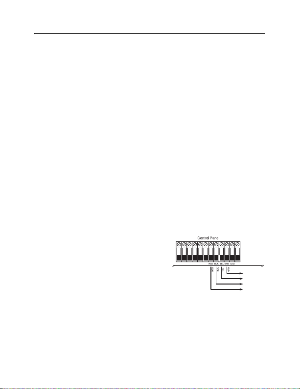
2.3 Connect the RF5132-433 Receiver
CAUTION: Remove all power from the system while connecting modules to the Keybus.
Connect the RF5132-433 to the four-wire Keybus of the cont rol panel according to the following diagram.
After you have completed the wiring, reconnect the power to the
security system.
The RF5132-433 has a fifth terminal labeled ‘GND’, which should
remain unused.
Now that you have wired the RF5132-433, you should enroll and
program the wireless devices. See section 3 for instructions.
2.4 Tamper
The unit incorporates separate built-in wall and case tampers. The
tampers are disabled by default on the NA version (Default on EU version: Active). Section [90] option 3 and 4 can
enable or disable the tampers.
When properly installed the wall tamper will be depressed by the wall where the R F5132-433 is installed on. The wall
tamper activates when the unit is removed from the wall. The case tamper activates when the case is opened and
restores when the case is closed.
KEYBUS
TO
RF5132
5
Page 8

Section 3: Receiver Programming
Enroll & Program Devices
This section describes how to enroll and program:
• wireless devices using zones (WLS904PL-433, WLS906-433, WS4916, WLS912L-433, WLS914-433, WS4938,
WLS925L-433)
• wireless keys (WLS919-433, WS49X9)
For more information on these devices, read the instruction sheet included with each device.
3.1 Identified Wireless Keys
Reporting by the system of openings/closings by individual wireless keys and command output [*][7] activation by
wireless key buttons may be supported on certain control panels. To do this, the system will reserve access codes 17 –
32 for wireless keys 01-16 respectively. You must program one access code for each wireless key (using [*][5] access
code programming) for this feature to work correctly.
NOTE: Program these access codes on the system after you have connected the RF5132-433 to the Keybus (see
section 2.4).
Refer to your system Installation Manual for information on access code programming.
Opening/Closing By Wireless Key Reporting
NOTE: The Identified Wireless Key Closing option is only available with the PC5020, PC1616, PC1864, PC501X
v2.0 and higher, PC1555(MX), PC580/585 v2.0 and higher.
To enable the reporting of openings and closings by identified wireless keys:
• Make sure the control panel is v2.0 or higher
• Program a valid access code for each key
• Program a closing and opening reporting code for each key’s access code
• Turn off the Quick Arm option in section [015] option [4] of the control panel programming
To ensure that an unidentified wireless key cannot disarm the system, turn off section [017], option [1] (in the control
panel programming). This opti on is available in control panels with software version 2.1 or higher.
3.2 A Note about Electronic Serial Numbers (ESN)
An electronic serial number (ESN) is printed on each wireless device. ESNs are used to enroll the wireless devices with
the RF5132-433 receiver.
In order to reduce the occurrence of wireless devices with the same serial number, 6-digit serial numbers are printed on
the back of each wireless device. The 6-digit serial numbers include hexadecimal digits. For instructions on
programming hexadecimal numbers, see your system Installation Manual, Section 4: How to Program.
NOTE: 6-digit serial numbers are only supported on the following control panels: PC5020, PC1616, PC1832,
PC1864, PC501X v2.0 & higher, PC1555(MX), PC580/585.
3.3 Enroll Wireless Devices Using Zones
Enroll wireless devices which use zones (universal transmitters, motion detectors, smoke detectors, and panic
pendants):
1. At a system keypad, enter [*][8][Installer ’s code] to go into the installer’s programming section.
2. Enter programming section [804].
6
Page 9

3. Enter the 2-digit number corresponding to the zone the device is to occupy ([01] to [32]).
NOTE: Hardwired and wireless devices cannot be assigned to the same zone. PC5108 zone expander modules
occupy zones in 2 groups of 4 (e.g. zones 9-12 and zones 13-16). None of the zones assigned to a PC5108
module may be used for wireless devices. For more information on zone assignment, consult your system
Installation Manual.
4. Enter the devi ce ESN. The entry must be 6 digits.
5. The device is now enrolled on the system. Record the serial number and the assigned zone number in the
programming worksheets in the back of this manual.
6. Continue with steps 3 - 5 until you have enrolled all wireless devices.
7. To exit press [#].
NOTE: The devices will not work properly until you complete zone and partition programming (see section 4).
3.4 Enroll & Program Wireless Keys
For wireless keys to work on the system, you need to enroll them and then program the function buttons, if the default
values are not the functions desired. Wireless keys are not assigned to zones and require no zone programming. You
can enroll up to 16 wireless keys on the system.
Enroll Wireless Keys
1. Enter [*][8][Installer’s Code] to go to the installer’s programming section.
2. Enter programming section [804].
3. Enter a 2-digit number [41]-[56] to prog ram the wireless key serial number. These numbers correspond to wireless
key numbers 01- 16.
4. Enter the devi ce ESN. The entry must be six digits.
5. The key is now enrolled on the system. Record the serial number and the assigned slot number in the programming
worksheets in the back of this manual.
6. Repeat steps 3 - 5 until all wi reless keys have been enrolled.
7. (PC5020/PC1616/PC1832/PC1864/PC501X only) By default, all wireless keys are assigned to Partition
1. To assign keys to different partition, see programming section [69].
NOTE: A wireless key can only be assigned to one partition.
8. To exit press [#].
Programming the Wireless Keys Function Buttons
Wireless keys have four programmable function buttons. Default functions have been assigned, but you may program
other functions if desired. After the functions are programmed, when you press and hold one of the four buttons for one
second, the system will execute the programmed function.
For systems using partitions (PC5020/PC1616/PC1832/PC1864/PC501X only): All wireless keys
assigned to Partition 1 will have the four functions programmed in section [61]. All wireless keys assigned to Partition
2-8 will have the four functions programmed in section [62-68]. For example, if function button 1 in Section [61] is
programmed for Stay arming, then pressing the first button on any wireless key assigned to Partition 1 will Stay arm
Part itio n 1.
NOTE: Wireless keys will not work when the partition they are assigned to is being accessed for zone bypassing or
programming.
1. At a system keypad, enter [*][8][Installer’s Code].
2. Enter programming section [804].
7
Page 10

3. Enter programming section [61] to [68] for partitions 1 to 8.
4. For each of the 4 function buttons, enter the 2-digit number of the function you want to select. See the
programming worksheets in the back of this manual for a list of function key options.
5. Record your programming choices in the worksheets in the back of the manual.
6. To exit press [#].
3.5 RF5132-433 LEDs
The RF5132-433 v5.0 features two LEDs to help with the installation of devices and troubleshoot the operation of the
unit. In normal operation the LEDs will indicate if the signal received is from an enrolled device or not.
• The green LED will flash when receiving a signal from an en rolled device.
• The red LED will flash when receiving a signal from a non-enrolled device.
Alternatively, when the panel is in placement test mode, the green LED will only flash for the specific serial number
entered. All other signals (including signals from valid enrolled devices) will flash red.
3.6 Deleting Wireless Devices
To remove a wireless device from the system, follow the guideline for adding a wireless device. Program the ESN as
[000000]. The wireless device for the zone will be removed.
Now that you have enrolled all the wireless devices, you will need to program the system to
work properly with the devices. See section 4 for more information.
8
Page 11

Section 4: Other Programming
4.1 Program Zones and Partitions
Now that you have enrolled the wireless devices, you should complete all zone programming on the system. Although
the exact programming required varies depending on which control panel the RF5132-433 is connected to, you should
check that the following programming area s are completed correctly for each wireless zone:
• Enable zones and/or assign zones to one or more partitions (programming sections [202]-[205] or [202] to [265]
for the PC5020/PC1616/PC1864).
• Program the definition for each zone (programming sections [001]-[004]).
• Enable the wireless zone attribute for each wireless zone (PC580, PC1555, PC1616, PC1832, PC1864, PC501X
v2.0, PC5020 v3.0 and higher only) (sections [101]-[132]).
See your system Installation Manual, for more information on each of the above programming sections.
4.2 Enable RF5132-433 Supervision
The control panel will supervise the RF5132-433 receiver via the Keybus after at least one device has been enrolled on
the module (see section 3.2 “Enrolling Wireless Devices”).
To activate module supervision, after you enroll the first device(s):
1. Exit and then re-enter installer ’s programming
2. Enter programming section [902]. Wait approximately 1 minute.
3. To exit press [#].
The system will generate a General System Supervisory trouble if the module is removed from the Keybus. If you need
to remove the RF5132-433 module from an existing system, you will have to disable supervision of the RF5132-433.
NOTE: Deleting all devices from the RF5132-433 or defaulting the RF5132-433 will cause a supervisory fault
To disable RF5132-433 supervision:
1. Disconnect the RF5132-433 from the Keybus
2. Enter [*][8][Installer Code]
3. Enter [902]. The control panel will clear all supervision and re-scan the system for connected modules. The scan
will take approximately one minute.
4. To exit press [#].
To review which modules the control panel is currently supervising:
1. Enter [*][8][Installer’s Code]
2. Enter [903] to display all modules. On a LED 32 zone keypad, light [17] will indicate that the RF5132-433 is
present on the system. On LCD keypads, scroll until the module name appears on the display.
3. To exit press [#].
If the RF5132-433 module does not show on the keypad, one of the following conditions may be present:
• the module is not connected properly to the Keybus
• there is a problem with the Keybus wiring run
• the module does not have enough power
• no devices have been enrolled on the RF5132-433
9
Page 12

4.3 Enable Supervision of Wireless Zones
NOTE: (for PC5010 v1.x control panels only) In order for wireless zones to be supervised, you must enable Double
End of Line (DEOL) supervision in the PC5010 control panel. For more information, refer to your Installation
Manual.
NOTE: (PC5020, PC1616, PC1832, PC1864, PC501X, PC1555, PC580 v2.0 and higher only) For wireless
supervision to work, you must enable the wireless zone attribute on all wireless zones (sections [101] to [132],
option [8] ON).
Wireless Supervisory Window
Each wireless device (excluding wireless keys) will send a supervisory signal periodically. If the receiver does not receive
a signal within the time programmed for the Wireless Supervisory Window, it will generate a supervisory fault.
To program the wireless supervisory window:
1. Enter [*][8][Installer Code] to enter Installer Programming.
2. Enter [804] to enter the RF5132-433 Module Programming.
3. Enter section [81].
4. Enter the time period for the supervisory window. The window is programmed in 15 minute increments. The default
programming is:
• 96 (x15minutes), which is equal to 24 hours for NA version, or
• 10 (x15minutes), which is equal to 2.5 hours for EU version.
Valid entries are (10) to (96), equal to 2.5 to 24 hours.
5. To exit press [#].
NOTE: Supervision must be enabled for RF Delinquency.
Disable/Enable Zone Supervision
All wireless zones have supervision enabled by default. To disable supervision for any zone, enter the following at any
system keypad:
1. Enter [*][8][Installer Code] to enter Installer Programming.
2. Enter [804] to enter the RF5132-433 Module Programming.
3. Enter sections [82], [83], [84] and [85]. Enable or disable supervision for each wireless zone by turning each
relevant option on or off.
4. To exit press [#].
4.4 RF Jam Detect Zone
For RF jamming detection to work, you must select an unused zone to be used as the RF Jam Detect zone. When the
receiver detects an attempt to jam the RF signal, the RF Jam Detect zone will be violated and the system will generate
a tamper signal. When the jamming signal is gone, the RF Jam Detect zone closes and the system sends a tamper
restore signal.
To enable RF jamming detection by zone:
1. Enter [*][8] [Installer’s Code].
2. Enter programming section [804].
3. Select an unused zone to be the RF Jam Detect zone. Enter the 2-digit number ([01] to [32]) of the RF Jam Detect
zone on the keypad, then program the serial number as [200000].
4. Enter section [93]. Enter the 2-digit number of the RF Jam Detect zone ([01] t o [32]) in the programming section.
10
Page 13

5. Disable supervision for the RF Jam detect zone by turning the relevant option off in section [82], [83], [84] or [85].
(See section 4.3 for more information.)
6. RF jamming detection is now enabled. To exit Installer programming, press [#].
NOTE: For UL Listed installations, the RF Jam feature must be enabled - Section [804], subsection [90], Option [7]
OFF. Ensure the wireless bit is enabled and jam bit in section [90] is disabled.
4.5 RF5132-433 Software Default
Returning the RF5132-433 programming to factory default settings is a quick way to remove all the enrolled devices
from the system and reset all the programming in section [804].
NOTE: Performing this procedure will not change any programming sections except [804]. Resetting the control
panel to factory default settings will not return the RF5132-433 module to factory default settings.
To restore the RF5132-433 programming to the factory default settings:
1. Enter [*][8] [Installer’s Code].
2. Enter programming section [996].
3. Enter the Installer ’s Code, followed by [996] again. The software for the RF5132-433 will be restored to its factory
default settings.
4. To continue programming the unit, exit installer’s programming by pressing [#] and then re-enter installer’s
programming by entering [*][8] [Installer’s Code].
For instructions on restoring the default programming of the control panel or any other connected module, see your
system Installation Manual.
4.6 Deleting Wireless Devices
To remove a wireless device from the system, follow the guideline for enrolling a wireless device (see section 3.2).
Program the ESN as [000000]. The wireless device for the zone will be removed.
NOTE: You may need to remove power from the panel in order to clear troubles caused by deleted zones.
Now that you have completed all RF5132-433 related programming, you can test and mount
the receiver and devices. See section 5 for more information.
11
Page 14

Section 5: Testing & Mounting
5.1 Test the Reception of Wireless Devices
It is very important to test the proposed placement of each wireless device before it is mounted. Following these steps
will test the signal strength between the RF5132-433 and the wireless devices.
You can test all of the devices together (global placeme nt testing) or test each device individually. To test all the devices
together, see ‘Testing All Wireless Devices Together’ below. To test wireless devices individually, see ‘Testing Individual
Devices’.
NOTE: After you have enrolled the wireless devices, you must exit and then re-enter Installer’s Programming at least
once before you can perform a placement test.
Testing All Wireless Devices Together:
1. Temporarily put the wireless devices in the places you want to mount them.
2. At a system keypad, enter [*][8][Installer Code].
3. Enable the Global Module Placement test by entering section [804]. Then enter sub-section [90] and turn on
option [8].
4. Press [#] twice.
5. Enter programming section [904], then enter [01].
6. Activate one of the devices being tested until a result is displayed on the keypad or sounded by the keypad or bell:
Motion Detectors: To perform a Placement Test on the WLS904P-433, remove the detector from the back
plate and then replace it. Once the detector is replaced on the back plate the LED on the detector will flash rapidly 5
times (4 times for the WLS914-433) to indicate that it has sent a transmission. The panel will show and/or sound
the result of the placement test on the keypad. To perform a 2nd and 3rd test, repeat this procedure. Carefully
replace the backplate onto the detector, ensuring that “TOP” is facing upward, or you may
damage the tamper switch.
NOTE: When you remove the detector from the backplate (tamper the unit), the detector will also be put into
“Detector Walk Test” mode. While in Walk Test mode the detector will activate the LED when motion is
detected. The detector will also send a signal to the receiver 5 seconds after motion is detected, indicated by 5
rapid flashes by the LED. The LED will only work in this fashion for 10 motion detections after a tamper/restore.
Note that the panel will ignore these transmission signals with respect to a placement test. The only way in
which the panel will acknowledge a placement test is if the backplate has, each time, been removed and
restored.
Smoke Detector: Remove the detector from its backplate, wait 5 seconds and re-attach it, or hold a magnet
near the raised line on the outer rim, then remove it.
Door/Window Transmitter: Open the contact by moving the magnet away from the unit. The keypad will
show/sound the test result. After the first test result has been generated (about 10 seconds) close the contact to
generate another test result. If the unit is attached to a door or a window, open and close the door or window to
activate the device.
Glassbreak Detector: Press and hold the test mode tab for 5 seconds. Release the test mode tab. The keypad
will display the test result.
12
Page 15

Read the test results at the keypad::
Result LED Keypad LCD Keypad Buzzer/Bell
Good Light 1 On Steady “Good” 1 Beep/Squawk
Bad Light 3 On Steady “Bad” 3 Beeps/Squawks
Activate the device until you get 3 ‘good’ results in a row.
You may mount the WLS devices where results were good.
Devices indicating a bad result must be moved to another location. You may only have to move the device a
few inches to correct a bad result.
Do not mount any device where a “bad” test result was indicated.
7. Go to the next device to be tested and activate it until the test result is displayed/sounded.
NOTE: Wait until the placement test of one device is shown/sounded before beginning to test the next
device.
Continue to test the devices until both the RF5132-433 and the devices are in good locations. If several
wireless devices produce ‘bad’ test results, you may need to move the RF5132-433 to a better location.
(See section 2.2 for tips on finding a location for the RF5132-433.)
8. To exit the placement test and return to installer programming, press [#] twice.
Testing Individual Devices:
1. Temporarily place the device where you want to mount it.
2. At a sys tem keypad, enter [*][8][Installer Code].
3. Enter programming section [904].
4. Ensure option 8 in section [90] is disabled.
5. Enter the 2-digi t zone number for the device to be tested.
6. Activate the device being tested until a result is displayed on the keypad or sounded by the keypad or bell.
(Same as step 5 in the Global Placement Test section, previous page.)
7. To test another device, press [#] once, then repeat steps 4 - 5. Continue to test the devices until both the
RF5132-433 and the devices are in good locations.
If several wireless devices produce ‘bad’ test results, you may need to move the RF5132-433 to a better
location. (See section 2.2 for tips on finding a location for the RF5132-4 33.)
8. To exit the placement test and i nstaller programming, press [#] twice.
Testing Individual Wireless Keys:
Do not use the individual device test described above to test the wireless keys. To ensure that the RF5132-433
receiver is receiving transmissions from these devices, use the function keys on these devices at several different
points in the installation.
5.2 Mount the RF5132-433 and Wireless Devices
When you have tested reception of the RF5132-433 with all the wireless devices (see section 5.1) and you have a
good mounting location, mount the RF5132-433:
1. Pull the Keybus wires through the hole at the bottom of the cabinet.
2. Mount the cabinet securely to the wall.
13
Page 16

Mount the Devices
If you have conducted the placement test described in section 5.1 and got 3 ‘good’ results in a row for each device,
you can mount the wireless devices. See the Installation Sheet for each device for mounting instructions.
Now that your RF5132-433 and wireless devices are mounted and working properly, read
section 6 for information on potential wireless trouble conditions, RF jamming signals, and
battery replacement.
14
Page 17

Section 6: Additional Notes
6.1 Trouble Conditions
The control panel always watches for possible trouble conditions. If a trouble condition occurs, the keypad “Trouble”
light will turn on and the keypad will beep. Press [*][2] to display the trouble conditions.
The following trouble conditions apply to the RF5132-433 and/or any enrolled devices.
• General System Tamper (on Power panels v.2.01 and below) - This trouble is generated when the RF5132-
433 detects an RF Jamming condition.
• General System Supervisory - This trouble will be generated if the panel loses communication with any
module connected to the Keybus. The event buffer will log a detailed description of the event.
• Device Low Battery - This trouble is generated when a wireless device exhibits a low battery condition. Press [7]
one, two, or three times to view which devices are experiencing battery failure. An LED keypad will indicate battery
failure using zone lights 1 to 8.
• Zone Tamper - This trouble is generated when an enrolled wireless device is removed from its mounting location.
• Zone Fault - Each wireless device will send a supervisory signal every 64 minutes (15 minutes for EU). If the
receiver does not receive a signal within the time programmed for the Wireless Supervisory Window, it will generate
a zone fault.
• RF Delinquency (EU only) - Each wireless zone will send a supervisory signal every 15 minutes. If the receiver
does not receive a signal within 15 minutes, it will generate a RF Delinquency Trouble for that zone. This condition
exists only on PC1614/PC1832/PC1864 panels v4.1.
6.2 Jamming Signal Detection
The RF5132-433 receiver detects jamming signals that can prevent the receiver from properly receiving transmissions
from enrolled devices. See section 4.4 “RF Jam Detect Zone” for information on jamming signal detection
programming.
NOTE: For UL Listed installations, the RF Jam feature must be enabled - Section [804], subsection [90],
Option [7] OFF.
6.3 Wireless Zone Low Battery Transmission
Within any transmission, the device will indicate the status of the battery. If a battery is low, the system will indicate a
Device Low Battery trouble.
The system will delay reporting the event to the central station for the number of days programmed for Zone Low
Battery Transmission Delay in section [370] of the panel. This will prevent unnecessary reporting of the event if
the user has been instructed on how to replace batteries.
Replacing Batteries in Wireless Devices
1. Refer to the battery installation instructions on the installation sheet of each device. Be sure to note the proper
orientation of the batteries as you install them.
2. When the fresh batteries are in place and the device tamper is restored, the device sends a battery trouble restoral
signal to the RF5132-433. The battery trouble is now clear and the device should function normally.
NOTE: When batteries in one device need to be replaced, the batteries in all devices may need to be replaced
at the same time.
15
Page 18

Section 7: Troubleshooting
The RF5132-433 v5.0 features two LEDs to help and with the installation of devices troubleshoot the operation of the
unit. In normal operation the LEDs will indicate if the signal received is from an enrolled device or not.
• The green LED will flash when receiving a signal from an en rolled device.
• The red LED will flash when receiving a signal from a non-enrolled device.
Alternatively, when the panel is in placement test mode, the green LED will only flash for the specific serial number
entered. All other signals (including signals from valid enrolled devices) will flash red.
1. When I enter the 2-digit zone number for adding a wireless device, the keypad gives me
a long beep.
ESNs can be entered only when a RF5132-433 wireless receiver is connected to the Keybus. See section 2 for
instructions on setting up and wiring the RF5132-433 module.
2. I have entered the ESN for the device but when I violate the device, the zone does not
show open on the keypad.
Check the following:
• Ensure the ESN has been entered correctly
• Ensure that the zone is enabled for the partition (if partition programming is used).
• Ensure that the wireless zone is not assigned to a zone used by PC5108 modules, an on-board zone, or a keypad
zone.
• Ensure that the zone is programmed for something other than “Null Operation”, and that the wireless zone attribute
is turned on.
3. When I try a module placement test I get no result or ‘bad’ results.
Check the following (see sections 5.1 and 5.2 for more information on testing devices):
• Verify that you are testing the correct zone.
• Verify that the correct ESN was entered when the device was enrolled.
• Verify that the device is in range of the RF5132-433. Try testing the device in the same room as the receiver.
• Confirm that the RF5132-433 is properly connected to the Keybus (see section 2 for RF5132-433 set up and wiring
instructions).
• Check that you are testing the zone correctly (see sections 5.1 and 5.2 for testing instructions).
• Check that the batteries are working and installed correctly.
• Look for large metal objects that may be preventing the signal from reaching the RF5132-433.
The device must be located where consistent ‘good’ results are obtained. If several devices show ‘bad’ results, move the
receiver. See section 2.2 for tips on choosing a mounting location for the RF5132-433.
4. The LED on the motion detector does not turn on when I walk in front of the unit.
The LED is for walk test purposes only. See your Wireless PIR Instruction Sheet for walk test instructions.
16
Page 19

Section 8: Programming Worksheets
[804] RF5132-433 Wireless Expansion Programming
• 6-digit entry is required. See Section 3.2 “A note on Electronic Serial Numbers” for details on programming 6-digit
serial numbers.
Zone Serial Numbers
Default = 000000
[01] Zone 1
[02] Zone 2
[03] Zone 3
[04] Zone 4
[05] Zone 5
[06] Zone 6
[07] Zone 7
[08] Zone 8
[09] Zone 9
[10] Zone 10
[11] Zone 11
[12] Zone 12
[13] Zone 13
[14] Zone 14
[15] Zone 15
[16] Zone 16
Wireless Key Serial Numbers
Default = 000000
[41] Key 01
[42] Key 02
[43] Key 03
[44] Key 04
[45] Key 05
[46] Key 06
[47] Key 07
[48] Key 08
l_____l_____l_____l_____l_____l_____l
l_____l_____l_____l_____l_____l_____l
l_____l_____l_____l_____l_____l_____l
l_____l_____l_____l_____l_____l_____l
l_____l_____l_____l_____l_____l_____l
l_____l_____l_____l_____l_____l_____l
l_____l_____l_____l_____l_____l_____l
l_____l_____l_____l_____l_____l_____l
l_____l_____l_____l_____l_____l_____l
l_____l_____l_____l_____l_____l_____l
l_____l_____l_____l_____l_____l_____l
l_____l_____l_____l_____l_____l_____l
l_____l_____l_____l_____l_____l_____l
l_____l_____l_____l_____l_____l_____l
l_____l_____l_____l_____l_____l_____l
l_____l_____l_____l_____l_____l_____l
l_____l_____l_____l_____l_____l_____l
l_____l_____l_____l_____l_____l_____l
l_____l_____l_____l_____l_____l_____l
l_____l_____l_____l_____l_____l_____l
l_____l_____l_____l_____l_____l_____l
l_____l_____l_____l_____l_____l_____l
l_____l_____l_____l_____l_____l_____l
l_____l_____l_____l_____l_____l_____l
[17] Zone 17
[18] Zone 18
[19] Zone 19
[20] Zone 20
[21] Zone 21
[22] Zone 22
[23] Zone 23
[24] Zone 24
[25] Zone 25
[26] Zone 26
[27] Zone 27
[28] Zone 28
[29] Zone 29
[30] Zone 31
[31] Zone 31
[32] Zone 32
[49] Key 09
[50] Key 10
[51] Key 11
[52] Key 12
[53] Key 13
[54] Key 14
[55] Key 15
[56] Key 16
l_____l_____l_____l_____l_____l_____l
l_____l_____l_____l_____l_____l_____l
l_____l_____l_____l_____l_____l_____l
l_____l_____l_____l_____l_____l_____l
l_____l_____l_____l_____l_____l_____l
l_____l_____l_____l_____l_____l_____l
l_____l_____l_____l_____l_____l_____l
l_____l_____l_____l_____l_____l_____l
l_____l_____l_____l_____l_____l_____l
l_____l_____l_____l_____l_____l_____l
l_____l_____l_____l_____l_____l_____l
l_____l_____l_____l_____l_____l_____l
l_____l_____l_____l_____l_____l_____l
l_____l_____l_____l_____l_____l_____l
l_____l_____l_____l_____l_____l_____l
l_____l_____l_____l_____l_____l_____l
l_____l_____l_____l_____l_____l_____l
l_____l_____l_____l_____l_____l_____l
l_____l_____l_____l_____l_____l_____l
l_____l_____l_____l_____l_____l_____l
l_____l_____l_____l_____l_____l_____l
l_____l_____l_____l_____l_____l_____l
l_____l_____l_____l_____l_____l_____l
l_____l_____l_____l_____l_____l_____l
17
Page 20

Wireless Key Function Key Options
Entry Key Description Entry Key Description
00 Null Key 16 [*][0] Quick Exit
01-02 For Future Use 17 [*][1] Reactivate Stay/Away
03 Stay Arm 18 For Future Use
04 Away Arm 19 [*][7][3] Command Output #3
05 [*][9] No-Entry Arm 20 For Future Use
06 Chime ON/OFF 21 [*][7][4] Command Output #4
07 [*][6][---][4] System Test 22-26 For Future Use
08-12 For Future Use 27 Disarm (OFF)
13 [*][7][1] Command Output #1 28 For Future Use
14 For Future Use 29 Auxiliary Alarm
15 For Future Use 30 Panic Alarm
Wireless Key Options
Partition 1 Wireless Key Options
[61] Function Key 1 Default: 03 l____l____l Function Key 3 Default: 27 l____l____l
Function Key 2 Default: 04 l____l____l Function Key 4 Default : 30 l____l____l
Partition 2 Wireless Key Options
[62] Function Key 1 Default: 03 l____l____l Function Key 3 Default: 27 l____l____l
Function Key 2 Default: 04 l____l____l Function Key 4 Default : 30 l____l____l
Partition 3 Wireless Key Options
[63] Function Key 1 Default: 03 l____l____l Function Key 3 Default: 27 l____l____l
Function Key 2 Default: 04 l____l____l Function Key 4 Default : 30 l____l____l
Partition 4 Wireless Key Options
[64] Function Key 1 Default: 03 l____l____l Function Key 3 Default: 27 l____l____l
Function Key 2 Default: 04 l____l____l Function Key 4 Default : 30 l____l____l
Partition 5 Wireless Key Options
[65] Function Key 1 Default: 03 l____l____l Function Key 3 Default: 27 l____l____l
Function Key 2 Default: 04 l____l____l Function Key 4 Default : 30 l____l____l
Partition 6 Wireless Key Options
[66] Function Key 1 Default: 03 l____l____l Function Key 3 Default: 27 l____l____l
Function Key 2 Default: 04 l____l____l Function Key 4 Default : 30 l____l____l
18
Page 21

Partition 7 Wireless Key Options
[67] Function Key 1 Default: 03 l____l____l Function Key 3 Default: 27 l____l____l
Function Key 2 Default: 04 l____l____l Function Key 4 Default : 30 l____l____l
Partition 8 Wireless Key Options
[68] Function Key 1 Default: 03 l____l____l Function Key 3 Default: 27 l____l____l
Function Key 2 Default: 04 l____l____l Function Key 4 Default : 30 l____l____l
[69] Wireless Keys (1-16) Partition Assignments (Default = 01)
Wireless Key 01 l____l____l Wireless Key 09 l____l____l
Wireless Key 02 l____l____l Wireless Key 10 l____l____l
Wireless Key 03 l____l____l Wireless Key 11 l____l____l
Wireless Key 04 l____l____l Wireless Key12 l____l____l
Wireless Key 05 l____l____l Wireless Key13 l____l____l
Wireless Key 06 l____l____l Wireless Key14 l____l____l
Wireless Key 07 l____l____l Wireless Key 15 l____l____l
Wireless Key 08 l____l____l Wireless Key 16 l____l____l
Supervision
[81] Wireless Supervisory Window (Default = 96)
l____l____l The window is p rogrammed in 15 minute increments.
The default programming is:
• 96 (x15minutes), which is equal to 24 hours for NA version, or
• 10 (x15minutes), which is equal to 2.5 hours for EU version.
Valid entries are (10) to (96), equal to 2.5 to 24 hours.
[82] Zone Device Supervision Options (1-8)
Default = ON Option ON Option OFF
l____l Option 1 Zone 01 Supervision Enabled Disabled
l____l Option 2 Zone 02 Supervision Enabled Disabled
l____l Option 3 Zone 03 Supervision Enabled Disabled
l____l Option 4 Zone 04 Supervision Enabled Disabled
l____l Option 5 Zone 05 Supervision Enabled Disabled
l____l Option 6 Zone 06 Supervision Enabled Disabled
l____l Option 7 Zone 07 Supervision Enabled Disabled
l____l Option 8 Zone 08 Supervision Enabled Disabled
19
Page 22

[83] Zone Device Supervision Options (9-16)
Default = ON Option ON Option OFF
l____l Option 1 Zone 09 Supervision Enabled Disabled
l____l Option 2 Zone 10 Supervision Enabled Disabled
l____l Option 3 Zone 11 Supervision Enabled Disabled
l____l Option 4 Zone 12 Supervision Enabled Disabled
l____l Option 5 Zone 13 Supervision Enabled Disabled
l____l Option 6 Zone 14 Supervision Enabled Disabled
l____l Option 7 Zone 15 Supervision Enabled Disabled
l____l Option 8 Zone 16 Supervision Enabled Disabled
[84] Zone Device Supervision Options (17-24)
Default = ON Option ON Option OFF
l____l Option 1 Zone 17 Supervision Enabled Disabled
l____l Option 2 Zone 18 Supervision Enabled Disabled
l____l Option 3 Zone 19 Supervision Enabled Disabled
l____l Option 4 Zone 20Supervision Enabled Disabled
l____l Option 5 Zone 21 Supervision Enabled Disabled
l____l Option 6 Zone 22 Supervision Enabled Disabled
l____l Option 7 Zone 23 Supervision Enabled Disabled
l____l Option 8 Zone 24 Supervision Enabled Disabled
[85] Zone Device Supervision Options (25-32)
Default = ON Option ON Option OFF
l____l Option 1 Zone 25Supervision Enabled Disabled
l____l Option 2 Zone 26 Supervision Enabled Disabled
l____l Option 3 Zone 27 Supervision Enabled Disabled
l____l Option 4 Zone 28 Supervision Enabled Disabled
l____l Option 5 Zone 29 Supervision Enabled Disabled
l____l Option 6 Zone 30 Supervision Enabled Disabled
l____l Option 7 Zone 31 Supervision Enabled Disabled
l____l Option 8 Zone 32 Supervision Enabled Disabled
20
Page 23

[90] Other Options
Default Option(s) Option ON Option OFF
NA EU
Off Off 1-2 For Future Use
On Off 3 Wall Tamper Disabled Wall Tamper Enabled
On Off 4 Case Tamper Disabled Case Tamper Enabled
On Off 5 RF Delinquency Disabled RF Delinquency Enabled
Off Off 6 For Future Use
On Off 7 RF Jam Detect Disabled RF Jam Detect Enabled
Off Off 8 Global Placement Test Individual Placement Test
RF Jamming Detection
[93] RF Jam Detect Zone
(Default = 00)
l____l____l Select an unused zone that will be violated when a jamming signal is detected
(Valid entries = 01 - 32, 00 = RF Jam detect disabled.)
NOTE: For UL Listed installations, the RF Jam feature must be enabled - Section [804], subsection [90], Option
[7] OFF.
NOTE: For DD243 installations, the RF delinquency feature should be enabled - Section [804], subsection [90],
Option [5] OFF.
21
Page 24

ATTENTION à lire attentivement
Note pour les installateurs
Cette mise en garde contient des informations vitales. En tant que seul
individu en contact avec les utilisateurs du système, c’est à vous
qu’incombe la responsabilité d’attirer l’attention des utilisateurs du
système sur chaque élément de cette mise en garde.
Pannes de Système
Ce système à été soigneusement conçu pour être aussi efficace que possible. Toutefois, dans des circonstances, où il y a feu, cambriolage ou
autre genre d’urgences, il ne peut pas fournir de protection. Tout
système d’alarme quel qu’il soit peut être saboté ou peut ne pas fonctionner comme prévu pour plusieurs raisons. Certaines de ces raisons
sont notamment :
• Mauvaise Installation
Un système de sécurité doit être correctement installé pour fournir une
protection adéquate. Chaque installation doit être évaluée par un professionnel de la sécurité pour s’assurer que tous points d’accès et aires sont
couvertes. Serrures et loquets sur les fenêtres et portes doivent être bien
fermés et fonctionner comme prévu. Les matériels de construction des
fenêtres, portes, murs, plafonds et autres doivent assez solides pour
assurer le niveau de protection attendue. Une réévaluation doit être
effectuée pendant et après toute construction. Une évaluation par les
sapeurs-pompiers et/ou les services de police est grandement recommandée si ce service est offert.
• Connaissances Criminelles
Ce système contient des fonctions de sécurité reconnues efficaces au
moment de la fabrication. Il est possible que des personnes ayant des
intentions criminelles élaborent des techniques qui réduisent l’efficacité
de ces fonctions. Il est important qu’un système sécurité soit réexaminé
périodiquement pour assurer que ces fonctions restent fonctionnelles et
pour les actualiser ou les remplacer si elles n’assurent plus la protection
attendue.
• Accès par des Intrus
Des intrus peuvent entrer par un point d’accès non protégé en contournant une unité de détection, échapper à une détection en se déplaçant
dans une zone à couverture insuffisante, déconnecter une unité d’alerte,
ou interférer avec le système ou empêcher son fonctionnement normal.
• Panne de Courant
Les unités de Contrôle, les détecteurs d’intrusion, les détecteurs de
fumée et bien d’autres dispositifs de sécurité nécessitent une alimentation électrique pour fonctionner normalement. Si un dispositif fonctionne à partir de piles, il est possible que les piles faiblissent. Même si
les piles ne sont pas faibles, elles doivent être changées, en bonne condition et installées correctement. Si un dispositif ne fonctionne que par
courant électrique, toute interruption, même brève, rendra ce dispositif
inopérant pendant la durée de la coupure de courant. Les coupures de
courant, quelle qu’en soit la durée, sont souvent accompagnées par des
fluctuations de voltage qui peuvent endommager l’équipement électronique tel qu’un système de sécurité. Après qu’une coupure de courant
s’est produite, effectuez immédiatement un test complet du système
pour vous assurer que le système fonctionne correctement
• Panne de Piles Remplaçables
Les transmetteurs sans fils de ce système ont été conçus pour fournir
plusieurs années d’autonomie de piles sous des conditions normales. La
durée de vie de la pile dépend de l’environnement du dispositif, de utilisation et du type de pile. Les conditions ambiantes telles que l’humidité
élevée, des températures très élevée ou très bases, ou de grosses différences de température peuvent réduire la durée de vie de la pile. Bien
que chaque dispositif de transmission possède un dispositif de surveillance de pile faible et qu’il indique quand les piles ont besoin d’être
remplacée, il peut ne pas fonctionner comme prévu. Des tests et un
entretien régulier garderont le système dans de bonne condition de fonctionnement.
• Limites de fonctionnement des Dispositifs de Fréquence Radio
(Sans Fils)
Les signaux peuvent ne pas atteindre le récepteur dans toutes les circonstances qui pourraient inclure objets métalliques placés sur ou à côté du
chemin radio ou blocage délibéré ou autre interférence du signal radio
commis par inadvertance.
• Les Utilisateurs du Système
Un utilisateur peut ne pas être en mesure de faire fonctionner un interrupteur de panique ou d’urgence à cause d’une invalidité permanente ou
temporaire, d’une incapacité d’atteindre le dispositif à temps, ou d’un
manque de connaissance de la bonne fonction. Il est important que tous
les utilisateurs du système soient formés sur le bon fonctionnement du
système d’alarme pour qu’ils sachent comment réagir quand le système
indique une alarme.
• Détecteurs de Fumée
Les détecteurs de fumée qui font partie du système peuvent ne pas bien
alerter les occupants d’un endroit en feu pour un certains nombre de rai-
sons, en voici quelques une. Le détecteurs de fumée peuvent avoir été
mal installés ou positionnés. La fumée peut ne pas pouvoir atteindre le
détecteurs de fumée, par exemple : un incendie dans une cheminée,
murs ou toits, ou de l’autre côté de portes fermées. Les détecteurs de
fumée peuvent ne pas détecter la fumée provenant d’incendies à un
autre niveau de la résidence ou du bâtiment.
Tous les incendies différent par la quantité de fumée produite et le taux
de combustion. Les détecteurs de fumée ne peuvent pas détecter de la
même manière tous les types d’incendies. Les détecteurs de fumée ne
fournissent pas d’avertissement opportun d’un incendie causé par une
imprudence ou un manque de sécurité tels que fumer dans le lit, explosions violentes, fuites de gaz, mauvais rangement de produits inflammables, circuits électriques surchargés, enfants jouant avec des
allumettes.
Même si le détecteur de fumée fonctionne comme prévu, dans certaines
circonstances il n’y a pas assez de préavis pour permettre à tous les
occupants de s’enfuir à temps pour éviter blessure ou mort.
• Détecteurs de mouvement
Les détecteurs de mouvement ne peuvent détecter le mouvement que
dans les zones désignées, conformément aux instructions d’installation.
Ils ne peuvent pas distinguer entre intrus et occupants. Les détecteurs de
mouvement ne fournissent pas de protection de zone volumétrique. Ils
ont de multiples rayons de détection et les mouvements ne peuvent être
détectés que dans des zones non obstruées et couvertes par ces rayons.
Ils ne peuvent détecter les mouvements qui se produisent derrière les
murs, plafonds, sol, portes fermées, cloisons vitrées, portes vitrées ou
fenêtres. Tout type de problème qu’il soit intentionnel ou non tels camouflage, peinture ou vaporisation de matériel sur les lentilles, miroirs,
fenêtres ou toute autre partie du système de détection l’empêchera de
son fonctionner normalement.
Les Détecteurs de mouvement à infra-rouge passif fonctionnent en
détectant les changements de température. Cependant leur fonctionnement peut être inhibé quand la température ambiante s’approche ou
dépasse la température du corps ou s’il y a des sources de chaleur intentionnelles ou non intentionnelles dans de la zone de détection ou à côté
de celle-ci. Quelques une de ces sources de chaleur peuvent être chauffages, radiateurs, fours, barbecues, cheminées, lumière du soleil, éclairages, etc.
• Dispositifs d’Avertissement
Les dispositifs d’avertissement tels que sirènes, cloches, klaxons ou
lumières stroboscopiques n’avertissent pas les gens ou ne réveillent pas
quelqu’un qui dort s’il y a un mur ou une porte fermée. Si les dispositifs
d’avertissement sont placés à un autre niveau de la résidence ou du
local, alors il est que probable que les occupants ne seront pas alertés ou
réveillés. Les dispositifs d’avertissement audibles peuvent interférer
avec d’autres sources de bruit tels stéréo, radios, télévisions, climatisations ou autres unités électriques, ou la circulation. Les dispositifs
d’avertissement audibles, même bruyants, ne peuvent pas être entendus
par une personne malentendante.
• Lignes Téléphoniques
Si les lignes téléphoniques sont utilisées pour transmettre des alarmes,
elles peuvent être hors d’usage ou occupées pendant une certaine période de temps. Un intrus peut également couper la ligne téléphonique ou
provoquer son dérangement par des moyens plus sophistiqués parfois
difficiles à détecter.
• Insuffisance de temps
Ils peut y avoir des circonstances où le système fonctionne comme
prévu, mais où les occupants ne seront pas protégés à cause de leur
incapacité à répondre aux avertissements dans un temps alloué. Si le
système est connecté à un poste de surveillance, l’intervention peut ne
pas arriver à temps pour protéger les occupants ou leurs biens.
• Panne d’un élément
Bien que tout les efforts ont été faits pour rendre le système aussi fiable
que possible, le système peut mal fonctionner à cause de la panne d’un
élément.
•Test Insuffisant
La plupart des problèmes qui pourraient empêcher un système d’alarme
de fonctionner normalement peuvent être découverts en testant et entretenant le système régulièrement. L’ensemble du système devrait être
testé hebdomadairement et immédiatement après une entrée par effraction, une tentative d’entrée par effraction, un incendie, une tempête, un
tremblement de terre, un accident ou toute sorte de construction à
l’intérieur des lieux. Le test doit comporter tous les dispositifs de détection, claviers, consoles, dispositifs d’indication d’alarme et tout autre
dispositif de fonctionnement qui font partie du système.
n Sécurité et Assurance
Sans tenir compte de ses capacités, un système d’alarme n’est pas un
substitut d’assurance sur la propriété ou d’assurance vie. Un système
d’alarme n’est pas un substitut de propriétaire, locataires ou autres occupants pour agir prudemment afin d’empêcher ou de minimiser les effets
nuisibles d’une situation d’urgence.
22
Page 25

GARANTIE LIMITÉE
La société Digital Security Controls garantit le produit contre toutes
défectuosités matérielles et d’assemblage dans des conditions normales
d’utilisation, à l’acheteur original, pendant une période de douze mois à
partir de la date d’achat. Dans l’application de cette garantie, la société
Digital Security Controls s’engage, à son choix, à réparer ou à remplacer tout matériel défectueux dès son retour à un dépôt de réparation,
sans frais de main d’oeuvre et matériels. Tout remplacement et/ou réparation sont garantis pendant le reste de la durée de la garantie originale
ou quatre vingt dix (90) jours, ou l’une ou l’autre est la plus longue. Le
propriétaire original doit avertir la société Digital Security Controls par
courrier que le matériel ou l’assemblage sont défectueux ; dans tous les
cas, cette notification doit être reçue avant l’expiration de la période de
garantie.
Garantie Internationale
La garantie pour les clients internationaux est la même que pour tous les
clients au Canada et aux Etats-Unis, sauf que la société Digital Security
Controls ne sera pas responsable des frais de douanes, taxes, ou TVA
qui pourraient être dus.
Procédure pour la Garantie
Pour obtenir un service sous garantie, veuillez retourner les produit(s)
en question au point d’achat. Tous les distributeurs autorisés et vendeurs
ont un programme de garantie. Quiconque retourne des marchandises à
la société Digital Security Controls doit tout d’abord obtenir un numéro
d’autorisation. La société Digital Security Controls n’acceptera aucun
envoi pour lequel une autorisation préalable n’aura pas été obtenue.
Conditions d’annulation de la Garantie
Cette garantie ne s’applique qu’aux vices de matériels et d’assemblage
liés à une utilisation normale. Elle ne couvre pas:
• dommage encouru lors de l’expédition ou la manutention;
• dommage causé par un désastre tel qu’un incendie, inondation, vent,
tremblement de terre ou foudre ;
• dommage dû à des causes hors du contrôle de la société Digital Security Controls tel que voltage excessif, choc mécanique ou dommage
des eaux ;
• dommage causé par attachement non autorisé, changements, modifications ou objets étrangers ;
• dommage causé par périphériques (à moins que les périphériques ne
soient fournis par la société Digital Security Controls) ;
• défauts causés par l’impossibilité de fournir un environnement
d’installation adapté aux produits ;
• dommage causé par l’utilisation des produits pour des usages autres
que ceux pour lesquels ils ont été conçus
• dommage pour mauvais entretien ;
• dommage provenant de tout autre mauvais traitement, mauvaise
manutention ou mauvaise utilisation des produits.
S’il y a un problème de réparation du produit après un nombre raisonnable de tentatives au titre de la présente garantie, les obligations contractuelles de la société Digital Security Controls seront limitées au
remplacement du produit, comme seule réparation de l’inobservation de
la garantie. En aucun cas la Société Digital Security Controls ne sera
responsable des dommages particuliers, accidentels ou indirects basés
sur l’inobservation de la garantie, une rupture de contrat, une négligence, une responsabilité stricte ou sur toute autre théorie juridique. De
tels dommages incluent, mais ne sont limités à, une perte de profit, une
perte de produit ou tout autre équipement associé, au coût de capital, au
coût de remplacement de l’équipement, à l’aménagement ou services, à
l’indisponibilité, au temps de rachat, aux réclamations des tiers, notamment les clients, aux dommages et intérêts à la propriété, etc .
Stipulation d’exonération de garanties
Cette garantie contient l’entière garantie et remplace toutes les autres
garanties, qu’elles soient explicites ou implicites (notamment toutes les
garanties implicites de marchandise ou aptitude pour un usage particulier) et de toutes autres obligations ou responsabilités de Digital Security
Controls. Digital Security Controls n’assume et n’autorise aucune autre
personne prétendant agir en son nom de modifier ou changer cette
garantie, n’assume pour cela aucune autre garantie ou responsabilité
concernant ce produit.
Cette stipulation d’exonération de garanties et garantie restreinte sont
gouvernées par les lois de la province de l’Ontario, Canada.
ATTENTION: Digital Security Controls recommande que la totalité
du système soit testé régulièrement. Toutefois, même si vous faites des
essais périodiques, il peut arriver que le fonctionnement du produit ne
soit pas conforme aux spécifications en raison notamment, mais pas
exclusivement, d’interventions criminelles ou de panne de courant.
Réparations en dehors de la Garantie
Digital Security Controls réparera à son choix ou remplacera en dehors
de la garantie les produits renvoyés à son usine dans les conditions suivantes. Quiconque retourne des produits à Digital Security Controls doit
d’abord obtenir un numéro d’autorisation. Digital Security Controls
n’acceptera aucun envoi quel qu’il soit, pour lequel une autorisation
préalable n’aura pas été obtenue.
Les produits que Digital Security Controls juge être réparables seront
réparés et renvoyés. Les frais prédéterminés par Digital Security Controls, et sujets à un rajustement périodique, seront facturés pour chaque
unité réparée.
Les produits que Digital Security Controls juge ne pas être réparables
seront remplacés par le produit équivalent le plus proche disponible à ce
moment. Le prix du marché en cours du produit de remplacement sera
facturé pour chaque unité de remplacement.
23
Page 26

Table de Matières
Section 1: Introduction .............................25
1.1 Ce qu’il y a de Nouveau da ns la Version 5.X ......25
1.2 Comment Utiliser ce Manuel .............................25
1.3 Spécifications et Caractéristiques ....................... 25
1.4 Dispositifs Sans Fil Compatibles .................. .......26
1.5 Instructions de Sécurité .....................................26
Section 2: Configuration et Câblage du
RF5132-433 ...............................................27
2.1 Déballer le RF5132-433 .................................. 27
2.2 Choisir un Local de Montage pour le
RF5132-433 .................................................... 27
2.3 Connecter le Récepteur RF5132-433 ................. 27
2.4 Violation ..........................................................27
Section 3: Programmation du Récepteur...28
3.1 Touches Identifiées du Clavier Sans Fil................28
3.2 Remarque sur les Numéros de Série
Électroniques (ESN)................. ..........................28
3.3 Enregistrer les Dispositifs Sans Fil en Utilisant
Zones................... .............................................28
3.4 Enregistrer et Programmer les Claviers Sans Fil ...29
3.5 Voyants du RF5132-433 ................................ 30
3.6 Éteindre les Dispositifs Sans Fil ......................... 30
Section 4: Autre Programmation ................ 31
4.1 Programmer les Zones et Partitions .................... 31
4.2 Activer la Supervision du RF5132-433 .............. 31
4.3 Activer la Supervision des Zones Sans Fil............ 32
4.4 Zone de Détection RF Jam ................................ 32
4.5 Standard du Logiciel RF5132-433 .................... 33
4.6 Éteindre les Dispositifs Sans Fil ......................... 33
Section 5: Tests et Montage ......................... 34
5.1 Tester la Réception des Dispositifs Sans Fil.......... 34
5.2 Monter le RF5132-433 et les Dispositifs Sans Fil 35
Section 6: Notes Additionnelles............... 37
6.1 En Cas de Problème ......................................... 37
6.2 Détection du Brouillage du Signal ......................37
6.3 Transmission dans la Zone Sans Fil avec la
Batterie Faible .................................................. 37
Section 7: Guide pour la Solution de
Problèmes.................................................. 38
Section 8: Programmer les Feuilles .........39
Ce manuel doit être utilisé en conjonction avec le Manuel d’Installation du panneau du contrôle d’alarme.
24
Page 27

Section 1: Introduction
Ce manuel décrit comment installer, programmer et préserver le RF5132-433.
Avant d’installer le module RFS5132-433, vous devez compléter les étapes suivantes de l’installation de votre
système:
1. Planifier l’installation et le câblage du système de sécurité (voir le Manuel d’Installation de votre système ).
2. Installez le panneau de contrôle, installez et enregistrez au moins un clavier à être utilisé dans la programmation.
3. Installez et enregistrez le(s) module(s) expanseur(s) de la zone avec fil (PC5108) que vouz pensez utiliser.
Programmez le RF5132-433 en utilisant un clavier du système ou en utilisant le logiciel de téléchargement à un
ordinateur lointain. Lisez le Manuel d’Installation de votre système pour plus de renseignements.
1.1 Ce qu’il y a de Nouveau dans la version 5.X
1. Section 2.3 Connecter le Récepteur RF5132-433 – un cinquième terminal a été rajouté au RF5132-433, celui-ci
doit rester sans utiliser.
2. Section 2.4 Violation – Violation de la boîte et de la pa roi programmable du RF5132-433.
3. Section 3.5 Voyants – addition des voyants pour assist er à l’installation.
4. Section 6.1 En Cas de Problème – addition de Pannes de RF (Seulement po ur les États Units).
5. Section de Programmation [61] à [69] – support 8 Partitions pour les dispositifs sans fil.
6. Le Pack du Driver RF5132-433 v5.0 DLS est néc essaire pour ce produit.
1.2 Comment Utiliser ce Manuel
Lisez ce manuel avant de commencer l’installation du récepteur RF5132-433. Pour installer et configurer le récepteur
et les dispositifs sans fil, suivez les étapes. A dressez-vous aux sections indiquées ci-dessous.
1. Montage et câblag e temporaire du module RF5132-433 (voir la Section 2).
2. Enregistrer et programmer les dispositifs sans fil (voir la Section 3).
3. Zone complète et autre programmati on du système (Voir la Section 4).
4. Tester la localisation de tous les dispositifs sans fil (Voir la Section 5).
5. Montée permanente du récepteur RF5132-433 et des dispositifs sans fil (voir la Section 5).
Pour des renseignements additionnels ou en cas de problème, détection du signal de Brouillage de RF et Substitution
de la batterie, voir la Section 6.
Pour aide à la solution de problèmes, voir Section 7.
1.3 Spécifications et Caractéristiques
• Consommation de Courant: 50 mA
• Fréquence: 433 MHz
• Zones – le récepteur peut recevoir des signaux jusqu’à 32 zones sans fil et 16 touches d’un clavier sans fil.
• Supervision – fenêtre de supervision programmable
• Localisation
- il peut être câblé jusqu’à 750ft./230m depuis le panneau avec un câble de calibre 2 2
- brancher au Keybus.
-pour des longues extensions de câblage, un câble plus épai s est requis.
• Compatibilité: Le modèle RF5132-433 v5.X peut être branché aux panneaux suivants: PC501X, PC5020, PC1555,
PC580, PC1616, PC1832, PC1864.
25
Page 28

• Température d’opérations: 0-50°C/32-122°F
• Violation de la boîte et de la paroi embouties et separées.
1.4 Dispositifs Sans Fil Compatibles
S’il vous plait, adressez-vous aux pages d´ Instruction des dispositifs suivants pour plus de renseignements.
Le récepteur RF5132-433 v5.X peut recevoir des signaux des dispositifs suivants:
• Détecteur de Mouvement WLS904-L • Détecteur de Fumée WS4916
• PIR Immune aux Animaux Domestiques WLS904PL-433 • Bouton de Panique WS4938
• Détecteur de Fumée WLS906-433 • Touche du clavier sans fil WS4939
• Détecteur de Verre Rompu WLS912L-433 • Touche du clavier sans fil avec 2 boutons WS4949
• PIR Immune aux Animaux Domestiques LS914-433 • Touche du clavier sans fil avec 5 boutons WS4959
• Touche du clavier sans fil WLS919-433 • Touche du clavier sans fil avec voyant WS4969
• Mini-Contact pour Porte/Fenêtre WLS925L-433
1.5 Instructions de Sécurité
•Cet équipement doit être installé seulement par un Spécialiste (une personne qui possède un entraînement
technique et l’expérience nécessaire pour reconnaître les dangers auxquels elles s’expose pour réaliser cette tâche et
les mesures à être prises pour minimiser les dangers à elle-même ou aux autres). L’équipement est conçu pour être
installé dans un milieu ayant un degré de pollution 2 maximum et des survoltages de catégorie II ZONES NON
DANGEREUSES, à l’intérieur seulement.
• Fixez le récepteur à la structure de la construction avant d’appliquer de l´énergie au contrôleur d’alarme.
•L’utilisation d´au moins deux vis et/ou un montage adéquat signifie fixer le récepteur à la structure de la
construction (par exemple, vis Philips de tête aplatie 6"x3/4").
26
Page 29

Section 2: Configuration et Câblage du Récepteur RF5132-433
Cette section décrit comment configurer et faire le câblage du récepteur RF5132-433.
2.1 Déballer le récepteur RF5132-433
Vérifier si les pièces suivantes sont dans le paquet de votre récepteur RF5132-433:
• Carte Mère du RF5132-433 • Hardware pour montage du cabinet
• Cabinet plastique du RF5132-433
2.2 Choisir un Local de Montage pour le récepteur RF5132-433
Remarque: Monter le récepteur RF5132-433 et les dispositifs sans fil après exécuter les tests de localisation avec
les dispositifs sans fil. (voir les Sections 5.1 e 5.2).
Trouver un local qui soit:
•Sec
• Dans la plage de températures d’opération
• Centralisé par Le rapport aux locaux proposés pour tous les dispositifs sans fil
• Elevé autant que possible
•Loin des sources d´interférence, y compris: bruits electrics (ordinateurs, télévisions et moteurs électriques dans
équipements et unités de chauffage et climatisation), importants objets de métal tels que les conduits de chauffage
et tuyauterie qui pourraint bloquer les ondes électromagnétiques.
Pour une manipulation adéquate de l’unité anti-violation, la surface sur laquelle le récepteur RF5132-433 est installé
doit être à portée de main et libre d’obstructions pour accéder à la partie arrière de l’unité.
Certifier que les câbles électriques ne soient pas disposés sur ou sous le récepteu r quand celui-ci est monté.
Quand le récepteur RF5132-433 est monté dans un sous-sol, mettez-le le plus proche possible de la partie inférieure
du rez-de-chaussée. La portée du module sera réduit si l’unité est montée en-dessous du niveau du sol.
2.3 Connecter le Récepteur RF5132-433
AVERTISSEMENT: Enlever toute énergie du système avant la connection des modules au
Keybus .
Connecter le récepteur RF5132-433 au Keybus de quatre fils du panneau de contr ôle selon le diagramme suivant.
Après compléter le câblage, re-connecter l’alimentation au système
de sécurité.
Le récepteur RF5132-433 a un cinquième terminal identifié
comme 'GND' qui doit rester sans utilisation.
Maintenant que vous avez completé le câblage du récepteur
RF5132-433, vous devez enregistrer et programmer les dispositifs
sans fil. Voir la Section 3 pour les instructions.
2.4 Violation
L’unité incorpore des protections anti-violation sur la paroi et la boîte embouties et separées. Les protections antiviolation sont disponibles pour le standard dans la Version NA (Standard dans la version Americaine: Actives) Section
[90] choix 3 et 4 peuvent être activés ou desactivés.
Quand instalée adéquatement, la protection anti-violation de la paroi reste comprimée par la paroi où le récepteur
RF5132-433 est installé. La protection anti-violation de la paroi est activée quand l’unité est enlevée de la paroi. La
protection anti-violation et la boîte seront activées lorsque la boîte est ouverte et seront rétablies lorsque la boîte est
fermée.
27
Tablêau de Contrôle
KEYBUS
POUR
RF5132
Page 30

Section 3: Programmer le Récepteur
Enregistrer et Programmer les Dispositifs
Cette section décrit comment enregistrer et programmer:
• Dispositifs sans fil en utilisant les zones (WLS904PL-433, WLS906-433, WS4916, WLS912L-433, WLS914-433,
WS4938, WLS925L-433)
• Touche du clavier sans fil (WLS919-433, WS49X9)
Pour plus de renseignements sur ces dispositifs, lisez les instructions fournies avec chaque dispositif.
3.1 Touches Identifiées du Clavier Sans Fil
Le rapport du système d’ouvertures/fermetures par activation de la sortie de commande [*][7] et des claviers sans fil
individuels par ses touches peut être supporté dans des panneaux de contrôle determinés. Pour cela, le système réserve
les codes d’accès 17 – 32 pour les touches du clavier sans fil 01 – 16 respectivement. Vous pouvez programmer un
code d’accès pour chacune des touches du clavier sans fil (en utilisant la programmation du code d’accès [*][5]) pour
que cette caractéristique marche correctement.
REMARQUE: Programmer ces codes d’accès dans le système après avoir connecté le récepteur RF5132-433 au
Keybus (voir la Sectin 2.4).
Adressez-vous au Manuel d’Installation de votre système pour des renseignements sur la programmation du code
d’accès.
Ouverture/Fermeture à travers du Le rapport des touches du clavier sans fil
REMARQUE: Le choix de Fermeture par des touches du clavier sans fil identifié est disponible seulement dans les
modèles PC5020, PC1616, PC1864, PC501X v2.0 et ultérieurs, PC1555(MX), PC580/585 v2.0 et ultérieurs.
Pour Activer le Le rapport d’ouverture et fermeture par les claviers sans fil indentifiés:
• Certifier que le panneau de contrôle soit v2.0 ou ultérieur
• Programmer un code d’accès valable pour chaque touche
• Programmer un code de Le rapport de fermeture et ouverture pour chaque code d ’accès de la touche
•Désactiver le choix Quick Arm (Armement Rapide) dans la Section [015] choix [4] de la programmation du
panneau de contrôle
Pour s’assurer qu’une touche du clavier sans fil non-identifié ne puisse pas désarmer le système, désactivez la Section
[017], choix [1] (dans la programmation du panneau de contrôle). Ce choix est disponible dans le panneau de
contrôle avec le logiciel version 2.1 ou ultérieur.
3.2 Remarque sur les Numéros de Série Électroniques (ESN)
Un numéro électronique (ESN) est imprimé sur chaque dispositif sans fil. Les ESNs sont utilisés pour enregistrer les
dispositifs sans fil avec le récepteur RF5132-433.
Pour réduire la probabilité d’avoir des dispositifs sans fil avec un même numéro de série , les numéros de série de 6
chiffres sont imprimés sur la partie arrière de chaque dispositif sans fil. Les numéros de série de 6 chiffres incluent des
chiffres hexadécimaux. Pour les instructions de programmation des numéros hexadecimaux, voir le Manuel
d’Installation de votre système, Section 4: Comment Programmer
REMARQUE: Numéros de série de 6 chiffres sont supportés uniquement dans les panneaux de contrôle suivants:
PC5020, PC1616, PC1832, PC1864, PC501X v2.0 et ultérieurs, PC1555(MX), PC580/585.
28
Page 31

3.3 Enregistrer des Dispositifs Sans Fil en utilisant des Zones
Enregistrer les dispositifs sans fil qui utilisent des zones (transmetteurs universels, détecteurs de mouvement, détecteurs
de fumée et dispositifs de panique):
1. Sur un clavier du système, saisir [*][8][Code d’installateur] pour accéder à la section de programmation de
l’installateur.
2. Entrer dans la section d e programmation [804].
3. Saisir le numéro de 2 chiffres correspondant à la zone à laquelle le dispositif est attribué ([01] a [32]).
REMARQUE: Les dispositifs avec fil et sans fil ne peuvent pas être attribués à la même zone. Les modules
expanseurs de zone PC5108 occupent les zones en 2 groupes de 4 (par exemple, zones 9-12 et zones 13-
16). Aucune des zones attribuées à un module PC5108 pourra être utilisée pour des dispositifs sans fil. Pour
plus de renseignements sur l’attribution des zones, consultez le Manuel d’Installation de votre système.
4. Saisir le ESN (Numéro de Série Électronique) du dispositif. L’entrée est de 6 chiffres.
5. Le dispositif est maintenant enregistré pa r le système. Noter le numéro de série et le numéro de zone attribués aux
feuilles de programmation à l’intérieur de la couverture de ce manuel.
6. Continuer les étapes 3 – 5 jusqu’à ce que vous ayez enregistré tous les dispositifs sans fil.
7. Pour sortir appuyer [#].
REMARQUE: Les dispositifs ne fonctionneront pas bien jusqu’à ce que vous complétiez la programmation de zone et
des partitions (voir Section 4).
3.4 Enregistrer et Programmer les touches du clavier Sans Fil
Pour que les touches du clavier sans fil marchent dans le système, vous aurez besoin de les enregistrer et ensuite
programmer les touches de fonction si les valeurs standards ne marchent pas comme souhaité. Les touches du clavier
sans fil sont attribuées aux zones et ne demandent pas la programmation de la zone. Vous pouvez enregistrer jusqu’à
16 touches du clavier sans fil dans le système.
Enregistrer les Touches du Clavier Sans Fil
1. Saisir [* ][8][Code de l’installateur] pour accéder a la section de programmation de l’installateur.
2. Ouvrir la section de programmation [804].
3. Saisir un numéro de 2 chiffres [41]-[56] pour programmer le numéro de série des touches du clavier sans fil. Ces
numéros correspondent aux numéros des touches du clavier sans fil 01-16.
4. Saisir le ESN du dispositif. L’entrée est de 6 chiffres.
5. La touche est maintenant enregistrée dans le système. Noter le numéro de série et le numéro de zone (slot)
attribués aux feuilles à l’intérieur de la couverture de ce manuel.
6. Répéter les pas 3 – 5 jusqu’à ce que les touches du clavier sans fil soient enregistrées.
7. (seulement PC5020/PC1616/PC1832/PC1864/PC501X) Comme réglage standard, toutes les touches
du clavier sans fil sont attribuées à la Partition 1. Pour attribuer les touches à des partitions differentes, voir la
section de programmation [69].
REMARQUE: Une touche du clavier sans fil peut être attribuée qu’à une seule partition.
8. Pour sortir appuyer [#].
29
Page 32

Programmer les Touches de Fonction des Touches du Clavier Sans Fil
Les touches du clavier sans fil possèdent quatre boutons de fonc tion programmables. Les fonctions standards sont déjà
attribuées, mais vous pouvez programmer d’autres fonctions, si vous le souhaitez. Après avoir programmé les
fonctions, si vous appuyez et maintenez appuyé une des quatre touches pendant une seconde, le système ira exécuter
la fonction programmée.
Pour des systèmes qui utilisent des partitions(seulement PC5020/PC1616/PC1832/PC1864/
PC501X): Toutes les touches du clavier sans fil attribuées à la Division 1 auront les quatre fonctions programmées
dans la section [61]. Toutes les touches du clavier sans fil attribuées à la Partition 2-8 auront les quatre fonctions
programmées dans la section [62-68]. Par exemple, si la touche de la fonction 1 dans la Section [61] est programmée
pour Stay Arming (Rester Armé), en appuyant sur la première touche de n’importe quelle touche du clavier sans fil
attribué à la Partition 1 ira Rester Armé en Partition 1.
NOTE: Les touches du clavier ne marcheront pas quand la partition auquelle elles sont attribuées est accédée par la
zone d’exclusion ou de programmation.
1. Sur le clavier du système, saisir [*][8][Code de l’installateur].
2. Ouvrir la section de programmation [804].
3. Ouvrir la section de programmation [61] a [68] pour les partitions 1 à 8.
4. Pour chacune des 4 touches de fonction, saisir le numéro de 2 chiffres de la fonction que vous souhaitez
sélectionner. Voir les feuilles de programmation à l’intérieur de la couverture de ce manuel pour la liste des choix.
5. Noter les choix de votre programmation sur les feuilles de travail à l’intérieur de la couverture de ce manuel.
6. Pour sortir appuyer [#].
3.5 Voyants RF5132-433
Le récepteur RF5132-433 v5.0 possède deux voyants pour aider à l’installation des dispositifs et à la solution des
problèmes d’opération de cette unité. Dans une opération normale, les voyants indiquent si le signal reçu provient d’un
dispositif enregistré ou pas.
• Le voyant vert clignera quand il recevra un signal depuis un dispositif enregist ré.
• Le voyant rouge clignera quand il recevra le si gnal d’un dispositif non-enregistré.
Autrement dit, quand le panneau de contrôle est reglé pour le mode test, le voyant vert clignera seulement pour le
numéro de série spécifique saisi. Tous les autres signaux (inclus les signaux des dispositifs valables enregistrés)
cligneront en rouge.
3.6 Enlever les Dispositifs Sans Fil
Pour enlever un dispositif sans fil du système, suivre les directrices pour addition d’un dispositif sans fil. Programmer le
ESN [000000]. Le dispositif sans fil pour la zone peut être enlevé.
Maintenant que vous avez enregistré tous les dispositifs sans fil, vous allez avoir besoin
programmer le système pour qu’il marche adéquatement avec ces dispositifs là. Voir la
section 4 pour plus de renseignements.
30
Page 33

Section 4: Autres programmations
4.1 Programmer les Zones et Partitions
Maintenant que vous avez enregistré les dispositifs sans fil, vous devrez compléter la programmation de toutes les
zones du système. Même si la programmation exacte varie selon laquelle le panneau de contrôle du récepteur
RF5132-433 est connecté, vous devez vous certifier de que les étapes de programmation suivantes, soient conclues
correctement pour chaque zone sans fil:
• Activer les zones et/ou attribuer zones à une ou plus partitions (section de programmation [202]-[205] ou [202]-
[265] pour les PC5020/PC1616/PC1864).
• Programmer la définition pour chaque zone (sections de programmation [001]-[004]).
• Activer l’attribution de la zone sans fil pour chaque zone sans fil (seulement PC580, PC1555, PC1616, PC1832,
PC1864, PC501X v2.0, PC5020 v3.0 et ultérieurs) (section [101]-[132]).
Voir le Manuel d’installation de votre système, pour plus de renseignements sur chacune des sections de
programmation citées ci-dessus.
4.2 Activer la Supervision du récepteur RF5132-433
Le panneau de contrôle supervisera le récepteur RF5132-433 à travers du Keybus après qu’au moins un dispositif soit
enregistré dans le module (voir la section 3.2 "Enregistrer Dispositifs Sans Fil").
Pour activer la supervision du module, après enregistrer le(s) premier(s) dispositif(s):
1. Sortir et ouvrir de nouveau la programmation de l’installateur.
2. Ouvrir la section de programmation [902]. Attendre environ 1 minute.
3. Pour sortir appuyer [#].
Le système engendrera un problème de Supervision Générale du Système si le module est enlevé du Keybus. Si vous
avez besoin d’enlever le module RF5132-433 d’un système existant, il est nécessaire de désactiver la supervision du
module RF5132-433.
REMARQUE: L’enlèvement de tous les dispositfs du module RF5132-433 ou le réglage standard de l’unité
engendrera une erreur de supervision.
Pour désactiver la supervision du module RF5132-433:
1. Déconnecter le module RF5132-433 d u Keybus
2. Saisir [*][8][Code de l’Installateur]
3. Saisir [902]. Le panneau de contrôle éfface toute la supervision et exécute un balayage du système des modules
connectés. Le balayage prendra environ une minute.
4. Pour sortir appuyer [#].
Pour révoir quels modules sont en train d’être supervisés par le panneau de contrôle
actuellement:
1. Saisir [*][8][Code de l’Installateur]
2. Saisir [903] pour afficher tous les modules. Sur un clavier avec des voyants de 32 zones, la lumière [17] va
indiquer que le module RF5132-433 est présent dans le système. Sur les claviers LCD, rouler jusqu’au nom du
module qui apparaît sur l’écran.
3. Pour sortir appuyer [#].
Si le module RF5132-433 n’est pas affiché sur le clavier, une des conditions suivantes peut arriver:
• le module n’est pas connecté adéquatement au Keybus
31
Page 34

• il y a un problème avec le câblage du Keybus
• le module n’a pas suffisamment d’énergie
• aucun dispositif a été enregistré dans le module RF5132-433
4.3 Activer la Supervision des Zones Sans Fil
REMARQUE: (seulement pour les panneaux de contrôle PC5010 v1.x). Pour que les zones sans fil soient
supervisées, vous devez activer la super vision Double End of Line (DEOL) (Fin de Ligne Double) dans le panneau de
contrôle PC5010. Pour plus de renseignements, adressez-vous à votre Manuel d’Installation.
REMARQUE: (seulement pour les panneaux de contrôle PC5020, PC1616, PC1832, PC1864, PC501X, PC1555,
PC580 v2.0 et ultérieurs). Pour que la supervision sans fil marche, vous devez activer l’attribut de zone sans fil
pour toutes les zones sans fil (sections [101] à [132], choix [8] ON).
Fenêtre de Supervision Sans Fil
Chaque dispositif sans fil ( à l’exception des touches du clavier sans fil) envoient un signal de supervision périodique. Si
le récepteur ne reçoit pas le signal dans le temps programmé pour la Fenêtre de Supervision Sans fil, il va générer une
erreur de supervision.
Pour programmer la fenêtre de supervision sans fil:
1. Saisir [*][8][Code de l’installateur] pour ouvrir la Programmation de l’Installateur.
2. Saisir [804] p our ouvrir la Programmation du Module RF5132-433.
3. Ouvrir la section [81].
4. Saisir la periode de temps pour la fenêtre de supervision. La fenêtre sera programmée par incréments de 15
minutes. La programmation standard est:
• 96 (x15minutes), qui est égal à 24 heures pour la version NA, ou
• 10 (x15minutes), qui est égal à 2,5 heures pour la version EU.
Les insertions valables sont (10) à (96), égal à 2,5 à 24 horas.
5. Pour sortir appuyer [#].
NOTE: La supervision doit être activée pour RF Delinquency (Pannes de RF)
Activer/Désactiver la Supervision de Zone
Toutes les zones sans fil ont une supervision activée standard. Pour Désactiver la supervision pour n’importe quelle
zone, saisir ce qui est indiqué ci-dessous sur un clavier quelconque du système:
1. Saisir [*][8][Code de l’installateur] pour ouvrir la Programmation de l’Installateur.
2. Saisir [804] p our ouvrir la Programmation du Module RF5132-433.
3. Ouvrir les sections [82], [83], [84] et [85]. Activer ou Désactiver la supervision pour chaque zone sans fil en
activant ou désactivant chaque c hoix.
4. Pour sortir appuyer [#].
4.4 Zone de Détection de Brouillage de RF
Pour que la détection de Brouillage de RF marche, vous devez sélectionner une zone pas encore utilisée à utiliser
comme zone de Détection de Brouillage de RF. Quand le récepteur détecte un essai de Brouillage du signal RF, la
zone de Détection de Brouillage RF est violée et le système génère un signal de violation. Quand le signal de
Brouillage cesse, la zone de Détection de Brouillage de RF sera fermé et le système enverra un signal de restauration
de la protection anti-violation.
32
Page 35

Pour activer la détection de Brouillage de RF par zone:
1. Saisir [*][8] [Code de l’Installateur].
2. Ouvrir la section de programmation [804].
3. Séleccionner une zone pas encore utilisée pour qu’elle soit la zone de Détection de Brouillage de RF. Saisir le
numéro de 2 chiffres ([01] à [32]) de la zone de Détection de Brouillage de RF sur le clavier et ensuite,
programmer le numéro de série [200000].
4. Ouvrir la section [93]. Saisir le numéro de 2 chiffres de la zone de Détection de Brouillage de RF ([01] à [32])
dans la section de programmation.
5. Désactiver la supervision pour la zone de détection de Brouillage de RF en désactivant le choix dans les sections
[82], [83], [84] ou [85]. (Voir la section 4.3 pour plus de renseignements).
6. La Détection de Brouillage de RF est maintenant activée. Pour sortir de la programmation de l’Installateur,
appuyez sur [#].
REMARQUE: Pour des installations Certifiées UL, la caractéristique RF Jam (Brouillage de RF) devra être activée –
Section [804], Sous-section [90], Choix [7] OFF. Certifier que le bit sans fil soit activé et que le bit de Brouillage
dans la section [90] soit désactivé.
4.5 Logiciel Standard du RF5132-433
Retourner à la programmation standard (réglages de fabrication) le RF5132-433 est une manière rapide d’enlever
tous les dispositifs enregistrés dans le système et redémarrer toute la programmation de la section [804].
REMARQUE: L’exécution de cette procédure ne changera aucune section de programmation à l’exception de la
section [804]. Le redémarrage en standard du panneau de contrôle ne fera pas retourner le module RF5132-433
à ses réglages standards de fabrication.
Pour restaurer la programmation standard (réglages de fabrication) du RF5132-433:
1. Saisir [*][8] [Code de l’Installateur].
2. Ouvrir la section de programmation [996].
3. Saisir le Code de l’Installateur, suivi de [996] de nouveau. Le logiciel pour le module RF5132-433 est restauré au
standard.
4. Pour continuer la programmation de l’unité, sortir du mode de programmation de l’installation en appuyant [#]
et ouvrir de nouveau la programmation de l’installateur en saisissant [*][8] [Code de l’Installateur].
Pour les instructions sur la restauration de la programmation standard du panneau de contrôle ou de quelque soit le
module connecté, voir le Manuel d’Installation de votre système.
4.6 Enlever les Dispositifs Sans Fil:
Pour enlever un dispositif sans fil du système, suivre les directrices pour l’enregistrement d’un dispositif sans fil (voir la
section 3.2). Programmer le ESN [000000]. Le dispositif sans fil pour la zone souhaitée sera enlevé.
REMARQUE: Peut être sera-t-il nécessaire de désactiver l’alimentation du panneau pour résoudre des problèmes
apportés par des zones enlevées.
Maintenant que vous avez completé toute la programmation par Le rapport au module
RF5132-433, vous pouvez tester et monter le récepteur et les dispositifs. Voir la section 5
pour plus de renseignements.
33
Page 36

Section 5: Tests et Montage
5.1 Tester la Réception des Dispositifs Sans Fil
Il est très important de tester la localisation proposée pour chaque dispositif sans fil avant qu’il soit monté. Les étapes
à suivre vont tester la force du signal entre le module RF5132-433 et les disp ositifs sans fil.
Vous pouvez tester tous les dispositifs d’un coup (test global de localisation) ou tester chaque dispositif
individuellement. Pour tester tous les dispositifs d’un coup, voir "Tester Tous les Dispositifs Sans Fil en Même Temps" cidessous. Pour tester les dispositifs sans fil individuellement, voir "Tester Dispositifs Individuels".
REMARQUE: Après avoir enregistré les dispositifs sans fil, vous devez sortir et ensuite, ouvrir de nouveau la
Programmation de l’Installateur au moins une fois avant d’exécuter un test de localisation.
Tester Tous les Dispositifs Sans Fil en Même Temps:
1. Mettre temporairement les dispositifs sans fil à l’endroit où vous souhaitez les monter.
2. Sur un clav ier du système, saisir [*][8][Code de l’installateu r].
3. Activer le test de Localisation Global du Module en ouvrant la section [804]. Ensuite ouvrir la sous-section [90] et
activer le choix [8].
4. Appuyez [#] deux fois.
5. Ouvrir la section de programmation [90 4] et saisir [01].
6. Activer un des dis positifs à tester de façon telle que le résultat soit affiché au clavier ou annoncé par le clavier ou la
sonnerie:
Détecteurs de Mouvement: Pour réaliser un Test de Localisation au détecteur WLS904P-433, enlever le
détecteur de la carte arrière et le remettre. Une fois que le détecteur est remis sur la carte, le voyant du détecteur
clignera rapidement 5 fois (4 fois pour le détecteur WLS914-433) pour indiquer qu’une transmission est envoyée.
Le panneau affichera et/ou annoncera le résultat du test de localisation sur le clavier. Pour réaliser un 2e et 3e test,
répéter cette procedure. Remettre soigneusement la carte arrière du détecteur, en assurant que
"TOP" (partie supérieur) soit vers le haut, ou vous pouvez abîmer la clé du dispositif anti-
violation.
REMARQUE: Quand vous enlevez le détecteur de la carte arrière (violation de l’unité), le détecteur ira aussi
activer le mode "Detector Walk Test" (Test de Fonctionnement du Détecteur). Pendant que ce mode est activé,
le détecteur active le voyant si un mouvement est détecté. Le détecteur envoie également un signal au récepteur
5 secondes après la détection du mouvement, indiqué par 5 flashs rapides du voyant. Le voyant fonctionnera de
cette façon pour 10 détections de mouvement après une violation/restauration. Remarquer que le panneau
ignore ces signaux de transmission par Le rapport à un test de localisation. La seule façon que le panneau
reconnaisse un test de localisation est en enlevant et restaurant la carte arrière à chaque fois.
Détecteur de Fumée: Enlever le détecteur de la carte arrière, attendre 5 secondes et le remettre, ou sinon tenir
un aimant à côté de la ligne elevée sur le bord externe et enlever
Transmission de Porte/Fenêtre: Ouvrir le contact après avoir éloigné l’aimant de l’unité. Le clavier affiche/
annonce le résultat du test. Après que le résultat du premier test est géré (environ 10 secondes), fermer le contact
pour gérer l’autre résultat du test. Si l’unité est fixée à une porte ou fenêtre, ouvrir et fermer la porte ou fenêtre pour
activer le dispositif.
Détecteur de Verre Cassé: Appuyer et tenir pressé le bouton de test pendant 5 secondes. Adressez-vous au
guide du mode test. Le clavier affiche le résultat du test.
34
Page 37

Lire le résultat du clavier:
Résultat Clavier avec
voyant
Clavier avec
LCD
Cigale/Sonnerie
Bon Lumière 1 Allumée “Bon” 1 Bip/Son aigu
Mauvais Lumière 3 Allumée “Mauvais” 3 Bips/Sons aigus
Activer le dispositif jusqu’à obtenir les résultats 3 "Bon" en file.
Vous pouvez monter les dispositifs WLS là où les résultats sont "bons".
Le dispositif qui indique un résultat mauvais doit être bougé à un autre endroit (localisation). Il peut être
nécessaire de bouger le dispositif quelques pouces/centimètres pour corriger le mauvais résultat.
Ne pas monter un dispositif là où le résultat de test "mauvais" est indiqué.
7. Aller au prochain dispositif à être testé et l’activer jusqu’à ce que le résultat du test soit affiché/annoncé.
REMARQUE: Attendre que le test de localisation d’un dispositif soit affiché/annoncé avant de démarrer le test
du dispositif suivant.
Continuer à tester les dispositifs jusqu’à ce que le module RF5132-433 et les autres dispositifs soient dans
des locaux adéquats. Si plusieurs dispositifs sans fil produisent des résultats de tests "mauvais", il peut être
nécessaire de bouger le module RF5132-433 vers une meilleure position. (Voir section 2.2 pour conseils de
comment trouver le bon local pour le module RF5132-433.)
8. Pour sortir du test de localisation et retourner à la programmation de l’installateur, appuyez [#] deux fois.
Tester les Dispositifs Individuels:
1. Placer le dispositif temporairement là où vous souhaitez le monter.
2. Sur le clavier du système, saisir [*][8][Code de l’installateur].
3. Ouvrir la section de programmation [904 ].
4. Certifier que le choix 8 de la seciton [90] soit desactivé.
5. Saisir le numéro de zone de 2 chiffres pour le dispositif qui sera testé.
6. Activer le dispositif testé jusqu’à ce que le résultat soit affriché sur le clavier ou annoncé par le clavier ou par la
sonnerie (Comme l’étape 5 de la section Test Global de Localisation, page précéde nte).
7. Pour tester un autre dispositif, appuyer [#] une seule fois et répéter les étapes 4 -5. Continuer à tester les
dispositifs jusqu’à ce que le module RF5132-433 ainsi que les dispositifs soient en b ons emplacements.
Si plusieurs dispositifs produisent des résultats de test "mauvais", il peut être nécessaire de bouger le module
RF5132-433 vers une meilleure position. (Voir section 2.2 pour des conseils de comment trouver un local pour
le module RF5132-433.)
8. Pour sortir du test de localisation et du mode de programmation de l’installateur, appuyer sur [#] deux fois.
Tester les Touches Individuelles du Clavier Sans Fil:
Ne pas utiliser le test de dispositif individuel décrit ci-dessus pour tester les touches du clavier sans fil. Pour certifier
que le module RF5132-433 reçoit les transmissions de ce dispositif, utiliser les touches de fonction de ces dispositifs
dans des differents points d’installation.
5.2 Monter le Module RF5132-433 et les Dispositifs Sans Fil.
Après avoir testé la réception du module RF5132-433 avec tous les dispositifs sans fil (voir section 5.1) et trouver la
bonne position pour le montage, monter le module RF5132-433:
1. Tirer les câbles du Keybus par l’orifice dans la partie inférieure du cabinet.
2. Monter le cabinet avec la sécurité de la paroi.
35
Page 38

Monter les Dispositifs
Si vous exécutez le test de localisation décrit dans la section 5.1 et obtenez le résultat 3 "bons" en file pour chaque
dispositif, alors vous pouvez monter les dispositifs sans fil. Voir la Feuille d’Installation pour chaque dispositif pour
les instructions de montage.
Maintenant que votre module RF5132-433 et ses dispositifs sans fil sont montés et
marchent adéquatement, lisez la section 6 pour plus de renseignements sur les problèmes
potentiels avec les dispositifs sans fil, signaux de Brouillage de RF et substitution de la
batterie.
36
Page 39

Section 6: Remarques Additionnelles
6.1 En cas de Problème
Le panneau de contrôle est toujours sujet à de possibl es problèmes. Si jamais un problème arrive, la lumière "Trouble"
(Problème) du clavier s’allume et le clavier émet des bips sonores. Appuyer [*][2] pour afficher les différents cas de
problèmes.
Les cas de problèmes suivants s’appliquent au module RF5132-433 et/ou tous les dispositifs enregistrés.
• Violation Générale du Système (pour les panneaux d’Alimentation v.2.01 et précédentes) – Ce problème
est affiché quand le module RF5132-433 détecte une condition de Brouillage de RF.
• Supervision Générale du Système - Ce problème est affiché si le panneau perd la communication avec un
des modules connectés au Keybus. La mémoire intermédiaire de l’événement enregistre sa description détaillée.
• Batterie Faible dans le Dispositif - Ce problème est affiché quand un dispositif sans fil affiche cas de
batterie faible. Appuyer [7] une, deux ou trois fois pour visualiser quels sont les dispositifs qui présentent erreur de
batterie. Un voyant du clavier indique l’erreur de la batterie en utilisant les lumières de zone 1 à 8.
• Violation de Zone - Ce problème est affiché quand un dispositif sans fil enregistré est enlevé de son local de
montage.
• Erreur de Zone - Chaque dispositif sans fil envoie un signal de supervision chaque 64 minutes (15 minutes pour
les EU). Si jamais le récepteur ne reçoit pas le signal dans le temps programmé pour la Fenêtre de Supervision, il
affiche une erreur de zone.
• Pannes de RF (seulement pour les EU) - Chaque zone sans fil envoie un signal de supervision chaque 15
minutes. Si jamais le récepteur ne reçoit pas le signal dans les 15 minutes, il affiche un Problème de Panne de RF
pour cette zone là. Ce cas existe que pour les panneaux PC1614/PC1832/PC1864 v4.1.
6.2 Détection du Signal de Brouillage
Le recépteur RF5132-433 détecte des signaux de Brouillage qui peuvent éviter la réception adéquate des
transmissions de dispositifs enregistrés. Voir Section 4.4 "Zone de Détection de Brouillage de RF" pour des
renseignement sur la programmation de la détection du signal de Brouillage .
REMARQUE: Pour des installations Certifiées UL, la fonction RF Jam (Brouillage de RF) doit être activée – Section
[804], Sous-section [90], Choix [7] OFF.
6.3 Transmission de Zone Sans Fil avec la Batterie Faible
Pour n’importe quelle transmission, le dispositif indiquera l’état de la batterie. Si celle-ci n’a pas de puissance, le
système indique un problème de Batterie Faible du Dispositif.
Le système retarde l’envoi du Le rapport de l’événement à la station centrale le nombre de jours programmés pour
Zone Low Retard de Transmission de l’État de la Batterie sur la section [370] du panneau. Ça evitera un
Le rapport non-nécessaire de l’événement si l’utilisateur s ait comment substituer les batteries.
Substituer les Batteries des Dispositifs Sans Fil
1. S’addreser aux instructions d’installation de la batterie sur la feuille d’installation de chaque dispositif. S’assurer de
la bonne orientation des batteries au moment de les installer.
2. Quand de nouvelles batteries sont installées et le dispositif anti-violation est restauré, le dispositif enverra un signal
de problème de batterie au récepteur RF5132-433. Le problème de batterie est donc eliminé et le dispositif
marche normalement.
REMARQUE: Lors du remplacement des batteries d’un dispositif, il peut être nécessaire de substituer la batterie de
tous les autres dispositifs en même temps.
37
Page 40

Section 7: Solution de Problèmes
Le récepteur RF5132-433 v5.0 a deux voyants pour aider à la resolution de problèmes d’installation de dispositifs et à
l’opération de l’unité en elle même. En opération normale, les voyants indiquent si le signal reçu est provenant d’un
dispositif enregistré ou non-enregistré.
• Le voyant vert cligne quand reçoit un signal d’un dispositif enregistré.
• Le voyant rouge cligne quand il reçoit un signal d’un dispositif non-enregistré.
Autrement dit, quand le panneau est en mode de localisation, le voyant vert cligne seulement pour le numéro de séri e
spécifique saisi. Tous les autres signaux (inclus les signaux provenants de dispositifs enregistrés valables) cligneront en
rouge.
1. Quand je saisis le numéro de zone de 2 chiffres pour ajouter un dispositif sans fil, le
clavier émet un bip long.
Les numéros ESN peuvent être saisis seulement quand un récepteur sans fil RF5132-433 est connecté au Keybus. Voir
la section 2 pour les instructions sur la configuration et câblage du module RF5132-4 33.
2. J’ai saisi le numéro ESN pour le dispositif mais quand j’ai violé le dispositif, la zone n’est
pas apparue comme ouverte sur le clavier.
Vérifier le suivant:
• Vérifier que le numéro ESN a été saisi correctement.
• Vérifier que la zone a été activée pour la partition (si jamais la programmation de partition a été utilisée).
• Vérifier que la zone sans fil n’est pas attribuée à une zone utilisée par des modules PC5108, à une zone sur la carte,
ou à une zone du clavier.
•Vérifier que la zone soit programmée pour un choix qui n’est pas "Null Operation" (Operation Nulle), et que
l’attribution de la zone sans fil soit activé.
3. Quand j’essaie d’exécuter un test de localisation d’un module, aucun résultat n’est
obtenu ou le résultat est "mauvais".
Vérifier le suivant (voir les sections 5.1 e 5.2 pour plus de renseignements sur les dispositifs de test):
• Vérifier que vous testez la zone correcte.
• Vérifier que le ESN a été saisi correctement lors de l’enregistrement du dispositif.
• Vérifier que le dispositif est dans la portée du module RF5132-433. Essayez de tester le dispositif dans la même
salle où se trouve le récepteur.
•Confirmer que le module RF5132-433 est adéquatement connecté au Keybus (voir la section 2 pour la
configuration du RF5132-433 et pour des instructions de câblage).
• Vérifier que vous testez la zone correctement (voir les sections 5.1 et 5.2 pour les instrucctions de test).
• Vérifier que les batteries marchent et si celles-ci sont installées correctement.
•Chercher des objets métalliques de taille importante qui puissent empêcher que le signal atteigne le module
RF5132-433.
Le dispositif doit être placé sur un point où les résultats "good" (Bon) consistants soient obtenus. Si plusieurs dispositifs
affichent résultats "bad" (mauvais), changer le recépteur de place. Voir la section 2.2 pour des conseils sur le choix de
la localisation de montage pour le module RF5132-433.
4. Le voyant du détecteur de mouvement ne s’allume pas quand je passe devant l’unité.
Le voyant est destiné seulement pour en test de marche à pied. Voir la Feuille d’instructions PIR Sans Fil pour les
instructions spécifiques du test de marche à pied.
38
Page 41

Section 8: Feuilles de Programmation
Programmation de l’Expansion Sans Fil [804] RF5132-433
• Une entrée de 6 chiffres est nécessaire. Voir la Section 3.2 "Une remarque sur Numéros de Série Électroniques" pour
les détail sur la programmation des numéros de série de 6 chiffres.
Numéros de Série de Zone
Standard = 000000
[01] Zone 1
[02] Zone 2
[03] Zone 3
[04] Zone 4
[05] Zone 5
[06] Zone 6
[07] Zone 7
[08] Zone 8
[09] Zone 9
[10] Zone 10
[11] Zone 11
[12] Zone 12
[13] Zone 13
[14] Zone 14
[15] Zone 15
[16] Zone 16
Numéros de Série des Touches du Clavier Sans Fil
Standard = 000000
[41] Touche 01
[42] Touche 02
[43] Touche 03
[44] Touche 04
[45] Touche 05
[46] Touche 06
[47] Touche 07
[48] Touche 08
l_____l_____l_____l_____l_____l_____l
l_____l_____l_____l_____l_____l_____l
l_____l_____l_____l_____l_____l_____l
l_____l_____l_____l_____l_____l_____l
l_____l_____l_____l_____l_____l_____l
l_____l_____l_____l_____l_____l_____l
l_____l_____l_____l_____l_____l_____l
l_____l_____l_____l_____l_____l_____l
l_____l_____l_____l_____l_____l_____l
l_____l_____l_____l_____l_____l_____l
l_____l_____l_____l_____l_____l_____l
l_____l_____l_____l_____l_____l_____l
l_____l_____l_____l_____l_____l_____l
l_____l_____l_____l_____l_____l_____l
l_____l_____l_____l_____l_____l_____l
l_____l_____l_____l_____l_____l_____l
l_____l_____l_____l_____l_____l_____l
l_____l_____l_____l_____l_____l_____l
l_____l_____l_____l_____l_____l_____l
l_____l_____l_____l_____l_____l_____l
l_____l_____l_____l_____l_____l_____l
l_____l_____l_____l_____l_____l_____l
l_____l_____l_____l_____l_____l_____l
l_____l_____l_____l_____l_____l_____l
[17] Zone 17
[18] Zone 18
[19] Zone 19
[20] Zone 20
[21] Zone 21
[22] Zone 22
[23] Zone 23
[24] Zone 24
[25] Zone 25
[26] Zone 26
[27] Zone 27
[28] Zone 28
[29] Zone 29
[30] Zone 31
[31] Zone 31
[32] Zone 32
[49] Touche 09
[50] Touche 10
[51] Touche 11
[52] Touche 12
[53] Touche 13
[54] Touche 14
[55] Touche 15
[56] Touche 16
l_____l_____l_____l_____l_____l_____l
l_____l_____l_____l_____l_____l_____l
l_____l_____l_____l_____l_____l_____l
l_____l_____l_____l_____l_____l_____l
l_____l_____l_____l_____l_____l_____l
l_____l_____l_____l_____l_____l_____l
l_____l_____l_____l_____l_____l_____l
l_____l_____l_____l_____l_____l_____l
l_____l_____l_____l_____l_____l_____l
l_____l_____l_____l_____l_____l_____l
l_____l_____l_____l_____l_____l_____l
l_____l_____l_____l_____l_____l_____l
l_____l_____l_____l_____l_____l_____l
l_____l_____l_____l_____l_____l_____l
l_____l_____l_____l_____l_____l_____l
l_____l_____l_____l_____l_____l_____l
l_____l_____l_____l_____l_____l_____l
l_____l_____l_____l_____l_____l_____l
l_____l_____l_____l_____l_____l_____l
l_____l_____l_____l_____l_____l_____l
l_____l_____l_____l_____l_____l_____l
l_____l_____l_____l_____l_____l_____l
l_____l_____l_____l_____l_____l_____l
l_____l_____l_____l_____l_____l_____l
39
Page 42

Choix de Touches de Fonction des Touches du Clavier Sans Fil
Entrée Description de la Touche Entrée Description de la Touche
00 Touche Null (Nulle) 16 [*][0] Sortie Rapide
01-02 Pour Utilisation Future 17 [*][1] Réactiver Stay/Aways (Présent/Absent)
03 Rester Armé 18 Pour Utilisation Future
04 Armer Absent 19 [*][7][3] Sortie de Commande #3
05 [*][9] Armer Sans Entrée 20 Pour Utilisation Future
06 ACTIVER/DESACTIVER Son de la Porte 21 [*][7][4] Sortie de Commande #4
07 [*][6][---][4] Test du Système 22-26 Pour Utilisation Future
08-12 Pour Utilisation Future 27 Désarmer (DÉSACTIVÉ)
13 [*][7][1] Sortie de Commande #1 28 Pour Utilisation Future
14 Pour Utilisation Future 29 Alarme Auxiliaire
15 Pour Utilisation Future 30 Alarme de Panique
Choix de Touches du Clavier Sans Fil
Partition 1 Choix de Touches du Clavier Sans Fil
[61] Touche de Fonction 1 Standard: 03 l____l____l Touche de Fonction 3 Standard: 27 l____l____l
Touche de Fonction 2 Standard: 04 l____l____l Touche de Fonction 4 Standard: 30 l____l____l
Partition 2 Choix de Touches du Clavier Sans Fil
[62 Touche de Fonction 1 Standard: 03 l____l____l Touche de Fonction 3 Standard: 27 l____l____l
Touche de Fonction 2 Standard: 04 l____l____l Touche de Fonction 4 Standard: 30 l____l____l
Partition 3 Choix de Touches du Clavier Sans Fil
[63] Touche de Fonction 1 Standard: 03 l____l____l Touche de Fonction 3 Standard: 27 l____l____l
Touche de Fonction 2 Standard: 04 l____l____l Touche de Fonction 4 Standard: 30 l____l____l
Partition 4 Choix de Touches du Clavier Sans Fil
[64] Touche de Fonction 1 Standard: 03 l____l____l Touche de Fonction 3 Standard: 27 l____l____l
Touche de Fonction 2 Standard: 04 l____l____l Touche de Fonction 4 Standard: 30 l____l____l
Partition 5 Choix de Touches du Clavier Sans Fil
[65] Touche de Fonction 1 Standard: 03 l____l____l Touche de Fonction 3 Standard: 27 l____l____l
Touche de Fonction 2 Standard: 04 l____l____l Touche de Fonction 4 Standard: 30 l____l____l
Partition 6 Choix de Touches du Clavier Sans Fil
[66] Touche de Fonction 1 Standard: 03 l____l____l Touche de Fonction 3 Standard: 27 l____l____l
Touche de Fonction 2 Standard: 04 l____l____l Touche de Fonction 4 Standard: 30 l____l____l
40
Page 43

Partition 7 Choix de Touches du Clavier Sans Fil
[67] Touche de Fonction 1 Standard: 03 l____l____l Touche de Fonction 3 Standard: 27 l____l____l
Touche de Fonction 2 Standard: 04 l____l____l Touche de Fonction 4 Standard: 30 l____l____l
Partition 8 Choix de Touches du Clavier Sans Fil
[68] Touche de Fonction 1 Standard: 03 l____l____l Touche de Fonction 3 Standard: 27 l____l____l
Touche de Fonction 2 Standard: 04 l____l____l Touche de Fonction 4 Standard: 30 l____l____l
[69] Touche du Clavier Sans Fil (1-16) Attributions de Partition (Standard = 01)
Touche 01 du clavier sans fil l____l____l Touche 09 du clavier sans fil l____l____l
Touche 02 du clavier sans fil l____l ____l Touche 10 du clavier sans fil l____l____l
Touche 03 du clavier sans fil l____l ____l Touche 11 du clavier sans fil l____l____l
Touche 04 du clavier sans fil l____l____l Touche 12 du clavier sans fil l____l____l
Touche 05 du clavier sans fil l____l____l Touche 13 du clavier sans fil l____l____l
Touche 06 du clavier sans fil l____l____l Touche 14 du clavier sans fil l____l____l
Touche 07 du clavier sans fil l____l____l Touche 15 do du clavier sans fil l____l____l
Touche 08 du clavier sans fil l____l____l Touche 16 du clavier sans fil l____l____l
Supervision
[81] Fenêtre de Supervision Sans Fil (Standard = 96)
l____l____l La fenêtre est programmée par incréments de 15 minutes.
La programmation standard est:
• 96 (x15minutes), qui est égal à 24 heures pour la version NA, ou
• 10 (x15minutes), qui est égal à 2,5 heures pour la version EU.
Les entrées valables sont (10) à (96), égal à 2,5 à 24 heures.
[82] Choix de Supervision du Dispositif de Zone (1-8)
Standard= ON Choix ON (ACTIVE) Choix OFF (DESACTIVE)
l____l Choix 1 Supervision de la Zone 01 Activée Désactivée
l____l Choix 2 Supervision de la Zone 02 Activée Désactivée
l____l Choix 3 Supervision de la Zone 03 Activée Désactivée
l____l Choix 4 Supervision de la Zone 04 Activée Désactivée
l____l Choix 5 Supervision de la Zone 05 Activée Désactivée
l____l Opção 6 Supervision de la Zone 06 Activée Désactivée
l____l Choix 7 Supervision de la Zone 07 Activée Désactivée
l____l Choix 8 Supervision de la Zone 08 Activée Désactivée
41
Page 44

[83] Choix de Supervision du Dispositif de Zone (9-16)
Standard = ON Choix ON (ACTIVE) Choix OFF (DESACTIVE)
l____l Choix 1 Supervision de la Zone 09 Activée Désactivée
l____l Choix 2 Supervision de la Zone 10 Activée Désactivée
l____l Choix 3 Supervision de la Zone 11 Activée Désactivée
l____l Choix 4 Supervison de la Zone 12 Activée Désactivée
l____l Choix 5 Supervision de la Zone 13 A ctivée D ésactivée
l____l Choix 6 Supervision de la Zone 14 Activée Désactivée
l____l Choix 7 Supervision de la Zone 15 Activée Désactivée
l____l Choix 8 Supervision de la Zone 16 Activée Désactivée
[84] Choix de Supervision du Dispositif de la Zone (17-24)
Standard = ON Choix ON (ACTIVE) Choix OFF (DESACTIVE)
l____l Choix 1 Supervision de la Zone 17 Activée Désactivée
l____l Choix 2 Supervision de la Zone 18 Activée Désactivée
l____l Choix 3 Supervision de la Zone 19 Activée Désactivée
l____l Choix 4 Supervision de la Zone 20 Activée Désactivée
l____l Choix 5 Supervision de la Zone 21 Activée Désactivée
l____l Choix 6 Supervision de la Zone 22 Activée Désactivée
l____l Choix 7 Supervision de la Zone 23 Activée Désactivée
l____l Choix 8 Supervision de la Zone 24 Activée Désactivée
[85] Choix de Supervision du Dispositif de la Zone (25-32)
Standard = ON Choix ON (ACTIVE) Choix OFF (DESACTIVE)
l____l Choix 1 Supervision de la Zone 25 Activée Désactivée
l____l Choix 2 Supervision de la Zone 26 Activée Désactivée
l____l Choix 3 Supervision de la Zone 27 Activée Désactivée
l____l Choix 4 Supervision de la Zone 28 Activée Désactivée
l____l Choix 5 Supervision de la Zone 29 Activée Désactivée
l____l Choix 6 Supervision de la Zone 30 Activée Désactivée
l____l Choix 7 Supervision de la Zone 31 Activée Désactivée
l____l Choix 8 Supervision de la Zone 32 Activée Désactivée
42
Page 45

[90] D’Autres Choix
Standard Choix Choix ON (A CTIVE) Choix OFF (DESACTIVE)
NA EU
Off Off 1-2 Pour Utilisation Future
On Off 3 Violation de la Paroi
Désactivée
On Off 4 Violation de la Boîte
Désactivée
Violation de la Paroi
Activée
Violation de la Boîte
Activée
On Off 5 Pannes de RF Désactivée Pannes de RF Activée
Off Off 6 Pour Utilisation Future
On Off 7 Détection de Brouillage de
RF Désactivée
Détection de Brouillage de
RF Activée
Off Off 8 Test Global de Localisation Test Individuel de
Localisation
Détection de Brouillage de RF
[93] Zone de Détection de Brouillage de RF
(Standard = 00)
l____l____l Sélectioner une zone non-utilisée que será violée si un signal de Brouillage est
detecté
(Insertions valables = 01 - 32, 00 = Détection d e Brouillage de RF Désact ivée.)
REMARQUE: Pour les installations Certifiées UL, la fonction RF Jam (Brouillage de RF) doit être activée – Section
[804], Sous-section [90], Choix [7] OFF (DESACTIVE).
REMARQUE: Pour les installations DD243, la fonction Pannes de RF (RF Delinquency) doit être activée – Section
RF [804], Sous-section [90], Choix [5] OFF (DESACTIVE).
43
Page 46

ADVERTENCIA
Por favor lea cuidadosamente
Nota para los Instaladores
Esta advertencia contiene información vital. Para el único individuo en
contacto con el sistema del usuario, es su responsabilidad tratar a cada
artículo en esta advertencia para la atención a los usuarios de este
sistema.
Fallas del Sistema
El sistema ha sido cuidadosamente diseñado para ser tan efectivo como
sea posible. Hay circunstancias, sin embargo, incluyendo incendio, robo
u otro tipo de emergencias donde no podrá proveer protección. Cualquier sistema de alarma o cualquier tipo puede ser comprometido deliberadamente o puede fallar al operar como se espera por una cantidad de
razones. Algunas pero no todas pueden ser:
• Instalación Inadecuada
Un sistema de seguridad debe ser instalado correctamente en orden para
proporcionar una adecuada protección. Cada instalación debe ser evaluada por un profesional de seguridad, para asegurar que todos los puntos
y las áreas de acceso están cubiertas. Cerraduras y enganches en ventanas y puertas deben estar seguras y operar como está diseñado. Ventanas, puertas, paredes, cielo rasos y otros materiales del local deben
poseer suficiente fuerza y construcción para proporcionar el nivel de
protección esperado. Una reevaluación se debe realizar durante y
después de cualquier actividad de construcción. Una evaluación por el
departamento de policía o bomberos es muy recomendable si este servicio está disponible.
• Conocimiento Criminal
Este sistema contiene características de seguridad las cuales fueron
conocidas para ser efectivas en el momento de la fabricación. Es posible
que personas con intenciones criminales desarrollen técnicas las cuales
reducen la efectividad de estas características. Es muy importante que el
sistema de seguridad se revise periódicamente, para asegurar que sus
características permanezcan efectivas y que sean actualizadas o reemplazadas si se ha encontrado que no proporcionan la protección esperada.
• Acceso por Intrusos
Los intrusos pueden entrar a través de un punto de acceso no protegido,
burlar un dispositivo de sensor, evadir detección moviéndose a través de
un área de cubrimiento insuficiente, desconectar un dispositivo de
advertencia, o interferir o evitar la operación correcta del sistema.
• Falla de Energía
Las unidades de control, los detectores de intrusión, detectores de humo
y muchos otros dispositivos de seguridad requieren un suministro de
energía adecuada para una correcta operación. Si un dispositivo opera
por baterías, es posible que las baterías fallen. Aún si las baterías no han
fallado, estas deben ser cargadas, en buena condición e instaladas correctamente. Si un dispositivo opera por corriente CA, cualquier interrupción, aún lenta, hará que el dispositivo no funcione mientras no tiene
energía. Las interrupciones de energía de cualquier duración son a
menudo acompañadas por fluctuaciones en el voltaje lo cual puede
dañar equipos electrónicos tales como sistemas de seguridad. Después
de que ocurre una interrupción de energía, inmediatamente conduzca
una prueba completa del sistema para asegurarse que el sistema esté
funcionando como es debido.
• Falla en Baterías Reemplazables
Los transmisores inalámbricos de este sistema han sido diseñados para
proporcionar años de duración de la batería bajo condiciones normales.
La esperada vida de duración de la batería, es una función de el ambiente, el uso y el tipo del dispositivo. Las condiciones ambientales tales
como la exagerada humedad, altas o bajas temperaturas, o cantidades de
oscilaciones de temperaturas pueden reducir la duración de la batería.
Mientras que cada dispositivo de transmisión tenga un monitor de batería bajo el cual identifica cuando la batería necesita ser reemplazada,
este monitor puede fallar al operar como es debido. Pruebas y mantenimiento regulares mantendrán el sistema en buenas condiciones de funcionamiento.
• Compromiso de los Dispositivos de Frecuencia de Radio
(Inalámbricos)
Las señales no podrán alcanzar el receptor bajo todas las circunstancias
las cuales incluyen objetos metálicos colocados en o cerca del camino
del radio o interferencia deliberada y otra interferencia de señal de radio
inadvertida.
• Usuarios del Sistema
Un usuario no podrá operar un interruptor de pánico o emergencias
posiblemente debido a una inhabilidad física permanente o temporal,
incapaz de alcanzar el dispositivo a tiempo, o no está familiarizado con
la correcta operación. Es muy importante que todos los usuarios del
sistema sean entrenados en la correcta operación del sistema de alarma
y que ellos sepan como responder cuando el sistema indica una alarma.
• Detectores de Humo
Los detectores de humo, que son una parte del sistema, pueden no alertar correctamente a los ocupantes de un incendio por un número de
razones, algunas son las siguientes. Los detectores de humo pueden
haber sido instalados o ubicados incorrectamente. El humo no puede ser
capaz de alcanzar los detectores de humo, como cuando el fuego es en
la chimenea, paredes o techos, o en el otro lado de las puertas cerradas.
Los detectores de humo no pueden detectar humo de incendios en otros
niveles de la residencia o edificio.
Cada incendio es diferente en la cantidad de humo producida y la
velocidad del incendio. Los detectores de humo no pueden detectar
igualmente bien todos los tipos de incendio. Los detectores de humo no
pueden proporcionar una advertencia rápidamente de incendios causados por descuido o falta de seguridad como el fumar en cama, explosiones violentas, escape de gas, el incorrecto almacenamiento de
materiales de combustión, circuitos eléctricos sobrecargados, el juego
con fósforos por parte de los niños o un incendio provocado.
Aún si el detector de humo funciona como está diseñado, pueden haber
circunstancias donde hay insuficiente tiempo de advertencia para permitir a los ocupantes escapar a tiempo para evitar heridas o muerte.
• Detectores de Movimiento
Los detectores de movimiento solamente pueden detectar movimiento
dentro de las áreas designadas como se muestra en las respectivas
instrucciones de instalación. Los detectores de movimiento no pueden
discriminar entre intrusos y los que habitan el local o residencia. Los
detectores de movimiento no proporcionan un área de protección volumétrica. Estos poseen múltiples rayos de detección y el movimiento
solamente puede ser detectado en áreas no obstruidas que están cubiertas por estos rayos. Ellos no pueden detectar movimiento que ocurre
detrás de las paredes, cielo rasos, pisos, puertas cerradas, separaciones
de vidrio, puertas o ventanas de vidrio. Cualquier clase de sabotaje ya
sea intencional o sin intención tales como encubrimiento, pintando o
regando cualquier tipo de material en los lentes, espejos, ventanas o
cualquier otra parte del sistema de detección perjudicará su correcta
operación.
Los detectores de movimiento pasivos infrarrojos operan detectando
cambios en la temperatura. Sin embargo su efectividad puede ser reducida cuando la temperatura del ambiente aumenta o disminuye de la
temperatura del cuerpo o si hay orígenes intencionales o sin intención
de calor en o cerca del área de detección. Algunos de los orígenes de
calor pueden ser calentadores, radiadores, estufas, asadores, chimeneas,
luz solar, ventiladores de vapor, alumbrado y así sucesivamente.
• Dispositivos de Advertencia
Los dispositivos de advertencia, tales como sirenas, campanas, bocina,
o estroboscópicos no podrán alertar o despertar a alguien durmiendo si
hay una puerta o pared intermedio. Si los dispositivos de advertencia
están localizados en un nivel diferente de la residencia o premisas, por
lo tanto es menos posible que los ocupantes puedan ser advertidos o
despertados. Los dispositivos de advertencia audible pueden ser interferidos por otros orígenes de ruidos como equipos de sonido, radios,
televisión, acondicionadores de aire u otros electrodomésticos., o el tráfico. Los dispositivos de advertencia audible, inclusive de ruido fuerte,
pueden no ser escuchados por personas con problemas del oído.
•Líneas Telefónicas
Si las líneas telefónicas son usadas para transmitir alarmas, ellas puedan
estar fuera de servicio u ocupadas por cierto tiempo. También un intruso
puede cortar la línea o sabotear su operación por medios más sofisticados lo cual sería de muy difícil la detección.
• Tiempo Insuficiente
Pueden existir circunstancias cuando el sistema funcione como está diseñado, y aún los ocupantes no serán protegidos de emergencias debido a
su inhabilidad de responder a las advertencias en cuestión de tiempo. Si
el sistema es supervisado, la respuesta puede no ocurrir a tiempo para
proteger a los ocupantes o sus pertenencias.
• Falla de un Componente
A pesar que todos los esfuerzos que se han realizado para hacer que el
sistema sea lo más confiable, el sistema puede fallar en su función como
se ha diseñado debido a la falla de un componente.
• Prueba Incorrecta
La mayoría de los problemas que evitan que un sistema de alarma falle
en operar como es debido puede ser encontrada por medio de pruebas y
mantenimiento regular. Todo el sistema debe ser probado semanalmente e inmediatamente después de una intrusión, un intento de
intrusión, incendio, tormenta, terremoto, accidente o cualquier clase de
actividad de construcción dentro o fuera de la premisa. La prueba debe
incluir todos los dispositivos de sensor, teclados, consolas, dispositivos
para indicar alarmas y otros dispositivos operacionales que sean parte
del sistema.
• Seguridad y Seguro
A pesar de sus capacidades, un sistema de alarma no es un sustituto de
un seguro de propiedad o vida. Un sistema de alarma tampoco es un
substituto para los dueños de la propiedad, inquilinos, u otros ocupantes
para actuar prudentemente a prevenir o minimizar los efectos dañinos
de una situación de emergencia.
44
Page 47

Garantía Limitada
Digital Security Controls garantiza al comprador original que por un
periodo de doce meses desde la fecha de compra, el producto está libre
de defectos en materiales y hechura en uso norm al. Durante el periodo
de la garantía, Digital Security Controls, decide sí o no, reparará o
reemplazará cualquier producto defectuoso devolviendo el producto a
su fábrica, sin costo por labor y materiales. Cua lquier repuesto o pieza
reparada está garantizada por: el resto de la garantía original o noventa
(90) días, cualquiera de las dos opciones de mayor tiempo. El propietario original debe notificar puntualmente a Digital Security Controls
por escrito que hay un defecto en material o hechura, tal aviso escrito
debe ser recibido en todo evento antes de la e xpiración del periodo de
la garantía. No hay absolutamente ningún tipo de garantía sobre software y todos los productos de software son vendidos como una licencia de usuario bajo los términos del contrato de licencia del software
incluido con el producto. El comprador asume toda responsabilidad
por la apropiada selección, instalación, operación y mantenimiento de
cualquier producto comprado a DSC. La garantía de los productos
hechos a medida alcanzan solamente a aquellos productos que no funcionen al momento de la entrega. En tales cas os, DSC puede reemplazarlos o acreditarlos, a opción de DSC.
Garantía Internacional
La garantía para los clientes internacionales es l a misma que para cualquier cliente de Canadá y los Estados Unidos, con la excepción que
Digital Security Controls no será responsable por cualquier costo aduanero, impuestos o VAT que puedan ser aplicados.
Procedimiento de la Garantía
Para obtener el servicio con esta garantía, por favor devuelva el(los)
artículo(s) en cuestión, al punto de compra. Todos los distribuidores
autorizados tienen un programa de garantía. Cualquiera que devuelva
los artículos a Digital Security Controls, debe primero obtener un
número de autorización. Digital Security Controls, no aceptará ningún
cargamento de devolución sin que haya obtenido primero el número de
autorización.
Condiciones para Cancelar la Garantía
Esta garantía se aplica solamente a defectos en partes y en hechura
concerniente al uso normal. Esta no cubre:
• daños incurridos en el manejo de envío o cargamento
• daños causados por desastres tales como inc endio, inundación, vientos, terremotos o rayos eléctricos.
• daños debido a causas más allá del control de Digital Security Controls, tales como excesivo voltaje, choque mecánico o daño por agua.
• daños causados por acoplamientos no autorizados , alteraciones, modificaciones u objetos extraños.
• daños causados por periféricos (al menos que los periféricos fueron
suministrados por Digital Security Controls);
• defectos causados por falla en al suministro un ambi ente apropiado
para la instalación de los productos;
• daños causados por el uso de productos, para propósitos diferentes,
para los cuales fueron designados;
• daño por mantenimiento no apropiado;
• daño ocasionado por otros abusos, mal manejo o una aplicación no
apropiada de los productos.
Items no cubiertos por la Garantía
Además de los ítems que cancelan la Garantía, los siguientes ítems no
serán cubiertos por la Garantía: (i) costo de flete hasta el centro de r eparación; (ii) los productos que no sean identificados con la etiqueta de
producto de DSC y su número de lote o número de s erie; (iii) los productos que hayan sido desensamblados o reparados de manera tal que
afecten adversamente el funcionamiento o no permitan la adecuada
inspección o pruebas para verificar cualquier reclamo d e garantía. Las
tarjetas o etiquetas de acceso devueltas para su reemplaz o bajo la
garantía, serán acreditadas o reemplazadas a opción de DSC. Los productos no cubiertos por la presente garantía, o de otra manera fuera de
la garantía debido al transcurso del tiempo, mal uso o daño, serán evaluados y se proveerá una estimación para la reparación. No se realizará
ningún trabajo de reparación hasta que una orden de compra válida
enviada por el Cliente sea recibida y un núm ero de Autorización de
Mercadería Devuelta (RMA) sea emitido por el Servicio al Cliente de
DSC.
La responsabilidad de Digital Security Controls, en la falla para reparar
el producto bajo esta garantía después de un nú mero razonable de
intentos será limitada a un reemplazo del producto, como el remedio
exclusivo para el rompimiento de la garantía. Bajo ninguna circunstancias Digital Security Controls, debe ser responsable por cualquier daño
especial, incidental o consiguiente basado en el rompimiento de la
garantía, rompimiento de contrato, negligencia, responsabilidad
estricta o cualquier otra teoría legal. Tales daños deben incluir, pero no
ser limitados a, perdida de ganancias, perdida de productos o c ualquier
equipo asociado, costo de capital, costo de substitutos o reemplazo de
equipo, facilidades o servicios, tiempo de inactividad, tiempo del comprador, los reclamos de terceras partes, inc luyendo clientes, y perjuicio
a la propiedad. Las leyes de algunas jurisdicciones limitan o no p ermiten la renuncia de daños consecuentes. Si las leyes de dicha jurisdicción son aplicables sobre cualquier reclamo por o en contra de DSC,
las limitaciones y renuncias aquí contenidas serán las de mayor alcance
permitidas por la ley. Algunos estados no permiten la exclusión o limitación de daños incidentales o consecuentes, en tal caso lo arri ba mencionado puede no ser aplicable a Ud.
Renuncia de Garantías
Esta garantía contiene la garantía total y debe prevalecer s obre cualquiera otra garantía y todas las otras garantías, ya sea expresada o
implicada (incluyendo todas las garantías implicadas en la mercancía o
fijada para un propósito en particular) Y todas las otras obligaciones o
responsabilidades por parte de Digital Security Controls. Digital Security Controls, no asume o autoriza a cualquier otra p ersona para que
actué en su representación, para modificar o cambiar esta garantía, ni
para asumir cualquier otra garantía o responsabilidad concerniente a
este producto.
Esta renuncia de garantía y garantía limitada son regidas por el gobierno y las leyes de la provincia de Ontario, Canadá.
ADVERTENCIA: Digital Security Controls, recomienda que todo el
sistema sea completamente probado en forma regular. Sin embargo, a
pesar de las pruebas frecuentes, y debido a, pero no limitado a, sabotaje
criminal o interrupción eléctrica, es posible que este producto falle en
trabajar como es esperado.
Reparaciones Fuera de la Garantía
Digital Security Controls, en su opción reemplazará o reparará los productos por fuera de la garantía que sean devueltos a su fábric a de acuerdo a las siguientes condiciones. Cualquiera que esté regresando lo s
productos a Digital Security Controls, debe primero obtener un
número de autorización. Digital Security Controls, no aceptará ningún
cargamento sin un número de autorización primero.
Los productos que Digital Security Controls, determine que son reparables serán reparados y regresados. Un cargo fijo que Digital Security
Controls, ha predeterminado y el cual será revisado de tiempo en
tiempo, se exige por cada unidad reparada.
Los productos que Digital Security Controls, determine que no son
reparables serán reemplazados por el producto más equivalente disponible en ese momento. El precio actual en el mercado del producto
de reemplazo se cobrará por cada unidad que se reemplace.
45
Page 48

Índice
Sección 1: Introducción .............................47
1.1 Qué hay de Nuevo en la Versión 5.X............ .......47
1.2 Como Utilizar este Manual ................................47
1.3 Especificaciones y Características ....................... 47
1.4 Dispositivos Inalámbricos Compatibles......... .......48
1.5 Instrucciones de Seguridad ........................ .......48
Sección 2: Configuración y Cableado del
RF5132-433 ...............................................49
2.1 Desempaquetando el RF5132-433 ................... 49
2.2 Seleccionando un Lugar de Montaje para el
RF5132-433 .................................................... 49
2.3 Conecte el Receptor RF5132-433 ..................... 49
2.4 Violación ..........................................................49
Sección 3: Programación del Receptor .... 50
3.1 Teclas Identificadas del Teclado Inalámbrico .......50
3.2 Una Nota sobre los Números Seriales
Electrónicos (ESN) .............................................50
3.3 Registrando Dispositivos Inalámbricos
Utilizando Zonas......................................... .......50
3.4 Registrando y Programando Teclados
Inalámbricos .....................................................51
3.5 LEDs del RF5132-433 ......................................52
Sección 4: Otras Programaciones ............ 53
4.1 Programando Zonas y Particiones ...................... 53
4.2 Habilitando la Supervisión del RF5132-433 ......53
4.3 Habilitando la Supervisión de las Zonas
Inalámbricas.......................... ........................... 54
4.4 Zona de Detección RF Jam ................................ 54
4.5 Estándar del Software RF5132-4 33.................. 55
4.6 Borrando Dispositivos Inalámbric os................... 55
Sección 5: Pruebas y Montaje................... 56
5.1 Probando la Recepción de los Dispositivos
Inalámbricos....................... .............................. 56
5.2 Armando el RF5132-433 y los Dispos itivos
Inalámbricos....................... .............................. 57
Sección 6: Notas Adicionales.................... 59
6.1 Condiciones de Problema .......................... ........59
6.2 Detección de la Señal de Bloqueo ...................... 59
6.3 Transmisión de Batería con Poca Carga en la
Zona Inalámbrica................... ........................... 59
Sección 7: Guía de Solución de
Problemas ................................................. 60
Sección 8: Programando Planillas .......... 61
3.6 Borrando Dispositivos Inalám bricos................... 52
Este manual debe utilizarse en conjunto con el Manual de Instalación del panel de control de alarma.
46
Page 49

Sección 1: Introducción
Este manual describe como instalar, programar y preservar el RF5132-433.
Antes de instalar el módulo RFS5132-433, usted debe completar los siguientes pasos en la instalación de su sistema:
1. Planifique la instalación y el cableado del sistema de seguridad (ver el Manual de Instalación de su sistema).
2. Instale el panel de control e instale y registre, por lo menos un teclado por utilizarse para la programación.
3. Instale y registre cualesquier módulos expansores de zona alámbricas (PC5108 ) que usted planea utilizar.
Programe el RF5132-433 utilizando un teclado del sistema o utilizando el software de download en una computadora
remota. Para mayores informaciones lea el Manual de Instalación de su sistema.
1.1 Qué hay de Nuevo en la Versión 5.X
1. Sección 2.3 Conectando el Receptor RF5132-433 – un quinto terminal fue agregado al RF5132-433 que debe
permanecer sin utilización.
2. Sección 2.4 Violación – Violación de la caja y de la pared programable para el RF5132-433.
3. Sección 3.5 LED – adición de LEDs para asistencia en la instalación.
4. Sección 6.1 Condiciones de Problemas – adición de delincuencia RF (Solamente Estados Unidos).
5. Secciones de Programación [61] - [69] – soporta 8 Particiones para dispositivos inalámbrico.
6. El Paquete del Driver RF5132-433 v5.0 DLS es necesario para este producto.
1.2 Como Utilizar este Manual
Lea este manual antes de empezar la instalación del receptor RF5132-433. Para instalar y configurar el receptor y los
dispositivos inalámbrico, siga estos pasos. Refiérase a las secciones indicadas a continuación.
1. Montaje y cableado temporal del módulo RF5132-433 (ver la Sección 2).
2. Registrando y programando dispositivos inalámbrico (ver la Sección 3).
3. Zona completa y otras programaciones en el sistema (ver la Sección 4).
4. Probando el posicionamiento de todos los dispositivos inalámbrico (ver la Sección 5).
5. Armando perm anentemente el receptor RF5132-433 y los dispositivos inalámbrico (ver la Sección 5).
Para informaciones adicionales o condiciones de problemas, detección de la señal de bloqueo de RF y sustitución de la
batería, ver la Sección 6.
Para auxilio en la solución de problemas, ver la Sección 7.
1.3 Especificaciones y Características
• Consumo de Corriente: 50 mA
• Frecuencia: 433 MHz
• Zonas – el receptor puede recibir señales de hasta 32 zonas inalámb rica y de 16 teclas de un teclado inalámbrico.
• Supervisión – ventana de supervisión programable
• Localización
- puede ser cableado hasta 750 ft./230 m a partir del panel con cable de vitola 22
- conecte al bus del teclado
- para largas extensiones de cable, un cable más espe so debe utilizarse.
•Compatibilidad: El modelo RF5132-433 v5.X puede conectarse a los siguientes paneles: PC501X, PC5020,
PC1555, PC580, PC1616, PC1832, PC1864.
• Temperatura de operación: 0-50°C/32-122°F
• Violación de la caja y de la pared embutida s y separadas
47
Page 50

1.4 Dispositivos Inalámbricos Compatibles
Por favor, refiérase a las hojas de Instrucción de los siguientes dispositivos para mayores informaciones:.
El receptor RF5132-433 v5.X puede recibir señales de los siguientes dispositivos:
• Detector de Movimiento WLS904-L • Detector de Humo WS4916
• PIR Inmune a Animales Domésticos WLS904PL-433 • Botón de Pánico WS4938
• Detector de Humo WLS906-433 • Tecla del teclado inalámbrico WS4939
• Detector de Quiebra de Vidrio WLS912L-433 • Tecla del teclado inalámbrico con 2 botones WS4949
• PIR Inmune a Animales Domésticos LS914-433 • Tecla del teclado inalámbrico con 5 Botones WS4959
• Tecla del teclado inalámbrico WLS919-433 • Tecla del teclado inalámbrico con LED WS4969
• Mini Contacto para Puerta/Ventana WLS925L-433
1.5 Instrucciones de Seguridad
• Este equipo debe instalarse solamente por Personas Habilitadas (una persona habilitada es una persona teniendo
un entrenamiento técnico apropiado y la experiencia necesaria para estar atento y ciente de los riesgos a los cuales
ella podrá exponerse en la realización de una tarea y de las medidas por tomarse para minimizar los riesgos para
tal persona o a las demás personas). El equipo debe instalarse y utilizarse dentro de un entorno que proporcione el
grado de contaminación máximo 2, sobre tensiones categoría II, y solamente lugares no peligrosos e internos.
• Fije el receptor a la estructura de la construcción antes de apl icar energía al controlador de alarma.
• La utilización de por lo menos, dos tornillos y/o a un montaje adecuado significa fijar el receptor a la estructura de
la construcción (por ejemplo, tornillos Philips de cabeza chata 6"x3/4").
48
Page 51

Sección 2: Configuración y Cableado del Receptor RF5132-433
Esta sección describe como configurar y hacer el cableado del receptor RF5132-433.
2.1 Desempaquete el receptor RF5132-433
Verifique si las siguientes piezas están contenidas en el embalaje de su receptor RF5132-433:
• Tarjeta Madre do RF5132-433 • Hardware para montaje de la caja
• Caja plástica del RF5132-433
2.2 Seleccione un Lugar de Montaje para el receptor RF5132-433
NOTA: Arme el receptor RF5132-433 y los dispositivos inalámbricos después de ejecutar las pruebas de localización
con los dispositivos inalámbricos (ver las secciones 5.1 y 5.2).
Encuentre un lugar que sea:
•Seco
• Dentro del rango de temperatura de operación
• Centralizado para el lugar propuesto de todos los dispositivos inalámbricos
• Tan alto cuanto sea posible
• Lejos de fuentes de interferencia incluyendo: ruidos eléctricos (computadoras, televisores y motores eléctricos en aparatos
y unidades de calentamiento y enfriamiento (aparatos de aire acondicionado); grandes objetos de metal como conductos
de calentamiento y tubería que puedan blindar las ondas electromagnéticas.
Para una operación adecuada de la unidad antiviolación la superficie en la cual el receptor RF5132-433 fuere instalado
debe ser de fácil acceso y libre de obstrucciones que permitan el acceso a la parte trasera de la unidad.
Certifíquese que los cables eléctricos no estén dispuestos sobre y abajo del receptor cuando éste sea armado.
Cuando el receptor RF5132-433 fuere armado en un sótano, colóquelo tan alto y lo más cerca posible de la parte inferior
del primer piso cuanto sea posible. El rango del módulo será reducido si la unidad fuere armada abajo del nivel del suelo.
2.3 Conecte el Receptor RF5132-433
CUIDADO: Remueva toda la energía del sistema cuando conecte los módulos al bus del
teclado.
Conecte el receptor RF5132-433 al bus del teclado de cuatro hilos del panel de control según el diagrama a
continuación.
Después de completar el cableado, reconecte la alimentación al
sistema de seguridad.
El receptor RF5132-433 tiene un quinto terminal identificado
como 'GND' que debe permanecer sin uso.
Ahora que usted completó el cableado del receptor RF5132-433,
usted debe registrar y programar los dispositivos inalámbricos. Ver
la sección 3 para instrucciones.
2.4 Violación
La unidad incorpora protecciones antiviolación en la pared y en la caja embutidas y separadas. Las protecciones
antiviolación son deshabilitadas por e stándar en la versión NA (Estándar en la versión Americana: Acti va) Sección [90]
opción 3 y 4 puede habilitarse o deshabilitarse.
Cuando sea instalada adecuadamente la protección antiviolación de pared será comprimida por la pared donde el
receptor RF5132-433 estuviere instalado. La protección antiviolación de la pared será activada cuando la unidad
fuere removida de la pared. La protección antiviolación y la caja serán activadas cuando la caja fuere abierta y será
restablecida cuando la caja fuere cerrada.
49
Panel de control
BUS DEL
TECLADO
PAR A
RF5132
Page 52

Sección 3: Programando el Receptor
Registrando y Programando Dispositivos
Esta sección describe como registrar y programar:
• Dispositivos inalámbricos utilizando zonas (WLS904PL-433, WLS906-433, WS4916, WLS912L-433, WLS914-
433, WS4938, WLS925L-433)
• Tecla del teclado inalámbrico (WLS919-433, WS49X9)
Para mayores informaciones sobre estos dispositivos, lea las instrucciones proveídas con cada dispositivo.
3.1 Teclas Identificadas del Teclado Inalámbrico
El reporte del sistema de las aperturas/cierres por activa de la salida de mando [*][7] y de teclados inalámbricos
individuales por los botones de las teclas del teclado inalámbrico pueden soportarse en determinados paneles de
control. Para hacer esto, el sistema reservará los códigos de acceso 17 – 32 para las teclas del teclado inalámbrico 01
– 16, respectivamente. Usted debe programar un código de acceso para ca da tecla del teclado inalámbrico (utilizando
la programación del código de acceso [*][5]) para que esta característica funcione correctamente.
NOTA: Programe estos códigos de acceso en el sistema después de haber conectado el receptor RF5132-433 al bus
del teclado (ver la sección 2.4).
Refiérase al Manual de Instalación de su sistema para informaciones sobre la programación del código de acceso.
Apertura/Cierre a través del Reporte de las teclas del teclado inalámbrico
NOTA: La opción de Cierre de las teclas del teclado inalámbrico identificado solamente está disponible con los
modelos PC5020, PC1616, PC1864, PC501X v2.0 y superiores, PC1555(MX), PC580/585 v2.0 y superiores.
Para habilitar el reporte de aperturas y cierre por los tecl ados inalámbricos identificados:
• Certifíquese que el panel de control sea v2.0 o superior
• Programe un código de acceso válido para cada tecla
• Programe un código de reporte de cierre y apertura para cada códig o de acceso de la tecla
• Desactive la opción Quick Arm (Arme Rápido) en la sección [015] opción [4] de la programación del panel de control
Para asegurarse que una tecla del teclado inalámbrico no identificado no pueda desarmar el sistema, desactive la
sección [017], opción [1] (en la programación del panel de control). Esta opción está disponible en el panel de control
con el software versión 2.1 ó superior.
3.2 Una Nota sobre los Números Seriales Electrónicos (ESN)
Un número serial electrónico (ESN) está impreso en cada dispositivo inalámbrico. Los ESNs son utilizados para
registrar los dispositivos inalámbricos con el receptor RF5132-433.
Para reducir la ocurrencia de dispositivos inalámbricos con el mismo número serial, los números seriales de 6 dígitos
están impresos en la parte trasera de cada dispositivo inalámbrico. Los números seriales de 6 dígitos incluyen dígitos
hexadecimales. Para instrucciones de programación de los números hexadecimales, ver el Manual de Instalación de su
sistema, Sección 4: Como Programar
NOTA: Números seriales de 6 dígitos sólo son soportados en los siguientes paneles de control: PC5020, PC1616,
PC1832, PC1864, PC501X v2.0 y superiores, PC1555(MX), PC580/585.
3.3 Registrando Dispositivos Inalámbricos Utilizando Zonas
Registre dispositivos inalámbricos que utilizan zonas (transmisores universales, detectores de movimiento, detectores
de humo y dispositivos de pánico):
1. En un teclado del sistema, digite [*][8][Código del instalador] para acceder la sección de programación del instalador.
2. Entre en la sección de programación [80 4].
50
Page 53

3. Digite el número de 2 dígitos correspondiente a la zona en la cual el dispositivo está atribuido ([01] a [32]).
NOTA: Los dispositivos alámbrico e inalámbrico no pueden atribuirse a la misma zona. Los módulos expansores de
zona PC5108 ocupan zonas en 2 grupos de 4 (por ejemplo, zonas 9-12 y zonas 13-16). Ninguna de las zonas
atribuidas a un módulo PC5108 podrá utilizarse para dispositivos inalámbricos. Para mayores informaciones sobre la
atribución de zonas, consulte el Manual de Instalación de su sistema.
4. Digite el ESN (Número Serial Electrónico) del dispositivo. La entrada debe contener 6 dígitos.
5. El dispositivo ahora está registrado en el sistema. Anote el número serial y el número de la zona atribuida en las
planillas de programación en la portada de este manual.
6. Prosiga con los pasos 3 – 5 hasta que usted haya registrado todos los dispositivos inalámbricos.
7. Para salir oprima [#].
NOTA: Los dispositivos no funcionarán adecuadamente hasta que usted complete la programación de la zona y de
las particiones (ver la sección 4).
3.4 Registrando y Programando las Teclas del Teclado Inalámbrico
Para que las teclas del teclado inalámbrico funcionen en el s istema, usted necesita registrarlas, y enseguida programar
los botones de función, si los valores estándar no funcionan como es deseado. Las teclas del teclado inalámbrico no
son atribuidas a las zonas y no requieren la programación de la zona. Usted puede registrar hasta 16 teclas del teclado
inalámbrico en el sistem a.
Registre las Teclas del Teclado Inalámbrico
1. Oprima [*][8][Código del instalador] para acceder la sección de programación del instalador.
2. Abra la sección de programación [804].
3. Oprima un número de 2 dígitos [41]-[56] para programar el número serial de las teclas del teclado inalámbrico. Estos
números corresponden a los números de las teclas del teclado inalámbrico 01-16.
4. Digite el ESN del dispositivo. La entrada debe contener 6 dígitos.
5. Ahora la tecla está registrada en el sistema. Anote el número serial y el número de la ranura atribuida en las planillas de
programación en la portada de este manual.
6. Repita los pasos 3 – 5 hasta que las teclas del teclado inalámbrico hayan sido registradas.
7. (sola mente PC5020/PC1616/PC1832/PC1864/PC501X) Como ajuste estándar, todas las teclas del teclado
inalámbrico son atribuidas a la Partición 1. Para atribuir teclas a las particiones diferentes, ver la sección de
programación [69].
NOTA: Una tecla del teclado inalámbrico puede atribuirse solamente a una partición.
8. Para salir oprima [#].
Programando los Botones de Funciones de las Teclas del Teclado Inalámbrico
Las teclas del teclado inalámbrico tienen cuatro botones de función programables. Las funciones estándar ya estarán
atribuidas, pero usted puede programar otras funciones, en su caso. Después que las funciones fueren programadas, cuando
usted oprime y mantiene oprimido uno de los cuatro botones durante un segundo, el sistema ejecutará la función
programada.
Para sistemas utilizando particiones(somente PC5020/PC1616/PC1832/PC1864/PC501X): Todas
las teclas del teclado inalámbrico atribuidas a la División 1 tenrdrán las cuatro funciones programadas en la sección [61].
Todas las teclas del teclado inalámbrico atribuidas a la Partición 2-8 tendrán las cuatro funciones programadas en la sección
[62-68]. Por ejemplo, si el botón de la función 1 en la Sección [61] estuviere programado para Stay arming (Permanecer
armado), oprimiendo el primer botón en cualquier tecla del teclado inalámbrico atribuido a la Partición 1 Permanecerá
Armado en la Partición 1.
NOTA: Las teclas del teclado no funcionarán cuando la partición a la qual estuvieren atribuidos esté siendo accedida
por zona de exclusión o programación.
51
Page 54

1. En el teclado del sistema, oprima [*][8][Código del Instalador].
2. Abra la sección de programación [804].
3. Abra la sección de programación [61] a [68] para las particiones 1 a 8.
4. Para cada uno de los 4 botones de función, oprima el número de 2 dígitos de la función que usted desea
seleccionar. Ver las planillas de programación en la portada de este manual para una lista de opciones.
5. Anote las selecciones de su programación en las planillas de trabajo en la portada del manual.
6. Para salir oprima [#].
3.5 LEDs RF5132-433
El receptor RF5132-433 v5.0 tiene dos LEDs para auxiliar en la instalación de los dispositivos y en la solución de
problemas de operación de esta unidad. En una operación normal, los LEDs indicarán si la señal recibida es
proveniente de un dispositivo registrado o no registrado.
• El LED verde se pondrá intermitente cuando reciba una señal de un dispositivo registrado.
• El LED rojo se pondrá intermitente cuando reciba la señal de un dispositivo no-registrado.
De manera alternativa cuando el panel esté ajustado en el modo de prueba, el LED verde solamente se pondrá
intermitente para el número serial específico digitado. Todas las demás señales (incluyendo señales de dispositivos
válidos registrados) se pondrán intermitentes en rojo.
3.6 Removiendo Dispositivos Inalámbricos
Para remover un dispositivo inalámbrico del sistema, siga las directrices para adición de un dispositivo inalámbrico.
Programe el ESN como [000000]. El dispositivo inalámbrico para la zona será removido.
Ahora que usted registró todos los dispositivos inalámbrico, usted necesitará programar el
sistema para que funcione adecuadamente con esos dispositivos. Ver la sección 4 para mayores
informaciones.
52
Page 55

Sección 4: Otras Programaciones
4.1 Programando Zonas y Particiones
Ahora que usted registró los dispositivos inalámbricos, usted deberá completar la programación de todas las zonas en
el sistema. Aún la programación exacta varíe dependiendo a cual panel de control el receptor RF5132-433 está
conectado, usted debe certificarse que las siguientes áreas de programación estén concluidas correctamente para cada
zona inalámbrica:
• Habilite las zonas y/o atribuya zonas a una o más particiones (secciones de programación [202]-[205] o [202] a
[265] para el PC5020/PC1616/PC1864).
• Programe la definición para cada zona (secciones de programación [001]-[004]).
•Habilite el atributo de la zona inalámbrica para cada zona inalámbrica (solamente PC580, PC1555, PC1616,
PC1832, PC1864, PC501X v2.0, PC5020 v3.0 y superiores) (secciones [101]-[132]).
Ver el Manual de Instalación de su sistema, para mayores informaciones sobre cada una de las secciones de programación
citadas antes.
4.2 Habilite la Supervisión del receptor RF5132-433
El panel de control supervisará el receptor RF5132-433 a través del bus del teclado después que, por lo menos un
dispositivo haya sido registrado en e l módulo (ver la sección 3.2 "Registrando Dispositivos Inalámbricos").
Para activar la supervisión del módulo, después de registrar el(los) primeiro(s) dispositivo(s):
1. Salga y abra nuevamente l a programación del instalador.
2. Abra la sección de programación [902]. Espere aproximadamente 1 minuto.
3. Para salir oprima [#].
El sistema generará un problema de Supervisión General del Sistema si el módulo fuere removido del bus del teclado.
Si usted necesita remover el módulo RF5132-433 de un sistema existente, será necesario deshabilitar la supervisión
del módulo RF5132-433.
NOTA: La remoción de todos los dispositivos del módulo RF5132-433 o el ajuste al estándar de la unidad causará
una falla de supervisión.
Para deshabilitar la supervisión del módulo RF5132-433:
1. Desconecte el módulo RF5132-433 del bus del t eclado.
2. Oprima [*][8][Código del Instalador].
3. Oprima [902]. El panel de control borrará toda la supervisión y ejecute un barrido en el sistema de los módulos
conectados. El barrido tardará aproximadame nte un minuto.
4. Para salir oprima [#].
Para revisar cuales módulos están siendo supervisados por el panel de control en la actualidad:
1. Oprima [*][8][Código del Instalador].
2. Oprima [903] para exhibir todos los módulos. En un teclado con LED de 32 zonas, la luz [17] indicará que el
módulo RF5132-433 está presente en el sistema. En los teclados LCD, desplace hasta el nombre del módulo que
aparece en el display.
3. Para salir oprima [#].
Si el módulo RF5132-433 no fuere exhibido en el teclado, una de las siguientes condiciones podrá estar ocurriendo:
• el módulo no está conectado adecuadamente al bus del teclado
• hay un problema con el cableado del bus del teclado
53
Page 56

• el módulo no tiene energía suficiente
• ningún dispositivo fue registrado en el módulo RF5132-433
4.3 Habilitando la Supervisión de las Zonas Inalámbricas
NOTA: (solamente para los paneles de control PC5010 v1.x) Para que las zonas inalámbricas sean supervisadas,
usted debe habilitar la supervisión Double End of Line (DEOL) (Fin de Línea Doble) en el panel de control PC5010.
Para mayores informaciones, refiérase a su Manual de Instalación.
NOTA: (solamente para los paneles de control PC5020, PC1616, PC1832, PC1864, PC501X, PC1555, PC580
v2.0 y superiores) Para que la supervisión inalámbrica funcione, usted debe habilitar el atributo de la zona
inalámbrica en todas las zonas inalámbricas (secciones [101] a [132], opción [8] ON).
Ventana de la Supervisión Inalámbrica
Cada dispositivo inalámbrico (excepto las teclas del teclado inalámbrico) enviarán una señal de supervisión
periódicamente. Si el receptor no recibe una señal dentro del tiempo programado para la Ventana de la Supervisión
Inalámbrica, el generará una falla de supervisión.
Para programar la ventana de la supervisión inalámbrica :
1. Oprima [*][8][Código del Instalador] para abrir la Programación del Instalador.
2. Oprima [804] para abrir la Programación del Módulo RF5132-433.
3. Abra la sección [81].
4. Digite el período de tiempo para la ventana de la supervisión. La ventana será programada en incrementos de 15
minutos. La programación estándar es:
• 96 (x15minutos), que es igual a 24 horas para la versión NA , o
• 10 (x15minutos), que es igual a 2,5 horas para la versión EU.
Las inserciones válidas son (10) a (96), igual a 2,5 a 24 horas.
5. Para salir oprima [#].
NOTA: La supervisión debe habilitarse para RF Deliquency (Delincuencia RF)
Deshabilitando/Habilitando la Supervisión de la Zona
Todas las zonas inalámbricas tienen una supervisión hab ilitada como ajuste estándar. Para deshabilitar la supervisión
para cualquier zona, oprima lo que sigue en cualquier teclado del sistema:
1. Oprima [*][8][Código del Instalador] para abrir la Programación del Instalador.
2. Oprima [804] para abrir la Programación del Módulo RF5132-433.
3. Abra las secciones [82], [83], [84] y [85]. Habilite o deshabilite la supervisión para cada zona inalámbrica
activando o desactivando cada opción relevante.
4. Para salir oprima [#].
4.4 Zona de Detección de bloqueo de RF
• Para que la detección de bloqueo de RF funcione, usted debe seleccionar una zona no utilizada por utilizarse como
la zona de Detección de Bloqueo de RF. Cuando el receptor detecta un intento de bl oqueo de la señal RF, la zona de
Detección de Bloqueo de RF será violada y el sistema generará una señal de violación. Cuando la señal de bloqueo
cesa la zona de Detección de Bloqueo de RF será cerrada y el sistema enviará una señal de restauración de la
protección antiviolación.
• Para habilitar la detección de bloqueo de RF por zona:
1. Oprima [*][8] [Código del Instalador].
2. Abra la sección de programación [804].
54
Page 57

3. Seleccione una zona no utilizada para que sea la zona de Detección de Bloqueo de RF. Oprima el número de 2
dígitos ([01] a [32]) de la zona de Detección de Bloqueo de RF en el teclado, y enseguida programe el número
serial como [200000].
4. Abra la sección [93]. Digite el número de 2 dígitos de la zona de Detección de Bloqueo de RF ([01] a [32]) en la
sección de programación.
5. Deshabilite la supervisión para la zona de Detección de bloqueo de RF desactivando la opción relevante en la
sección [82], [83], [84] ó [85]. (Ver la sección 4.3 para mayores informaciones.)
6. La detección de Bloqueo de RF ahora está habilitada. Para salir de la programación del Instalador, oprima [#].
NOTA: Para instalaciones Certificadas UL, la característica RF Jam (Bloqueo de RF) deberá habilitarse – Sección
[804], subsección [90], Opción [7] OFF. Cerifíquese que el bit inalámbrico esté habilitado y que el bit de bloqueo
en la sección [90] esté deshabilitado.
4.5 Software Estándar del RF5132-433
Volver la programación del RF5132-433 a los ajustes estándar de fábrica es una manera rápida de remover todos los
dispositivos registrados del sistema y reiniciar toda la programación en la sección [804].
NOTA: La ejecución de este procedimiento no cambiará ninguna sección de programación excepto la sección [804].
La reiniciación del panel de control a los ajustes estándar de fábrica no retornará el módulo RF5132-433 a los
ajustes estándar de fábrica.
Para restaurar la programación del RF5132-433 a los ajustes estándar de fábrica:
1. Oprima [*][8] [Código del Instalador].
2. Abra la sección de programación [996].
3. Oprima el Código del Instalador, seguido por [996] nuevamente. El software para el módulo RF5132-433 será
restaurado a sus ajustes estándar de fábrica.
4. Para seguir la programación de la unidad, salga del modo de programación del instalador oprimiendo [#] y abra
nuevamente la programación del instalador oprimiendo [*][8] [Código del Instalador].
Para instrucciones sobre la restauración de la programación estándar del panel de control o de cualquier otro módulo
conectado, ver el Manual de Instalación de su sistema.
4.6 Removiendo Dispositivos Inalámbricos
Para remover un dispositivo inalámbrico del sistema, siga las directrices para el registro de un dispositivo inalámbrico
(ver la sección 3.2). Programe el ESN como [000000]. El dispositivo inalámbrico para la zona determinada será
removido.
NOTA: A lo mejor sea necesario desactivar la alimentación del panel para solucionar problemas causados por zonas
removidas.
Ahora que usted completó toda la programación relacionada con el módulo RF5132-433, usted
puede probar y armar el receptor y los dispositivos. Ver la sección 5 para mayores informaciones.
55
Page 58

Sección 5: Pruebas y Montaje
5.1 Probando la Recepción de los Dispositivos Inalámbricos
Es muy importante probar la localización propuesta de cada dispositivo inalámbrico antes que sea armado. Los pasos
siguientes probarán la fuerza de la señal entre el módulo RF5132-433 y los dispositivos inalámbricos.
Usted puede probar todos los dispositivos en conjunto (prueba global de localización) o probar cada dispositivo
individualmente. Para probar todos los dispositivos en conjunto, ver "Probando Todos los Dispositivos Inalámbricos en
Conjunto" a continuación. Para probar dispositivos inalámbricos individualmente, ver "Probando Dispositivos Individuales".
NOTA: Después que usted registre los dispositivos inalámbricos, usted deberá salir, y enseguida abrir nuevamente la
Programación del Instalador por lo menos, una vez antes de ejecutar una prueba de localización.
Probando Todos los Dispositivos en Conjunto:
1. Ponga temporalmente los dispositivos inalámbricos en los lugares donde usted desea armarlos.
2. En un teclado del sistema, oprima [*][8][Código del Instalador].
3. Habilite la prueba de Localización Global del Módulo abriendo la sección [804]. Enseguida abra la subsección [90]
y active la opción [8].
4. Oprima [#] dos veces.
5. Abra la sección de programación [904] y enseguida oprima [01].
6. Active uno de los dispositivos siendo probado hasta que un resultado sea exhibido en el teclado o anunciado por el
teclado o por la campanilla:
Detectores de Movimiento: Para ejecutar una Prueba de Localización en el detector WLS904P-433, remueva el
detector de la placa trasera, y enseguida recolóquelo. Una vez que el detector sea recolocado en la placa trasera, el LED
en el detector se pondrá intermitente rápidamente 5 veces (4 veces para el detector WLS914-433) para indicar que una
transmisión está siendo enviada. El panel exhibirá y/o anunciará el resultado de la prueba de localización en el teclado.
Para ejecutar una 2ª. y 3ª prueba, repita este procedimiento. Recoloque cuidadosamente la placa trasera
en el detector, asegurándose que "TOP" (parte superior) esté volcada hacia arriba, o usted
podrá dañar la llave del dispositivo antiviolación.
NOTA: Cuando usted remueve el detector de la placa trasera (violando la unidad), el detector también activará el
modo "Detector Walk Test" (Prueba de Desplazamiento del Detector). Mientras esté en este modo, el detector
activará el LED cuando un movimiento sea detectado. El detector también enviará una señal al receptor 5 segundos
después de la detección del movi miento, indicado por 5 flashes rápidos por LED. El LED sólo funcionará de esta forma
por 10 detecciones de movimiento después de una violación/restauración. Note que el panel ignorará estas señales
de transmisión con relación a una prueba de localización. La única manera por la cual el panel reconocerá una prueba
de localización es, a cada vez, remover y restaurar la placa trasera.
Detector de Humo: Remueva el detector de su placa trasera, espere 5 segundos y recolóquelo, o mantenga un
ímán cerca de la línea elevada en el borde externo, y enseguida remueva.
Transmisor de Puerta/Ventana: Abra el contacto moviendo el ímán hacia lejos de la unidad. El teclado exhibirá/
anunciará el resultado de la prueba. Después que el resultado de la primera prueba haya sido generado (cerca de 10
segundos) cierre el contacto para generar otro resultado de la prueba. Si la unidad estuviere fijada a una puerta o
ventana, abra y cierre la puerta o la ventana para activar el dispositivo.
Detector de Quiebra de Vidrio: Oprima y mantenga oprimida la guía de la prueba por 5 segundos. Refiérase a
la guía del modo de pr ueba. El teclado exhibirá el resultado de l a prueba.
56
Page 59

Lea el resultado en el teclado:
Resultado
7. Vaya hacia el dispositivo siguiente por probar y actívelo hasta que el resultado de la prueba sea exhibido/
8. Para salir de la prueba de localización y volver a la programación del instalador, oprima [#] dos veces.
Probando Dispositivos Individuales:
1. Coloque el dispositivo temporalmente donde usted desea armarlo.
2. En un teclado del sistema, oprima [*][8][Código del Instalador].
3. Abra la sección de programa ción [904].
4. Certifíquese que la opción 8 en la sección [90] esté deshabilitada.
5. Oprima el número de zona de 2 dígitos para el dispositivo por probarse.
6. Active el dispositivo siendo probado hasta que un resultado sea exhibido en el teclado o anunciado por el teclado
7. Para probar otro dispositivo, oprima [#] una vez, enseguida repita los pasos 4 – 5. Siga probando los
8. Para salir de la prueba de localización y del modo de programación del instalador, oprima [#] dos v eces.
Probando Teclas Individuales del Teclado Inalámbrico:
No utilice la prueba de dispositivo individual descrito antes para probar teclas del teclado inalámbrico. Para
certificarse que el módulo RF5132-433 está recibiendo las transmisiones de estos dispositivos, utilice las teclas de
función en esos dispositivos en varios diferentes puntos en la instalación.
Teclado con LED
Bueno
Active el dispositivo hasta obtener los resultados 3 'bueno' en una hilera.
Usted puede armar los dispositivos W LS donde los resultados fueren "buenos".
Los dispositivos indicando un resultado malo deben moverse hacia otra localización. A lo mejor usted necesite
mover el dispositivo algunas pulgadas/centím etros para corregir el resultado malo.
No arme ningún dispositivo donde un resultado de prueba "malo" fue indicado.
anunciado.
NOTA: Espere hasta que la prueba de localización de un dispositivo sea exhibido/anunciado antes de
empezar la prueba del dispositivo siguiente.
Siga probando los dispositivos hasta que, tanto el módulo RF5132-433 como los dispositivos estén en
localizaciones adecuadas. Si varios dispositivos inalámbricos producen resultados de prueba "malos", a lo
mejor usted necesite mover el módulo RF5132-433 a una mejor localización. (Ver la sección 2.2 para datos
de como encontrar una localización para el módulo RF5132-433.)
Luz 1 Encendida
Malo Luz 3 Encendida “Malo” 3 Señales Audibles/
Teclado con
“Bueno” 1 Señal Audible/Sonido
o por la campanilla. (Como en el paso 5 en la sección Prueba Global de Localización, página anterior.)
dispositivos hasta que, tanto el módulo RF5132-433 como los dispositivos estén en b uens localizaciones.
Si varios dispositivos producen resultados de prueba "malos", a lo mejor sea necesario mover el módulo
RF5132-433 a una mejor localización. (Ver la sección 2.2 para datos de como encontrar una localización para
el módulo RF5132-433.)
LCD
Sirena/Campanilla
agudo
Sonidos agudos
57
Page 60

5.2 Arme el Módulo RF5132-433 y los Dispositivos Inalámbricos.
Cuando usted hubiere probado la recepción del módulo RF5132-433 con todos los dispositivos inalámbrico (ver la
sección 5.1) y tener una buena localización para el montaje, arme el módulo RF5132-433:
1. Puje los cables del bus del teclado a través del orifício en la parte inferior de la caja.
2. Arme la caja con se guridad en la pared.
Arme los Dispositivos
Si usted hubiere ejecutado la prueba de localización descrita en la sección 5.1 y obtuviere resultados 3 "buenos" en
una hilera para cada dispositivo, usted podrá armar los dispositivos inalámbricos. Ver la Hoja de Instalación para
cada dispositivo para instrucciones de montaje.
Ahora que su módulo RF5132-433 y los dispositivos inalámbricos están armados y funcionando
adecuadamente, lea la sección 6 para informaciones sobre condiciones de problemas
potenciales con dispositivos inalámbr icos, señaless de bloqueo de RF y reemplazo de la batería.
58
Page 61

Sección 6: Notas Adicionales
6.1 Condiciones de Problemas
El panel de control siempre está alerta a posibles condiciones de problemas. Si una condición de problema ocurre, la
luz "Trouble" (Problema) del teclado será encendida y el teclado emitirá señales audibles. Oprima [*][2] para exhibir
las condiciones del problema. Las condiciones de problemas a continuación, se aplican al módulo RF5132-433 y/o
cualesquier dispositivos registrados.
• Violación General del Sistema (en los paneles de Alimentación v.2.01 e inferiores) - Este problema es
generado cuando el módulo RF5132-433 detecta una condición de bloqueo de RF.
• Supervisión General del Sistema - Este problema será generado si el panel pierde la comunicación con
cualquier módulo conectado al bus del teclado. La memoria intermediaria del evento registrará una descripción
detallada del evento.
• Batería con Poca Carga en el Dispositivo - Este problema es generado cuando un dispositivo inalámbrico
exhibe una condición de batería con poca carga. Oprima [7] una, dos o tres veces para visualizar cuales dispositivos
están presentando alguna falla en la batería. Un teclado LED indicará la falla de la batería utilizando las luces de
zona 1 a 8.
• Violación de la Zona - Este problema es generado cuando un dispositivo inalámbrico registrado es removido
de su ubicación de montaje.
• Falla en la Zona - Cada dispositivo inalámbrico enviará una señal de supervisión a cada 64 minutos (15
minutos para EU). Si el receptor no recibe una señal dentro del tiem po programado para la Ventana de Supervisión
Inalámbrica, el generará una falla de la zona.
• Delinqüência de RF (somente EU) - Cada zona inalámbrica enviará una señal de supervisión a cada 15
minutos. Si el receptor no recibe una señal dentro de 15 minutos, generará un Problema de Delincuencia de RF
para esta zona. Esta condición solamente existe en los paneles PC1614/PC1832/PC1864 v4. 1.
6.2 Detección de la Señal de Bloqueo
El receptor RF5132-433 detecta señales de bloqueo que pueden evitar que el receptor reciba adecuadamente las
transmisiones de dispositivos registrados. Ver la Sección 4.4 "Zona de Detección de Bloqueo de RF" para informaciones
sobre la programación de la detección de la señal de bloqueo.
NOTA: Para instalaciones Certificadas UL, la función RF Jam (Bloqueo de RF) debe habilitarse – Sección [804],
subsección [90], Opción [7] OFF.
6.3 Transmisión de Batería con Poca Carga en la Zona Inalámbrica
En cualquier transmisión el dispositivo indicará el estado de la batería. Si una batería estuviere con poca carga, el
sistema indicará un problema de Batería con Poca Carga del Dispositivo.
El sistema retardará el envío del informe del evento a la estación central para el número de días programado para
Zone Low Retardo de Transmisión del Estado Batería en la sección [370] del panel. Esto evitará un reporte
desnecesario del evento si el usuario hubiere sido instruido sobre como reemplazar las baterías.
Reemplazando Baterías en los Dispositivos Inalámbricos
1. Refiérase a las instrucciones de instalación de la batería en la hoja de instalación de cada dispositivo. Certifíquese
observar la orientación adecuada de las ba terías cuando las vaya a instalar.
2. Cuando fueren instaladas baterías nuevas y el dispositivo antiviolación fuere restaurado, el dispositivo enviará una
señal de problema de la batería al receptor RF5132-433. El problema de la batería ahora será eliminado y el
dispositivo funcionará normalmente.
NOTA: Cuando las baterías en un dispositivo necesiten reemplazarse, las baterías en todos los dispositivos a lo mejor
necesiten reemplazarse al mismo tiempo.
59
Page 62

Sección 7: Solución de Problemas
El receptor RF5132-433 v5.0 tiene dos LEDs para auxiliar en la resolución de problemas con la instalación de
dispositivos y en la operación de la unidad. En operación normal, los LEDs indicarán si la señal recibida es proveniente
de un dispositivo registrado o no registrado.
• El LED verde se pondrá intermitente cuando reciba una señal de un dispositivo registrado.
• El LED rojo se pondrá intermitente cuando reciba una señal de un dispositivo no registrado.
De forma alternativa, cuando el panel esté en modo de prueba de localización, el LED verde se pondrá intermitente
solamente para el número serial específico insertado. Todas las demás señales (incluyendo señales provenientes de
dispositivos registrados válidos) se pondrán intermitentes en rojo.
1. Cuando insiero un número de zona de 2 dígitos para agregar un dispositivo inalámbrico,
el teclado emite una señal audible larga.
Los números ENS pueden insertarse solamente cuando un receptor inalámbrico RF5132-433 esté conectado al bus del
teclado. Ver la sección 2 para instrucciones sobre la configuración y c ableado del módulo RF5132-433.
2. Inserí el número ESN para el dispositivo, pero cuando violé el dispositivo la zona no
apareció como abierta en el teclado.
Verifique lo siguiente:
• Certifique-se de que o número ESN foi digitado corretamente.
• Certifíquese que la zona fue habilitada para la pa rtición (si la programación de partición fue utilizada).
• Certifíquese que la zona inalámbrica no esté atribuida a una zona utilizada por módulos PC5108, en una zona en
la tarjeta, o una zona de teclado.
• Certifíquese que la zona esté programada para otra opción que no sea "Null Operation" (Operación Nula), y que el
atributo de la zona inalámbrica esté activada.
3. Cuando intento ejecutar una prueba de localización de un módulo, no es logrado ningún
resultado o el resultado es "malo".
Verifique lo siguiente (ver las secciones 5.1 y 5.2 para mayores informaciones sobre dispositivos de prueba):
• Verifique si usted está probando la zona correcta.
• Verifique si el ESN correcto fue insertado cuando el dispositivo fue registrado.
• Verifique si el dispositivo está en el rango del módulo RF5132-433. Intente probar el dispositivo en la misma sala
que el receptor.
•Confirme si el módulo RF5132-433 está adecuadamente conectado al bus del teclado (ver la sección 2 para la
configuración del RF5132-433 y para las instrucciones de cableado).
• Verifique si usted está probaando la zona correctamente (ver las secciones 5.1 y 5.2 para ins trucciones de prueba).
• Verifique si las baterías están funcionando y si están instaladas correctamente.
• Busque objetos metálicos grandes que puedan impedir que la señal logre el módulo RF5132-433 .
El dispositivo debe estar localizado en un punto que sean logrados los resultados "good" (Bueno) consistentes. Si
varios dispositivos exhiben resultados "bad" (malos), mueva el receptor de lugar. Ver la sección 2.2 para datos sobre la
elección de la localización del montaje para el módulo RF5132-433.
4. El LED en el detector de movimiento no es encendido cuando camino adelante de la
unidad.
El LED se destina solamente a finalidades de prueba de desplazamiento. Ver la Hoja de Instrucciones PIR Inalámbrico
para instrucciones para la prueba de de splazamiento.
60
Page 63

Sección 8: Planillas de Programación
Programación de la Expansión Inalámbrica [804] RF5132--433
• Es necesario hacer una inserción de 6 dígitos. Ver la Sección 3.2 "Una nota sobre Números Seriales Electrónicos"
para detalles sobre la programación de números seriales de 6 dígitos.
Números Seriales de Zona
Estándar = 000000
[01] Zona 1
[02] Zona 2
[03] Zona 3
[04] Zona 4
[05] Zona 5
[06] Zona 6
[07] Zona 7
[08] Zona 8
[09] Zona 9
[10] Zona 10
[11] Zona 11
[12] Zona 12
[13] Zona 13
[14] Zona 14
[15] Zona 15
[16] Zona 16
Números Seriales de las Teclas del Teclado Inalámbrico
Estándar = 000000
[41] Tecla 01
[42] Tecla 02
[43] Tecla 03
[44] Tecla 04
[45] Tecla 05
[46] Tecla 06
[47] Tecla 07
[48] Tecla 08
l_____l_____l_____l_____l_____l_____l
l_____l_____l_____l_____l_____l_____l
l_____l_____l_____l_____l_____l_____l
l_____l_____l_____l_____l_____l_____l
l_____l_____l_____l_____l_____l_____l
l_____l_____l_____l_____l_____l_____l
l_____l_____l_____l_____l_____l_____l
l_____l_____l_____l_____l_____l_____l
l_____l_____l_____l_____l_____l_____l
l_____l_____l_____l_____l_____l_____l
l_____l_____l_____l_____l_____l_____l
l_____l_____l_____l_____l_____l_____l
l_____l_____l_____l_____l_____l_____l
l_____l_____l_____l_____l_____l_____l
l_____l_____l_____l_____l_____l_____l
l_____l_____l_____l_____l_____l_____l
l_____l_____l_____l_____l_____l_____l
l_____l_____l_____l_____l_____l_____l
l_____l_____l_____l_____l_____l_____l
l_____l_____l_____l_____l_____l_____l
l_____l_____l_____l_____l_____l_____l
l_____l_____l_____l_____l_____l_____l
l_____l_____l_____l_____l_____l_____l
l_____l_____l_____l_____l_____l_____l
[17] Zona 17
[18] Zona 18
[19] Zona 19
[20] Zona 20
[21] Zona 21
[22] Zona 22
[23] Zona 23
[24] Zona 24
[25] Zona 25
[26] Zona 26
[27] Zona 27
[28] Zona 28
[29] Zona 29
[30] Zona 31
[31] Zona 31
[32] Zona 32
[49] Tecla 09
[50] Tecla 10
[51] Tecla 11
[52] Tecla 12
[53] Tecla 13
[54] Tecla 14
[55] Tecla 15
[56] Tecla 16
l_____l_____l_____l_____l_____l_____l
l_____l_____l_____l_____l_____l_____l
l_____l_____l_____l_____l_____l_____l
l_____l_____l_____l_____l_____l_____l
l_____l_____l_____l_____l_____l_____l
l_____l_____l_____l_____l_____l_____l
l_____l_____l_____l_____l_____l_____l
l_____l_____l_____l_____l_____l_____l
l_____l_____l_____l_____l_____l_____l
l_____l_____l_____l_____l_____l_____l
l_____l_____l_____l_____l_____l_____l
l_____l_____l_____l_____l_____l_____l
l_____l_____l_____l_____l_____l_____l
l_____l_____l_____l_____l_____l_____l
l_____l_____l_____l_____l_____l_____l
l_____l_____l_____l_____l_____l_____l
l_____l_____l_____l_____l_____l_____l
l_____l_____l_____l_____l_____l_____l
l_____l_____l_____l_____l_____l_____l
l_____l_____l_____l_____l_____l_____l
l_____l_____l_____l_____l_____l_____l
l_____l_____l_____l_____l_____l_____l
l_____l_____l_____l_____l_____l_____l
l_____l_____l_____l_____l_____l_____l
61
Page 64

Opciones de Teclas de Función de las Teclas del Teclado Inalámbrico
Entrada Descripción de la Tecla Entrada Descripción de la Tecla
00 Tecla Null (Nula) 16 [*][0] Salida Rápida
01-02 Para Uso Futuro 17 [*][1] Reactivar Stay/Aways (Presente/
Ausente)
03 Permanecer Armado 18 Para Uso Futuro
04 Armar Ausente 19 [*][7][3] Salida de Mando #3
05 [*][9] Arme Sin Entrada 20 Para Uso Futuro
06 ACTIVAR/DESACTIVAR Sonido de la Puerta 21 [*][7][4] Salida de Mando #4
07 [*][6][---][4] Prueba del Sistema 22-26 Para Uso Futuro
08-12 Para Uso Futuro 27 Desa rme (DESACTIVADO)
13 [*][7][1] Salida de Mando #1 28 Para Uso Futuro
14 Para Uso Futuro 29 Alarma Auxiliar
15 Para Uso Futuro 30 Alarma de Pánico
Opciones de Teclas del Teclado Inalámbrico
Partición 1 Opciones de Teclas del Teclado Inalámbrico
[61] Tecla de Función 1 Estándar: 03 l____l____l Tecla de Funció n 3 Estándar: 27 l____l____l
Tecla de Función 2 Estándar: 04 l____l__ __l Tecla de Función 4 Estándar: 30 l____l____l
Partición 2 Opciones de Teclas del Teclado Inalámbrico
[62] Tecla de Función 1 Estándar: 03 l____l____l Tecla de Funció n 3 Estándar: 27 l____l____l
Tecla de Función 2 Estándar: 04 l____l__ __l Tecla de Función 4 Estándar: 30 l____l____l
Partición 3 Opciones de Teclas del Teclado Inalámbrico
[63] Tecla de Función 1 Estándar: 03 l____l____l Tecla de Funció n 3 Estándar: 27 l____l____l
Tecla de Función 2 Estándar: 04 l____l__ __l Tecla de Función 4 Estándar: 30 l____l____l
Partición 4 Opciones de Teclas do Teclado Inalámbrico
[64] Tecla de Función 1 Estándar: 03 l____l____l Tecla de Funció n 3 Estándar: 27 l____l____l
Tecla de Función 2 Estándar: 04 l____l__ __l Tecla de Función 4 Estándar: 30 l____l____l
Partición 5 Opciones de Teclas do Teclado Inalámbrico
[65] Tecla de Función 1 Estándar: 03 l____l____l Tecla de Funció n 3 Estándar: 27 l____l____l
Tecla de Función 2 Estándar: 04 l____l__ __l Tecla de Función 4 Estándar: 30 l____l____l
Partición 6 Opciones de Teclas do Teclado Inalámbrico
[66] Tecla de Función 1 Estándar: 03 l____l____l Tecla de Funció n 3 Estándar: 27 l____l____l
Tecla de Función 2 Estándar: 04 l____l__ __l Tecla de Función 4 Estándar: 30 l____l____l
62
Page 65

Partición 7 Opciones de Teclas del Teclado Inalámbrico
[67] Tecla de Función 1 Estándar: 03 l____l____l Tecla de Funció n 3 Estándar: 27 l____l____l
Tecla de Función 2 Estándar: 04 l____l__ __l Tecla de Función 4 Estándar: 30 l____l____l
Partición 8 Opciones de Teclas del Teclado Inalámbrico
[68] Tecla de Función 1 Estándar: 03 l____l____l Tecla de Funció n 3 Estándar: 27 l____l____l
Tecla de Función 2 Estándar: 04 l____l__ __l Tecla de Función 4 Estándar: 30 l____l____l
[69] Teclados del Teclado Inalámbrico (1-16) Atribuciones de Partición (Estándar = 01)
Tecla 01 del teclado inalámbrico l____l____l Tecla 09 del teclado inalámbrico l____l____l
Tecla 02 del teclado inalámbrico l____l____l Tecla 10 del teclado inalámb rico l____l ____l
Tecla 03 del teclado inalámbrico l____l____l Tecla 11 del teclado inalámb rico l____l ____l
Tecla 04 del teclado inalámbrico l____l____l Tecla 12 del teclado inalámb rico l____l ____l
Tecla 05 del teclado inalámbrico l____l____l Tecla 13 del teclado inalámb rico l____l ____l
Tecla 06 del teclado inalámbrico l____l____l Tecla 14 del teclado inalámb rico l____l ____l
Tecla 07 del teclado inalámbrico l____l____l Tecla 15 del teclado inalámb rico l____l ____l
Tecla 08 del teclado inalámbrico l____l____l Tecla 16 del teclado inalámb rico l____l ____l
Supervisión
[81] Ventana de la Supervisión Inalámbrica (Estándar = 96)
l____l____l La ventana está programada en incrementos de 15 minutos.
La programación estándar es:
• 96 (x15minutos), que es igual a 24 horas para la versión NA, o
• 10 (x15minutos), que es igual a 2,5 horas para la versión EU.
Las entradas válidas son (10) a (96), igual a 2,5 a 24 horas.
[82] Opciones de Supervisión del Dispositivo de Zona (1-8)
Estándar = ON Opción ON (ACTIVADA) Opción OFF (DESACTIVADA)
l____l Opción 1 Supervisión de la Zona 01 Habilitada Deshabilitada
l____l Opción 2 Supervisión de la Zona 02 Habilitada Deshabilitada
l____l Opción 3 Supervisión de la Zona 03 Habilitada Deshabilitada
l____l Opción 4 Supervisión de la Zona 04 Habilitada Deshabilitada
l____l Opción 5 Supervisión de la Zona 05 Habilitada Deshabilitada
l____l Opción 6 Supervisión de la Zona 06 Habilitada Deshabilitada
l____l Opción 7 Supervisión de la Zona 07 Habilitada Deshabilitada
l____l Opción 8 Supervisión de la Zona 08 Habilitada Deshabilitada
63
Page 66

[83] Opciones de Supervisión del Dispositivo de Zona (9-16)
Estándar = ON Opción ON (ACTIVADA) Opción OFF (DESACTIVADA)
l____l Opción 1 Supervisión de la Zona 09 Habilitada Deshabilitada
l____l Opción 2 Supervisión de la Zona 10 Habilitada Deshabilitada
l____l Opción 3 Supervisión de la Zona 11 Habilitada Deshabilitada
l____l Opción 4 Supervisión de la Zona 12 Habilitada Deshabilitada
l____l Opción 5 Supervisión de la Zona 13 Habilitada Deshabilitada
l____l Opción 6 Supervisión de la Zona 14 Habilitada Deshabilitada
l____l Opción 7 Supervisión de la Zona 15 Habilitada Deshabilitada
l____l Opción 8 Supervisión de la Zona 16 Habilitada Deshabilitada
[84] Opciones de Supervisión del Dispositivo de la Zona (17-24)
Estándar = ON Opción ON (ACTIVADA) Opción OFF (DESACTIVADA)
l____l Opción 1 Supervisión de la Zona 17 Habilitada Deshabilitada
l____l Opción 2 Supervisión de la Zona 18 Habilitada Deshabilitada
l____l Opción 3 Supervisión de la Zona 19 Habilitada Deshabilitada
l____l Opción 4 Supervisión de la Zona 20 Habilitada Deshabilitada
l____l Opción 5 Supervisión de la Zona 21 Habilitada Deshabilitada
l____l Opción 6 Supervisión de la Zona 22 Habilitada Deshabilitada
l____l Opción 7 Supervisión de la Zona 23 Habilitada Deshabilitada
l____l Opción 8 Supervisión de la Zona 24 Habilitada Deshabilitada
[85] Opciones de Supervisión de Dispositivo de la Zona (25-32)
Estándar = ON Opción ON (ACTIVADA) Opción OFF (DESACTIVADA)
l____l Opción 1 Supervisión de la Zona 25 Habilitada Deshabilitada
l____l Opción 2 Supervisión de la Zona 26 Habilitada Deshabilitada
l____l Opción 3 Supervisión de la Zona 27 Habilitada Deshabilitada
l____l Opción 4 Supervisión de la Zona 28 Habilitada Deshabilitada
l____l Opción 5 Supervisión de la Zona 29 Habilitada Deshabilitada
l____l Opción 6 Supervisión de la Zona 30 Habilitada Deshabilitada
l____l Opción 7 Supervisión de la Zona 31 Habilitada Deshabilitada
l____l Opción 8 Supervisión de la Zona 32 Habilitada Deshabilitada
64
Page 67

[90] Otras Opciones
Estándar Opción(es) Opción ON (ACTIVADA) Opción OFF (DESAC TIVADA)
NA EU
Off Off 1-2 Para Uso Futuro
On Off 3 Violación de la Pared
Deshabilitada
On Off 4 Violación de la Caja
Deshabilitada
On Off 5 Delincuencia de RF
Deshabilitada
Violación de la Pared
Habilitada
Violación de la Caja
Habilitada
Delincuencia de RF
Habilitada
Off Off 6 Para Uso Futuro
On Off 7 Detección de B loqueo de RF
Deshabilitada
Detección de Bloqueo de RF
Habilitada
Off Off 8 Prueba Global de Localización Prueba Individual de
Localización
Detección de Bloqueo de RF
[93] Zona de Detección de Bloqueo de RF
(Estándar = 00)
l____l____l Seleccione una zona no utilizada que será violada cuando una señal de bloqueo sea
detectada.
(Inserciones válidas = 01 - 32, 00 = Detección de Bloqueo de RF Deshabilitada.)
NOTA: Para instalaciones Certificadas UL, la función RF Jam (Bloqueo de RF) debe habilitarse – Sección [804],
subsección [90], Opción [7] OFF (DESACTIVADA).
NOTA: Para instalaciones DD243, la función RF Deliquency (Delincuencia de RF) debe habilitarse – Sección RF
[804], subsección [90], Opción [5] OFF (DESACTIVADA).
65
Page 68

AVVERTENZE Leggere attentamente
Nota per gli installatori
Le avvertenze contengono informazioni vitali. Come unici individui a contatto con gli utenti del sistema, è vostra responsabilità portare all'attenzione
degli utenti del sistema ogni articolo contenuto nelle avvertenze.
Malfunzionamento del sistema
Questo sistema è stato attentamente progettato per essere il più efficace possibile. Esistono comunque delle circostanze, tra le quali incendio, furto o altri
tipi di emergenze, in cui tale sistema potrebbe non fornire protezione.
Qualunque sistema di allarme, di qualsiasi tipo, può essere compromesso
deliberatamente o può non operare come ci si aspetti per una serie di motivi,
tra i quali:
• Installazione inadeguata
Per poter fornire un'adeguata protezione, il sistema di sicurezza deve essere
installato correttamente. Ogni installazione dovrebbe essere valutata da un
professionista della sicurezza che verifichi che tutte le aree ed i punti di
accesso siano stati coperti. Le serrature e le chiusure di porte e finestre devono
essere sicure ed operare a dovere. Fin estre, porte, pareti, soffitti ed altri materiali da costruzione devono avere resistenza e solidità tali da fornire un livello di
protezione adeguato. Ulteriori valutazioni sono necessarie durante e dopo
qualunque attività di costruzione. Si consiglia vivamente di provvedere ad una
valutazione da parte dei Vigili del Fuoco e/o della Polizia, nel caso tale
servizio sia disponibile.
• Pratica criminale
Questo sistema e' dotato di caratteristiche di sicurezza ritenute efficaci all'atto
della produzione. E' possibile che persone con intenti criminali possano sviluppare tecniche tali da ridurre l'efficacia di tali caratteristiche. Per assicurarsi
che le sue caratteristiche rimangano efficaci e che se ne provveda all'aggiornamento o sostituzione nel caso in cui non fornisca più la protezione prevista, e'
importante che il sistema di sicurezza venga sottoposto ad una revisione periodica.
• Accesso da parte di intrusi
E' possibile che degli intrusi possano entrare attraverso un punto d'accesso non
protetto, eludere un dispositivo di rilevamento, evitare di essere individuati
muovendosi in un'area di copertura insufficiente, disconnettere un sistema
d'allarme, oppure interferire con il sistema o evitarne il corretto funzionamento.
• Interruzione della corrente
Per un corretto funzionamento le unità di controllo, i rivelatori di intrusione, i
rivelatori antifumo e molti altri dispositivi di sicurezza richiedono un'adeguata
alimentazione. Se un dispositivo opera a batteria, è possibile che le batterie si
guastino. Laddove le batterie non si guastassero, esse devono comunque
essere ricaricate, essere in buone condizioni ed installate correttamente. Se un
dispositivo opera solo tramite corrente AC., qualsiasi interruzione, per quanto
breve, renderà tale dispositivo non operativo mente manca la corrente. Le
interruzioni di corrente di qualunque durata sono spesso accompagnate da
sbalzi di tensione che potrebbero danneggiare attrezzature elettroniche come,
ad esempio, un sistema di sicurezza. Dopo ogni interruzione di corrente, e'
necessario eseguire immediatamente un controllo completo del sistema in
maniera tale da assicurarsi che il sistema operi come previsto.
• Malfunzionamento delle batterie sostituibili
I trasmettitori senza fili di questo sistema sono stati prog ettati per garantire , in
normali condizioni, una durata della batteria di diversi anni. Il periodo di durata
stimato della batteria dipende dall'ambiente, dall'uso e dal tipo di dispositivo.
Condizioni ambientali quali elevata umidità, alte o basse temperature oppure
forti sbalzi di temperatura, possono ridurre il periodo di durata previsto per la
batteria. Sebbene ogni dispositivo di trasmissione abbia una segnalazione che
indichi quando e' necessario sostituire la batteria scarica, questa segnalazione
potrebbe non operare come previsto. Un controllo ed una manutenzione regolari manterranno il sistema in buone condizioni di operativita'.
• Compromissione dei dispositivi a radio frequenza (senza fili)
I segnali potrebbero non raggiungere il ricevitore in tutti quei casi che implicano il posizionamento di oggetti metallici sopra o nelle immediate vicinanze
del dispositivo a radio frequenza, in caso di disturbo intenzionale oppure in
caso di interferenze involontarie dei segnali radio.
• Utenti del sistema
L'utente potrebbe non essere in grado di azionare un interruttore di emergenza
o di panico per cause legate ad una sua invalidità fisica permanente o temporanea, oppure per l'incapacità di raggiungere il dispositivo in tempo, o per mancanza di familiarità con il suo corretto funzionamento. E' importante che tutti
gli utenti del sistema vengano addestrati ad un corretto funzionamento del
sistema di allarme, e che sappiano come reagire quando il sistema indica uno
stato di allarme.
• Rilevatori di fumo
I rilevatori di fumo, che sono parte integrante di questo sistema, potrebbero
non allertare in maniera adeguata gli occupanti della presenza di un incendio;
diverse possono essere le ragioni, di cui seguono solo alcuni esempi. I rilevatori di fumo potrebbero essere stati installati o posizionati in modo non corretto. Il fumo potrebbe non riuscire a raggiungere i rilevatori, ad esempio
quando si sviluppa un incendio all'interno di un camino, pareti o tetti, oppure
dall'altra parte di una porta chiusa. I rilevatori di fumo potrebbero non rilevare
il fumo di incendi sviluppatesi in un altro piano dell'abitazione o dell'edificio.
Ogni incendio è diverso per quantità di fumo prodotto e grado di combustione.
I rilevatori di fumo non riescono a rilevare tutti i tipi di incendio con la stessa
efficacia. I rilevatori di fumo potrebbero non fornire tempestivo allarme in
caso di incendi dovuti a negligenza o rischi per l'incolumità personale, tra cui:
fumare a letto, esplosioni violente, fughe di gas, materiali infiammabili riposti
in modo non corretto, sovraccarico dei circuiti elettrici, bambini che giocano
con fiammiferi e incendi dolosi.
Anche nel caso in cui i rilevatori di fumo funzionassero come previsto, possono esserci delle circostanze in cui non vi è abbastanza tempo per avvertire
tutti gli occupanti e concedere loro abbastanza tempo per fuggire, evitando
lesioni o la morte.
• Rilevatori di movimento
I rilevatori di movimento individuano solamente i movimenti che si verificano
all'interno delle aree designate, come da relative istruzioni di installazione.
Non sono in grado di distinguere tra intrusi e personale autorizzato. I rilevatori
di movimento non forniscono protezione volumetrica dell'area. Sono dotati di
molteplici raggi di rilevamento; il movimento può essere individuato solamente all'interno di aree non ostruite e coperte dai suddetti raggi. Non sono in
grado di rilevare movimenti dietro pareti, soffitti, pavimenti, porte chiuse,
divisori in vetro, porte o finestre in vetro. Qualunque tipo di sabotaggio, intenzionale o involontario, come nel caso di mascheramento, verniciatura e
spruzzo di un qualsiasi materiale su lenti, specchi, aperture o altre parti del
sistema di rilevamento, ne pregiudicherà il corretto funzionamento.
I rilevatori di movimento ad infrarossi passivi operano rilevando i cambiamenti di temperatura. Tuttavia la loro efficacia può essere ridotta qualora la
temperatura dell'ambiente raggiunga o superi la temperatura corporea, o in
presenza di fonti di calore, intenzionali o non, all'interno o nelle vicinanze
dell'area di rilevamento. Tra queste fonti di calore si annoverano: apparecchi di
riscaldamento, radiatori, stufe, barbecue, camini, luce solare, bocchette per il
vapore, illuminazione, ecc...
• Dispositivi d'allarme
I dispositivi d'allarme come le sirene, le campane, le trombe o lampeggiatori
strombo, potrebbero non avvertire o svegliare le persone che dormono qualora
vi siano di mezzo pareti o porte. Se i dispositivi d'allarme sono localizzati su
un piano diverso dell'abitazione o di un edificio, sarà meno probabile che gli
occupanti vengano allertati o svegliati. I dispositivi d'allarme sonoro possono
essere disturbati da altre fonti di rumore, come stereo, radio, televisioni, condizionatori d'aria o altri elettrodomestici, oppure dal traffico. I dispositivi
d'allarme sonoro, benché ad alto volume, potrebbero non essere avvertiti da
persone audiolese.
• Linee telefoniche
Nel caso in cui si utilizzino delle linee telefoniche per trasmettere gli allarmi,
tali linee potrebbero essere fuori servizio o risultare occupate per certi periodi
di tempo. E' anche possibile che un intruso tagli la linea telefonica o ne annulli
il funzionamento con strumenti più sofisticati difficili da rilevare.
• Tempo insufficiente
Esistono circostanze in cui, benché il sistema funzioni come previsto, in caso
di emergenza gli occupanti non possano essere protetti perché essi stessi incapaci di rispondere tempestivamente agli allarmi. Se il sistema è monitorato, la
reazione potrebbe non avvenire in tempo tale da proteggere gli occupanti o i
loro beni.
• Malfunzionamento dei componenti
Benché progettato per garantire la massima affidabilità, il sistema potrebbe
non funzionare come previsto per il malfunzionamento di uno dei suoi componenti.
• Inadeguatezza dei controlli
La maggior parte dei problemi per cui un sistema di allarme potrebbe non
operare come previsto possono essere rilevati eseguendo in maniera regolare
controlli e interventi di manutenzione. L'intero sistema dovrebbe essere controllato settimanalmente, o immediatamente dopo qualsiasi tentativo di effrazione, tentata effrazione, incendio, tempesta, terremoto, incidente o qualsiasi
attività di costruzione che abbia luogo all'interno o all'esterno dell'abitazione. Il
controllo dovrebbe includere tutti i dispositivi di avvertimento, tastiere, console, dispositivi di indicazione d'allarme ed altri apparecchi operativi che sono
parte integrante del sistema.
• Sicurezza ed assicurazione
Indipendentemente dalle sue prestazioni, il sistema d'allarme non può sostituire un'assicurazione sulla proprietà o sulla vita. Un sistema d'allarme, inoltre,
non esonera proprietari di immobili, affittuari o altri occupanti, dall'agire con
prudenza in modo tale da prevenire o minimizzare gli effetti dannosi di una
situazione di emergenza.
66
Page 69

Garanzia limitata
Digital Security Controls garantisce all'acquirente originale che, in normali
condizioni d'uso, il prodotto sarà libero da difetti di materiale e manifattura
per un periodo di dodici mesi, a partire dalla data dell'acquisto. Durante il
periodo di garanzia, e a discrezione propria, Digital Security Controls riparerà o sostituirà qualsiasi prodotto difettoso su restituzione del prodotto stesso
allo stabilimento di produzione, senza alcun costo aggiuntivo per manodopera e materiali. Qualsiasi sostituzione e/o pezzo riparato è garantito per tutto
il tempo restante della garanzia originale, oppure per un periodo di novanta
(90) giorni, a seconda di quale sia il periodo di copertura maggiore.
L'acquirente originale dovrà notificare tempestivamente e per iscritto alla
DSC la presenza di un difetto di materiale o di costruzione; tale notifica
scritta dovrà pervenire, in ogni caso, prima del termine del periodo di garanzia. Il software non è in alcun caso coperto da garanzia , e tutti i prodotti software vengono venduti come licenza concessa all'utente in base ai termini
dell'accordo di licenza software incluso nel prodotto. Il cliente si assume tutta
la responsabilità dell'adeguata selezione, installazione, operazione e
manutenzione di qualunque prodotto acquistato dalla DSC. I prodotti personalizzati verranno garantiti solo nel caso in cui non funzionino al momento
della consegna. In tali casi DSC può operare, a discrezione propria, una sostituzione oppure un rimborso.
Garanzia internazionale
La garanzia applicabile alla clientela internazionale è la stessa applicata a
qualunque cliente del Canada e degli Stati Uniti, eccezion fatta per gli eventuali diritti doganali, tasse o IVA di cui Digital Security Controls non si farà
in alcun modo carico.
Procedure di garanzia
Per usufruire del servizio nel periodo coperto da garanzia, si prega di restituire l'articolo/i in questione al punto di acquisto. Tutti i distributori e i rivenditori autorizzati hanno un programma di garanzia. Chiunque restituisca i
prodotti a Digital Security Controls, deve prima ottener un numero di autorizzazione. Digital Security Controls non accetterà qualsiasi spedizione non precedentemente autorizzata.
Limitazioni di garanz ia
Questa garanzia si applica solo ai difetti relativi alle componenti ed alla manifattura dell'apparecchio riscontrabili in normali condizioni di uso. La garanzia non copre:
• danni verificatesi durante la spedizione e il trasporto;
• danni causati da disastri naturali come incendi, alluvioni, vento, terremoti o
fulmini;
• danni dovuti a cause che sfuggono al controllo di Digital Security Controls
come sovratensione, danni meccanici o danni dovuti ad acqua;
• danni dovuti a connessioni, alterazioni, modifiche non autorizzate o corpi
estranei;
• danni causati da periferiche (a meno che tali periferiche non siano state fornite da Digital Security Contr ols);
• difetti dovuti alla mancanza di un adeguato ambiente di installazione dei
prodotti;
• danni causati da un uso improprio e diverso da quello per cui il prodotto è
stato progettato;
• danni dovuti ad un'impropria manutenzione;
• danni dovuti a qualunque altro cattivo uso, errato impiego o applicazione
impropria dei prodotti.
Articoli non coperti da garanzia
Oltre alle succitate condizioni che annullano la garanzia, non saranno coperti
da garanzia:(i) costo e nolo fino al centro di riparazione; (ii) prodotti non
identificati tramite etichetta, numero di lotto e di serie applicati ai prodotti
DSC; (iii) prodotti smontati o riparati in maniera tale da alterarne le prestazioni o impedirne ispezioni o controlli adeguati, volti a verificare la richiesta di
garanzia. Le schede d'accesso o le etichette restituite per sostituzione durante
il periodo di garanzia verranno rimborsate o sostituite a discrezione di DSC. I
prodotti non coperti da garanzia, o altrimenti fuori garanzia per scadenza, cattivo uso o danni verranno valutati; seguirà un preventivo di riparazione.
La riparazione verrà effettuata previo ricevimento, da parte del cliente, di un
ordine di acquisto valido; il Servizio Clienti DSC, a sua volta, rilascerà un
numero RMA (Return Material Authorization, autorizzazione alla restituzione del materiale).
La responsabilità da parte di Digital Security Controls per la mancata
riparazione del prodotto coperto da garanzia, dopo un ragionevole numero di
tentativi, sarà limitata ad una sostituzione del prodotto come unico provvedimento possibile in caso di inadempimento di garanzia. In nessun caso Digital
Security Controls sarà ritenuta responsabile per qualunque danno speciale,
accidentale o consequenziale basato su inadempimento di garanzia, inadempienza contrattuale, negligenza, responsabilità limitata o qualsiasi altra ipotesi
contemplate dalla legge. Tali danni comprendono, a titolo esemplificativo ma
non esaustivo, la perdita di profitti, perdita del prodotto o qualunque attrezzatura ad esso associata, costo del capitale, costo dell'attrezzatura di sostituzione, strutture o servizi, periodo di arresto, ritardi subiti dall'acquirente,
reclami da parte di terzi, ivi compresi i clienti, e i danni alla proprietà. Le
leggi di alcune giurisdizioni limitano o non permettono di rifiutare danni
indiretti. Se le leggi di tali giurisdizioni si applicano a qualunque rivendicazione effettuate da o ai danni di DSC, i limiti e il rifiuto qui menzionati saranno
ampliamente concessi dalla legge. Alcuni stati non permettono l'esclusione o
la limitazione di danni accidentali o indiretti, in maniera tale che quanto su
menzionato potrebbe non essere applicato all'utente.
Rinunce alla garanzia
Tale garanzia è completa e sostituisce qualunque e ogni altra garanzia,
implicita o esplicita (ivi comprese tutte le garanzie implicite di commerciabilità o idoneità legate a scopi particolari), e tutte le altre obbligazioni o responsabilità a carico di Digital Security Controls. Digital Security Controls non si
assume la responsabilità, né autorizza qualunque altra persona, che dichiari di
agire per suo conto, a modificare o a cambiare questa garanzia, né ad attribuirsi, per proprio conto, qualunque altra garanzia o responsabilità relative a
tale prodotto.
Queste rinunce e limitazioni alla garanzia sono governate dalle leggi della
provincia di Ontario (Canada).
ATTENZIONE: Digital Security Controls raccomanda un regolare controllo dell'intero sistema. Tuttavia, è possibile che questo prodotto non funzioni come previsto, nonostante il frequente controllo, a causa di sabotaggi
criminali o interruzioni dell'erogazione di energia elettrica.
Riparazioni fuori garanzia
Digital Security Controls riparerà o sostituirà, a discrezione propria, i prodotti
fuori garanzia che verranno restituiti alla stabilimento di produzione, come
nei seguenti casi. Chiunque restituisca un prodotto a Digital Security Controls, dovrà prima ottenere un numero di autorizzazione. Digital Security
Controls non accetterà nessuna spedizione di qualunque sorta, non precedentemente autorizzata.
I prodotti, che Digital Security Controls riterrà riparabili, saranno riparati e
riconsegnati. Una tariffa fissa, predeterminata da Digital Security Controls, e
suscettibile, di volta in volta, di modifica, verrà applicata ad ogni singola
riparazione.
67
Page 70

Sommario
Sezione 1: Introduzione ...........................69
1.1 Novità della versione 5.X .................................. 69
1.2 Modalità di impiego del presente manuale ........ 69
1.3 Specifiche e caratteristiche ................................ 69
1.4 Dispositivi senza fili compatibili .........................70
1.5 Istruzioni di sicurezza ... .....................................70
Sezione 2: Impostazione e cablaggio del
modulo RF5132-433 .................................71
2.1 Disimballaggio del modulo RF5132-433 ..........71
2.2 Scelta della sede d i montaggio per il modulo
RF5132-433 71
2.3 Collegamento del ricevitore RF5132-433 ..........71
2.4 Sistema antimanomissione ...............................71
Sezione 3: Programmazione del
ricevitore....................................................72
3.1 Tasti senza fili identificati ..................................72
3.2 Nota sui numeri di serie elettronici (ESN) .......... 72
3.3 Registrazione dei dispositivi senza fili a zone ..... 73
3.4 Registrazione e programmazione dei tasti
senza fili .......................................................... 73
3.5 LED del modulo RF5132-433 ...........................74
3.6 Cancellazione dei dispositivi senza fili ................74
Sezione 4: Altre programmazioni ............ 75
4.1 Programmazione delle zone e delle partizioni..... 75
4.2 Abilitazione della supervisione
dell'RF5132-433........................... ...................75
4.3 Abilitazione della supervisione delle zone
senza fili 76
4.4 Zona rilevamento bloccaggio RF ....................... 76
4.5 Impostazioni predefinite del software
RF5132-433 77
4.6 Cancellazione dei dispositivi senza fili ...............77
Sezione 5: Prova e montaggio ................ 78
5.1 Prova della ricezione dei dispositivi senza fili .....78
5.2 Montaggio del modulo RF5132-433 e dei
dispositivi senza fili 80
Sezione 6: Note aggiuntive ..................... 81
6.1 Condizioni di anomalia....................... ...............81
6.2 Rilevamento del segnale di bloccaggio .............. 81
6.3 Trasmissione batteria scarica della zona
senza fili 81
Sezione 7: Risoluzione dei problemi .......82
Sezione 8: Fogli di lavoro per la
programmazione ...................................... 83
Consultare queste istruzioni unitamente al relativo manuale del controllore dell'alarme.
68
Page 71

Sezione 1: Introduzione
Il presente manuale illustra le modalità di installazione, programmazione e manutenzione del modulo RF5132-433.
Prima di installare il modulo RF5132-433, è necessario completare le seguenti operazioni nell'installazione del proprio sistema:
1. Pianificare l'installazione e il cablaggio del sistema di sicurezza (vedere il Manuale d'installazione del proprio
sistema).
2. Installare la centrale di controllo, quindi installare e registrare almeno una tastiera da utilizzare per la programmazione.
3. Installare e registrare i moduli cablati di espansione zona (PC5108) che si prevede di utilizzar e.
Programmare il modulo RF5132-433 da una tastiera del sistema o utilizzando un software di scaricamento su un
computer remoto. Per maggiori informazioni consultare il Manuale d'installazione del proprio sistema.
1.1 Novità della versione 5.X
1. Sezione 2.3 Collegamento del ricevitore RF5132-433 - è stato aggiunto un quinto morsetto al modulo RF5132433 che deve restare inutilizzato.
2. Sezione 2.4 Sistema antimanomissione - dispositivo antimanomissione parete/involucro programmabile per il
modulo RF5132-433.
3. Sezione 3.5 LED - aggiunta di LED di ausilio all'installazione.
4. Sezione 6.1 Condizioni di anomalia - aggiunta della funzione antisabotaggio RF (solo per l'UE).
5. Sezioni di programmazione [61] - [69] - s upporto per 8 partizioni per dispositivi senza fili.
6. Per questo prodotto è richiesto il pacchetto driver DLS RF5132-433 v5.0.
1.2 Modalità di impiego del presente manuale
Leggere il manuale prima di iniziare l'installazione del modulo RF5132-433. Per installare e impostare il modulo
RF5132-433 e i dispositivi senza fili, procedere come di seguito indicato. Fare riferimento alle sezioni indicate qui
sotto.
1. Montare e cablare temporaneamente il modulo RF5132-433 (vedere la sezione 2).
2. Registrare e programmare i dispositivi senza fili (vedere la sezione 3).
3. Completare la programmazione delle zone e le altre programmazioni sul sistema (vedere la sezione 4).
4. Verificare il posizionamento di tutti i dispositivi senza fili (vedere la sezione 5).
5. Montare in modo permanente i dispositivi senza fili e il ricevitore RF5132-433 (vedere la sezione 5).
Per maggiori informazioni sulle condizioni di anomalia, vedere la sezione 6: rilevamento del segnale di bloccaggio RF
e sostituzione della batteria.
Per informazioni sulla risoluzione dei problemi vedere la sezione 7.
1.3 Specifiche e caratteristiche
• Assorbimento di corrente: 50 mA
• Frequenza: 433 MHz
• Zone - il ricevitore può ricevere segnali da un massimo di 32 zone senza fili e 16 tasti senza fili
• Supervisione - finestra di supervisione programmabile
• Sede
- può essere collegato fino a 750 piedi/230 m dalla centrale principale con un conduttore di diametro 22
- collegabile al Keybus
- per i collegamenti più lunghi, è necessario utilizzare conduttori con diametro maggiore.
69
Page 72

• Compatibilità: Il modulo RF5132-433 v5.X può essere collegato alle seguenti centrali: PC501X, PC5020, PC1555,
PC580, PC1616, PC1832, PC1864.
• Temperatura d'esercizio: 0-50°C/32-122°F
• Dispositivo antimanomissione parete/involucro separato
1.4 Dispositivi senza fili compatibili
Per maggiori informazioni fare riferimento alle schede di istruzioni dei seguenti dispositivi.
Il modulo RF5132-433 v5.X può ricevere segnali dai seguenti dispositivi:
• Rilevatore di movimento WLS904L-433 • Mini contatto porta/finestra WLS925L-433
• Rivelatore WLS904PL-433 immune agli animali • Rivelatore di fumo WS4916
domestici con tecnologia PIR (infrarossi passivi) • Pulsante panico WS4938
• Rivelatore di fumo WLS906-433 • Tasto senza fili WS4939
• Rivelatore rottura vetro WLS912L-433 • Tasto senza fili a 2 pulsanti WS4949
• Rivelatore WLS914-433 immune agli animali dome • Tasto senza fili a 5 pulsanti WS4959
stici con tecnologia PIR (infrarossi passivi) • Tasto senza fili WS4969 con LED
• Tasto senza fili WLS919-433
1.5 Istruzioni di sicurezza
• Queste apparecchiature devono essere installate esclusivamente dal personale di assistenza (per personale di assi-
stenza si intende il personale dotato di formazione ed esperienza tecnica adeguata, che sia consapevole dei rischi
cui viene esposto nell'esecuzione di tali operazioni e delle misure atte a minimizzare i propri rischi e quelli cui possono essere esposte altre persone). Le apparecchiature dovranno essere installate e utilizzate in ambienti con un
grado di inquinamento massimo pari a 2, al di sopra della categoria di tensione II, in locali non pericolosi e soltanto
in ambienti chiusi.
•Fissare il ricevitore alla struttura dell'edificio prima di applicare corrente elettrica al dispositivo di controllo
dell'allarme.
• Usare almeno due viti e/o strumenti di montaggio adeguati per fissare il ricevitore alla struttura dell'edificio (es. viti
6×3/4” piane Philips).
70
Page 73

Sezione 2: Impostazione e cablaggio del modulo RF5132-433
Questa sezione descrive la modalità di impostazione e cablaggio del modulo RF5132-433.
2.1 Disimballaggio del modulo RF5132-433
Verificare la presenza dei seguenti componenti nell'imballaggio del modulo RF5132-433:
• PCB RF5132-433 • Attrezzi m etallici per il montaggio dell'armadietto
• Armadietto in plastica RF5132-433
2.2 Scelta della sede di montaggio per il modulo RF5132-433
NOTA: Montare i dispositivi senza fili e il ricevitore RF5132-433 dopo avere effettuato le prove di posizionamento
con i dispositivi senza fili (vedere le sezioni 5.1 e 5.2).
Scegliere un luogo:
• asciutto
• che rientri nella fascia di valori della temperat ura d'esercizio
• che si trovi in una posizione centrale rispetto al posizionamento proposto per tutti i dispositivi senza fili
• il più in alto possibile
• lontano da fonti di interferenza, tra cui: rumori elettrici (computer, televisori e motori elettrici di apparecchi, impianti
di riscaldamento e condizionamento dell'aria); grandi oggetti metallici come i tubi di riscaldamento e le tubature
idrauliche che possono schermare le onde elettromagnetiche.
Ai fini di un funzionamento adeguato del sistema antimanomissione dell'unità, la superficie su cui viene installato il
modulo RF5132-433 deve essere liscia e priva di ostruzioni, per consentire l'accesso al retro dell'unità.
Assicurarsi che i cavi elettrici non si trovino sopra o sotto il modulo quando viene installato.
Quando il modulo RF5132-433 viene montato in un piano seminterrato, posizionare il modulo nella posizione più
alta e più vicina possibile alla parte inferiore del primo piano. Il raggio d'azione del modulo sarà ridotto se l'unità viene
montata sotto il livello del suolo.
2.3 Collegamento del ricevitore RF5132-433
Avvertenza: Rimuovere la corrente elettrica dal sistema quando si collegano i moduli al Keybus.
Collegare il modulo RF5132-433 al Keybus a 4 conduttori della centrale di controllo in base al seguente diagramma.
Dopo aver completato il cablaggio, ricollegare la corrente elettrica al
sistema di sicurezza.
Il modulo RF5132-433 dispone di un quinto morsetto denominato
‘GND’, che deve restare inutilizzato.
Ora che il modulo RF5132-433 è stato collegato con i cavi, è necessario registrare e programmare i dispositivi senza fili. Seguire le istruzioni contenute nella sezione 3.
2.4 Sistema antimanomissione
Nell'unità sono integrati dispositivi antimanomissione parete/involucro separati. Questi dispositivi sono disabilitati per
default nella versione NA (default nella versione UE: attivi). Le opzioni 3 e 4 nella sezione [90] possono abilitare o
disabilitare i dispositivi ant imanomissione.
Se installato correttamente, il dispositivo antimanomissione "parete" verrà premuto dalla parete su cui viene instal lato
il modulo RF5132-433. Il dispositivo antimanomissione "parete" si attiva quando l'unità viene rimossa dalla parete. Il
dispositivo antimanomissione "involucro" si attiva quando l'involucro viene aperto e viene ripristinato quando l'involucro viene chiuso.
71
KEYBUS
VERSO
RF5132
Page 74

Sezione 3: Programmazione del ricevitore
Registrazione e programmazione dei dispositivi
Questa sezione descrive la modalità di registrazione e programmazione dei:
• dispositivi senza fili a zone (WLS904PL-433, WLS906-433, WS4916, WLS912L-433, WLS914-433, WS4938,
WLS925L-433)
• tasti senza fili (WLS919-433, WS49X9).
Per maggiori informazioni su questi dispositivi, leggere la scheda di istruzioni allegata ad ogni dispositivo.
3.1 Tasti senza fili identificati
In alcune centrali di controllo viene supportata la segnalazione da parte del sistema delle aperture/chiusure dei singoli
tasti senza fili e dell'attivazione dell'uscita comando [*][7] dei pulsanti dei tasti senza fili. A tal fine, il sistema ris erverà
i codici di accesso 17 – 32 per (rispettivamente) i tasti senza fili 01-16. È necessario programmare un codice di
accesso per ogni tasto senza fili (utilizzando la programmazione del codice di accesso [*][5]) affinché questa caratteristica funzioni correttamente.
NOTA: Programmare questi codici di accesso sul sistema dopo aver collegato il modulo RF5132-433 al Keybus
(vedere sezione 2.4).
Fare riferimento al Manuale d'installazione del proprio sistema per avere ulteriori informazioni sulla programmazione
dei codici di accesso.
Segnalazione dell'apertura/chiusura dei tasti senza fili
NOTA: L'opzione di chiusura dei tasti senza fili identificati è disponibile soltanto con PC5020, PC1616, PC1864,
PC501X v2.0 e versione superiore, PC1555(MX), PC580/585 v2.0 e versione superiore.
Per abilitare la segnalazione delle aperture e chiusure dei tasti senza fili identificati:
• assicurarsi che la versione della centrale di controllo sia la v2.0 o una versione superiore
• programmare un codice di accesso valido per ogni tasto
• programmare un codice di segnalazione dell'apertura e della chiusure per ogni codice di accesso del tasto
•disattivare l'opzione Inserimento rapido nell'opzione [4], sezione [015], della programmazione della centrale di
controllo
Per garantire che un tasto senza fili non identificato non possa disinserire il sistema, disattivare l'opzione [1] della
sezione [017] (nella programmazione della centrale di controllo). Questa opzione è disponibile nelle centrali di controllo dotate di software con versione 2.1 o superiore.
3.2 Nota sui numeri di serie elettronici (ESN)
Su ogni dispositivo senza fili è impresso un numero di serie elettronico (ESN). Gli ESN vengono impiegati per registrare
i dispositivi senza fili nel ricevitore RF5132-433.
Per fare in modo che i dispositivi senza fili non presentino lo stesso numero di serie, sul retro di ogni dispositivo senza
fili sono impressi numeri di serie a 6 cifre. I numeri di serie a 6 cifre comprendono cifre esadecimali. Per le istruzioni
sulla programmazione dei numeri esadecimali, consultare il Manuale d'installazione del proprio sistema, sezione 4:
Modalità di programmazione.
NOTA: I numeri di serie a sei cifre sono supportati soltanto dalle seguenti centrali di controllo: PC5020, PC1616,
PC1832, PC1864, PC501X v2.0 e superiore, PC1555(MX), PC580/585.
72
Page 75

3.3 Registrazione dei dispositivi senza fili a zone
Registrare i dispositivi senza fili a zone (trasmettitori universali, rilevatori di movimento, rivelatori di fumo e pulsanti
panico):
1. in una tastiera del sistema, immettere [*][8][Codice dell'installatore] per entrare nella sezione di programmazione
dell'installatore.
2. Entrare nella sezione di programmazione [804].
3. Immettere il numero a 2 cifrecorrispondente alla zona che deve occupare il dispositivo (da [01] a [32]).
NOTA: I dispositivi cablati e senza fili non possono essere assegnati alla stessa zona. I moduli di espansione
zona PC5108 occupano zone in 2 gruppi di 4 (es. zone 9-12 e zone 13-16). Nessuna delle zone assegnate a
un modulo PC5108 può essere utilizzata per i dispositivi senza fili. Per maggiori informazioni sull'assegnazione
delle zone, consultare il Manuale d'installazione del proprio sistema.
4. Immettere l'ESN del dispositivo. Il numero deve essere di 6 cifre.
5. Il dispositivo ora è registrato nel sistema. Riportare il numero di serie e il numero della zona assegnata nei fogli di
lavoro per la programmazione sul retro del presente manuale.
6. Procedere con i passi 3 - 5 fino a quando si sono registrati tutti i dispositivi senza fili.
7. Per uscire premere [#].
NOTA: I dispositivi non funzioneranno correttamente fino a quando non si è completata la programmazione delle
partizioni e delle zone (vedere la sezione 4).
3.4 Registrazione e programmazione dei tasti senza fili
Affinché i tasti senza fili funzionino nel sistema, è necessario registrarli; in seguito, è necessario programmare i pulsanti
funzione, se i valori di default non corrispondono alle funzioni desiderate. I tasti senza fili non sono assegnati alle zone
e non richiedono la programmazione delle zone. È possibile registrare fino a 16 tasti senza fili nel sistema.
Registrazione dei tasti senza fili
1. Immettere [*][8][Codice dell'installatore] per entrare nella sezione di programmazione dell'installatore.
2. Entrare nella sezione di programmazione [804].
3. Immettere un numero di 2 cifre [41]-[56] per programmare il numero di serie di un tasto senza fili. Questi numeri
corrispondono ai numeri 01- 16 del tasto senza fili.
4. Immettere l'ESN del dispositivo. Il numero deve essere di sei cifre.
5. Il tasto ora è registrato nel sistema. Riportare il numero di serie e il numero dello slot assegnato nei fogli di lavoro
per la programmazione sul retro del presente manuale.
6. Ripetere i passi 3 - 5 fino a quando tutti i tasti sono stati registrati.
7. (solo PC5020/PC1616/PC1832/PC1864/PC501X) Tutti i tasti senza fili sono assegnati per default alla
partizione 1. Per assegnare i tasti a una partizione d iversa, vedere la sezione di programmazione [69].
NOTA: Un tasto senza fili può essere assegnato soltanto a una partizione.
8. Per uscire premere [#].
Programmazione dei pulsanti funzione dei tasti senza fili
I tasti senza fili dispongono di quattro pulsanti funzione programmabili. Sono state assegnate funzioni di default, ma
è possibile programmare altre funzioni, se lo si desidera. Dopo che le funzioni sono programmate, quando si preme e
si tiene premuto uno dei quattro pulsanti per un s econdo, il sistema eseguirà la funzione programmata.
Per i sistemi che utilizzano le partizioni (solo PC5020/PC1616/PC1832/PC1864/PC501X ): tutti
i tasti senza fili assegnati alla partizione 1 avranno le quattro funzioni programmate nella sezione [61]. tutti i tasti
73
Page 76

senza fili assegnati alla partizione 2-8 avranno le quattro funzioni programmate nella sezione [62-68]. Ad esempio,
se il pulsante funzione 1 nella sezione [61] è programmata per l'inserimento "Stay", premendo il primo pulsante su
qualunque tasto senza fili assegnato alla partizione 1 si otterrà l'inserimento "Stay" per la partizione 1.
NOTA: I tasti senza fili non funzioneranno quando si accede alla partizione cui sono assegnati per la programmazione o l'esclusione di zone.
1. In una tastiera del sistema, immettere [*][8][Codice dell'installatore].
2. Entrare nella sezione di programmazione [804].
3. Entrare nella sezione di programmazione da [61] a [68] per le partizioni da 1 a 8.
4. Per ciascuno dei 4 pulsanti funzione, immettere il numero a 2 cifre della funzione che si desidera selezionare.
Vedere i fogli di lavoro per la programmazione nel retro del presente manuale per avere un elenco delle opzioni dei
tasti di funzione.
5. Riportare le proprie scelte di programmazione nei fogli di lavoro contenuti nel retro del manuale.
6. Per uscire premere [#].
3.5 LED del modulo RF5132-433
Il modulo RF5132-433 v5.0 è dotato di due LED di ausilio all'installazione dei dispositivi e alla risoluzione dei problemi dell'unità. In condizioni normali di funzionamento i LED indicheranno se il segnale ricevuto proviene da un
dispositivo registrato oppure no.
• Il LED verde lampeggerà quando riceve un segnale da un dispositivo registrato.
• Il LED rosso lampeggerà quando riceve un segnale da un dispositivo non registrato.
Alternativamente, quando la centrale si trova in modalità di prova del posizionamento, il LED verde lampeggerà soltanto per il numero di serie specifico immesso. Tutti gli altri segnali (compresi i segnali provenienti da dispositivi registrati validi) faranno lampeggiare il LED rosso.
3.6 Cancellazione dei dispositivi senza fili
Per rimuovere un dispositivo senza fili dal sistema, seguire la procedura indicata per l'aggiunta di un dispositivo senza
fili. Programmare l'ESN come [000000]. Il dispositivo senza fili per la zona sarà rimosso.
Una volta registrati tutti i dispositivi senza fili, sarà necessario programmare il
sistema affinché esso funzioni correttamente con tali dispositivi. Vedere la sezione 4
per maggiori informazioni.
74
Page 77

Sezione 4: Altre programmazioni
4.1 Programmazione delle zone e delle partizioni
Una volta registrati i dispositivi senza fili, è necessario completare la programmazione delle zone nel sistema. Anche se
l'esatta programmazione richiesta varia a seconda della centrale di controllo alla quale è collegato il modulo RF5132433, è necessario controllare che le seguenti aree di programmazione siano completate correttamente per ciascuna
zona senza fili:
• abilitare le zone e/o assegnare le zone a una o più partizioni (sezioni di programmazione [202]-[205] oppure da
[202] a [265] per PC5020/PC1616/PC1864),
• programmare la definizione per ciascuna zona (sezioni di programmazione [001]-[004]),
• abilitare l'attributo della zona senza fili per ciascuna zona senza fili (soltanto PC580, PC1555, PC1616, PC1832,
PC1864, PC501X v2.0, PC5020 v3.0 e superiore) (sezioni [101]-[132]).
Consultare il Manuale d'installazione del sistema, per maggiori informazioni su ciascuna delle sezioni di programmazione indicate sopra.
4.2 Abilitazione della supervisione dell'RF5132-433
La centrale di controllo effettuerà la supervisione del ricevitore RF5132-433 attraverso il Keybus, dopo che almeno un
dispositivo è stato registrato sul modulo (vedere la sezione 3.2 “Registrazione dei dispositivi senza fili”).
Per attivare la supervisione del modulo, dopo aver registrato il primo o i primi dispositivi:
1. uscire e rientrare nella programmazione dell'installatore
2. entrare nella sezione di programmazione [902] e attendere per circa 1 minuto
3. Per uscire premere [#].
Il sistema genererà un'anomalia della supervisione generale del sistema, se il modulo viene rimosso dal Keybus. Se si
deve rimuovere il modulo RF5132-433 da un sistema, è necessario disabilitare la supervisione dell'RF5132-433.
NOTA: Cancellando tutti i dispositivi dall'RF5132-433 o impostando di default l'RF5132-433, verrà generato un
errore.
Per disabilitare la supervisione dell'RF5132-433:
1. scollegare l'RF5132-433 dal Keybus
2. immettere [*][8][Codice dell'installatore]
3. immettere [902]. La centrale di controllo annullerà la supervisione ed effettuerà una nuova scansione del sistema
per i moduli collegati. La scansione durerà circa un minuto.
4. Per uscire premere [#].
Per vedere quali moduli la centrale di controllo sta attualmente supervisionando:
1. immettere [*][8][Codice dell'installatore]
2. immettere [903] per visualizzare tutti i moduli. Su una tastiera a LED a 32 zone, la luce [17] indicherà che il
modulo RF5132-433 è presente nel sistema. Sulle tastiere LCD, scorrere fino a qua ndo il nome del modulo appare
sul display.
3. Per uscire premere [#].
Se il modulo RF5132-433 non viene visualizzato sulla tastiera, una delle seguenti condizioni può ess ere presente:
• il modulo non è collegato correttamente al Keybus
• c'è un problema di cablaggio nel Keybus
• il modulo non viene rifornito di sufficiente corrente elettrica
• non sono stati registrati dispositivi sull'RF5132-433
75
Page 78

4.3 Abilitazione della supervisione delle zone senza fili
NOTA: (solo per le centrali di controllo PC5010 v1.x) per effettuare la supervisione delle zone senza fili, è necessario abilitare la supervisione di fine linea doppia (DEOL) nella centrale di controllo PC5010. Per maggiori informazioni, consultare il proprio Manuale d'installazione.
NOTA: (solo PC5020, PC1616, PC1832, PC1864, PC501X, PC1555, PC580 v2.0 e superiore) affinché la supervisione senza fili funzioni, è necessario abilitare l'attributo della zona senza fili su tutte le zone senza fili (sezioni da
[101] a [132], opzione [8] ON).
Finestra di supervisione senza fili
Ciascun dispositivo senza fili (esclusi i tasti senza fili) invieranno un segnale di supervisione periodicamente. Se il ricevitore non riceve un segnale entro il tempo programmato per la finestra di supervisione senza fili, verrà generato un
errore di supervisione.
Per programmare la finestra di supervisione senza fili:
1. immettere [*][8][Codice dell'installatore] per entrare nella programmazione dell'installatore
2. immettere [804] per entrare nella programmazione del modulo RF5132-433
3. entrare nella sezione [81]
4. immettere il periodo di tempo per la finestra di supervisione. La finestra è programmata in incrementi di 15 minuti.
La programmazione di default è:
• 96 (x15minuti), pari a 24 ore pe r la versione NA oppure
• 10 (x15minuti), pari a 2,5 ore per la versione UE.
Sono ammessi i valori da (10 ) a (96), pari a 2,5 fino a 24 ore.
5. Per uscire premere [#].
NOTA: La supervisione deve essere abilitata per la funzione antisabotaggio RF.
Disabilitazione/abilitazione della supervisione delle zone
Tutte le zone senza fili hanno la supervisione abilitata per default. Per disabilitare la supervisione di una zona, effettuare quanto segue su una tastiera del sistema:
1. immettere [*][8][Codice dell'installatore] per entrare nella programmazione dell'installatore
2. immettere [804] per entrare nella programmazione del modulo RF5132-433
3. entrare nelle sezioni [82], [83], [84] e [85] abilitare o disabilitare la supervisione per ogni zona senza fili, atti-
vando o disattivando le opzioni pertinenti
4. Per uscire premere [#].
4.4 Zona rilevamento bloccaggio RF
Per far funzionare il rilevamento bloccaggio RF, è necessario selezionare una zona non utilizzata da usare come zona
rilevamento bloccaggio RF. Quando il ricevitore rileva un tentativo di bloccaggio del segnale RF, la zona rilevamento
bloccaggio RF sarà violata e il sistema genererà un segnale di manomissione. Quando il segnale di bloccaggio scompare, la zona rilevamento bloccaggio RF si chiude e il sistema invia un segnale di ripristino del sistema antimanomissione.
Per abilitare il rilevamento bloccaggio RF per zone:
1. immettere [*][8][Codice dell'installatore]
2. Entrare nella sezione di programmazione [804].
3. selezionare una zona inutilizzata per la zona rilevamento bloccaggio RF. Immettere il numero a 2 cifre (da [01] a
[32]) della zona rilevamento bloccaggio RF sulla tastiera, quindi programmare il numero di serie come [200000 ]
76
Page 79

4. entrare nella sezione [93] immettere il numero a 2 cifre della zona rilevamento bloccaggio RF (da [01] a [32])
nella sezione di programmazione
5. disabilitare la supervisione della zona rilevamento bloccaggio RF, disattivando l'opzione pertinente nella sezione
[82], [83], [84] o [85] (vedere la sezione 4.3 per maggiori informazioni).
6. Il rilevamento bloccaggio RF ora è abilitato. Per uscire dalla programmazione dell'installatore, premere [#].
NOTA: Per gli impianti listati UL, la funzione di bloccaggio RF deve essere abilitata - sezione [804], sottosezione
[90], opzione [7] OFF. Assicurarsi che il bit senza fili e il bit di bloccaggio nella sezione [90] siano disabilitati.
4.5 Impostazioni predefinite del software RF5132-433
Ripristinare le impostazioni predefinite in fabbrica della programmazione del modulo RF5132-433 è un modo rapido
per rimuovere tutti i dispositivi dal sistema e ripristinare tutta la programmazione nella sezione [804].
NOTA: Con questa procedura le sezioni di programmazione non verranno modificate, eccetto la sezione [804].
Ripristinando le impostazioni predefinite di fabbrica della centrale di controllo, il modulo RF5132-433 non verrà
riportato alle impostazioni predefinite di fabbrica.
Per riportare la programmazione del modulo RF5132-433 alle impostazioni predefinite di fabbrica:
1. immettere [*][8][Codice dell'installatore]
2. Entrare nella sezione di programmazione [996].
3. immettere di nuovo il Codice dell'installatore seguito da [996]. Le impostazioni predefinite di fabbrica del software
del modulo RF5132-433 verranno ripristinate.
4. Per continuare a programmare l'unità, uscire dalla programmazione dell'installatore premendo [#], quindi
entrare nuovamente nella programmazione dell'installatore immettendo [*][8] [Codice dell'installatore].
Per le istruzioni sul ripristino della programmazione predefinita della centrale di controllo o di qualunque altro modulo
collegato, consultare il Manuale d'installazione del proprio sistema.
4.6 Cancellazione dei dispositivi senza fili
Per rimuovere un dispositivo senza fili dal sistema, seguire la procedura indicata per la registrazione di un dispositivo
senza fili (vedere la sezione 3.2). Programmare l'ESN come [000000]. Il dispositivo senza fili per la zona sarà
rimosso.
NOTA: Potrebbe essere necessario staccare la corrente elettrica dalla centrale, per eliminare le anomalie causate
dalle zone cancellate.
Una volta completata tutta la programmazione relativa al modulo RF5132-433, è possibile
provare e montare il ricevitore e i dispositivi. Vedere la sezione 5 per maggiori informazioni.
77
Page 80

Sezione 5: Prova e montaggio
5.1 Prova della ricezione dei dispositivi senza fili
È molto importante verificare il posizionamento proposto per ogni dispositivo senza fili prima che venga montato.
Seguendo questi passi si effettuerà una prova della potenza del segnale tra il modulo RF5132-433 e i dispositivi
senza fili.
È possibile effettuare una prova di tutti i dispositivi insieme (prova del posizionamento globale) oppure di ciascun
dispositivo singolarmente. Per effettuare una prova di tutti i dispositivi insieme, consultare il paragrafo qui sotto "Prova
di tutti i dispositivi senza fili insieme". Per effettuare una prova dei dispositivi senza fili singolarmente, vedere il paragrafo "Prova dei singoli dispositivi".
NOTA: Dopo aver registrato i dispositivi senza fili, è necessario uscire e poi rientrare nella programmazione
dell'installatore almeno una volta, prima di poter effettuare la prova di posizionamento.
Prova di tutti i dispositivi senza fili insieme:
1. Posizionare temporaneamente i dispositivi senza fili nei punti in cui si desidera montarli.
2. In una tastiera del sistema immettere [*][8][Codice dell'installatore].
3. abilitare la prova del p osizionamento del modulo globale entrando nella sezione [804], quindi entrare nella sotto-
sezione [90] e attivare l'opzione [8]
4. premere due volte [#]
5. entrare nella sezione di programmazione [904], quindi entrare in [01]
6. attivare uno dei dispositivi sottoposti alla prova fino alla visualizzazione di un risultato sulla tastiera o all'attiva-
zione di un suono della tastiera o di una suoneria:
Rilevatori di movimento: per effet tuare una prova di posizionamento sul modulo WLS904P-433, rimuovere
il rilevatore dalla piastra posterio re e riposizionarlo. Una volta che il rilevatore viene riposizionato sulla piastra pos-
teriore, il LED sul rilevatore lampeggerà rapidamente per 5 volte (4 volte per il modulo WLS914-433) a indicare
che ha inviato una trasmissione. La centrale visualizzerà e/o indicherà acusticamente il risultato della prova di
posizionamento sulla tastiera. Per effettuare una seconda e terza prova, ripetere questa procedura. Riposizio-
nare con cautela la piastra posteriore sul rilevatore, assicurandosi che la scritta “TOP” sia
rivolta verso l'alto, per non danneggiare l'interruttore antimanomissione.
NOTA: Quando il rilevatore viene rimosso dalla piastra posteriore (manomissione dell'unità), il rilevatore verrà
anche messo in modalità “test di camminata del rilevatore”. Quando si trova nella modalità "test di cammi-
nata", il rilevatore attiverà il LED quando viene rilevato un movimento. Il rilevatore invierà inoltre un segnale al
ricevitore, 5 secondi dopo il rilevamento del movimento, indicato da 5 rapidi lampeggi del LED. Il LED funzio-
nerà in questo modo per 10 rilevamenti di movimenti in seguito a una manomissione/un ripristino. Si noti che
la centrale ignorerà questi segnali di trasmissione in relazione a una prova di posizionamento. La centrale rico-
noscerà una prova di posizionamento soltanto se la piastra posteriore è stata, ogni volta, rimossa e riposizionata.
Rivelatori di fumo: rimuovere il rivelatore dalla sua piastra posteriore, attendere 5 secondi e riposizionarlo,
oppure tenere un magnete vicino alla linea sollevata sul bordo esterno, quindi rimuoverlo.
Trasmettitori porta/finestra: aprire il contatto spostando il magnete lontano dall'unità. La tastiera visualiz-
zerà/indicherà acusticamente il risultato della prova. Dopo che è stato generato il primo risultato della prova (circa
10 secondi), chiudere il contatto per generare un altro risultato. Se l'unità è fissata a una porta o a una finestra,
aprire e chiudere la porta o la finestra per attivare il dispositivo.
78
Page 81

Rivelatori rottura vetro: premere e tenere premuta la linguetta della modalità di prova per 5 secondi.
Rilasciare la linguetta de lla modalità di prova. La tastiera visualizzerà il risultato della prova.
Leggere i risultati della prova sull a tastiera:
Risultato Tastiera LED Tastiera LCD Cicalino/suoneria
Positivo Luce 1 On continua “positivo” 1 bip/squillo
Negativo Luce 3 On continua “negativo” 3 bip/squilli
Attivare il dispositivo fino a ottenere 3 risultati "positivi" di fila.
Se i risultati ottenuti sono positivi, è possibile montare i dispositivi senza fili.
I dispositivi che indicano un risultato negativo devono essere spostati in un'alta sede. Per correggere un risultato negativo può essere sufficiente spostare il dispositivo anche di pochi centimetri.
Non montare i dispositivi per i quali si è ottenuto un risultato “negativo”.
7. Procedere con il dispositivo successivo da sottoporre alla prova e attivarlo fino a quando non viene visualizzato/indicato acusticamente il risultato.
NOTA: Attendere fino a quando la prova di posizionamento di un dispositivo viene visualizzata/indicata
acusticamente, prima di iniziare la prova del dispositivo successivo.
Continuare a effettuare la prova dei dispositivi fino a quando il modulo RF5132-433 e i dispositivi si trovano in
sedi idonee. Se diversi dispositivi senza fili producono risultati ‘negativi’, può essere necessario spostare il
modulo RF5132-433 in una sede più idonea. (vedere la sezione 2.2 per avere consigli su come trovare una
sede idonea per il modulo RF5132-433.)
8. Per uscire dalla prova di posizionamento e ritornare alla programmazione dell'installatore, premere due volte
[#].
Prova dei singoli dispositivi:
1. posizionare temporaneamente il dispositivo nel luogo dove si desidera montarlo
2. In una tastiera de l sistema immettere [*][8][Codice dell'installatore].
3. Entrare nella se zione di programmazione [904].
4. assicurarsi che l'opzione 8 nella sezione [90] sia disabilitata
5. immettere il numero della zona a 2 cifre per il dispositivo da sottoporre alla prova
6. attivare il dispositivo sottoposto alla prova fino alla visualizzazione di un risultato sulla tastiera o all'attivazione
di un suono della tastiera o di una suoneria (stessa procedura del passo 5 nella sezione Prova del posizionamento globale, alla pagina precede nte)
7. Per effettuare la prova di un altro dispositivo, premere una volta [#], quindi ripetere i passi 4 - 5. Continuare ad
effettuare la prova dei dispositivi fino a quando il modulo RF5132-433 e i dispositivi si trovano nelle sedi idonee.
Se diversi dispositivi senza fili producono risultati ‘negativi’, può essere necessario spostare il modulo RF5132433 in una sede più idonea (vedere la sezione 2.2 per avere consigli su come trovare una sede idonea per il
modulo RF5132-433)
8. per uscire dalla prova di posizionamento e dalla programmazione dell'installatore, premere due volte [#]
Prova dei singoli tasti senza fili:
Per effettuare la prova dei tasti senza fili non seguire la procedura descritta sopra per la prova dei singoli dispositivi.
Per assicurarsi che il ricevitore RF5132-433 stia ricevendo le trasmissioni da questi dispositivi, utilizzare i tasti di
funzione di tali dispositivi in punti differenti durante l'installazione.
79
Page 82

5.2 Montaggio del modulo RF5132-433 e dei dispositivi senza fili
Una volta verificata la ricezione del modulo RF5132-433 con tutti i dispositivi senza fili (vedere la sezione 5.1) e
una volta scelta una sede di montaggio idone a, montare il modulo RF5132-433:
1. tirare i cavi del Keybus attraverso il foro al fondo dell'armadietto
2. fissare saldamente l'armadietto alla p arete
Montaggio dei dispositivi
Se è stata effettuata la prova di posiz ionamento descritta nella sezione 5.1, ottenendo 3 risultati ‘positivi’ di fila per
ciascun dispositivo, i dispositivi senza fili possono essere montati. Per le istruzioni di montaggio vedere la scheda
d'installazione di ciascun dispos itivo.
Una volta che il modulo RF5132-433 e i dispositivi senza fili sono stati montati e funzio-
nano correttamente, leggere la sezione 6 per maggiori informazioni sulle potenziali condi-
zioni di anomalia, sui segnali di bloccaggio RF e sulla sostituzione della batteria.
80
Page 83

Sezione 6: Note aggiuntive
6.1 Condizioni di anomalia
La centrale di controllo effettua un continuo monitoraggio di possibili condizioni di anomalia. Se è presente una condizione di anomalia, la luce “Anomalia” della tastiera si accenderà e la tastiera emetterà un bip. Premere [*][2] per
visualizzare le condizioni di anomalia.
Le seguenti condizioni di anomalia si riferiscono al modulo RF5132-433 e/o a qualunque dispositivo registrato.
• Manomissione del sistema generale (nelle centrali a corrente elettrica v.2.01 e inferiore) - Questa anomalia viene generata quando il modulo RF5132-433 rileva una condiz ione di bloccaggio RF.
• Supervisione del sistema generale - Questa anomalia viene generata se la centrale perde la comunicazione con un modulo collegato al Keybus. Il buffer eventi fornirà un rapporto dettagliato dell'evento.
• Batteria scarica del dispositivo - Questa anomalia viene generata quando la batteria di un dispositivo
senza fili è scarica. Premere [7] una, due o tre volte per visualizzare quali dispositivi hanno la batteria scarica. Una
tastiera LED indicherà che la batteria è scarica usando le luci di zona da 1 a 8.
• Manomissione di zona - Questa anomalia viene generata quando un dispositivo senza fili registrato viene
rimosso dalla sua sede di montaggio.
• Errore di zona - Ogni dispositivo senza fili invierà un segnale di supervisione ogni 64 minuti (15 minuti per
l'UE). Se il ricevitore non riceve un segnale entro il tempo programmato per la finestra di supervisione senza fili,
verrà generato un errore di zona.
• Antisabotaggio RF (solo per l'UE) - Ogni zona senza fili invierà un segnale di supervisione ogni 15 minuti.
Se il ricevitore non riceve un segnale entro 15 minuti, verrà generata un'anomalia del sistema antisabotaggio RF
per quella zona. Questa condizione esiste solo nelle centrali PC1614/PC1832/PC1864 v4.1.
6.2 Rilevamento del segnale di bloccaggio
Il ricevitore RF5132-433 rileva i segnali di bloccaggio che possono impedire al ricevitore di ricevere in modo adeguato
le trasmissioni dai dispositivi registrati. Vedere la sezione 4.4 “Zona rilevamento bloccaggio RF” per maggiori informazioni sulla programmazione del rilevamento del segnale di bloccaggio.
NOTA: Per gli impianti listati UL, la funzione di bloccaggio RF deve essere abilitata - sezione [804], sottosezione [90], opzione [7] OFF.
6.3 Trasmissione batteria scarica della zona senza fili
In ogni trasmissione il dispositivo indicherà lo stato della batteria. Se una batteria è scarica, il sistema indicherà
un'anomalia relativa alla batteria scarica del dispositivo.
Il sistema ritarderà la segnalazione dell'evento alla centrale allarmi per il numero di giorni programmati per il ritardo
trasmissione batteria scarica di zona nella sezione [370] della centrale. Questo consente di prevenire una
segnalazione dell'evento non necessaria, se l'utente è stato istruito su come sostituire le batterie.
Sostituzione delle batterie nei dispositivi senza fili
1. Fare riferimento alle istruzioni per l'installazione della batteria contenute nella scheda d'installazione di ciascun
dispositivo. Assicurarsi di orientare correttamente le batterie durante la relativa installazione.
2. Quando le batterie sono st ate sostituite e il sistema antimanomissione del dispositivo è stato ripristinato, il disposi-
tivo invia un segnale di ripristino relativo all'anomalia delle batterie al modulo RF5132-433. L'anomalia delle batterie ora è stata eliminata e il dispositivo dovrebbe funzionare normalmente.
NOTA: Quando le batterie di un dispositivo devono essere sostituite, può essere necessario sostituire le batterie
di tutti i dispositivi allo stesso tempo.
81
Page 84

Sezione 7: Risoluzione dei problemi
Il modulo RF5132-433 v5.0 è dotato di due LED di ausilio all'installazione dei dispositivi e alla risoluzione dei problemi dell'unità. In condizioni normali di funzionamento i LED indicheranno se il segnale ricevuto proviene da un
dispositivo registrato oppure no.
• Il LED verde lampeggerà quando riceve un segnale da un dispositivo registrato.
• Il LED rosso lampeggerà quando riceve un segnale da un dispositivo non registrato.
Alternativamente, quando la centrale si trova in modalità di prova del posizionamento, il LED verde lampeggerà soltanto per il numero di serie specifico immesso. Tutti gli altri segnali (compresi i segnali provenienti da dispositivi registrati validi) faranno lampeggiare il LED rosso.
1. Quando immetto il numero di zona a 2 cifre per l'aggiunta di un dispositivo senza fili, la
tastiera emette un lungo bip.
Gli ESN possono essere immessi soltanto quando un ricevitore senza fili RF5132-433 è collegato al Keybus. Vedere la
sezione 2 per le istruzioni relative all'impostazione e al cablaggio del modulo RF5132-433.
2. Ho inserito l'ESN relativo al dispositivo, ma quando forzo il dispositivo, la zona non
risulta aperta sulla tastiera.
Controllare quanto segue:
• Assicurarsi che l'ESN sia stato immesso correttamente.
• Assicurarsi che la zona sia abilitata per la partizione (in caso di utilizzo della programmazione delle partizioni).
• Assicurarsi che la zona senza fili non venga assegnata a una zona utilizzata dai moduli PC5108, da una zona a
bordo o da una zona della tastiera.
• Assicurarsi che la zona sia programmata per qualcosa di diverso da “operazione nulla” e che l'attributo della zona
senza fili sia attivato.
3. Quando provo a effettuare una prova del posizionamento dei moduli non ottengo alcun
risultato o risultati ‘negativi‘.
Controllare quanto segue (vedere le sezioni 5.1 e 5.2 per maggiori informazioni sulla prova dei dispositivi):
• verificare che si stia effettuando la prova della zona corretta
• verificare che sia stato immesso l'ESN corretto, quando il dispositivo è stato reg istrato
• verificare che il dispositivo rientri nel raggio d'azione del modulo RF5132-433. Provare il dispositivo nella stessa
stanza del ricevitore
• confermare che il modulo RF5132-433 sia collegato correttamente al Keybus (vedere la sezione 2 per le istruzioni
di impostazione e cablaggio del modulo RF5132-4 33)
• verificare che si stia provando la zona correttamente (vedere le sezioni 5.1 e 5.2 per le istruzioni di prova)
• verificare che le batterie funzionino e siano installate correttamente
• verificare la presenza di grandi oggetti metallici che possono impedire al segnale di raggiungere il modulo RF5132-
433.
Il dispositivo deve essere posizionato dove si ottengono costanti risultati ‘positivi’. Se diversi dispositivi danno risultati
‘negativi’, spostare il ricevitore. Vedere la sezione 2.2 per avere consigli su come trovare una sede di montaggio per il
modulo RF5132-433.
4. Il LED sul rilevatore di movimento non si accende quando cammino davanti all'unità.
Il LED serve esclusivamente per il test di camminata. Vedere la scheda d'istruzioni PIR per maggiori informazioni sul
test di camminata.
82
Page 85

Sezione 8: Fogli di lavoro per la programmazione
[804] Programmazione di espansione senza fili RF5132-433
• È necessario immettere un numero a 6 cifre. Vedere la sezione 3.2 “Nota sui numeri di serie elettronici (ESN)” per
maggiori dettagli sulla programmazione dei numeri di serie a 6 cifre.
Numeri di serie zona
Default = 000000
[01] Zona 1
[02] Zona 2
[03] Zona 3
[04] Zona 4
[05] Zona 5
[06] Zona 6
[07] Zona 7
[08] Zona 8
[09] Zona 9
[10] Zona 10
[11] Zona 11
[12] Zona 12
[13] Zona 13
[14] Zona 14
[15] Zona 15
[16] Zona 16
Numeri di serie tasto senza fili
Default = 000000
[41] Tasto 01
[42] Tasto 02
[43] Tasto 03
[44] Tasto 04
[45] Tasto 05
[46] Tasto 06
[47] Tasto 07
[48] Tasto 08
l_____l_____l_____l_____l_____l_____l
l_____l_____l_____l_____l_____l_____l
l_____l_____l_____l_____l_____l_____l
l_____l_____l_____l_____l_____l_____l
l_____l_____l_____l_____l_____l_____l
l_____l_____l_____l_____l_____l_____l
l_____l_____l_____l_____l_____l_____l
l_____l_____l_____l_____l_____l_____l
l_____l_____l_____l_____l_____l_____l
l_____l_____l_____l_____l_____l_____l
l_____l_____l_____l_____l_____l_____l
l_____l_____l_____l_____l_____l_____l
l_____l_____l_____l_____l_____l_____l
l_____l_____l_____l_____l_____l_____l
l_____l_____l_____l_____l_____l_____l
l_____l_____l_____l_____l_____l_____l
l_____l_____l_____l_____l_____l_____l
l_____l_____l_____l_____l_____l_____l
l_____l_____l_____l_____l_____l_____l
l_____l_____l_____l_____l_____l_____l
l_____l_____l_____l_____l_____l_____l
l_____l_____l_____l_____l_____l_____l
l_____l_____l_____l_____l_____l_____l
l_____l_____l_____l_____l_____l_____l
[17] Zona 17
[18] Zona 18
[19] Zona 19
[20] Zona 20
[21] Zona 21
[22] Zona 22
[23] Zona 23
[24] Zona 24
[25] Zona 25
[26] Zona 26
[27] Zona 27
[28] Zona 28
[29] Zona 29
[30] Zona 31
[31] Zona 31
[32] Zona 32
[49] Tasto 09
[50] Tasto 10
[51] Tasto 11
[52] Tasto 12
[53] Tasto 13
[54] Tasto 14
[55] Tasto 15
[56] Tasto 16
l_____l_____l_____l_____l_____l_____l
l_____l_____l_____l_____l_____l_____l
l_____l_____l_____l_____l_____l_____l
l_____l_____l_____l_____l_____l_____l
l_____l_____l_____l_____l_____l_____l
l_____l_____l_____l_____l_____l_____l
l_____l_____l_____l_____l_____l_____l
l_____l_____l_____l_____l_____l_____l
l_____l_____l_____l_____l_____l_____l
l_____l_____l_____l_____l_____l_____l
l_____l_____l_____l_____l_____l_____l
l_____l_____l_____l_____l_____l_____l
l_____l_____l_____l_____l_____l_____l
l_____l_____l_____l_____l_____l_____l
l_____l_____l_____l_____l_____l_____l
l_____l_____l_____l_____l_____l_____l
l_____l_____l_____l_____l_____l_____l
l_____l_____l_____l_____l_____l_____l
l_____l_____l_____l_____l_____l_____l
l_____l_____l_____l_____l_____l_____l
l_____l_____l_____l_____l_____l_____l
l_____l_____l_____l_____l_____l_____l
l_____l_____l_____l_____l_____l_____l
l_____l_____l_____l_____l_____l_____l
83
Page 86

Opzioni tasto di funzione tasto senza fili
Valore Descrizione tasto Valore Descrizione tasto
00 Null Key (tasto nullo) 17 [*][1] Reactivate Stay/Away
01-02 Per uso futuro (riattiva "Stay"/"Away")
03 Inserimento "Stay" 18 Per uso futuro
04 Inserimento "Away" 19 [*][7][3] Command Output #3
05 [*][9] No-Entry Arm (inserimento "No-Entry") (uscita comando n. 3)
06 Chime ON/OFF (chime attivo/disattivo) 20 Per uso futuro
07 [*][6][---][4] System Test (prova del sistema) 21 [*][7][4] Command Output #4
08-12 Per uso futuro (uscita comando n. 4)
13 [*][7][1] Command Output #1 22-26 Per uso futuro
(uscita comando n. 1) 27 D isarm (OFF) (disinserimento (OFF))
14 Per uso futuro 28 Per uso futuro
15 Per uso futuro 29 Auxiliary Alarm (allarme ausiliario)
16 [*][0] Quick Exit (uscita rapida) 30 Panic Alarm (allarme panico)
Opzioni tasto senza fili
Partizione 1 opzioni tasto senza fili
[61] Tasto di funzione 1 Default: 03 l____l____l Tasto di funzione 3 Default: 27 l____l____l
Tasto di funzione 2 Default: 04 l____l____l Tasto di funzione 4 Default: 30 l____l____l
Partizione 2 opzioni tasto senza fili
[62] Tasto di funzione 1 Default: 03 l____l____l Tasto di funzione 3 Default: 27 l____l____l
Tasto di funzione 2 Default: 04 l____l____l Tasto di funzione 4 Default: 30 l____l____l
Partizione 3 opzioni tasto senza fili
[63] Tasto di funzione 1 Default: 03 l____l____l Tasto di funzione 3 Default: 27 l____l____l
Tasto di funzione 2 Default: 04 l____l____l Tasto di funzione 4 Default: 30 l____l____l
Partizione 4 opzioni tasto senza fili
[64] Tasto di funzione 1 Default: 03 l____l____l Tasto di funzione 3 Default: 27 l____l____l
Tasto di funzione 2 Default: 04 l____l____l Tasto di funzione 4 Default: 30 l____l____l
Partizione 5 opzioni tasto senza fili
[65] Tasto di funzione 1 Default: 03 l____l____l Tasto di funzione 3 Default: 27 l____l____l
Tasto di funzione 2 Default: 04 l____l____l Tasto di funzione 4 Default: 30 l____l____l
Partizione 6 opzioni tasto senza fili
[66] Tasto di funzione 1 Default: 03 l____l____l Tasto di funzione 3 Default: 27 l____l____l
Tasto di funzione 2 Default: 04 l____l____l Tasto di funzione 4 Default: 30 l____l____l
84
Page 87

Partizione 7 opzioni tasto senza fili
[67] Tasto di funzione 1 Default: 03 l____l____l Tasto di funzione 3 Default: 27 l____l____l
Tasto di funzione 2 Default: 04 l____l____l Tasto di funzione 4 Default: 30 l____l____l
Partizione 8 opzioni tasto senza fili
[68] Tasto di funzione 1 Default: 03 l____l____l Tasto di funzione 3 Default: 27 l____l____l
Tasto di funzione 2 Default: 04 l____l____l Tasto di funzione 4 Default: 30 l____l____l
[69] Assegnazioni partizioni tasti senza fili (1-16) (default = 01)
Tasto senza fili 01 l____l____l Tasto senza fili 09 l____l____l
Tasto senza fili 02 l____l____l Tasto senza fili 10 l____l____l
Tasto senza fili 03 l____l____l Tasto senza fili 11 l____l____l
Tasto senza fili 04 l____l____l Tasto senza fili 12 l____l____l
Tasto senza fili 05 l____l____l Tasto senza fili 13 l____l____l
Tasto senza fili 06 l____l____l Tasto senza fili 14 l____l____l
Tasto senza fili 07 l____l____l Tasto senza fili 15 l____l____l
Tasto senza fili 08 l____l____l Tasto senza fili 16 l____l____l
Supervisione
[81] Finestra di supervisione senza fili (default = 96)
l____l____l La finestra è programmata in incrementi di 15 minuti.
La programmazione di default è:
• 96 (x15minuti), pari a 24 ore per la versione NA oppure
• 10 (x15minuti), pari a 2,5 ore per la versione UE.
Sono ammessi i valori da (10) a (96), pari a 2,5 fino a 24 ore.
[82] Opzioni di supervisione del dispositivo di zona (1-8)
Default = ON Opzione ON Opzione OFF
l____l Opzione 1 Zona 01 supervisione abilitata Disabilitato
l____l Opzione 2 Zona 02 supervisione abilitata Disabilitato
l____l Opzione 3 Zona 03 supervisione abilitata Disabilitato
l____l Opzione 4 Zona 04 supervisione abilitata Disabilitato
l____l Opzione 5 Zona 05 supervisione abilitata Disabilitato
l____l Opzione 6 Zona 06 supervisione abilitata Disabilitato
l____l Opzione 7 Zona 07 supervisione abilitata Disabilitato
l____l Opzione 8 Zona 08 supervisione abilitata Disabilitato
85
Page 88

[83] Opzioni di supervisione del dispositivo di zona (9-16)
Default = ON Opzione ON Opzione OFF
l____l Opzione 1 Zona 09 supervisione abilitata Disabilitato
l____l Opzione 2 Zona 10 supervisione abilitata Disabilitato
l____l Opzione 3 Zona 11 supervisione abilitata Disabilitato
l____l Opzione 4 Zona 12 supervisione abilitata Disabilitato
l____l Opzione 5 Zona 13 supervisione abilitata Disabilitato
l____l Opzione 6 Zona 14 supervisione abilitata Disabilitato
l____l Opzione 7 Zona 15 supervisione abilitata Disabilitato
l____l Opzione 8 Zona 16 supervisione abilitata Disabilitato
[84] Opzioni di supervisione del dispositivo di zona (17-24)
Default = ON Opzione ON Opzione OFF
l____l Opzione 1 Zona 17 supervisione abilitata Disabilitato
l____l Opzione 2 Zona 18 supervisione abilitata Disabilitato
l____l Opzione 3 Zona 19 supervisione abilitata Disabilitato
l____l Opzione 4 Zona 20 supervisione abilitata Disabilitato
l____l Opzione 5 Zona 21 supervisione abilitata Disabilitato
l____l Opzione 6 Zona 22 supervisione abilitata Disabilitato
l____l Opzione 7 Zona 23 supervisione abilitata Disabilitato
l____l Opzione 8 Zona 24 supervisione abilitata Disabilitato
[85] Opzioni di supervisione del dispositivo di zona (25-32)
Default = ON Opzione ON Opzione OFF
l____l Opzione 1 Zona 25 supervisione abilitata Disabilitato
l____l Opzione 2 Zona 26 supervisione abilitata Disabilitato
l____l Opzione 3 Zona 27 supervisione abilitata Disabilitato
l____l Opzione 4 Zona 28 supervisione abilitata Disabilitato
l____l Opzione 5 Zona 29 supervisione abilitata Disabilitato
l____l Opzione 6 Zona 30 supervisione abilitata Disabilitato
l____l Opzione 7 Zona 31 supervisione abilitata Disabilitato
l____l Opzione 8 Zona 32 supervisione abilitata Disabilitato
86
Page 89

[90] Altre opzioni
Default Opzione(i) Opzione ON Opzione OFF
NA UE
Off Off 1-2 Per uso futuro
On Off 3 Dispositivo antimanomis-
On Off 4 Dispositivo antimanomis-
sione "parete" disabilitato
sione "involucro" disabilitato
On Off 5 RF antisabotaggio disabili-
tata
Dispositivo antimanomissione "parete" abilitato
Dispositivo antimanomissione "involucro" abilitato
RF antisabotaggio abili-
tata
Off Off 6 Per uso futuro
On Off 7 Rilevamento bloccaggio RF
Off Off 8 Verifica di posizionamento
Rilevamento bloccaggio RF
[93] Zona rilevamento bloccaggio RF
l____l____l Selezionare una zona inutilizzata che verrà violata quando un segnale di bloccag-
NOTA: Per gli impianti listati UL, la funzione di bloccaggio RF deve essere abilitata - sezione [804], sottosezione
[90], opzione [7] OFF.
NOTA: Per gli impianti DD243, la funzione antisabotaggio RF deve essere abilitata - sezione [804], sottosezione
[90], opzione [5] OFF.
gio viene rilevato.
(sono ammessi i valori = 01 - 32, 00 = rilevamento bloccaggio RF disabilitato)
disabilitato
globale
(default = 00)
Rilevamento bloccaggio
RF abilitato
Verifica di posizionamento
individuale
87
Page 90

FCC Compliance Statement
CAUTION: Changes or modifications not expressly approved by Digital Security Controls Ltd. could void your authority to use this equipment.
This equipment generates and uses radio frequency energy and if not installed and used properly, in strict accordance with
the manufacturer’s instructions, may cause interference to radio and television reception. It has been type tested and found
to comply with the limits for Class B device in accordance with the specifications in Subpart “B” of Part 15 of FCC Rules,
which are designed to provide reasonable protection against such interference in any residential installation. However,
there is no guarantee that interference will not occur in a particular installation. If this equipment does cause interference to
television or radio reception, which can be determined by turning the equipment off and on, the user is encouraged to try to
correct the interference by one or more of the following measures:
• Re-orient the receiving antenna
• Relocate the alarm control with respect to the receiver
• Move the alarm control away from the receiver
• Connect the alarm control into a different outlet so the alarm control & receiver are on different circuits.
If necessary, the user should consult the dealer or an experienced radio/television technician for additional suggestions.
The user may find the following booklet prepared by the FCC helpful: “How to Identify and Resolve Radio/Television
Interference Problems”. This booklet is available from the U.S. Government Printing Office, Washington, D.C. 20402,
Stock # 004-000-00345-4.
This Class B digital apparatus meets all requirements of the Canadian interference-causing equipment regulations.
Cet appareil numérique de la Classe B respecte toutes les exigences de règlement sur le matériel brouilleur du Canada.
IC:160A-06PC5132
The term ‘IC:’ before the radio certification number only signifies that Industry Canada technical specifications were met.
29007178R003
©2006 Digital Security Controls, Toronto, Cana da • www.dsc.com
Tech. Support/Centre d’aide technique/Líneas Tech: 1-800-387-3630 (Canada, US), 905-760-3036
Printed in Canada / Imprimé au Canada / Impreso en Canadá / Stampato nel Canada
 Loading...