


TR5164
Installation Instructions, Instructions d’installation, Instrucciones de
Instalación, Instruções de instalação
TR5164-433
Version 1.0
War ni ng – This manual contains information on limitations regarding product use and function and information on
the limitations as to liability of the manufacturer.
Attention – Ce manuel contient des informations sur les restrictions concernant le fonctionnement et l’utilisation du
produit et des informations sur les restrictions en ce qui concerne la responsabilité du fabricant. La totalité du manuel
doit être lu attentivement.
Advertencia – Por favor consulte el Manual de Instrucciones del Sistema para más información acerca de las
limitaciones conrelación al uso y funcionamiento del producto e información acerca de las limitaciones como la
responsabilidad del fabricante.
Importante – Este manual contém informações sobre limitações referentes ao uso e funcionamento do produto e
informações sobre as limitações de responsabilidade do fabricante. Todo o manual deve ser lido com atenção.

War ni ng Please Read Carefully
Note to Installers
This warning contains vital information. As the only individual in contact
with system users, it is your responsibility to bring each item in this warning to the attention of the users of this system.
System Failures
This system has been carefully designed to be as effective as possible.
There are circumstances, however, involving fire, burglary, or other types of
emergencies where it may not provide protection. Any alarm system of any
type may be compromised deliberately or may fail to operate as expected
for a variety of reasons. Some but not all of these reasons may be:
• Inadequate Installation
A security system must be installed properly in order to provide adequate
protection. Every installation should be evaluated by a security professional to ensure that all access points and areas are covered. Locks and
latches on windows and doors must be secure and operate as intended.
Windows, doors, walls, ceilings and other building materials must be of
sufficient strength and construction to provide the level of protection
expected. A reevaluation must be done during and after any construction
activity. An evaluation by the fire and/or police department is highly recommended if this service is available.
• Criminal Knowledge
This system contains security features which were known to be effective
at the time of manufacture. It is possible for persons with criminal inte nt
to develop techniques which reduce the effectiveness of these features. It
is important that a security system be reviewed periodically to ensure that
its features remain effective and that it be updated or replaced if it is found
that it does not provide the protection expected.
• Access by Intruders
Intruders may enter through an unprotected access point, circumvent a
sensing device, evade detection by moving through an area of insufficient
coverage, disconnect a warning device, or interfere with or prevent the
proper operation of the system.
•Power Failure
Control units, intrusion detectors, smoke detectors and many other security devices require an adequate power supply for proper operation. If a
device operates from batteries, it is possible for the batteries to fail. Even
if the batteries have not failed, they must be charged, in good condition
and installed correctly. If a device operates only by AC power, any interruption, however brief, will render that device inoperative while it does
not have power. Power interruptions of any length are often accompanied
by voltage fluctuations which may damage electronic equipment such as a
security system. After a power interruption has occurred, immediately
conduct a complete system test to ensure that the system operates as
intended.
• Failure of Replaceable Batteries
This system’s wireless transmitters have been designed to provide several
years of battery life under normal conditions. The expected battery life is a
function of the device environment, usage and type. Ambient conditions
such as high humidity, high or low temperatures, or large temperature
fluctuations may reduce the expected battery life. While each transmitting
device has a low battery monitor which identifies when the batteries need
to be replaced, this monitor may fail to operate as expected. Regular testing and maintenance will keep the system in good operating condition.
• Compromise of Radio Frequency (Wireless) Devices
Signals may not reach the receiver under all circumstances which could
include metal objects placed on or near the radio path or deliberate jamming or other inadvertent radio signal interference.
• System Users
A user may not be able to operate a panic or emergency switch possibly
due to permanent or temporary physical disability, inability to reach the
device in time, or unfamiliarity with the correct operation. It is important
that all system users be trained in the correct operation of the alarm system and that they know how to respond when the system indicates an
alarm.
•Smoke Detectors
Smoke detectors that are a part of this system may not properly alert occupants of a fire for a number of reasons, some of which follow. The smoke
detectors may have been improperly installed or positioned. Smoke may
not be able to reach the smoke detectors, such as when the fire is in a
chimney, walls or roofs, or on the other side of closed doors. Smoke
detectors may not detect smoke from fires on another level of the resi
dence or building.
Every fire is different in the amount of smoke produced and the rate of
burning. Smoke detectors cannot sense all types of fires equally well.
Smoke detectors may not provide timely warning of fires caused by carelessness or safety hazards such as smoking in bed, violent explosions,
escaping gas, improper storage of flammable materials, overloaded electrical circuits, children playing with matches or arson.
Even if the smoke detector operates as intended, there may be circumstances when there is insufficient warning to allow all occupants to escape
in time to avoid injury or death.
• Motion Detectors
Motion detectors can only detect motion within the designated areas as
shown in their respective installation instructions. They cannot discriminate between intruders and intended occupants. Motion detectors do not
provide volumetric area protection. They have multiple beams of detection and motion can only be detected in unobstructed areas covered by
these beams. They cannot detect motion which occurs behind walls, ceilings, floor, closed doors, glass partitions, glass doors or windows. Any
type of tampering whether intentional or unintentional such as masking,
painting, or spraying of any material on the lenses, mirrors, windows or
any other part of the detection system will impair its proper operation.
Passive infrared motion detectors operate by sensing changes in temperature. However their effectiveness can be reduced when the ambient temperature rises near or above body temperature or if there are intentional or
unintentional sources of heat in or near the detection area. Some of these
heat sources could be heaters, radiators, stoves, barbeques, fireplaces, sunlight, steam vents, lighting and so on.
• Warning Devices
Warning devices such as sirens, bells, horns, or strobes may not warn people or waken someone sleeping if there is an intervening wall or door. If
warning devices are located on a different level of the residence or premise, then it is less likely that the occupants will be alerted or awakened .
Audible warning devices may be interfered with by other noise sources
such as stereos, radios, televisions, air conditioners or other appliances, or
passing traffic. Audible warning devices, however loud, may not be heard
by a hearing-impaired person.
• Telephone Lines
If telephone lines are used to transmit alarms, they may be out of service
or busy for certain periods of time. Also an intruder may cut the telephone
line or defeat its operation by more sophisticated means which may be
difficult to detect.
• Insufficient Time
There may be circumstances when the system will operate as intended,
yet the occupants will not be protected from the emergency due to their
inability to respond to the warnings in a timely manner. If the system is
monitored, the response may not occur in time to protect the occupants or
their belongings.
• Component Failure
Although every effort has been made to make this system as reliable as
possible, the system may fail to function as intended due to the failure of a
component.
• Inadequate Testing
Most problems that would prevent an alarm system from operating as
intended can be found by regular testing and maintenance. The complete
system should be tested weekly and immediately after a break-in, an
attempted break-in, a fire, a storm, an earthquake, an accident, or any kind
of construction activity inside or outside the premises. The testing should
include all sensing devices, keypads, consoles, alarm indicating devices
and any other operational devices that are part of the system.
• Security and Insurance
Regardless of its capabilities, an alarm system is not a substitute for
property or life insurance. An alarm system also is not a substitute for
property owners, renters, or other occupants to act prudently to prevent or
minimize the harmful effects of an emergency situation.
-

Table of Contents
0.1 Specifications and Features .............1
0.2 Compatible Wireless Devices ..........2
0.3 Safety Instructions ............................3
Section 1: Introduction ..................................3
1.1 TR5164 Installation Procedure ........3
1.2 Controls & Indicators........................4
Section 2: TR5164 Setup & Wiring ..............5
2.1 Unpack the TR5164 .........................5
2.2 Choose a Mounting Location............5
2.3 Connect the TR5164 Receiver ........5
2.4 Receiver Placement Test ..................5
Section 3: Receiver Programming ................6
3.1 Enroll Wireless Keypad ...................6
3.2 Quick Enroll Wireless Devices.........6
3.3 Keypad Slot Assignment ..................6
3.4 Enroll Wireless Devices ...................7
Section 4: Other Programming .....................8
4.1 Program Zones and Partitions ......... 8
4.2 TR5164 Supervision ........................ 8
4.3 Wireless Zone Supervision ..............9
4.4 Wireless Key Reporting .................. 9
4.5 Programming Wireless Keys ......... 10
4.6 TR5164 Software Default ............. 10
Section 5: Testing & Mounting .................. 11
5.1 Wireless Device Reception Test ... 11
5.2 Mounting ........................................12
Section 6: Additional Notes ........................ 13
6.1 Trouble Conditions ........................ 13
6.2 Wireless Zone Low Battery ..........13
Section 7: Troubleshooting ......................... 14
Section 8: Programming Worksheets .........15
Section 9: Français.......................................23
Section 10: Español......................................49
Section 11: Português................................... 73
Use this manual in conjunction with the
installation manual of the alarm control panel.
IMPORTANT - READ CAREFULLY: DSC Software purchased with or without Products and
Components is copyrighted and is purchased under the following license terms:
• This End-User License Agreement (“EULA”) is a legal agreement between Yo u (the company, individual
or entity who acquired the Software and any related Hardware) and Digital Security Controls, a division
of Tyco Safety Products Canada Ltd. (“DSC”), the manufacturer of the integrated security systems and
the developer of the software and any related products or components (“HARDWARE”) which You
acquired.
• If the DSC software product (“SOFTWARE PRODUCT” or “SOFTWARE”) is intended to be
accompanied by HARDWARE, and is NOT accompanied by new HARDWARE, You may not use, copy
or install the SOFTWARE PRODUCT. The SOFTWARE PRODUCT includes computer software, and
may include associated media, printed materials, and “online” or electronic documentation.
• Any software provided along with the SOFTWARE PRODUCT that is associated with a separate end-user
license agreement is licensed to You under the terms of that license agreement.
• By installing, copying, downloading, storing, accessing or otherwise using the SOFTWARE PRODUCT,
You agree unconditionally to be bound by the terms of this EULA, even if this EULA is deemed to be a
modification of any previous arrangement or contract. If You do not agree to the terms of this EULA, DSC
is unwilling to license the SOFTWARE PRODUCT to You, and You have no right to use it.
The SOFTWARE PRODUCT is protected by copyright laws and international copyright treaties, as well as
other intellectual property laws and treaties. The SOFTWARE PRODUCT is licensed, not sold.
1. GRANT OF LICENSE This EULA grants You the following rights:
(a) Software Installation and Use - For each license You acquire, You may have only one copy of the
SOFTWARE PRODUCT installed.
(b) Storage/Network Use - The SOFTWARE PRODUCT may not be installed, accessed, displayed, run,
shared or used concurrently on or from different computers, including a wo rkstation, terminal or other
digital electronic device (“De vice”). In other words, if You have se veral workstations, You will have to
acquire a license for each workstation where the SOFTWARE will be used.
(c) Backup Copy - You may make back-up copies of the SOFTWARE PRODUCT, but You may only
have one copy per license installed at any given time. You may use the back-up copy solely for archival
purposes. Except as express ly provided in this EULA, You may not other wise make copies of the
SOFTWARE PRODUCT, including the printe d materials accompanying the SOFTWARE.
(a) Limitations on Reverse Engine ering, Decompilation and Disa ssembly - You may not reverse
engineer, decompile, or disassem ble the SOFTWARE PRODUCT, except and only to the ext ent that
such activity is expressly permitt ed by applicable law notwithstanding this limitatio n. You may not
make any changes or modificatio ns to the Software, without the written permission o f an officer of
DSC. You may not remove any propri etary notices, marks or labels from the Soft ware Product. You
shall institute reasonable measures to ensure compliance with the terms and conditions of this EULA.
(b) Separation of Components - The SOFTWARE PRODUCT is licensed as a single product. Its
component parts may not be separa ted for use on more than one HARDWARE unit.
(c) Single INTEGRATED PRODUCT - If You acquired this SOF TWARE with HARDWARE, then the
SOFTWARE PRODUCT is licensed with the HARDWARE as a single integrated product. In this case,
the SOFTWARE PRODUCT may only be used wi th the HARDWARE as set forth in this EULA..
(d) Rental - You may not rent, lease or lend the SOFTWARE PRODUCT. You may not make it available
to others or post it on a server or web site.
(e) Software Product Transfer - You may transfer all of Your rights under this EULA only as part of a
permanent sale or transfer of the HARDWARE, provided You retain no copies, You transfer all of the
SOFTWARE PRODUCT (including all c omponent parts, the media and pri nted materials, any
upgrades and this EULA), and provided t he recipient agrees to the terms of this EU LA. If the
SOFTWARE PRODUCT is an upgrade, any transfer must also include all prior versions of the
SOFTWARE PRODUCT.
(f) Termination - Without prejud ice to any other rights, DSC may terminate this EULA if You fail to
comply with the terms and condit ions of this EULA. In such event, Yo u must destroy all copies of the
SOFTWARE PRODUCT and all of its component p arts.
SOFTWARE PRODUCT LICENSE
2. DESCRIPTION OF OTHER RIGHTS AND LIMITATIONS
(g) Trademarks - This EULA does not grant You any rights in connection with any trademarks or service
marks of DSC or its suppliers.
3. COPYRIGHT - All title and intellectual property rights in and to the SOFTWARE PRODUCT
(including but not limited to any images, photographs, and text incorporated into the SOFTWARE
PRODUCT), the accompanying printed materials, and any copies of the SOFTWARE PRODUCT, are
owned by DSC or its suppliers. You may not copy the printed materials accompanying the SOFTWARE
PRODUCT. All title and intellectual property rights in and to the content which may be accessed through
use of the SOFTWARE PRODUCT are the property of the respective content owner and may be
protected by applicable copyright or other intellectual property laws and treaties. This EULA grants You
no rights to use such content. All rights not expressly granted under this EULA are reserved by DSC
and its suppliers.
4. EXPORT RESTRICTIONS - You agree that You will not export or re-export the SOFTWARE
PRODUCT to any country, person, or ent ity subject to Canadian export re strictions.
5. CHOICE OF LAW - This Software License Agreement is governed by the laws of the Province of Ontario,
Canada.
6. ARBITRATION - All disputes arising in connection with this Agreement shall be determined by final
and binding arbitration in accordance with the Arbitration Act, and the parties agree to be bound by the
arbitrator’s decision. The place of arbitration shall be Toronto, Canada, and the language of the
arbitration shall be English.
7. LIMITED WARRANTY
(a) NO WARRANTY - DSC PROVIDES THE SOFTWARE “AS IS” WITHOUT WARRANTY. DSC
DOES NOT WARRANT THAT THE SOFTWARE WILL MEET YOUR REQUIREMENTS OR THAT
OPERATION OF THE SOFTWARE WILL BE UNINTERRUPTED OR ERROR-FREE.
(b) CHANGES IN OPERATING EN VIRONMENT - DSC shall not be responsible for problems c aused by
changes in the operating chara cteristics of the HARDWARE, or fo r problems in the interaction of the
SOFTWARE PRODUCT with non-DSC-SOFTWARE or HARDWARE PRODUCTS.
(c) LIMITATION OF LIABILITY; WARRANTY REFLECTS ALLOCATION OF RISK - IN ANY
EVENT, IF ANY STATUTE IMPLIES WARRANTIES OR CONDITIONS NOT STATED IN THIS
LICENSE AGREEMENT, DSC’S ENTIRE LIABILITY UNDER ANY PROVISION OF THIS LICENSE
AGREEMENT SHALL BE LIMITED TO THE GREATER OF THE AMOUNT ACTUALLY PAID BY
YOU TO LICENSE THE SOFTWAR E PRODUCT AND FIVE CANADIAN DO LLARS (CAD$5.00).
BECAUSE SOME JURISDICTIONS DO NOT ALLOW THE EXCLUSION OR LIMITATION OF
LIABILITY FOR CONSEQUENT IAL OR INCIDENTAL DAMAGES, T HE ABOVE LIMITATION MAY
NOT APPLY TO YOU.
(d) DISCLAIMER OF WARRANT IES - THIS WARRANTY CONTAINS THE ENTIRE WARRANTY
AND SHALL BE IN LIEU OF ANY AND ALL OTHER WARRANTIES, WHETHER EXPRESSED OR
IMPLIED (INCLUDING ALL IMPLIED WARRANTIES OF MERCHANTABILITY OR FITNESS FOR A
PARTICULAR PURPOSE) AND OF ALL OTHER OBLIGATIONS OR LIABILITIES ON THE PART OF
DSC. DSC MAKES NO OTHER WARRANTIES. DSC NEITHER ASSUMES NOR AUTHORIZES ANY
OTHER PERSON PURPORTING TO ACT ON ITS BEHALF TO MODIFY OR TO CHANGE THIS
WARRANTY, NOR TO ASSUME FOR IT ANY OTHER WARRANTY OR LIABILITY CONCERNING
THIS SOFTWARE PRODUCT.
(e) EXCLUSIVE REMEDY AND LIMITATION OF WARRANTY - UNDER NO
CIRCUMSTANCES SHALL DSC BE LIABLE FOR ANY SPECIAL, INCIDENTAL,
CONSEQUENTIAL OR INDIRECT DAMAGES BASED UPON BREACH OF WARRANTY, BREACH
OF CONTRACT, NEGLIGENCE, STRICT LIABILITY, OR ANY OTHER LEGAL THEORY. SUCH
DAMAGES INCLUDE, BUT ARE NOT LIMITED TO, LOSS OF PROFITS, LOSS OF THE SOFTWARE
PRODUCT OR ANY ASSOCIATED EQUIPMENT, COST OF CAPITAL, COST OF SUBSTITUTE OR
REPLACEMENT EQUIPMENT, FACILITIES OR SERVICES, DOWN TIME, PURCHASERS TIME,
THE CLAIMS OF THIRD PARTIES, INCLUDING CUSTOMERS, AND INJURY TO PROPERTY.
WARNING: DSC recommends that the entire system be completely tested on a regular basis.
However, despite frequent testing, and due to, but not limited to, criminal ta mpering or electrical
disruption, it is possible for this SOFTWARE PRODUCT to fail to perform as expected.
1

Specifications and Features
• Current Draw: 60 mA
• Frequency: 433.92 MHz
• Zones - can receive signals from up to 60 wireless zones, plus
keypads. Also supports up to 16 wireless keys
• Supervisory - programmable supervisory window
• Location:
- can be wired up to 750 ft. / 230 m from the main panel with 22 gauge wire
- connects to Keybus
• Compatibility: The TR5164 can be connected to the following panels: PC1616, PC1832, PC1864
sion 4.6 and above
ver
• Operating temperature: 0°C to +49°C
• Relative humidity: 93% non-condensing
• Separate, built-in wall and case tampers
NOTE: For UL/ULC Commercial Burglary and Residential Fire applications, the supervisory
window must be set to 4 hours. For Residential Burglary only applications, the supervisory
window can be set to 24 hours.
Compatible Wireless Devices
Please refer to the instruction sheets of the following devices for more information.
The TR5164 can receive signals from the following devices:
Alarm Panel:
PowerSeries V4.6+
Keypad:
UL
WT5500-433 V1.4+
Wireless Key:
UL
WS4939
WS4949
WS4959
WS4969
UL
WT4989
UL
Only these UL/ULC listed devices are to be used with UL/ULC listed systems.
** Available in North America, South America
*** For Residential Fire installations,
Panic Pendant:
UL
WS4938
WS4938-2W
Hold-Up Alarm:
UL
WS4928
Smoke Detector:
UL
WS4916***
UL
WS4926***
CO Detector:
UL
WS4913***
(32-122°F)
Door/Window Contact:
UL
WS4945
UL
WS4945CB
UL
WS4965
WS4975
EV-DW4917
EV-DW4955
EV-DW4975**
Glassbreak Detector:
UL
WLS912L-433
and New Zealand only.
two WS4920’s must be used.
4 dedicated zones for wireless
Flood Sensor:
WS4985
Shock Sensor:
UL
EV-DW4927SS
Repeater:
UL
WS4920-433
Motion Detector:
UL
WS4904
UL
WS4904(P)
UL
WLS914-433
2

Safety Instructions
• This equipment must be installed by Service Persons only (service person is defined as a person
having the appropriate technical training and experience necessary to be aware of hazards to which
that person may be exposed in performing a task and of measures to minimize the risks to that
person or other persons). It must be installed and used within an environment that provides the
pollution degree max 2, over voltages category II, in non-hazardous, indoor locations only.
• The installer is responsible for instructing the system user in regards to electrical safety precautions
when using a system which includes this equipment and also in regards to each of the following:
- Do not attempt to service this product. Opening or removing covers may expose the user to
dangerous voltages or other risks.
- Any servicing shall be referred to service persons only.
• Use authorized accessories only with this equipment.
• Secure the receiver to the building structure before applying power to the alarm controller.
Use adequate mounting means to secure the receiver to the building structure (e.g., plastic/metal
anchors and screws).Only UL listed devices can be used in UL listed installations: WS4904(P),
WS4945NA (residential burg applications only), WS4945CB (commercial burg applications only),
WLS912L-433, WS4939, WS4928 (Commercial burg applications only), EV-DW4927SS
(residential burg applications only).
TR5164-433 is UL listed for Residential Fire, Residential Burglary and Commercial Burglary
applications in accordance with the following standards:
UL985 Household Fire Warning System Units
UL1023 Household Burglar-Alarm System Units
UL1610 Central Station Burglar-Alarm Units
Section 1: Introduction
The TR5164-433 two-way wireless transceiver receives signals from wireless zones and wireless
keys, and provides information to the alarm controller it is connected to. This manual describes how
to install, program and maintain the TR5164.
Before installing:
1. Plan the placement and wiring of the security system (see the system installation manual).
2. Install the control panel, then install and enroll at least one keypad to use for programming.
3. Install and enroll any hardwired zone expander modules (PC5108).
Once the above steps are complete, program the TR5164 from a system keypad. Read the system
installation manual for more information.
1.1 TR5164 Installation Procedure
To install and set up the TR5164 and wireless devices:
1. Temporarily mount and wire the TR5164 module (Section 2.2, page 5).
2. Test the location for RF interference levels (Section 2.4, page 5).
3. Enroll a keypad (Section 3.1, page 6).
4. Enroll wireless devices (Section 3.2, page 6).
5. Complete zone and other programming on the system (Section 4.1, page 8).
6. Test the placement of all the wireless devices (Section 5.1, page 11).
7. Permanently mount the TR5164 receiver and wireless devices (Section 5.2, page 12).
For additional information on trouble conditions and battery replacement, see 6.1 “Trouble
Conditions” on page 13. For help with troubleshooting, see Section 7: “Troubleshooting” on
page 14.
3

1.2 Controls and Indicators
TR5164 LEDs
LEDs 3, 4, and 5 provide feedback regarding the installation,
TR5164. The LEDs function as follows:
LED Normal Operation Placement Test Mode 2-Minute Startup Keybus Fault
#3
Flashes when
(red)
receiving signals from
non-enrolled devices.
#4
Flashes when
(green)
receiving signals
enrolled devices.
#5
On when RF
(yellow)
Tam pe r
The TR5164 has separate built-in wall and case tampers. The tampers are disabled by default on the NA
version (enabled on EU version). Section [804][900] options 3 and 4 enable or disable the tampers.
When the TR5164 is properly installed, the wall tamper on the back of the unit should be depressed by
the mounting surface. If the unit is removed, the tamper activates. The case tamper activates when the
case is opened and restores when the case is closed.
For proper unit tamper operation, the su
of obstructions that block access to the rear of the unit. Ensure that electrical wires do not run over and
under the module when it is mounted.
NOTE: The built-in wall and case tamper must be installed and enabled for UL/ULC Listed
Commercial Burglary applications.
ference is high.
inter
Off or flashing when
RF interference is
low.
Flashes when
receiving signals from
all devices except the
one being tested.
Flashes when
from
receiving signals from
the specific device
being tested.
On when RF
erence is high.
interf
Off or flashing when
RF interference is
low.
rface that the TR5164 is mounted to should be smooth and free
operation and troubleshooting of the
Flashes during 2-
enrollment
minute
window.
Note that signals
rom non-
received f
enrolled devices are
not indicated in this
mode.
Flashes during 2-
enrollment
minute
window.
Note that signals
eceived from
r
enrolled devices are
not indicated in this
mode.
On when RF
ference is high.
inter
Off or flashing when
RF interference is
low.
On when keybus fault
condition is
On when keybus fault
condition is
On when RF
ference is high.
inter
Off or flashing when
RF interference is
low.
present.
present.
4
Section 2: TR5164 Setup & Wiring
This section describes how to set up and wire the TR5164 module.
2.1 Unpack the TR5164
Check that the following parts are in the package:
• TR5164 PCB • Installation manual
• TR5164 plastic cabinet
2.2 Choose a Mounting Location for the TR5164
NOTE: Permanently mount the TR5164 receiver and wireless devices after placement testing
each device (Section 2.4, page 5; Section 5.1, page 11).
Find a place that is:
•Dry
• Within operating temperature range
• Central to the proposed placement o
• As high as possible. The range of the module is r
• Far from sources of interference,
motors, appliances, heating and air conditioning units), large metal objects like heating ducts and
plumbing which may shield the electro-magnetic waves
• Smooth and free of obstructions that block access to the rear o
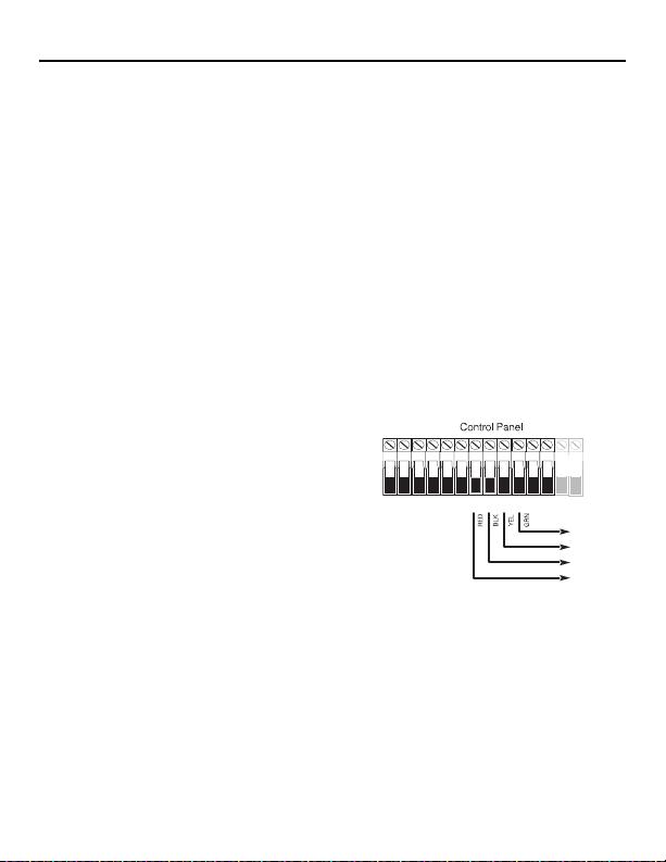
2.3 Connect the TR5164 Receiver
CAUTION: Remove all power (AC, DC, telephone lines)
from the system while connecting modules to the Keybus.
Connect the TR5164 to the four-wire Keybus of the
ol panel according to Figure 1.
contr
Once the wiring is complete, r
security system.
Next, enroll and program the wireless devices. See
Section 3.1, page 6 for instructions.
2.4 Receiver Placement Test
The TR5164 performs best in locations where RF interference is minimal. To find the best mounting
location, perform the following placement test:
1. Apply power to the TR5164 and hold it in the intended mounting location.
2. If the yellow Trouble LED is on, interference levels ar
be found. If the LED is flashing or off, interference is low and the location is good.
f all wireless devices
including: electrical noise (computers, televisions, electric
educed if mounted below ground level.
f the unit
econnect power to the
AC AC + AUX - + BELL -
RED BLK YEL GRN
Figure 1
e high and a new mounting location should
PC1864
Only
1 PGM 2 3 PGM 4
KEYBUS
TO TR5164
5

Section 3: Receiver Programming
Enrollment consists of programming the device’s Electronic Serial Number (ESN) into the TR5164 so it
can be identified when an event is communicated. The ESN is located on the back of each device.
This section describes how to enroll and program:
• wireless devices using zones
• wireless keys
For more information, read the instruction sheet
3.1 Enroll the Wireless Keypad On The TR5164
During initial power-up of the alarm panel, a 2-minute window is established for enrolling the wireless
keypad (indicated by flashing red and green LEDs). If the enrollment window expires, power down the
panel then power it up again. By default, WT5500 keypads are automatically assigned to slot numbers
8, 7, 6, 5.
To enroll a keypad:
1. Power up the alarm system.
2. Power up the keypad. After a few secon
3. Press the [1] and [
If the “Failed to Enroll” message is displayed, perform the following:
• Retry the enrollment.
• Reposition the keypad closer to the control panel.
• Verify that the red and green indicators are flashing on the TR5164. I
AC and DC power sources then reconnect.
• Check for RF interference. If the yellow LED is lit, RF traffic or noise floor level is too high.
NOTE: Set the zone definitions for wireless keypad slots as type 26 - 24Hr Non-Alarm.
3.2 Quick Enroll Wireless Devices/Keypads (WT5500 only)
1. Enter [,][8][Installer Code][898]. “Wireless Enrollment Mode” is displayed.
2. Activate the device as indicated below.
• Keypad: Press the [
• Wireless key: Press any key to activate.
• Detectors (PIR, Smoke, Glass break): Press the Tamper button.
• Repeater: Press the Tamper button. Note: Ensure that dip switch 3 on the repeater is in the off
position
3. The Electronic Serial Number (ESN)
the ESN is incorrect, press [#] then repeat step 2.
4. After successful confirmation of the ESN, t
• The next open slot for the device type is displayed. Press [,] to accept or key in another slot.
• To re-enroll a wireless key on another system, press
3.3 Change Keypad Slot Assignment
To change the default slot number for a WT5500 keypad:
1. Enter Installer Programming [
2. Enter section [804][000]. A 2-dig
3. In the first field, enter 1 for Partition 1 (only Partition 1 is supported). In the second field, enter a
keypad slot number from 1-8 (e.g., 1,8 represents Partition 1, keypad slot 8).
4. Record the assigned slot number in the programmi
,] keys together to enroll. “WFKP Enrollment Successful” is displayed.
,] and [1] keys at the same time.
before quick enrolling a repeater.
,][8][installer code].
included with each device.
ds, “Hold [1] and [,] to Enroll Keypad” is displayed.
f not, disconnect the panel from
is displayed on the keypad. Press [,] to confirm the ESN. If
he system prompts for the zone/slot number.
together for 3 seconds.
it field is displayed.
ng worksheets at the back of this manual.
6

5. After re-assigning a keypad, perform a supervisory reset by entering[,][8][Installer Code][902]
and wait for 60 seconds.
6. Press [#] twice to exit after 60 seconds.
3.4 Manually Enroll Wireless Devices/Keypads
To manually enroll a 2-way wireless device:
1. Enter [,][8][Installer Code][804].
2. Enter the 3-digit zone/slot corr
Wireless sensors, pendants, repeaters [804][001]-[064] (excluding [029]-[032])
Wireless Key [804][101]-[116] for wireless key numbers 01- 16
Wireless Keypad [804][029]-[032]
NOTE: Hardwired and wireless devices cannot be assigned to the same zone. PC5108 zone
expander modules occupy zones in 2 groups of 4 (e.g., zones 9-12 and zones 13-16). None of
the zones assigned to a PC5108 module may be used for wireless devices. For more
information on zone assignment, consult the system installation manual.
A wireless key can only be assigned to one par
different partition, see “[804][183] Wireless Key (1-16) Partition Assignments” on page 20.
3. Enter the device serial number. On PK keypads, this is
ESN, do not program the first two digits. On WT keypads, this is an 8-digit entry. When
programming a 6-digit ESN, enter 00 for the first two digits. To toggle between decimal and
hexadecimal values, press [
system installation manual. The device is now enrolled on the system.
4. Record the serial number and the assigned
back of this manual.
5. Continue with steps 2 - 4 until all wireless devices are enrolled.
6. Press [#] to exit.
NOTE: Zone and partition programming must be completed for the wireless devices to
operate correctly (see Section 4.1, page 8).
NOTE: (For non-UL listed installations) For Repeaters and Wireless Keypads, non-alarm
zone type 26 is recommended. With this zone type, loss of AC or a Low battery condition are
not reported to the central station. The alarm panel does not show a trouble for the zone but
will indicate it as open. Select the Force Arm attribute for this zone. Program a zone label to
identify the WS4920 or WT5500. E.g., "Rptr 1 Pwr Trbl."
NOTE: (For UL listed installations) If AC loss and low battery must be reported to the
central station, use a 24-hour zone type. Ensure the Audible attribute is set to Silent.
To delete a wireless device:
1. At a system keypad, enter [
2. Enter the 3-digit number corresponding to the zone
3. Program the ESN as [00000000]. The device is deleted.
4. Press [#] to exit.
Once all wireless devices are enrolled, program the system to work with the devices. See 4.1
“Program Zones and Partitions” on page 8 for more information.
esponding to the device type:
tition (partition 1 by default). To assign keys to a
a 6-digit entry. When entering an 8-digit
,]. For instructions on programming hexadecimal numbers, see the
zone number in the programming worksheets at the
,][8][Installer code][804].
you want to remove the device from.
7

Section 4: Other Programming
4.1 Program Zones and Partitions
Once all wireless devices are enrolled, complete zone programming on the system. Ensure that the
following programming options are completed correctly for each wireless zone:
• Enable zones and/or assign zones to one or more partitions (programming sections [202] to [265]).
• Program the definition for each zone (programming sections [001]-[004]).
• Enable the wireless zone attribute for each wireless zone (sections [101]-[164]).
Refer to the system installation manual for more information on the above programming sections.
4.2 Enable TR5164 Supervision
The control panel can supervise the TR5164 receiver via the Keybus after at least one device has been
enrolled on the module (Section 3.1, page 6).
To activate module supervision:
1. Enroll the first device(s).
2. Exit and then re-enter Installer Programming, [,][8].
3. Enter programming section [902]. Wait approximately 60 seconds while the system scans for
connected modules.
4. To exit press [#].
The system generates a General System Supervisory trouble if the module is removed from the
Keybus. If the TR5164 module must be removed from an existing system, first disable TR5164
supervision.
NOTE: Deleting all devices from the TR5164 or defaulting the TR5164 causes a supervisory
fault.
To disable TR5164 supervision:
1. Disconnect the TR5164 from the Keybus.
2. Enter [,][8][Installer Code].
3. Enter [902]. The control panel clears all supervision and re-scans the system for connected
modules. The scan takes approximately 60 seconds.
4. To exit press [#].
To verify control panel supervision of the TR5164 (not available on WT5000 keypads):
1. Enter [,][8][Installer Code].
2. Enter [903] to display all modules. On an LED 32 zone keypad, light [17] indicates that the TR5164
is present on the system. On LCD keypads, scroll until the TR5164 module name is displayed.
3. To exit press [#].
If the TR5164 is not detected, check for one of the following problems:
• The module is not connected properly to the Keybus
• The Keybus wiring run is faulty
• The module does not have enough power
• No devices have been enrolled on the TR5164
Interference
An RF Jam happens when an unwanted transmission from an outside source occurs in the receiver's
area of operation that impedes the function of one or more devices.
The receiver is able to detect an RF jam condition and indicate an appropriate trouble to the control
panel. This feature may be disabled in section [804][900], option [7].
8

4.3 Enable Supervision of Wireless Zones
Each wireless device (excluding wireless keys) sends a supervisory signal periodically. If the receiver
does not receive a signal within the time programmed for the Wireless Supervisory Window, it
generates a supervisory fault.
NOTE: For wireless supervision to work, enable the wireless zone attribute on all wireless zones
(sections [101] to [164], option [8] ON).
To program the wireless supervisory window:
1. Enter [,][8][Installer Code] to access Installer Programming.
2. Enter [804] to access TR5164 Module Programming.
3. Enter section [081].
4. Enter the time period for the supervisory window. The window is programmed in 15 minute
increments. The default programming is:
• 96 (x15minutes), which is equal to 24 hours for the NA version, or
• 8 (x15minutes), which is equal to 2 hours for the EU version.
Valid entries are (4) to (96), equal to 1 to 24 hours.
5. To exit press [#].
NOTE: Supervision must be enabled for RF Delinquency.
To disable/enable zone supervision:
1. Enter [,][8][Installer Code] to access Installer Programming.
2. Enter [804] to access TR5164 Module Programming.
3. Enter sections [082]-[089]. Enable or disable supervision for each wireless zone by turning each
relevant option on or off. Supervision is enabled by default for all wireless zones.
4. To exit press [#].
4.4 Reporting Openings/Closings by Wireless Keys
Openings, closings and command output activation (e.g., opening a garage door) by individual
wireless keys can generate a system report on certain control panels.
To enable reporting for wireless key openings/closings:
1. Program a valid access code for each key (using [,][5] access code programming).
NOTE: Program these access codes on the system after the TR5164 is connected to the
Keybus (
Section 2.4, page 5). Access codes 17 – 32 are reserved for wireless keys 01-16
respectively. Refer to the alarm panel installation manual for information on access code
programming.
2. Program an opening and closing reporting code for each key ([339]-[340], [342]-[343]).
3. Turn off the Quick Arm option in section [015] option [4] of Installer Programming.
NOTE: To ensure that an unidentified wireless key cannot disarm the system, turn off
section [017], option [1] in Installer Programming.
9

4.5 Program Wireless Key Function Buttons
Wireless keys have four or six programmable function buttons. Default functions have been assigned,
but other functions may be programmed if desired.
NOTE: 2-way wireless keys (WT4989) can only be assigned to partition 1.Wireless keys do not
work when the partition is being programmed or bypassed.
To program wireless key function buttons:
1. At a system keypad, enter [,][8][Installer Code].
2. Enter programming section [804].
3. Enter programming section [141] to [156] for wireless keys 1-16.
4. For each of the available buttons on the wireless key, enter the 2-digit number corresponding to the
selected function. See
options.
5. Record all programming choices in the worksheets in the back of the manual.
6. To exit press [#].
For more information on programming wireless key function buttons, refer to the wireless key
installation sheet.
“Wireless Key Function Key Options” on page 18 for a list of function key
4.6 TR5164 Software Default
Returning the TR5164 programming to factory default settings removes all enrolled devices from the
system and resets programming in section [804].
NOTE: Performing this procedure does not reset any other programming sections on the control
panel. Likewise, resetting the control panel to factory defaults does not effect TR5164
programming.
To reset TR5164 programming to factory default settings:
1. Enter [,][8] [Installer Code].
2. Enter programming section [996].
3. Enter the Installer Code, followed by [996] again. The software for the TR5164 is reset to factory
defaults.
4. To continue programming the unit, exit and then re-enter Installer Programming by pressing [#]
[,][8] [Installer Code].
For instructions on resetting the control panel or any other connected module to factory defaults, see the
control panel installation manual.
10

Section 5: Testing & Mounting
5.1 Test the Reception of Wireless Devices
Testing the proposed placement of each wireless device before it is mounted is very important.
Following these steps tests the signal strength between the TR5164 and the wireless devices.
All wireless devices can be tested
NOTE: After the wireless devices are enrolled, Installer Programming must be exited and then
re-entered at least once before performing a placement test.
To perform a global placement test:
1. Temporarily place the wireless devices in th
2. At a system keypad, enter [,][8][Installer Code].
3. For WT5500 keypads, enter section [904] then key in [
placement tested at the same time.
4. For PK keypads, set section [804][900] option 8 to ON.
number of any wireless device.
5. Activate the device(s) as described in th
keypads, press any key except the # key. The device name and zone number are displayed on the
LCD.
Read the test results at the keypad:
Result LED Keypad LCD Keypad Buzzer/Bell
Good Light 1 On Steady “Good” 1 Beep/Squawk
Bad Light 3 On Steady “Bad” 3 Beeps/Squawks
6. Activate the device until three “good” r
7. Mount the wireless devices where results are good. Devices indicating a bad result must be moved
to another location. The device may only have to be moved a few inches to correct a bad result.
Do not mount any device where a “bad” test result is indicated.
8. Perform step 4 for each wireless device enrolled on
Wait until the placement test of one device is shown/sounded before testing the next one.
Continue to test the devices until both the TR5164 and the devices are in good locations. If several
wireless devices prod
(see Section 2.2, page 5 for tips on finding a suitable location).
9. To exit the placement test and return to Installer Programming, press [#] twice.
Testing Individual Devices
1. Temporarily place the device in the pr
2. At a system keypad, enter [
3. Enter programming section [904] for wireless devices.
[804][900] option 8 is OFF.
4. Enter the 2-digit zone number f
5. Activate the device until a result is displayed
6. To test another device, press [#] once, then repeat steps 4 - 5. Continue to test the devices until
both the TR5164 and the devices are in acceptable locations.
If several wireless devices produce “b
location (see Section 2.2, page 5 for tips on finding a location for the TR5164).
7. To exit the placement test and Installer
together (global placement testing) or individually.
e preferred mounting locations.
00]. In this mode, all wireless devices are
Enter section [904] then key in the zone
e associated installation sheet. For two-way wireless
esults in a row are achieved.
the TR5164.
uce “bad” test results, consider moving the TR5164 to a different location
eferred mounting location.
,][8][Installer Code].
or the device.
ad” test results, consider moving the TR5164 to a better
Programming, press [#] twice.
For PK keypads, ensure section
on the keypad or sounded by the keypad or bell.
11

Testing Individual Wireless Keys
Do not use the individual device test d
receiving transmissions from these devices, use the function keys on the wireless keys at several
different points throughout the installation.
NOTE: Two-way wireless keys must be activated by pressing any key before they become
functional.
5.2 Mounting
Once reception between the TR5164 and all wireless devices has been tested and verified (Section 5.1,
page 11), mount as follows:
TR5164
1. Pull the Keybus wires through the holes at the back of the cabinet or through the breakaway tabs at
the sides.
2. Mount the cabinet securely to the wall using
escribed above to test wireless keys. To ensure that the TR5164 is
the supplied 2 (two) screws. See Figure 2.
Breakaway
Tab
Breakaway
Tab
Figure 2
Wireless Devices
Mount the wireless devices once the placement test described in section 5.1 has been successfully
completed and three “good” results in a row have been achieved for each device. See the installation
sheet for each device for mounting instructions.
Now that the TR5164 and wireless devices are mounted and wor
13, for information on potential wireless trouble
conditions and battery replacement.
king properly, read Section 6.1, page
12

Section 6: Additional Notes
6.1 Trouble Conditions
The control panel constantly monitors for possible trouble conditions. If a trouble condition is
detected, the keypad beeps and the “Trouble” light turns on. Press [
The following trouble conditions apply to the TR5164 and/or any enrolled devices.
• RF Jam Detected (on Power panels v.2.01 and below) - This trouble is generated when the
TR5164 detects an RF Jamming condition.
• Module Supervision- This trouble is generated if the panel loses communication with any module
connected to the Keybus. The event buffer logs a detailed description of the event.
• Wireless Device Low Battery - This trouble is generated when a wireless device exhibits a low
battery condition. Press [7] one, two, or three times to view which devices are experiencing battery
failure. An LED keypad indicates battery failure using zone lights 1 to 8. See
for more information.
• Zone Tamper - This trouble is generated when an enrolled wireless device is removed from its
mounting location.
• Zone Fault - Each wireless device sends a supervisory signal every 64 minutes (15 minutes for
EU). If the receiver does not receive a signal within the time programmed for the Wireless
Supervisory Window, a zone fault is generated.
• RF Delinquency (EU only) - Each wireless zone sends a supervisory signal every 15 minutes. If
the receiver does not receive a signal within 15 minutes, an RF Delinquency trouble is generated
for that zone.
NOTE: WT5500 keypad and wireless repeater AC and low battery troubles cause the
corresponding zone to show as open on the alarm panel.
6.2 Wireless Zone Low Battery Transmission
The battery status of each device is regularly communicated to the alarm panel. If a battery is low, the
system logs a Device Low Battery trouble.
The system delays reporting the event to the central station for the number of days programmed for
Zone Low Battery Transmission Delay in section [377] of the panel. This prevents unnecessary
reporting of the event if the user has been instructed on how to replace batteries.
Replacing Batteries in Wireless Devices
1. Refer to the battery installation instructions on the installation sheet of each device. Be sure to
observe correct polarity when installing new batteries.
2. When the new batteries are in place and the tamper is restored, the battery trouble is cleared and
the device should function normally.
,][2] to display trouble conditions.
Section 6.2, page 13
13

Section 7: Troubleshooting
1. When I enter the 3-digit zone number for adding a wireless device, the keypad gives me a
long beep.
ESNs can be entered only when a TR5164 wireless receiver is connected to the Keybus. See
2.3, page 5
for instructions on setting up and wiring the TR5164 module.
2. I have entered the ESN for the device but when I activate it, the zone does not show open on
the keypad.
Check the following:
• Ensure the ESN has been entered correctly.
• Ensure that the zone is enabled for the partition (if partition programming is used).
• Ensure that the wireless zone is not assigned to a zone used by PC5108 modules, an on-board
zone, or a keypad zone.
• Ensure that the zone is programmed for something other than “Null Operation,” and that the
Wireless Zone attribute is turned on.
3. When I try a module placement test I get no result or “bad” results.
Check the following (see Section 5.1, page 11 for more information on testing devices):
• Verify that the correct zone is being tested.
• Verify that the correct ESN was entered when the device was enrolled.
• Verify that the device is in range of the TR5164. Try testing the device in the same room as the
receiver.
• Confirm that the TR5164 is properly connected to the Keybus (see Section 2.4, page 5 for
TR5164 set up and wiring instructions).
• Check that the zone is being tested correctly (see Section 5.1, page 11 for testing instructions).
• Check that the batteries are working and installed correctly.
• Look for large metal objects that may be preventing the signal from reaching the TR5164.
The device must be located where consistent “good” results are obtained. If several devices show
“bad” results, move the receiver. See Section 2.2, page 5 for tips on choosing a mounting location
for the TR5164.
4. The LED on the motion detector does not turn on when I walk in front of the unit.
The LED is for walk test purposes only. See the Wireless PIR Instruction Sheet for walk test
instructions.
Section
14
Section 8: Programming Worksheets
TR5164 Wireless Programming
Use the following worksheets to record wireless device pr
NA= default value for North America; EU= default value for Europe
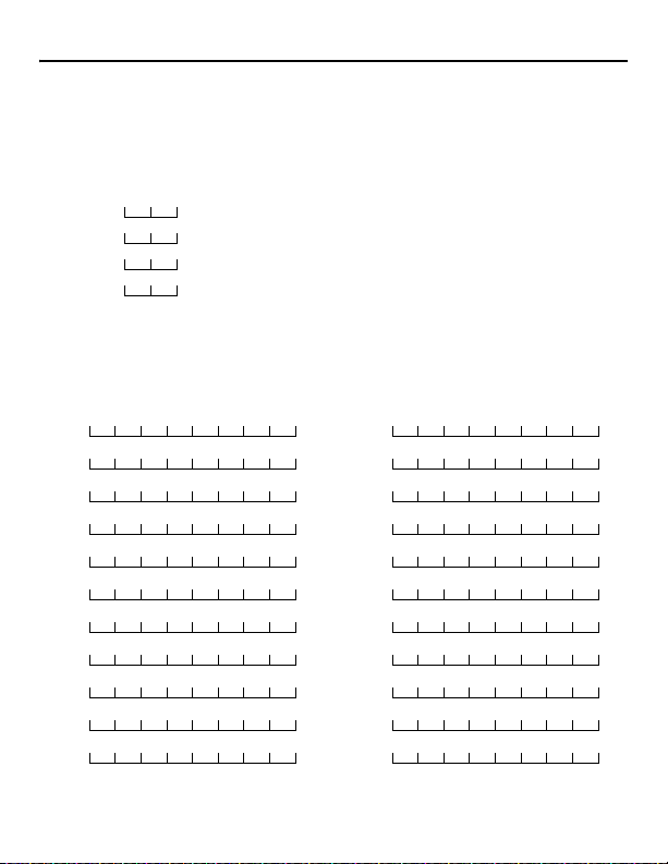
[804][000] Wireless Keypad Partition and Slot Programming
Keypad Default
WT5500 #1 1,8
WT5500 #2 1,7
WT5500 #3 1,6
WT5500 #4 1,5
[804][001]-[064] Wireless Zone Programming
Wireless keypads 1-4 must be enrolled into zones 29-32 respectively. All other wireless devices may be enrolled into any of the remaining 60 zones.
Default = 00000000
NOTE:
1 is supported). The second digit is the keypad slot number.
(e.g., 1,8 = partition 1, slot 8) Wireless keypads can be
programmed into slots 1-8. Default slots are 8,7,6,5.
Zone Zone
[001] [012]
[002] [013]
[003] [014]
[004] [015]
[005] [016]
[006] [017]
[007] [018]
[008] [019]
[009] [020]
[010] [021]
[011] [022]
ogramming options for future reference.
The first digit represents the partition (only partition
(for wireless devices, repeaters and keypads)
15
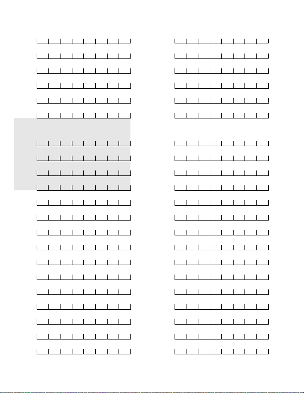
Zone Zone
[023] [044]
[024] [045]
[025] [046]
[026] [047]
[027] [048]
[028] [049]
Wireless Keypad 1-4
[029] [050]
[030] [051]
[031] [052]
[032] [053]
[033] [054]
[034] [055]
[035] [056]
[036] [057]
[037] [058]
[038] [059]
[039] [060]
[040] [061]
[041] [062]
[042] [063]
[043] [064]
16

[804][081] Wireless Supervisory Window (Default = 96)
The window is programmed in 15 minute increments.
The default programming is:
• 96 (x15minutes), which is equal to 24 hours (NA), or
• 8 (x15minutes), which is equal to 2 hours (EU).
Valid entries are (004) to (
NOTE:
[804][082]-[089] Zone Transmitter Supervision
[082] Zone 1-8 [083] Zones
Opt Def. Def. Def. Def.
1 Zone 1 Zone 9 Zone 17 Zone 25
2 Zone 2 Zone 10 Zone 18 Zone 26
3 Zone 3 Zone 11 Zone 19 Zone 27
4 Zone 4 Zone 12 Zone 20 Zone 28
5 Zone 5 Zone 13 Zone 21 Zone 29
6 Zone 6 Zone 14 Zone 22 Zone 30
7 Zone 7 Zone 15 Zone 23 Zone 31
8 Zone 8 Zone 16 Zone 24 Zone 32
[086] Zone
Opt Def. Def. Def. Def.
1 Zone 33 Zone 41 Zone 49 Zone 57
2 Zone 34 Zone 42 Zone 50 Zone 58
3 Zone 35 Zone 43 Zone 51 Zone 59
4 Zone 36 Zone 44 Zone 52 Zone 60
5 Zone 37 Zone 45 Zone 53 Zone 61
6 Zone 38 Zone 46 Zone 54 Zone 62
7 Zone 39 Zone 47 Zone 55 Zone 63
8 Zone 40 Zone 48 Zone 56 Zone 64
NOTE: Panic transmitters are NOT supervised and must be disabled in this section.
33-40
[087] Zones
096), equal to 1 to 24 hours.
Options
[084] Zones
9-16
41-48
17-24
[088] Zones
49-56
[085] Zones
25-32
[089] Zones
57-64
17
[804][101]-[116] Wireless Key Serial Numbers
[101] [109]
[102] [110]
[103] [111]
[104] [112]
[105] [113]
[106] [114]
[107] [115]
[108] [116]
Wireless Key Function Key Options
Entry Key Description Entry Key Description
00 Null Key 18 Global Away Arm
01-02 Future Use 19 [,][7][3] Command Output #3
03 Stay Arm 20 Future Use
04 Away A rm 21 [,][7][4] Command Output #4
05 [,][9] No-Entry Arm 22 Global Disarm
06 [,][4] Chime ON/OFF 23-26 Future Use
7-12 Future Use 27 Disarm (OFF)
13 [,][7][1] Command Output #1 28 Future Use
14 [,][7][2] Command Output #2 29 Auxiliary Alarm
15 Global Stay Arm 30 Panic Alarm
16 [,][0] Quick Exit 31-33 Future Use
17 [,][1] Activate Stay/Away
Wireless keys must have an access code for glo
NOTE:
bal arm/global disarm functions.
18
[804][141]-[156] Wireless Function Key Options
Function 1 Function 2 Function 3 Function 4 Function 5 Function 6
Default 0,3 Default 0,4 Default 2,7 Default 3,0 Default 1,3 Default 1,4
[141] Key 1
[142] Key 2
[143] Key 3
[144] Key 4
[145] Key 5
[146] Key 6
[147] Key 7
[148] Key 8
[149] Key 9
[150] Key 10
[151] Key 11
[152] Key 12
[153] Key 13
[154] Key 14
[155] Key 15
[156] Key 16
NOTE: Functions 5 and 6 are for WT4989 only.
19
[804][181]-[182] Enable/Disable 2-Way Wireless Keys 1-16
[804][181] Enable/Disable 2-Way
s Keys 1-8
Wireles
Opt Def ON OFF Opt Def ON OFF
[804][182] Enable/Disable 2-Way Wireless
Keys 9-16
1 Off Key 1 is 2-way Key 1 is 1-way 1 Off Key 9 is 2-way Key 9 is 1-way
2 Off Key 2 is 2-way Key 2 is 1-way 2 Off Key 10 is 2-way Key 10 is 1-way
3 Off Key 3 is 2-way Key 3 is 1-way 3 Off Key 11 is 2-way Key 11 is 1-way
4 Off Key 4 is 2-way Key 4 is 1-way 4 Off Key 12 is 2-way Key 12 is 1-way
5 Off Key 5 is 2-way Key 5 is 1-way 5 Off Key 13 is 2-way Key 13 is 1-way
6 Off Key 6 is 2-way Key 6 is 1-way 6 Off Key 14 is 2-way Key 14 is 1-way
7 Off Key 7 is 2-way Key 7 is 1-way 7 Off Key 15 is 2-way Key 15 is 1-way
8 Off Key 8 is 2-way Key 8 is 1-way 8 Off Key 16 is 2-way Key 16 is 1-way
[804][183] Wireless Key (1-16) Partition Assignments
(Default = 01)
Key 1 Key 9
Key 2 Key 10
Key 3 Key 11
Key 4 Key 12
Key 5 Key 13
Key 6 Key 14
Key 7 Key 15
Key 8 Key 16
[804][800] Keypad Miscellaneous Options
Option Default Option ON Option OFF
1 On Chime on Openings Enabled
2 Off
3-8 Off
Chime on Closings Enabled
Future Use
Chime on Openings Disabled
Chime on Closings Disabled
20
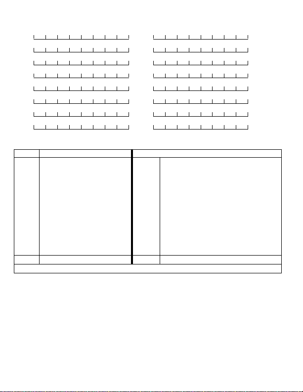
[804][801] - [864] Custom Door Chime Programming
Opt Default Description
1 On 6 Beeps
2 Off “Bing-Bing” sound
3 Off “Ding-Dong” sound
4 Off Alarm Tone
5-8 Off Future Use
[801] [815] [829] [843] [857]
[802] [816] [830] [844] [858]
[803] [817] [831] [845] [859]
[804] [818] [832] [846] [860]
[805] [819] [833] [847] [861]
[806] [820]
[807] [821] [835] [849] [863]
[808] [822] [836] [850] [864]
[809] [823] [837] [851]
[810] [824] [838] [852]
[811] [825] [839] [853]
[812] [826] [840] [854]
[813] [827] [841] [855]
[814] [828] [842] [856]
1 2 3 4 1 2 3 4 1 2 3 4 1 2 3 4 1 2 3 4
1 2 3 4 1 2 3 4 1 2 3 4 1 2 3 4 1 2 3 4
1 2 3 4 1 2 3 4 1 2 3 4 1 2 3 4 1 2 3 4
1 2 3 4 1 2 3 4 1 2 3 4 1 2 3 4 1 2 3 4
1 2 3 4 1 2 3 4 1 2 3 4 1 2 3 4 1 2 3 4
1 2 3 4 1 2 3 4 1 2 3 4 1 2 3 4 1 2 3 4
1 2 3 4 1 2 3 4 1 2 3 4 1 2 3 4 1 2 3 4
1 2 3 4 1 2 3 4 1 2 3 4 1 2 3 4 1 2 3 4
1 2 3 4 1 2 3 4 1 2 3 4 1 2 3 4
1 2 3 4 1 2 3 4 1 2 3 4 1 2 3 4
1 2 3 4 1 2 3 4 1 2 3 4 1 2 3 4
1 2 3 4 1 2 3 4 1 2 3 4 1 2 3 4
1 2 3 4 1 2 3 4 1 2 3 4 1 2 3 4
1 2 3 4 1 2 3 4 1 2 3 4 1 2 3 4
`
[834] [848] [862]
(for zones 1-64)
21

[804][900] General Wireless Options
Option Default Option ON Option OFF
NA EU
1-2 Off Off Future Use Future Use
3 On Off Wall Tamper Disabled Wall Tamper Enabled
4 Off Off Case Tamper Disabled Case Tamper Enabled
5 On Off Wireless Delinquency Disabled Wireless Delinquency Enabled
6 Off Off Future Use Future Use
7 On Off RF Jam Disabled RF Jam Enabled
8 Off Off
Global Placement Test (PK keypads only)
Individual Placement Test
NOTE: For UL Listed installations, the RF Jam feature must be enabled - [804][900] option 7 OFF.
[904] Wireless Device Placement Test
8.1 See “Testing Individual Devices” on page 11 for details.
[996] Restore Labels to Factory Default
Entering this section and pressing [
currently active language. Keypad configuration sections are not affected.
Limited Warranty
Digital Security Controls warrants the original purc haser that for a period of twelve months from the date of purchase, the pro duct shall be free of defects in materials and workmanship under normal use. During the warranty period, Digital Security Controls shall, at its option, repair or replace any defecti
charge for labour and materials. Any replacement and/or repaired parts are warranted for the remainder of the original warranty or ninety (90) days, whichever is longer. The original
purchaser must promptly notify Digital Security Controls in writing that there is defect in material or workmanship, such written notice to be received in all events prior to expiration
of the warranty period. There is absolutely no warranty on software and all software products are sold as a user license under the terms of the software license agreement included
with the product. The Customer assumes all responsibility for the proper selection, installation, operation and maintenance of any products purchased from DSC. Custom products
are only warranted to the extent that they do not function upon delivery. In such cases, DSC can replace or credit at its option.
International Warranty
The warranty for international customers is the same as for any cust
sible for any customs fees, taxes, or VAT that may be due.
Warranty Procedure
To obtain service under this warranty, please return the items) in question to the point of purchase. All authorized distributors
goods to Digital Security Controls must first obtain an authorization number. Digital Security Controls will not accept any shipment whatsoever for which prior authorization has not
been obtained.
Conditions to Void Warranty
This warranty applies only to defects in parts and workm
• damage incurred in shipping or handling;
• damage caused by disaster such as fire, flood, wind, earthquake or lightning;
• damage due to causes beyond the control of D
• damage caused by unauthorized attachment, alterations, modifications or foreign objects;
• damage caused by peripherals (unless such peripherals were supplied by Digital Security Controls);
• defects caused by failure to provide a suitable installation environment for the products;
• damage caused by use of the products for purposes other than those for which it was designed;
• damage from improper maintenance;
• damage arising out of any other abuse, mishandling or improper application of the products.
Items Not Covered by Warranty
In addition to the items which void the Warranty, the following items shall not be covered by Warranty: (i) freight cost to the repai
DSC's product label and lot number or serial number; (iii) products disassembled or repaired in such a manner as to adversely affect performance or prevent adequate inspection or
testing to verify any warranty claim. Access cards or tags returned for replacement under warranty will be credited or replaced at DSC's option. Products not covered by this warranty, or otherwise out of warranty due to age, misuse, or damage shal l be evaluated, and a repair estimate shall be provided. N
order is received from the Customer and a Return Merchandise Authorisation number (RMA) is issued by DSC's Customer Service.
Digital Security Controls’s liability for fail
exclusive remedy for breach of warranty. Under no circumstances shall Digital Security Controls be liable for any special, incidental, or consequential damages based upon breach
of warranty, breach of contract, negligence, strict liability, or any other legal theory. Such damages include, but are not limited to, loss of profits, loss of the product or any associated
equipment, cost of capital, cost of substitute or replacement equipm ent, facilities or services, down time, purchaser’s time, the claims of third parties, including customers, and injury
to property. The laws of some jurisdictions limit or do not allow the disclaimer of consequential damages. If the laws of such a jurisdiction apply to any claim by or against DSC, the
limitations and disclaimers contained here shall be to the greatest extent permitted by law. Some states do not allow the exclusion or limitation of incidental or consequential damages, so that the above may not apply to you.
Disclaimer of Warranties
This warranty contains the entire warranty and shall be in lieu of
fitness for a particular purpose) and of all other obligati ons or liabilities on the part of Digital Security Controls. Digital Security Controls neither assum es responsibility for nor
authorizes any other person purporting to act on its behalf to modify or to change this warranty, nor to assume for it any other warranty or liability concerning this product.
This disclaimer of warranties and limited warranty are governe
WARNING: Digital Security Controls recommends that the entire system be completely tested on a regular basis. However, despite frequent testing, and due to, but not limited to,
criminal tampering or electrical disruption, it is possible for this product to fail to perform as expected.
Out of Warranty Repairs
Digital Security Controls will at its option repair or replace out-of-warranty products which are returned to its factory according to the following conditions. An yone returning goods to Digital
Security Controls must first obtain an aut horization number. Digital Security Controls will not accept any shipm ent whatsoever for which prior authorization has not been obtained.
Products which Digital Security Controls determines to be repairable will be repaired and returned. A set fee which Digital Security Controls has predetermined and which may be
revised from time to time, will be charged for each unit repaired.
,] returns all programmable system labels to their default settings in the
ve product upon return of the product to its factory, at no
omer within Canada and the United States, with the exception that Digital Security Con trols shall not be respon-
and dealers have a warranty program. Anyone returning
anship relating to normal use. It does not cover:
igital Security Controls such as excessive voltage, mechanical shock or water damage;
r centre; (ii) products which are not identified with
ure to repair the product under this warranty after a reasonable number of attempts will be limited to a rep lacement of the product, as the
any and all other warranties, whether expressed or implied (including all implied warranties of merchantability or
d by the laws of the province of Ontario, Canada.
o repair work will be performed until a valid purchas e
22

Avertissement : À lire attentivement
Note pour les installateurs
Cet avertissement contient des informations vitales. Puisque vous êtes la seule personne en contact avec les utilisateurs du système, il vous revient d’attirer l’attention
des usagers du système sur chacun des articles de cet avertissement.
Pannes du système
Ce système a été soigneusement conçu pour être aussi efficace que possible. Toutefois, dans certaines circonstances d’incendie, d’intrusion ou autres types d’urgence
il se peut qu’il n’offre pas de protection. Tout système d’alarme, quel qu’il soit peut
être compromis délibérément ou peut ne pas fonctionner normalement pour
diverses raisons. Ces raisons peuvent être notamment, mais pas exclusivement
• Mauvaise installation
Un système de sécurité doit être installé correctement pour offrir une protection
adéquate. Chaque installation devrait être évaluée par un professionnel de la sécurité afin de s’assurer que tous les points d’accès et zones sont couverts. Les serrures
et verrous sur les portes et fenêtres doivent être sûrs et fonctionner correctement.
Les fenêtres, portes, murs plafonds et autres matériels de construction doivent être
assez solides et bien construits pour offrir le niveau de protection attendu. Une réé
valuation doit être faite durant et après toute activité de construction. Une évaluation des pompiers ou de la police est vivement recommandée si ce service est
offert.
• Connaissances criminelles
Ce système comporte des caractéristiques de sécurité qui, au moment de sa fabrication, étaient considérées comme étant efficaces. Il est possible pour des personnes
ayant des intentions criminelles d’élaborer des techniques qui réduisent l’efficacité
de ces caractéristiques. Il est important qu’un système de sécurité soit examiné
périodiquement pour s’assurer que ses caractéristiques restent efficaces et pour
l’actualiser ou le remplacer s’il n’offre plus la protection attendue.
•Intrusion
Des intrus peuvent entrer par des endroits non protégés, contourner un détecteur,
éluder la détection en passant par une zone qui n’est pas bien couverte, en débran
chant un dispositif avertisseur, ou en brouillant ou empêchant le bon fonctionnement du système.
• Panne de courant
Les dispositifs de contrôle, détecteurs d’intrusion, détecteurs de fumée et de nombreux autres dispositifs de sécurité ont besoin d’une alimentation appropriée pour
un bon fonctionnement. Si un dispositif fonctionne sur des piles, il est possible
qu’elles soient défaillantes. Même si les pi les ne sont pas défaillantes, elles doivent
être chargées, en bonne condition et installées correctement. Si un dispositif ne
fonctionne que sur le secteur, toute interruption, aussi courte soit-elle, rendra le dis
positif inopérant tant qu’il n’est pas alimenté. Des coupures de courant pendant un
temps quelconque sont souvent accompagnées de fluctuations de tension qui
peuvent endommager les appareils électroniques tels qu’un système de sécurité.
Après une coupure de courant, effectuez immédiatement un essai complet du sys
tème afin de vous assurer que le système fonctionne correctement.
• Panne de piles remplaçables
Les émetteurs sans fil de ce système ont été conçus pour donner plusieurs années
de vie de la pile dans des conditions normales. La durée de vie prévue pour la pile
dépend de l’environnement, de l’usage et du type du dispositif. Les conditions
ambiantes telles qu’une humidité élevée, des températures basses ou élevées ou
d’importants changements de température peuvent réduire la durée de vie prévue
de la pile. Bien que chaque dispositif de trans mission ait un contrôle pour pile
faible qui détermine quand les piles doivent être remplacées, ce contrôle pourrait
ne pas fonctionner correctement. Des essais et un entretien réguliers assureront un
bon fonctionnement du système.
• Brouillage de la radio fréquence des dispositifs (sans fil)
Les communications peuvent ne pas toujours arriver au récepteur, à cause par
exemple d’objets métalliques placés sur la trajectoire du signal, d’un brouillage
délibéré ou d’autres brouillages du sign al radio par inadvertance.
• Utilisateurs du système
Il se peut qu’un utilisateur ne soit pas en mesure d’appuyer sur le bouton de
panique ou d’urgence à cause d’une incapacité physique permanente ou tempo
raire, de l’impossibilité d’atteindre le dispositif à temps ou de l’ignorance du bon
fonctionnement du dispositif. Tous les utilisateurs du système doivent recevoir une
formation relativement au bon fonctionnement du système d’alarme et ils devraient
tous savoir comment réagir lorsque le système indique une alarme.
• Détecteur de fumée
Les détecteurs de fumée qui font partie de ce système peuvent ne pas alerter les
occupants d’un incendie pour plusieurs raisons, notamment, mais pas exclusivement. Les détecteurs de fumée ont été mal installés ou mal placés. La fumée peut
ne pas accéder aux détecteurs de fumée, comme dans les cas d’incendie de chem i
née, d’incendie à l’intérieur d’un mur, sur le toit ou de l’autre côté d’une porte fermée. Les détecteurs de fumée peuvent ne pas détecter la fumée provenant d’un
autre étage de la résidence ou de l’édifice.
:
Chaque incendie produit une quantité de fumée différente et la rapidité de combustion est également différente. Les détecteurs de fumée peuvent ne pas détecter aussi
bien chaque type d’incendie. Les détecteurs de fumée peuvent ne pas donner à
temps l’alerte d’incendies provoqués par une négligence ou une situation dange
reuse telle que fumer au lit, explosions violentes, fuite de gaz, mauvais entreposage
de matériaux inflammables, circuits électriques surchargés, enfants jouant avec des
allumettes ou incendie criminel.
Même si le détecteur de fumée fonctionne correctement, dans certaines circonstances il se peut que l’alarme ne donne pas assez de temps aux occupants pour
qu’ils puissent tous sortir sains et sa ufs.
• Détecteurs de mouvement
-
Les détecteurs de mouvement ne peuvent détecter le mouvement que dans la zone
désignée conformément à leurs instructions d’installations respectives. Ils ne
peuvent pas distinguer entre les intrus et les occupants légitimes. Les détecteurs de
mouvement ne fournissent pas de protection de zone volumétrique. Ils ont de mul
tiples rayons de détection et les mouvements ne peuvent être détectés que dans des
zones non obstruées et couvertes par ces rayons. Ils ne peuvent pas détecter les
mouvements qui se produisent derrière le mur, les plafonds, le sol, les portes fer
mées, les cloisons vitrées, les portes vitr ées ou les fenêtres. Tout type de sabotage
qu’il soit intentionnel ou non tel que le cam ouflage, la peinture ou la vaporisation
de toute substance sur les lentilles, les miroirs , les fenêtres ou toute autre partie du
système de détection l’empêchera de fonctionner correctement.
Les détecteurs de mouvement passif à infrarouge fonctionnent en détectant les
changements de température. Toutefois, leur efficacité peut être réduite lorsque la
température ambiante s’approche ou dépasse la température normale du corps, ou
s’il y a des sources de chaleur intentionnelles ou non intentionnelles dans la zone
de détection. Certaines de ces sources peuvent être des dispositifs de chauffage, des
radiateurs, des cuisinières, des barbecues, des cheminées, la lumière solaire, des
orifices d’expulsion de vapeur, des éclairages, etc.
• Dispositifs avertisseurs
Les dispositifs avertisseurs tels que les sirènes, les sonneries, les avertisseurs
sonores ou les stroboscopes peuvent ne pas avertir ou réveiller les gens si un mur
ou une porte fermée les séparent du dispositif. Si les dispositifs avertisseurs sont
placés à un étage différent de la résidence ou de l’édifice, il est moins probable que
les occupants soient alertés ou réveillés. Les dispositifs aver tisseurs sonores
peuvent subir des interférences à cause de sources de bruit telles que st éréos,
radios, télévisions, air climatiseurs, ou autres apparei ls ménagers ou la circulation
de la rue. Les dispositifs avertisseurs, quel que s oit leur volume, peuvent ne pas
être entendus par des personnes malentendantes.
• Lignes téléphoniques
Si les lignes téléphoniques sont utilisées pour transmettre les alarmes, elles peuvent
être en dérangement ou occupées pendant certains moments. Un intrus peut également couper les lignes téléphoniques ou les mettre en dérangement par des moyens
plus sophistiqués qui peuvent être difficiles à d étecter.
•Temps insuffisant
Dans certaines situations même quand le système fonctionne correctement, les
occupants peuvent ne pas être protégés de l’urgence à cause de leur incapacité à
réagir à temps. Si le système est surveillé, la réponse peut ne pas se produire à
temps pour protéger les occupants ou leurs biens.
• Défaillance de composants
Bien que toutes les mesures aient été prises pour s’assurer que le système est aussi
fiable que possible, le système pourrait ne pas fonctionner correctement à cause de
la défaillance de l’un de ses composants.
•Essais inadéquats
La majorité des problèmes qui empêcheraient le système d’alarme de fonctionner
correctement peut être découverte en faisant régulièrement des essais et un entre
tien. Le système complet devrait être essayé chaque semain e et immédiatement
après une effraction, un incendie, un orage, un tremblement de terre, un accident ou
toute sorte de construction à l’intérieur ou à l’e xtérieur des lieux. Les essais doivent
inclure tous les dispositifs de détection, les cl aviers, les consoles, les dispositifs
indiquant une alarme et tout autre dispositif op érationnel qui fait partie du système.
• Sécurité et assuran ce
Quelle que soit sa capacité, un système d’alarme n’est pas un substitut pour une
assurance sur les biens ou sur la vie. Un système d’alarme ne remplace pas non
-
plus le comportement prudent des propriétaires, des locataires ou des autres occu
pants des lieux afin de prévenir ou de minimiser les effets néfastes d’une situation
d’urgence.
-
-
-
-
-
23

Table des matières
Spécifications et caractéristiques ........25
Dispositifs sans fil compatibles ..........25
Consignes de sécurité ..........................26
Section 1: Introduction.......................................26
1.1 Procédure d’installation du TR5164 ..26
1.2 Contrôles & Indicateurs.......................27
Section 2: Installation et câblage du TR5164 .. 28
2.1 Déballez le TR5164 ............................28
2.2 Trouvez un emplacement ...................28
2.3 Connexion du récepteur TR5164 .......28
2.4 Test de portée du récepteur..................28
Section 3: Programmation du Récepteur ..........29
3.1 Enregistrement du clavier sans fil ......29
3.2 Enregistrement rapide des dispositifs sans fil
29
3.3 d’assignation de la fente du clavier .....30
3.4 Enregistrement des dispositifs sans fil 30
Section 4: Autre programmation ......................32
IMPORTANT - À LIRE ATTENTIVEMENT : Le logiciel DSC acheté avec ou sans Produits et
Composants est protégé par le droit d’auteur et il est acheté conformément aux modalités du
• Ce Contrat de licence d’utilisation (« CLU ») est une entente légale entre Vous (l’entreprise, l’individu ou
l’entité qui a acheté le Logiciel et tout Matériel connexe) et Digital Security Controls, une filiale de Tyco
Safety Products Canada Ltd. (« DSC »), le fabriquant des systèmes de sécurité intégrés et le développeur
du logiciel et de tout produit ou composant connexe (« MATÉRIELS ») que Vous avez acquis.
• Si le produit logiciel DSC (« PRODUIT LOGICIEL » ou « LOGICIEL ») a été conçu pour être
accompagné par du MATÉRIEL et s’il N’est PAS accompagné par un nouveau MATÉRIEL, Vous n’avez
pas le droit d’utiliser, de copier ou d’installer le PRODUIT LOGICIEL. Le PRODUIT LOGICIEL
comprend le logiciel, et peut aussi comprendre des médias connexes, des documents imprimés et de la
documentation « en ligne » ou électronique.
• Tout logiciel fourni avec le PRODUIT LOGICIEL qui est lié à un contrat de licence d’utilisation séparé
vous donne des droits conformément aux modalités de ce contrat de licence.
• En installant, copiant, téléchargeant, sauvegardant, accédant ou utilisant d’une manière quelconque le
PRODUIT LOGICIEL, Vous acceptez inconditionnellement d’être lié par les modalités de ce CLU, même
si ce CLU est considéré une modification de tout accord ou contrat antérieur. Si vous n’acceptez pas les
modalités du CLU, DSC refuse de Vous octroyer une licence d’utilisation du PRODUIT LOGICIEL et
Vous n’avez pas le droit de l’utiliser.
LICENCES DU PRODUIT LOCIGIEL
Le PRODUIT LOGICIEL est protégé par des lois sur le droit d’auteur et des traités internationaux sur les droits
d’auteur, ainsi que d’autres lois et traités de la propriété intellectuelle. Le droit d’utilisation du PRODUIT
LOGICIEL est octroyé, pas vendu.
1. OCTROI DE LA LICENCE Ce CLU vous donne les droits suivants :
(a) Installation et utilisation du logiciel - Pour chacune des licences acquises, Vous n’avez le droit d’installer
qu’un seul exemplaire du PRODUIT LOGICIEL.
(b) Utilisation de stockage en réseau - Le PRODUIT LOGICIEL ne doit pas être installé, accédé, affiché,
exécuté, partagé ou utilisé simultanément sur des ordinateurs différents, notamment une station de travail,
un terminal ou autre dispositif électronique numérique (« Dispositif »). Autrement dit, si Vous avez
plusieurs postes de travail, Vous devrez acheter une licence pour chaque poste de travail où le LOGICIEL
sera utilisé.
(c) Copie de sauvegarde - Vous pouvez faire des copies de sauvegarde du PRODUIT LOGICIEL, mais vous
ne pouvez avoir qu’une seule copie installée par licence à tout moment. Vous pouvez utiliser une copie de
sauvegarde exclusivement à des fins d’archive. Hormis ce qui est expressément prévu dans ce CLU, Vous
n’avez pas le droit de faire des copies du PRODUIT LOGICIEL, les documents imprimés accompagnant
le LOGICIEL co mpris.
2. DESCRIPTIONS D’AUTRES DROITS ET LIMITES
(a) Limites relatives à la rétro-ingénierie, à la décompilation et au désassemblage - Vous n’avez pas le droit de
désosser, décompiler ou désassembler le PRODUIT LOGICIEL, sauf et seulement dans la mesure dans
laquelle une telle activité est explicitement permise par la loi en vigueur, sans égards à ces limites. Vous
n’avez pas le droit de faire des changements, modifications quels qu’ils soient sans la permission écrite
d’un dirigeant de DSC. Vous n’avez pas le droit de retirer les notices, les marques ou les étiquettes
privatives du Produit Logiciel. Vous devez instituer des mesures raisonnables pour assurer la conformité
aux modalités de ce CLU.
(b) Séparation des Composants - Le PRODUIT LOGICIEL est fourni sous licence en tant que produit
unique. Ses parties composantes ne peuvent pas être séparées pour être utilisées sur plus d’un
MATÉRIEL.
(c) PRODUIT INTÉGRÉ unique - Si vous avez acquis ce LOGICIEL avec du MATÉRIEL, le PRODUIT
LOGICIEL est autorisé à être utilisé avec le MATÉRIEL en tant que produit intégré unique. Dans ce cas,
le PRODUIT LOGICIEL ne peut être utilisé qu’avec le MATÉRIEL conformément à ce CLU.
(d) Location - Vous n’avez pas le droit de louer, de mettre en bail ou de prêter le PRODUIT LOGICIEL. Vous
n’avez pas le droit de le mettre à la disposition d’autres personnes ou de l’afficher sur un serveur ou un site
Web.
(e) Transfert du Produit Logiciel - Vous pouvez transférer tous vos droits de ce CLU uniquement dans le cadre
de la vente ou du transfert permanent du MATÉRIEL, à condition que Vous ne conserviez aucune copie,
que Vous transfériez tout le PRODUIT LOGICIEL (tous les composants, les documents imprimés et
autres, toutes les mises à niveau et ce CLU), et à condition que le récipiendair e accepte les conditions de ce
CLU. Si le PRODUIT LOGICIEL est une mise à niveau, tout transfert doit également inclure toutes les
versions antérieures du PRODUIT LOGICIEL.
contrat de licence :
4.1 Programmation des zones et partitions 32
4.2 Activer la supervision du TR5164 .....32
4.3 Supervision des zones sans fil ............33
4.4 Signalisation clé sans fil ......................33
4.5 Programmation des clés sans fil ..........34
4.6 Valeurs par défaut du logiciel TR5164 34
Section 5: Essai et installation ...........................35
5.1 Test de réception du dispositif sans fil 35
5.2 Installation ...........................................36
Section 6: Remarques supplémentaires ............38
6.1 Situations de trouble ............................38
6.2 Pile basse zone sans fil ........................38
Section 7: Diagnostic de pannes .......................39
Section 8: Feuilles de programmation ..............40
Section 9: Español..............................................49
Section 10: Portugais..........................................73
Utilisez ce manuel en conjonction avec le
Manuel d’installation du panneau de contrôle.
(f) Résiliation - Sous réserve de tous ses autres droits, DSC se réserve le droit de résilier ce CLU si Vous ne
respectez pas les modalités de ce CLU. Dans ce cas, Vous devez détruire toutes les copies du PRODUIT
LOGICIEL et toutes ses parties composantes.
(g) Marques de commerce - Ce CLU ne Vous donne aucun droit relativement aux marques de commerce ou
aux marques de service de DSC ou de ses fournisseurs.
3. DROITS D’AUTEUR - Tous les titres et droits de propriété intellectuelle associés au PRODUIT
LOGICIEL (notamment, mais pas seulement aux images, photographies et textes incorporés
dans le PRODUIT LOGICIEL), les documents imprimés joints et tout exemplaire du PRODUIT
LOGICIEL sont la propriété de DSC et de ses fournisseurs. Vous n’avez pas le droit de faire des
copies des documents imprimés accompagnant le PRODUIT LOGICIEL. Tous les titres et droits
de propriété intellectuelle associés au contenu qui peut être accédé par le biais du PRODUIT
LOGICIEL sont la propriété du propriétaire respectif du contenu et il peut être protégé par le
droit d’auteur ou d’autres lois et traités sur la propriété intellectuelle. Ce CLU ne Vous octroie
pas le droit d’utiliser ces éléments. Tous les droits qui ne sont pas expressément octroyés par
cette CLU, sont réservés par DSC et ses fournisseurs.
4. RESTRICTIONS POUR L’EXPORTATION - Vous acceptez le fait que Vous n’exporterez pas ou
ne réexporterez pas le PRODUIT LOGICIEL dans tout pays, personne ou entité soumis à des
restrictions canadiennes à l’exportation.
5. CHOIX DES LOIS - Ce contrat de licence d’utilisation est régi par les lois de la Province de l’Ontario,
Canada.
6. ARBITRATION - Tous les conflits survenant relativement à ce contrat seront résolus par un
arbitrage définitif et sans appel conformément à la Loi sur l’arbitrage, et les parties acceptent
d’être liées par la décision de l’arbitre. Le lieu de l’arbitration sera Toronto, Canada, et le
langage de l’arbitration sera l’anglais.
7. GARANTIE LIMITÉE
(a) PAS DE GARANTIE - (DSC FOURNIT LE LOGICIEL « EN L’ÉTAT » SANS GARANTIE. DSC NE
GARANTIT PAS QUE LE LOGICIEL SATISFERA VOS EXIGENCES OU QUE L’EXPLOITATION DU
LOGICIEL SERA ININTERROMPUE OU SANS ERREUR.
(b) CHANGEMENTS DANS L’ENVIRONNEMENT D’EXPLOITATION - DSC ne sera pas responsable des
problèmes provoqués par des changements dans les caractéristiques du MATÉRIEL, ou des problèmes
d’interaction du PRODUIT LOGICIEL avec des LOGICIELS NON-DSC ou AUTRES MATÉRIELS.
(c) LIMITATION DE LA RESPONSABILITÉ; LA GARANTIE REFLÈTE L’AFFECTATION DU RISQUE DANS TOUS LES CAS, SI UN STATUT QUELCONQUE SUPPOSE DES GARANTIES OU CONDITIONS
QUI NE SONT PAS POSTULÉES DANS CE CONTRAT DE LICENCE, TOUTE LA RESPONSABILITÉ
ASSUMÉE PAR DSC DANS LE CADRE D’UNE DISPOSITION QUELCONQUE DE CE CONTRAT SERA
LIMITÉE AU MONTANT LE PLUS ÉLEVÉ QUE VOUS AVEZ PAYÉ POUR LE CONTRAT DE CE
PRODUIT LOGICIEL ET CINQ DOLLARS CANADIENS (5 CAN$). PARCE QUE CERTAINES
JURIDICTIONS NE PERMETTENT PAS L’EXCLUSION OU LES RESTRICTIONS DE RESPONSABILITÉ
POUR DOMMAGES INDIRECTS, CES RESTRICTIONS PEUVENT NE PAS S’APPLIQUER DANS
VOTRE CAS.
(d) STIPULATION D’EXONÉRATION DE GARANTIES -CETTE GARANTIE CONTIENT L’ENTIÈRE
GARANTIE ET REMPLACE TOUTES LES AUTRES GARANTIES, QU’ELLES SOIENT EXPLICITES OU
IMPLICITES (NOTAMMENT TOUTES LES GARANTIES IMPLICITES DE MARCHANDISE OU
APTITUDE POUR UN USAGE PARTICULIER) ET DE TOUTE AUTRE OBLIGATION OU
RESPONSABILITÉ DE DSC. DSC NE FAIT AUCUNE AUTRE GARANTIE. DSC N’ASSUME PAS LA
RESPONSABILITÉ ET N’AUTORISE AUCUNE AUTRE PERSONNE PRÉTENDANT AGIR EN SON
NOM DE MODIFIER OU DE CHANGER CETTE GARANTIE, N’ASSUME POUR CELA AUCUNE
AUTRE GARANTIE OU RESPONSABILITÉ CONCERNANT CE PRODUIT LOGICIEL.
(e) RECOURS EXCLUSIF ET LIMITATION DE GARANTIE - DSC NE SERA EN AUCUN CAS
RESPONSABLE DES DOMMAGES PARTICULIERS, ACCIDENTELS OU INDIRECTS BASÉS SUR UNE
INOBSERVATION DE LA GARANTIE, UNE RUPTURE DE CONTRAT, UNE NÉGLIGENCE, UNE
RESPONSABILITÉ STRICTE OU TOUTE AUTRE THÉORIE JURIDIQUE. DE TELS DOMMAGES
INCLUENT NOTAMMENT, MAIS PAS EXCLUSIVEMENT, UNE PERTE DE PROFITS, UN
ENDOMMAGEMENT DU PRODUIT LOGICIEL OU TOUT AUTRE ÉQUIPEMENT ASSOCIÉ, LE COÛT
DU CAPITAL, LE COÛT DE REMPLACEMENT OU DE SUBSTITUTION, DES INSTALLATIONS OU
SERVICES, UN TEMPS D’ARRÊT, LE TEMPS DE L’ACHETEUR, LES REVENDICATIONS DE TIERS, Y
COMPRIS LES CLIENTS ET LES DOMMAGES À LA PROPRIÉTÉ. MISE EN GARDE: DSC recommande
de tester complètement l’ensemble du système régulièrement. Toutefois, malgré des essais réguliers, il peut arriver
que le fonctionnement du PRODUIT LOGICIEL ne soit pas conforme aux attentes en raison notamment, mais pas
exclusivement, d’interventions criminelles ou de pannes de courant.
24

Spécifications et caractéristiques
• Appel de courant: 60 mA
• Fréquence : 433,92 MHz
• Zones - peut recevoir des signaux en provenance d’un maximum de
réservées à des claviers sans fil. Permet également l’utilisation de 16 clés sans fil
• Supervision - fenêtre de supervision paramétrable
• Emplacement :
- peut être câblé jusqu’à 230 m/750 pi du panneau p
-branché sur le Keybus
• Compatibilité : Le TR5164 peut être connecté aux panneaux
version 4.6 et ultérieures
• Température de f
• Humidité relative: 93 % non cond.
• Autoprotection séparée incorporée au mur et au boîtier
Pour les applications homologuées U
supervision doit être réglée à 4 heures. Pour les applications Intrusion résidentielles seulement, la
fenêtre de supervision peut être réglée à 24 h.
onctionnement : 0 °C à +49 °C (32-122 °F)
L/ULC Intrusion et Incendie résidentielles, la fenêtre de
rincipal avec un fil de calibre 22
60 zones sans fil, plus 4 zones
suivants : PC1616, PC1832, PC1864
Dispositifs sans fil compatibles
Pour de plus amples renseignements, veuillez consulter le mode d’emploi des dispositifs suivants.
Le TR5164 peut recevoir des signaux des dispositifs suivants :
Panneau d’alarme :
PowerSeries V4.6+
Clavier :
ULWT5500-433
V1.4+
Clé sans fil :
ULWS4939
WS4949
WS4959
WS4969
ULWT4989
UL Seuls ces dispositifs homologués UL/ULC peuvent être utilisés dans les systèmes homologués
UL/ULC.
** Offert en Amérique du Nord, en Amér
*** Pour les installations incendie résidentielles, deux WS4920 doivent être utilisés.
Pendentif panique :
ULWS4938
WS4938-2W
Alarme Hold-up :
ULWS4928
Détecteur de fumée :
ULWS4916***
ULWS4926***
Détecteur Monoxyde
de C
arbone :
ULWS4913***
Contact porte/fenêtre :
ULWS4945
ULWS4945CB
ULWS4965
WS4975
EV-DW4917
EV-DW4955
EV-DW4975**
Détecteur bris de verre :
ULWLS912L-433
ique du Sud et en Nouvelle-Zélande.
Détecteur
d’
inondation :
WS4985
Capteur de choc :
ULEV-DW4927SS
Répéteur:
ULWS4920
Détecteur de
ouvement :
m
ULWS4904
ULWS4904(P)
ULWLS914-433
25

Consignes de sécurité
• Cet appareil a été conçu pour être installé exclusivement par des techniciens qualifiés (un technicien
qualifié est défini comme étant une personne ayant la formation technique et l’expérience
appropriées nécessaires pour connaître les dangers auxquels elle s’expose en effectuant ces tâches et
des mesures à prendre pour minimiser les risques pour elle-même et pour les autres). Il doit être
installé et utilisé dans un milieu qui a un degré de pollution maximum de 2, sur des tensions de
catégorie II dans des endroits intérieurs et non dangereux uniquement.
• Il incombe à l’installateur de faire connaître à l’utilisateur du système les précautions électriques à
prendre lorsque l’on utilise un système qui inclut cet appareil ainsi que pour chacune des choses
suivantes
- Ne pas essayer de réparer ce produit. Ouvrir ou retirer les couvercles peut exposer l’utilisateur à
- Tout entretien doit être effectué exclusivement par des techniciens qualifiés.
• Utilisez uniquement des accessoires agréés pour cet équipement.
• Fixer le récepteur à la structure de l’édifice avant de mettre le contrôleur d’alarme sous tension.
Utilisez les un moyen de fixation adéquat pour fixer le récepteur à la structure de l’édifice (par ex.,
chevilles en plastique ou en métal et des vis Phillips plates no 6x3/4
homologués UL peuvent être utilisés dans des installations homologuées UL
WS4945NA (applications intrusion résidentielles seulement), WS4945CB (applications intrusion
commerciales seulement), WLS912L-433, WS4939, WS4928 (applications intrusion commerciales
seulement), EV-DW4927SS (applications intrusion résidentielles seulement).
TR5164-433 est homologué UL pour les applications Feu résidentielles, Intrusion résidentielles et
Intrusion commerciales conformément aux normes suivantes
UL985 Household Fire Warning System Units
UL1023 Household Burglar-Alarm System Units
UL1610 Central Station Burglar-Alarm Units
:
des tensions dangereuses ou à d’autres risques.
») Seuls des dispositifs
:
: WS4904(P),
Section 1: Introduction
L’émetteur-récepteur sans fil bidirectionnel TR5164 reçoit des signaux des zones sans fil et des clés
sans fil et donne des renseignements au contrôleur d’alarme auquel il est connecté. Le présent manuel
décrit comment installer, paramétrer et entretenir le TR5164.
Avant d’installer :
1. Planifiez l’emplacement et le câblage du système de sécurité (consultez le Manuel d’installation de
votre système).
2. Installez le panneau de contrôle, puis installez et enregistrez au moins un clavier qui sera utilisé
pour la programmation.
3. Installez et enregistrez tous les modules d’extension de zone câblés (PC5108).
Une fois ces opérations effectuées, paramétrez le TR5164 à partir d’un clavier du système. Pour de plus
amples renseignements, veuillez lire le Manuel d’installation du système.
1.1 Procédure d’installation du TR5164
Pour installer et mettre en œuvre le TR5164 et les dispositifs sans fil :
1. Installez et câblez temporairement le module TR5164 (Section 2.2, page 28).
2. Testez l’emplacement pour les niveaux d’interférence RF (Section 2.4, page 28).
3. Enregistrement d’un clavier (Section 3.1, page 29).
26

4. Enregistrez les dispositifs sans fil (Section 3.2, page 29).
5. Achevez la programmation de zone et a
6. Testez l’emplacement de tous les dispositifs sans fil (Section 5.1, page 35).
7. Installez définitivement le récepteur TR5164 et les dispositifs
Pour des renseignements supplémentaires sur
Situations de trouble» à la page 38.
Pour une aide pour le diagnostic de panne,
utre programmation sur le système (Section 4.1, page 32).
les problèmes et le remplacement de la pile, voir 6.1 «
sans fil (Section 5.2, page 36).
voir Section 7: « Diagnostic de pannes» à la page 39.
1.2 Contrôles & Indicateurs
Voyants DEL 3, 4 et 5 donnent une rétroaction sur l’installation, le fonctionnement et le diagnostic de
panne du TR5164. Les voyants DEL fonctionnent comme suit :
DEL Fonctionnement
no 3
(rouge)
o
4
n
(vert)
o
5
n
(jaune)
normal
Clignote lorsqu’il
reço
it des signaux de
dispositifs non
enregistrés.
Clignote lorsqu’il
it des signaux des
reço
signaux enregistrés.
Allumé lorsque les
rférences RF sont
inte
élevées. Éteint lorsque
les interférences RF
sont faibles.
Autoprotection
Le dispositif a des autoprotections séparées intégrées a
désactivées par défaut dans la version pour l’Amérique du Nord (activée dans la version pour l’UE).
Section [804][900] options 3 et 4 active ou désactive les autoprotections.
Lorsque le TR5164 est installé correctement, l’autoprote
enfoncée par la surface de montage. Si le dispositif est retiré, l’autoprotection est activée.
L’autoprotection du boîtier est activée lorsque le boîtier est ouvert et rétablie lorsqu’il est fermé.
Les autoprotections murale et du boîtier intégré
applications intrusion commerciales homologuées UL/ULC.
Test de portée 2 minutes de mise en
Clignote lorsqu’il
eçoit des signaux de
r
tous les dispositifs
excepté celui qui est
testé.
Clignote lorsqu’il
eçoit des signaux du
r
dispositif particulier
étant testé.
Allumé lorsque les
férences RF sont
inter
élevées. Éteint lorsque
les interférences RF
sont faibles.
marche
Clignote durant une
fenêtre d’enregistrement de 2 minutes.
Notez que les signaux
eçus de dispositifs
r
non enregistrés ne
sont pas indiqués dans
ce mode.
Clignote durant une
enregistre-
fenêtre d’
ment de 2 minutes.
Notez que les signaux
eçus de dispositifs
r
enregistrés ne sont pas
indiqués dans ce
mode.
Allumé lorsque les
férences RF sont
inter
élevées. Éteint lorsque
les interférences RF
sont faibles.
u mur et au boîtier. Les autoprotections sont
ction murale au dos du dispositif devrait être
es doivent être installées et activées pour les
Défaut Keybus
Lorsqu'une condition
e défaut Keybus est
d
détecté.
Lorsqu'une condition
e défaut Keybus est
d
détecté.
Allumé lorsque les
erférences RF sont
int
élevées. Éteint lorsque
les interférences RF
sont faibles.
27
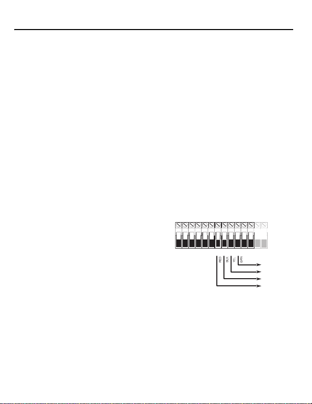
Section 2: Installation et câblage du TR5164
KEYBUS VERS
TR5164
PC1864
Seulement
AC AC + AUX - + BELL -
RED BLK YEL GRN
1 PGM 2 3 PGM 4
Tableau de contrôle
(Rouge)
(Noir)
(Jne)
(Vert)
Cette section décrit comment installer et câbler le module TR5164.
2.1 Déballez le TR5164
Vérifiez que les éléments suivants se trouvent dans la boîte :
• TR5164 PCB • Manuel d’installation
• Coffret en plastique du TR5164
2.2 Trouvez un emplacement pour l’installation du TR5164
REMARQUE: Installez définitivement le récepteur TR5164 et les dispositifs sans fil après avoir fait le
test de portée pour chaque dispositif (Section 2.4, page 28, Section 5.1, page 35).
Trouvez un endroit qui est :
•Sec
• Dans la plage de température de fonctionnement
• Central à l’emplacement proposé de tous les dispositifs sans fil
• Aussi haut que possible. Placez le module aus
premier étage
• Loin des sources d’interf
moteurs électriques, appareils ménagers et dispositif de chauffage ou d’air climatisé, d’objets tels
que des tubulures de chauffage et la plomberie qui pourraient empêcher les ondes
électromagnétiques de passer
• La surface sur laquelle le TR5164 est fixée doit être plate et sans obstr
l’accès à l’arrière du dispositif
érence, notamment de : bruits électriques tels qu’ordinateurs, télévision et
2.3 Connectez le récepteur TR5164
ATTENTION : Coupez toute l’alimentation (CA, CC,
lignes téléphoniques) du panneau lorsque vous connectez
les modules au Keybus.
Branchez le TR5164 au Keybus à quatre fils du panneau
ôle conformément à la Figure 1.
de contr
Une fois le câblage achevé, remettez le système de
sécurité sous tension.
Ensuite, enregistrez et paramétrez les dispos
Vo i r Section 3.1, page 29 pour des instructions.
2.4 Test de portée du récepteur
Le TR5164 fonctionne le mieux à des emplacements où les interférences RF sont minimes. Pour
trouver le meilleur endroit pour installer le dispositif, effectuez le test de portée suivant :
1. Mettez le TR5164 sous tension et mai
2. Si le voyant DEL jaune est allumé, les niveaux
emplacement devrait être trouvé. Si le voyant DEL clignote ou s’il est éteint, l’interférence est
faible et l’emplacement est bon.
si haut et aussi près que possible de la sous-face du
uctions qui pourraient bloquer
itifs sans fil.
Figure 1
ntenez-le à l’emplacement choisi.
d’interférence sont élevés et un nouvel
28

Section 3: Programmation du Récepteur
L’enregistrement consiste à paramétrer le numéro de série électronique (NSÉ) du dispositif dans le
TR5164 de sorte qu’il puisse être identifié lorsqu’un événement est communiqué. Le numéro de série
électronique (NSÉ) est situé au dos de chaque dispositif.
Cette section décrit comment enregistrer et paramétrer :
• les dispositifs sans fil utilisant des zones
• les clés sans fil
Pour de plus amples renseignements sur ces dispositifs, veuillez consulter le mode d’emploi
accompagnant chaque dispositif.
3.1 Enregistrement du clavier sans fil sur le TR5164
Durant la première mise sous tension du panneau d’alarme, une fenêtre de 2 minutes est établie pour
l’enregistrement du clavier sans fil (indiquée par le clignotement des voyants DEL rouge et vert). Si la
fenêtre d’enregistrement expire, mettez le panneau hors tension, puis remettez-le sous tension. Par
défaut, les claviers WT5500 sont automatiquement assignés aux fentes numéro 8 à 5.
Pour enregistrer un clavier :
1. Mettez le système d’alarme sous tension.
2. Mettez le clavier sous tension. Quelques secondes plus tard, « Maintenez [1] et [,] pour
enregistrer le Clavier
3. Appuyez sur les touches [1] et [,] simultanément pour l’enregistrement. « WFKP Enregistrement
réussi » est affiché.
Si le message « Échec d’enregistrement » est affiché, effectuez les opérations suivantes :
• Réessayez l’enregistrement.
• Placez le clavier plus près du panneau de contrôle.
• Vérifiez que les voyants DEL rouge et vert du panneau clignotent. Sinon, déconnectez le panneau
des sources d’alimentation CA et CC, puis reconnectez.
• Vérifiez qu’il n’y a pas d’interférence RF. S’il est le voyant DEL jaune allumé, le trafic RF ou le
niveau de bruit à l’étage est trop élevé.
3.2 Enregistrement rapide des dispositifs sans fil/clavier (WT5500
seulement)
1. Saisissez [,][8][Code Installateur][898]. « Mode d’enregistrement sans fil » est affiché.
2. Activez le dispositif comme indiqué ci-dessous.
•Clavier : Appuyez sur les touches [,] et [1] simultanément.
• Clé sans fil : Appuyez sur une touche quelconque pour activer.
• Détecteurs (Infrarouge passif, Fumée, Bris de vitre) Appuyez sur la touche Autoprotection.
• Répéteur : Appuyez sur la touche Autoprotection. Remarque : Vérifiez que le commutateur DIP
3 sur le répéteur est en position OFF avant l’enregistrement rapide du répéteur.
3. Le numéro de série électronique (NSÉ) est affiché sur le clavier. Saisissez [,] pour confirmer le
NSÉ. Si le NSÉ est faux, appuyez sur [#], et refaites l’étape
4. Après la confirmation de la saisie réussie du NSÉ, le système affiche un message guide pour le
numéro de la zone/de la fente.
• La fente suivante ouverte pour ce type de dispositif est affichée. Appuyez sur [,] pour accepter
ou saisissez un autre numéro la fente.
» est affiché.
2.
29

• Pour le réenregistrement d’une clé sans fil sur un autre système, appuyez sur
simultanément pendant envir
on 3 secondes.
3.3 Changement d’assignation de la fente du clavier sur le TR5164
Par défaut, les claviers WT5500 sont automatiquement assignés aux fentes numéro 8 à 5.
Pour changer le numéro de la f
1. Entrez dans la programmation de l’insta
2. Entrez dans la section [804] - [000]. Un champ à 2 chiffres est affiché.
3. Dans le premier champ saisissez
deuxième champ, saisissez un numéro de fente du clavier de 1 à 8 (par ex., 1,8 représente la
Partition 1, la fente de clavier 8).
4. Inscrivez le numéro de fente assigné dans les feuilles de prog
ce manuel.
5. Après la réassignation d’un clavier, effectuez une
,][8][code de l’installateur][902] et attendez 60 secondes.
[
6. Appuyez deux fois sur [#] pour sortir après 60 secondes.
ente par défaut pour un clavier WT5500 :
llateur [,][8][code de l’installateur].
1 pour la Partition 1 (seule la partition 1 est permise). Dans le
rammation qui se trouvent au dos de
réinitialisation de supervision en saisissant
3.4 Enregistrement manuel des dispositifs/claviers sans fil
Pour enregistrer manuellement un dispositif sans fil bidirectionnel :
1. Saisissez [
2. Saisissez la zone/fente à 3 chiffres correspondant a
3. Saisissez le numéro de série du dispositif. Sur les claviers PK, c’est une saisie à 6 chiffres. Lorsque
4. Inscrivez le numéro de série et le numér
5. Répétez les étapes 2 à 4 jusqu’à l’enregistrement de tous les dispositifs sans fil.
6. Saisissez [#] pour sortir.
,][8][Code Installateur][804].
Capteurs sans fil, pendentif
Clé sans fil [804][101]-[116] pour une clé sans fil numéros 01- 16
Clavier sans fil [804][029]-[032]
REMARQUE: Des dispositif
même zone. Les modules d’extension de zone PC5108 occupent les zones en 2 groupes de 4 (par
ex., zones 9-12 et zones 13-16., zones 9-12 et zones 13-16). Aucune des zones affectées à un
odule PC5108 ne peut être utilisée pour des dispositifs sans fil. Pour de plus amples
m
renseignements sur l’affectation de zone, consultez le manuel d’installation du système. Une clé
sans fil ne peut être affectée qu’à une partition (partition 1 par défaut). Pour assigner les clés à une
rtition différente, voir « [804][183] Affectations de partition de Clé sans fil (1-16)» à la page 45.
pa
vous saisissez un NSÉ à 8 chif
c’est une saisie à 8 chiffres. Lorsque vous saisissez un NSÉ à 6 chiffres, saisissez 00 pour les deux
premiers chiffres. Les numéros de série incluent des chiffres hexadécimaux. Pour basculer des
entrées entre décimales et hexadécimales, appuyez sur [
programmation des chiffres hexadécimaux, consultez le manuel d’installation du système. Le
dispositif est à présent enregistré dans le système.
programmation qui se trouvent au dos de ce manuel.
REMARQUE: La progr
dispositifs sans fil fonctionnent correctement (voir Section 4.1, page 32 ).
s, répéteurs [804][001]-[064] (sauf [029]-[032])
s câblés et des dispositifs sans fil ne peuvent pas être assignés à la
fres, ne saisissez pas les deux premiers chiffres. Sur les claviers WT,
ammation de la zone et de la partition doit être achevée pour que les
u type de dispositif :
,]. Pour des instructions sur la
o de zone à laquelle il est affecté dans les feuilles de
30

REMARQUE: (Pour les installations non homologuées UL) Pour les répéteurs et les claviers
sans fil, le type de zone
courant ou la pile faible ne sont pas signalées à la station centrale. Le panneau d’alarme n’indique
pas un trouble pour la zone, mais indique qu’elle est ouverte. Choisissez la caractéristique
«
Armement forcé » pour cette zone. Paramétrez un texte de zone pour identifier le WS4920 ou le
WT5500. Ex., « Rptr 1 Pwr Trbl. »
REMARQUE: (Pour les installations homologuées UL) Si la panne de courant et la pile faible
doivent être signalées à la station centrale utilisez une zone de type 24
caractéristique Audible est réglée à Silence.
Pour annuler un dispositif sans fil :
1. Sur un clavier du système, saisissez [,][8][code de l’installateur].
2. Entrez dans la section de programmation [804].
3. Saisissez le numéro à 3 chiffres correspondant à la zone sur laquelle vous désirez annuler le
dispositif.
4. Paramétrez le NSÉ comme [00000000]. Le dispositif est annulé.
5. Saisissez [#] pour sortir.
Une fois que tous les dispositifs sans fil sont enregistrés, paramétrez le système pour qu’il fonctionne
avec les dispositifs. Voir 4.1 « Programmation des zones et de partitions» à la page 32 pour de plus
amples renseignements.
26 non-alarme est recommandé. Avec ce type de zone, la panne de
h. Vérifiez que la
31

Section 4: Autre programmation
4.1 Programmation des zones et de partitions
Une fois que tous les dispositifs sans fil sont enregistrés, achevez la programmation de zone sur le
système. Vérifiez que les options de programmation suivantes sont remplies correctement pour chaque
zone sans fil
• Activez les zones et/ou assignez les zones à une ou plusieurs partitions (sections de programmation
• Paramétrez la définition de chaque zone (sections de programmation [001]-[004]).
• Activez l’attribut de zone sans fil pour chaque zone sans fil (sections [101]-[164]).
Pour de plus amples renseignements sur les sections de programmation ci-dessus, consultez le manuel
d’installation du système.
4.2 Activation de la supervision du TR5164
Le panneau de contrôle peut surveiller le récepteur TR5164 par l’intermédiaire du Keybus après
l’enregistrement d’au moins un dispositif sur le module (
Pour activer la supervision du module :
1. Enregistrez le premier dispositif.
2. Sortez et rentrez dans la programmation de l’installateur [,][8].
3. Entrez dans la section de programmation [902]. Attendez 60 secondes environ pendant que le
4. Pour sortir, appuyez sur [#].
Le système génère un problème général de supervision du système si le module est retiré du Keybus. Si le
module TR5164 doit être retiré du système existant, désactivez d’abord la supervision du TR5164.
REMARQUE: L’annulation de tous les dispositifs du TR5164 ou la mise aux valeurs par défaut du
TR5164 provoque une anomalie de supervision.
Pour désactiver la supervision du TR5164 :
1. Déconnectez le TR5164 du Keybus.
2. Saisissez [,][8][Code Installateur][804].
3. Saisissez [902]. Le panneau de contrôle efface toute la supervision et cherche à nouveau les
4. Pour sortir, appuyez sur [#].
Pour vérifier la supervision du panneau de contrôle pour le TR5164 (pas offert sur les claviers
WT5000)
1. Saisissez [,][8][Code Installateur][804].
2. Saisissez [903] pour afficher tous les modules. Sur le clavier DEL à 32 zones, le voyant [17]
3. Pour sortir, appuyez sur [#].
Si le TR5164 n’est pas détecté, vérifiez l’un des problèmes suivants :
• le module n’est pas bien connecté au Keybus
• le câblage du Keybus est défectueux
• l’alimentation du module est insuffisante
• aucun dispositif n’a été enregistré sur le TR5164
:
[202] à [265]).
Section 3.1, page 29).
système cherche les modules connectés.
modules branchés sur le système. La recherche prend environ 60 secondes.
:
indique que le TR5132 est présent sur le système. Sur les claviers ACL, faites défiler jusqu’au
moment où le nom du module TR5164 est affiché.
32

Interférence
Un brouillage RF se produit lorsqu’une transmission non voulue d’une source extérieure se produit
dans la zone de fonctionnement du récepteur qui empêche le fonctionnement d’un ou plusieurs
dispositifs.
Le récepteur a la capacité de détecter une situation de brouillage RF et d’indiquer un problème
approprié au panneau de contrôle. Cette fonction peut être désactivée dans la section [804][900],
option [7].
4.3 Activation de la supervision des zones sans fil
Chaque dispositif sans fil (sauf les clés sans fil) envoie périodiquement un signal de supervision. Si le
récepteur ne reçoit pas un signal dans le délai paramétré pour la fenêtre de Supervision sans fil, il
déclenche un défaut de supervision.
REMARQUE: Pour que la supervision à distance fonctionne, vous activez la caractéristique de zone
sans fil sur toutes les zones sans fil (sections [101] à [164], option [8] ON).
Pour paramétrer la fenêtre de supervision sans fil :
1. Saisissez [,][8][Code installateur] pour accéder à la programmation de l’installateur.
2. Saisissez [804] pour entrer dans la programmation du module TR5164.
3. Saisissez la section [081].
4. Saisissez le temps prévu pour la fenêtre de supervision. La fenêtre est paramétrée par incrément
de 15 minutes. Les valeurs par défaut sont :
• 96 (x15minutes), ce qui équivaut à 24 heures pour la version d’Amérique du Nord, ou
• 8 (x15minutes), ce qui équivaut à 2 heures pour la version de l’Union européenne
Les valeurs possibles sont (4) à (96) ce qui équivaut de 1 heure à 24 heures.
5. Pour sortir, appuyez sur [#].
REMARQUE: La supervision doit être activée pour Panne RF.
Pour activer/désactiver la zone de supervision :
1. Saisissez [,][8][Code installateur] pour accéder à la programmation de l’installateur.
2. Saisissez [804] pour entrer dans la programmation du module TR5164.
3. Saisissez les sections [082]-[089]. Activez ou désactivez la supervision pour chaque zone sans fil
en mettant chaque option pertinente à ON ou à OFF. La supervision est activée par défaut pour
toutes les zones sans fil.
4. Pour sortir, appuyez sur [#].
4.4 Signalisation des ouvertures/fermetures par les clés sans fil
L’activation d’ouvertures, de fermetures et de sortie de commande (par ex., ouverture d’une porte de
garage) par des clés sans fil individuelles peut générer une signalisation sur certains panneaux de
contrôle.
Pour activer la signalisation pour les ouvertures/fermetures de clé sans fil :
1. Paramétrez un code d’accès valide pour chaque clé (en utilisant [,][5] programmation code
d’accès).
REMARQUE: Paramétrez ces codes d’accès sur le système après avoir connecté le TR5164 au
Keybus (
Section 2.4, page 28). Codes d’accès 17 – 32 sont réservés pour les clés sans fil 01-16
respectivement. Consultez le manuel d’installation du panneau d’alarme pour des renseignements
sur le code de programmation d’accès.
33

2. Paramétrez un code de signalisation d’ouverture et de fermeture pour chaque clé ([339]-[340],
[342]-[343]).
3. Désactivez l’option Armement rapide dans la section [015] option [4] du programmation du
panneau de contrôle.
REMARQUE: Pour assurer qu’une clé sans fil non identifiée ne peut pas désarmer le système,
désactivez la section [017], option [1] dans la programmation de l’installateur.
4.5 Programmation des boutons de fonction de la clé sans fil
Les clés sans fil ont quatre ou six boutons de fonction paramétrables. Des fonctions par défaut ont été
assignées, mais d’autres fonctions peuvent être paramétrées si désiré.
REMARQUE: Les clés sans fil bidirectionnelles (WT4989) ne peuvent être assignées qu’à la
partition
1. Les clés sans fil ne fonctionnent pas lorsque la partition est suspendue ou en cours de
programmation.
Pour paramétrer les boutons de fonction des clés sans fil :
1. Sur un clavier du système, saisissez [,][8][code de l’installateur].
2. Entrez dans la section de programmation [804].
3. Entrez dans la section de programmation [141] à [156] pour des clés 1 - 16.
4. Pour chacun des boutons disponibles sur la clé sans fil, saisissez le numéro à 2 chiffres
correspondants à la fonction sélectionnée. Voir
à la page 43 pour une liste des options de fonction de la clé.
5. Enregistrez tous les choix de programmation sur les feuilles de travail au dos du manuel.
6. Pour sortir, appuyez sur [#].
Pour de plus amples renseignements sur la programmation des boutons de fonction des clés sans fil,
consultez la notice d’installation de la clé sans fil.
« Options des boutons de fonction des clés sans fil»
4.6 Valeurs par défaut du logiciel TR5164
Revenir aux réglages des valeurs par défaut du PC5164 est un moyen rapide de retirer tous les
dispositifs enregistrés sur le système et de restaurer toute la programmation dans la section [804].
REMARQUE: Effectuer cette procédure ne réinitialise pas les autres sections de programmation sur le
panneau de contrôle. De même, la réinitialisation du panneau de contrôle aux valeurs par défaut
n’affecte pas la programmation du TR5164.
Pour réinitialiser la programmation du TR5164 aux valeurs par défaut :
1. Saisissez [,][8][Code de l’installateur].
2. Entrez dans la section de programmation [996].
3. À nouveau, saisissez le code de l’installateur, suivi par [996]. Le logiciel du TR5164 est réinitialisé
aux valeurs par défaut.
4. Pour continuer la programmation du dispositif, sortez de la programmation de l’installateur en
appuyant sur [#] [
Pour des instructions sur la réinitialisation du panneau de contrôle ou tout autre module connecté aux
paramètres par défaut, voir le manuel d’installation du panneau de contrôle.
,][8][Code de l’installateur].
34

Section 5: Essai et installation
5.1 Essai de réception des dispositifs sans fil
L’essai du placement proposé de chaque dispositif sans fil avant de le fixer est très important. En
suivant ces directives, vous effectuez l’essai de l’intensité du signal entre le TR5164 et les dispositifs
sans fil.
Tous les dispositifs peuvent être testés ensemble
REMARQUE: A
l’installateur puis y rentrer au moins une fois avant d’effectuer un test de portée.
Pour effectuer un test de portée global :
1. Temporairement, placez les dispositifs sans fil aux endr
2. Sur un clavier du système, tapez [,][8][code de l’installateur].
3. Pour les claviers WT5500, entrez dans la section [
les dispositifs sans fil sont testés en même temps.
4. Pour les claviers PK, par
la section [904], puis saisissez le numéro de zone d’un dispositif sans fil quelconque.
5. Activez le(s) dispositif(s) conformém
pertinente. Pour les claviers sans fil bidirectionnels, appuyez sur une touche quelconque sauf la
touche #. Le nom du dispositif et le numéro de zone sont affichés sur l’écran LCD.
Lisez les résultats d’essais sur le clavier :
6. Activez le dispositif jusqu’à l’obtention de trois de 3 « bons » résultats d’affilée.
7. Fixez les dispositifs sans fil où les résultats
résultat doivent être déplacés. Il est possible que le dispositif ne doive être déplacé que de
quelques centimètres pour rectifier un mauvais résultat.
Ne fixez pas un dispositif à un endroit où un « mauvais » résultat est indiqué.
8. Effectuez l’étape 4 pour chaque dispositif enregistré sur le TR5164.
Attendez que le résultat du test de portée d
l’essai du suivant.
Continuez à tester les dispositifs jusqu’à ce que le TR5164 et le
des endroits bons. Si le test de plusieurs dispositifs sans fil donne de « mauvais » résultats, voyez
la possibilité de déplacer le récepteur TR5164 à un endroit différent (voir Section 2.2, page 28
pour des conseils sur la manière de tr
9. Pour sortir de du test de portée et revenir à la programmation de l’installateur, appuyez deux fois
sur [#].
Testez les dispositifs individuels
1. Placez temporairement le dispositif à l’e
2. Sur un clavier du système, tapez [
3. Entrez dans la section de programmation [9
vérifiez que l’option 8 de la section [804][900] est désactivée (OFF).
4. Saisissez le numéro de zone à 2 chiffres pour le dispositif.
près l’enregistrement des dispositifs sans fil, on doit sortir de la Programmation de
amétrez l’option 8 de la section [804][900] à activée (ON). Entrez dans
Résultat Clavier DEL Clavier LCD Indicateur sonore/Sonnerie
Bon Voyant 1 allumé continu « Bon » 1 Bip/Bruit de sonnerie
Mauvais Voyant 3 allumé continu « Mauvais » 3 Bips/Bruits de sonnerie
(test de portée global) ou individuellement.
oits d’installation choisis.
904], puis saisissez [00]. Dans ce mode, tous
ent à la description contenue sur la fiche d’installation
sont bons. Les dispositifs indiquant un mauvais
’un dispositif soit montré/entendu avant de passer à
s dispositifs soient tous placés à
ouver un emplacement approprié).
ndroit où vous préféreriez l’installer.
,][8][code de l’installateur].
04] pour les dispositifs sans fil. Pour les claviers PK,
35

5. Activez le dispositif jusqu’à l’affichage d’un résultat sur le clavier ou un bruit de clavier ou une
Languette
détachable
Languette
détachable
sonnerie.
6. Pour tester un autre dispositif, appuyez un
tester les dispositifs jusqu’à ce que le TR5164 et les dispositifs soient tous placés à des endroits
acceptables.
Si le test de plusieurs dispositifs sans fil donne de « mauvais » résultats, voyez la possibilité de
cer le récepteur TR5164 à un meilleur endroit (voir Section 2.2, page 28 pour des conseils sur
dépla
la manière de trouver un emplacement p
7. Pour sortir du test de portée et de la programmation de l’installateur, appuyez deux fois sur [#].
Test individuel des clés sans fil
N’utilisez pas l’essai de dispositif individuel décrit ci-dessus pour te
que le récepteur TR5164 reçoit les transmissions de ces dispositifs, utilisez les boutons de fonction sur
les clés sans fil à des endroits différents dans toute l’installation.
REMARQUE: Pour qu’elles fonctionnent,
appuyant sur une touche quelconque.
e fois sur [#], puis répétez les étapes 4 - 5. Continuez de
our le TR5164).
ster les clés sans fil. Afin d’assurer
les clés sans fil bidirectionnelles doivent être activées en
5.2 Installation
Une fois que la réception entre le TR5164 et tous les dispositifs sans fil a été testée et vérifiée (Section
5.1, page 35), faites l’installation comme suit :
TR5164
1. Tirez les fils du Keybus par les trous situés au fond du coffret ou par les languettes détachables sur
les côtés.
2. Fixez fermement le coffret au mur à l’aide des deux (
2) vis fournies. Voir Figure 2.
Figure 2
36

Dispositifs sans fil
Installez les dispositifs sans fil une fois que le test de portée décrit à la section 5.1 a été effectué et que
trois «
bons » résultats d’affilée ont été obtenus pour chaque dispositif. Voir la notice d’installation de
chaque dispositif pour les instructions de montage.
Maintenant que le TR5164 et vos dispositifs sans fil sont installés et qu’ils fonctionnent correctement,
lisez
Section 6.1, page 38 pour des renseignements sur les problèmes qui peuvent survenir avec les
dispositifs sans fil et le remplacement de piles.
37

Section 6: Remarques supplémentaires
6.1 Situations de trouble
Le panneau de contrôle surveille constamment les divers problèmes qui problèmes éventuels. Si un
problème est détecté, le clavier émet un bip et le voyant «
afficher les problèmes.
Les problèmes éventuels suivants s’appliquent au TR5164 et/ou à tout dispositif enregistré.
• Brouillage RF (sur les panneaux Power v.2.01 et antécédent) - Ce trouble est généré lorsque le
TR5164 détecte une situation de Brouillage RF.
• Supervision de module - Ce problème est généré si le panneau perd la communication avec un
module quelconque connecté au Keybus. La mémoire tampon des événements enregistre une
description détaillée de l’événement.
• Pile de Dispositif sans fil faible - Ce problème est provoqué lorsqu’un dispositif sans fil indique que
sa pile est faible. Appuyez sur [7] une, deux, ou trois fois pour visualiser quel dispositif a une pile
faible. Un clavier DEL indique la panne de pile en utilisant les voyants de zone
6.2, page 38 pour de plus amples renseignements.
• Autoprotection de Zone - Ce problème est provoqué lorsqu’un dispositif sans fil attribué est retiré de
son emplacement.
• Défaut de zone - Chaque dispositif sans fil envoie un signal de supervision toutes les 64 minutes (15
minutes pour l’Union européenne). Si le récepteur ne reçoit pas un signal dans le délai programmé
pour la fenêtre de surveillance de zone sans fil, un défaut de zone est généré.
• Panne RF (UE seulement) - Chaque zone sans fil envoie un signal de supervision toutes les 15
minutes. Si le récepteur ne reçoit pas un signal dans les 15 minutes, un trouble Panne RF est généré
pour cette zone.
REMARQUE: Lorsqu’il y a un trouble panne de ca et pile faible du clavier WT5500 et du répéteur
sans fil le panneau d’alarme indique la zone correspondante comme étant ouverte.
6.2 Transmission pile faible zone sans fil
L’état de la pile de chacun des dispositifs est régulièrement communiqué au panneau d’alarme. Si une
pile est faible, le système enregistre un Trouble pile faible pour le dispositif.
Le système retarde la signalisation de l’événement à la station centrale pendant le nombre de jours
programmé dans la section [377] du panneau. Cela évite la signalisation de l’événement si l’utilisateur
a appris comment remplacer les piles.
Remplacement des piles dans les dispositifs sans fil
1. Consultez les instructions d’installation de la pile dans la Notice d’installation de chaque dispositif.
Lorsque vous installez de nouvelles piles, vérifiez que la polarité est respectée.
2. Lorsque des nouvelles piles sont en place et que l’autoprotection est rétablie, le trouble pile faible
est effacé et le dispositif devrait fonctionner normalement.
Trouble » s’allume. Appuyez sur [,][2] pour
1 à 8. Voir Section
38

Section 7: Diagnostic de pannes
1. Lorsque je tape le numéro de zone à trois (3) chiffres pour ajouter un dispositif sans fil, le
clavier émet un long bip.
Les NSÉ ne peuvent être entrés que lorsqu’un récepteur sans fil TR5164 est connecté au Keybus.
Vo i r
Section 2.3, page 28 pour des instructions sur la manière d’installer et de câbler le TR5164
module.
2. J’ai un tapé un NSÉ pour le dispositif, mais lorsque je l’ai activé, le clavier n’indique pas
que la zone est ouverte.
Vérifiez les éléments suivants :
• Vérifiez que le numéro de série électronique a été tapé correctement.
• Assurez-vous que la zone est activée pour la partition (si la programmation de partition est
utilisée).
• Assurez-vous que la zone sans fil n’est pas affectée à une zone utilisée par des modules
PC5108, une zone à bord ou une zone de clavier.
• Assurez-vous que la zone est programmée pour autre chose que « Fonctionnement nul », et que
l’attribut de la zone sans fil est activé.
3. Lorsque je fais un test de portée pour un module, je n’obtiens pas de résultats ou des
«
mauvais » résultats.
Vérifiez les éléments suivants (voir Section 5.1, page 35 pour de plus amples renseignements sur
le test de portée des dispositifs) :
• Vérifiez que la zone correcte est testée.
• Vérifiez que le bon numéro de série électronique a été entré lors de l’enregistrement du
dispositif.
• Vérifiez que le dispositif est dans la plage de portée du TR5164. Essayez de tester les
dispositifs dans la même pièce que le récepteur.
• Confirmez que le TR5164 est bien connecté au Keybus (voir Section 2.4, page 28 pour les
instructions d’installation et de câblage du TR5164).
• Vérifiez que la zone est testée correctement (voir Section 5.1, page 35 pour les instructions de
test).
• Vérifiez que les piles sont bonnes et qu’elles sont installées correctement.
• Regardez s’il y a de gros objets en métal qui pourraient empêcher le signal d’atteindre le
TR5164.
Le dispositif doit être situé à l’endroit où des résultats « bons » sont régulièrement obtenus. Si
plusieurs dispositifs montrent des résultats « mauvais », déplacez le récepteur. Voir Section 2.2,
page 28 pour des conseils sur la manière de trouver un bon emplacement pour le TR5164.
4. Le voyant DEL sur le détecteur de mouvement ne s’allume pas lorsque je marche devant le
dispositif.
Le voyant DEL est uniquement destiné aux tests de portée. Voir la notice du PIR sans fil pour des
instructions sur les tests de portée.
39

Section 8: Feuilles de programmation
Programmation du TR5164 sans fil
Utilisez les feuilles de travail suivantes pour enregistrer
fil pour consultation ultérieure.
NA = paramètre par défaut pour l’Amérique du
[804][000] Programmation de la partition et de l’fente du clavier sans fil
Clavier Défaut
WT5500 no 1
WT5500 no 2
WT5500 no 3
WT5500 no 4
[804][001]-[064] Programmation de zone sans fil
claviers sans fil)
Les claviers sans fil 1-4 doivent être enregistrés dans les zones 29-32 respectivement. Tous les autres
dispositifs sans fil peuvent être attribués dans n’importe lesquelles des 60 zones restantes.
Valeur par défaut = 00000000
REMARQUE: Le premier chiffre représente la partition
(seule la partition 1 est appuyée). Le deuxième chiffre indique
1,8
le numéro de la fente du clavier. (par ex., 1,8 = partition 1, fente
1,7
8). Les claviers sans fil peuvent être programmés dans les
fentes 1-8. Les fentes par défaut sont 8, 7, 6, 5.
1,6
1,5
Zone Zone
[001] [012]
[002] [013]
[003] [014]
[004] [015]
[005] [016]
[006] [017]
[007] [018]
[008] [019]
[009] [020]
[010] [021]
[011] [022]
les options de programmation du dispositif sans
Nord; UE= paramètre par défaut pour l’Europe
(pour les dispositifs, les répéteurs et les
40

Zone Zone
[023] [044]
[024] [045]
[025] [046]
[026] [047]
[027] [048]
[028] [049]
Clavier sans fil 1-4
[029] [050]
[030] [051]
[031] [052]
[032] [053]
[033] [054]
[034] [055]
[035] [056]
[036] [057]
[037] [058]
[038] [059]
[039] [060]
[040] [061]
[041] [062]
[042] [063]
[043] [064]
41

[804][081] Fenêtre de supervision sans fil (Valeur par défaut = 96)
La fenêtre est paramétrée par
La programmation par défaut est :
• 96 (x15minutes), ce qui équivaut à 24 heures (Amérique du Nord), ou
• 8 (x15minutes), ce qui équivaut à 2
Les valeurs possibles sont (004) à (096) ce qui équivaut de 1 heure à 24 heures.
REMARQUE: Pour
paramétrez la fenêtre de surveillance à 16 heures. Pour les applications homologuées UL/ULC
intrusion résidentielles paramétrez la valeur à 96.
[804][082]-[089] Supervision transmetteur de zone
[082] Zone 1-8 [083] Zones
Opt Déf. Déf. Déf. Déf.
1 Zone 1 Zone 9 Zone 17 Zone 25
2 Zone 2 Zone 10 Zone 18 Zone 26
3 Zone 3 Zone 11 Zone 19 Zone 27
4 Zone 4 Zone 12 Zone 20 Zone 28
5 Zone 5 Zone 13 Zone 21 Zone 29
6 Zone 6 Zone 14 Zone 22 Zone 30
7 Zone 7 Zone 15 Zone 23 Zone 31
8 Zone 8 Zone 16 Zone 24 Zone 32
[086] Zone
Opt Déf. Déf. Déf. Déf.
1 Zone 33 Zone 41 Zone 49 Zone 57
2 Zone 34 Zone 42 Zone 50 Zone 58
3 Zone 35 Zone 43 Zone 51 Zone 59
4 Zone 36 Zone 44 Zone 52 Zone 60
5 Zone 37 Zone 45 Zone 53 Zone 61
6 Zone 38 Zone 46 Zone 54 Zone 62
7 Zone 39 Zone 47 Zone 55 Zone 63
8 Zone 40 Zone 48 Zone 56 Zone 64
REMARQUE: Les ém
section.
les applications homologuées UL/ULC Intrusion et Incendie résidentielles,
33-40
[087] Zones
etteurs de panique NE sont PAS supervisés et doivent être désactivés dans cette
incrément de 15 minutes.
heures (Union européenne).
Options
[084] Zones
9-16
41-48
[088] Zones
17-24
49-56
[085] Zones
25-32
[089] Zones
57-64
42

[804][101]-[116] Numéros de série des clés sans fil
[101] [109]
[102] [110]
[103] [111]
[104] [112]
[105] [113]
[106] [114]
[107] [115]
[108] [116]
Options des boutons de fonction des clés sans fil
Entrée Description de la clé Entrée Description de la clé
00 Clé nulle 18 Global MES Totale
01-02 Pour utilisation future 19 [
,][7][3] Sortie de commande no 3
03 MES Partielle 20 Pour utilisation future
04 MES Totale 21 [
05 [
,][9] Armement sans
,][7][4] Sortie de commande no 4
22 Désarmement global
Temporisation d’entrée
06 [
,][4] Carillon de porte
23-26 Pour utilisation future
MARCHE/ARRÊT
7-12 Pour utilisation future 27 MHS (OFF)
13 [
,][7][1] Sortie de commande no 1 28 Pour utilisation future
14 [
,][7][2] Sortie de commande no 2 29 Alarme auxiliaire
15 MES partielle Globale 30 Alarme panique
16 [
,][0] Sortie rapide 31-33 Pour utilisation future
17 [
,][1] Activer Partielle/Totale
REMARQUE: L
désarmement global.
es clés sans fil doivent avoir un code d’accès pour les fonctions d’armement/
43

[804][141]-[156] pour les boutons de fonction des clés sans fil.
Fonction 1 Fonction 2 Fonction 3 Fonction 4 Fonction 5 Fonction 6
Défaut 0,3 Défaut 0,4 Défaut 2,7 Défaut 3,0 Défaut 1,3 Défaut 1,4
[141] Clé 1
[142] Clé 2
[143] Clé 3
[144] Clé 4
[145] Clé 5
[146] Clé 6
[147] Clé 7
[148] Clé 8
[149] Clé 9
[150] Clé 10
[151] Clé 11
[152] Clé 12
[153] Clé 13
[154] Clé 14
[155] Clé 15
[156] Clé 16
REMARQUE: Les fonctions 5 et 6 sont exclusivement pour le WT4989.
44

[804][181]-[182]Active/Désactive les clés sans fil bidirectionnelles 1-16
[804][181] Active/Désactive les clés sans
il bidirectionnelles 1-8
f
Opt Déf. Clé ON OFF Opt Déf. Clé ON OFF
1 Off 1
2 Off 2
3 Off 3
4 Off 4
5 Off 5
6 Off 6
7 Off 7
8 Off 8
[804][183] Affectations de partition de Clé sans fil (1-16)
(Valeur par défaut = 01)
Clé 1 Clé 9
Clé 2 Clé 10
Clé 3 Clé 11
Clé 4 Clé 12
Clé 5 Clé 13
Clé 6 Clé 14
Clé 7 Clé 15
Clé 8 Clé 16
[804][800] Options diverses de clavier
Option Valeur par
1 On Carillon à l’ouverture Activé
2 Off
3-8 Off
Bidirectionnelle Unidirectionnelle
Bidirectionnelle Unidirectionnelle
Bidirectionnelle Unidirectionnelle
Bidirectionnelle Unidirectionnelle
Bidirectionnelle Unidirectionnelle
Bidirectionnelle Unidirectionnelle
Bidirectionnelle Unidirectionnelle
Bidirectionnelle Unidirectionnelle
défaut
Option ON Option OFF
Carillon à la fermeture ActivéCarillon à la fermeture Désactivé
Future Utilisation
[804][182] Active/Désactive les clés sans
fil bidirectionnelles 9-16
1 Off 9
2 Off 10
3 Off 11
4 Off 12
5 Off 13
6 Off 14
7 Off 15
8 Off 16
Bidirectionnelle Unidirectionnelle
Bidirectionnelle Unidirectionnelle
Bidirectionnelle Unidirectionnelle
Bidirectionnelle Unidirectionnelle
Bidirectionnelle Unidirectionnelle
Bidirectionnelle Unidirectionnelle
Bidirectionnelle Unidirectionnelle
Bidirectionnelle Unidirectionnelle
Carillon à l’ouverture Désactivé
45

[804][801]-[864] Programmation personnalisée du carillon de porte
Opt Valeur par défaut Description
1 On 6 Bips
2 Off Son « Bing-Bing »
3 Off Son « Ding-Dong »
4 Off Tonalité d’alarme
5-8 Off Future Utilisation
[801] [815] [829] [843] [857]
1 2 3 4 1 2 3 4 1 2 3 4 1 2 3 4 1 2 3 4
[802] [816] [830] [844] [858]
1 2 3 4 1 2 3 4 1 2 3 4 1 2 3 4 1 2 3 4
[803] [817] [831] [845] [859]
1 2 3 4 1 2 3 4 1 2 3 4 1 2 3 4 1 2 3 4
[804] [818] [832] [846] [860]
1 2 3 4 1 2 3 4 1 2 3 4 1 2 3 4 1 2 3 4
[805] [819] [833] [847] [861]
1 2 3 4 1 2 3 4 1 2 3 4 1 2 3 4 1 2 3 4
[806] [820]
1 2 3 4 1 2 3 4 1 2 3 4 1 2 3 4 1 2 3 4
[807] [821] [835] [849] [863]
1 2 3 4 1 2 3 4 1 2 3 4 1 2 3 4 1 2 3 4
[808] [822] [836] [850] [864]
1 2 3 4 1 2 3 4 1 2 3 4 1 2 3 4 1 2 3 4
[809] [823] [837] [851]
1 2 3 4 1 2 3 4 1 2 3 4 1 2 3 4
[810] [824] [838] [852]
1 2 3 4 1 2 3 4 1 2 3 4 1 2 3 4
[811] [825] [839] [853]
1 2 3 4 1 2 3 4 1 2 3 4 1 2 3 4
[812] [826] [840] [854]
1 2 3 4 1 2 3 4 1 2 3 4 1 2 3 4
[813] [827] [841] [855]
1 2 3 4 1 2 3 4 1 2 3 4 1 2 3 4
[814] [828] [842] [856]
1 2 3 4 1 2 3 4 1 2 3 4 1 2 3 4
`
[834] [848] [862]
(pour les zones 1-64)
46

[804][900] Options Générales sans fil
Option Défaut Option ON Option OFF
AN UE
1-2 Off OffFuture Utilisation
3 On Off
4 Off Off
5 On Off
6 Off Off
7 On Off
8 Off Off
REMARQUE: Pour les installati
activée - Section [804][900] option 7 OFF.
[804] Test de portée des dispositifs sans fil
8.1 Pour des détails, voir « Testez les dispositifs individuels» à la page 35.
[996] RAZ de tous les textes paramétrables aux valeurs par défaut
Entrer dans cette section et appuyer sur [
dans le langage actif à ce moment-là. Les sections de configuration du clavier ne sont pas touchées.
Autoprotection murale
désactivée
Autoprotection boîtier désactivéAutoprotection boîtier activé
Absence d’activité radio
désactivé
Future Utilisation
Brouillage RF Désactivé
Test de portée Global (pour les
claviers PK seulement)
ons homologuées UL, la fonction Détection brouillage RF doit être
,] remet tous les textes paramétrables du système à RAZ
Future Utilisation
Autoprotection murale activée
Absence d’activité radio activé
Future Utilisation
Brouillage RF Activé
Essai de placement individuel
47

Garantie limitée
Digital Security Controls garantit le produit contre toute défectuosités matérielles et d'assemblage dans des conditions normales d'utilisation, à
l'acheteur original pendant une période de douze mois à partir de la date d'achat. Pendant la période de garantie, Digital Security Controls
s'engage, à son choix, à réparer ou à remplacer tout matériel défectueux dès son retour à un dépôt de réparation, sans frais de main d'oeuvre et
matériels. Tout remplacement et/ou réparation sont garantis pendant le reste de la durée de la garantie originale ou quatre-vingt dix (90) jours,
selon la plus longue. L'acheteur original doit avertir Digital Security Controls par courrier que le matériel ou l'assemblage est défectueux ; dans
tous les cas, cette notification doit être reçue avant l'expiration de la période de garantie. Il n'y a absolument aucune garantie sur les logiciels et
tous les logiciels sont vendus comme licence d'utilisateur dans le cadre des termes du contrat de licence du logiciel fourni avec le produit. Le
client assume toute la responsabilité pour la sélection, installation, et l'entretien de tout produit acheté auprès de DSC. Les produits personnalisés
ne sont garantis que dans la mesure où ils ne fonctionnent pas à la livraison. Dans ce cas, DSC peut, à son choix, remplacer le produit ou crédit
le client.
Garantie internationale
La garantie pour les clients internationaux est la même que pour tous les clients au Canada et aux Etats-Unis, sauf que Digital Security Controls
ne sera pas tenu responsable des frais de douanes, taxes ou TVA qui pourraient être dus.
Procédure pour la garantie
Pour obtenir un service sous garantie, veuillez retourner les produit(s) en question au point d'achat. Tous les distributeurs et vendeurs autorisés
ont un programme de garantie. Quiconque retourne des marchandises à Digital Security Controls doit obtenir au préalable un numéro d'autorisation. Digital Security Controls n'acceptera aucun envoi pour lequel une autorisation préalable n'aura pas été obtenue.
Conditions d'annulation de la garantie
Cette garantie ne s'applique qu'aux vices de matériels et d'assemblage liés à une utilisation normale. Elle ne couvre pas :
• les dommages encourus lors de l'expédition ou la manutention ;
• les dommages causés par un désastre tel qu'un incendie, inondation, vent, tremblement de terre ou foudre ;
• les dommages dus à des causes hors de contrôle de Digital Security Controls tels qu'une tension excessive, choc mécanique ou dégât des
eaux ;
• les dommages causés par attachement non autorisé, changements, modifications ou objets étrangers ;
• les dommages causés par des périphériques (à moins que de tels périphériques n'aient été fournis par Digital Security Controls.) ;
• les défauts causés par l'impossibilité de fournir un environnement d'installation adapté aux produits ;
• les dommages causés par l'utilisation des produits pour des usages autres que ceux pour lesquels ils ont été conçus ;
• les dommages découlant d'un mauvais entretien ;
• les dommages provenant de tout autre mauvais traitement, manutention ou utilisation des produits.
Éléments non couverts par la garantie
En plus des éléments qui annulent la garantie, la garantie ne couvrira pas : (i) les frais de transport au centre de réparation ; (ii) les produits qui
ne sont pas identifiés avec l'étiquette de produit de DSC et un numéro de lot ou un numéro de série ; (iii) les produits démontés ou réparés de
manière qui affecte la performance ou qui empêche une inspection ou un test adéquats afin de vérifier toute réclamation au titre de la garantie.
Les cartes d'accès ou insignes renvoyés pour être remplacées au titre de la garantie seront remplacées ou créditées selon le choix de DSC. Les
produits qui ne sont pas couverts par cette garantie ou qui ne sont plus garantis parce qu'ils sont trop vieux, qu'ils ont été mal utilisés ou endom
magés, seront examinés et une devis de réparation sera fourni. Aucune réparation ne sera effectuée avant la réception d'un bon de commande
valable envoyé par le client et d'un numéro d'autorisation de renvoi de marchandise (RMA) envoyé par le service client de DSC.
S'il y a un problème de réparation du produit après un nombre raisonnable de tentatives au titre de la présente garantie, les obligations contractuelles de la société Digital Security Controls seront limitées au remplacement du produit, comme seule réparation de l'inobservation de la garantie. En aucun cas Digital Security Controls ne sera tenu responsable des dommages particuliers, accidentels ou indirects basés sur l'inobservation
de la garantie, une rupture de contrat, une négligence, une responsabilité stricte ou sur toute autre théorie juridique. De tels dommages incluent,
mais ne sont pas limités à, une perte de profit, une perte de produit ou tout autre équipement associé, au coût du capital, coût de remplacement de
l'équipement, à l'aménagement ou services, à l'indisponibilité, au temps de rachat, aux réclamations des tiers, notamment les clients, aux dom
mages et intérêts à la propriété. Dans certaines juridictions, la loi limite ou ne permet pas une exonération de garantie en cas de dommages indirects. Si les lois d'une telle juridiction s'appliquent à une réclamation par ou contre DSC, les limites et les exonérations contenues dans la
présente garantie respecteront la loi. Certains Etats ne permettent pas l'exonération ou la limite de dommages accidentels ou indirects, la déclaration ci-dessus pourrait donc ne pas s'appliquer à votre cas.
Exonération de garanties
Cette garantie contient l'entière garantie et remplace toutes les autres garant ies, qu'elles soient explicites ou implicites (notamment toutes les
garanties implicites de marchandise ou aptitude pour un usage particulier) et de toute autre obligation ou responsabilité de Digital Security
Controls. Digital Security Controls n'assume et n'autorise aucune autre personne prétendant agir en son nom de modifier ou changer cette garan
tie, n'assume pour cela aucune autre garantie ou responsabilité concernant ce produit. Cette exonération de garanties et garantie restreinte sont
gouvernées par les lois de la province de l'Ontario, Canada.
ATTENTION : Digital Security Controls recommande que la totalité du système soit testé régulièrement. Toutefois, même si vous faites des
tests périodiques, il peut arriver que le fonctionnement du produit ne soit pas conforme aux spécifications en raison notamment, mais pas exclusivement, d'interventions criminelles ou de panne de courant.
Réparations en dehors de la garantie
Digital Security Controls réparera à son choix ou remplacera en dehors de la garantie les produits renvoyés à son usine dans les conditions suivantes. Quiconque retourne des marchandises à Digital Security Controls doit obtenir au préalable un numéro d'autorisation. Digital Security
Controls n'acceptera aucun envoi pour lequel une autorisation préalable n'aura pas été obtenue.
Les produits que Digital Security Controls juge être réparables seront réparés et renvoyés. Les frais prédéterminés par Digital Security Controls
et sujets à une révision périodique, seront facturés pour chaque unité réparée.
Les produits que Digital Security Controls juge ne pas être réparables seront remplacés par le produit équivalent le plus proche disponible à ce
moment. Le prix du marché en cours du produit de remplacement sera facturé pour chaque unité de remplacement.
-
-
-
48

Advertencia Por favor, lea cuidadosamente
Nota para los instaladores
Esta advertencia contiene informaciones vitales. Como el único individuo en
contacto con los usuarios del sistema, es de su responsabilidad llamar la atención
de los usuarios del sistema para cada ítem de esta advertencia.
Fallas del Sistema
Este sistema fue cuidadosamente proyectado para que sea el más efectivo posible.
Hay circunstancias, sin embargo, involucrando incendios, robos y otros tipos de
emergencias en las cuales el podrá no suministrar protección. Cualquier sistema de
alarma de cualquier tipo puede ser comprometido deliberadamente o podrá no
operar como esperado por una variedad de razones. Algunas, pero no todas estas
razones pueden ser:
• Instalación inadecuada
Un sistema de seguridad debe ser instalado adecuadamente para suministrar una
protección adecuada. Cada instalación debe ser evaluada por un profesional de
seguridad para garantizar que todos los puntos y áreas de acceso sean cubiertos.
Trabas y cerraduras en ventanas y puertas deben ser protegidas y operar como
pretendido. Ventanas, puertas, paredes, techos y otros materiales de la construcción
deben tener resistencia y construcción suficientes para proporcionar el nivel de
protección esperado. Una reevaluación debe ser realizada durante y después de
cualquier actividad relacionada a cualquier cambio relacionado a la construcción.
Una evaluación realizada por el Cuerpo de Bomberos y/o Policía es altamente
recomendada si estos servicios estuvieren disponibles.
• Conocimiento criminal
Este sistema contiene características de seguridad comprobadamente eficaces en el
momento de la fabricación. Es posible que personas con intenciones criminales
desarrollen técnicas que pueden reducir la eficacia de estas características. Es
importante que el sistema de seguridad sea revisado periódicamente para asegurar
que estas características continúen efectivas y que sean actualizadas o sustituidas si
fuere constatado que no suministren la protección esperada.
• Acceso por intrusos
Los intrusos pueden acceder a través de un ponto de acceso no protegido,
contornando un dispositivo de detección, evitar la detección moviéndose a través
de un área de cobertura insuficiente, desconectar un dispositivo de advertencia, o
interferir o impedir la operación adecuada del sistema.
• Falla en el suministro de energía
Unidades de control, detectores de intrusión, detectores de humo y diversos otros
dispositivos de seguridad exigen una fuente de alimentación adecuada para una
operación correcta. Si un dispositivo opera con baterías, hay la posibilidad de que
las baterías lleguen a fallar. Aun que las baterías no presenten fallas, ellas deben ser
cargadas en buenas condiciones y instaladas correctamente. Si un dispositivo opera
solamente con la energía CA, cualquier interrupción, aun que rápida, hará este
dispositivo inoperante mientras no reciba energía. Interrupciones en el suministro
de energía de cualquier duración son frecuentemente acompañadas por
fluctuaciones de tensión que pueden dañar equipos electrónicos como, por
ejemplo, un sistema de seguridad. Después de una interrupción en el suministro de
energía, conduzca inmediatamente una prueba completa del sistema para asegurar
que el sistema opera como pretendido.
• Falla de baterías substituibles
Los transmisores inalámbricos de este sistema fueron proyectados para
proporcionar una larga vida útil de la batería cuando son utilizados bajo
condiciones normales. La vida útil esperada de la batería varía en función de su uso
de su tipo y del ambiente en que el dispositivo es utilizado. Las condiciones
ambientales como, por ejemplo, alta humedad, temperaturas altas o bajas, o
fluctuaciones significativas de temperatura pueden reducir la vida útil esperada de
la batería. Aun cada dispositivo de transmisión tenga un monitor de batería con
poca carga que identifica cuando las baterías necesitan ser substituidas, este
monitor podrá no operar como esperado. Pruebas y mantenimiento regulares
mantendrán el sistema en buenas condiciones operacionales.
• Comprometimiento de los Dispositivos
(Inalámbricos) de Radiofrecuencia
Las señales pueden no alcanzar el receptor bajo todas las circunstancias que
podrían incluir objetos metálicos colocados sobre o próximo al trayecto de las
ondas de radio u obstáculos deliberados u otra interferencia inadvertida de otras
señales de radio.
• Usuarios del sistema
Un usuario puede no ser capaz de operar un selector de pánico o emergencia,
posiblemente debido a la incapacidad física permanente o temporaria,
imposibilidad de lograr el dispositivo a tiempo, o debido a una no familiaridad con
la operación correcta. Es importante que todos los usuarios del sistema sean
entrenados en lo que se relaciona a una operación correcta del sistema de alarma y
que sepan como responder prontamente cuando el sistema indica una alarma.
• Detectores de humo
Detectores de humo que integran este sistema pueden no alertar adecuadamente los
ocupantes de un lugar bajo la condición de incendio por diversas razones, de las
cuales indicamos algunas. Los detectores de humo pueden haber sido
inadecuadamente instalados o posicionados. El humo puede no lograr los
detectores de humo, como, por ejemplo, cuando el fuego estuviere presente en una
49
chimenea, paredes o tejados o en el lado de afuera de puertas cerradas. Los
detectores de humo pueden no detectar humo de incendios ocurriendo en otro nivel
de la residencia o del edificio.
Cada incendio es diferente en cantidad de humo producido y velocidad de la
quema. Detectores de humo no pueden detectar todos los tipos de llamas con la
misma eficiencia. Detectores de humo pueden no emitir advertencia en tiempo
hábil de incendios causados por ausencia de cuidados o peligros de seguridad
como, por ejemplo, el acto de fumar en la cama, explosiones violentas, escape de
gas, almacenamiento inadecuado de materiales inflamables, circuitos eléctricos
sobrecargados, niños jugando con fósforos o incendio intencional.
Aun que el detector de humo opere como pretendido, pueden haber circunstancias
en que sea insuficiente alertar sobre el estado de emergencia para permitir que
todos los ocupantes salgan en tiempo hábil para evitar heridas o hasta la muerte.
• Detectores de movimiento
Detectores de movimiento sólo pueden detectar movimiento dentro de las áreas
designadas conforme indicado e sus respectivas instrucciones de instalación. Ellos
no pueden distinguir entre intrusos y ocupantes autorizados. Detectores de
movimiento no suministran protección en área volumétrica. Ellos tienen múltiples
haces de detección y movimiento puede ser detectado solamente en áreas
desobstruidas cubiertas por estos haces. Ellos no pueden det ectar movimiento que
ocurre atrás de paredes, techos, piso, puertas cerradas, divisorias de vidrio, puertas
o ventanas de vidrio. Cualquier tipo de sabotaje ya sea intencional o no intencional
como, por ejemplo, enmascarado, pintura o aplicación de spray de cualquier
material en las lentes, espejos, ventanas o cual quier otra parte del sistema de
detección impedirá o perjudicara su operación adecuada.
Detectores de movimiento infrarrojos pasivos operan detectando alteraciones en la
temperatura. Sin embrago, su eficacia puede ser reducida cuando la temperatura
ambiente se eleva próximo o arriba de la temperatura del cuerpo o si hubiere
fuentes intencionales o no intencionales de calentamiento en o cerca del área de
detección. Algunas de estas fuentes pueden ser calentadores, radiadores, hornos,
parrillas, fogones, luz solar, ventilaciones de vapor, rayos y otros factores.
• Dispositivos de advertencia
Dispositivos de advertencia como, por ejemplo, sirenas, campanas, campanillas o
luces estroboscópicas pueden no advertir personas o despertar personas que
duermen si hubiere una pared o porta interfiriendo. Si dispositivos de advertencia
sean posicionados en un nivel diferente de la residencia o de la instalación, será
menos probable que los ocupantes sean alertados o despertados. Dispositivos de
advertencia audibles pueden recibir interferencia de otras fuentes de ruido como,
por ejemplo, aparatos estéreo, radios, televisores, aparatos de aire acondicionado,
otros aparatos o tráfico intenso. Di spositivos de advertencia audibles, aun generan
sonidos muy altos, pueden no ser escuchados por una persona con deficiencia
auditiva.
• Líneas telefónica s
Si líneas telefónicas fueren utilizadas para transmi tir alarmas, ellas podrán estar
fuera de servicio u ocupadas durante determinados períodos de tiempo. De la
misma forma un intruso puede cortar la línea telefónica o anular su operación por
medios más sofisticados que pueden ser de difícil detección.
• Tiempo insuficiente
Podrán ocurrir circunstancias en que el sistema opere como pretendido, aun que los
ocupantes no estén protegidos contra la emergencia debido a su inhabilidad de
responder a las advertencias en tiempo hábil. Si el sistema estuviere monitoreado,
la respuesta podrá no ocurrir en tiempo para proteger los ocupantes o sus
pertenencias.
• Falla de componentes
Aun todos los esfuerzos hayan sido emprendidos para hacer este sistema tan
confiable cuanto sea posible, el sistema podrá no funcionar como pretendido
debido al defecto de un componente.
• Pruebas inadecuadas
La mayoría de los problemas que impiden que un sistema de alarma opere como
pretendido puede ser detectada a través de pruebas y mantenimiento regulares. El
sistema como un todo debe ser probado semanalmente e inmediatamente después
de una invasión, una tentativa de invasión, un incendio, tempestad, terremoto, un
accidente o cualquier tipo de actividad en la construcción dentro o fuera de las
instalaciones. Las pruebas deberán incluir todos los dispositivos de detección,
teclados, consolas, dispositivos de indicación de alarma y cualesquier otros
dispositivos operativos que hagan parte del sistema.
• Seguridad y seguro
Independientemente de sus capacidades, un sistema de alarma no es un sustituto
del seguro de la propiedad o de vidas. Un sistema de alarma también no es un
sustituto para que propietarios, inquilinos u otros ocupantes actúen de forma
prudente para prevenir o minimizar los efectos prejudiciales de una situación de
emergencia.

Índice
Especificaciones y características ............ 51
Dispositivos inalámbricos compatibles.... 51
Instrucciones de seguridad ....................... 52
Sección 1: Introducció.............................................. 52
1.1 Procedimiento de instalación del TR5164 ...52
1.2 Controles e Indicadores ............................ 53
Sección 2: Configuración y cableado del receptor
TR5164 ..................................................... 54
2.1 Desembalaje del receptor TR5164 ..........54
2.2 Selección de un lugar de montaje ............ 54
2.3 Conexión del receptor TR5164 ............... 54
2.4 Prueba de posicionamiento del receptor . 54
Sección 3: Programación del receptor .................... 55
3.1 Registro del teclado inalámbrico .............55
3.2 Registro de dispositivos inalámbricos ..... 55
3.3 Atribución de la ranura del teclado ......... 56
3.4 Registro manual de dispositivos............... 56
Sección 4: Otra programación ................................. 57
4.1 Programación de zonas y particiones ......57
4.2 Habilitar la supervisión del TR5164 ........ 57
IMPORTANTE – LEA ATENTAMENTE: el Software DSC comprado con o sin Productos y
Componentes tiene marca registrada y es adquirido bajo los siguientes términos de licencia:
Este Acuerdo de Licencia de Usuario Final (End-User License Agreement — “EULA”) es un acu erdo
legal entre Usted (la compañía, individuo o entidad que ha adquirido el Software y cualquier
Hardware relacionado) y Digital Security Controls, una división de Tyco Safety Products Canada Ltd.
(“DSC”), el fabricante de l os sistemas de seguridad integrados y programador del software y de todos
los productos o componentes relacionados (“HARDWARE”) que usted ha adquirido.
Si el producto de software DSC (“PRODUCTO DE SOFTWARE” o “SOFTWARE”) necesita estar
acompañado de HARDWARE y NO está acompañado de nuevo HARDWARE, usted no puede usar,
copiar o instalar el PRODUCTO DE SOFTWARE. El PRODUCTO DE SOFTWARE incluye
software y puede incluir medios asociados, materiales impresos y documentación “en línea" o
electrónica.
Cualquier software provisto con el PRODUCTO DE SOFTWARE que esté asociado a un acuerdo de
licencia de usuario final separado es licenciado a Usted bajo los términos de ese acuerdo de licencia.
Al instalar, copiar, realizar la descarga, almacenar, acceder o, de otro modo, usar el PRODUCTO DE
SOFTWARE, Usted se somete incondicionalmente a los límites de los términos de este EULA, incluso
si este EULA es una modificación de cualquier acuerdo o contrato previo. Si no está de acuerdo con los
términos de este EULA, DSC no podrá licenciarle el PRODUCTO DE SOFTWARE y Usted no tendrá
el derecho de usarlo.
LICENCIA DE PRODUCTO DE SOFTWARE
El PRODUCTO DE SOFTWARE está protegido por leyes de derecho de autor y acuerdos de derecho
de autor, así como otros tratados y leyes de propiedad intelectual. El PRODUCTO DE SOFTWARE
es licenciado, no vendido.
1. CONCESIÓN DE LICENCIA. Este EULA le concede los siguientes derechos:
(a) Instalación y uso del software – Para cada licencia que Usted adquiere, Usted puede instalar tan
sólo una copia del PRODUCTO DE SOFTWARE.
(b) Almacenamiento/Uso en red – El PRODUCTO DE SOFTWARE no puede ser instalado, accedido,
mostrado, ejecutado, compartido o usado al mismo tiempo desde diferentes ordenadores, incluyendo
una estación de trabajo, terminal u otro dispositivo electrónico (“Dispositivo”). En otras palabras, si
Usted tiene varias estaciones de trabajo, Usted tendrá que adquirir una licencia para cada estación de
trabajo donde usará el SOFTWARE.
(c) Copia de seguridad – Usted puede tener copias de seguridad del PRODUCTO DE SOFTWARE,
pero sólo puede tener una copia por licencia instalada en un momento determinado. Usted puede usar
la copia de seguridad solamente para propósitos de archivo. Excepto del modo en que está
expresamente previsto en este EULA, Usted no puede hacer copias del PRODUCTO DE SOFTWARE
de otro modo, incluyendo los materiales impresos que acompañan al SOFTWARE.
2. DESCRIPCIÓN DE OTROS DERECHOS Y LIMITACIONES
(a) Limitaciones en Ingeniería Reversa, Descompilación y Desmontado – Usted no puede realizar
ingeniería reversa, descompilar o desmontar el PRODUCTO DE SOFTWARE, excepto y solamente
en la medida en que dicha actividad esté expresamente permitida por la ley aplicable, no obstante esta
limitación. Usted no puede realizar cambios ni modificaciones al Software, sin el permiso escrito de un
oficial de DSC. Usted no puede eliminar avisos de propiedad, marcas o etiquetas del Producto de
Software. Usted debería instituir medidas razonables que aseguren el cumplimiento de los términos y
condiciones de este EULA.
(b) Separación de los Componentes – El PRODUCTO DE SOFTWARE se licencia como un producto
único. Sus partes componentes no pueden ser separadas para el uso en más de una unidad de
HARDWARE.
(c) Producto ÚNICO INTEGRADO – Si usted adquirió este SOFTWARE con HARDWARE, entonces
el PRODUCTO DE SOFTWARE está licenciado con el HARDWARE como un producto único
integrado. En este caso, el PRODUCTO DE SOFTWARE puede ser usado solamente con el
HARDWARE, tal y como se establece más adelante en este EULA.
(d) Alquiler – Usted no puede alquilar, prestar o arrendar el PRODUCTO DE SOFTWARE. No
puede disponibilizarlo a terceros ni colgarlo en un servidor o una página web.
(e) Transferencia de Producto de Software – Usted puede transferir todos sus derechos bajo este
EULA sólo como parte de una venta permanente o transferencia del HARDWARE, desde que Usted
no retenga copias y transfiera todo el PRODUCTO DE SOFTWARE (incluyendo todas las partes
componentes, los materiales impresos y mediáticos y cualquier actualización y este EULA) y desde que
el receptor esté conforme con los términos de este EULA. Si el PRODUCTO DE SOFTWARE es una
actualización, cualquier transferencia debe incluir también todas las versiones previas del
PRODUCTO DE SOFTWARE.
(f) Término - Sin prejuicio de cualesquiera otros derechos, DSC puede terminar este EULA si Usted
negligencia el cumplimiento de los términos y condiciones de este EULA. En tal caso, usted debe
destruir todas las copias del PRODUCTO DE SOFTWARE y todas sus partes componentes.
(g) Marcas registradas – Este EULA no le concede ningún derecho conectado con ninguna de las
marcas registradas de DSC o de sus proveedores.
4.3 Supervisión de las zonas
inalámbricas ..............................................58
4.4 Informes del control remoto inalámbrico 58
4.5 Programación de los controles remotos
inalámbricos ..............................................59
4.6 Ajuste estándar del software del
TR5164 ......................................................59
Sección 5: Pruebas y montaje ..................................60
5.1 Prueba de recepción del dispositivo
inalámbrico ................................................60
5.2 Montaje ......................................................61
Sección 6: Notas adicionales.................................... 62
6.1 Condiciones de problema ......................... 62
6.2 Batería con poca carga en la zona
inalámbrica................................................ 62
Sección 7: Guía de solución de problemas ............. 63
Sección 8: Planillas de programación...................... 64
Sección 9: Francés ....................................................23
Sección 10: Español.................................................. 49
Sección 11: Portugués...............................................73
Utilice este manual en conjunto con el manual de
instalación del panel de control de alarma.
3. DERECHOS DE AUTOR - Todos los derechos de título y propiedad intelectual en este y relativos a
este PRODUCTO DE SOFTWARE (incluyendo, pero no limitándose a todas las imágenes, fotografías
y textos incorporados al PRODUCTO DE SOFTWARE), los materiales impresos que acompañan, y
todas las copias del PRODUCTO DE SOFTWARE, son propiedad de DSC o de sus proveedores.
Usted no puede copiar los materiales impresos que acompañan al PRODUCTO DE SOFTWARE.
Todos los títulos y de rechos de propiedad i ntelectual en y relativos al contenido que pueden ser
accedidos a través del uso del PRODUCTO DE SOFTWARE son de propiedad de su respectivo
propietario de contenido y pueden estar protegidos por derechos de autor u otros tratados y leyes de
propiedad intelectual. Este EULA no le concede ningún derecho de usar tal contenido. Todos los
derechos no expresamente concedidos por este EULA están reservados a DSC y sus proveedores.
4. RESTRICCIONES DE EXPORTACIÓN - Usted se compromete a no exportar o reexportar el
PRODUCTO DE SOFTWARE a ningún país, persona o entidad sujeta a las restricciones de
exportación de Canadá.
5. ELECCIÓN DE LEY - Este Acuerdo de Acuerdo de Licencia de Software se rige por las leyes de la
Provincia de Ontario, Canadá.
6. ARBITRAJE - Todas las disputas que surjan con relación a este Acuerdo estarán determinadas por
medio del arbitraje final y vinculante, de acuerdo con el Arbitration Act, y las partes acuerdan
someterse a la decisión del árbitro. El lugar de arbitraje será Toronto, Canadá, y la lengua de
arbitraje será el inglés.
7. GARANTÍA LIMITADA
(a) SIN GARANTÍA -DSC PROVEE EL SOFTWARE “TAL COMO ES”, SIN GARANTÍA. DSC
NO GARANTIZA QUE EL SOFTWARE SATISFARÁ SUS NECESIDADES O QUE TAL
OPERACIÓN DEL SOFTWARE SERÁ ININTERRUPTA O LIBRE DE ERRORES.
(b) CAMBIOS EN EL ENTORNO OPERATIVO - DSC no se responsabilizará de problemas
causados por cambios en las características operativas del HARDWARE, o de problemas en la
interacción del PRODUCTO DE SOFTWARE con SOFTWARE que no sea de DSC o con
PRODUCTOS DE HARDWARE.
(c) LIMITACIÓN DE RESPONSABILIDAD, CUOTA DE RIESGO DE LA GARANTÍA - EN
CUALQUIER CASO, SI ALGUNA LEY IMPLICA GARANTÍAS O CONDICIONES NO
ESTABLECIDAS EN ESTE ACUERDO DE LICENCIA, TODA LA RESPONSABILIDAD DE DSC
BAJO CUALQUIER DISPOSICIÓN DE ESTE ACUERDO DE LICENCIA SE LIMITARÁ A LA
MAYOR CANTIDAD YA PAGADA POR USTED PARA LICENCIAR EL PRODUCTO DE
SOFTWARE Y CINCO DÓLARES CANADIENSES (CAD$5.00). DEBIDO A QUE ALGUNAS
JURISDICCIONES NO ACEPTAN LA EXCLUSIÓN O LIMITACIÓN DE LA
RESPONSABILIDAD PARA DAÑOS CONSECUENTES O INCIDENTALES, LAS
LIMITACIONES CITADAS PUEDEN NO APLICARSE A USTED.
(d) EXENCIÓN DE LAS GARANTÍAS - ESTA GARANTÍA CONTIENE LA GARANTÍA
COMPLETA Y ES VÁLIDA, EN LUGAR DE CUALQUIER OTRA GARANTÍA, YA EXPRESA O
IMPLÍCITA (INCLUYENDO TODAS LAS GARANTÍAS IMPLÍCITAS DE MERCANTIBILIDAD
O APTITUD PARA UN PROPÓSITO DETERMINADO) Y DE TODAS LAS OBLIGACIONES O
RESPONSABILIDADES POR PARTE DE DSC. DSC NO CONCEDE OTRAS GARANTÍAS. DSC
TAMPOCO ASUME NI AUTORIZA A NINGUNA OTRA PERSONA QUE PRETENDA ACTUAR
EN SU NOMBRE PARA MODIFICAR O CAMBIAR ESTA GARANTÍA NI PARA ASUMIR PARA
ELLA NINGUNA OTRA GARANTÍA O RESPONSABILIDAD RELATIVA A ESTE PRODUCTO
DE SOFTWARE.
(e) REPARACIÓN EXCLUSIVA Y LIMITACIÓN DE GARANTÍA - BAJO NINGUNA
CIRCUNSTANCIA DSC SERÁ RESPONSABLE DE CUALQUIER DAÑO ESPECIAL,
IMPREVISTO O CONSECUENTE O DAÑOS INDIRECTOS BASADOS EN INFRACCIÓN DE LA
GARANTÍA, INFRACCIÓN DEL CONTRATO, NEGLIGENCIA, RESPONSABILIDAD
ESTRICTA O CUALQUIER OTRA TEORÍA LEGAL. TALES DAÑOS INCLUYEN, PERO NO SE
LIMITAN, A PÉRDIDAS DE BENEFICIOS, PÉRDIDA DEL PRODUCTO DE SOFTWARE O
CUALQUIER EQUIPO ASOCIADO, COSTE DE CAPITAL, COSTE DE SUSTITUCIÓN O
REEMPLAZO DE EQUIPO, INSTALACIONES O SERVICIOS, DOWN TIME, TIEMPO DEL
COMPRADOR, REIVINDICACIONES DE TERCEROS, INCLUYENDO CLIENTES, Y DAÑOS A
LA PROPIEDAD.
ADVERTENCIA: DSC recomienda que se pruebe todo el sistema completamente de modo regular.
Sin embargo, a pesar de las pruebas frecuentes, y debido a ellas, pero no limitado a las mismas, intento
criminal de forzarlo o interrupción eléctrica, es posible que este PRODUCTO DE SOFTWARE falle
con relación al desempeño esperado.
50

Especificaciones y Características
• Consumo de corriente: 60 mA
• Frecuencia: 433,92 MHz
• Zonas - pueden recibir señales de hasta 60
teclados inalámbricos. Ellas soportan también hasta 16 controles remotos inalámbricos
• Supervisión - ventana de supervisión programable
• Localización:
- puede ser cableado hasta 230 m de distancia del panel
- conectado al Keybus
• Compatibilidad: El TR5164 puede ser
PC1864 versión 4.6 y superior
• Temperatura operativa:
• Humedad relativa: 93% no-condensativa
• Dispositivos de sabotaje de la caja y de la retirada del eq
NOTA: Para aplicaciones relacionadas a robo comercial e incendio residencial certificadas UL/ULC, la
ventana de supervisión debe ser ajustada para 4 horas. Para aplicaciones solamente relacionadas a robo
residencial, la ventana de supervisión puede ser ajustada para 24 horas.
0°C a +49°C
zonas inalámbricas, además de 4 zonas dedicadas para
principal con un cable de vitola 22
conectado a los siguientes paneles: PC1616, PC1832,
uipo de la pared separados
Dispositivos inalámbricos compatibles
Por favor, refiérase a las hojas de instrucción de los dispositivos a continuación para mayores informaciones.
NOTA: El TR5
Panel de alarma:
PowerSeries V4.6+
Teclado:
UL
WT5500-433 V1.4+
Control remoto
inalá
UL
WS4939
WS4949
WS4959
WS4969
UL
WT4989
UL
Solamente estos dispositivos certificados UL/ULC deben ser utilizados con sistemas certificados UL/ULC
** Disponible solamente en América del Norte, América del Sur y Nueva Zelandia.
*** Para instalaciones relacionadas a incendio residencial, dos unidades WS4920 deben ser utilizadas.
164 puede recibir señales de los siguientes dispositivos:
Pendiente de pánico:
UL
WS4938
WS4938-2W
Alarma de asalto:
UL
mbrico:
WS4928
Detector de humo:
UL
WS4916***
UL
WS4926***
Detector de CO:
UL
WS4913***
Contacto de la Puerta/
Ventana:
UL
WS4945
UL
WS4945CB
UL
WS4965
WS4975
EV-DW4917
EV-DW4955
EV-DW4975**
Detector de quiebra de
vidrio:
UL
WLS912L-433
Sensor de inundación:
WS4985
Sensor de choque:
UL
EV-DW4927SS
Repetidor:
UL
WS4920-433
Detector de movimiento:
UL
WS4904
UL
WS4904(P)
UL
WLS914-433
51

Instrucciones de seguridad
• Este equipo debe ser instalado solamente por técnicos calificados (técnico de servicio definido como una
persona con entrenamiento técnico y experiencia apropiados necesarios para que haya ciencia de los
peligros a los cuales una persona puede ser expuesta al realizar una tarea y de medidas a ser adoptadas para
minimizar los riesgos para esta persona u otras personas). Debe ser instalado y utilizado dentro de un
ambiente que pueda generar una emisión de contaminación de hasta como máximo 2 grados, con categoría
de sobretensión II y solamente en ambientes internos y no peligrosos.
• El instalador es responsable por la instrucción del usuario en lo que se refiere al sistema en relación a las
precauciones de seguridad eléctrica cuando utilice un sistema que incluye este equipo y también en relación
a cada uno de los ítems a continuación:
- No intente reparar este producto. La apertura o remoción de tapas puede exponer el usuario las tensiones
peligrosas u otros riesgos.
- Cualesquier reparos deberán ser confiados solamente a técnicos de servicio calificados.
• Utilice solamente accesorios autorizados en este equipo.
• Fije el receptor a la estructura del edificio antes de aplicar energía al controlador de alarma.
Utilice tornillos suministrados y, cuando sea aplicable, medios de montaje adecuados para fijar el receptor a la
estructura del edificio (por ejemplo, tapones de plástico/metal y tornillos Philips de cabeza plana 6x3/4").
Solamente dispositivos certificados UL pueden ser utilizados en instalaciones certificadas UL: WS4904(P),
WS4945NA (solamente aplicaciones relacionadas a robo residencial), WS4945CB (solamente aplicaciones
relacionadas a robo comercial), WLS912L-433, WS-4939, WS4928 (solamente aplicaciones relacionadas a
robo comercial), EV-DW4927SS (solamente aplicaciones relacionadas a robo residencial).
El receptor TR5164-433 es certificado UL para aplicaciones relacionadas a incendio residencial, robo
residencial y robo comercial de acuerdo con las normas a continuación:
UL985 Unidades de sistema de advertencia de incendio residencial
UL1023 Unidades de Sistema de robo-alarma residencial
UL1610 Unidades de robo-alarma de estaciones centrales
Sección 1: Introducción
El transceptor inalámbrico bidireccional TR5164-433 recibe señales de zonas inalámbricas y controles remotos
inalámbricos y suministra informaciones para el controlador de alarma al cual está conectado. Este manual
describe como instalar, programar y mantener el TR5164.
Antes de instalar:
1. Planifique el posicionamiento y el cableado del sistema de seguridad (consulte el manual de instalación del
sistema).
2. Instale el panel de control y, enseguida, instale y registre por lo menos un teclado a ser utilizado para la
programación.
3. Instale y registre cualesquier módulos expansores de zona con cable (PC5108).
Una vez que los pasos antes mencionados estén concluidos, programe el TR5164 con un teclado del sistema.
Lea el manual de instalación del sistema para mayores informaciones.
1.1 Procedimiento de Instalación TR5164
Para instalar y configurar el receptor TR5164 y dispositivos inalámbricos:
1. Monte y haga el cableado temporario del módulo TR5164 (Sección 2.2, página 54).
2. Pruebe la localización en cuanto a los niveles de interferencia de RF (Sección 2.4, página 54).
3. Registre un teclado.
4. Registre los dispositivos inalámbricos (Sección 3.1, página 55).
5. Concluya la programación de las zonas y otras programaciones en el sistema (Sección 4.1, página 57).
6. Pruebe el posicionamiento de todos los dispositivos inalámbricos (Sección 5.1, página 60).
7. Monte permanentemente el receptor TR5164 y los dispositivos inalámbricos (Sección 5.2, página 61).
52

Para informaciones adicionales sobre condiciones de problema y sustitución de la batería, consulte 6.1
“Condiciones de problema” en la página 62.
Para auxilio en la solución de problemas, consulte Sección 7: “Guía de solución de problemas” en la
página 63.
1.2 Controles e Indicadores
TR5164 LEDs
Los LEDs 3, 4 y 5 suministran el estado en rel
problemas del TR5164. Los LEDs operan como sigue:
LED Operación normal Modo de prueba de
No. 3
Parpadea cuando
(rojo)
recibe señales de
dispositivos noregistrados.
Parpadea cuando
No. 4
erde)
recibe señales de
(v
dispositivos
registrados.
No. 5
Es encendido cuando
(amarillo)
la interferencia RF es
alta. Queda apagado o
parpadea cuando la
interferencia RF esté
baja.
Sabotaje
El TR5164 tiene dispositivos de sabotaje de la caja y de la retirada del equipo de la pared separados. Los
dispositivos contra sabotaje son deshabilitados por estándar en la versión NA (habilitados en la versión EU). La
sección [804][900] opciones 3 y 4 habilitan o deshabilitan los dispositivos contra sabotaje.
Cuando el TR5164 estuviere adecuadamente instalado, el dispositivo contra sabotaje de la pared en la parte
trasera del equipo debe ser presionado por la superficie de montaje. Si el equipo es removido, el dispositivo
contra sabotaje será activado. El dispositivo contra sabotaje de la caja será activado cuando la caja sea abierta
y restablecida a su condición cuando la caja sea cerrada.
La pared interna y el dispositivo contra sabotaje de la caja deben ser instalados y habilitados para
aplicaciones relacionadas a rob
Parpadea cuando
ecibe señales de
r
todos los dispositivos
excepto el dispositivo
que está siendo
probado.
Parpadea cuando
ecibe señales del
r
dispositivo específico
que está siendo
probado.
Es encendido cuando
la interf
alta. Queda apagado
o parpadea cuando la
interferencia RF esté
baja.
o comercial certificados UL/ULC.
ación a la instalación, operación y solución de
posicionamiento
erencia RF es
Activación por 2
minutos
Parpadea mientras la
ventana de registro de
2 minutos esté
rta.
abie
Note que las señales
ecibidas de
r
dispositivos no
registrados no son
indicadas en este
modo.
Parpadea mientras la
ventana de registro de
2 minutos esté
ta. Note que las
abier
señales recibidas de
los dispositivos
registrados no son
indicadas en este
modo.
Es encendido cuando
a interferencia RF es
l
alta. Queda apagado
o parpadea cuando la
interferencia RF esté
baja.
Falla Keybus
Cuando una
condición de f
Keybus es detectado.
Cuando una
condición de f
Keybus es detectado.
Es encendido cuando
a interferencia RF es
l
alta. Queda apagado
o parpadea cuando la
interferencia RF esté
baja.
alla
alla
53

Sección 2: Configuración y cableado del TR5164
Esta sección describe como configurar y cablear el módulo TR5164.
2.1 Desembale el TR5164
Verifique si las piezas a continuación fueron suministradas en el embalaje:
• PCB TR5164 • Manual de instalación
• Gabinete de plástico del TR5164
2.2 Seleccione un lugar para montaje del receptor TR5164
NOTA: Monte permanentemente el receptor TR5164 y los dispositivos inalámbricos después de las pruebas de
posicionamiento de cada dispositivo (Sección 2.4, página 54; Sección 5.1, página 60).
Determine un lugar que sea:
•Seco
• Este dentro del rango de temperatura operativa
• Centralizado para el posicionamiento propuesto de todos los dispositivos inalámbricos
• Lo más elevado posible. Cuando monte el TR5164 coloque el módulo lo más alto y próximo posible de la
pa
rte inferior (base) del primer piso
• Apartado de fuentes generadoras de interferencia, incluyendo: ruido eléctrico (computadores, TVs, motores
eléctricos, aparatos domésticos, calentadores, aparatos de aire acondicionado), objetos metálicos grandes
como ductos y tuberías de calentamiento que puedan bloquear las ondas electromagnéticas
Para una operación adecuada de la unidad contra sabotaje, la superficie en la cual el TR5164 será montado debe
ser
lisa y sin obstáculos que bloquen el acceso a la parte trasera del equipo.
2.3 Conecte el receptor TR5164
ATENCION: Remueva toda la energía (CA, CC, líneas
telefónicas) del sistema durante la conexión de los módulos al
Keybus.
Conecte el TR5164 al Keybus de cuatro cables del panel de
c
ontrol de acuerdo con la Figura 1.
Una vez que el cableado este concluido, restablezca el
su
ministro de alimentación al sistema de seguridad.
Enseguida registre y programe los dispositivos inalámbricos.
nsulte Sección 3.1, página 55 para instrucciones.
Co
2.4 Prueba de posicionamiento del receptor
El TR5164 opera más eficientemente en lugares en que la interferencia de RF es mínima. Para encontrar el
mejor lugar de montaje, realice la siguiente prueba de posicionamiento:
1. Aplique energía al TR5164 y manténgalo posicionado en el lugar de montaje pretendido.
2. Si el LED amarillo de problema es encendido, los niveles de interferencia están altos y un nuevo lugar de
montaje
debe ser encontrado. Si el LED estuviere parpadeando o apagado, la interferencia está baja y el
lugar es adecuado para montaje.
Panel de Control
AC AC + AUX - + BELL -
RED BLK YEL GRN
Figura 1
Solamente
PC1864
1 PGM 2 3 PGM 4
KEYBUS
PAR A
TR5164
54

Sección 3: Programación del receptor
El registro consiste de la programación del Número de Serie Electrónico (ESN) del dispositivo en el TR5164
para que pueda ser identificado cuando un evento sea comunicado. El ESN está localizado en la parte trasera
de cada dispositivo.
Esta sección describe como ejecutar el registro y la programación:
• zonas utilizando dispositivos inalámbricos
• controles remotos inalámbricos
Para mayores informaciones sobre estos dispositivos, lea la hoja de instrucciones suministradas con cada
ositivo.
disp
3.1 Registre el teclado inalámbrico
Durante la energización inicial del panel de alarma, una ventana de 2 minutos será habilitada para el registro
del teclado inalámbrico (indicado por los LEDs parpadeando en rojo y verde). Si la ventana de registro sea
cerrada, apague el panel y enciéndalo nuevamente.
atribuidos automáticamente a los números de ranura de 8 a 5.
Para registrar un teclado:
1. Encienda el sistema de alarma.
2. Encienda el teclado. Después de algunos segundos, el mensaje "Mantenga [
registrar el teclado" será exhibido.
3. Presione las teclas [
con éxito" será exhibido.
Si el mensaje "Failed to Enroll" (Falla al registrar) sea exhibido, proceda como a continuación:
• Intente registrar nuevamente.
• Reposicione el teclado para un lugar más próximo del panel de control.
• Verifique si los indicadores rojo y verde están parpadeando en el panel. En caso contrario, desconecte el
pa
nel de las fuentes de alimentación de CA y CC y enseguida reconecte.
• Verifique si hay interferencia de radiofrecuencia. Si el amarillo LED encendido, el tráfico de RF o el nivel
de
l ruido en el piso está muy alto.
NOTA: Ajuste
sin alarma.
,] y [1] al mismo tiempo para registrar. El mensaje "Registro del WFKP concluido
las definiciones de las zonas para las ranuras del teclado inalámbrico como tipo 26 - 24 horas
3.2 Registro rápido de dispositivos/teclados inalámbricos
(solamente WT5500)
1. Inserte [,][8][Código del instalador][898]. El mensaje "Modo de registro de dispositivos inalámbricos"
será exhibido.
2. Active el dispositivo como indicado a continuación.
• Teclado: Presione las teclas [
• Control remoto inalámbrico: Presione cualquier tecla para activar.
• Detectores (PIR, humo, quiebra de vidrio): Presione el botón Tamper.
• Repetidor: Presione el botón Tamper. Nota: Asegúrese que la llave DIP 3 en el repetidor este en la
po
sición OFF antes de ejecutar el registro rápido de un repetidor.
3. El Número de Serie Electrónico (ESN) será exhibido en el teclado. Presione [
Si el ESN estuviere incorrecto, presione [#] y enseguida repita el paso 2.
4. Después de la confirmación del ESN, el sistema solicitará el número de la zona/ranura.
• La próxima ranura abierta para el tipo de dispositivo en cuestión será exhibida. Presione [,] para aceptar o
digite otro número de ranura.
• Para registrar nuevamente un control remoto inalámbrico en otro sistema, presione al mismo
tiempo durante aproximadamente 3 segundos.
,] y [1] al mismo tiempo.
Como ajuste estándar, los teclados WT5500 son
,] y [1] presionados para
,] para confirmar el ESN.
55

3.3 Cambio de la atribución de la ranura del teclado en el TR5164
Para cambiar el número de la ranura estándar a un teclado WT5500:
1. Acceda la programación del instalador [,][8][código del instalador].
2. Acceda la sección [804][000]. Un campo de 2 dígitos
3. En el primero campo, inserte 1 para Par
segundo campo, inserte un número de ranura del teclado de 1 a 8 (por ejemplo, 1,8 representa la
Partición 1, ranura 8 del teclado).
4. Registre el número de ranura atribuido en las planillas de programación en el final de este manual.
5. Tras la reatribución de un teclado, ejecute una reiniciación de supervisión insertando [
instalador][902] y espere 60 segundos.
6. Presione [#] dos veces para salir después de 60 segundos.
tición 1 (solamente la partición 1 es soportada). En el
será exhibido.
,][8][Código del
3.4 Registro manual de dispositivos/teclados inalámbricos
Para registrar manualmente un dispositivo inalámbrico bidireccional:
1. Inserte [
2. Inserte la zona/ranura de 3 dígitos correspondiente al tipo de dispositivo:
3. Inserte el número de serie del dispositivo. En teclados PK, esta es una inserción de 6 dígitos. Cuando
4. Registre el número de serie y el número de zona atribuido en las planillas de programación localizadas al
5. Continúe con los pasos 2 - 4 hasta que todos los dispositivos inalámbricos sean registrados.
6. Presione [#] para salir.
,][8][Código del instalador][804].
Sensores, pendientes, repetidores inalámbricos [804][001]-[064] (excepto [029]-[032])
Control remoto inalámbrico [804][101]-[116] para controles remotos inalámbricos
Teclado inalámbrico [804][029]-[032]
NOTA: Dispositivos con cable e inalámbrico no pueden ser atribuidos a la misma zona. Los
módulos del expansor de zonas PC5108 ocupan zonas en 2 grupos de 4 (por ejemplo zonas 9-12 y
zonas 13-16). Ninguna de las zonas atribuidas al módulo PC5108 puede ser utilizada para
dispositivos inalámbricos. Para mayores informaciones sobre la atribución de las zonas, consulte el
manual de instalación del sistema.
Un control remoto inalámbrico sólo puede ser atribuido a una partición (partición 1 estándar). Para atribuir
control
es remotos a una partición diferente, consulte “[804][183] Atribuciones de partición del control
remoto inalámbrico (1-16)” en la página 69.
inserte
un ESN de 8 dígitos, no programe los primeros dos dígitos. En teclados WT, esta es una inserción
de 8 dígitos. Cuando programe un ESN de 6 dígitos, inserte 00 para los primeros dos dígitos. Números de
serie incluyen dígitos hexadecimales. Para alternar entre valores decimales y hexadecimales, presione [
Para instrucciones sobre la programación de números hexadecimales, consulte el manual de instalación del
sistema. El dispositivo estará ahora registrado en el sistema.
final d
e este manual.
NOTA: La programación de zona y partición debe ser concluida para que los dispositivos
inalámbricos operen correctamente (consulte Sección 4.1, página 57).
NOTA: (Para instalaciones no certificadas UL) Para repetidores y teclados inalámbrico, la zona de
no alarma del tipo 26 es recomendada. Con este tipo de zona, perdidas de alimentación CA o una
condición de batería con poca carga no serán reportadas a la estación central. El panel de alarma no
exhibirá una condición de problema para la zona, pero indicará que la zona está abierta. Seleccione el
nú
meros 01- 16
,].
56

atributo Arme forzado para esta zona. Programe una identificación de la zona para identificar los
dispositivos WS4920 o WT5500. Por ejemplo, "Rptr 1 Pwr Trbl."
NOTA: (Para instalaciones certificadas UL) Si hubiere necesidad de reportar perdidas de
alimentación CA y batería con poca carga a la estación central, utilice un tipo de zona 24 horas.
Asegúrese que el atributo Audible (Audible) esté ajustado para Silent (Silencioso).
Para excluir un dispositivo inalámbrico:
1. En un teclado del sistema, inserte [,][8][Código del instalador].
2. Acceda la sección de programación [804].
3. Inserte el número de 3 dígitos correspondiente a la zona de la cual usted desea remover el dispositivo.
4. Programe el ESN como [00000000]. El dispositivo será excluido.
5. Presione[#] para salir.
Una vez que todos los dispositivos estén registrados, programe el sistema que operará con los dispositivos.
Consulte
4.1 “Programe zonas y particiones” en la página 57 para mayores informaciones.
Sección 4: Otra programación
4.1 Programe zonas y particiones
Una vez que todos los dispositivos inalámbricos estén registrados, concluya la programación de las zonas en
el sistema. Asegúrese que las opciones de programación a continuación sean concluidas correctamente para
cada zona inalámbrica:
• Habilite las zonas y/o atribuya zonas a una o más particiones (programación de las secciones [202] a
[265]).
• Programe la definición para cada zona (programación de las secciones [001]-[004]).
• Habilite el atributo de la zona inalámbrica para cada zona inalámbrica (secciones [10]-[164]).
Refiérase al manual de instalación del sistema para mayores informaciones sobre la programación de las
secciones antes mencionadas.
4.2 Habilitación de la Supervisión del TR5164
El panel de control puede supervisar el receptor TR5164 por medio del Keybus después que por lo menos un
dispositivo sea registrado en el módulo (Sección 3.1, página 55).
Para activar la supervisión del módulo:
1. Registre el(los) primer(os) dispositivo(s).
2. Salga y acceda nuevamente la Programación del instalador, [,][8].
3. Acceda la programación de la sección [902]. Espere aproximadamente 60 segundos mientras el sistema
ejecuta el barrido de los módulos conectados.
4. Para salir presione [#].
El sistema genera un problema General System Supervisory (Supervisión general del sistema) si el módulo es
removido del Keybus. Si el módulo TR5164 es removido de un sistema existente, deshabilite primeramente la
supervisión del TR5164.
NOTA: La exclusión de todos los dispositivos del TR5164 o la definición del TR5164 como estándar genera
una falla de supervisión.
Para deshabilitar la supervisión del TR5164:
1. Desconecte el TR5164 del Keybus.
2. Inserte [,][8][Código del instalador].
3. Inserte [902]. El panel de control apaga toda la supervisión y efectúa nuevamente el barrido del sistema
cuanto a módulos conectados. El barrido lleva aproximadamente 60 segundos.
4. Para salir presione [#].
57

Para verificar la supervisión del panel de control del TR5164 (no disponible en los teclados WT5000):
1. Inserte [,][8][Código del instalador].
2. Acceda la sección [903] para exhibir todos los módulos. En un teclado LED de 32 zonas, la luz [17] indica
que el TR5164 está presente en el sistema. En teclados LCD, desplace hasta que el nombre del módulo
TR5164 sea exhibido.
3. Para salir presione [#].
Si el módulo TR5164 no sea detectado, verifique si uno de los problemas está ocurriendo:
• El módulo no está conectado adecuadamente al Keybus
• El cableado del Keybus está con defecto
• El módulo no está recibiendo energía suficiente
• Ningún dispositivo fue registrado en el TR5164
Interferencia
Una Obstrucción de RF ocurre cuando una transmisión indeseada de una fuente externa ocurre en el área de
operación del receptor que impide el funcionamiento de uno o más dispositivos.
El receptor puede detectar una condición de Obstrucción de RF e indicar un problema apropiado al panel de
control. Esta característica puede ser deshabilitada en la sección [804][900], opción [7].
4.3 Habilite la supervisión de las zonas inalámbricas
Cada dispositivo inalámbrico (excluyendo controles remotos inalámbricos) envía una señal de supervisión
periódicamente. Si el receptor no recibe una señal dentro del tiempo programado para la ventana de supervisión
inalámbrica, generará una falla de supervisión.
NOTA: Para que la supervisión inalámbrico funcione, habilite el atributo de la zona inalámbrica en todas las
zonas inalámbrica (secciones [101] a [164], opción [8] ON).
Para programar la ventana de supervisión inalámbrico:
1. Inserte [,][8][Código del instalador] para acceder a la programación del instalador.
2. Acceda la sección [804] para acceder a la programación del módulo TR5164.
3. Acceda la sección [081].
4. Inserte el período de tiempo para la ventana de supervisión. La ventana está programada en pasos de 15
minutos. La programación estándar es:
• 96 (x15 minutos), que es igual a 24 horas para la versión NA o
• 8 (x15 minutos), que es igual a 2 horas para la versión EU.
Las inserciones válidas son (4) a (96), igual a 1 a 24 horas.
5. Para salir presione [#].
NOTA: La supervisión debe ser habilitada para Delincuencia de RF.
Para deshabilitar/habilitar la supervisión de la zona:
1. Inserte [,][8][Código del instalador] para acceder a la programación del instalador.
2. Acceda la sección [804] para acceder a la programación del módulo TR5164.
3. Acceda a las secciones [082]-[089]. Habilite o deshabilite la supervisión para cada zona inalámbrica
activando o desactivando cada opción relevante. La supervisión es habilitada como estándar para todas las
zonas inalámbricas.
4. Para salir presione [#].
4.4 Reporte de aperturas/cierres por controles remotos inalámbricos
Aperturas, cierres y la activación de salida de comando (por ejemplo apertura de una puerta de garaje) por
controles remotos inalámbricos individuales puede generar un informe del sistema en determinados paneles de
control.
Para habilitar informes para aperturas/cierres por controles remotos inalámbricos:
1. Programe un código de acceso válido para cada control remoto (utilizando [,][5] programación del código
de acceso).
NOTA: Programe estos códigos de acceso en el sistema después que el módulo TR5164 sea
conectado al Keybus (
Sección 2.4, página 54). Los códigos de acceso 17-32 son reservados para
58

controles remotos inalámbricos 01-16 respectivamente. Refiérase al manual de instalación del panel de
alarma para informaciones sobre la programación del código de acceso.
2. Programe un código de informe de apertura y cierre para cada control remoto ([339]-[340], [342]-[343]).
3. Desactive la opción Quick Arm (Arma Rápida) en la sección [015] opción [4] de la programación del
instalador.
NOTA: Para asegurar que un control remoto inalámbrico no identificado no pueda desarmar el
sistema, desactive la sección [017], opción [1] en la Programación del instalador.
4.5 Programe los botones de función de control remoto inalámbrico
Controles remotos inalámbricos tienen cuatro o seis botones de función programables. Las funciones estándar
fueron atribuidas, pero otras funciones pueden ser programadas si fuere deseado.
NOTA: Controles remotos inalámbrico bidireccionales (WT4989) sólo pueden ser atribuidos a la partición 1.
Controles remotos inalámbricos no funcionan cuando la partición estuviere siendo programada o excluida.
Para programar botones de función del control remoto inalámbrico:
1. En un teclado del sistema, inserte [,][8][Código del instalador].
2. Acceda la sección de programación [804].
3. Acceda la sección de programación [141] a [156] para controles remotos inalámbricos 1-16.
4. Para cada uno de los botones disponibles en el control remoto inalámbrico, inserte el número de 2 dígitos
correspondiente a la función seleccionada. Refiérase a
remoto inalámbrico” en la página 67 para una lista de las opciones de las teclas de función.
5. Registre todas las opciones de programación en las planillas en las páginas finales del manual.
6. Para salir presione [#].
7. Para mayores informaciones sobre la programación de los botones de función del control remoto
inalámbrico, refiérase a la hoja de instalación del control remoto inalámbrico.
4.6 Ajuste estándar del software del TR5164
Retornar a la programación del TR5164 a los ajustes estándar de fábrica remueve todos los dispositivos
registrados del sistema y reinicia la programación en la sección [804].
NOTA: Ejecutar este procedimiento no reinicia cualquier otra sección de programación en el panel de
control. De la misma forma, la reiniciación del panel de control a los estándares de fábrica no afecta la
programación del TR5164.
Para reiniciar la programación del módulo TR5164 a los ajustes estándar de fábrica:
1. Inserte [,][8] [Código del instalador].
2. Acceda la sección de la programación [996].
3. Acceda la sección Código del instalador, seguida por la sección [996] nuevamente. El software para el
módulo TR5164 será reiniciado a los estándares de fábrica.
4. Para continuar la programación del equipo, salga y acceda nuevamente a la Programación del instalador
presionando [#] [
Para instrucciones sobre la reiniciación del panel de control o cualquier otro módulo conectado a los
estándares de fábrica, refiérase al manual de instalación del panel de control.
,][8] [Código del instalador].
“Opciones de las teclas de función del control
59

Sección 5: Pruebas y montaje
5.1 Prueba de recepción de los dispositivos inalámbricos
Probar el posicionamiento propuesto de cada dispositivo inalámbrico antes de su montaje es un procedimiento
muy importante. Seguir estos pasos probar la intensidad de la señal entre el TR5164 y los dispositivos
inalámbricos.
Todos los dispositivos inalámbricos pueden ser probados en conjunto (prueba de posicionamiento global) o
idualmente.
indiv
Después del registro de los dispositivos inalámbricos, la sección de programación del instalador debe
NOTA:
ser cerrada y accedida nuevamente por lo menos una vez antes de realizar una prueba de posicionamiento.
Para realizar una prueba de posicionamiento global:
1. Coloque temporariamente los dispositivos inalámbricos en los lugares de montaje preferidos.
2. En un teclado del sistema, inserte [
3. Para los teclados WT5500, acceda la sección [904] e inserte [00]. En este modo, todos los dispositivos
4. Para los teclados PK, ajuste la sección [804][900] opción 8 en ON. Acceda la sección [904] e inserte el
5. Active el(los) dispositivo(s) conforme descrito en la hoja de instalación asociada. Para teclados
6. Active el dispositivo hasta que tres“buenos” resultados en una secuencia sean obtenidos.
7. Monte los dispositivos inalámbricos en que los resultados sean buenos. Dispositivos indicando un
8. Ejecute el paso 4 para cada dispositivo inalámbrico registrado en el TR5164.
9. Para salir de la prueba de posicionamiento y volver a la programación del instalador, presione [#] dos
Pruebas de dispositivos individuales
1. Coloque temporariamente el dispositivo en el lugar de montaje preferido.
2. En un teclado del sistema, inserte [
3. Acceda la sección de programación [904] para dispositivos inalámbricos.
4. Inserte el número de zona de 2 dígitos para el dispositivo.
5. Active el dispositivo hasta que un resultado sea exhibido en el teclado o un sonido sea emitido por el
6. Para probar otro dispositivo, presione [#] una vez y enseguida repita los pasos 4 - 5. Continúe probando los
ricos son probados cuanto al posicionamiento al mismo tiempo.
inalámb
de zona de cualquier dispositivo inalámbrico.
número
ricos bidireccionales, presione cualquier tecla excepto la tecla #. El nombre del dispositivo y el
inalámb
número de la zona serán exhibidos en el LCD.
Lea los resultados de la prueba en el teclado:
Resultado Teclado LED Teclado LCD Cigarra/Campanilla
Bueno Luz 1 Encendida "Bueno" 1 señal audible/Sonido agudo
Malo Luz 3 Encendida "Malo" 3 Señales Audibles/Sonidos agudos
do malo deben ser desplazados hacia otro punto. El dispositivo sólo puede ser movido algunos
resulta
centímetros para corregir un resultado malo.
No monte cualquier dispositivo en que un resultado de prueba "Malo" sea indicado.
Espere hasta que la prueba de posicionamiento de un dispositivo sea exhibido/un sonido emitido antes de
el próximo dispositivo.
probar
Continúe probando los dispositivos hasta que tanto el TR5164 como los dispositivos estén situados en
buenas loca
considere mover el TR5164 para un lugar diferente (refiérase a la Sección 2.2, página 54 para datos sobre
la localización de un área adecuada).
veces.
lizaciones. Si varios dispositivos inalámbricos producen resultados de pruebas "malo",
que la sección [804][900] opción 8 esté en OFF.
o por la campanilla.
teclado
dispositivos hasta que tanto el módulo TR5164 como los dispositivos estén localizados en lugares aceptables.
Si varios dispositivos inalámbricos producen resultados de prueba "malo", considere mover el TR5164 para un
,][8][Código del instalador].
,][8][Código del instalador].
Para teclados PK, asegúrese
60

lugar más adecuado (consulte la
Pestaña de
apertura
forzada
Pestaña de
apertura
forzada
instalación adecuado para el TR5164).
7. Para salir de la prueba de posicionamiento y de la programación del instalador, presione [#] dos veces.
Pruebas de los controles remotos inalámbricos individuales
No utilice la prueba de dispositivo individual descrito anteriormente para probar controles remotos
inalámbricos. Para asegurar que el módulo TR5164 está recibiendo transmisiones de estos dispositivos, utilice
las teclas de función en los controles remotos inalámbricos en varios puntos diferentes por toda la instalación.
NOTA: Contro
antes que se haga funcional.
5.2 Montaje
Una vez que la recepción entre el TR5164 y los dispositivos inalámbricos hayan sido probado y verificado
(Sección 5.1, página 60), monte como a continuación:
TR5164
1. Tire los cables del Keybus por los orificios en la parte trasera del gabinete o en las pestañas de división en las
2. Monte el gabinete firmemente en la pared utilizando los
les remotos inalámbricos bidireccionales deben ser activados presionando cualquier tecla
laterales.
Sección 2.2, página 54
para datos sobre la localización de un punto de
2 (dos) tornillos suministrados. Consulte la Figura 2.
Figura 2
Dispositivos inalámbricos
Monte los dispositivos inalámbricos una vez que la prueba de posicionamiento descrita en la sección 5.1 haya
sido concluida con éxito y tres resultados "good" (bueno) en una secuencia hayan sido obtenidos para cada
dispositivo. Refiérase a la hoja de instalación para cada dispositivo para instrucciones de montaje.
Ahora que el módulo TR5164 y los dispositivos inalámbricos están montados y funcionando adecuadamente,
la Sección 6.1, página 62, para informaciones sobre potenciales condiciones de problemas en dispositivos
lea
inalámbricos y sobre la sustitución de la batería.
61

Sección 6: Notas adicionales
6.1 Condiciones de problema
El panel de control monitorea constante posibles condiciones de problema. Si una condición de problema sea
detectada, el teclado emitirá unas señales audibles y la indicación "Problema" será encendida. Presione [,][2]
para exhibir condiciones de problema.
Las condiciones de problema a continuación se aplican al TR5164 y/o cualesquier dispositivos registrados.
• Obstrucción de RF detectada (en paneles Power v2.01 y abajo) - Este problema es generado cuando el
TR5164 detecta una condición de Obstrucción de RF.
• Supervisión del módulo- Este problema será generado si el panel pierde la comunicación con cualquier
módulo conectado al Keybus. La memoria intermediaria de eventos registra una descripción detallada del
evento.
• Batería con poca carga del dispositivo inalámbrico- Este problema será generado cuando el dispositivo
inalámbrico exhiba una condición de batería con poca carga. Presione [7] una, dos o tres veces para
visualizar los dispositivos que están con falla de la batería. Un teclado LED indica UNA falla de batería
utilizando luces de zona 1 a 8. Refiérase a la
• Sabotaje de la zona- Este problema será generado cuando un dispositivo inalámbrico registrado sea
removido de su lugar de montaje.
• Falla de la zona- Cada dispositivo inalámbrico envía una señal de supervisión a cada 64 minutos (15
minutos para EU). Si el receptor no recibe una señal dentro del período de tiempo programado para la
Ventana de supervisión inalámbrica, una falla de zona será generada.
• Delincuencia por RF (solamente EU)- Cada zona inalámbrica envía una señal de supervisión a cada 15
minutos. Si el receptor no recibe una señal dentro de 15 minutos, un problema RF Delinquency
(Delincuencia por RF) será generado para aquella zona.
NOTA: Los problemas relacionados a alimentación CA y de una condición de batería con poca carga
del repetidor inalámbrico y de un teclado WT5500 harán con que la zona correspondiente sea exhibida
como abierta en el panel de alarma.
6.2 Transmisión de una condición de batería con poca carga para una zona inalámbrica
El estado de la batería de cada dispositivo es regularmente comunicado al panel de alarma. Si una batería
estuviere con poca caga, el sistema registrará un problema de batería con poca carga en el dispositivo.
El sistema retarda el envío de reporte del evento a la estación central por el número de días programado para
retardo de transmisión de batería con poca carga en la zona en la sección [377] del panel. Esto impide el envío
de informes desnecesarios del evento si el usuario haya sido instruido sobre como substituir baterías.
Sustitución de baterías en dispositivos inalámbricos
1. Refiérase a las instrucciones de instalación de la batería en la hoja de instalación de cada dispositivo.
Certifíquese de observar la polaridad correcta cuando instale las nuevas baterías.
2. Cuando las nuevas baterías estuvieren instaladas y la condición de sabotaje sea solucionada, el problema
de una condición de batería con poca carga será excluida y el dispositivo deberá operar normalmente.
Sección 6.2, página 62 para mayores informaciones.
62

Sección 7: Guía de solución de problemas
1. Cuando inserte el número de una zona de 3 dígitos para agregar un dispositivo inalámbrico, el
teclado emite una señal audible larga.
Los números ESNs pueden ser insertados solamente cuando un receptor inalámbrico TR5164 estuviere
conectado al Keybus. Consulte la
cableado del módulo TR5164.
2. Inserte el número ESN para el dispositivo, pero, cuando esté activo este dispositivo, la zona no es
exhibida abierta en el teclado.
Verifique lo siguiente:
• Asegúrese que el ESN haya sido insertado correctamente.
• Asegúrese que la zona esté habilitada para la partición (si la programación de la partición fuere
utilizada).
• Asegúrese que la zona inalámbrica no esté atribuida a una zona utilizada por los módulos PC5108, una
zona on-board o una zona con teclado.
• Asegúrese que la zona esté programada para otra opción que "Null Operation" (Operación Nula) y que
el atributo de la Zona Inalámbrica esté activada.
3. Cuando intento ejecutar una prueba de posicionamiento del módulo, no obteniendo ningún
resultado o resultados "malo".
Verifique lo siguiente (Consulte la Sección 5.1, página 60 para mayores informaciones sobre los
dispositivos en pruebas):
• Verifique si la zona correcta está siendo probada.
• Verifique si el ESN correcto fue insertado cuando el dispositivo fue registrado.
• Verifique si el dispositivo está en el rango de alcance del TR5164. Intente probar el dispositivo en el
mismo ambiente que el receptor.
• Confirme si el TR5164 está adecuadamente conectado al Keybus (Consulte la Sección 2.4, página 54
para la configuración e instrucciones de cableado del TR5164).
• Verifique si la zona está siendo probada correctamente (Consulte laSección 5.1, página 60 para
instrucciones de prueba).
• Verifique si las baterías están funcionando y fueren instaladas correctamente.
• Verifique si objetos metálicos grandes están impidiendo que la señal alcance el TR5164.
El dispositivo debe ser instalado en un lugar donde resultados consistentes "bueno" sean obtenidos. Si
varios dispositivos exhibieren resultados "malo", mueva el receptor. Consulte la Sección 2.2, página 54
para datos de selección de lugar de montaje para el TR5164.
4. El LED en el detector de movimiento no es activado cuando camino en frente de la unidad.
El LED se destina solamente a las pruebas de caminata. Consulte la Hoja de instrucciones del PIR
inalámbrico para instrucciones de la prueba de caminata.
Sección 2.3, página 54
para instrucciones sobre la configuración y
63

Sección 8: Planillas de programación
Programación inalámbrica del TR5164
Utilice las planillas a continuación para registrar las opciones de programación del dispositivo inalámbrico para
futura referencia.
NA = valor estándar para América del Norte; EU = valor estándar para Europa
[804][000] Programación de la ranura y de la partición del teclado inalámbrico
Tec lad o Estándar
WT5500 #1 1,8
WT5500 #2 1,7
WT5500 #3 1,6
WT5500 #4 1,5
[804][001]-[064] Programación de las zonas inalámbricas
teclados inalámbricos)
Los teclados inalámbricos 1-4 deben ser registrados en las zonas 29-32 respectivamente. Todos los otros
dispositivos inalámbricos pueden ser registrados en cualquier una de las 60 zonas remanentes.
Estándar = 00000000
Zona Zona
[001] [012]
[002] [013]
[003] [014]
[004] [015]
[005] [016]
[006] [017]
[007] [018]
[008] [019]
[009] [020]
[010] [021]
[011] [022]
El primer dígito representa La partición
NOTA:
(solamente la partición 1 es soportada). El segundo dígito
es el número de la ranura del teclado. (Por ejemplo 1,8 =
partición 1, ranura 8) Teclados inalámbricos pueden ser
programados en las ranuras 1-8. Las ranuras estándar son
8, 7, 6, 5.
(para dispositivos, repetidores y
64

Zona Zona
[023] [044]
[024] [045]
[025] [046]
[026] [047]
[027] [048]
[028] [049]
Teclado inalámbrico 1-4
[029] [050]
[030] [051]
[031] [052]
[032] [053]
[033] [054]
[034] [055]
[035] [056]
[036] [057]
[037] [058]
[038] [059]
[039] [060]
[040] [061]
[041] [062]
[042] [063]
[043] [064]
65

[804][081] Ventana de supervisión inalámbrica (Estándar = 96)
La ventana es programada en incrementos de 15 minutos.
La programación estándar es:
• 96 (x15 minutos), que es igual a 24 horas (NA), o
• 8 (x15 minutos), que es igual a 2 horas (EU).
NOTA: Para
ventana de supervisión inalámbrica a 16. Para aplicaciones relacionadas a robo residencial UL/ULC, ajuste el
valor a 16.
[804][082]-[089] Opciones de supervisión del transmisor de zonas
Opc. Estándar Estándar Estándar Estándar
1 Zona 1 Zona 9 Zona 17 Zona 25
2 Zona 2 Zona 10 Zona 18 Zona 26
3 Zona 3 Zona 11 Zona 19 Zona 27
4 Zona 4 Zona 12 Zona 20 Zona 28
5 Zona 5 Zona 13 Zona 21 Zona 29
6 Zona 6 Zona 14 Zona 22 Zona 30
7 Zona 7 Zona 15 Zona 23 Zona 31
8 Zona 8 Zona 16 Zona 24 Zona 32
Opc. Estándar Estándar Estándar Estándar
1 Zona 33 Zona 41 Zona 49 Zona 57
2 Zona 34 Zona 42 Zona 50 Zona 58
3 Zona 35 Zona 43 Zona 51 Zona 59
4 Zona 36 Zona 44 Zona 52 Zona 60
5 Zona 37 Zona 45 Zona 53 Zona 61
6 Zona 38 Zona 46 Zona 54 Zona 62
7 Zona 39 Zona 47 Zona 55 Zona 63
8 Zona 40 Zona 48 Zona 56 Zona 64
NOTA: T
Las inserciones válidas son (004) a (096), igual a 1 a 24 horas.
aplicaciones relacionadas a robo comercial o incendio residencial UL/ULC, ajuste el valor de la
[082] Zonas
1-8
[083] Zonas
9-16
[084] Zonas
17-24
[085] Zonas
[086] Zonas
33-40
[087] Zonas
41-48
[088] Zonas
49-56
[089] Zonas
ransmisores de pánico NO son supervisados y deben ser deshabilitados en esta sección.
25-32
57-64
66

[804][101]-[116] Números de serie del control remoto inalámbrico
[101] [109]
[102] [110]
[103] [111]
[104] [112]
[105] [113]
[106] [114]
[107] [115]
[108] [116]
Opciones de las teclas de función del control remoto inalámbrico
Inserción Descripción de la tecla Inserción Descripción de la tecla
Tecla Null (Nula)
00
Para uso futuro
01-02
Arme bajo presencia
03
Arme bajo ausencia
04
[,][9] Arme sin entrada
05
[,][4] ACTIVACIÓN/DESACTIVACIÓN
06
del sonido de puerta
Para uso futuro
7-12
[,][7][1] Salida de comando no. 1
13
[,][7][2] Salida de comando no. 2
14
Arme global bajo presencia
15
[,][0] Salida rápida
16
[,][1] Activar presencia/ausencia
17
NOTA: Con
desarme.
troles remotos inalámbricos deben tener un código de acceso para funciones globales de arme/
Arme global bajo ausencia
18
[,][7][3] Salida de comando no. 3
19
Para uso futuro
20
[,][7][4] Salida de comando no. 4
21
Desarme global
22
Para uso futuro
23-26
Desarme (OFF)
27
Para uso futuro
28
Alarma auxiliar
29
Alarma de pánico
30
Para uso futuro
31-33
67

[804][141]-[156] Opciones de las teclas de función inalámbrico
Función 1 Función 2 Función 3 Función 4 Función 5 Función 6
Estándar 0,3 Estándar 0,4 Estándar 2,7 Estándar 3,0 Estándar 1,3 Estándar 1,4
[141] Tecl a 1
[142] Tecl a 2
[143] Tecl a 3
[144] Tecl a 4
[145] Tecl a 5
[146] Tecl a 6
[147] Tecl a 7
[148] Tecl a 8
[149] Tecl a 9
[150] Tecl a 10
[151] Tecl a 11
[152] Tecl a 12
[153] Tecl a 13
[154] Tecl a 14
[155] Tecl a 15
[156] Tecl a 16
NOTA: Las funciones 5 y 6 son solamente para el WT4989.
68

[804][181] Habilitar/deshabilitar controles
remotos inalámbricos bidireccionales 1-8
Opc. Estándar
1 Off 1
2 Off 2
3 Off 3
4 Off 4
5 Off 5
6 Off 6
7 Off 7
8 Off 8
[804][183] Atribuciones de partición del control remoto inalámbrico (1-16)
(Estándar = 01)
Tec la ON OFF
Bidireccional Unidireccional
Bidireccional Unidireccional
Bidireccional Unidireccional
Bidireccional Unidireccional
Bidireccional Unidireccional
Bidireccional Unidireccional
Bidireccional Unidireccional
Bidireccional Unidireccional
[804][182] Habilitar/deshabilitar controles
remotos inalámbricos bidireccionales 9-16
Opc. Estándar
1 Off 9
2 Off 10
3 Off 11
4 Off 12
5 Off 13
6 Off 14
7 Off 15
8 Off 16
Tec la ON OFF
Bidireccional Unidireccional
Bidireccional Unidireccional
Bidireccional Unidireccional
Bidireccional Unidireccional
Bidireccional Unidireccional
Bidireccional Unidireccional
Bidireccional Unidireccional
Bidireccional Unidireccional
Tecla 1 Tecla 9
Tecla 2 Tecla 10
Tecla 3 Tecla 11
Tecla 4 Tecla 12
Tecla 5 Tecla 13
Tecla 6 Tecla 14
Tecla 7 Tecla 15
Tecla 8 Tecla 16
[804][800] Operaciones diversas del teclado
Opción Estándar Opción ON Opción OFF
1 On Sonido de puerta en las aperturas
2 Off
3-8 Off
habilitado
Sonido de puerta en los cierres
habilitado
Uso futuro
Sonido de puerta en las aperturas
deshabilitado
Sonido de puerta en los cierres
deshabilitado
69

[804][801] - [864] Programación personalizada de sonido de porta
Opción Estándar Descripción
1 On 6 señales audibles
2 Off Sonido "bing-bing"
3 Off Sonido "ding-dong"
4 Off Tono de alarma
5-8 Off Uso futuro
[801] [815] [829] [843] [857]
[802] [816] [830] [844] [858]
[803] [817] [831] [845] [859]
[804] [818] [832] [846] [860]
[805] [819] [833] [847] [861]
[806] [820] [834] [848] [862]
[807] [821] [835] [849] [863]
[808] [822] [836] [850] [864]
[809] [823] [837] [851]
[810] [824] [838] [852]
[811] [825] [839] [853]
[812] [826] [840] [854]
[813] [827] [841] [855]
[814] [828] [842] [856]
1 2 3 4 1 2 3 4 1 2 3 4 1 2 3 4 1 2 3 4
1 2 3 4 1 2 3 4 1 2 3 4 1 2 3 4 1 2 3 4
1 2 3 4 1 2 3 4 1 2 3 4 1 2 3 4 1 2 3 4
1 2 3 4 1 2 3 4 1 2 3 4 1 2 3 4 1 2 3 4
1 2 3 4 1 2 3 4 1 2 3 4 1 2 3 4 1 2 3 4
1 2 3 4 1 2 3 4 1 2 3 4 1 2 3 4 1 2 3 4
1 2 3 4 1 2 3 4 1 2 3 4 1 2 3 4 1 2 3 4
1 2 3 4 1 2 3 4 1 2 3 4 1 2 3 4 1 2 3 4
1 2 3 4 1 2 3 4 1 2 3 4 1 2 3 4
1 2 3 4 1 2 3 4 1 2 3 4 1 2 3 4
1 2 3 4 1 2 3 4 1 2 3 4 1 2 3 4
1 2 3 4 1 2 3 4 1 2 3 4 1 2 3 4
1 2 3 4 1 2 3 4 1 2 3 4 1 2 3 4
1 2 3 4 1 2 3 4 1 2 3 4 1 2 3 4
(para las zonas 1-64)
70

[804][900] Opciones generales inalámbricos
Opción Estándar Opción ON Opción OFF
NA EU
1-2 Off OffUso futuro
3 On Off
4 Off Off
5 On Off
6 Off Off
7 On Off
8 Off Off
NOTA: Para
habilitada - Sección [804][900] opción 7 OFF.
[804][904] Prueba de posicionamiento del dispositivo inalámbrico
8.1 Consulte “Pruebas de dispositivos individuales” en la página 60 para detalles.
[996] Recuperación de las identificaciones al estándar de fábrica
Acceder esta sección y presionar [,] vuelve todas las identificaciones del sistema programables a sus ajustes
estándar en el idioma actualmente activo. Las secciones de configuración del teclado no son afectadas.
instalaciones certificadas UL, la función RF Jam (Obstrucción por radiofrecuencia) debe ser
Dispositivo contra sabotaje de la
pared deshabilitada
Dispositivo contra sabotaje de la
caja deshabilitado
Dispositivo contra delincuencia
inalámbrico deshabilitado
Uso futuro
Obstrucción por RF deshabilitada
Prueba de posicionamiento global
(solamente para teclados PK)
Uso futuro
Dispositivo contra sabotaje de la
pared habilitado
Dispositivo contra sabotaje de la
caja habilitado
Dispositivo contra delincuencia
inalámbrico habilitado
Uso futuro
Obstrucción por RF habilitada
Prueba de posicionamiento
individual
71

Garantía Limitada
Digital Security Controls garantiza al comprador original que por un periodo de doce meses desde la fecha de compra, el producto está libre de defectos en
materiales y hechura en uso normal. Durante el periodo de la garantía, Digital Security Controls, decide sí o no, reparará o reemplazará cualquier producto
defectuoso devolviendo el producto a su fábrica, sin costo por labor y materiales. Cualquier repuesto o pieza reparada está garantizada por: el resto de la garantía
original o noventa (90) días, cualquiera de las dos opciones de mayor tiempo. El propietario original debe notificar puntualmente a Digital Security Controls por
escrito que hay un defecto en material o hechura, tal aviso escrito debe ser recibido en todo evento antes de la expiración del periodo de la garantía. No hay
absolutamente ningún tipo de garantía sobre software y todos los productos de software son vendidos como una licencia de usuario bajo los términos del contrato
de licencia del software incluido con el producto. El comprador asume toda responsabilidad por la apropiada selección, instalación, operación y mantenimiento
de cualquier producto comprado a DSC. La garantía de los productos hechos a medida alcanzan solamente a aquellos productos que no funcionen al momento de
la entrega. En tales casos, DSC puede reemplazarlos o acreditarlos, a opción de DSC.
Garantía Internacional
La garantía para los clientes internacionales es la misma que para cualquier cliente de Canadá y los Estados Unidos, con la excepción que Digital Security
Controls no será responsable por cualquier costo aduanero, impuestos o VAT que puedan ser aplicados.
Procedimiento de la Garantía
Para obtener el servicio con esta garantía, por favor devuelva el(los) artículo(s) en cuestión, al punto de compra. Todos los distribuidores autorizados tienen un
programa de garantía. Cualquiera que devuelva los artículos a Digital Security Controls, debe primero obtener un número de autorización. Digital Security
Controls, no aceptará ningún cargamento de devolución sin que haya obtenido primero el número de autorización.
Condiciones para Cancelar la Garantía
Esta garantía se aplica solamente a defectos en partes y en hechura concerniente al uso normal. Esta no cubre:
• daños incurridos en el manejo de envío o cargamento;
• daños causados por desastres tales como incendio, inundación, vientos, terremotos o rayos eléctricos;
• daños debido a causas más allá del control de Digital Security Controls, tales como excesivo voltaje, choque mecánico o daño por agua;
• daños causados por acoplamientos no autorizados, alteraciones, modificaciones u objetos extraños.
• daños causados por periféricos (a menos que los periféricos fueron suministrados por DSC);
• defectos causados por falla en al suministro un ambiente apropiado para la instalación de los productos;
• daños causados por el uso de productos, para propósitos diferentes, para los cuales fueron designados;
• daño por mantenimiento no apropiado;
• daño ocasionado por otros abusos, mal manejo o una aplicación no apropiada de los productos.
Items no cubiertos por la Garantía
Además de los ítems que cancelan la Garantía, los siguientes ítems no serán cubiertos por la Garantía: (i) costo de flete hasta el centro de reparación; (ii) los
productos que no sean identificados con la etiqueta de producto de DSC y su número de lote o número de serie; (iii) los productos que hayan sido
desensamblados o reparados de manera tal que afecten adversamente el funcionamiento o no permitan la adecuada inspección o pruebas para verificar cualquier
reclamo de garantía. Las tarjetas o etiquetas de acceso devueltas para su reemplazo bajo la garantía, serán acreditadas o reemplazadas a opción de DSC. Los
productos no cubiertos por la presente garantía, o de otra manera fuera de la garantía debido al transcurso del tiempo, mal uso o daño, serán evaluados y se
proveerá una estimación para la reparación. No se realizará ningún trabajo de
reparación hasta que una orden de compra válida enviada por el Cliente sea recibida y un número de Autorización de Mercadería Devuelta (RMA) sea emitido
por el Servicio al Cliente de DSC.
La responsabilidad de Digital Security Controls, en la falla para reparar el producto bajo esta garantía después de un número razonable de intentos será limitada a
un reemplazo del producto, como el remedio exclusivo para el rompimiento de la garantía. Bajo ninguna circunstancia Digital Security Controls, debe ser
responsable por cualquier daño especial, incidental o consiguiente basado en el rompimiento de la garantía, rompimiento de contrato, negligencia,
responsabilidad estricta o cualquier otra teoría legal. Tales daños deben incluir, pero no ser limitados a, perdida de ganancias, perdida de productos o cualquier
equipo asociado, costo de capital, costo de substitutos o reemplazo de equipo, facilidades o servicios, tiempo de inactividad, tiempo del comprador, los reclamos
de terceras partes, incluyendo clientes, y perjuicio a la propiedad. Las leyes de algunas jurisdicciones limitan o no permiten la renuncia de daños consecuentes. Si
las leyes de dicha jurisdicción son aplicables sobre cualquier reclamo por o en contra de DSC, las limitaciones y renuncias aquí contenidas serán las de mayor
alcance permitidas por la ley. Algunos estados no permiten la exclusión o limitación de daños incidentales o consecuentes, en tal caso lo arriba mencionado
puede no ser aplicable a Ud.
Renuncia de Garantías
Esta garantía contiene la garantía total y debe prevalecer sobre cualquiera otra garantía y todas las otras garantías, ya sea expresada o implicada (incluyendo todas
las garantías implicadas en la mercancía o fijada para un propósito en particular) Y todas las otras obligaciones o responsabilidades por parte de Digital Security
Controls Digital Security Controls, no asume o autoriza a cualquier otra persona para que actué en su representación, para modificar o cambiar esta garantía, ni
para asumir cualquier otra garantía o responsabilidad concerniente a este producto.
Esta renuncia de garantía y garantía limitada son regidas por el gobierno y las leyes de la provincia de Ontario, Canadá.
ADVERTENCIA: Digital Security Controls, recomienda que todo el sistema sea completamente probado en forma regular. Sin embargo, a pesar de las pruebas
frecuentes, y debido a, pero no limitado a, sabotaje criminal o interrupción eléctrica, es posible que este producto falle en trabajar como es esperado.
Cierre del Instalador
Cualquier producto regresado a DSC con la opción de Cierre del Instalador habilitada y ninguna otra falla aparente estará sujeto a cargos por servicio.
Reparaciones Fuera de la Garantía
Digital Security Controls, en su opción reemplazará o reparará los productos por fuera de la garantía que sean devueltos a su fábrica de acuerdo a las siguientes
condiciones. Cualquiera que esté regresando los productos a Digital Security Controls, debe primero obtener un número de autorización. Digital Security
Controls, no aceptará ningún cargamento sin un número de autorización primero.
Los productos que Digital Security Controls, determine que son reparables serán reparados y regresados. Un cargo fijo que Digital Security Controls, ha
predeterminado y el cual será revisado de tiempo en tiempo, se exige por cada unidad reparada.
Los productos que Digital Security Controls, determine que no son reparables serán reemplazados por el producto más equivalente disponible en ese momento.
El precio actual en el mercado del producto de reemplazo se cobrará por cada unidad que se reemplace.
72

Advertência Por favor, leia cuidadosamente
Nota para os instaladores
Esta advertência contém informações vitais. Como o único indivíduo em contato
com os usuários do sistema, é de sua responsabilidade chamar a atenção dos
usuários do sistema para cada item desta advertência.
Falhas do Sistema
Este sistema foi cuidadosamente projetado para que seja o mais efetivo possível.
Há circunstâncias, contudo, envolvendo incêndios, roubos e outros tipos de
emergências nas quais ele poderá não fornecer proteção. Qualquer sistema de
alarme de qualquer tipo pode ser comprometido deliberadamente ou poderá não
operar como esperado por uma variedade de razões. Algumas, mas não todas estas
razões podem ser:
• Instalação inadequada
Um sistema de segurança deve ser instalado adequadamente para fornecer uma
proteção adequada. Cada instalação deve ser avaliada por um profissional de
segurança para garantir que todos os pontos e áreas de acesso sejam cobertos.
Travas e fechaduras em janelas e portas devem ser protegidas e operar como
pretendido. Janelas, portas, paredes, tetos e outros materiais da construção devem
ter resistência e construção suficientes para proporcionar o nível de proteção
esperado. Uma reavaliação deve ser realizada durante e após qualquer atividade
relacionada a qualquer mudança relacionada à construção. Uma avaliação
realizada pelo Corpo de Bombeiros e/ou Polícia é altamente recomendada se estes
serviços estiverem disponíveis.
• Conhecimento criminal
Este sistema contém características de segurança comprovadamente eficazes no
momento da fabricação. É possível que pessoas com intenções criminais
desenvolvam técnicas que podem reduzir a eficácia destas características. É
importante que o sistema de segurança seja revisado periodicamente para assegurar
que estas características continuem efetivas e que sejam atualizadas ou substituídas
se for constatado que não fornecem a proteção esperada.
• Acesso por intrusos
Os intrusos podem acessar através de um ponto de acesso não protegido,
contornando um dispositivo de detecção, evitar a detecção movendo-se através de
uma área de cobertura insuficiente, desconectar um dispositivo de advertência, ou
interferir ou impedir a operação adequada do sistema.
• Falha no fornecimento de energia
Unidades de controle, detectores de intrusão, detectores de fumaça e diversos
outros dispositivos de segurança exigem uma fonte de alimentação adequada para
uma operação correta. Se um dispositivo operar com baterias, há a possibilidade de
que as baterias venham a falhar. Mesmo que as baterias não apresentem falhas, elas
devem ser carregadas em boas condições e instaladas corretamente. Se um
dispositivo operar somente com a energia CA, qualquer interrupção, mesmo que
rápida, tornará este dispositivo inoperante enquanto não receber energia.
Interrupções no fornecimento de energia de qualquer duração são frequentemente
acompanhadas por flutuações de tensão que podem danificar equipamentos
eletrônicos como, por exemplo, um sistema de segurança. Após uma interrupção
no fornecimento de energia, conduza imediatamente um teste completo do sistema
para assegurar que o sistema opera como pretendido.
• Falha de baterias substituíveis
Os transmissores sem fio deste sistema foram projetados para proporcionar uma
longa vida útil da bateria quando utilizados sob condições normais. A vida útil
esperada da bateria varia em função de seu uso de seu tipo e do ambiente em que o
dispositivo é utilizado. As condições ambientais como, por exemplo, alta umidade,
temperaturas altas ou baixas, ou flutuações significativas de temperatura podem
reduzir a vida útil esperada da bateria. Embora cada dispositivo de trans missão
possua um monitor de bateria fraca que identifica quando as baterias precisam ser
substituídas, este monitor poderá não operar como esperado. Testes e manutenção
regulares irão manter o sistema em boas condições operacionais.
• Comprometimento dos Dispositivos (Sem fio) de
Radiofrequência
Os sinais podem não alcançar o receptor sob todas as circunstâncias que poderiam
incluir objetos metálicos colocados sobre ou próximo ao trajeto das ondas de rádio
ou obstáculos deliberados ou outra interferência inadvertida de outros sinais de
rádio.
• Usuários do sistema
Um usuário pode não ser capaz de operar um seletor de pânico ou emergência,
possivelmente devido à incapacidade física permanente ou temporária,
impossibilidade de atingir o dispositivo a tempo, ou devido a uma não
familiaridade com a operação correta. É importante que todos os usuários do
sistema sejam treinados no que se relaciona a uma operação correta do sistema de
alarme e que saibam como responder prontamente quando o sistema indicar um
alarme.
• Detectores de fumaça
Detectores de fumaça que integram este sistema podem não alertar adequadamente
os ocupantes de um local sob a condição de incêndio por diversas razões, das quais
indicamos algumas. Os detectores de fumaça podem ter sido inadequada mente
instalados ou posicionados. A fumaça pode não atingir os detectores de fumaça,
como, por exemplo, quando o fogo estiver presente em uma chaminé, paredes ou
telhados ou no lado de fora de portas fechadas. Os detectores de fumaça podem
não detectar fumaça de incêndios ocorrendo em outro nível da residência ou do
edifício.
Cada incêndio é diferente em quantidade de fumaça produzida e velocidade da
queima. Detectores de fumaça não podem detectar todos os tipos de chamas com a
mesma eficiência. Detectores de fumaça podem não e mitir advertência em tempo
hábil de incêndios causados por ausência de cuidados ou perigos de segurança
como, por exemplo, o ato de fumar na cama, explosões violentas, vazamento de
gás, armazenamento inadequado de materiais inflamáveis, circuitos elétricos
sobrecarregados, crianças brincando com fósforos ou incêndio intencional.
Mesmo que o detector de fumaça opere como pretendido, podem haver
circunstâncias em que seja insuficiente alertar sobre o estado de emergência para
permitir que todos os ocupantes saiam em tempo hábil para evitar ferimentos ou
até mesmo a morte.
• Detectores de movimento
Detectores de movimento só podem detectar movimento dentro das áreas
designadas conforme indicado em suas respectivas instruções de instalação. Eles
não podem distinguir entre intrusos e ocupantes autorizados. Detectores de
movimento não fornecem proteção à área volumétrica. Eles possu em múltiplos
feixes de detecção e o movimento pode ser detectado somente em áreas
desobstruídas cobertas por estes feixes. Eles não podem detectar movimento que
ocorre atrás de paredes, tetos, piso, portas fechadas, divisórias de vidro, portas ou
janelas de vidro. Qualquer tipo de sabotagem quer intencional ou não intencional
como, por exemplo, mascaramento, pintura ou aplicação de spray de qualquer
material nas lentes, espelhos, janelas ou qualquer outra parte do sistema de
detecção irá impedir ou prejudicar a sua operação adequada.
Detectores de movimento infravermelhos passivos operam detectando alterações
na temperatura. Contudo, a sua eficácia pode ser reduzida quando a temperatura
ambiente se elevar próximo ou acima da temperatura do corpo ou se houver fontes
intencionais ou não intencionais de aquecimento em ou perto da área de detecção.
Algumas destas fontes podem ser aquecedores, radiadores, fornos, churrasqueiras,
lareiras, luz solar, ventilações de vapor, raios e outros fatores.
• Dispositivos de advertência
Dispositivos de advertência como, por exemplo, sirenes, sinos, campainhas ou
luzes estroboscópicas podem não advertir pessoas ou despertar pessoas que
dormem se houver uma parede ou porta interferindo. Se dispositivos de
advertência forem posicionados em um nível diferente da residência ou da
instalação, será menos provável que os ocupantes sejam alertados ou despertados.
Dispositivos de advertência audíveis podem receber interferência der outras fontes
de ruído como, por exemplo, aparelhos estéreo, rádios, televisores, aparelhos de ar
condicionado, outros aparelhos ou tráfego intenso. Dispositivos de advertência
audíveis, embora geram sons muito altos, podem não ser ouvidos por uma pessoa
com deficiência auditiva.
• Linhas telefônica s
Se linhas telefônicas forem utilizadas par a transmitir alarmes, elas poderão estar
fora de serviço ou ocupadas durante determinados períodos de tempo. Da mesma
forma um intruso pode cortar a linha telefônica ou anular a sua operação por meios
mais sofisticados que podem ser de difícil detecção.
• Tempo insuficiente
Poderão ocorrer circunstâncias em que o sistema opere como pretendido, ainda que
os ocupantes não estejam protegidos contra a emergência devido à sua inabilidade
de responder às advertências em tempo hábil. Se o sistema estiver monitorado, a
resposta poderá não ocorrer em tempo para proteger os ocupantes ou seus
pertences.
• Falha de componentes
Embora todos os esforços tenham sido empreendidos para tornar este sistema tão
confiável quanto possível, o sistema poderá não funcionar como pretendido devido
ao defeito de um componente.
• Testes inadequados
A maioria dos problemas que impedem que um sistema de alarme opere como
pretendido pode ser detectada através de testes e manutenção regulares. O sistema
como um todo deve ser testado semana lmente e imediatamente após uma invasão,
uma tentativa de invasão, um incêndio, tem pestade, terremoto, um acidente ou
qualquer tipo de atividade na construção dentro ou fora das instalações. Os testes
deverão incluir todos os dispositivos de detecção, teclados, consoles, dispositivos
de indicação de alarme e quaisquer outros dispositivos operacionais que façam
parte do sistema.
• Segurança e seguro
Independentemente de suas capacidades, um sistema de alarme não é um substituto
do seguro da propriedade ou de vidas. Um sistema de alarme também não é um
substituto para que proprietários, inquilinos ou outros ocupantes atuem de forma
prudente para prevenir ou minimizar os efeitos prejudiciais de uma situação de
emergência.
73

Índice
Especificações e características ..........75
Dispositivos sem fio compatíveis .......75
Instruções de segurança ...................... 75
Seção 1: Introdução ...........................................76
1.1 Procedimento de instalação ................76
1.2 Controles e Indicadores .......................77
Seção 2: Configuração e cabeamento ..............78
2.1 Desembalagem o TR5164 ..................... 78
2.2 Seleção de um local de montagem .....78
2.3 Conexão do receptor TR5164 ............78
2.4 Teste de posicionamento do receptor . 78
Seção 3: Programação do receptor ...................79
3.1 Registro do teclado sem fio ................79
3.2 Registro rápido de dispositivos ..........79
3.3 Atribuição do slot do teclado ..............79
3.4 Registro de dispositivos sem fio .........80
Seção 4: Outra programação .............................81
4.1 Programação de zonas e partições .....81
IMPORTANTE LEIA COM ATENÇÃO: O software DSC, adquirido com ou sem Produtos e Componentes,
respeita leis de direitos de aut or e é comprado com a aceitação dos seguintes termos de licenciame nto:
"O Contrato de Licença de Ut ilizador Final (CLUF) (End User Lic ense Agreement ("EULA")) é um ac ordo legal
entre V. Exa. (empresa, indivíduo ou entidade q ue adquire o Software ou qualquer Hardware r elacionado) e a
Digital Security Controls, uma divisão da Tyco Safety Products Canada Ltd. ("DSC"), o fabricante dos sistemas de
segurança integrados e o programador do software e quaisquer produtos ou compone ntes relacionados
("HARDWARE") que V. Exa. adquiriu.
"Se for suposto o software do produto DSC ("PROGRAMA" ou "SOFT WARE") vir acompanhado de
HARDWARE, e se verificar que NÃO vem acom panhado de novo HARDWARE, V. Exa. não poderá utilizar,
copiar ou instalar o PRO GRAMA. O PROGRAMA inclu i o software, e poderá incluir meios associ ados, materiais
impressos e documentação elect rónica ou disponível "online".
"Qualquer software fornecido com o PROGRAMA que esteja associado a um contrato de lic ença de utilizador
final em separado está licencia do a V. Exa. nos termos desse mesmo contrato de licenç a.
"Ao instalar, copiar, descarregar, armazenar, aceder, ou outro, utilizando o PROGRAMA, V.Exa. concorda
incondicionalmente em respeitar os te rmos deste CLUF (EULA), mesmo que o CLUF (EULA) se ja considerado
como uma modificação de quaisquer acordos ou contratos prévios. Se V.Exa. não concordar com os termos deste
CLUF (EULA) a DSC não irá licenciar o PROGRAMA a V.Exa., e V. Exa. não terá direito à sua utilização.
LICENÇA DO PROGRAMA
O PROGRAMA está protegido por leis d e direitos de autor e tratados internacionais de dire itos de autor, bem
como por outros tratados e leis de propriedade intelectual. O PROGRAMA é licenciado, não vendido.
1.CONCESSÃO DA LICENÇA. Est e CLUF (EULA), concede a V.Exa. os seguintes dir eitos:
(a)Instalação e Uso do Software - Para cada licença que V.Exa. adquire, apenas poderá ter uma cópia do
PROGRAMA instalado.
(b)Armazenamento/Uso em Rede - O PROGRAMA não pode ser instalado, acedido, apresentado, executado,
partilhado ou utilizado de forma concomitante em o u a partir de diferentes computadores, incluind o estações de
trabalho, terminais ou outro s dispositivos electrón icos digitais ("Disposit ivo"). Por outras palavra s, se V.Exa. tem várias
estações de trabalho, t erá de adquirir uma lic ença para cada estação d e trabalho onde o SOFTWARE vai ser util izado.
(c) Cópia de Segurança - V.Exa. poderá efectuar có pias de segurança do PROGRAMA , mas poderá apenas ter uma
cópia por cada licença instalada numa determinada altura. V. Exa. apenas poderá utilizar a cópia de segurança para
efeitos de arquivo. Excepto q uando expressamente mencionado neste CLUF (EULA , V.Exa. não poderá efectuar
cópias do PROGRAMA, incluindo os ma teriais impressos que acompa nham o SOFTWARE.
2. DESCRIÇÃO DE OUTROS DIREITOS E LIMI TAÇÕES.
(a)Limitações sobre Engenharia Inversa, Descompilação e Desmontagem - V. Exa. não poderá fazer engenharia
inversa, descompilação ou desmontagem do PROGRAMA, excepção feita à actividade cuja extensão é
permitida por lei aplicável, sem oposição a esta limitação. V.Exa. não poderá efectuar alterações ou
modificações ao Software, sem a autorização escrita por parte de um responsável da DSC. V.Exa. não poderá
remover notas de propriedade, marcas ou etiquetas do Programa. V.Exa. ira instituir medidas responsáveis para
que possa garantir a conformidade com os termos e condições deste CLUF (EULA).
(b)Separação de Componentes - O PROGRAMA é licenciado como um produto único. As partes que o
constituem não podem ser separadas para utilização em mais do que uma unidade de HARDWARE .
(c)PRODUTO ÚNICO INTEGRADO - Se V.Exa. adquiriu este SOFTWARE com HARDWARE, então o
PROGRAMA é licenciado com o HARDWARE como um produto único integrado. Neste caso, o
PROGRAMA só pode ser utilizado com o HARDWARE, como determinado neste CLUF (EULA).
(d)Aluguer - V.Exa. não poderá alugar, ceder ou emprestar o PROGRAMA. V.Exa. não poderá disponibilizá-lo
a outros ou colocá-lo num servidor ou página Web.
(e)Transferência do Programa - V.Exa. poderá transferir todos os seus direitos abrangidos por este CLUF
(EULA) apenas como parte de uma venda ou transferência permanente do HARDWARE, desde que V.Exa. não
fique com quaisquer cópias, transfira todo o PROGRAMA (incluindo todos os componentes, meios e materiais
impressos, quaisquer upgrades e este CLUF (EULA)), desde que o receptor concorde com os termos deste
CLUF (EULA). Se o PROGRAMA for um upgrade, qualquer transferência deverá incluir todas as versões
anteriores do PROGRAMA.
4.2 Habilitar a supervisão do TR5164 ......81
4.3 Supervisão das zonas sem fio .............82
4.4 Relatórios do controle remoto
sem fio .................................................82
4.5 Programação dos controles remotos sem
fio ..........................................................82
4.6 Ajuste padrão do software ...................83
Seção 5: Testes e montagem .............................84
5.1 Teste de recepção do dispositivo
sem fio ..................................................84
5.2 Montagem.............................................85
Seção 6: Notas adicionais...................................86
6.1 Condições de problema........................86
6.2 Bateria fraca na zona sem fio ..............86
Seção 7: Guia de solução de problemas ...........87
Seção 8: Planilhas de programação...................88
Seção 9: Francês.................................................23
Seção 10: Espanhol.............................................49
Seção 11: Português............................................73
Utilize este manual em conjunto com o manual de
instalação do painel de controle de alarme.
(f)Extinção - Sem prejuízo a quaisquer outros direitos, a DSC pode terminar este CLUF (EULA) se V.Exa.
falhar no cumprimento dos termos e condições deste CLUF (EULA). Se tal acontecer, V.Exa. deverá destruir
todas as cópias do PROGRAMA e todos os seus componentes.
(g)Marcas Registadas - Este CLUF (EULA) não concede a V.Exa. quaisquer direitos em relação a quaisquer
marcas registadas ou de serviço da DSC ou seus fornecedores.
3. DIREITOS DE AUTOR. - Todos os títulos e direitos de propriedade intelectual no e para o PROGRAMA
(incluindo, mas não limitando, quaisquer imagens, fotografias e texto incorporado no PROGRAMA), os
materiais impressos que o acompanham ou quaisquer cópias do PROGRAMA, são propriedade da DSC ou dos
seus fornecedores. V.Exa. não poderá copiar os materiais impressos que acompanham o PROGRAMA. Todos
os títulos e direitos de propriedade intelectual no e para o conteúdo que poderá vir a ser acedido através do uso
do PROGRAMA são propriedade dos respectivos proprietários do conteúdo e poderão ser protegidos por
direitos de autor aplicáveis ou outros tratados e leis de propriedade intelectual. Este CLUF (EULA) não confere
a V.Exa. quaisquer direitos sobre o uso desses conteúdos. A DSC e os seus fornecedores reservam todos os
direitos não expressos ao abrigo deste CLUF (EULA) .
4. RESTRIÇÕES À EXPORTAÇÃO. - V.Exa. assume que não exportará ou reexportará o PROGRAMA para
qualquer país, individuo ou entidade sujeito a restrições de exportação Canadianas.
5. LEGISLAÇÃO APLICÁVEL: Este Acordo de Licença de Software é regido pelas leis da Província de
Ontário, Canada.
6. ARBITRAGEM - Todos os conflitos emergentes da relação com este Acordo serão determinados por
arbitragem final e mandatória ao abrigo do Arbitration Act, ficando as partes sujeitas à decisão arbitral. O local
designado para a arbitragem será Toronto, no Canada, e a língua utilizada na arbitragem será o Inglês.
7. LIMITES DE GARANTIA
(a)ISENÇÃO DE GARANTIA - A DSC FORNECE O SOFTWARE "TAL COMO ESTÁ" SEM GARANTIA. A
DSC NÃO GARANTE QUE O SOFWARE IRÁ AO ENCONTRO DOS SEUS REQUISITOS OU QUE O
FUNCIONAMENTO DO SOFTWARE SEJA ININTERRUPTO OU LIVRE DE ERROS.
(b)ALTERAÇÕES AO AMBIENTE OPERATIVO - A DSC não se responsabiliza por problemas causados por
alterações às características operativas do HARDWARE, ou por problemas na interacção do PROGRAMA com
SOFTWARE ou HARDWARE não produzido pela DSC.
(c)LIMITAÇÕES DE RESPONSABILIDADE; A GARANTIA REFLECTE A ALOCAÇÃO DE RISCO- EM
QUALQUER CASO, SE ALGUM ESTATUTO IMPLICAR GARANTIAS OU CONDIÇÕES NÃO
MENCIONADOS NESTE ACORDO DE LICENÇA, A RESPONSABILIDADE TOTAL DA DSC NÃO SERÁ
SUPERIOR AO VALOR EFECTIVAMENTE PAGO POR V.EXA. PELA LICENÇA DESTE PROGRAMA E
CINCO DOLARES CANADIANOS (CAD$5.00). PORQUE ALGUMAS JURISDIÇÕES NÃO PERMITEM A
EXCLUSÃO OU LIMITAÇÃO DE RESPONSABILIDADE PARA DANOS CONSEQUENTES OU
ACIDENTAIS, A LIMITAÇÃO ACIMA INDICADA PODERÁ NÃO SE APLICAR A V.EXA.
(d)ISENÇÃO DE GARANTIAS-ESTA GARANTIA CONTÉM A GARANTIA COMPLETA E DEVERÁ
PREVALECER SOBRE TODA E QUALQUER GARANTIA, EXPRESSA OU IMPLICITA (INCLUINDO
TODAS AS GARANTIAS DE COMERCIALIZAÇÃO OU ADAPTAÇÃO PARA UM DETERMINADO FIM.) E
A TODAS AS OUTRAS OBRIGAÇÕES OU RESPONSABILIDADES POR PARTE DA DSC. A DSC NÃO DÁ
QUAISQUER OUTRAS GARANTIAS. A DSC NÃO ASSUME NEM AUTORIZA QUALQUER OUTRA
PESSOA A AGIR EM SEU NOME NA MODIFICAÇÃO DESTA GARANTIA, NEM PARA QUE POSSA
ASSUMIR POR SI (DSC) QUALQUER OUTRA GARANTIA OU RESPONSABILIDADE RELACIONADA
COM ESTE PROGRAMA.
(e)DIREITOS EXCLUSIVOS E LIMITAÇÃO DE GARANTIA-EM NENHUMA CIRCUNSTÂNCIA SERÁ A
DSC RESPONSABILIZADA POR QUAISQUER DANOS ESPECIAIS, ACIDENTAIS, CONSEQUENTES OU
INDIRECTOS RESULTANTES DE FALHAS NA GARANTIA, FALHAS NO CONTRATO, NEGLIGÊNCIA,
RESPONSABILIDADE OBJECTIVA, OU QUAISQUER OUTRAS TEORIAS LEGAIS. TAIS DANOS
INCLUÉM, MAS NÃO LIMITAM, PERDA DE LUCROS, PERDA DO PROGRAMA OU EQUIPAMENTO
ASSOCIADO, CUSTO DE CAPITAL, CUSTOS COM EQUIPAMENTO DE SUBSTITUIÇÃO, INSTALAÇÕES
OU SERVIÇOS, TEMPO MORTO, TEMPO DE COMPRA, EXIGÊNCIAS DE TERCEIROS, INCLUINDO
CLIENTES, E PREJUÍZO SOBRE A PROPRIEDADE.
74

Especificações e Características
• Consumo de corrente: 60 mA
• Frequência: 433,92 MHz
• Zonas - podem receber sinais de até 60 zonas sem fio, além de 4 zonas dedicadas para teclados sem fio.
El
as suportam também até 16 controles remotos sem fio
• Supervisão - janela de supervisão programável
• Localização:
- pode ser cabeado até 230 m de distância do painel principal com um cabo de bitola 22
- conectado ao Keybus
• Compatibilidade: O TR5164 pode ser conectado aos seguintes painéis: PC1616, PC1832, PC1864 versão
4.
6 e superior
• Temperatura operacional: 0°C a +49°C
• Umidade relativa: 93% não-condensativa
• Dispositivos de sabotagem da caixa e de retirada do equipamento da parede separados
NOTA: Para aplicações relacionadas a roubo comercial e incêndio residencial certificadas UL/ULC, a
janela de supervisão deve ser ajustada para 4 horas. Para aplicações somente relacionadas a roubo
residencial, a janela de supervisão pode ser ajustada para 24 horas.
Dispositivos sem fio compatíveis
Por favor, refira-se às folhas de instrução dos dispositivos a seguir para maiores informações.
O TR5164 pode receber sinais dos seguintes dispositivos:
Painel de alarme:
PowerSeries V4.6+
Teclado:
UL
WT5500-433 V1.4+
Controle remoto sem
fio:
UL
WS4939
WS4949
WS4959
WS4969
UL
WT4989
UL
Somente estes dispositivos certificados UL/ULC devem ser utilizados com sistemas certificados UL/
ULC
** Disponível somente na América do Norte, América do Sul e Nova Zelândia.
*** Para instalações relacionadas a incêndio residencial, duas unidades WS4920 devem ser utilizadas.
Instruções de segurança
• Este equipamento deve ser instalado somente por técnicos qualificados (técnico de serviço definido como
uma pessoa com treinamento técnico e experiência apropriados necessários para que haja ciência dos
perigos aos quais uma pessoa pode ser exposta ao realizar uma tarefa e de medidas a serem adotadas para
minimizar os riscos para esta pessoa ou outras pessoas). Ele deve ser instalado e utilizado dentro de um
ambiente que possa gerar uma emissão de poluição de até no máximo 2 graus, com categoria de
sobretensão II e somente em ambientes internos e não perigosos.
Pendente de pânico:
UL
WS4938
WS4938-2W
Alarme de assalto:
UL
WS4928
Detector de fumaça:
UL
WS4916***
UL
WS4926***
Detector de CO:
UL
WS4913***
Contato de Porta/Janela:
UL
WS4945
UL
WS4945CB
UL
WS4965
WS4975
EV-DW4917
EV-DW4955
EV-DW4975**
Detector de quebra de
vidr
o:
UL
WLS912L-433
Sensor de inundação:
WS4985
Sensor de choque:
UL
EV-DW4927SS
Repetidor:
UL
WS4920-433
Detector de movimento:
UL
WS4904
UL
WS4904(P)
UL
WLS914-433
75

• O instalador é responsável pela instrução do usuário no que se refere ao sistema em relação às precauções de
segurança elétrica quando utilizar um sistema que inclui este equipamento e também em relação a cada um
dos itens a seguir:
- Não tente reparar este produto. A abertura ou remoção de tampas pode expor o usuário a tensões perigosas
ou outros riscos.
- Quaisquer reparos deverão ser confiados somente a técnicos de serviço qualificados.
• Utilize somente acessórios autorizados neste equipamento.
• Fixe o receptor à estrutura do prédio antes de aplicar energia ao controlador de alarme.
Utilize meios de montagem adequados para fixar o receptor à estrutura do prédio (p. ex., buchas de plástico/
metal e parafusos Philips de cabeça chata 6x3/4"). Somente dispositivos certificados UL podem ser utilizados
em instalações certificadas UL: WS4904(P), WS4945NA (somente aplicações relacionadas a roubo
residencial), WS4945CB (somente aplicações relacionadas a roubo comercial), WLS912L-433, WS-4939,
WS4928 (somente aplicações relacionadas a roubo comercial), EV-DW4927SS (somente aplicações
relacionadas a roubo residencial).
O receptor TR5164-433 é certificado UL para aplicações relacionadas a incêndio residencial, roubo residencial
e roubo comercial de acordo com as normas a seguir:
UL985 Unidades de sistema de advertência de incêndio residencial
UL1023 Unidades de Sistema de roubo-alarme residencial
UL1610 Unidades de roubo-alarme de estações centrais
Seção 1: Introdução
O transceptor sem fio bidirecional TR5164-433 recebe sinais de zonas sem fio e controles remotos sem fio e
fornece informações para o controlador de alarme ao qual está conectado. Este manual descreve como instalar,
programar e manter o TR5164.
Antes de instalar:
1. Planeje o posicionamento e o cabeamento do sistema de segurança (consulte o manual de instalação do
sistema).
2. Instale o painel de controle e, em seguida, instale e registre pelo menos um teclado a ser utilizado para a
programação.
3. Instale e registre quaisquer módulos expansores de zona com fio (PC5108).
Uma vez que os passos acima estejam concluídos, programe o TR5164 com um teclado do sistema.
1.1 Procedimento de Instalação do módulo TR5164
Para instalar e configurar o receptor TR5164 e dispositivos sem fio:
1. Monte e faça o cabeamento temporário do módulo TR5164 (Seção 2.2, página 78).
2. Teste a localização quanto aos níveis de interferência de RF (Seção 2.4, página 6).
3. Registre um teclado.
4. Registre os dispositivos sem fio (Seção 3.1, página 79).
5. Conclua a programação das zonas e outras programações no sistema (Seção 4.1, página 81).
6. Teste o posicionamento de todos os dispositivos sem fio (Seção 5.1, página 84).
7. Monte permanentemente o receptor TR5164 e os dispositivos sem fio (Seção 5.2, página 85).
Para informações adicionais sobre condições de problema e substituição da bateria, consulte 6.1 “Condições de
problema” na página 86.
Para auxílio na solução de problemas, consulte Seção 7: “Guia de solução de problemas” na página 87.
76

1.2 Controles e Indicadores
LEDs do TR5164
Os LEDs 3, 4 e 5 fornecem o status em relação à instalação, operação e solução de problemas do TR5164. Os
LEDs operam como segue:
LED Operação normal Modo de teste de
No. 3
Pisca quando recebe
(vermelho)
sinais de dispositivos
não-registrados.
No. 4
Pisca quando recebe
(v
erde)
sinais de dispositivos
registrados.
No. 5
É aceso quando a
(
amarelo)
interferência RF é alta.
Fica apagado ou pisca
quando a interferência
RF estiver baixa.
1.3 Sabotagem
O TR5164 possui dispositivos de sabotagem da caixa e de retirada do equipamento da parede separados. Os
dispositivos contra sabotagem são desabilitados por padrão na versão NA (habilitados na versão EU). A seção
[804][900] opções 3 e 4 habilitam ou desabilitam os dispositivos contra sabotagem.
Quando o TR5164 estiver adequadamente instalado, o dispositivo contra sabotagem da parede na parte
traseira do equipamento deve ser pressionado pela superfície de montagem. Se o equipamento for removido,
o dispositivo contra sabotagem será ativado. O dispositivo contra sabotagem da caixa será ativado quando a
caixa for aberta e restabelecido a sua condição quando a caixa for fechada.
A parede interna e o dispositivo contra sabotagem da caixa devem ser instalados e habilitados para
aplicações relacionadas a roubo
posicionamento
Pisca quando recebe
sinais de todos os
dispositivos exceto o
dispositivo sendo
testado.
Pisca quando recebe
sinais do dispositivo
específico sendo
testado.
É aceso quando a
interferência RF é alta.
Fica apagado ou pisca
quando a interferência
RF estiver baixa.
comercial certificadas UL/ULC.
Ativação por 2
minutos
Pisca enquanto a janela
de registro de 2 minutos
estiver aberta.
Note que os sinais
re
cebidos de
dispositivos não
registrados não são
indicados neste modo.
Pisca enquanto a janela
de registro de 2 minutos
estiver aberta. Note que
os sinais recebidos dos
dispositivos registrados
não são indicados neste
modo.
É aceso quando a
interferência RF é alta.
Fica apagado ou pisca
quando a interferência
RF estiver baixa.
Falha Keybus
Quando uma condição
de
falha Keybus é
detectado.
Quando uma condição
de
falha Keybus é
detectado.
É aceso quando a
interferência RF é alta.
Fica apagado ou pisca
quando a interferência
RF estiver baixa.
77

Seção 2: Configuração e cabeamento do TR5164
KEYBUS
PAR A
TR5164
PC1864
Somente
AC AC + AUX - + BELL -
RED BLK YEL GRN
1 PGM 2 3 PGM 4
Painel de Controle
Esta seção descreve como configurar e cabear o módulo TR5164.
2.1 Desembale o TR5164
Verifique se as peças a seguir foram fornecidas na embalagem:
• PCB TR5164 • Manual de instalação
• Gabinete de plástico do TR5164
2.2 Selecione um local para montagem do receptor TR5164
NOTA: Monte permanentemente o receptor TR5164 e os dispositivos sem fio após os testes de
posicionamento de cada dispositivo (Seção 2.4, página 78, Seção 5.1, página 84).
Determine um local que seja:
•Seco
• Esteja dentro da faixa de temperatura operacional
• Centralizado para o posicionamento proposto de todos os dispositivos sem fio
• O mais elevado possível
• Afastado de fontes geradoras de interferência, incluindo: ruído elétrico (computadores, TVs, motores
el
étricos, aparelhos domésticos, aquecedores, aparelhos de ar condicionado), objetos metálicos grandes
como dutos e tubulação de aquecimento que possam bloquear as ondas eletromagnéticas.
Para uma operação adequada da unidade contra sabotagem, a superfície na qual o TR5164 será montado deve
ser
lisa e sem obstáculos que bloqueiem o acesso à parte traseira do equipamento.
Assegure-se de que os cabos elétricos não se estendam sobre e debaixo do módulo quando este for montado.
Quando montar o TR5164 coloque o módulo o mais alto e próximo possível da parte inferior (base) do
prim
eiro piso. O alcance do módulo será reduzido se este montado abaixo do nível do solo.
2.3 Conecte o receptor TR5164
ATENÇÃO: Remova toda a energia (CA, CC, linhas
telefônicas) do sistema durante a conexão dos módulos ao
Keybus.
Conecte o TR5164 ao Keybus de quatro cabos do painel de
c
ontrole de acordo com a Figura 1.
Uma vez que o cabeamento esteja concluído, restabeleça o
ornecimento de alimentação ao sistema de segurança.
f
Em seguida registre e programe os dispositivos sem fio.
Co
nsulte Seção 3.1, página 79 para instruções.
Figura 1
2.4 Teste de posicionamento do receptor
O TR5164 opera mais eficientemente em locais em que a interferência de RF é mínima. Para encontrar o
melhor local de montagem, realize o seguinte teste de posicionamento:
1. Aplique energia ao TR5164 e mantenha-o posicionado no local de montagem pretendido.
2. Se o LED amarelo de problema for aceso, os níveis de interferência estão altos e um novo local de
monta
gem deve ser encontrado. Se o LED estiver piscando ou apagado, a interferência está baixa e o local
é adequado para montagem.
78

Seção 3: Programação do receptor
O registro consiste da programação do Número de Série Eletrônico (ESN) do dispositivo no TR5164 para que possa
ser identificado quando um evento for comunicado. O ESN está localizado na parte traseira de cada dispositivo.
Esta seção descreve como executar o registro e a programação:
• zonas utilizando dispositivos sem fio
• controles remotos sem fio
Para maiores informações sobre estes dispositivos, leia a folha de instruções fornecidas com cada dispositivo.
3.1 Registre o teclado sem fio de la TR5164
Durante a energização inicial do painel de alarme, uma janela de 2 minutos será habilitada para o registro do
teclado sem fio (indicado pelos LEDs piscando em vermelho e verde). Se a janela de registro for fechada,
desligue o painel e ligue-o novamente.
aos números de slot de 8 a 5.
Para registrar um teclado:
1. Ligue o sistema de alarme.
2. Ligue o teclado. Após alguns segundos, a "Mantenha [1] e [
exibida.
3. Pressione as teclas [1] e [
com sucesso será exibida.
Se a mensagem Falha ao registrar for exibida, proceda como segue:
• Tente registrar novamente.
• Reposicione o teclado para um local mais próximo do painel de controle.
• Verifique se os indicadores vermelho e verde estão piscando no TR5164. Caso contrário, desconecte o
inel das fontes de alimentação de CA e CC e em seguida reconecte.
pa
• Verifique se há interferência de radiofrequência. Se o amarelo LED estiver aceso, o tráfego de RF ou o
vel do ruído no piso está muito alto.
ní
NOTA: Ajuste
3.2 Registro rápido de dispositivos/teclados sem fio (somente WT5500)
1. Insira [,][8][Código do instalador][898]. A mensagem “Wireless Enrollment Mode” (Modo de registro
2. Ative o dispositivo como indicado abaixo.
3. O Número de Série Eletrônico (ESN) será exibido no teclado. Pressione [
4. Após a confirmação do ESN, o sistema solicitará o número da zona/slot.
3.3 Troca da atribuição do slot do teclado no TR5164
Para trocar o número do slot padrão para um teclado WT5500:
1. Acesse a programação do instalador [
2. Acesse a seção [804][000]. Um campo de 2 dígitos será exibido.
3. No primeiro campo, insira 1 para Partição 1 (somente a partição 1 é suportada). No segundo campo,
4. Registre o número de slot atribuído nas planilhas de programação no final deste manual.
as definições das zonas para os slots do teclado sem fio como tipo 26 - 24 horas sem alarme.
de dispositivos sem fio) será exibida.
• Teclado: Pressione as teclas [
• Controle remoto sem fio: Pressione qualquer tecla para ativar.
• Detectores (PIR, fumaça, quebra de vidro): Pressione o botão Tamper.
• Repetidor: Pressione o botão Tamper. Nota: Assegure-se de que a chave DIP 3 no repetidor esteja na
sição OFF antes de executar o registro rápido de um repetidor.
po
ESN estiver incorreto, pressione [#] e em seguida repita o passo 2.
• O próximo slot aberto para o tipo de dispositivo em questão será exibido. Pressione [,] para aceitar ou
digite outro número de slot.
• Para registrar novamente um controle remoto sem fio em outro sistema, pressione ao mesmo
tempo durante aproximadamente 3 segundos.
insira um número de slot do teclado de 1 a 8 (p. Ex., 1,8 representa a Partição 1, slot 8 do teclado).
Como ajuste padrão, os teclados WT5500 são automaticamente atribuídos
,] pressionados para registrar o teclado" será
,] ao mesmo tempo para registrar. A mensagem Registro do WFKP concluído
,] e [1] ao mesmo tempo.
,] para confirmar o ESN. Se o
,][8][código do instalador].
79

5. Após a reatribuição de um teclado, execute uma reinicialização de supervisão inserindo [,][8][Código do
instalador][902] e aguarde 60 segundos.
6. Pressione [#] duas vezes para sair depois de 60 segundos.
3.4 Registro manual de dispositivos/teclados sem fio
Para registrar manualmente um dispositivo sem fio bidirecional:
1. Insira [,][8][Código do instalador][804].
2. Insira a zona/slot de 3 dígitos correspondente ao tipo de dispositivo:
Sensores, pendentes, repetidores sem fio [804][001]-[064] (exceto [029]-[032])
Controle remoto sem fio [804][101]-[116] para controles remotos sem fio nº 01- 16
Teclado sem fio [804][029]-[032]
NOTA: Dispositivos com fio e sem fio não podem ser atribuídos à mesma zona. Os módulos do expansor
de zonas PC5108 ocupam zonas em 2 grupos de 4 (p. ex. zonas 9-12 e zonas 13-16). Nenhuma das zonas
atribuídas ao módulo PC5108 pode ser utilizada para dispositivos sem fio. Para maiores informações sobre
a atribuição das zonas, consulte o manual de instalação do sistema. Um controle remoto sem fio só pode
ser atribuído a uma partição (partição 1 padrão). Para atribuir controles remotos a uma partição diferente,
consulte “[804][183] Atribuições de partição do controle remoto sem fio (1-16)” na página 93.
3. Insira o número de série do dispositivo. Em teclados PK, esta é uma inserção de 6 dígitos. Quando inserir
um E
SN de 8 dígitos, não programe os primeiros dois dígitos. Em teclados WT, esta é uma inserção de 8
dígitos. Quando programar um ESN de 6 dígitos, insira 00 para os primeiros dois dígitos. Números de série
incluem dígitos hexadecimais. Para alternar entre valores decimais e hexadecimais, pressione [
instruções sobre a programação de números hexadecimais, consulte o manual de instalação do sistema. O
dispositivo estará agora registrado no sistema.
4. Registre o número de série e o número de zona atribuído nas planilhas de programação localizadas no final
dest
e manual.
5. Continue com os passos 2 - 4 até que todos os dispositivos sem fio sejam registrados.
6. Pressione [#] para sair.
NOTA: A programação de zona e partição deve ser concluída para que os dispositivos sem fio
operem corretamente (consulte Seção 4.1, página 81).
NOTA: (Para instalações não certificadas UL) Para repetidores e teclados sem fio, a zona de não
alarme do tipo 26 é recomendada. Com este tipo de zona, perdas de alimentação CA ou uma condição
de bateria fraca não serão reportadas à estação central. O painel do alarme não irá exibir uma
condição de problema para a zona, mas irá indicar que a zona está aberta. Selecione o atributo Arme
forçado para esta zona. Programe uma identificação da zona para identificar os dispositivos WS4920
ou WT5500. Por exemplo, "Rptr 1 Pwr Trbl."
NOTA: (Para instalações certificadas UL) Se houver necessidade de reportar perdas de alimentação
CA e bateria fraca à estação central, utilize um tipo de zona 24 horas. Assegure-se de que o atributo
Audible (Audível) esteja ajustado para Silent (Silencioso).
Para excluir um dispositivo sem fio:
1. Em um teclado do sistema, insira [,][8][Código do instalador].
2. Acesse a seção de programação [804].
3. Insira o número de 3 dígitos correspondente à zona da qual você deseja remover o dispositivo.
4. Programe o ESN como [00000000]. O dispositivo será excluído.
5. Pressione[#] para sair.
Uma vez que todos os dispositivos estejam registrados, programe o sistema que irá operar com os dispositivos.
lte 4.1 “Programe zonas e partições” na página 81 para maiores informações.
Consu
,]. Para
80

Seção 4: Outra programação
4.1 Programe zonas e partições
Uma vez que todos os dispositivos sem fio estejam registrados, conclua a programação das zonas no sistema.
Assegure-se que as opções de programação a seguir sejam concluídas corretamente para cada zona sem fio:
• Habilite as zonas e/ou atribua zonas a uma ou mais partições (programação das seções [202] a [265]).
• Programe a definição para cada zona (programação das seções [001]-[004]).
• Habilite o atributo da zona sem fio para cada zona sem fio (seções [10]-[164]).
Refira-se ao manual de instalação do sistema para maiores informações sobre a programação das seções
acima.
4.2 Habilitação da Supervisão do TR5164
O painel de controle pode supervisionar o receptor TR5164 por meio do Keybus depois que pelo menos um
dispositivo for registrado no módulo (Seção 3.1, página 79).
Para ativar a supervisão do módulo:
1. Registre o(s) primeiro(s) dispositivo(s).
2. Saia e acesse novamente a Programação do instalador, [,][8].
3. Acesse a programação da seção [902]. Aguarde aproximadamente 60 segundos enquanto o sistema
executa a varredura dos módulos conectados.
4. Para sair pressione [#].
O sistema gera um problema General System Supervisory (Supervisão geral do sistema) se o módulo for
removido do Keybus. Se o módulo TR5164 for removido de um sistema existente, desabilite primeiramente a
supervisão do TR5164.
NOTA: A exclusão de todos os dispositivos do TR5164 ou a definição do TR5164 como padrão gera
uma falha de supervisão.
Para desabilitar a supervisão do TR5164:
1. Desconecte o TR5164 do Keybus.
2. Insira [,][8][Código do instalador].
3. Insira [902]. O painel de controle apaga toda a supervisão e efetua novamente a varredura do sistema
quanto a módulos conectados. A varredura leva aproximadamente 60 segundos.
4. Para sair pressione [#].
Para verificar a supervisão do painel de controle do TR5164 (não disponível nos teclados WT5000):
1. Insira [,][8][Código do instalador].
2. Acesse a seção [903] para exibir todos os módulos. Em um teclado LED de 32 zonas, a luz [17] indica que
o TR5164 está presente no sistema. Em teclados LCD, role até que o nome do módulo TR5164 seja
exibido.
3. Para sair pressione [#].
Se o módulo TR5164 não for detectado, verifique se um dos problemas está ocorrendo:
• O módulo não está conectado adequadamente ao Keybus
• O cabeamento do Keybus está com defeito
• O módulo não está recebendo energia suficiente
• Nenhum dispositivo foi registrado no TR5164
Interferência
Uma Obstrução de RF ocorre quando uma transmissão indesejada de uma fonte externa ocorre na área de
operação do receptor que impede o funcionamento de um ou mais dispositivos.
O receptor pode detectar uma condição de Obstrução de RF e indicar um problema apropriado ao painel de
controle. Esta característica pode ser desabilitada na seção [804][900], opção [7].
81

4.3 Habilite a supervisão das zonas sem fio
Cada dispositivo sem fio (excluindo controles remotos sem fio) envia um sinal de supervisão periodicamente.
Se o receptor não receber um sinal dentro do tempo programado para a janela de supervisão sem fio, irá gerar
uma falha de supervisão.
NOTA: Para que a supervisão sem fio funcione, habilite o atributo da zona sem fio em todas as zonas
sem fio (seções [101] a [164], opção [8] ON).
Para programar a janela de supervisão sem fio:
1. Insira [,][8][Código do instalador] para acessar a programação do instalador.
2. Acesse a seção [804] para acessar a programação do módulo TR5164.
3. Acesse a seção [081].
4. Insira o período de tempo para a janela de supervisão. A janela está programada em passos de 15 minutos.
A programação padrão é:
• 96 (x15 minutos), que é igual a 24 horas para a versão NA ou
• 8 (x15 minutos), que é igual a 2 horas para a versão EU.
As inserções válidas são (4) a (96), igual a 1 a 24 horas.
5. Para sair pressione [#].
NOTA: A supervisão deve ser habilitada para Delinquência de RF.
Para desabilitar/habilitar a supervisão da zona:
1. Insira [,][8][Código do instalador] para acessar a programação do instalador.
2. Acesse a seção [804] para acessar a programação do módulo TR5164.
3. Acesse as seções [082]-[089]. Habilite ou desabilite a supervisão para cada zona sem fio ativando ou
desativando cada opção relevante. A supervisão é habilitada como padrão para todas as zonas sem fio.
4. Para sair pressione [#].
4.4 Reporte de aberturas/fechamentos por controles remotos sem fio
Aberturas, fechamentos e a ativação de saída de comando (p. ex. abertura de uma porta de garagem) por controles
remotos sem fio individuais pode gerar um relatório do sistema em determinados painéis de controle.
Para habilitar relatórios para aberturas/fechamentos por controles remotos sem fio:
1. Programe um código de acesso válido para cada controle remoto (utilizando [,][5] programação do
código de acesso).
NOTA: Programe estes códigos de acesso no sistema depois que o módulo TR5164 for conectado ao
Seção 1.3, página 77). Os códigos de acesso 17-32 são reservados para controles remotos sem
Keybus (
fio 01-16 respectivamente. Refira-se ao manual de instalação do painel de alarme para informações sobre a
programação do código de acesso.
2. Programe um código de relatório de abertura e fechamento para cada controle remoto ([339]-[340], [342][343]).
3. Desative a opção Quick Arm (Arme Rápido) na seção [015] opção [4] da programação do instalador.
NOTA: Para assegurar que um controle remoto sem fio não identificado não possa desarmar o
sistema, desative a seção [017], opção [1] na Programação do instalador.
4.5 Programe os botões de função do controle remoto sem fio
Controles remotos sem fio possuem quatro ou seis botões de função programáveis. As funções padrão foram
atribuídas, porém outras funções podem ser programadas se desejado.
NOTA: Controles remotos sem fio bidirecionais (WT4989) só podem ser atribuídos à partição 1.Controles
remotos sem fio não funcionam quando a partição estiver sendo programada ou excluída.
Para programar botões de função do controle remoto sem fio:
1. Em um teclado do sistema, insira [,][8][Código do instalador].
2. Acesse a seção de programação [804].
3. Acesse a seção de programação [141] a [156] para controles remotos sem fio 1-16.
82

4. Para cada um dos botões disponíveis no controle remoto sem fio, insira o número de 2 dígitos
correspondente à função selecionada. Refira-se a “Opções das teclas de função do controle remoto sem
fio” na página 91 para uma lista das opções das teclas de função.
5. Registre todas as opções de programação nas planilhas nas páginas finais do manual.
6. Para sair pressione [#].
Para maiores informações sobre a programação dos botões de função do controle remoto sem fio, refira-se à
folha de instalação do controle remoto sem fio.
4.6 Ajuste padrão do software do TR5164
Retornar a programação do TR5164 aos ajustes padrão de fábrica remove todos os dispositivos registrados do
sistema e reinicializa a programação na seção [804].
NOTA: Executar este procedimento não reinicializa qualquer outra seção de programação no painel de
controle. Da mesma forma, a reinicialização do painel de controle aos padrões de fábrica não afeta a
programação do TR5164.
Para reinicializar a programação do módulo TR5164 aos ajustes padrão de fábrica:
1. Insira [,][8] [Código do instalador].
2. Acesse a seção da programação [996].
3. Acesse a seção Código do instalador, seguida pela seção [996] novamente. O software para o módulo
TR5164 será reinicializado aos padrões de fábrica.
4. Para continuar a programação do equipamento, saia e acesse novamente a Programação do instalador
pressionando [#] [
Para instruções sobre a reinicialização do painel de controle ou qualquer outro módulo conectado aos padrões
de fábrica, refira-se ao manual de instalação do painel de controle.
,][8] [Código do instalador].
83

Seção 5: Testes e montagem
5.1 Teste de recepção dos dispositivos sem fio
Testar o posicionamento proposto de cada dispositivo sem fio antes de sua montagem é um procedimento
muito importante. Seguir estes passos testa a força do sinal entre o TR5164 e os dispositivos sem fio.
Todos os dispositivos sem fio podem ser testados em conjunto (teste de posicionamento global) ou individualmente.
NOTA: Após o registro dos dispositivos sem fio, a seção de programação do instalador deve ser fechada
e acessada novamente pelo menos uma vez antes de realizar um teste de posicionamento.
Para realizar um teste de posicionamento global:
1. Coloque temporariamente os dispositivos sem fio nos locais de montagem preferidos.
2. Em um teclado do sistema, insira [
3. Para os teclados WT5500, acesse a seção [904] e insira [00]. Neste modo, todos os dispositivos sem fio são
test
ados quanto ao posicionamento ao mesmo tempo.
4. Para os teclados PK, ajuste a seção [804][900] opção 8 para ON. Acesse a seção [904] e insira o número de
zona
de qualquer dispositivo sem fio.
5. Ative o(s) dispositivo(s) conforme descrito na folha de instalação associada. Para teclados sem fio
bidi
recionais, pressione qualquer tecla exceto a tecla #. O nome do dispositivo e o número da zona serão
exibidos no LCD.
Leia os resultados do teste no teclado:
Resultado Teclado LED Teclado LCD Cigarra/Campainha
Bom Luz 1 Acesa Bom 1 Bip/Som agudo
Ruim Luz 3 Acesa Ruim 3 Bips/Sons agudos
6. Ative o dispositivo até que três“bons” resultados em uma sequencia sejam obtidos.
7. Monte os dispositivos sem fio em que os resultados sejam bons. Dispositivos indicando um resultado ruim
deve
m ser deslocados para outro ponto. O dispositivo só pode ser movido alguns centímetros para corrigir
um resultado ruim.
Não monte qualquer dispositivo em que um resultado de teste “ruim” seja indicado.
8. Execute o passo 4 para cada dispositivo sem fio registrado no TR5164.
Aguarde até que o teste de posicionamento de um dispositivo seja exibido/um som emitido antes de testar o
próximo dispositivo.
Continue testando os dispositivos até que tanto o TR5164 como os dispositivos estejam situados em boas
localizações. Se vários dispositivos sem fio produzirem resultados de testes “ruim”, considere mover o TR5164
para um local diferente (refira-se à
9. Para sair do teste de posicionamento e retornar à programação do instalador, pressione [#] duas vezes.
Testes de dispositivos individuais
1. Coloque temporariamente o dispositivo no local de montagem preferido.
2. Em um teclado do sistema, insira [
3. Acesse a seção de programação [904] para dispositivos sem fio.
seção [804][900] opção 8 esteja OFF.
4. Insira o número de zona de 2 dígitos para o dispositivo.
5. Ative o dispositivo até que um resultado seja exibido no teclado ou um som seja emitido pelo teclado ou
pela
campainha.
6. Para testar outro dispositivo, pressione [#] uma vez e em seguida repita os passos 4 - 5. Continue testando os
dispositivos até que tanto o módulo TR5164 como os dispositivos estejam localizados em locais aceitáveis.
,][8][Código do instalador].
Seção 2.2, página 78
,][8][Código do instalador].
para dicas sobre a localização de uma área adequada).
Para teclados PK, assegure-se de que a
84

Se vários dispositivos sem fio produzirem resultados de teste ruim, considere mover o TR5164 para um local
mais adequado (consulte a
adequado para o TR5164).
7. Para sair do teste de posicionamento e da programação do instalador, pressione [#] duas vezes.
Testes dos controles remotos sem fio individuais
Não utilize o teste de dispositivo individual descrito acima para testar controles remotos sem fio. Para
assegurar que o módulo TR5164 está recebendo transmissões destes dispositivos, utilize as teclas de função
nos controles remotos sem fio em vários pontos diferentes por toda a instalação.
NOTA: Controles remotos sem fio bidirecionais devem ser ativados pressionando qualquer tecla antes
que se torne funcional.
5.2 Montagem
Uma vez que a recepção entre o TR5164 e os dispositivos sem fio tenha sido testada e verificada (Seção 5.1,
página 84), monte como segue:
TR5164
1. Puxe os cabos do Keybus pelos orifícios na parte traseira do gabinete ou nas abas de divisão nas laterais.
2. Monte o gabinete firmemente na parede utilizando os 2 (dois) parafusos fornecidos. Consulte a Figura 2.
Seção 2.2, página 78
para dicas sobre a localização de um ponto de instalação
Aba de
abertura
forçada
Aba de
abertura
forçada
Figura 2
Dispositivos sem fio
Monte os dispositivos sem fio uma vez que o teste de posicionamento descrito na seção 5.1 tenha sido
concluído com sucesso e três resultados bom em uma sequencia tenham sido obtidos para cada dispositivo.
Refira-se à folha de instalação para cada dispositivo para instruções de montagem.
Agora que o módulo TR5164 e os dispositivos sem fio estão montados e funcionando adequadamente, leia a
Seção 6.1, página 86, para informações sobre potenciais condições de problemas em dispositivos sem fio e
sobre a substituição da bateria.
85

Seção 6: Notas adicionais
6.1 Condições de problema
O painel de controle monitora constante possíveis condições de problema. Se uma condição de problema for
detectada, o teclado emitirá bips e a indicação "Problema" será acesa. Pressione [,][2] para exibir condições de
problema.
As condições de problema a seguir se aplicam ao TR5164 e/ou quaisquer dispositivos registrados.
• Obstrução de RF detectada (em painéis Power v2.01 e abaixo) - Este problema é gerado quando o
TR5164 detecta uma condição de Obstrução de RF.
• Supervisão do módulo- Este problema será gerado se o painel perder a comunicação com qualquer módulo
conectado ao Keybus. A memória intermediária de eventos registra uma descrição detalhada do evento.
• Bateria fraca do dispositivo sem fio- Este problema será gerado quando o dispositivo sem fio exibir uma
condição de bateria fraca. Pressione [7] uma, duas ou três vezes para visualizar os dispositivos que estão
com falha da bateria. Um teclado LED indica UMA falha de bateria utilizando luzes de zona 1 a 8. Refira-se
Seção 6.2, página 86 para maiores informações.
à
• Sabotagem da zona- Este problema será gerado quando um dispositivo sem fio registrado for removido do
seu local de montagem.
• Falha da zona- Cada dispositivo sem fio envia um sinal de supervisão a cada 64 minutos (15 minutos para
EU). Se o receptor não receber um sinal dentro do período de tempo programado para a Janela de
supervisão sem fio, uma falha de zona será gerada.
• Delinquência por RF (somente EU)- Cada zona sem fio envia um sinal de supervisão a cada 15 minutos.
Se o receptor não receber um sinal dentro de 15 minutos, um problema RF Delinquency (Delinquência por
RF) será gerado para aquela zona.
NOTA: Os problemas relacionados a alimentação CA e de uma condição de bateria fraca do repetidor
sem fio e de um teclado WT5500 farão com que a zona correspondente seja exibida como aberta no
painel de alarme.
6.2 Transmissão de uma condição de bateria fraca para uma
zona sem fio
O status da bateria de cada dispositivo é regularmente comunicado ao painel de alarme. Se uma bateria estiver
fraca, o sistema irá registrar um problema de bateria fraca no dispositivo.
O sistema retarda o envio de reporte do evento à estação central pelo número de dias programado para retardo
de transmissão de bateria fraca na zona na seção [377] do painel. Isto impede o envio de relatórios
desnecessários do evento se o usuário tiver sido instruído sobre como substituir baterias.
Substituição de baterias em dispositivos sem fio
1. Refira-se às instruções de instalação da bateria na folha de instalação de cada dispositivo. Certifique-se de
observar a polaridade correta quando instalar novas baterias.
2. Quando as novas baterias estiverem instaladas e a condição de sabotagem for solucionada, o problema de
uma condição de bateria fraca será excluído e o dispositivo deverá operar normalmente.
86

Seção 7: Guia de solução de problemas
1. Quando insiro o número de uma zona de 3 dígitos para adicionar um dispositivo sem fio, o teclado
emite um bip longo.
Os números ESNs podem ser inseridos somente quando um receptor sem fio TR5164 estiver conectado ao
Keybus. Consulte a
TR5164.
2. Inseri o número ESN para o dispositivo, porém, quando ativo este dispositivo, a zona não é exibida
aberta no teclado.
Verifique o que segue:
• Assegure-se de que o ESN tenha sido inserido corretamente.
• Assegure-se de que a zona esteja habilitada para a partição (se a programação da partição for
utilizada).
• Assegure-se que a zona sem fio não esteja atribuída a uma zona utilizada pelos módulos PC5108, uma
zona on-board ou uma zona com teclado.
• Assegure-se de que a zona esteja programada para outra opção que "Operação Nula" e que o atributo
da Zona Sem Fio esteja ativado.
3. Quando tento executar um teste de posicionamento do módulo, não obtenho nenhum resultado ou
resultados "ruim".
Verifique o que segue (consulte a Seção 5.1, página 84 para maiores informações sobre os dispositivos
em testes):
• Verifique se a zona correta está sendo testada.
• Verifique se o ESN correto foi inserido quando o dispositivo foi registrado.
• Verifique se o dispositivo está na faixa de alcance do TR5164. Tente testar o dispositivo no mesmo
ambiente que o receptor.
• Confirme se o TR5164 está adequadamente conectado ao Keybus (consulte a Seção 1.3, página 77
para a configuração e instruções de cabeamento do TR5164).
• Verifique se a zona está sendo testada corretamente (consulte a Seção 5.1, página 84 para instruções de
teste).
• Verifique se as baterias estão funcionando e foram instaladas corretamente.
• Verifique se objetos metálicos grandes estão impedindo que o sinal alcance o TR5164.
O dispositivo deve ser instalado em um local onde resultados consistentes "bom" sejam obtidos. Se
vários dispositivos exibirem resultados "ruim", mova o receptor. Consulte a Seção 2.2, página 78 para
dicas de seleção de local de montagem para o TR5164.
4. O LED no detector de movimento não é ativado quando caminho na frente da unidade.
O LED se destina somente aos testes de caminhada. Consulte a Folha de instruções do PIR sem fio para
instruções do teste de caminhada.
Seção 2.3, página 78
para instruções sobre a configuração e cabeamento do módulo
87

Seção 8: Planilhas de programação
Programação sem fio do TR5164
Utilize as planilhas a seguir para registrar as opções de programação do dispositivo sem fio para futura
referência.
NA = valor padrão para a América do Norte; EU = valor padrão para a Europa
[804][000] Programação do slot e da partição do teclado sem fio
Tec lad o Padrão
WT5500 #1 1,8
WT5500 #2 1,7
WT5500 #3 1,6
WT5500 #4 1,5
O primeiro dígito representa a partição (somente a
NOTA:
partição 1 é suportada). O segundo dígito é o número do slot do
teclado. (p. ex. 1,8 = partição 1, slot 8) Teclados sem fio podem
ser programados nos slots 1-8. Os slots padrão 8, 7, 6, 5
.
[804][001]-[064] Programação das zonas sem fio
Os teclados sem fio 1-4 devem ser registrados nas zonas 29-32 respectivamente. Todos os outros dispositivos
sem fio podem ser registrados em qualquer uma das 60 zonas remanescentes.
Padrão = 00000000
(dispositivos, repetidores e teclados sem fio)
Zona Zona
[001] [012]
[002] [013]
[003] [014]
[004] [015]
[005] [016]
[006] [017]
[007] [018]
[008] [019]
[009] [020]
[010] [021]
[011] [022]
88

Zona Zona
[023] [044]
[024] [045]
[025] [046]
[026] [047]
[027] [048]
[028] [049]
Teclado sem fio 1-4
[029] [050]
[030] [051]
[031] [052]
[032] [053]
[033] [054]
[034] [055]
[035] [056]
[036] [057]
[037] [058]
[038] [059]
[039] [060]
[040] [061]
[041] [062]
[042] [063]
[043] [064]
89

[804][081] Janela de supervisão sem fio (Padrão = 96)
A janela é programada em incrementos de 15 minutos.
A programação padrão é:
• 96 (x15 minutos), que é igual a 24 horas (NA), ou
• 8 (x15 minutos), que é igual a 2 horas (EU).
As inserções válidas são (004) a (096), igual a 1 a 24 horas.
Para aplicações relacionadas a roubo comercial ou incêndio residencial UL/ULC, ajuste o
NOTA:
valor da janela de supervisão sem fi
ULC, ajuste o valor para 16.
[804][082]-[089] Opções de supervisão do transmissor de zonas
[082] Zonas
Opção Padrão Padrão Padrão Padrão
1 Zona 1 Zona 9 Zona 17 Zona 25
2 Zona 2 Zona 10 Zona 18 Zona 26
3 Zona 3 Zona 11 Zona 19 Zona 27
4 Zona 4 Zona 12 Zona 20 Zona 28
5 Zona 5 Zona 13 Zona 21 Zona 29
6 Zona 6 Zona 14 Zona 22 Zona 30
7 Zona 7 Zona 15 Zona 23 Zona 31
8 Zona 8 Zona 16 Zona 24 Zona 32
[086] Zonas
Opção Padrão Padrão Padrão Padrão
1 Zona 33 Zona 41 Zona 49 Zona 57
2 Zona 34 Zona 42 Zona 50 Zona 58
3 Zona 35 Zona 43 Zona 51 Zona 59
4 Zona 36 Zona 44 Zona 52 Zona 60
5 Zona 37 Zona 45 Zona 53 Zona 61
6 Zona 38 Zona 46 Zona 54 Zona 62
7 Zona 39 Zona 47 Zona 55 Zona 63
8 Zona 40 Zona 48 Zona 56 Zona 64
NOTA: Transmissores de pânico NÃO são supervisionados e devem ser desabilitados nesta seção.
33-40
o para 16. Para aplicações relacionadas a roubo residencial UL/
1-8
[083] Zonas
[087] Zonas
41-48
9-16
[084] Zonas
17-24
[088] Zonas
49-56
[085] Zonas
25-32
[089] Zonas
57-64
90

[804][101]-[116] Números de série do controle remoto sem fio
[101] [109]
[102] [110]
[103] [111]
[104] [112]
[105] [113]
[106] [114]
[107] [115]
[108] [116]
Opções das teclas de função do controle remoto sem fio
Inserção Descrição da tecla Inserção Descrição da tecla
Tecla Null (Nula)
00
01-02
03
04
Para uso futuro
Arme sob presença
Arme sob ausência
18
19 [,][7][3] Saída de comando no. 3
20
21 [,][7][4] Saída de comando no. 4
05 [,][9] Arme sem entrada 22
06 [,][4] ATIVAÇÃO/DESATIVAÇÃO
do som de porta
Para uso futuro
7-12
23-26
27
13 [,][7][1] Saída de comando no. 1 28
14 [,][7][2] Saída de comando no. 2 29
Arme global sob presença
15
30
16 [,][0] Saída rápida 31-33
Arme global sob ausência
Para uso futuro
Desarme global
Para uso futuro
Desarme (OFF)
Para uso futuro
Alarme auxiliar
Alarme de pânico
Para uso futuro
17 [,][1] Ativar presença/ausência
NOTA:
Controles remotos sem fio devem ter um código de acesso para funções globais de arme/
desarme.
91

[804][141]-[156] Opções das teclas de função sem fio
Função 1 Função 2 Função 3 Função 4 Função 5 Função 6
Padrão 0,3 Padrão 0,4 Padrão 2,7 Padrão 3,0 Padrão 1,3 Padrão 1,4
[141] Tec la 1
[142] Tec la 2
[143] Tec la 3
[144] Tec la 4
[145] Tec la 5
[146] Tec la 6
[147] Tec la 7
[148] Tec la 8
[149] Tec la 9
[150] Tecl a 10
[151] Tecl a 11
[152] Tecl a 12
[153] Tecl a 13
[154] Tecl a 14
[155] Tecl a 15
[156] Tecl a 16
NOTA: As funções 5 e 6 são somente para o WT4989.
92

[804][181]-[182] Habilitar/desabilitar controles remotos sem fio bidirecionais 1-16
[804][181] Habilitar/desabilitar controles remotos
Opç. Padrão Tec la ON OFF Opç. Padrão Tecl a ON OFF
[804][183] Atribuições de partição do controle remoto sem fio (1-16)
(Padrão = 01)
sem fio bidirecionais 1-8
1 Off 1 Bidirecional Unidirecional
2 Off 2 Bidirecional Unidirecional
3 Off 3 Bidirecional Unidirecional
4 Off 4 Bidirecional Unidirecional
5 Off 5 Bidirecional Unidirecional
6 Off 6 Bidirecional Unidirecional
7 Off 7 Bidirecional Unidirecional
8 Off 8 Bidirecional Unidirecional
[804][182] Habilitar/desabilitar controles
remotos sem fio bidirecionais 9-16
1
Off 9 Bidirecional Unidirecional
2
Off 10 Bidirecional Unidirecional
3
Off 11 Bidirecional Unidirecional
4
Off 12 Bidirecional Unidirecional
5
Off 13 Bidirecional Unidirecional
6
Off 14 Bidirecional Unidirecional
7
Off 15 Bidirecional Unidirecional
8
Off 16 Bidirecional Unidirecional
Tecla 1 Te cla 9
Tecla 2 Tecla 1 0
Tecla 3 Tecl a 11
Tecla 4 Tecla 1 2
Tecla 5 Tecla 1 3
Tecla 6 Tecla 1 4
Tecla 7 Tecla 1 5
Tecla 8 Tecla 1 6
[804][800] Operações diversas do teclado
Opção Padrão Opção ON Opção OFF
1 On Som de porta nas aberturas
2 Off
3-8 Off
habilitado
Som de porta nos fechamentos
habilitado
Uso futuro
Som de porta nas aberturas
desabilitado
Som de porta nos fechamentos
desabilitado
93

[804][801] - [864] Programação personalizada do som de porta
Opção Padrão Descrição
1 On 6 bips
2 Off Som "bing-bing"
3 Off Som "ding-dong"
4 Off Tonalidade de alarme
5-8 Off Uso futuro
[801] [815] [829] [843] [857]
[802] [816] [830] [844] [858]
[803] [817] [831] [845] [859]
[804] [818] [832] [846] [860]
[805] [819] [833] [847] [861]
[806] [820] [834] [848] [862]
[807] [821] [835] [849] [863]
[808] [822] [836] [850] [864]
[809] [823] [837] [851]
[810] [824] [838] [852]
[811] [825] [839] [853]
[812] [826] [840] [854]
[813] [827] [841] [855]
[814] [828] [842] [856]
1 2 3 4 1 2 3 4 1 2 3 4 1 2 3 4 1 2 3 4
1 2 3 4 1 2 3 4 1 2 3 4 1 2 3 4 1 2 3 4
1 2 3 4 1 2 3 4 1 2 3 4 1 2 3 4 1 2 3 4
1 2 3 4 1 2 3 4 1 2 3 4 1 2 3 4 1 2 3 4
1 2 3 4 1 2 3 4 1 2 3 4 1 2 3 4 1 2 3 4
1 2 3 4 1 2 3 4 1 2 3 4 1 2 3 4 1 2 3 4
1 2 3 4 1 2 3 4 1 2 3 4 1 2 3 4 1 2 3 4
1 2 3 4 1 2 3 4 1 2 3 4 1 2 3 4 1 2 3 4
1 2 3 4 1 2 3 4 1 2 3 4 1 2 3 4
1 2 3 4 1 2 3 4 1 2 3 4 1 2 3 4
1 2 3 4 1 2 3 4 1 2 3 4 1 2 3 4
1 2 3 4 1 2 3 4 1 2 3 4 1 2 3 4
1 2 3 4 1 2 3 4 1 2 3 4 1 2 3 4
1 2 3 4 1 2 3 4 1 2 3 4 1 2 3 4
(para as zonas 1-64)
94

[804][900] Opções gerais sem fio
Opção Padrão Opção ON Opção OFF
NA EU
1-2 Off OffUso futuro
3 On Off
4 Off Off
5 On Off
6 Off Off
7 On Off
8 Off Off
NOTA: Para instalações certificadas UL, a função RF Jam (Obstrução por radiofrequência) deve ser
habilitada - Seção [804][900] opção 7 OFF.
[804][904] Teste de posicionamento do dispositivo sem fio
8.1 Consulte “Testes de dispositivos individuais” na página 84 para detalhes.
[996] Recuperação das identificações ao padrão de fábrica
Acessar esta seção e pressionar [
padrão no idioma atualmente ativo. As seções de configuração do teclado não são afetadas.
Dispositivo contra sabotagem da
parede desabilitado
Dispositivo contra sabotagem da
caixa desabilitado
Dispositivo contra delinquência
sem fio desabilitado
Uso futuro
Obstrução por RF desabilitada
Teste de posicionamento global
(somente para teclados PK)
,] retorna todas as identificações do sistema programáveis aos seus ajustes
Uso futuro
Dispositivo contra sabotagem da
parede habilitado
Dispositivo contra sabotagem da
caixa habilitado
Dispositivo contra delinquência
sem fio habilitado
Uso futuro
Obstrução por RF habilitada
Teste de posicionamento individual
95

Garantia Limitada
A Digital Security Controls garante ao comprador original que, por um período de doze meses a partir da data de compra, o produto deverá estar
livre de defeitos de materiais e de mão-de-obra sob utilização normal. Durante o período de garantia, a Digital Security Controls irá, por opção
sua, reparar ou substituir qualquer produto defeituoso mediante devolução do produto à sua fábrica, sem nenhum custo de mão-de-obra e
materiais. Qualquer substituição e/ou partes reparadas são garantidas pelo tempo remanescente da garantia original ou noventa (90) dias, qual
durar mais. O proprietário original deve notificar prontamente a Digital Security Controls, por escrito, que há defeito no material ou na mão-deobra; tal notificação escrita deverá ser recebida, em todos os eventos, antes da expiração do período de garanti a.
Garantia Internacional
A garantia para clientes internacionais é a mesma como para qualquer cliente dentro do Canadá e dos Estados Unidos, com a exceção que a
Digital Security Controls não deverá ser responsável por quaisquer despesas de clientes, taxas ou VAT que possam ser devidas.
Procedimento de Garantia
Para obter serviço sob esta garantia, favor devolver o(s) item(ns) em questão ao ponto de venda. Todos os distribuidores e revendedores
autorizados têm um programa de garantia. Qualquer pessoa que devolve bens à Digital Security Controls deve, primeiro, obter um número de
autorização. A Digital Security Controls não aceitará nenhuma remessa que não tenha tido uma autoriz ação prévia.
Condições que Invalidam a Garantia
Esta garantia aplica-se somente aos defeitos em partes e de mão-de-obra relativas à utilização normal. Ela não cobre:
• danos decorrentes de transporte ou manuseio;
• danos causados por desastre, tais como incêndio, inundações, ventos, terremotos ou relâmpagos;
• danos devido a causas fora do controle da Digital Security C ontrols, tais como tensão excessiva, choque mecânico ou danos com água;
• danos causados por adaptações, alterações, modificações não-autorizadas ou objetos estranhos;
• danos causados por periféricos (a menos que tais periféricos sejam fornecidos pela Digital Security Controls);
• defeitos causados por falha em proporcionar um ambiente adequado de instalação para os produtos;
• danos causados por uso de produtos para objetivos diferentes daqueles para os quais ele foi projetado;
• danos por manutenção inapropriada;
• danos que surgem de qualquer outro abuso, mau trato ou aplicação indevida dos produtos.
A responsabilidade da Digital Security Controls por falha em reparar o produto sob esta garantia após um número razoável de tentativas será
limitada a uma substituição do produto, como a única solução por violação da garantia. Sob circunstância alguma a Digital Security Controls será
responsável por quaisquer danos especiais, incidentais ou conseqüenciais baseados na violação da garantia, violação do contrato, negligência,
responsabilidade estritar ou qualquer outra teoria legal. Tais danos incluem, mas não são limitados a, perda de proveitos, perda do produto ou de
qualquer equipamento associado, custo de capital, custo do equipamento substituído, recursos ou serviços, tempo parado, tempo do comprador,
reclamações de terceiros, incluindo clientes, e prejuízos à propriedade.
Renúncia das Garantias
Esta garantia contém a garantia completa e deverá estar no lugar de quaisquer e todas as outras garantias, expressas ou implícitas (incluindo todas
as garantias implícitas de comerciabilidade ou adequação a um objetivo em especial), e de todas as outras obrigações ou responsabilidades por
parte da Digital Security Controls. A Digital Security Controls não assume nenhuma responsabilidade nem autoriza qualquer outra pessoa que
pretenda agir em seu nome para modificar ou alterar esta garantia, nem para assumir por ela qualquer outra garantia ou responsabilidade
referente a este produto. Esta renúncia das garantias e garantia limitada são controladas pelas leis da província de Ontário, Canadá.
AVI S O : A Digital Security Controls recomenda que o sistema inteiro seja completamente testado regularmente. No entanto, apesar do teste
freqüente e devido, mas não limitado a, violação criminal ou interrupção elétrica, é possível que este produto falhe ao realizar o planejado.
Bloqueio do Instalador
Quaisquer produtos devolvidos à DSC, que tiver a opção de Bloqueio do Instalador habilitada e não exibir nenhum outro problema, estarão
sujeitos a um custo de serviço.
Fora das Reparações de Garantia
A Digital Security Controls Irá, por opção sua, reparar ou substituir os produtos fora de garantia, os quais forem devolvidos à sua fábrica, de
acordo com as seguintes condições. Qualquer pessoa que devolve bens à Digital Security Controls deve, primeiro, obter um número de
autorização. A Digital Security Controls não aceitará nenhuma remessa que não tenha tido uma autoriz ação prévia.
Os produtos que a Digital Security Controls determina como sendo reparáveis, serão reparados e devolvidos. Uma taxa estabelecida, a qual a
Digital Security Controls predeterminou e que pode ser revisada de tempos em tempos, será cobrada para cada unidade reparada.
Os produtos que a Digital Security Controls determina como não sendo reparáveis, serão substituídos pelo produto equivalente mais próximo
disponível naquele momento. O preço de mercado atual do produto de substituição será cobrado para cada unidade de substituição.
96

IC Statement
This device complies with Industry Canada licence-exempt RSS standard(s). Operation is subject to
the following two conditions: (1) this device may not cause interference, and (2) this device must
accept any interference, including interference that may cause undesired operation of the device.
Le présent appareil est conforme aux CNR d'Industrie Canada applicables aux appareils radio
exempts de licence. L'exploitation est autorisée aux deux conditions suivantes : (1) l'appareil ne doit
pas produire de brouillage, et (2) l'utilisateur de l'appareil doit accepter tout brouillage radioélectrique
subi, même si le brouillage est susceptible d'en compromettre le fonctionnement.
97

FCC Compliance Statement
29008363R001
CAUTION: Changes or modifications not expressly
approved by Digital Security Controls could void your
authority to use this equipment.
This equipment generates and uses radio frequency energy
and if not installed and used properly, in strict accordance
with the manufacturer’s instructions, may cause
interference to radio and television reception. It has been
type tested and found to comply with the limits for Class B
device in accordance with the specifications in Subpart “B”
of Part 15 of FCC Rules, which are designed to provide
reasonable protection against such interference in any
residential installation. However, there is no guarantee that
interference will not occur in a particular installation. If this
equipment does cause interference to television or radio
reception, which can be determined by turning the
equipment off and on, the user is encouraged to try to
correct the interference by one or more of the following
measures:
•Re-orient the receiving antenna
•Relocate the alarm control with respect to the receiver
•Move the alarm control away from the receiver
•Connect the alarm control into a different outlet so the
alarm control & receiver are on different circuits.
If necessary, the user should consult the dealer or an experienced radio/television technician for additional suggestions.
The user may find the following booklet prepared by the FCC helpful: “How to Identify and Resolve Radio/Television
Interference Problems”. This booklet is available from the U.S. Government Printing Office, Washington, D.C. 20402,
Stock # 004-000-00345-4.
This Class B digital apparatus meets all requirements of the Canadian interference-causing equipment regulations.
Cet appareil numérique de la Classe B respecte toutes les exigences de règlement sur le matériel brouilleur du Canada.
IC:160A-TR5164
The term ‘IC:’ before the radio certification number only signifies that Industry Canada technical specifications were
met.
© 2012 Tyco International Ltd. et ses compagnies respectives. Tous droits réservés.
© 2012 Tyco International Ltd. y sus respectivas compañías. Todos los derechos reservados.
© 2012 Tyco International Ltd. e suas Respectivas Empresas. Todos os Direitos Reservados.
© 2012 Tyco International Ltd. and its Respective Companies. All Rights
Reserved.
Toronto, Canada • www.dsc.com
Tech. Support/Centre d’aide technique/Líneas Tech: 1-800-387-3630 (Canada, US), 905-760-3000
Printed in Canada / Imprimé au Canada / Impreso en Canadá / Impresso no
Canadá
+HUHE\ '6& GHFODUHV WKDW WKLV GHYLFH LV LQ FRPSOLDQFH ZLWK WKH HVVHQWLDO
UHTXLUHPHQWVDQGRWKHUUHOHYDQWSURYLVLRQVRI'LUHFWLYH(&
7KH FRPSOHWH 577( 'HFODUDWLRQ RI &RQIRUPLW\ FDQ EH IRXQG DW
KWWSZZZGVFFRPOLVWLQJVBLQGH[DVS[
&=( '6& MDNR Y¿UREFH SURKODģXMH ŀH WHQWR Y¿UREHN MH Y VRXODGX VH YģHPL
UHOHYDQWQ¯PLSRŀDGDYN\VPÝUQLFH(&
'$1'6&HUNO¨UHUKHUYHGDWGHQQHNRPSRQHQWHQRYHUKROGHUDOOHYLNWLJHNUDY VDPW
DQGUHEHVWHPPHOVHUJLWWLGLUHNWLY(&
'87+LHUELM YHUNODDUW'6& GDWGLW WRHVWHOLQ RYHUHHQVWHPPLQJLV PHWGH HLVHQHQ
EHSDOLQJHQYDQULFKWOLMQ(&
),1'6&YDNXXWWDDODLWWHHQW¦\WW¦Y¦QGLUHNWLLYLQ(&ROHQQDLVHWYDDWLPXNVHW
)5(3DU ODSU«VHQWH '6& G«FODUHTXH FHGLVSRVLWLI HVW FRQIRUPHDX[ H[LJHQFHV
HVVHQWLHOOHVHWDXWUHVVWLSXODWLRQVSHUWLQHQWHVGHOD'LUHFWLYH(&
*(5+LHUGXUFKHUNO¦UW'6&GD¡GLHVHV*HU¦WGHQHUIRUGHUOLFKHQ%HGLQJXQJHQ XQG
9RUUDXVHW]XQJHQGHU5LFKWOLQLH(&HQWVSULFKW
*5(˂˜˞˱ˬ˲ ˭˞ˮ˹˪˱ˬ˯ˤ'6& ˡˤ˨˻˪ˢ˦˹˱˦ ˞˲˱˛ˤ˰˲˰˧ˢ˲˛ ˢ˜˪˞˦˰˺˩˳˶˪ˤ˩ˢ ˱˦˯
ˬ˲˰˦˻ˡˤ˯˞˭˞˦˱˛˰ˢ˦˯˧˞˦˩ˢ˹˨ˢ˯˱˦˯˙˨˨ˢ˯˰˴ˢ˱˦˧˚˯˞˪˞˳ˬˮ˚˯˱ˤ˯ˍˡˤˠ˜˞˯(&
,7$ &RQOD SUHVHQWH OD 'LJLWDO 6HFXULW\ &RQWUROV GLFKLDUD FKH TXHVWR SURGRWWR ª
FRQIRUPH DL UHTXLVLWL HVVHQ]LDOL HG DOWUH GLVSRVL]LRQL ULOHYDQWL UHODWLYH DOOD 'LUHWWLYD
&(
125'6&HUNO¨UHUDWGHQQH HQKHWHQHULVDPVYDUPHGGH JUXQQOHJJHQGHNUDYRJ
ºYULJHUHOHYDQWHNUDYLGLUHNWLY()
32/'6&RĝZLDGF]DľHXU]ÇG]HQLHMHVWZ]JRGQRĝFL]]DVDGQLF]\PLZ\PDJDQLDPL
RUD]SR]RVWDĄ\PLVWRVRZQ\PLSRVWDQRZLHQLDPL'\UHNW\Z\:(
3253RUHVWHPHLR D'6&GHFODUD TXHHVWHHTXLSDPHQWRHVW£ HPFRQIRUPLGDGH
FRP RV UHTXLVLWRV HVVHQFLDLV H RXWUDV GHWHUPLQD©·HV UHOHYDQWHV GD 'LUHFWLYD
(&
63$3RU ODSUHVHQWH'6& GHFODUDTXH HVWHHTXLSR HVW£HQ FRQIRUPLGDGFRQ ORV
UHTXLVLWRVHVHQFLDOHV\RWURVUHTXLVLWRVUHOHYDQWHVGHOD'LUHFWLYD(&
6:('6&EHNU¦IWDU K¦UPHGDWW GHQQDDSSDUDWXSSI\OOHU GHY¦VHQWOLJD NUDYHQRFK
DQGUDUHOHYDQWDEHVW¦PPHOVHUL'LUHNWLYHW(&
 Loading...