

Page 1

PC1616/PC1832/PC1864 v4.6 NA
Installation Guide
WARNING: This manual contains information on limitations regarding product use and function and information on
the limitations as to liability the manufacturer. The entire manual should be read carefully.
Page 2

Table of Contents
Guidelines for Locating Smoke Detectors and CO Detectors . . . . . . . . . . . . . . . . . . . . . . . . . . . . . . . . . . ii
Chapter 1 Installation & Wiring . . . . . . . . . . . . . . . . . . . . . . . . . . . . . . . . . . . . . . . . . . . . . . . . . . . . . . . . . . 1
Installation . . . . . . . . . . . . . . . . . . . . . . . . . . . . . . . . . . . . . . . . . . . . . . . . . . . . . . . . . . . . . . . . . . . . . . 1
1.1 Keybus Wiring . . . . . . . . . . . . . . . . . . . . . . . . . . . . . . . . . . . . . . . . . . . . . . . . . . . . . . . . . . . . . . . . 3
1.2 Zone Wiring . . . . . . . . . . . . . . . . . . . . . . . . . . . . . . . . . . . . . . . . . . . . . . . . . . . . . . . . . . . . . . . . . . 3
1.3 Zone Expanders . . . . . . . . . . . . . . . . . . . . . . . . . . . . . . . . . . . . . . . . . . . . . . . . . . . . . . . . . . . . . . . 3
1.4 Bell Wiring . . . . . . . . . . . . . . . . . . . . . . . . . . . . . . . . . . . . . . . . . . . . . . . . . . . . . . . . . . . . . . . . . . . 3
1.5 AUX Power Wiring . . . . . . . . . . . . . . . . . . . . . . . . . . . . . . . . . . . . . . . . . . . . . . . . . . . . . . . . . . . . . 4
1.6 PGM Wiring . . . . . . . . . . . . . . . . . . . . . . . . . . . . . . . . . . . . . . . . . . . . . . . . . . . . . . . . . . . . . . . . . . 4
1.7 Carbon Monoxide Detector Wiring . . . . . . . . . . . . . . . . . . . . . . . . . . . . . . . . . . . . . . . . . . . . . . . . . 4
1.8 Telephone Line Wiring . . . . . . . . . . . . . . . . . . . . . . . . . . . . . . . . . . . . . . . . . . . . . . . . . . . . . . . . . . 5
1.9 Ground . . . . . . . . . . . . . . . . . . . . . . . . . . . . . . . . . . . . . . . . . . . . . . . . . . . . . . . . . . . . . . . . . . . . . . 5
1.10 Battery . . . . . . . . . . . . . . . . . . . . . . . . . . . . . . . . . . . . . . . . . . . . . . . . . . . . . . . . . . . . . . . . . . . . . 5
1.11 AC Wiring . . . . . . . . . . . . . . . . . . . . . . . . . . . . . . . . . . . . . . . . . . . . . . . . . . . . . . . . . . . . . . . . . . . 5
1.12 RFK5500 and RFK5564 Easy Wireless Enrollment Procedure . . . . . . . . . . . . . . . . . . . . . . . . . . 5
Chapter 2 User Commands . . . . . . . . . . . . . . . . . . . . . . . . . . . . . . . . . . . . . . . . . . . . . . . . . . . . . . . . . . . . 6
2.1 Away Arming . . . . . . . . . . . . . . . . . . . . . . . . . . . . . . . . . . . . . . . . . . . . . . . . . . . . . . . . . . . . . . . . . 6
2.2 Stay Arming . . . . . . . . . . . . . . . . . . . . . . . . . . . . . . . . . . . . . . . . . . . . . . . . . . . . . . . . . . . . . . . . . . 6
2.3 Disarming . . . . . . . . . . . . . . . . . . . . . . . . . . . . . . . . . . . . . . . . . . . . . . . . . . . . . . . . . . . . . . . . . . . . 6
2.4 [,] Commands . . . . . . . . . . . . . . . . . . . . . . . . . . . . . . . . . . . . . . . . . . . . . . . . . . . . . . . . . . . . . . . . 6
2.5 Function Keys . . . . . . . . . . . . . . . . . . . . . . . . . . . . . . . . . . . . . . . . . . . . . . . . . . . . . . . . . . . . . . . . 8
Chapter 3 Programming . . . . . . . . . . . . . . . . . . . . . . . . . . . . . . . . . . . . . . . . . . . . . . . . . . . . . . . . . . . . . . . 9
3.1 Template Programming . . . . . . . . . . . . . . . . . . . . . . . . . . . . . . . . . . . . . . . . . . . . . . . . . . . . . . . . . 9
3.2 DLS Programming . . . . . . . . . . . . . . . . . . . . . . . . . . . . . . . . . . . . . . . . . . . . . . . . . . . . . . . . . . . . 9
3.3 Advanced Keypad Programming . . . . . . . . . . . . . . . . . . . . . . . . . . . . . . . . . . . . . . . . . . . . . . . . . 9
Chapter 4 Programming Descriptions . . . . . . . . . . . . . . . . . . . . . . . . . . . . . . . . . . . . . . . . . . . . . . . . . . . 11
Chapter 5 Programming Worksheets . . . . . . . . . . . . . . . . . . . . . . . . . . . . . . . . . . . . . . . . . . . . . . . . . . . . 29
5.1 Index to Programming Worksheets . . . . . . . . . . . . . . . . . . . . . . . . . . . . . . . . . . . . . . . . . . . . . . . 29
Appendix A: Reporting Codes . . . . . . . . . . . . . . . . . . . . . . . . . . . . . . . . . . . . . . . . . . . . . . . . . . . . . . . . . 55
Appendix B: UL Listed Commercial and Residential Installations . . . . . . . . . . . . . . . . . . . . . . . . . . . . . . 57
Appendix C: SIA False Alarm Reduction . . . . . . . . . . . .
Appendix D: Troubleshooting Guide . . . . . . . . . . . . . . . . . . . . . . . . . . . . . . . . . . . . . . . . . . . . . . . . . . . . 59
Appendix E: Template Programming . . . . . . . . . . . . . . . . . . . . . . . . . . . . . . . . . . . . . . . . . . . . . . . . . . . . 63
Appendix F: Communicator Format Options . . . . . . . . . . . . . . . . . . . . . . . . . . . . . . . . . . . . . . . . . . . . . . 65
SAFETY INSTRUCTIONS FOR SERVICE PERSONNEL . . . . . . . . . . . . . . . . . . . . . . . . . . . . . . . . . . . . . . . 67
FCC COMPLIANCE STATEMENT . . . . . . . . . . . . . . . . . . . . . . . . . . . . . . . . . . . . . . . . . . . . . . . . . . . . . . . . . 69
. . . . . . . . . . . . . . . . . . . . . . . . . . . . . . . .
. . . . . 58
i
Page 3
PowerSeries - PC1616/PC1832/PC1864
Figure 2
Figure 3
Figure 4
Figure 3a
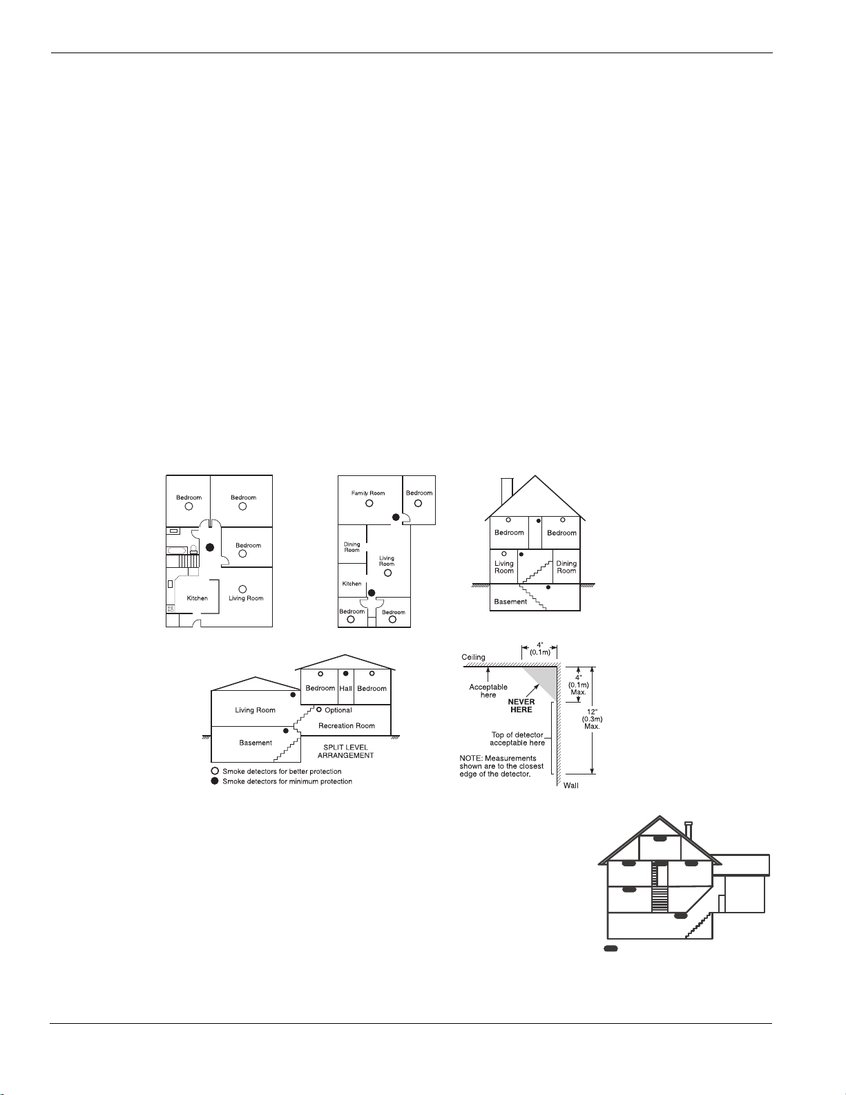
Guidelines for Locating Smoke Detectors and CO Detectors
The following information is for general guidance only and it is recommended that local fire codes and regulations be consulted when locating
and installing smoke and carbon monoxide alarms.
Smoke Detectors
Research indicates that all hostile fires in homes generate smoke to a greater or lesser extent. Detectable quantities of smoke precede detectable
levels of heat in most cases. Smoke alarms should be installed outside of each sleeping area and on each level of the home.
DSC recommends that additional smoke alarms beyond those required for minimum protection be installed. Additional areas that should be
protected include: the basement; bedrooms, especially where smokers sleep; dining rooms; furnace and utility rooms; and any hallways not
protected by the required units.
On smooth ceilings, detectors may be spaced 9.1m (30 feet) apart as a guide. Other spacing may be required depending on ceiling height, air
movement, the presence of joists, uninsulated ceilings, etc. Consult National Fire Alarm Code NFPA 72, CAN/ULC-S553-02 or other appropriate national standards for installation recommendations.
• Do not locate smoke detectors at the top of peaked or gabled ceilings; dead air space in these locations may prevent smoke detection.
• Avoid areas with turbulent air flow, such as near doors, fans or windows. Rapid air movement around the detector may prevent smoke from
entering the unit.
• Do not locate detectors in areas of high humidity.
• Do not locate detectors in areas where the temperature rises above 38
• Smoke detectors should always be installed in USA in accordance with Chapter 11 of NFPA 72, the National Fire Alarm Code: 11.5.1.1. :
Where required by applicable laws, codes, or standards for a specific type of occupancy, approved single- and multiple-station smoke alarms
shall be installed as follows:
(1) In all sleeping rooms and guest rooms.
2) Outside of each separate dwelling unit sleeping area, within 6.4 m (21 ft) of any door to a sleeping room, the distance measured along a path of travel.
(
(3) On every level of a dwelling unit, including basements.
(4) On every level of a residential board and care occupancy (small facility), including basements and excluding crawl spaces and unfinished attics.
(5) In the living area(s) of a guest suite.
(6) In the living area(s) of a residential board and care occupancy (small facility).
oC
(100oF) or falls below 5oC (41oF).
Figure 1
CO Detectors
Carbon monoxide gas moves freely in the air. The human body is most vulnerable to the effects of CO gas
during sleeping hours. For maximum protection, a CO alarm should be located outside primary sleeping
areas or on each level of your home. Figure 5 indicates the suggested locations in the home. The electronic sensor detects carbon monoxide, measures the concentration and sounds a loud alarm before a
potentially harmful level is reached.
Do NOT place the CO alarm in the following areas:
• Where the temperature may drop below -10ºC or exceed 40 ºC.
• Near paint thinner fumes.
• Within 5 feet (1.5 meters) of open flame appliances such as furnaces, stoves and fireplaces.
• In exhaust streams from gas engines, vents, flues or chimneys.
• In close proximity to an automobile exhaust pipe; this will damage the detector.
BEDR OOM
BEDROOM
GROUND
FLOOR
CARBON M ONOXIDE DETEC TOR
BEDROOM
KITCHE N
BASEM ENT
Figure 5
GARAGE
ii
Page 4
Chapter 1 Installation & Wiring
Chapter 1 Installation & Wiring
This Installation Guide provides the basic installation, wiring and programming information required to program the PowerSeries PC1616,
PC1832, and PC1864 control panels.
All necessary information required to meet UL Listing requirements is included in this document.
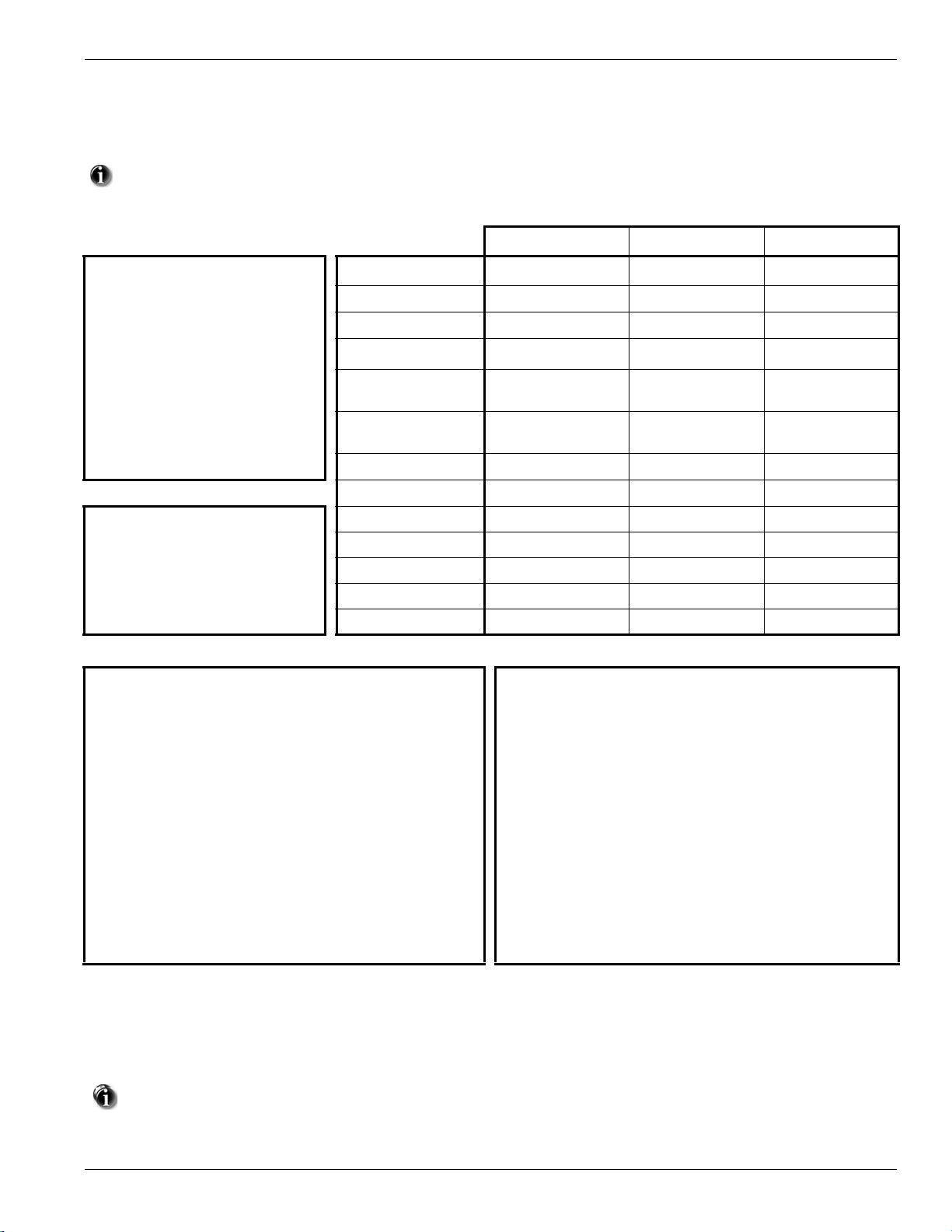
Technical Summary
FEATURES
PC1616 PC1832 PC1864
OUT Of THE BOX
Qty 1
Qty 1
Qty 1
Qty 1
Qty 2
Qty 1
Qty 5
Qty 16
Qty 1
Qty 1
Qty 1
Cabinet
PC Module
Installation Guide
User Manual
Cabinet Label
Cabinet Door Plug
Standoffs
5.6K Resistors
2.2K Resistor
1.0K Resistor
Grounding Kit
On-board Zones 6 8 8
Hardwired Zones 16 (1xPC5108) 32(3xPC5108) 64 (7xPC5108)
Wireless Zones 32 32 64
Keypad Zone Support
On-board PGM
Outputs
PGM Expansion
Keypads 8 8 8
Partitions 2 4 8
SPECIFICATIONS
Temp Range . . . 0°C-49°C (32°F-120°F)
Humidity (Max) . . . . . . . . . . . . .93%R.H.
Power Supply . . 16.5VAC/40VA @60Hz
Current Draw (Panel) . . . .110mA (nom.)
Aux+ Output . . . . 11.1-12.6VDC/700mA
Bell Output. . . . . . 11.1-12.6VDC/700mA
User Codes 47 + Master Code 71 + Master Code 94 + Master Code
Event Buffer 500 Events 500 Events 500 Events
Transformer Required 16.5VAC/40VA 16.5VAC/40VA 16.5VAC/40VA
Battery Required 4Ah / 7Ah/14AHr 4Ah / 7Ah/14AHr 4Ah / 7Ah/14AHr
Bell Output 12V/700 mA (cont) 12V/700 mA (cont) 12V/700 mA (cont)
COMPATIBLE DEVICES
Keypads
PK55XX Keypad.............................................................. 125mA (max.)
RFK55XX Keypad ...........................................................135mA (max.)
LCD5511 Fixed Message LCD Keypad ........................... 85mA (max.)
LED5511Z 8-zone LED Keypad .....................................100mA (max.)
(Backward compatible with all PowerSeries keypads) Modules
Cabinets
PC5003C......................................... 222x298x78mm (11.3x11.7x3.0in)
PC500C (residential burg only) .........213x235x78mm (8.4x9.25x3.0in)
PC4050CAR (UL commercial burg
CMC-1 (UL commercial burg) ......... 287x297x76mm (11.3x11.7x3.0in)
Suttle, SAE 14 ......................... 355.6 x 362x 95mm (14x14.25x 3.75in)
Suttle, SAE 21 ......................... 533.4 x 362x 95mm (21x14.25x 3.75in)
Suttle, SAE 28 ......................... 711.2 x 362x 95mm (28x14.25x 3.75in)
Suttle, SAE 42 ....................... 1066.8 x 362x 95mm (42x14.25x 3.75in)
).. 305x 376x124mm (12.0x14.8x4.9in)
PGM 1 - 50mA
PGM 2 - 300mA
8x50mA (PC5208)
4x500 mA (PC5204)
TL-250/TL300 Communicator ............................................ 275/350mA
GS2060/GS2065 (GPRS/GSM only)........................................... 65mA
GS2060-SM (GPRS only) ...........................................................90mA
TL260GS/TL265GS (Ethernet/GPRS) ......................................100mA
TL260-SM (Ethernet only) ......................................................... 100mA
TL260GS-SM (Ethernet/GPRS only)......................................... 120mA
PC5100 2-wire Interface............... 40mA plus devices to 170mA max.
RF5132-433 Wireless Receiver ...............................................125mA
RF5108-433 Wireless Receiver ...............................................125mA
PC5108 Zone Expander ............................................................. 30mA
PC5200 Power Supply ................................................................20mA
PC5204 Power Supply with 4 Programmable Outputs................ 30mA
PC5208 Low Current Programmable Output Module ................. 50mA
Escort5580 Telephone Interface Module ................................... 130m
PGM 1 - 50mA
PGM 2 - 300mA
8x50mA (PC5208)
4x500 mA (PC5204)
PGM 1, 3, 4 - 50mA
PGM 2 - 300mA
8x50mA (PC5208)
4x500 mA (PC5204)
*The T-Link TL-150 is not UL/ULC listed
Classified in Accordance with ANSI/SIA CP-01-2000 (SIA-FAR)
INSTALLATION
Begin the installation by mounting additional modules in the cabinet using the stand-offs provided, then mount the cabinet in a dry, protected
area with access to unswitched AC power. Install hardware in the sequence indicated in the following pages. Do NOT apply power until installation is complete.
All wiring entry points are designated by arrows. All circuits are classified UL power limited except for the battery leads. Minimum 1/4”
(6.4mm) separation must be maintained at all points between power limited and non-power limited wiring and connections.
1
Page 5
PowerSeries - PC1616/PC1832/PC1864
PC Boar d
Cabinet
Stand Of f
Pr imar y:120V A C/60Hz.
Secondar y: 16.5VAC 40VA
DSCPTD 1640U
Class II Tr ansf or mer
NO TE: Do not connect
transf or mer to receptacle
controlled by a s witch
Incorrect connections may result in PTC failure or improper operation.
Inspect wiring and ensure connections are correct be fo re appl ying po we r.
W ARNING:
Incorrect connection of batteries ma y result in batter y rupture or Fire Hazar d.
Do NO T allo w metal objects to connect the Positive and Negative Terminals.
Ensure that batteries are connected with correct polarity [Red to (+), Blac k to (-)].
F ailure to compl y with this ma y result in batte ry rupture and/or Fire Hazar d.
All cir cuits are c lassified fo r UL Installations as Po wer Limited/Class II Power Limited
e xcept fo r battery leads which are not po wer limited.
Do NO T r oute an y wiring o ver cir cuit boar ds .M aintain at least 1"(25.4mm) separation.
A minim um of 1/4" (6.4mm) separation mu st be maintained at all points between
po wer limited wiring and all other non-po wer limited wiring.
1. Inser t Stand off into cabinet
mounting hole in the
desired location. Snap-inplace .
2. P osition circuit board
mounting holes ov er
standoffs . Press fir mly
on board to snap-in-place .
IMPOR T ANT :
a)This equipment, Alar m Controller PC1616/1832/1864 shal l
be installed and used within an en vironment that pr ov ides th e
pollution degree max 2 and ov er vo ltages categor y II
NON-HAZARDOUS LOCA TIONS , indoor onl y. The equipment is
FIXED and PERMANENTL Y connected and is designed to be
installed by ser vice persons only; [ser vice person is defined as a
person ha ving the appropr iate technical training and e xper ience
necessar y to be aw are of hazards to which that person ma y be
e xposed in per fo rm ing a task and of measures to minimi ze the ri sks
to that person or other persons .]
b)The connection to the mains supply must be made as per the local
author ities ru les and regulations.
An appropr iate disconnect de vice must be pr ov ided as par t of th e
bu ilding installation. Where it is not possi bl e to rely on identification of
the neutral in the AC Mains supply the disconnecting device must
disconnect both poles simultaneously (line and neutral). The device
shall disconnect the supply during servicing.
c)The equipment enclosure must be secured to the bu ilding str uctur e
bef ore operation.
e)Inter nal wi ri ng must be routed in a manner that pr ev ents:
- Excessi ve strain on wire and on te rm inal connections;
- Loosening of te rm inal; connections;
- Damage of conductor insulatio n
f) Disposal of the used batte ri es
shall be made according to the w ast e
reco ve ry and recycling regulations applicab le to the intended mar k et.
CON1
BA T+BA T-
FUSE
AC AC
16.5V /40V A
AC
To EGND
Te r m inal
230 V /50 Hz International
AC
CON1
BA T+BA T-
PO WER LIMITED
NON-PO WER LIMITED
DSC Model BD7-12
or equiv alent
Batter y
Standb yTime:
24H rs min.
BLA CK
RE D
TB-2
AC AC RED BL KY EL GRN Z1 COM Z2 Z3 COM Z4 Z5 COM Z6 Z7 COM Z8
AU X+ BELL +
AU X- BELL-
PGM1 PGM3
EGND
TI PT -1
PGM2 PGM4
RING R- 1
DSC
220 220
UA 50 3
Cab le Tie (not supplied) recommended
PC1864
On ly
PC1864
PC1832
On ly
PC1616/1832/1864
High V oltage .D isconnect AC Po wer
and telephone lines bef ore servicing
W ARNING:
High V oltage . Disconnect AC Po wer
and telephone lines bef ore servicing
W ARNING:
TB-2
DSC
REV XX
220 220
U A503
CON1
BA T+BA T-
PC-LIN K
Internally Connected
AUX+ and Keybus (Red) are Internally Connected
To ta l current draw from Keyp ads, PG MO utput s and
Aux circuit sm ust not exceed 700m A
PC1864
On ly
PC1864
PC1832
Onl y
PC1616/1832/1864
10
12V / 7 AHr 12V / 7 AHr
Nor th America Onl y
See ground wiring
diagram in the Installation
section of this manual
DG009606
Keybus
PGMs
Zones
Telephone
AC AC + AUX - + BELL -
RED BLK YEL GRN
Z1 COM Z2 Z3 COM Z4 Z5 COM Z6 Z7 COM Z8
EGND
RING TIP R-1 T-1
1 PGM 2 3 PGM 4
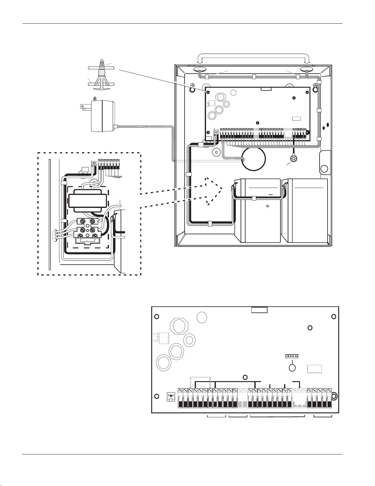
PC1616/1832/1864 Wiring Diagram
2
Page 6
Chapter 1 Installation & Wiring
CONTROL
PANEL
150’ (46m)
150’ (46m)
500’ (152m)
500’ (152m)
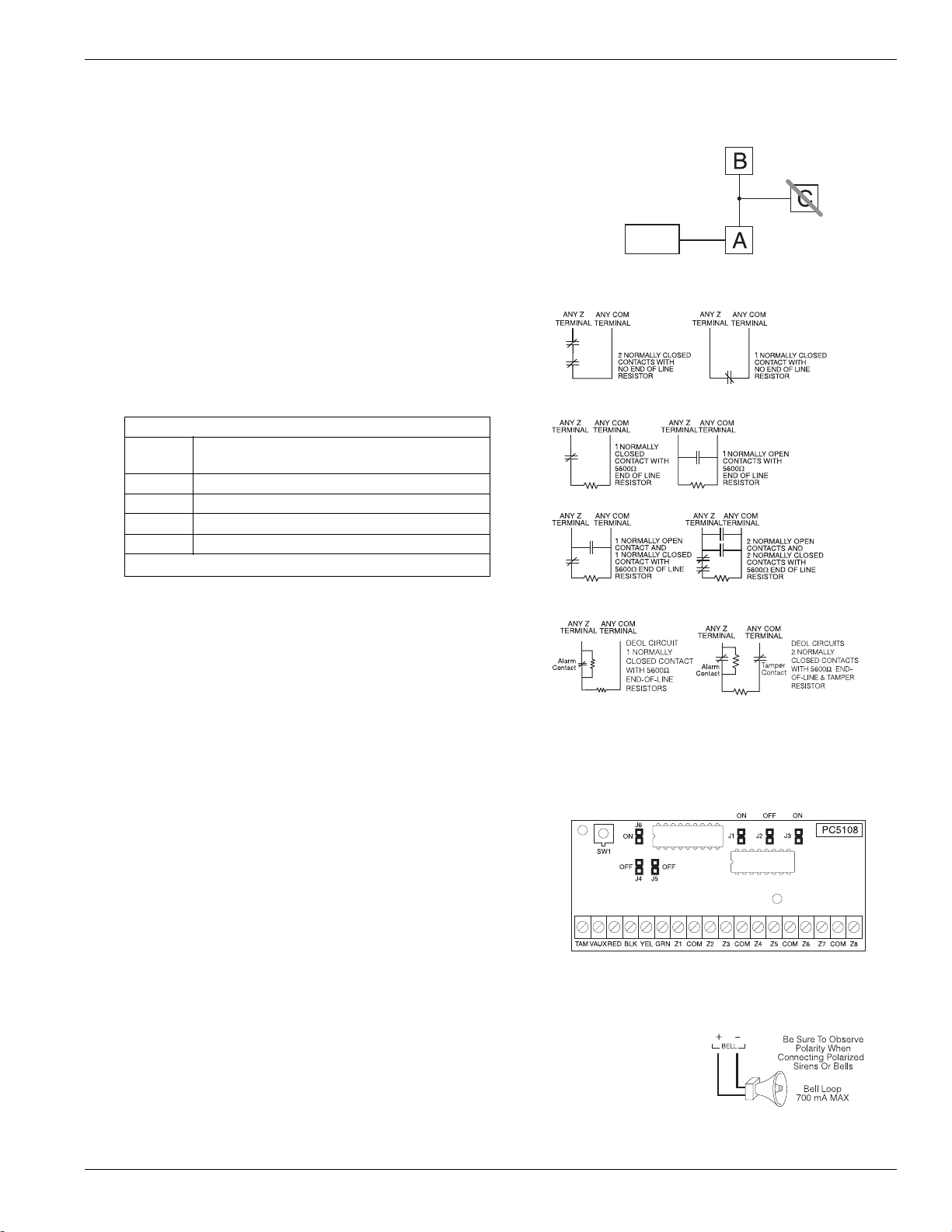
Burglary Zone Wiring Chart
Wire
Gauge
Maximum Wire Length to
End-of-Line Resistor (ft/meters)
22 3000 / 914
20 4900 / 1493
19 6200 / 1889
18 7800 / 2377
Figures are based on maximum wiring resistance of 100
Normally Closed Loops - Do NOT use for UL Installations
Single End-of-Line Resistor Wiring
Double End-of-Line Resistor Wiring
1.1 Keybus Wiring
The 4-wire KEYBUS (red, black, yellow and green) is the communication connection between the control panel and all modules. The 4 KEYBUS terminals of all modules must be connected to the 4 KEYBUS terminals of the main control panel.
The following rules must be followed when wiring the Keybus:
• Minimum 22 AWG wire, max. 18 AWG (2-wire twisted preferred)
• Do not use shielded wire
• Modules can be home run, connected in series or T-tapped, provided that
the maximum wire distance from the control panel to any module does not
exceed 1,000 feet (305m)
• No more than 3,000 feet (915m) of wire can be used in total
1.2 Zone Wiring
Zones can be wired for Normally Open or Normally Closed contacts, with
Single-End-of-Line (SEOL) or Double End-of-Line (DEOL) resistors.
Observe the following guidelines:
• For UL Listed Installations use SEOL or DEOL only.
• Minimum 22 AWG wire, maximum 18 AWG
•Do not use shielded wire
Wire run resistance shall not exceed 100Refer to the chart below:
•
• [001]-[004] Selects Zone Definition
• [013] Opt [1] Selects Normally Closed or EOL resistors
• [013] Opt [2] Selects SEOL or DEOL resistors
• [101]-[108] Opt [14], [15], [16] Selects Normally Closed SEOL or DEOL
for on-board zones (PC1832/1864, Zone 1-8; PC1616, Zones 1-6)
Zone Status - Loop Resistance/Loop Status
• Fault - 0 (shorted wire/loop)
• Secure - 5600 (contact closed)
1.3 Zone Expanders
Zone expanders add zones in groups
of eight to the Alarm system. Module
jumpers J1, J2, J3 are required to
assign zones to these modules.
Jumper settings for PC5108 v2 are
shown here.
• PC5108 v1.0 supports first 32
zones only.
• PC5700 enrolls as two modules
• Do NOT use PC5108 v1 and
PC5108 v2 on the same panel.
Module Zones
Jumpers Assigned
J1 J2 J3
ON ON ON Zones Disabled
OFF ON ON Zones 09-16
ON OFF ON Zones 17-24
OFF OFF ON Zones 25-32
ON ON OFF Zones 33-40
OFF ON OFF Zones 41-48
ON OFF OFF Zones 49-56
OFF OFF OFF Zones 57-64
1.4 Bell Wiring
These terminals supply 700mA of current at 12VDC for commercial installations and 11.1-12.6VDC for
residential installations (e.g. DSC SD-15 WULF). To comply with NFPA 72 Temporal Three Pattern
requirements: Program [013] Opt [8] ON. Note that Steady, Pulsed alarms are also supported.
The Bell output is supervised and power limited by 2A PTC. If unused, connect a 1000 resistor across
Bell+ and Bell- to prevent the panel from displaying a trouble. See [][2].
• Tamper - infinite (broken wire, open)
• Violated - 11,200 (contact open)
Refer to the associated installation sheet for Jumper locations
for the PC5108 v1 and PC5700.
3
Page 7
PowerSeries - PC1616/PC1832/PC1864
RM-1/RM-2 POWER LOOP
SUPERVISORY RELAY
EOLR-2
END-OF-LINE
RESISTOR
5600 Ohm, 0.5W
2200 Ohm
END-OF-LINE
RESISTOR
EOLR-3
ALARM
INITIATING
LOOP
RESISTANCE
100 Ohm
12V
DC
CO DETECTOR
RM-1/RM-2
POWER LOOP
SUPERVISORY
RELAY
(12V
DC, 35mA)
ALARM
INITIATING
LOOP
RESISTANCE
100 ohm
SEOL
RESISTOR
(5600 ohm)
PC1616/1832/1864
ANY
COM
ZONE
INPUT
POWER ALARM TROUBLE
NC C NO NC C NO
ANY
Z
(SEOL TYPE 41)
AUX
+
+
-
-
+
-
DG009477
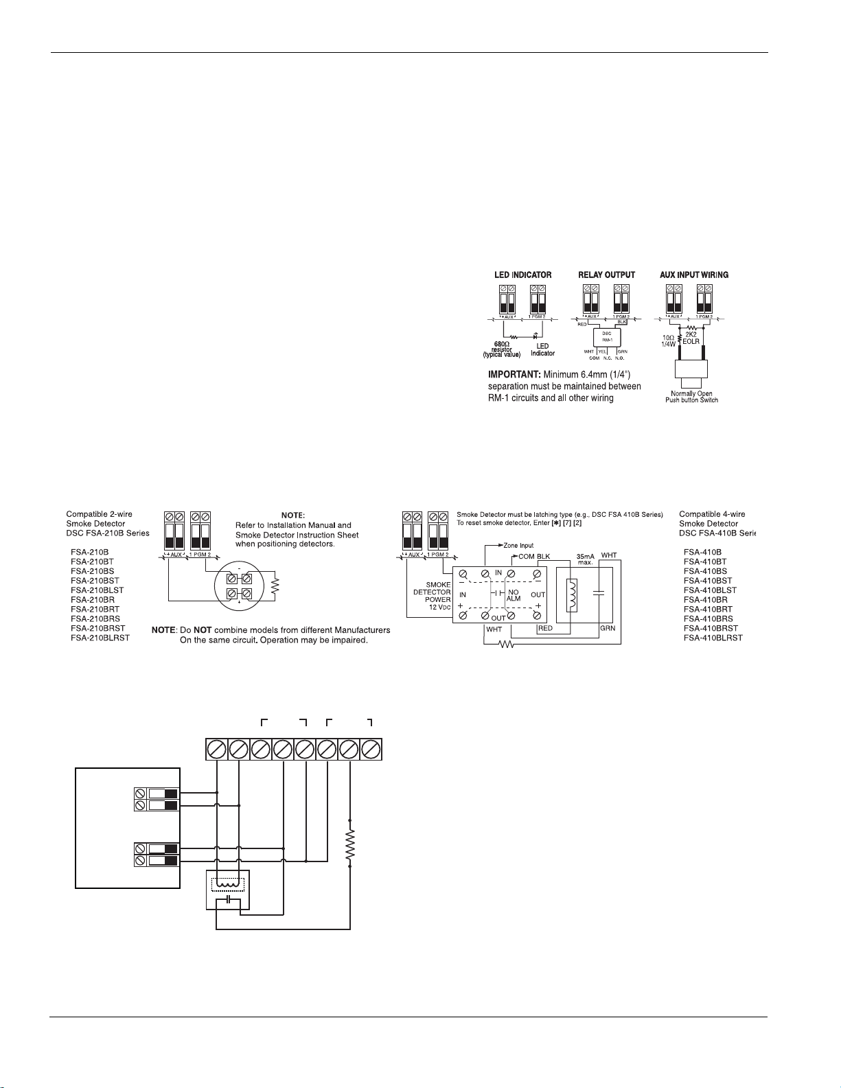
The following hardwired CO Detector models can be used
with PC1616/PC1832/PC1864 v4.5 (and higher) control
panels:
• Potter Model CO-12/24, UL File E321434
• Quantum Model 12-24SIR, UL File E186246
• NAPCO Model FW-CO12 or FW-CO1224, UL File E306780
• System Sensor Model CO1224, UL File E307195
NOTE: For multiple unit connections, the leads between CO detectors need to be broken. The power supervision relay has to be powered from the last detector in the loop.
Wireless CO detectors are also available. When installing
wireless CO detectors, use only DSC model WS4913. A DSC
wireless receiver model RF5132-433 v5.1 (and higher) or DSC
keypad receiver models RFK55XX-433 (xx= 00/01/08/16/64)
v1.2 (and higher) are required when installing wireless CO
detectors. For more details on either the WS4913 CO detector
or the receivers, please refer to their respective installation
manuals.
1.5 AUX Power Wiring
The control panel can provide a maximum of 700mA of current for modules, powered detectors, relays, LEDs, etc. If the total current required
exceeds 700mA an additional power supply is required (e.g., PC5200, PC5204). See list below.
Min/max operating voltages for devices, sensors and modules is 9.5V
DC - 14VDC.
1.6 PGM Wiring
PGMs switch to ground when activated from the control panel. Connect the
positive side of the device to be activated to the AUX+ Terminal. Connect the
negative terminal to the PGM.
Current output is as follows:
• PGM 1, 3, 4 50mA
• PGM 2 300mA
2-Wire Smoke Detectors Initiating Circuit
• Style B (Class B), Supervised, Power Limited
• UL Compatibility Identifier. . . . . . . . . . . . . . . . . . . . . . . . . . . . . . . PC18-1
• DC Output Voltage . . . . . . . . . . . . . . . . . . . . . . . . . . . . . . . . 9.8-13.8 VDC
• Detector Load . . . . . . . . . . . . . . . . . . . . . . . . . . . . . . . . . . . . .2mA (MAX)
• Single End-of-Line (SEOL) Resistor. . . . . . . . . . . . . . . . . . . . . . . . .2200
• Loop Resistance. . . . . . . . . . . . . . . . . . . . . . . . . . . . . . . . . . . . 24(MAX)
• Standby Impedance . . . . . . . . . . . . . . . . . . . . . . . . . . . . . . . 1020
• Alarm Impedance. . . . . . . . . . . . . . . . . . . . . . . . . . . . . . . . . . 570(MAX)
• Alarm Current . . . . . . . . . . . . . . . . . . . . . . . . . . . . . . . . . . . .89mA (MAX)
For current levels greater than 300mA, a relay is required.
PGM2 can also be used for 2-wire smoke detectors.
NOTE: Use SEOL resistors on fire zones only.
LED output with current limiting resistor and optional relay
driver output
UL Compatibility ID For FSA-210B Series is: FS200
NOTE: For ULC Listed installations use FSA-210A and FSA-410A series.
1.7 Carbon Monoxide Detector Wiring
4-Wire Smoke Detectors
4
Page 8
1.8 Telephone Line Wiring
T-1
R-1
TIP
RING
RJ-31X
RED
GRN
BRN
GRA
Tighten nut to break paint and make
good connection to the cabinet
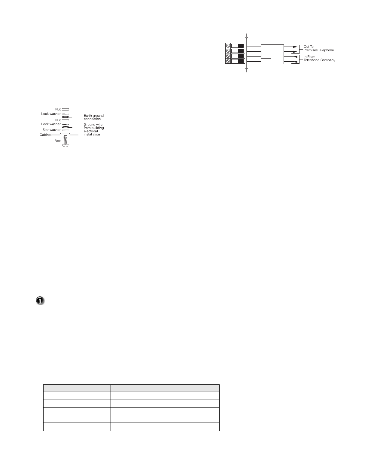
Wire the telephone connection terminals (TIP, Ring, T-1, R-1) to an RJ-31x
Connector as indicated. For connection of multiple devices to the telephone
line, wire in the sequence indicated. Use 26 AWG wire minimum for wiring.
Telephone format is programmed in option [350].
Telephone Call Directions are programmed in options [351]-[376].
1.9 Ground
Ground Installation
1.10 Battery
Standby Battery Guide
Battery Charging Current: 400 mA
Battery Standby
Size 4Hr 24Hr
---------------------------------------------------------
4Ahr 700mA --- 7Ahr 700mA 180mA
14Ahr 700mA 470mA
NOTE: Battery capacity will deteriorate with age and the number of
charge/discharge cycles. Replace
every 3-5 years.
A sealed, rechargeable, lead acid battery or gel type battery is required to
meet UL requirements for power standby times.
NOTE: UL Residential/Commercial Burglary installations require 4Hrs
of standby battery time.
NOTE: UL/ULC Residential Fire & Health Care installations require 24
Hrs of standby battery time. ULC Commercial Burglary and Fire monitoring installations require 24Hrs of standby battery time plus 5 minutes
of alarm condition.
1.11 AC Wiring
AC Wiring (UL Listed Installations)
Primary: 120VAC/60Hz./0.33A
Secondary: 16.5VAC/40VA DSC PTD1640U, DSC PTC1640U,
DSC PTD1640U-CC Plug-in, Class 2 Transformer.
NOTE: Use DSC PTD1640 for Canadian installations.
Chapter 1 Installation & Wiring
For UL Listed installations, do NOT connect transformer to a receptacle controlled by a switch.
1.12 RFK5500 and RFK5564 Easy Wireless Enrollment Procedure
1. Enter [ ✱ ][8][Installer Code][898]. The LCD displays the following: “Wireless Enrollment Mode.”
2. Place the wireless device in the desired location.
3. Activate the device as described in the associated installation sheet. The electronic serial number (ESN) is displayed.
4. Press [
5. Enter a zone number (01-64) then press [
6. After successful entry of the zone number, the system prompts for the zone type. (The recommended zone type is displayed). Press [
✱ ] to confirm the ESN. If the serial number is incorrect, press [#] to discard it, and repeat this step. After successful confirmation of
the serial number, the system prompts for the zone number. The next available zone is displayed.
NOTE: Only one device may be enrolled in each zone. If a zone already has a device enrolled, press [*] to overwrite the zone or [#] to enter
another zone number.
accept the zone type or enter:
Device Type Zone Definition
2 Door/Window Contact [01] Delay 1
3 PIR or Glassbreak [05] Interior, Stay-Away
4 Smoke Detector [88] Standard 24 Hr Fire (Wireless)
5 Pendant [16] 24 Hour Panic
8 CO Detector [81] 24 Hour CO Detection
✱ ] to accept. The next available zone is preloaded.
✱ ] to
5
Page 9

PowerSeries - PC1616/PC1832/PC1864
Chapter 2 User Commands
Any system keypad can be used to program or perform any keypad command. LED keypads use status and zone indicator lights to represent
alarm functions and status. The LCD keypad displays the description and status indicator lights represent alarm functions and status. This section
describes basic keypad commands.
Press the [#] key to reset the keypad if an error has been made entering user codes or keypad commands.
2.1 Away Arming
The Ready light must be ON to arm the system. If the Ready light is OFF, ensure that all protected doors and windows are secure or
bypassed. To arm the system in the Away mode, either press and hold the Away function button for 2 seconds or enter a valid user code and
leave the premises through a door programmed as Delay. Upon arming, the Armed light will turn ON. If a user code was used to arm the system and Stay/Away zones are programmed, the Bypass light will turn ON and will turn OFF when a door programmed as Delay is violated.
If the Audible Exit Delay option is enabled, the keypad will beep once every second during the exit delay (and three times a second during
the last 10 seconds) to prompt the user to leave.
2.2 Stay Arming
The Ready light must be ON to arm the system. If the Ready light is OFF, ensure that all protected doors and windows are secure or
bypassed. To arm the system in the Stay mode, either press and hold the Stay function button for 2 seconds or enter a valid user code and stay
within the premises (do NOT violate a door programmed as Delay). Upon arming, the Armed light and Bypass light will turn ON. If the Stay
function button is used, the keypad will not beep during the exit delay. If a user code was used, the keypad will beep if the Audible Exit
Delay option is enabled.
2.3 Disarming
The user must enter through a door programmed as Delay. Upon entering, the keypad will emit a steady tone (and emit a pulsing tone during
the last 10 seconds of entry delay) to prompt the user to disarm the system. Enter a valid user code to disarm the system. If an alarm occurred
while the panel was armed, the Memory light and the zones that went into alarm will be flashing (LED keypad) or the keypad will display
‘Alarm in Memory’ (LCD keypad). Press the [#] key to return the keypad to the Ready state.
2.4 [] Commands
The following is a list of the [] commands available and a description of each:
[][1] Bypass (disarmed state)/Reactivate Stay/Away Zones (armed state)
[][2] Display Trouble Conditions
[][3] Display Alarm Memory
[][4] Door Chime Enable/Disable
[][5] User Code Programming
[][6] User Commands
[][7][x] Command Functions 1 – 4
[][8] Installer Programming
[][9][code] No-Entry Arming
[][0] Quick Arm (disarmed state)/Quick Exit (armed state)
[][1] Bypass/Re-activate Stay/Away Zones
LED Keypad
Press [][1] to enter the bypass mode. If the Code Required for the Bypass option is enabled, enter a valid user code. The Bypass light will
flash. The keypad will turn ON the corresponding zone light to indicate a zone is bypassed. To bypass or unbypass a zone, enter the 2-digit
zone number. Once the correct zones are bypassed, press [#] to exit. The Bypass light will be ON if any zones are manually bypassed.
LCD Keypad
Press [][1] to enter the bypass mode. If the Code Required for the Bypass option is enabled, enter a valid user code. The keypad will display ‘Scroll to View Zones’. The keypad will display the programmed zone labels for the zones and include the letter ‘O’ in the bottom right
corner if the zone is violated, or the letter ‘B’ if the zone is bypassed. Scroll to the appropriate zone and press the [] key to change the
bypass status (or enter the 2-digit zone number). Once the correct zones are bypassed, press [#] to exit.
Additional Bypass Commands:
Bypass Recall: Press [99]. The keypad will recall the last group of zones that were bypassed
Clear Bypass: Press [00]. The keypad will clear the bypass on all zones.
Save Bypass: Press [95]. The keypad will save which zones are manually bypassed.
Recall Save: Press [91]. The keypad will recall the bypassed zones that were saved.
Hold-up Zones cannot be assigned to bypass groups.
Re-activate Stay/Away Zones: Press [][1] when the system is armed in the Stay mode to change the armed status to Away mode. The
system will add the Stay/Away zones back into the system after the exit delay time expires.
6
Page 10
Chapter 2 User Commands
[][2] Trouble Display
Refer to Appendix D – Troubleshooting Guide, for troubleshooting assistance and a detailed description of all trouble conditions.
When powering up the system for the first time, or in the event of a loss of power (including battery removal), a Loss of Clock trouble will
appear on the display. Press [8] on any keypad or [
] on any PK series keypad to access the time and date programming menu.
[][3] Alarm Memory Display
The Memory light will be ON if an alarm occurred during the last armed period. Press [][3]. The Memory light will flash and the keypad
will display the zones that went into alarm.
To clear the Memory light, arm then disarm the system.
[][4] Door Chime Enable/Disable
Press [][4]. The keypad will emit 3 rapid beeps if the door chime feature is now enabled and a steady 2-second tone if it is now disabled.
The same function can be performed by pressing and holding the Chime function button for 2 seconds.
[][5] Program User Codes
The following table identifies available user codes:
Code Type Function
[01]-[39], [41]-[95] General User Codes Arm, disarm
[40] Master Code All functions
Programming User Codes:
LED Keypad:
Press [][5] followed by the Master Code. The Program light will flash. The keypad will turn ON the corresponding zone lights to indicate if
any user codes are programmed. To add or change a user code, enter the 2-digit user code to be programmed. The zone light will flash. Enter
a new 4 or 6-digit user code or press [
the user code will stop flashing. To add or change another user code, enter the 2-digit user code to be programmed or press [#] to exit.
LCD Keypad:
Press [][5] followed by the Master Code. The keypad will display the first user (user 01) and include the letter ‘P’ in the bottom, right corner if the user code is programmed. Scroll to the appropriate user and press the [] key to program the user (or enter the 2-digit user num-
ber). Enter a new 4 or 6-digit user code or press [] to delete the user code. After the user code is programmed or deleted, scroll to another
user or press [#] to exit.
] to delete the user code. After the user code is programmed or deleted, the zone light corresponding to
Programming Partition Assignment:
Press [][5] followed by the Master Code or Supervisor Code. Press [98] followed by the 2-digit user to change to the partition assignment.
The keypad will turn ON the corresponding zone light to indicate which partition(s) the user is assigned to. For example, if zone light 1 is
ON, the user is assigned to partition 1. To change the partition assignment, press the number corresponding to the partition. Once the correct
partitions are assigned to the user, press [#] to exit. To change the partition assignment for another user, press [98] followed by the 2-digit
user number. When finished, press [#] to exit.
Programming User Attributes:
Press [][5] followed by the Master Code or Supervisor Code. Press [99] followed by the 2-digit user to change to the user attributes. The
keypad will turn ON the corresponding zone light to indicate which attributes are assigned to the user.
Light [1] User can enter User Code Programming section with this code
Light [2] Duress Reporting Code is sent whenever this code is entered
Light [3] User can manually bypass zones
Light [4] User can access the Escort5580 module remotely
Light [5] For Future Use
Light [6] For Future Use
Light [7] The panel will squawk when the user arms/disarms
Light [8] One-time use code – Can disarm the system once per day and is reset at midnight.
To change the user attributes, press the number corresponding to the attribute. Once the correct attributes are assigned to the user, press [
exit. To change the user attributes for another user, press [99] followed by the 2-digit user number. When finished, press [
#] to exit.
#] to
7
Page 11

PowerSeries - PC1616/PC1832/PC1864
[][6] User Functions
Press [][6] followed by the Master Code, then press the number corresponding to the following functions:
[1]
[2]
[3]
[4]
[5]
[6]
[7] -[8]
Program Time and Date:
twenty-four-hour system (e.g., 8:00 PM = 2000 hours).
Auto-arm/Auto-disarm Enable/Disable:
steady 2-second tone if it is now disabled.
Auto-arm Time/Day:
time (HH:MM). Program the time using the twenty-four-hour system (e.g., 8:00 PM = 2000 hours).
System Test:
test the backup battery and transmit a reporting code to the central station (if programmed).
Enable DLS: The panel will temporarily enable DLS for 1 or 6 hours depending on programming (see Sect [702] opt.[7]).
User Initiated DLS:
For Future Use
The panel will perform the following: activate the bell output, keypad buzzer and all keypad status lights for 2 seconds,
If using LCD keypads, scroll to the desired option then press [].
Enter the time and date using the following format [HH:MM] [MM/DD/YY]. Program the time using the
The keypad will emit 3 rapid beeps if the Auto-arm/Auto-disarm feature is now enabled and a
Press the number corresponding to the day of the week (1=Sunday, 2=Monday etc.) followed by the auto- arm
The panel will attempt to call the DLS computer.
Additional Alphanumeric Keypad Functions:
When scrolling through the list of available functions, the following additional functions are available:
Event Buffer: Used to view the 500-event panel log
Brightness Control: Used to adjust the display backlighting level for optimal viewing
Contrast Control: Used to adjust the display contrast level for optimal viewing
Buzzer Control: Used to adjust the keypad buzzer tone for optimal sound
[][7][x] Command Output (1-4)
Press [][7][x]. If the Command Output Code Required option is enabled, enter a valid user code. The panel will activate any PGM output
assigned to the command output.
[][8] Installer Programming
Press [][8] followed by the Installer Code to enter Installer Programming. Refer to the ‘How to Program’ section for more information.
[][9][User Code] No-Entry Arming
Press [][9] followed by a valid user code. The system will arm in the Stay mode, and after the exit delay expires, it will remove entry delay.
All zones programmed as Delay will function like Instant zones. The system will flash the Armed light to indicate that the system is armed
with no entry delay.
[][0] Quick Arm/Quick Exit
Quick Arm: When disarmed, press [][0] to arm the system. The system will arm as if a valid user code was entered.
Quick Exit: When armed, press [][0] to activate Quick Exit. The system will allow a single zone programmed as Delay to be violated a
single time during the following 2-minute time period without changing the status of the system.
2.5 Function Keys
Keypads have 5 programmable one-touch function buttons located in a column down the right side of the keypad. These buttons can also be
activated by pressing and holding numbers [1] through [5] respectively for 2 seconds. The default for these function buttons on the PK series
keypads are as follows:
[1] Stay Arm
[2] Away Arm
[3] Chime Enable/Disable
[4] Fire Reset – Command Output 2
[5] Quick Exit
8
Page 12
Chapter 3 Programming
Chapter 3 Programming
This chapter provides the information necessary to program all the features required for a basic system, as well as common applications.
3.1 Template Programming
Selecting [][8] [Installer Code] [899] displays the current 5-digit template programming code. Refer to Appendix E - Template Programming for
a detailed description of available templates and corresponding 5-digit codes. After entering a valid 5-digit template programming code, you will
be prompted to enter the following in the sequence indicated below:
This feature requires a PK55xx or RFK55xx series keypad, v.1.1 or higher.
1. Central Station Telephone Number, enter 32-Character Telephone number
Program the required Central Station phone number. Press [#] to complete your entry if less than 32 digits. This phone number will be
entered into the programming option [301].
2. Central Station Account Code, enter 6-digit code
Program the required Central Station Account Code. Press [#] to complete your entry if less than 6 digits. This account code will be entered
into the programming option [310].
3. Partition Account Code, enter 4-digit code
This programming section will only be prompted if Contact ID has been selected as a communications format. Program the required Partition Account Code. This Partition account code will be entered into the programming option [311].
4. DLS Access Code, enter 6-digit code
Program the required DLS Access Code. Press [#] to complete your entry if less than 6 digits. This access code will be entered into the programming option [403].
5. Partition 1 Entry Delay 1, Partition 1 Exit Delay, enter each 3-digit delay time
Program the desired 3-digit Partition 1 Entry Delay (in seconds) followed by the desired 3-digit Partition 1 Exit Delay (in seconds). These
values will be entered in [005] > [01], entries 1 and 3, respectively.
6. Installer Code
Enter the required 4- or 6-digit access code installer access code (dependent on [701], entry 5). This Installer Access Code will be entered in
[006]. After the installer code has been programmed the keypad will return to the base installer programming menu.
All template programming information must be re-entered after performing a hardware or software panel default.
3.2 DLS Programming
3.2.1 Local Programming:
Follow the steps below in the sequence indicated to set up local programming using DLS:
1. Initiate downloading using the DLS software.
2. Connect an RS-232 to PC-Link Cable between the Computer with DLS Software installed and the alarm panel to be programmed.
Connecting the DLS PC to the panel will automatically initiate the connection.
3.2.2 Remote Programming (via telephone line):
Refer to Section [401] on page 22 for details.
The panel battery voltage can be monitored with DLS software. After the panel information has uploaded,
battery voltage can be viewed in the DLS session window.
3.3 Advanced Keypad Programming
DSC recommends filling in the Programming Worksheet with the required information before programming the system. This will reduce the
time required to program and will help eliminate errors.
To enter Installer Programming press [][8][Installer Code]. The Program light will flash (programmable LCD keypad displays will change
to ‘Enter Section’). An error tone indicates the installer code entered is incorrect. Press [#] to clear any key presses and try again.
The default Installer Code is [5555].
The Armed and Ready lights indicate programming status:
Armed Light On Panel waiting for 3-digit section number
If in module programming, waiting for section # to be entered
Ready Light On Panel waiting for data to be entered
Ready Light Flashing Panel waiting for HEX data to be entered
You cannot enter Installer Programming while the system or any partition is armed or in alarm.
9
Page 13
PowerSeries - PC1616/PC1832/PC1864
3.3.1 Programming Toggle Options:
Enter the 3-digit programming section number:
• The Armed light will turn OFF and
• The Ready light will turn ON.
• The keypad will display which toggle options are ON or OFF
according to the chart.
• To toggle an option ON or OFF , press the corresponding num-
ber on the keypad. The display will change accordingly.
Keypad Type Option ON Option OFF
LED Zone Light ON Zone Light OFF
Fixed-Message LCD Indicator # ON Indicator # OFF
Programmable-Message LCD # Displayed Dash [-]
Displayed
• When all the toggle options are configured correctly, press the [#] key to exit the program section.
• The Ready light will turn OFF and the Armed light will turn ON.
3.3.2 Programming Decimal and Hexadecimal (HEX) Data:
• Enter the 3-digit programming section number.
• The Armed light will turn OFF and the Ready light will turn ON.
• Enter the data written in the boxes.
For sections that require multiple 2- or 3-digit numbers, the keypad will beep twice after each 2- or 3-digit entry and move to the next item in
the list. After the last digit in the section is entered, the keypad will beep rapidly 5 time s and exit the program section. The Ready light will
turn OFF and the Armed light will turn ON.
For sections that do not require data for every box (such as phone numbers), press the [#] key to exit the program section after entering all the
required data. The Ready light will turn OFF and the Armed light will turn ON.
At any time the [#] key can be pressed to exit any program section. All changes made up to that point will be saved.
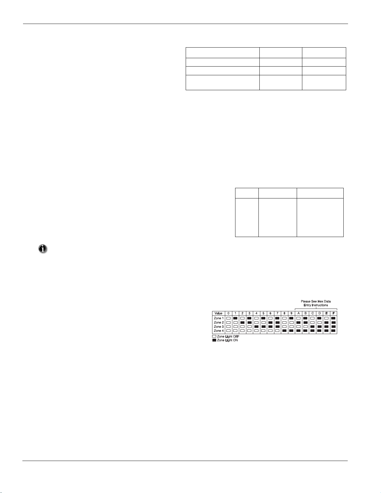
HEX (or hexadecimal) digits are sometimes required. To enter a HEX digit, press the
,] key to begin HEX programming. The Ready light will flash.
[
Refer to the following chart and press the number corresponding to the HEX digit
required. The Ready light will continue to flash. Press [
,] again to return to normal
decimal programming. The Ready light will turn ON.
Value Enter Telephone Dialer
HEX [A]
HEX [B]
HEX [C]
HEX [D]
HEX [E]
HEX [F]
Press [,][1][,]
Press [,][2][,]
Press [,][3][,]
Press [,][4][,]
Press [,][5][,]
Press [,][6][,]
Not Supported
Simulated [,] key
Simulated [#] key
Dial tone search
Two second pause
End of Number
In addition to the standard digits 0-9, HEX digits and special dialer functions can also be programmed.
3.3.3 How to Exit Installer Programming:
To exit installer programming, press the [#] key when the panel is waiting for a 3-digit section number (the Armed light is ON).
3.3.4 Viewing Programming
LED and LCD5501Z Keypads
Any programming section can be viewed from an LED or LCD5501Z
keypad. When a programming section is entered, the keypad will immediately display the first digit of information programmed in that section.
The keypad displays the information using a binary format, according to
the following chart:
Press any of the Emergency keys (Fire, Auxiliary or Panic) to advance to
the next digit.
When all the digits in a section have been viewed, the panel will exit the section. The Ready light will turn OFF, and the Armed light
will turn ON. The system is now waiting for the next 3-digit programming section number to be entered. Press the [#] key to exit the
section.
LCD Keypad
The keypad will immediately display all the information programmed when a programming section is entered. Use the arrow keys (< >) to
scroll through the data being displayed. Scroll past the end of the data displayed or press the [#] key to exit the section.
10
Page 14

Chapter 4 Programming Descriptions
Chapter 4 Programming Descriptions
The following is a brief description of the features and options available in the Power PC1616/1832/1864 control panel. Please refer to the keypad
installation sheet for function key programming.
Global Stay Arming
If enabled by the installer, when this function key is pressed the panel will prompt the user for an access code. The panel will arm all partitions
assigned to that access code in Stay Mode when exit delay expires. If a partition was armed in Away mode when the Global Stay Arming key is
pressed, that partition will switch armed status to Stay when the delay expires. The Force arm attribute must be enabled on Entry/Exit points for
this feature.
Global Away Arming
If enabled by the installer, when this function key is pressed the panel will prompt the user for an access code. The panel will arm all partitions
assigned to that access code in Away Mode when exit delay expires. If a partition was armed in Stay mode when the Global Away Arming key is
pressed, that partition will switch armed status to Away when the delay expires. The Force arm attribute must be enabled on Entry/Exit points for this
feature.
Global Disarming
If enabled by the installer, when this function key is pressed the panel will prompt the user for an access code. The panel will then disarm all partitions assigned to that access code.
[001] to [004] Zone Definitions
Option Description
[00]
Null Zone: Zone not used
[01]
Delay 1: When armed, provides entry delay when violated (follows Entry Delay 1)
[02]
Delay 2: When armed, provides entry delay when violated (follows Entry Delay 2)
[03]
Instant: When armed, instant alarm when violated
[04]
Interior
[05]
Interior Stay/Away: Similar to ‘Interior’ except that panel will auto-bypass the zone if Armed in the Stay mode
[06]
Delay Stay/Away: Similar to ‘Delay 1’ except that panel will auto-bypass the zone if Armed in the Stay mode
[07]
Delayed 24-Hour Fire (Hardwire): Instant audible alarm when violated, communication is delayed 30 seconds. If alarm is acknowl-
edged during this time (by pressing a key), the alarm will be silenced 90 seconds and will repeat the cycle. If not, alarm will latch and
communicate after a 30-second delay
[08]
Standard 24-Hour Fire (Hardwire): Instant alarm and communication when violated
[09]
24-Hr Supervision (Hardwire): Instant alarm and communication when violated. Will not sound the bell or keypad buzzer
[10]
24-Hr Supervisory Buzzer: Instant alarm, panel will activate keypad buzzer instead of bell output
[11]
24-Hr Burglary: Instant alarm when violated, audible alarm at default. Reporting code BA, BH
[12]
24-Hr Hold-up: Instant alarm when violated, silent alarm at default. Reporting code HA, HH
[13]
24-Hr Gas: Instant alarm when violated, audible alarm at default. Reporting code GA, GH
[14]
24-Hr Heat: Instant alarm when violated, audible alarm at default (also known as high-temp). Reporting code KA, KH
[15]
24-Hr Auxiliary (Medical): Instant alarm when violated, silent alarm at default. Reporting code MA, MH
[16]
24-Hr Panic: Instant alarm when violated, audible alarm at default. Reporting code PA, PH
[17]
24-Hr Emergency: Instant alarm when violated, audible alarm at default. Reporting code QA, QH
[18]
24-Hr Sprinkler: Instant alarm when violated, audible alarm at default. Reporting code SA, SH
[19]
24-hr Water: Instant alarm when violated, audible alarm at default (also known as high water level). Reporting code WA, WH
[20]
24-Hour Freeze: Instant alarm when violated, audible alarm at default (also known as low-temp). Reporting code ZA, ZH
[21]
24-Hr Latching Tamper: Instant alarm when violated, panel cannot be armed until Installer Programming is entered
[22]
Momentary Keyswitch Arm: Arm or disarm the system when violated
[23]
Maintained Keyswitch Arm: Arm system when violated, disarm system when restored
[24] For Future Use
[25]
Interior/Delay: Zone will function as an Interior zone when armed in Away mode, and as a Delay zone when armed in Stay mode
[26]
24-Hr Non-Alarm: Zone will NOT create an alarm. Can be used with zone follower function for automation applications
[29]
Auto-Verified Fire: When violated, system will reset all smoke detectors for 20 seconds, then wait 10 seconds for detectors to settle.
If another fire alarm is detected within 60 seconds, the zone will go into alarm immediately
: When armed, instant alarm will sound first if the zone is violated; instant alarm will follow the entry delay if entry delay is active
11
Page 15

PowerSeries - PC1616/PC1832/PC1864
[30]
Fire Supervisory: Instant alarm, system will activate keypad buzzer. A valid user code is required to silence keypad buzzer
[31]
Day Zone: Instant alarm when system is armed, keypad buzzer (no alarm) when system is disarmed
[32]
Instant Stay/Away: Similar to ‘Instant’ except panel will auto-bypass the zone if Armed in the Stay mode
[35]
24-Hr Bell/Buzzer: Instant alarm when violated, system will activate bell output if armed, keypad buzzer if disarmed
[36]
24-Hr Non-Latching Tamper Zone: Instant tamper condition when violated. Active in both the armed and disarmed state
[37]
Night Zone: Functions like Interior Stay/Away but will remain bypassed if the user presses [][1] to re-activate Stay/Away zones
when armed in the Stay mode
[41]
24 Hr. Carbon Monoxide: This zone type is used with a hardwired CO detector. This zone definition has a distinct bell cadence in the
event of an alarm. The cadence of this alarm is 4 cycles of 100ms on/off pulses, followed by a 5-second pause, and then repeated.
After 4 minutes, the 5-second pause is extended to 60 seconds in duration. The bell is silenced when an access code is entered or the
bell times out (see your Carbon Monoxide instruction sheet for more details).
[81]
24 Hr. Carbon Monoxide (Wireless): This zone type is used with a wireless CO detector. This zone definition has a distinct bell
cadence in the event of an alarm. The cadence of this alarm is 4 cycles of 100ms on/off pulses, followed by a 5-second pause, and then
repeated. After 4 minutes, the 5-second pause is extended to 60 seconds in duration. The bell is silenced when an access code is
entered or the bell times out.
[87]
Delayed 24-Hour Fire (Wireless/Addressable): Same as Delayed 24-Hour Fire (Hardwire) but must be used for wireless or address-
able smoke detectors
[88]
Standard 24-Hour Fire (Wireless/Addressable): Same as Standard 24-Hour Fire (Hardwire) but must be used for wireless or
addressable smoke detectors
[005] System Times
After entering Section [005], enter the 2-digit subsection number for the desired partition and program the Entry Delay 1, Entry Delay 2 and Exit
Delay for each active partition on the system. Valid entries are from [001] to [255] or [045] to [255] for SIA CP-01 panels (in seconds). Enter
subsection [09] to program the Bell Cut-Off Time. Valid entries are from [001] to [255] (in minutes).
[006] Installer Code
The default Installer Code is [5555] or [555555] if 6-Digit Access Codes is enabled.
[007] Master Code
The default Master Code is [1234] or [123456] if 6-digit Access Codes is enabled.
[008] Maintenance Code
The default Maintenance Code is [AAAA] (not programmed). This code can arm any partition, but cannot disarm unless the partition is in alarm.
[009] to [011] PGM Outputs
The PC1616 and PC1832 have two on-board PGM outputs (PGM1 and PGM2). The PC1864 has four on-board PGM outputs (PGM1 to
PGM4). The panel has the capacity for up to 14 PGM outputs (8 additional low-current PGM outputs with PC5208 module, 4 additional
high-current PGM outputs with a PC5204 module).
PGM Output Options:
Option Description
[00]
For Future Use
[01]
Fire and Burglary: Output will activate (steady for burglary, pulsing for fire) if an alarm occurs on the selected partition
[02]
For Future Use
[03]
Sensor Reset: Output will normally be active and deactivate for 5 seconds when a [][7][2] fire reset command is entered or when
an Auto-Verify Fire alarm is detected
[04]
2-Wire Smoke: Configures PGM2 as 2-wire smoke detector input (PGM2 only)
[05]
Armed Status: Output will activate when all of the selected partitions are armed
[06]
Ready Status: Output will activate when all the selected partitions are in the Ready state (Ready light ON)
[07]
Keypad Buzzer Follow: Output will activate and follow the keypad buzzer for the selected partition when the following events
occur: entry delay, door chime, audible exit delay, automatic arming pre-alert, 24-hr Supervisory Buzzer zone alarm
[08]
Courtesy Pulse: Output will activate during entry/exit delay if the selected partition is armed, and will remain active for an addi-
tional 2 minutes after the entry or exit delay expires
[09]
System Trouble: Output will activate when any selected trouble condition is present
[10]
Latched System Event (Strobe): Output will activate when a selected condition occurs on any selected partition. Note output can
be programmed to follow timer
12
Page 16

Chapter 4 Programming Descriptions
[11]
System Tamper: Output will activate when any tamper condition is present
[12]
TLM and Alarm: Output will activate if a telephone line trouble is present and then an alarm occurs
[13]
Kissoff: Output will activate for 2 seconds when a valid kissoff is received from the central station
[14]
Ground Start: Output will activate for 2 seconds when the panel attempts to seize the phone line (additional dial tone search must
be programmed in the central station phone number – HEX [D])
[15]
Remote Operation: Output can be activated/deactivated via the DLS software
[16]
For Future Use
[17]
Away Armed Status: Activates when all of the selected partitions are armed in Away mode
[18]
Stay Armed Status: Activates when all of the selected partitions are armed in Stay mode
[19]
Command Output 1: Activates when a [,][7][1] command is entered on the selected partition – Command can be programmed to require
a valid access code and output can be programmed to activate for the time programmed in Section [170] or programmed to latch.
[20]
Command Output 2: Activates when a [,][7][2] command is entered on the selected partition – Command can be programmed to require
a valid access code and output can be programmed to activate for the time programmed in Section [170] or programmed to latch.
[21]
Command Output 3: Activates when a [,][7][3] command is entered on the selected partition – Command can be programmed to require
a valid access code and output can be programmed to activate for the time programmed in Section [170] or programmed to latch.
[22]
Command Output 4: Activates when a [,][7][4] command is entered on the selected partition – Command can be programmed to require
a valid access code and output can be programmed to activate for the time programmed in Section [170] or programmed to latch.
[23]
Silent 24-Hour Input: Changes PGM to a 24-hr Silent zone (PGM2 only)
[24]
Audible 24-Hour Input: Changes PGM to a 24-hr Audible zone (PGM2 only)
[25]
Delayed Fire and Burglary: Functions as a Fire and Burglary output but does not activate until the TX Delay time expires
[26]
Battery Test Output: Output activates for 10 seconds at midnight each day.
[27]
For Future Use
[28]
Holdup Output: Activates when a Holdup Alarm occurs on any assigned partition. Remains active until all assigned partitions have
been armed or disarmed. Will not activate if a Holdup Zone goes into a fault or tamper condition.
[29]
Zone Follower (Zones 1-8):
[30]
Partition Status Alarm Memory: Activates if the selected partition is armed. Output will pulse “one second ON / one second OFF
Active when any of the selected zones are active and deactivates when all of the selected zones are restored.
if an alarm occurs
[31]
Alternate Communicator: Activates when selected system event occurs. If active in the armed state, it remains active until the sys-
tem is disarmed. If activated in the disarmed state, it remains active until a valid access code is entered within the bell cut-off time, or
when the system is armed after the bell cut-off time has expired.
[32]
For Future Use
[33]
For Future Use
[34]
Away Armed with no Zone Bypassed Status: Activates when armed with stay/away zones active and no zones bypassed.
[35]
Zone Follower (Zones 9-16): Active when any of the selected zones are active and deactivates when all of the selected zones are restored.
[36]
Zone Follower (Zones 17-24): Active when any of the selected zones are active and deactivates when all of the selected zones are restored.
[37]
Zone Follower (Zones 25-32): Active when any of the selected zones are active and deactivates when all of the selected zones are restored.
[38]
Zone Follower (Zones 33-40): Active when any of the selected zones are active and deactivates when all of the selected zones are restored.
[39]
Zone Follower (Zones 41-48): Active when any of the selected zones are active and deactivates when all of the selected zones are restored.
[40]
Zone Follower (Zones 49-56): Active when any of the selected zones are active and deactivates when all of the selected zones are restored.
[41]
Zone Follower (Zones 57-64): Active when any of the selected zones are active and deactivates when all of the selected zones are restored.
* See Section [501]-[514] Programmable Output Attributes, PGM Output Option [29] and [35]-[41] Option 8 on 24.
[012] Keypad Lockout
The system can be programmed to ‘lockout’ keypads if a series of incorrect user or installer codes are entered. When lockout is active, all
keypads emit a steady 2-second error tone when a key is pressed. Program the Number of Invalid Codes Before Lockout with the desired
number. Valid entries are from [000] to [255]. Program data [000] to disable the feature. Keypads will remain locked out for the number of
minutes programmed for the Lockout Duration. Valid entries are from [000] to [255].
13
Page 17

PowerSeries - PC1616/PC1832/PC1864
[013] First System Option Code
Option Description
[1] ON: zones require normally-closed loops. OFF: zones require End-Of-Line resistors, as determined by option [2].
[2] ON: zones require double End-Of-Line resistors. OFF: zones require single End-Of-Line resistors.
[3] ON: keypads will display all trouble conditions while armed. OFF: keypads will only display fire trouble when armed. This option
must be OFF if LCD5500 v2.x (or older) keypads are used on the system.
[4] ON: only a trouble will be displayed. OFF: keypads will display a trouble and a zone violation if a tamper or fault is detected.
[5] ON: auto-arming schedules (Program Sections [181]-[188]) will be available to the user in the [][6] menu.
OFF: auto-arming schedules will not be available to the user in the [][6] menu.
[6] ON: the Audible Exit Fault feature will be enabled. If a delay zone is not secured correctly and not force-armed at the end of the exit
delay, the system will go into entry delay and turn ON the bell output. The bell will also sound if the delay zone is opened within 10
seconds of the exit delay timeout.
OFF: the keypad will sound the entry delay through the keypad as per usual.
[7] ON: the system will NOT log additional alarms for a zone that has reached the swinger shutdown threshold.
OFF: all zone alarms will be logged.
[8] ON: Temporal Three Fire Signal is used to sound fire alarms (½ second ON, ½ second OFF, ½ second ON, ½ second OFF ½ second
ON, 1 ½ seconds OFF).
OFF: the system will pulse the bell output (½ second ON, ½ second OFF).
[014] Second System Option Code
Option Description
[1] ON: the system squawks the bell output once when a partition is armed, twice when disarmed.
OFF: the bell output does not activate. Refer to section [017] option 8.
[2] ON: the system squawks the bell output every 10 seconds during the auto-arm pre-alert.
OFF: the bell output does not activate.
[3] ON: the system will squawk the bell output once every second during Exit Delay, 3 squawks per second for the last 10s.
OFF: the bell output will not activate.
[4] ON: the system will squawk the bell output once every second during Entry Delay, 3 squawks per second for the last 10s.
OFF: the bell output will not activate.
[5] ON: the system squawks the bell output once every 10 seconds when a trouble condition is present.
OFF: the bell output does not activate.
[6] ON: the system will beep the keypads once every second, and 3 times a second over the last 10 seconds, during an exit delay when
the system is armed with a user code or armed in the Away mode.
OFF: the keypads will not beep.
[7] ON: the exit delay will be terminated (reduced to 5 seconds) when a Delay 1 zone is violated and restored after the system is armed.
OFF: the exit delay will count down as normal.
[8] ON: the bell output will not timeout if a fire alarm occurs. The user must turn OFF the bell by entering a valid user code.
OFF: the bell output will timeout normally.
[015] Third System Option Code
Option Description
[1] ON: the keypad fire emergency key will be enabled. OFF: the keypad fire emergency key will be disabled.
[2] ON: the keypad Panic emergency will be audible (bell output). OFF: the Panic emergency key will be silent.
[3] ON: the Quick Exit feature will be enabled. OFF: the Quick Exit feature will be disabled.
[4]
ON: the Quick Arming [
If this feature is disabled, a valid user code must be entered after the Stay or Away function buttons are pressed.
[5]
ON: a valid user code must be entered after pressing [
[6] ON: the Master Code (user code 40) can only be changed in Installer Programming.
OFF: the Master Code can be changed using the User Programming [
[7] ON: the system supervises the telephone line and displays a trouble if disconnected.
OFF: the telephone line is not supervised.
[8] ON: the system activates the bell output if a telephone line trouble is detected while the system is armed.
OFF: the system activates the keypad buzzer trouble tone.
][0] feature will be enabled. OFF: Quick Arming [][0] feature will be disabled.
][1] to access the Bypass feature. OFF: user code is not required.
][5] command.
14
Page 18

Chapter 4 Programming Descriptions
[016] Fourth System Option Code
Option Description
[1] ON: the system supervises the AC input and displays a trouble if a failure is detected. OFF: AC Input is not supervised.
[2] ON: the trouble light will flash when an AC trouble is detected. OFF: the trouble light turns on, does not flash.
[3] ON: the keypad blanks (no indicator lights) if a key is not pressed for 30 seconds. OFF: the keypad does not blank.
ON: a valid user code must be entered to restore normal keypad operation after the blanking.
[4]
OFF: pressing any key will return the keypad to normal operation.
[5] ON: keypad backlighting enabled. OFF: keypad backlighting disabled.
ON: the system temporarily enables the Keypad Blanking feature if an AC failure is detected (to preserve the back-up battery).
[6]
OFF: the system will operate as normal.
ON: the keypad turns ON the Bypass light if zones are bypassed while the system is armed.
[7]
OFF: the Bypass light turns OFF when the system is armed.
[8] ON: the system supervises keypad tampers. OFF: the system does not supervise keypad tampers.
[017] Fifth System Option Code
Option Description
[1] ON: the system does NOT associate wireless keys to user codes.
OFF: the system will assign user code 17 to wireless key #01, user code 18 to wireless key #02 etc. If the wireless key is used to arm
or disarm, the system will report the Opening or Closing for the associated User Code.
[2] ON: the system logs an RF Jam trouble condition if the condition is present for 5 minutes.
OFF: the system logs the trouble condition after 30 seconds.
[3] ON: the keypads beep if an RF Jam trouble is detected.
OFF: the trouble is not announced via the keypad buzzer.
[4] ON: the Double Hit feature will be enabled. Two violations from the same zone within the Cross Zone Timer will be considered a
valid Police Code or Cross Zone event. The system will report the event and log it to the event buffer.
OFF: two alarms from the same zone is not a valid Police Code or Cross Zone event.
[5] ON: the system logs and communicates a Late-To-Close event when the auto-arm time comes, but the function has been disabled
(not if auto-arming was caused by the No-Activity Arming feature).
OFF: the system does not transmit or log a Late-To-Close event.
[6] ON: enables the Daylight Savings automatic clock adjustment feature.
OFF: the system does not automatically adjust the clock for Daylight Savings.
[7] For Future Use
[8] ON: the system only squawks the bell output when the system is armed in the Away mode.
OFF: the system squawks the siren when the system is armed in any mode. (See Section [14], Option [1]).
[018] Sixth System Option Code
Option Description
[1] ON: the system only transmits a Test Transmission reporting code if no other event was transmitted to the central station during t
programmed time.
OFF: the system always transmits a Test Transmission reporting code as programmed.
[2]-[4] For Future Use
[5] ON: the keypad buzzer follows the bell output for all alarms.
OFF: the system only activates the bell output for all alarms.
[6] ON: When an alarm is detected on a zone (with the Cross Zone attribute enabled), a timer is started. The alarm is not transmitted and
the bell output is not activated unless a second cross zone enabled zone is violated before the Cross Zone timer times out.
OFF: the system reports all alarms normally and logs and transmits a Police Code reporting code if a second zone alarm is detected
during the armed period.
[7] ON: The system restarts the Exit Delay (one time) if a Delay zone is violated and restored during the exit delay time.
OFF: The Exit Delay does not restart.
[8] ON: The system activates the trouble beeps when an AC trouble is detected.
OFF: the system does not announce AC troubles using the keypad buzzer.
15
he
Page 19

PowerSeries - PC1616/PC1832/PC1864
[019] Seventh System Option Code
Option Description
[1] For Future Use
[2] For Future Use
[3] ON: When disarming, the keypad will display only the first alarm to occur during the last arming period.
OFF: When disarming, the keypad will display all zones that were in alarm during the last arming period
[4]-[5] For Future Use
[6] ON: the green LED indicator on the keypads indicate the status of AC on the system
OFF: the green LED indicator on the keypads indicate the partition ready status
[7] ON: All user access codes can enter the User Functions menu.
OFF: Only the Master Code can enter the User Functions menu.
[8] For Future Use
[020] Keypad Zone Assignment
Enter the two-digit zone number to be assigned to each keypad assigned to a specific slot. Only one keypad can be assigned to a specific slot.
See Keypad Assignment. Valid entries are from [00] to [64].
[021] Eighth System Option Code
Option Description
[1] ON: Access codes will not be accepted by the system during entry delay.
OFF: An access code can be used to disarm the system during entry delay
[2]-[5] For Future Use
[6] ON: Key-switches and wireless keys can only disarm the system during an entry delay
OFF: Key-switches and wireless keys can disarm the system regardless if entry delay is active or not.
[7]-[8] For Future Use
[022] Ninth System Option Code
Option Description
[1]
ON: An access code is required for access to the [][1], [][2], [][3] menus.
OFF: No access code is required for [][1], [][2], [][3] menu access.
[2]-[3]
For Future Use
[4]
ON: Only the Master code can be used to bypass a hold up zone.
OFF: Any valid access code can bypass a hold up zone.
[5]
For Future Use
[6]
ON: RF Delinquency Enabled, if any wireless zone supervisory transmission is not received by the PC5132 during a 15-minute period,
the PC5132 will place the panel into Not Ready To Arm mode. In the armed state, the Zone faults will generate tamper alarms. The panel
will generate a silent trouble (NO trouble beeps but the Trouble LED is turned ON) called “RF Device Delinquency”, which is only
viewable in [][2] (Trouble Menu). The user can override the condition and arm the panel by using the feature.
OFF: RF Delinquency Disabled, the system will not indicate an RF Delinquency when a zone supervisory transmission is not
received during a 15 minute period.
[7]
Future Use
[8]
ON: When the system is armed in Stay mode, during the Exit delay, the system will sound one beep every 3 seconds.
OFF: When the system is armed in Stay mode, the system will be silent during the Exit delay.
[023] Tenth System Option Code
Option Description
[1]
ON: the keypad [F] emergency key will only beep three times to acknowledge that the button has been pressed. The system will not
activate the bell output. OFF: the system will activate the bell output and beep the keypad.
[2]
For Future Use
[3]
ON: the system will only transmit the Test Transmission reporting code if the system is armed at the time the system is programmed
to report the event. OFF: the system will always report the Test Transmission reporting code at the programmed time.
[4]
ON: the system changes the Test Transmission Reporting Cycle Time from Days to Hours.
OFF: the Test Transmission Reporting Cycle Time is in Days.
16
Page 20

Chapter 4 Programming Descriptions
[5]
ON: the user cannot switch from Away Arm mode to Stay Arm mode using the function keys.
OFF: the user can switch arming modes.
[6]
ON: the system disconnects a listen in/two-way session if a new event occurs.
OFF: the system does NOT disconnect. New events are transmitted only after the session is terminated.
[7]
ON: the system does NOT activate the keypad buzzer for any trouble condition (excluding Fire Troubles).
OFF: the system announces troubles via the keypad buzzer (two beeps every 10 seconds).
[8]
ON: Keyswitches will always arm in Away mode.
OFF: Keyswitches will arm in Away mode if an entry/exit zone is violated during exit delay.
[030] Fast Loop Response
This section is used to determine the Loop Response Time for the main panel zones.
ON: the loop response time will be 36 ms. OFF: the loop response time will be 400 ms.
[101] to [164] Zone Attributes
These sections are used to customize the operation of the zones. There are 9 toggle options in each section:
Option Description
[1]
[2]
[3]
[4]
[5]
[6]
[7]
[8]
[9]
[10]-[13]
[14]
[15]
[16]
Options [14], [15], [16] apply to first 8 zones only. If more than one of these options are enabled then lowest numbered option is enabled. E.g.,
If Option [14] and option [15] are enabled then the zones are configured as normally closed loops.
ON: alarms are audible (bell output).
OFF: alarms are silent.
ON: the bell output is steady (burglary).
OFF: the alarm output pulses (fire).
ON: a zone violation or restoral will activate Chime.
OFF: Chime is not activated.
ON: the user can manually bypass the zone using the [][1] command.
OFF: the zone cannot be manually bypassed.
ON: the partition can be armed even if the zone is violated (the zone will not affect the Ready status).
OFF: the zone must be secure before arming.
ON: the system shuts down alarm reporting after the programmed number of alarms have occurred.
OFF: the panel will always report the event if an alarm occurs.
ON: the system delays reporting the event for the time programmed for the Transmission Delay time.
OFF: the panel immediately transmits the reporting event when an alarm is detected.
ON: the zone is a wireless or addressable device.
OFF: the zone is a hardwire zone (main panel, zone expander or keypad zone).
ON: the zone has the Cross Zone feature enabled.
OFF: the zone functions normally.
For Future Use
ON: the zone requires a normally-closed loop
OFF: the zone will follow the EOL configuration in [013]
ON: the zone requires a single End-of-Line resistor
OFF: the zone will follow the EOL configuration in [013]
ON: the zone requires double End-of-Line resistors
OFF: the zone will follow the EOL configuration in [013]
Keypad zones and zone expanders will always follow [013].
When Zone Types ([001] to [004]) are programmed, the system will change the Zone Attributes to those found in the chart included in the
Programming Worksheets. The Zone Attributes will default if a new Zone Type is programmed for a specific zone. After programming the Zone
Types, enter
[101] to [164] and ensure that all options are programmed correctly.
Ready light ON: Program attributes [1-8] (press [1]-[8] to turn option ON or OFF)
Ready light and Armed light ON: Program attributes [9-16] (press [1]-[8] to turn option ON or OFF)
Press [9] to switch between attributes [1-8] and attribute [9-16].
[165] Maximum Dialing Attempts
Program the Maximum Dialing Attempts before the panel will generate a Failure to Communicate (FTC) trouble condition.
Valid entries are
[001] to [005]. For UL Listed installations, 5 attempts is required.
17
Page 21

PowerSeries - PC1616/PC1832/PC1864
[166] Post Dial Wait for Handshake
Program the maximum time the panel will wait, after dialing, for a valid handshake from the central station.
Valid entries are
[001] to [255] seconds.
[167] TL/GS Module Wait for Acknowledgement
Program the maximum time the panel will wait, after sending a data packet, for an acknowledgement from the central station.
Valid entries are
Do not program this section with a value less than 60.
[060] to [255] seconds.
[168] Daylight Saving Time (Move Clock Ahead)
This option is used to program the Date, Time and Increment that the clock will move ahead for Daylight Savings Time each year. Programming can be accomplished by programming the Month, Day, Hour and Increment or Month, Week, Day of Week, Hour and Increment:
Month:
Week:
Increment:
Data [001] to [012] represents January to December.
Data [000] indicates that the day of the month will be programmed in the Day section below . Data [001] to [005] repr esents weeks 1
to 5 of the month. Week 5 always represents the last week in the month, regardless if the number of weeks in the month is 4 or 5.
Day:
Data [001] to [031] represents day of the month if [000] was programmed in the Week section above. If [001] to [005] was
programmed in the Week Section above, then Data [000] to [006] represents Sunday to Saturday
Hour:
Data [000] to [022] represents the hour that Daylight Saving Time will take effect.
Data [001] to [002] represents the number of hours to advance the clock for Daylight Savings Time.
Do not program the Hour outside of the valid range or the time will no t change. Do not program the value of the Increment to be greater
then the number of hours remaining in the current day.
[169] Standard Time (Set Clock Back)
This option is used to program the Date, Time, and Increment that the clock will move back for Standard Time each year. Programming can
be accomplished by programming the Month, Day, Hour, and Increment or Month, Week, Day of Week, Hour, and Increment:
Month:
Week:
Increment:
Data [001] to [012] represents January to December.
Data [000] indicates that the day of the month will be programmed in the Day section below . Data [001] to [005] repr esents weeks 1
to 5 of the month. Week 5 always represents the last week in the month, regardless if the number of weeks in the month is 4 or 5.
Day:
Data [001] to [031] represents day of the month if [000] was programmed in the Week section above. If [001] to [005] was
programmed in the Week section above, then Data [000] to [006] represents Sunday to Saturday.
Hour:
Data [000] or [023] represents the hour that Standard Time will take effect.
Data [001] or [002] represents the number of hours to roll back the clock for Daylight Saving Time.
[170] PGM Output Timer
Program the amount of time, in seconds, that the PGM Output Timer will be active. Valid entries are [001] to [255].
[171] Tamper PGM Output Timer
Program the amount of time, in minutes, that a tamper condition will latch the Tamper PGM output. Valid entries are [000] to [255].
[175] Auto-arm Postpone Timer
Program the amount of time, in minutes, that the system will postpone automatic arming. When the programmed time has expired, the system will
attempt to auto-arm again. If data [000] is programmed, the system will instead abort the auto-arm sequence. Valid entries are [001] to [255].
[176] Cross Zone/Police Code Timer
Program the amount of time in seconds (Cross Zone), or minutes (Police Code), that the panel will use to determine if a Cross Zone or Police
Code event has occurred. If data [000] is programmed when using the Police Code feature, and if any two zones go into alarm during any armedto-armed period, the panel will generate a Police Code event. Valid entries are [001] to [255].
[181] to [188] Auto-arm Schedules
Program the amount of time to auto-arm ([181] for partition 1, [182] for partition 2, etc.) for each day of th e week. Each opti on has seven, 4-digit
entries: two digits for the hour, two digits for the minute, Sunday through Saturday. Program using the twenty-four-hour system (for example, to
auto-arm at 8:00 pm, program data [20][00]). Valid entries are [00][00] to [23][59]. Program [99][99] to disable auto-arming.
[190] No Activity Arming Pre-Alert Duration
Program the amount of time, in minutes, for the No Activity Arming Pre-Alert Duration. The keypads will emit a steady tone, warning the user
that the system is about to arm. The user can either violate a zone or press any key to abort the arming sequence. Valid entries are [000] to [255].
18
Page 22

Chapter 4 Programming Descriptions
[191] to [198] No Activity Arm Timer
Program the amount of time, in minutes, for the No Activity Arm Timer ([191] for Partition 1, [192] for Partition 2, etc.). If Delay Zones are
restored and no zone activity is detected for the time programmed, the system will start the auto-arm sequence. Valid entries are [000]-[255].
[199] Auto-Arming Pre-alert Timer
Program the amount of time, in minutes, for the Auto-Arming Pre-Alert T ime. This timer is used fo r all p rogrammed auto-arming features (is not
used for No Activity Arming). The keypads will provide a steady tone, warning the user that the system will arm. The user can enter a valid
access code to abort the arming sequence. Valid entries are [001] to [255].
[201] Partition Selection Mask
Turn the corresponding option ON to enable partitions [1] to [8]. ON (bit 1 cannot be turned OFF).
[202] to [265] Partition Zone Assignments
These options are used to assign zones to specific partitions ([202] to [209] for Partition 1, [210] to [217] for Partition 2, etc.). Turn ON the
option corresponding to the partition and zone to enable the zone on the specified partition. Turn the option OFF to disable the zone on the
specified partition. Zones assigned to more than one partition are called ‘common zones’ and will be armed only if all the partitions the zone
is assigned to are armed. Default = Zones 1-8 enabled on Partition 1.
[301] First Telephone Numbers
The information in this section also applies to sections [302] and [303]. Telephone number 3 is dedicated as a back-up to Te lephone number
1. These sections determine which type of communicator is activated in the event of an alarm (telephone, GPRS and Ethernet) and the
sequence that the system follows in the event of an unsuccessful communication.
• Entry of [D] followed by a [Telephone Number] terminated with “F” configures the section for telephone dialing.
E.g.: [D12223334444F]
• Entry of [D] followed by [CAA] terminated with “F” allows the system configuration to be determined by the GPRS/Ethernet module.
E.g.: [DCAAF]
• Enter [DCBBF] to configure the section for Ethernet Receiver 1
• Enter [DCCCF] to configure the section for Ethernet Receiver 2
• Enter [DCDDF] to configure the section for GPRS Receiver 1
• Enter [DCEEF] to configure the section for GPRS Receiver 2
Please refer to Section [350] Communicator Formats, only SIA and Contact ID are valid alternate communicator formats.
Programming any other format will send SIA by default.
Please refer to your associated communicator manual for more details.
Telephone Communications
All telephone number sections are 32 digits in length. Hexadecimal digits may be programmed in the telephone number to perform additional functions as follows:
• Enter [,][2][,] – HEX B to dial “,”
• Enter [,][3][,] – HEX C to dial “#”
• Enter [
• Enter [,][5][,] – HEX E to insert a 2-second pause in the telephone number.
• HEX A is not used.
• HEX F represents the end of the phone number (everything after F is ignored).
• Pressing [#] in these sections will exit and save the entire phone number.
• The panel will not attempt to communicate, if no phone number is programmed. This applies to phone numbers 1 and 2.
,][4][,] – HEX D for an additional dial tone search, as is required for PBX telephone systems
There is an automatic 2-second pause before additional dial tone searches are initiated.
[302] Second Telephone Number
See [301] First Telephone Number for details.
[303] Third Telephone Number
See [301] First Telephone Number for details.
[304] Call Waiting Cancel String
Program the digits required to disable call waiting. If enabled, the system will dial the programmed string on the first dialing attempt.
Program unused digits with data [F].
19
Page 23
PowerSeries - PC1616/PC1832/PC1864
[310] System Account Number
Program the System Account Number. Only the SIA format supports 6-digit account numbers. If a 4-digit account number is required,
program the last two digits as data [FF]. When using the SIA format, this account number will be used for all reporting events. When using a
different format, this account number will be used for all events that are not partition-specific (for example, low battery, AC trouble, etc.).
For partition-specific events the system will use the programmed Partition Account Number. For all formats other than SIA, program a HEX
[A] for any digit [0] in the account number being used.
[311] to [318] Partition Account Numbers
Program the Partition Account Number for each active partition ([311] for partition 1, [312] for partition 2, etc.). When using the Automatic
SIA format, these account numbers are not used. The system will use the System Account Number for all reporting events. For all formats
other than SIA, program a HEX [A] for any digit [0] in the account number being used.
[320] to [349] Reporting Codes
Program the reporting code for all events to be transmitted. For a description of when each reporting event will be transmitted, refer to
Appendix A – Reporting Codes. The panel also supports Automatic SIA and Automatic Contact ID reporting. Program data [00] to disable
the reporting of an event. If any other data is programmed (Data [01] to [FF]), the panel will automatically generate the correct reporting
event when transmitting to the central station. For all formats excluding Automatic SIA and Automatic Contact ID, the panel will not attempt
to report an event if data [00] or data [FF] is programmed for the reporting code.
[350] Communicator Format
Program the 2-digit number for the desired Communicator Format for the First Phone Number and the Second Phone Number. When dialing
the Third Phone Number, the system will use the Communicator Format programmed for Phone Number 1. Refer to the Programming Worksheet for a list of the available Communicator Formats. See Appendix F for details.
[351] to [376] Communicator Call Direction Options
Reporting events are categorized into 5 groups: Alarm/Restore, Opening/Closing, Tamper Alarm/Restore, System Maintenance, and Test
Transmissions. Program which Phone Number the control panel will use to transmit reporting events by turning the option ON in the correct
section. Phone Number 1 and/or Phone Number 2 can be used.
[377] Communicator Variables
Program a 3-digit number for each program entry:
Swinger Shutdown (Alarms): Maximum number of alarm/restoral transmissions per zone. Valid entries: [001] to [014]. Program data [000] to
disable shutdown.
Swinger Shutdown (Tamper): Maximum number of tamper alarm/restoral transmissions per zone. Valid entries: [000] to [014]. Program data
[000] to disable shutdown.
Swinger Shutdown (Trouble): Maximum number of trouble alarm/restoral transmissions per trouble condition. Valid entries: [000] to [014].
Program data [000] to disable shutdown.
Communicator (Transmission) Delay: Time, in seconds, the panel will delay reporting an alarm event. Valid entries: [000] to [255].
AC Failure Communication Delay: Time, in minutes, the panel will delay reporting an AC trouble event. Valid entries: [000] to [255].
TLM Trouble Delay: Time, in 3-second intervals, before the system will consider the phone line disconnected. Valid entries: [003] to [255]
(e.g., 3 x10 seconds = 30 seconds).
TLM Restoral follows the same delay.
Test Transmission Cycle (Land Line): Number of days between test transmission reporting events. Valid entries: [001] to [255].
Wireless Zone Low Battery Delay: Number of days the system will delay reporting a wireless low battery to the central station.
Valid entries: [000] to [255]. Program data [000] for no delay.
Delinquency Transmission Delay: Number of hours (Activity Delinquency) or days (Arming Delinquency) the panel will delay before transmit-
ting the event to the central station. Valid entries: [001] to [255].
Communication Cancel Window: Time, in minutes, after an alarm has occurred that the system will report a Communication Cancel reporting
event if the system is disarmed. They keypad will beep rapidly to indicate that the Communication Cancel reporting event has been communicated successfully. Valid entries: [001] to [255]. Entering [000] will disable this window.
[378] Test Transmission Time
Program the time the system will report a Test Transmission reporting event. Program 4 digits – [HH][MM] using the twenty-four-hour system. For a test transmission at 11:00 pm, program data [23][00]). Valid entries are [00][00] to [23][59]. Entering [99][99] will disable the test
transmission.
[379] Periodic DLS Time of Day
Programs the time the system will auto-call DLS. Program 4 digits – [HH][MM] using the twenty-four-hour system. For a DLS auto-call at
11:00 pm, program data [23][00]). Valid entries are [00][00] to [23][59]. Programming [99][99] will select a random time, [FF][FF] will disable it.
20
Page 24

[380] First Communicator Option Code
Option Description
[1]
ON:
the system communicator is enabled.
OFF: the communicator is disabled.
[2]
[3]
[4]
[5]
[6]
[7]
[8]
the system transmits alarm restorals if the zone is restored and the bell has timed out.
ON:
OFF: the system transmits alarm restorals immediately when the zone is restored.
the panel uses rotary (pulse) dialing. OFF: the panel uses DTMF (touchtone) dialing.
ON:
the panel will switch from DTMF dialing to rotary dialing after the 4th failed attempt to communicate.
ON:
OFF: the panel will use DTMF dialing for all dialing attempts.
ON:
the system uses the Third Phone Number to back up the First Phone Number.
OFF: the Third Phone Number is disabled.
the system alternates between the First Phone Number and Third Phone Number when attempting to report an event.
ON:
OFF: the panel will dial the First Phone Number for the programmed number of attempts, then switch to the Third Phone Number.
For Future Use
the Delinquency feature follows zone activity. OFF: the Delinquency feature follows arming.
ON:
[381] Second Communicator Option Code
Option Description
[1]
ON
: the keypad beeps 8 times after successfully transmitting the Opening After Alarm reporting event.
OFF: the keypad does not beep.
[2]
[3]
[4]
[5]
[6]
: the bell output squawks 8 times after successfully transmitting the Opening After Alarm reporting event.
ON
OFF: the bell output does not activate.
: the system uses programmed reporting codes when transmitting using the SIA format.
ON
OFF: the system automatically generates all reporting codes transmitted.
ON
: the system beeps the keypad 8 times after successfully transmitting a Closing reporting event.
OFF: the keypad does not beep.
:
the system requests a Listen in/two-way session the next time it calls the 1st/3rd Phone Number when the PC59xx transmits a request
ON
OFF: the system ignores the request from the PC59xx.
This option is used with PC59xx series modules.
: the system requests a Listen in/Two-way session the next time it calls the 2nd Phone Number when the PC59xx transmits a request.
ON
OFF: the system will ignore the request from the PC59xx.
Chapter 4 Programming Descriptions
.
This option is used with PC59xx series modules.
[7]
[8]
: the system uses Contact ID format programmed reporting codes when transmitting reporting codes.
ON
OFF: the system automatically generates all reporting codes transmitted.
: the system will follow ULC Communication Priority.
ON
OFF: the system will follow standard communications priority.
[382] Third Communicator Option Code
Option Description
[1]
For Future Use
[2]
[3]
[4]
[5]
[6]
[7]
[8]
: the system will transmit all alarms during Walk Test. OFF: the system will not report alarm events during Walk Test.
ON
: the keypad will display the message ‘Communications Cancelled’ (programmable LCD) or ‘CC’ (fixed-message LCD) upon
ON
successful transmission of the Communication Cancelled reporting event.
OFF: the keypad will not display these messages.
: the system dials the Call Waiting Cancel String on the first attempt to dial the central station.
ON
OFF: the system does not dial the Call Waiting Cancel String.
: enables support for the TL/GS Module. OFF: disables TL/GS Module.
ON
: the AC Failure Transmission Delay Timer is in hours. OFF: the delay is in minutes.
ON
: sets the number of Dialing attempts to 1 when using Residential Dial Format.
ON
OFF: residential Dial follows Dialing Attempt Counter.
For Future Use
21
Page 25

PowerSeries - PC1616/PC1832/PC1864
[383] Fourth Communicator Option Code
Option Description
[1]
: events programmed to communicate to phone #1 will use the Partition Account Number in [311]. Events Programmed to com-
ON
municate to phone #2 will use the Partition Account Number in [312].
OFF: each event will use its respective partition account code.
[2]-[8]
For Future Use
[389] TL/GS Module Fault Check Timer
Program the time, in 3-second intervals, before the system considers the TL/GS Module disconnected. Valid entries: [002] to [255]
(e.g., 010 x 3 seconds = 30 seconds).
[401] First Downloading Option Code
Option Description
[1]
ON
: the system answers incoming calls for downloading (either Programmed Number of Rings or Double Call).
OFF: the system does not answer incoming calls using the double call routine for downloading.
These settings do not affect the 6-hour DLS downloading window on power-up.
[2]
[3]
[4]
[5]
[6]
[7]-[8]
: the user can enable downloading for the DLS Window using the [,][6] command.
ON
OFF: the user cannot enable downloading.
ON
: the system will hang up after a successful DLS connection and call the computer back using the DLS Phone Number ([402]).
OFF: the system stays connected to the computer.
ON
: the user can initiate a downloading session using the [,][6] command.
OFF: the user cannot initiate a downloading session.
ON
: the system attempts to call the downloading computer after transmitting an Event Buffer 75% Full event to the central station.
OFF: the system does NOT call the downloading computer after transmitting this event.
: panel communicates with DLS at 300 Baud. OFF: panel communicates with DLS at 110 Baud.
ON
For Future Use
[402] Downloading Computer Phone Number
The Downloading Computer Telephone Number is used for Call Back, User Initiated DLS, and the Auto Event Buffer Upload functions.
Program the phone number as required. HEX digits can be included for special applications:
HEX [A] Not used
HEX [B] Simulates a [,] key press
HEX [C] Simulates a [#] key press
HEX [D] Additional dial tone search
HEX [E] 2-second pause
HEX [F] End of phone number marker
[403] Downloading Access Code
Program the 6-digit Downloading Access Code. Upon connection, the system will only connect to the downloading computer if the
Downloading Access Code matches the Downloading Access Code programmed in the computer file.
[404] Panel Identification Code
Program the 6-digit Panel Identification Code. This code is used by the downloading computer to verify the correct account is calling back
(Call Back feature) or to identify which customer account file should be used (User Initiated DLS and Auto Event Buffer Upload features).
[405] Double-Call Timer
Program the maximum amount of time, in seconds, between calls when connecting to a panel using the double call feature. Valid entries are
[001] to [255].
[406] Number of Rings to Answer On
Program the number of consecutive rings that panel must detect to answer for downloading. Valid entries are [000] to [010].
[499] PC-Link Communications
Enter the following command to initiate downloading via PC-Link: [499] [Installer Code] [499]. Plugging in the PC-Link connector will
automatically initiate the connection if DLS is initiated before connecting the PC-Link Header. The session will NOT be automatically initiated if the system is in installer mode.
22
Page 26

Chapter 4 Programming Descriptions
[501] to [514] Programmable Output Attributes
These options are used to customize the operation of the PGM outputs ([501] for PGM 1, [502] for PGM 2 etc.). The available options
depend on which PGM output type has been programmed.
When the PGM Output Options ([009] to [011]) are programmed, the system will change the PGM Attributes to the default settings. The
PGM Attributes will default if a new PGM output option is programmed.
PGM Output Option [01], [03] to [08], [11] to [22], [25],[26], [28], [30], [33], [34]
Option Description
[3]
ON
: the PGM output will operate normally (switch to ground when activated).
OFF: the PGM output will be grounded and switch to open collector (open circuit) when activated.
PGM Output Option [19] to [22]
Option Description
[4]
ON
: the PGM output will activate for the duration of the PGM Output Timer when the [][7][x] command is performed.
OFF: the PGM output will latch until the [][7][x] command is performed again.
[5]
PGM Output Option [09]
Option Description
[1]
[2]
[3]
[4]
[5]
[6]
[7]
[8]
PGM Output Option [10]
Option Description
[1]
[2]
[3]
[4]
[5]
[6]
[7]
[8]
: a valid user code must be entered after the [][7][x] command. OFF: a user code is not required.
ON
: PGM output is activated if a Service Required trouble condition is present.
ON
: PGM output is activated if an AC trouble condition is present.
ON
: PGM output is activated if a Telephone Line trouble condition is present.
ON
: PGM output is activated if a Failure to Communicate trouble condition is present.
ON
: PGM output is activated if a Zone Fault condition is present.
ON
: PGM output is activated if a Zone Tamper condition is present.
ON
: PGM output is activated if a Wireless Low Battery trouble condition is present.
ON
: PGM output is activated if a Loss of Clock trouble condition is present.
ON
ON
: PGM output is activated if a Burglary Alarm occurs.
ON
: PGM output is activated if a Fire Alarm occurs.
: PGM output is activated if a Panic Alarm occurs.
ON
: PGM output is activated if a Medical Alarm occurs.
ON
: PGM output is activated if a Supervisory Alarm occurs.
ON
ON
: PGM output is activated if a Priority Alarm occurs.
: PGM output is activated if a 24-Hour Hold-Up Alarm occurs.
ON
: the PGM output is activated for the time programmed for the PGM Output Timer.
ON
OFF: the PGM output will latch until a valid user code is entered.
PGM Output Option [31]
Option Description
[1]
[2]
[3]
[4]
[5]
[6]
[7]
[8]
PGM Output Option [32]
Option Description
[1]-[7]
[8]
: PGM output is activated if a Fire Alarm occurs.
ON
: PGM output is activated if a Panic Alarm occurs.
ON
: PGM output is activated if a Burglary Alarm occurs.
ON
: PGM output is activated if an Opening/Closing occurs.
ON
: PGM output is activated if a zone is automatically bypassed.
ON
: PGM output is activated if a Medical Alarm occurs.
ON
: PGM output is activated if both a confirmed alarm and a Police Code occur.
ON
: the PGM output is active when the selected condition is true. OFF: the PGM output will latch until a valid user code is entered
ON
For Future Use
: the PGM is activated for the duration programmed in PGM Output Timer.
ON
OFF: the PGM is activated when an Opening After Alarm occurs, and will be deactivated when a valid access code is entered.
23
Page 27

PowerSeries - PC1616/PC1832/PC1864
PGM Output Option [29] and [35]-[41]
Option Description
[1]-[2]
[4]-[7]
For Future Use
[3]
ON
: the PGM will switch to ground when the event occurs.
OFF: the PGM will switch to open when the event occurs.
For Future Use
[8]
ON
: AND logic is selected, all zones that are enabled must be violated before the PGM will activate.
OFF: OR logic is selected, only one violated zone is required to activate the PGM. All zones must be restored to turn it OFF.
Zones are assigned to this PGM in the PGM Partition Assignment Section [551]-[564]
[551] to [564] PGM Partition Assignment
These sections are used to customize the operation of the PGM outputs ([551] for PGM 1, [552] for PGM 2, etc.). Turn on the desired option
in the correct section to assign the PGM output to a specified partition. PGM outputs can be assigned to more than one partition. For PGM
outputs that are considered ‘system’ outputs (e.g.,Trouble output), programming in these sections will not affect the operation of the PGM
output. Zone Follower PGM types 29 and 35-41 are used to assign specific zones to the PGM.
Each Command Output PGM type can be assigned to one partition only.
[601] to [608] Additional Reporting Codes
Program the reporting code for all events to be transmitted. For information of when each reporting event will be transmitted, refer to
Appendix A – Reporting Codes. The panel also supports Automatic SIA and Automatic Contact ID reporting. Program data [00] to disable
the reporting of an event. If any other data is programmed (Data [01] to [FF]) the panel will automatically generate the correct reporting
event when transmitting to the central station. For all formats excluding Automatic SIA and Automatic Contact ID, the panel will not attempt
to report an event if data [00] or data [FF] is programmed for the reporting code.
[681] to [688] Auto-Disarm Schedules
Program the time to auto-disarm ([681] for Partition 1, [682] for Partition 2, etc.) for each day of the week. Each section has seven, 4-digit
entries: two digits for the hour, two digits for the minute, for Sunday through Saturday. Program using the twenty-four-hour system (for
example, to auto-arm at 8:00 pm program data [20][00]). Valid entries are [00][00] to [23][59] – program [99][99] to disable auto disarming
[691] to [698] Auto-Disarm Holiday Schedule
Program the dates to be used for the Auto-Disarm holiday schedule ([691] for Partition 1, [692] for Partition 2, etc.) Each section has 14, 6digit entries: two digits for the month, two digits for the day and two digits for the year. The panel will not disarm on the programmed dates.
The format of entering the date is MMDDYY. Program [99][99][99] to disable the Auto-Disarm holiday schedule.
[700] Automatic Clock Adjust
Program the number of seconds for the last minute of the day. This can be used to make minor corrections to the clock if the AC frequency is
not reliable. Valid entries are [01] to [99].
[701] First International Option Code
Option Description
[1]
[2]
[3]
[4]
[5]
[6]
[7]
[8]
: configures the system for 50Hz AC. OFF: configures the system for 60Hz AC.
ON
: the system uses the internal crystal for the internal panel clock. OFF: the system uses the AC frequency for the internal panel clock.
ON
: the system will inhibit arming if a Low Battery or AC trouble condition is present. OFF: arming will not be inhibited.
ON
: all Tamper troubles will latch and arming will be inhibited. Enter Installer Programming to clear the trouble condition and return
ON
to normal operation.
: all access codes are 6-digits long. OFF: all access codes are 4-digits long.
ON
: the system will hang up if a busy tone is detected. This attempt is not counted towards the Maximum Dialing Attempts.
ON
OFF: the panel will not detect busy tones.
: the system will charge the battery at approximately 700mA. OFF: the system will charge the battery at 400mA.
ON
: the system will abort a DLS session, Escort access, Listen In/Two-way session if a new central station communication event occurs.
ON
OFF: non-critical events (Test transmission, Periodic Test and System Test) will not abort the session. Events will be communicated after
OFF: Tamper troubles will not latch and will not inhibit arming.
the session is complete.
24
Page 28

Chapter 4 Programming Descriptions
[702] Second International Option Code
Option Description
[1]
[2]
[3]
[4]
[5]
[6]
[7]
[8]
: the communicator uses a 33/67 make/break ratio when pulse dialing.
ON
OFF: the system uses a 40/60 make/break ratio.
: the system dials regardless of the presence of a dial tone after the first attempt.
ON
OFF: the system dials only if a dial tone is detected.
: changes the Test Transmission Cycle Time to minutes.
ON
OFF: sends a Test Transmission after the programmed number of days.
: the system accepts 1600Hz handshake pulse formats.
ON
OFF: the system accepts 1400Hz or 2300Hz handshakes.
: the system generates a tone for 500ms every 2 seconds, indicating digital equipment is making the call vs. a voice call.
ON
OFF: the system does not generate a tone.
: the tone generated (2100Hz.) indicates that digital equipment is making the call.
ON
OFF: the tone is 1300Hz.
: the DLS down loading window is 1 hour. OFF: the DLS downloading window is 6 hours.
ON
: the system activates the bell output if a Failure to Communicate trouble occurs while the system is armed.
ON
OFF: the system does NOT activate the bell output if a Failure to Communicate trouble occurs while the system is armed.
[703] Delay Between Dialing Attempts
Program the amount of time (in seconds) the panel will wait between dialing attempts to transmit a reporting event to the central station.
Valid entries are [001] to [255].
[800]-[851] Module Programming
The following program options are used to program different modules that can be connected to the control panel. Refer to the relevant Installation Manual for installation and programming information.
[801]: PC5400 Printer Module Programming
[802]: PC59xx VOX Module Programming
[803]: Alternate Communicator Programming
[804]: Wireless Programming
[805]: PC5100 Addressable Programming
[851]: TL/GS Module Programming
Special Installer Instructions
[898] Wireless Enrollment
Refer to Section 1.12 RFK5500 and RFK5564 Easy Wireless Enrollment Procedure for details.
[899] Template Programming
Selecting [][8] [Installer Code] [899] displays the current 5-digit template programming code. Refer to section 3.1 Template Programming for
details. Refer to Appendix E - Template Programming for a detailed description of available templates and corresponding 5-digit codes.
This feature requires a PK55xx or RFK55xx series keypad, v.1.1 or higher.
[900] Panel Version Displayed
Only available with LCD5500 or PK5500 keypads. The system will display the version of the control panel (e.g., [0460] indicates panel version 4.60).
[901] Installer Walk Test
The system will turn Installer Walk Test ON. The Ready, Armed and Trouble LED’s will flash rapidly while the test is active. Every time a
zone is violated the system will activate the bell output for two seconds and log the event to the event buffer. To turn Installer Walk Test OFF
enter [901] again. The system automatically terminates the test if there is no zone activity for 15 minutes.
[902] Module Supervision Reset
All modules are automatically detected within one minute after being connected to the Keybus. Enter [902] to clear detected modules if a
module is removed, if PC5108 jumpers are changed, or if a keypad’s slot assignments are programmed. The system will rescan the Keybus
to determine which modules are connected.
25
Page 29
PowerSeries - PC1616/PC1832/PC1864
[903] View Module Supervision
The keypad will display the modules detected by the system by turning on the associated zone light (LED keypads), flashing the numbers
(fixed-message LCD keypads), or displaying the modules detected in plain language (programmable LCD keypads). Refer to the chart
below:
Indicator Light (Zone) Module
[01] to [08]
[09] to [14]
[15]
[16]
[17]
[18]
[19]
[20]
[21]
[22]
[24]
[26] to [29]
Keypad in Slot #1 to #8
PC5108 Zone Expander #1 to #6
PC5100 Module
PC5108 Zone Expander #7
RF5132 Module or RFK keypad with integrated wireless receiver
PC5208
PC5204 Module
PC5400 Module
PC59xx Module
Alternate Communicator
Escort5580 or Escort5580TC
PC5200 #1 to #4
[904] Wireless Placement Test
Enter [904] followed by the 2-digit number of the wireless zone to test. When a wireless signal is received from the selected transmitter, the
system will indicate the location as Good or Bad, as follows:
Good: One bell squawk, 1 keypad beep, keypad zone light [1] ON
Bad: Three bell squawks, 3 keypad beeps, keypad zone light [3] ON
Press [#] to exit when testing is complete. Enter the 2-digit zone number for the next wireless device to test or press [#] to return to standard
programming.
[989] Default Master Code
Enter [989][Installer Code] to default the Master Code to the factory defaults.
[990] Installer Lockout Enable
Enter [990][Installer Code][990] to enable the Installer Lockout feature. A hardware default cannot be performed when the Installer Lockout
feature is ON. In addition, the system will chatter the line seizure relay 10 times if the panel is powered up, indicating that the feature is ON.
[991] Installer Lockout Disable
Enter [991][Installer Code][991] to turn the Installer Lockout feature OFF.
[993] to [999]: Factory Default Module/Panel
The following options can be used to restore a module or the main control panel to its factory default settings. Enter the appropriate option,
followed by the Installer Code, followed by the option number (e.g., [993][Installer Code][993])
[993]: Factory Default Alternate Communicator
[995]: Factory Default Escort 5580 Module
[996]: Factory Default Wireless Receiver
[997]: Factory Default PC5400 Module
[998]: Factory Default PC59xx Module
[999]: Factory Default Main Control Panel
Hardware Reset (Default) Main Control Panel
Perform the following to restore the main control panel to its default settings:
1. Power down the system.
2. First removing all wires between Zone 1 and PGM1 on the control panel, connect a short between them.
3. Power up the control panel (AC power only) for 10 seconds.
4. Power down the control panel, remove the short between Zone 1 and PGM1.
5. Power up the control panel.
26
Page 30
[001]-[064] Label Programming (Zone 1-64) (applies to PK5500/RFK5500/RFK5564 only)
Zone and other labels in these sections can be customized.
Default labels are in English and do not change when an alternate language is selected.
Labels can be programmed locally or downloaded/uploaded using DLS and Connect 24 interactive software.
Chapter 4 Programming Descriptions
To program a zone label:
Enter the section number of the label to be pro-
1.
grammed. e.g., [*][8][Installer Code][*][001].
Scroll to the desired character’s location using the <>
2.
Keys.
Enter the number of the corresponding character
3.
group until the desired character is displayed.
Example:
Press the “2” key 3 times to enter the letter “F.”
Press the “2” key 4 times to enter the number
“2.”
Press [ ✱ ] to access the “Select Option” menu.
4.
Scroll to “Save” then press [
✱ ] to save the label.
Press To Enter/Display
[<]
[>]
[
[#]
[0]
[1]
[2]
[3]
[4]
[5]
[6]
[7]
[8]
[9]
Display Left (Previous character position)
Display Right (Next character position)
[SELECT]
✽ ]
[ESCAPE]
[SPACE]
[A], [B], [C], [1]
[D], [E], [F], [2]
[G], [H], [I], [3]
[J], [K], [L], [4]
[M], [N], [O], [5]
[P], [Q], [R], [6]
[S], [T], [U], [7]
[V], [W], [X], [8]
[Y], [Z], [9], [0]
WORDS - This option provides access to the Label Library, a collection of words commonly used when programming
labels.
ASCII ENTRY - This option is for entering uncommon characters, or as a primary method for programming labels. 255
character entries are available, although some entries are duplicated. Use the [<] [>] keys to scroll through the characters or
enter a 3-digit number from 000-255. Press the [] key to enter a character in the label.
CHANGE CASE - This option toggles the letter entry between upper case letters (A, B, C) and lower case letters (a, b, c).
CLEAR TO END - This option clears the display from the character where the cursor is located to the end of the display.
CLEAR DISPLAY - This option sets all characters in a label to “space” or cleared.
SAVE - Saves the new label. If save is not selected before leaving the label programming section, the changes are lost.
Label Library
The Label Library is a database of words commonly used when programming labels. Individual words can be combined as needed. e.g., Front +
Door. Each line of the display supports a maximum of 14 characters. If a word will not fit on a line, scroll right until the cursor appears at the first
character of the second line then add the word.
To program a custom label using the Label Library:
1. Enter keypad programming and select the label to change. e.g., [*][8][Installer Code][*][001] (to program the label for zone 01).
2. Press [*] to open the “Select Options” menu.
3. Press [*] again to select the “Words” option.
4. Enter the 3-digit number corresponding to a word (see Words table below) or use the scroll keys [<][>] to view words in the library.
5. Press [*] to select the word.
6. To add another word, repeat the above procedure from step 2.
7. To add a space, press the right scroll key [>].
8. To clear characters, select “Clear to End” or “Clear Display” from the “Select Options” menu.
9. To save the current label, press [*] to access the “Select Options” menu, scroll left [<] to “Save” then press [*] again.
27
Page 31
PowerSeries - PC1616/PC1832/PC1864
Words Table
Item #Text Item #Text Item #Text Item #Text Item #Text Item
#
Text
001 Aborted 042 Control 083 Garage 124 Motion 165 Shop 206 E
002 AC 043 Date 084 Gas 125 No 166 Side 207 F
003 Access 044 Daughter’s 085 Glass 126 North 167 Siren 208 G
004 Active 045 Degrees 086 Goodbye 127 Not 168 Sliding 209 H
005 Activity 046 Delay 087 Gym 128 Now 169 Smoke 210 I
006 Alarm 047 Den 088 Hallway 129 Number 170 Son’s 211 J
007 All 048 Desk 089 Heat 130 Off 171 Sound 212 K
008 AM 049 Detector 090 Hello 131 Office 172 South 213 L
009 Area 050 Dining 091 Help 132 OK 173 Special 214 M
010 Arm 051 Disarmed 092 High 133 On 174 Stairs 215 N
011 Armed 052 Door 093 Home 134 Open 175 Stay 216 O
012 Arming 053 Down 094 House 135 Opening 176 Sun 217 P
013 Attic 054 Download 095 In 136 Panic 177 Supervisory 218 Q
014 Auxiliary 055 Downstairs 096 Install 137 Partition 178 System 219 R
015 Away 056 Drawer 097 Interior 138 Patio 179 Tamper 220 S
016 Baby 057 Driveway 098 Intrusion 139 Pet 180 Temperature 221 T
017 Back 058 Duct 099 Invalid 140 Phone 181 Test 222 U
018 Bar 059 Duress 100 Is 141 Please 182 Time 223 V
019 Basement 060 East 101 Key 142 PM 183 To 224 W
020 Bathroom 061 Energy Saver 102 Kids 143 Police 184 Touchpad 225 X
021 Battery 062 Enter 103 Kitchen 144 Pool 185 Trouble 226 Y
022 Bedroom 063 Entry 104 Latchkey 145 Porch 186 Unbypass 227 Z
023 Bonus 064 Error 105 Laundry 146 Power 187 Unit 228 (Space)
024 Bottom 065 Exercise 106 Left 147 Press 188 Up 229 ’ (Apostrophe)
025 Breezeway 066 Exit 107 Level 148 Program 189 West 230 - (Dash)
026 Building 067 Exterior 108 Library 149 Progress 190 Window 231 _ (Underscore)
027 Bus 068 Factory 109 Light 150 Quiet 191 Zone 232 *
028 Bypass 069 Failure 110 Lights 151 Rear 192 0 233 #
029 Bypassed 070 Family 111 Living 152 Receiver 193 1 234 :
030 Cabinet 071 Father’s 112 Load 153 Report 194 2 235 /
031 Cancelled 072 Feature 113 Loading 154 RF 195 3 236 ?
032 Car 073 Fence 114 Low 155 Right 196 4
033 Carbon 074 Fire 115 Lower 156 Room 197 5
034 Central 075 First 116 Main 157 Safe 198 6
035 Chime 076 Floor 117 Master 158 Schedule 199 7
036 Closed 077 Force 118 Mat 159 Screen 200 8
037 Closet 078 Foyer 119 Medical 160 Second 201 9
038 Closing 079 Freeze 120 Memory 161 Sensor 202 A
039 Code 080 Front 121 Menu 162 Service 203 B
040 Communicator 081 Furnace 122 Monoxide 163 Shed 204 C
041 Computer 082 Gallery 123 Mother’s 164 Shock 205 D
28
Page 32

Chapter 5 Programming Worksheets
Programming Option Page
[000] Keypad Enrollment .......................................................................30
[001]-[004] Zone Definitions..................................................................30
[005] System Times ................................................................................31
[006] Installer Code ................................................................................31
[007] Master Code ..................................................................................31
[008] Maintenance Code.........................................................................31
[009] PGM 1&2 Output Programming (Main Panel) .............................32
[010] PGM 3-10 Output Programming (Main Panel/PC5208)...............32
[011] PGM 11-14 Output Programming (PC5204) ................................32
[012] Keypad Lockout Options .............................................................32
[013] 1st System Options........................................................................33
[014] 2nd System Options ......................................................................33
[015] 3rd System Options .......................................................................33
[016] 4th System Options .......................................................................33
[017] 5th System Options .......................................................................34
[018] 6th System Options .......................................................................34
[019] 7th System Options .......................................................................34
[020] Keypad Zone Assignments ...........................................................34
[021] 8th System Options .......................................................................35
[022] 9th System Options .......................................................................35
[023] 10th System Options .....................................................................35
[030] Zone Loop Response (Zones 1-8) .................................................35
[101] - [164] Zone Attributes..................................................................36
[165] Maximum Dialing Attempts to Each Telephone Number.............38
[166] Post Dial Wait for Handshake (All Formats) ...............................38
[167] TL/GS Module Wait for Acknowledgement .................................38
[168] Set Clock Forward (Daylight Saving Time)..................................39
[169] Set Clock Back (Standard Time)...................................................39
[170] PGM Output Timer .......................................................................39
[171] Tamper PGM Output Timer ..........................................................39
[175] Auto-Arm Postpone Timer ............................................................39
[176] Cross Zone/Police Code Timer ....................................................39
[181]-[188] Automatic Arming Schedule ...............................................39
[190] No Activity Arming Pre-Alert Time .............................................39
[191]-[198] No Activity Arming Timers ................................................39
[199] Auto-Arming Pre-Alert Timer ......................................................39
[201] Partition Selection Mask ...............................................................40
[202]-[265] Partition 1-8 Zone Assignment ...........................................40
[301] 1st Telephone Number (32 Digits) ................................................40
[302] 2nd Telephone Number (32 Digits)...............................................40
[303] 3rd Telephone Number (32 Digits) ...............................................40
[304] Call Waiting Cancel String (6 Digits) ...........................................40
[310] System Account Code ...................................................................41
[311]-[318] Partition 1-8 Account Numbers...........................................41
[320]-[323] Alarm Reporting Codes, Zones 01-64.................................41
[324]-[327] Alarm Restoral Reporting Codes, Zones 01-64 ..................41
[328] Miscellaneous Alarm Reporting Codes.........................................42
[329] Priority Alarm and Restoral .........................................................42
[330]-[333] Tamper Reporting Codes, Zones 01-64...............................42
[334]-[337] Tamper Restoral Reporting Codes, Zones 01-64 ................42
[338] Miscellaneous Tamper Reporting Codes ......................................43
[339]-[340] Closing (Arming) Reporting Codes,
Access Codes 1-32.................................................................................43
[341] Miscellaneous Closing (Arming) Reporting Codes ......................43
[342]-[343] Opening (Disarming) Reporting Codes,
Access Codes 1-32.................................................................................43
[344] Miscellaneous Opening (Disarming) Reporting Codes ................43
[345] Maintenance Alarm Reporting Codes ...........................................43
[346] Maintenance Restoral Reporting Codes .......................................43
[347] Miscellaneous Maintenance Reporting Codes ..............................44
Programming Option Page
[348] Test Transmission Reporting Codes .................................................44
[349] PC5700 Maintenance Reporting Codes ........................................... 44
[350] Communicator Format Options ....................................................... 44
[351]-[358] Alarm/Restore Communicator Call Directions.......................44
[359]-[366] Tamper/Restore Communicator Call Directions ..................... 44
[367]-[374] Opening/Closing Communicator Call Directions ................... 45
[375] System Maintenance Communicator Call Directions ...................... 45
[376] System Test Transmissions Communicator Call Directions .............45
[377] Communication Variables.................................................................45
[378] Test Transmission Time of Day .......................................................45
[379] Periodic DLS Time of Day ............................................................... 45
[380] 1st Communicator Options ............................................................... 46
[381] 2nd Communicator Options .............................................................. 46
[382] 3rd Communicator Options............................................................... 46
[383] 4th Communicator Options ............................................................... 46
[389] TL/GS Module Fault Check Timer ..................................................46
[401] DLS Downloading Option Codes .....................................................47
[402] DLS Downloading Telephone Number (32 Digits) ..........................47
[403]-[404] DLS Downloading Access Code / Panel ID Code ................. 47
[405] Answering Machine Double Call Timer ...........................................47
[406] Number of Rings to Answer On .......................................................47
[499] Initiate PC-Link Downloading..........................................................47
[501]-[502] PGM 1&2 Output Attributes (Main Panel) .............................48
[503]-[504] PGM 3&4 Output Attributes (Main Panel / PC5208).............48
[505]-[510] PGM 5-10 Output Attributes (5208) .......................................48
[511]-[514] PGM 11-14 Output Attributes (5204) ..................................... 48
[551]-[552] PGM 1&2 Output Partition Assignment (Main Panel) ...........49
[553]-[554] PGM 3&4 Output Partition Assignment
(Main Panel/PC5208) ................................................................................. 49
[555]-[560] PGM 5-10 Output Partition Assignment (5208) ..................... 49
[561]-[564] PGM 11-14 Output Partition Assignment (5204) ................... 49
[601]-[604] Closing (Arming) Reporting Codes, Access Codes 33-95........ 49
[605]-[608]
Opening (Disarming) Reporting Codes, Access Codes 33-95
.......50
[681]-[688] Automatic Disarming Schedule ..............................................50
[691]-[698] Auto-Disarm Holiday Schedule .............................................. 50
[700] Automatic Clock Adjust ...................................................................51
[701] 1st International Options ...................................................................51
[702] 2nd International Options..................................................................51
[703] Delay between Dialing Attempts ......................................................51
[801] PC5400 Printer Module Programming .............................................52
[802] PC59xx VOX Programming .............................................................52
[804] Wireless Expansion Programming ....................................................52
[805] PC5100 Programming .......................................................................52
[851] TL/GS Programming......................................................................... 52
[898] Wireless Enrollment.......................................................................... 52
[899] Template Programming..................................................................... 52
[900] Panel Version Displayed ................................................................... 52
[901] Installer Walk Test Mode Enable/Disable ........................................ 52
[902] Module Supervision Reset ...............................................................52
[903] Module Supervision Field ................................................................52
[904] Wireless Module Placement Test ..................................................... 52
[989] Default Master Code .........................................................................52
[990] Installer Lockout Enable ...................................................................52
[991] Installer Lockout Disable .................................................................. 52
[993] Restore Alternate Communicator to Default Programming ............. 52
[995] Restore Escort5580 to Default Programming ...................................52
[996] Restore RF5132 to Default Programming ........................................52
[997] Restore PC5400 to Default Programming ........................................52
[998] Restore PC59xx to Default Programming ........................................52
[999] Restore Control Panel to Default Programming ...............................52
5.1 Index to Programming Worksheets
Chapter 5 Programming Worksheets
29
Page 33
PowerSeries - PC1616/PC1832/PC1864
Programming Worksheets
Shaded programming sections indicate minimum programming requirements
The defaults for SIA FAR CP-01 are indicated in gray text.
Keypad Partition /Slot and Function Key Programming
[000] Keypad Enrollment
This must be done at each keypad requiring programming.
[0] Slot address (For the partition, 0-8; for the slot, 1-8. For example, to enroll a keypad in partition 3, slot 1, enter (31).)
[1] Function Key 1 Assignment (Valid entries are 00-32)
[2] Function Key 2 Assignment (Valid entries are 00-32)
[3] Function Key 3 Assignment (Valid entries are 00-32)
[4] Function Key 4 Assignment (Valid entries are 00-32)
[5] Function Key 5 Assignment (Valid entries are 00-32)
Function Key Options
00 Not used 12 [][6] User Functions 24 Recall Bypass Group
01 Select Partition 1 13 Command Output #1 [][7][1] 25 For Future Use
02 Select Partition 2 14 Command Output #2 [][7][2]/Sensor Reset 26 Time and Date
03 Stay Arm 15 Global Stay Arming 27 Select Partition 3
04 Away Arm 16 [][0] Quick Exit 28 Select Partition 4
05 [][9] No-Entry Arm 17 [][1] Reactivate Stay/Away Zones 29 Select Partition 5
06 [][4] Chime On / Off 18 Global Away Arming 30 Select Partition 6
07 [][6][——][4] System Test 19 Command Output 3 [][7][3] 31 Select Partition 7
08 [][1] Bypass Mode 20 For Future Use 32 Select Partition 8
09 [][2] Trouble Display 21 Command Output 4 [][7][4] 33 For Future Use
10 [][3] Alarm Memory
11 [][5] Access Code Programming 23 Bypass Recall
(enter these values below in the table immediately following):
22 Global Disarming
ICON / LED Defaults
Full Message Defaults
KEYPAD 1
KEYPAD 2
KEYPAD 3
KEYPAD 4
KEYPAD 5
KEYPAD 6
KEYPAD 7
KEYPAD 8
Partition/Slot
11 00 03 04 06 14 16
18 00 03 04 06 14 16
[20] Zone
Assigned
00
00
00
00
00
00
00
00
Key 1 Key 2 Key 3 Key 4 Key 5
[001]-[004] Zone Definitions (enter the values below in the table immediately following):
00 Null Zone (Not Used) 13 24-hr Gas* 26 24-hr Non-alarm*
01 Delay 1* 14 24-hr Heating* 29 Auto-Verified Fire
02 Delay 2* 15 24-hr Auxiliary (Medical)* 30 Fire Supervisory
03 Instant* 16 24-hr Panic* 31 Day Zone*
04 Interior* 17 24-hr Emergency* 32 Instant Stay/Away*
05 Interior, Stay/Away* 18 24-hr Sprinkler* 35 24-hr Bell/Buzzer
06 Delay, Stay/Away* 19 24-hr Water* 36 24-hr Non-Latching Tamper Zone
07 Delayed 24-hr Fire (Hardwired)** 20 24-hr Freeze* 37 Night Zone
08 Standard 24-hr Fire (Hardwired) 21 24-hr Latching Tamper* 39 For Future Use
09 24-hr Supervisory 22 Momentary Keyswitch Arm* 41 24-hr Carbon Monoxide (hardwired)
10 24-hr Supervisory Buzzer* 23 Maintained Keyswitch Arm* 81 24-hr Wireless Carbon Monoxide
11 24-hr Burglary* 24 For Future Use 87 Delay 24-hr Fire (Wireless/Addressable)**
12 24-hr Holdup* 25 Interior/Delay* 88 Standard 24-hr Fire (Wireless/Addressable)**
*For burglary applications only ** For residential fire applications only
30
Page 34
Chapter 5 Programming Worksheets
Section Zone Def. Section Zone Def. Section Zone Def. Section Zone Def.
[001]
01 01
02 03
03 03
04 03
05 04
06 04
07 04
08 04
09 00
10 00
11 00
12 00
13 00
14 00
15 00
16 00
I_____I_____I
I_____I_____I
I_____I_____I
I_____I_____I
I_____I_____I
I_____I_____I
I_____I_____I
I_____I_____I
I_____I_____I
I_____I_____I
I_____I_____I
I_____I_____I
I_____I_____I
I_____I_____I
I_____I_____I
I_____I_____I
[002]
17 00
18 00
19 00
20 00
21 00
22 00
23 00
24 00
25 00
26 00
27 00
28 00
29 00
30 00
31 00
32 00
I_____I_____I
I_____I_____I
I_____I_____I
I_____I_____I
I_____I_____I
I_____I_____I
I_____I_____I
I_____I_____I
I_____I_____I
I_____I_____I
I_____I_____I
I_____I_____I
I_____I_____I
I_____I_____I
I_____I_____I
I_____I_____I
[003]
33 00
34 00
35 00
36 00
37 00
38 00
39 00
40 00
41 00
42 00
43 00
44 00
45 00
46 00
47 00
48 00
I_____I_____I
I_____I_____I
I_____I_____I
I_____I_____I
I_____I_____I
I_____I_____I
I_____I_____I
I_____I_____I
I_____I_____I
I_____I_____I
I_____I_____I
I_____I_____I
I_____I_____I
I_____I_____I
I_____I_____I
I_____I_____I
[004]
49 00
50 00
51 00
52 00
53 00
54 00
55 00
56 00
57 00
58 00
59 00
60 00
61 00
62 00
63 00
64 00
[005] System Times
Valid entries for Entry Delay are 030-255; valid entries for Exit Delay are 045-255 for SIA CP-01.
[01] Partition 1 Entry/Exit times [05] Partition 5 Entry/Exit times
030
045
120
I____I____I____I
I_0_I_3_I_0_I
I_0_I_6_I_0_I
Entry Delay 1
Entry Delay 2
Exit Delay
030
045
120
I____I____I____I
I_0_I_3_I_0_I
I_0_I_6_I_0_I
Entry Delay 1
Entry Delay 2
Exit Delay
I_____I_____I
I_____I_____I
I_____I_____I
I_____I_____I
I_____I_____I
I_____I_____I
I_____I_____I
I_____I_____I
I_____I_____I
I_____I_____I
I_____I_____I
I_____I_____I
I_____I_____I
I_____I_____I
I_____I_____I
I_____I_____I
[02] Partition 2 Entry/Exit times [06] Partition 6 Entry/Exit times
030
045
120
I____I____I____I
I_0_I_3_I_0_I
I_0_I_6_I_0_I
Entry Delay 1
Entry Delay 2
Exit Delay
030
045
120
I____I____I____I
I_0_I_3_I_0_I
I_0_I_6_I_0_I
Entry Delay 1
Entry Delay 2
Exit Delay
[03] Partition 3 Entry/Exit times [07] Partition 7 Entry/Exit times
030
045
120
I____I____I____I
I_0_I_3_I_0_I
I_0_I_6_I_0_I
Entry Delay 1
Entry Delay 2
Exit Delay
030
045
120
I____I____I____I
I_0_I_3_I_0_I
I_0_I_6_I_0_I
Entry Delay 1
Entry Delay 2
Exit Delay
[04] Partition 4 Entry/Exit times [08] Partition 8 Entry/Exit times
030
045
120
I____I____I____I
I_0_I_3_I_0_I
I_0_I_6_I_0_I
Entry Delay 1
Entry Delay 2
Exit Delay
030
045
120
I____I____I____I
I_0_I_3_I_0_I
I_0_I_6_I_0_I
Entry Delay 1
Entry Delay 2
Exit Delay
[09] Bell Cut-Off Timer (All Partitions)
004
I___I___I___I
Enter 3 digits from 001-255
For SIA CP-01 compliant installations, the Exit Delay must be within the range of 045-255 seconds (Default 60 seconds). If the Exit
Delay is silent (Section 14, Option 6 or Stay Function Key Arming), the exit delay must be twice the programmed value. It cannot, however,
exceed 255 seconds (i.e., 090-255 seconds).
For UL Installations, the Entry Delay plus the Communications Delay must not exceed 60 seconds.
Exit Time Restart shall be disabled when the panel is used in combination with T-Link TL250/TL300.
[006] Installer’s Code [007] Master Code [008] Maintenance Code
Default Default Default
5555 I_______I_______I_______I_______I 1234I_______I_______I_______I_______I AAAAI_______I_______I_______I_______I
[007] Master Code
The master code can be restored to default in section [989] Default Master Code.
31
Page 35
PowerSeries - PC1616/PC1832/PC1864
Programmable Output Options
01 Residential Burglary and Fire Bell Output 18 Stay Armed Status 36 Zone Follower Output (Zones 17-24)
02 For Future Use 19 Command Output #1 ([*][7][1]) 37 Zone Follower Output (Zones 25-32)
03 Sensor Reset [*][7][2] 20 Command Output #2 ([*][7][2]) 38 Zone Follower Output (Zones 33-40)
04 2-Wire Smoke Support (PGM 2 only) 21 Command Output #3 ([*][7][3]) 39 Zone Follower Output (Zones 41-48)
05 System Armed Status 22 Command Output #4 ([*][7][4]) 40 Zone Follower Output (Zones 49-56)
06 Ready To Arm 23 24-hr Silent Input (PGM 2 only) 41 Zone Follower Output (Zones 57-64)
07 Keypad Buzzer Follow Mode 24 24-hr Audible Input (PGM 2 only)
08 Courtesy Pulse 25 Delayed Fire and Burglary Output
09 System Trouble Output (with Trouble options) 26 Battery Test Output
10 System Event (Strobe with Event options) 28 Holdup Output
11 System Tamper (all sources) 29 Zone Follower Output (Zones 1-8)
12 TLM and Alarm 30 Partition Status Alarm Memory
13 Kissoff Output 31 Alternate Communicator
14 Ground Start Pulse 32 For Future Use
15 Remote Operation (DLS Support) 33 For Future Use
16 For Future Use 34 Away Armed with no Zone Bypassed Status
17 Away Armed Status 35 Zone Follower Output (Zones 9-16)
[009] PGM1 and PGM2 Output Programming (Main Panel)
Program PGM Option Attributes in sections [501] - [514]. Program PGM partitions in sections [551] - [564].
PC1616 and PC1832 have 2 onboard PGMs (PGM 1 and 2). PC1864 has 4 on-board PGMs (PGM 1-4).
Default Default
19 I_______I_______I PGM 1 10 I_______I_______I PGM 2
Output types [03], [04]
and [20] cannot be used
together on the same
system.
[010] PGM3 to PGM10 Output Programming (Main Panel/PC5208)
Program PGM Option Attributes in sections [501] - [514]. Program PGM partitions in sections [551] - [564]
Default Default
01
01
01
01
I_______I_______I PGM 3 (main panel/PC5208)* 01 I_______I_______I PGM 7 (PC5208)
I_______I_______I PGM 4 (main panel/PC5208)* 01 I_______I_______I PGM 8 (PC5208)
I_______I_______I PGM 5 (PC5208) 01 I_______I_______I PGM 9 (PC5208)
I_______I_______I PGM 6 (PC5208) 01 I_______I_______I PGM 10 (PC5208)
These two sections above allow you to program both PGM3 and PGM4 on the main panel, and the first two PGM outputs on the
PC5208. If you use both the main panel and the PC5208 outputs, PGM3 will work identically to the first PC5208 output, and PGM4
will work identically to the second PC5208 output.
[011] PGM 11 to PGM 14 Output Programming (PC5204)
Program PGM Option Attributes in sections [501] - [514]. Program PGM partitions in sections [551] - [564]
Default Default
01
01
I_______I_______I PGM 11 01 I_______I_______I PGM 13
I_______I_______I PGM 12 01 I_______I_______I PGM 14
Other System Options
[012] Keypad Lockout Options
If Keypad Lockout is active, the panel cannot be disarmed with a keyswitch.
Default
000 I_______I_______I_______I Number of Invalid Codes Before Lockout (001-255 codes, 000 to disable)
000 I_______I_______I_______I Lockout Duration (000-255 minutes)
32
Page 36

[013] First System Options
Opt Def ON OFF
Normally Closed Loops
1
Double End-of-Line Resistors
2
3
4
5
6
7
8
Panel shows all Troubles when armed
Tampers/Faults do not show as open
Auto-Arm Schedule in [*][6] and installers
Audible Exit Fault Enabled
Event Buffer Follows Swinger Shutdown
Temporal Three Fire Signal Enabled
End-of-Line Resistors
Single End-of-Line Resistors
Panel shows only Fire Troubles when armed
Tampers/Faults show as open
Auto-arm Schedule in Installer Programming Only
Audible Exit Fault Disabled
Event Buffer Logs Events past Shutdown
Standard Pulsed Fire Signal
[014] Second System Options
Opt Def ON OFF
Arm /Disarm Bell Squawk Enabled
1
Bell Squawk During Auto-Arm
2
Bell Squawk On Exit Delay
3
Bell Squawk On Entry Delay
4
Bell Squawk On Trouble
5
Audible Exit with Urgency
6
Exit Delay Termination Enabled
7
Residential Fire Bell is Continuous
8
Arm /Disarm Bell Squawk Disabled
No Bell Squawk During Auto-Arm
No Bell Squawk On Exit Delay
No Bell Squawk On Entry Delay
No Bell Squawk On Trouble
Silent Exit Delay
Exit Delay Termination Disabled
Residential Fire Bell is Cut-off
Chapter 5 Programming Worksheets
[015] Third System Options
Opt Def ON OFF
Fire Key Enabled
1
Panic Key Audible (Bell / Beeps)
2
Quick Exit Enabled (ON for SIA CP-01)
3
Quick Arming Enabled (No Code Required)
4
Code Required for Bypassing
5
Master Code NOT Changeable
6
TLM Enabled
7
TLM Audible (Bell) when Armed
8
Fire Key Disabled
Panic Key Silent
Quick Exit Disabled
Quick Arming Disabled (Code Required)
Code Not Required for Bypassing
Master Code Changeable
TLM Disabled
TLM Trouble Beeps when Armed
[016] Fourth System Options
Opt Def ON OFF
AC Trouble Displayed
1
2
3
4
5
6
7
8
Trouble Light Flashes if AC Fails
Blank Keypad when Not Used
Code required to remove Keypad Blanking
Keypad Backlighting is Enabled
Power Save Mode Enabled
Bypass Status Displayed While Armed
Keypad Tampers Enabled
AC Trouble Not Displayed
Trouble Light does NOT follow AC Status
Keypad Blanking Disabled
No Code Required
Keypad Backlighting is Disabled
Power Save Mode Disabled
Bypass Status Not Displayed While Armed
Keypad Tampers Disabled
33
Page 37
PowerSeries - PC1616/PC1832/PC1864
Only one keypad may be
assigned to a slot. Only one
zone can be assigned to a
keypad. Valid entries are
from 01 to 64.
[017] Fifth System Options
Opt Def ON OFF
1
2
3
4
5
6
7
8
WLS Key Does Not use Access Codes
RF Jam Log after 5 Minutes
Audible RF Jam Trouble Beeps
Double Hit Enabled
Late to Close Enabled
Daylight Saving Time Enabled
For Future Use
Squawk on Away Key Arming/Disarming Only
[018] Sixth System Options
Opt Def ON OFF
Test Transmission Exception Enabled
1
2
3
4
5
6
7
8
For Future Use
For Future Use
For Future Use
Keypad Buzzer Follows Bell Enabled
Cross Zoning Enabled
Exit Delay Restart Enabled (Enabled for SIA CP-01)
AC Trouble Beeps Enabled
WLS Key Uses Access Codes
RF Jam Log after 30 Seconds
Silent RF Jam Trouble Beeps
Double Hit Disabled
Late to Close Disabled
Daylight Saving Time Disabled
Squawk on all Arming/Disarming
Test Transmission Exception Disabled
Keypad Buzzer Follows Bell Disabled
Police Code Enabled
Exit Delay Restart Disabled
AC Trouble Beeps Disabled
[019] Seventh System Options
Opt Def ON OFF
For Future Use
1
2
3
4
5
6
7
8
For Future Use
First Zone in Alarm Enabled
For Future Use
For Future Use
Green Keypad LED Power Indication
[][6] Accessible by All Users
For Future Use
First Zone in Alarm Disabled
Ready Indication
Master Code Only
Keypad Zone Assignments
[020] Keypad Zone Assignments
Only one keypad may be assigned to a zone.
Default
00 I________I_______I Keypad (slot 1) Zone
00
00
00
00
00 I________I_______I Keypad (slot 6) Zone
00
00
I________I_______I Keypad (slot 2) Zone
I________I_______I Keypad (slot 3) Zone
I________I_______I Keypad (slot 4) Zone
I________I_______I Keypad (slot 5) Zone
I________I_______I Keypad (slot 7) Zone
I________I_______I Keypad (slot 8) Zone
34
Page 38

[021] Eighth System Options
Opt Def ON OFF
Access Code Entry Blocked During Entry Delay
1
2
3
4
5
6
7
8
For Future Use
For Future Use
For Future Use
For Future Use
Keyswitch Disarming During Entry Delay Only
For Future Use
For Future Use
Access Code Entry Not Blocked During Entry Delay
Keyswitch Disarming at Any Time
[022] Ninth System Options
Opt Def ON OFF
Access Code Req’d for [][1], [][2], [][3]
1
2
3
4
5
6
7
8
For Future Use
For Future Use
Master Code Bypasses Holdup Zones Only
For Future Use
RF Delinquency enabled
For Future Use
Audible Exit Delay for Stay Arming
No Access Code Req’d for [][1], [][2], [][3]
Any Code Bypasses Holdup Zones
RF Delinquency disabled
Stay Arming Silent
[023] Tenth System Options
Opt Def ON OFF
Fire Key Beeps Only
1
2
3
4
5
6
7
8
For Future Use
Test Transmission While Armed Only
Test Transmission in Hours
Switching from AWAY to STAY disabled
2-way Audio will Not Disconnect for a New Event
Trouble Beeps are Silent*
Keyswitch Arm in Away Mode
* This option must be off for UL residential fire applications
Fire Key Beeps and Sounds Bell
Test Transmission While Armed/Disarmed
Test Transmission in Days
AWAY to STAY toggle Option Permitted
2-way Audio will Disconnect for a New Event
Trouble Beeps sound every 10 seconds
Keyswitch arms in STAY or AWAY
Chapter 5 Programming Worksheets
[030] Zone Loop Response (Zones 1-8)
Opt Def ON OFF
Zone 1 is Fast Loop Response
1
2
3
4
5
6
7
8
Zone 2 is Fast Loop Response
Zone 3 is Fast Loop Response
Zone 4 is Fast Loop Response
Zone 5 is Fast Loop Response
Zone 6 is Fast Loop Response
Zone 7 is Fast Loop Response
Zone 8 is Fast Loop Response
35
Zone 1 is Normal Loop Response
Zone 2 is Normal Loop Response
Zone 3 is Normal Loop Response
Zone 4 is Normal Loop Response
Zone 5 is Normal Loop Response
Zone 6 is Normal Loop Response
Zone 7 is Normal Loop Response
Zone 8 is Normal Loop Response
Page 39
PowerSeries - PC1616/PC1832/PC1864
[101]-[164] Zone Attributes
Zone Attribute Defaults (Y = Option ON; N = Option OFF): Bold entries are opposite for SIA CP-01
Attribute: 1 2 3 4 5 6 7 8 9
Audible Steady Chime Bypass Force* Swing Tx. Delay Wireless Zn Cross Zn
ON
OFF
Zone Type:
00 Null Zone
01 Delay 1
02 Delay 2
03 Instant
04 Interior
05 Int. Stay/Away
06 Dly. Stay/Away
07 Dly. 24hr Fire (Hardw.)
08 Stand. 24hr Fire (Hardw.)
09 24hr Superv.
10 24hr Superv. Buzzer
11 24hr Burglary
12 24hr Holdup
13 24hr Gas
14 24hr Heating
15 24hr Auxiliary (Medical)
16 24hr Panic
17 24hr Emergency
18 24hr Sprinkler
19 24hr Water
20 24hr Freeze
21 24hr Latching Tamper
22 Momentary Keyswitch
23 Maintained Keyswitch
25 Interior/Delay
26 24hr Non-alarm
29 Auto Verified Fire
30 Fire Supervisory
31 Day Zone
32 Instant Stay/Away
35 24 hr Bell/Buzzer
36 24hr Non Latching Tamper
37 Night Zone
41 24hr Carbon Monoxide
81 24hr Carbon Monoxide (WLS)
87 Dly. 24hr Fire (Wireless)
88 Stand. 24hr Fire (Wireless)
Silent Pulsed No No No No No No No
NNNNNNN N N
YYYYNY
YYYYNY
YYYYNY
YYNYNY
YYNYYY
YYNYYY
N
N
N
N
N
N
NN
NN
NN
NN
NN
NN
YNNNNNN N N
YNNNNNN N N
NYNNY
NYNYN
YYNYN
NYNNN
YNNNN
YNNNN
YYNNN
YYNNN
YYNNN
YYNNN
YYNNN
YYNNN
YYNNN
NN
NN
NN
NN
NN
NN
NN
NN
NN
NN
NN
NN
NN
NN
NN
NN
NN
NN
NN
NN
NN
NN
NN
NN
NN
NN
NNNNYNN N N
NNNNYNN N N
YYNYNY
N
NN
NNNNYNN N N
YNNNNNN N N
NNNNNNN N N
YYNYYYY N N
YYNYN
NN
YYNYNY
NYNNNY
YYNYYY
N
N
N
NN
NN
NN
NN
YNNNNNN N N
YNNNNNN Y N
YNNNNNN Y N
YNNNNNN Y N
* For UL installations, do not change attribute 5 (Force Arming) from the default setting.
Attribute: 10 11 12 13 14 15 16
ON
OFF
Zone Attributes 10-13 For Future Use NC Loops SEOL DEOL
Config. Config. Config.
Zone Type:
00 Null Zone
01 Delay 1
02 Delay 2
03 Instant
04 Interior
05 Int. Stay/Away
06 Dly. Stay/Away
07 Dly. 24hr Fire (Hardw.)
08 Stand. 24hr Fire (Hardw.)
09 24hr Superv.
10 24hr Superv. Buzzer
11 24hr Burglary
12 24hr Holdup
13 24hr Gas
14 24hr Heating
15 24hr Medical
16 24hr Panic
17 24hr Emergency
18 24hr Sprinkler
NNNNNNN
NNNNNNN
NNNNNNN
NNNNNNN
NNNNNNN
NNNNNNN
NNNNNNN
NNNNNY N
NNNNNY N
NNNNNNN
NNNNNNN
NNNNNNN
NNNNNNN
NNNNNNN
NNNNNNN
NNNNNNN
NNNNNNN
NNNNNNN
NNNNNNN
36
Page 40
Chapter 5 Programming Worksheets
Attribute: 10 11 12 13 14 15 16
ON
OFF
19 24hr Water
20 24hr Freeze
21 24hr Latching Tamper
22 Momentary Keyswitch
23 Maintained Keyswitch
25 Interior Delay
26 24hr Non-alarm
29 Auto Verified Fire
30 Fire Supervisory
31 Day Zone
32 Instant Stay/Away
35 24hr Bell/Buzzer
36 24hr Non Latching Tamper
37 Night Zone
41 24hr Carbon Monoxide
81 24hr Carbon Monoxide (Wireless)
87 Dly. 24hr Fire (Wireless)
88 Stand. 24hr Fire (Wireless)
Zone Attributes 10-13 For Future Use NC Loops SEOL DEOL
Config. Config. Config.
NNNNNNN
NNNNNNN
NNNNNNN
NNNNNNN
NNNNNNN
NNNNNNN
NNNNNNN
NNNNNNN
NNNNNNN
NNNNNNN
NNNNNNN
NNNNNNN
NNNNNNN
NNNNNNN
NNNNNY N
NNNNNNN
NNNNNNN
NNNNNNN
Section Zone # Zone Audible/ Steady/ Chime Bypass Force* Swing Tx. Delay Wireless Cross Zn
Type** Silent Pulsed No No No No No No No
12345 6789
[101] 01 ( ) I_____ ___I I________| I___ _____| I________| I____ ____| I________| I________| I________I I________I
[102] 02 ( ) I_____ ___I I________| I___ _____| I________| I____ ____| I________| I________| I ________I I________I
[103] 03 ( ) I_____ ___I I________| I___ _____| I________| I____ ____| I________| I________| I ________I I________I
[104] 04 ( ) I_____ ___I I________| I___ _____| I________| I____ ____| I________| I________| I ________I I________I
[105] 05 ( ) I________I I ________| I________| I_______ _| I________| I ________ | I________| I________I I________I
[106] 06 ( ) I________I I ________| I________| I_______ _| I________| I ________ | I________| I________I I________I
[107] 07 ( ) I________I I ________| I________| I_______ _| I________| I ________ | I________| I________I I________I
[108] 08 ( ) I_____ ___I I_______ _| I________| I________| I________| I________| I________| I ________ I I________I
[109] 09 ( ) I_____ ___I I_______ _| I________| I________| I________| I________| I________| I ________ I I________I
[110] 10 ( ) I_____ ___I I________| I___ _____| I________| I____ ____| I________| I________| I ________I I________I
[111] 11 ( ) I_____ ___I I________| I___ _____| I________| I____ ____| I________| I________| I ________I I________I
[112] 12 ( ) I_____ ___I I________| I___ _____| I________| I____ ____| I________| I________| I ________I I________I
[113] 13 ( ) I_____ ___I I________| I___ _____| I________| I____ ____| I________| I________| I ________I I________I
[114] 14 ( ) I_____ ___I I_______ _| I________| I________| I________| I________| I________| I ________ I I________I
[115] 15 ( ) I________I I ________| I________| I_______ _| I________| I ________ | I________| I________I I________I
[116] 16 ( ) I_____ ___I I________| I___ _____| I________| I____ ____| I________| I________| I ________I I________I
[117] 17 ( ) I________I I________| I______ __| I________| I______ __| I________| I________| I ________ I I________I
[118] 18 ( ) I________I I ________| I________| I_______ _| I________| I ________ | I________| I________I I________I
[119] 19 ( ) I_____ ___I I________| I___ _____| I________| I____ ____| I________| I________| I ________I I________I
[120] 20 ( ) I________I I ________| I________| I_______ _| I________| I ________ | I________| I________I I________I
[121] 21 ( ) I________I I ________| I________| I_______ _| I________| I ________ | I________| I________I I________I
[122] 22 ( ) I_____ ___I I_______ _| I________| I________| I________| I________| I________| I ________ I I________I
[123] 23 ( ) I_____ ___I I________| I___ _____| I________| I____ ____| I________| I________| I ________I I________I
[124] 24 ( ) I________I I ________| I________| I_______ _| I________| I ________ | I________| I________I I________I
[125] 25 ( ) I_____ ___I I_______ _| I________| I________| I________| I________| I________| I ________ I I________I
[126] 26 ( ) I________I I ________| I________| I_______ _| I________| I ________ | I________| I________I I________I
[127] 27 ( ) I_____ ___I I________| I___ _____| I________| I____ ____| I________| I________| I ________I I________I
[128] 28 ( ) I_____ ___I I________| I___ _____| I________| I____ ____| I________| I________| I ________I I________I
[129] 29 ( ) I________I I ________| I________| I_______ _| I________| I ________ | I________| I________I I________I
[130] 30 ( ) I________I I ________| I________| I_______ _| I________| I ________ | I________| I________I I________I
[131] 31 ( ) I_____ ___I I________| I___ _____| I________| I____ ____| I________| I________| I ________I I________I
[132] 32 ( ) I_____ ___I I_______ _| I________| I________| I________| I________| I________| I ________ I I________I
[133] 33 ( ) I_____ ___I I________| I___ _____| I________| I____ ____| I________| I________| I ________I I________I
[134] 34 ( ) I________I I ________| I________| I_______ _| I________| I ________ | I________| I________I I________I
37
Page 41

PowerSeries - PC1616/PC1832/PC1864
Section Zone # Zone Audible/ Steady/ Chime Bypass Force* Swing Tx. Delay Wireless Cross Zn
Type** Silent Pulsed No No No No No No No
12345 6789
[135] 35 ( ) I________I I________| I________| I________| I________| I_ _______| I________| I_ _______I I________I
[136] 36 ( ) I______ __I I________| I_____ ___| I________ | I________| I________| I________| I________I I________I
[137] 37 ( ) I______ __I I________| I_____ ___| I________ | I________| I________| I________| I________I I________I
[138] 38 ( ) I______ __I I________| I_____ ___| I________ | I________| I________| I________| I________I I________I
[139] 39 ( ) I________I I________| I________| I________ | I________| I________| I________| I__ ______I I________I
[140] 40 ( ) I________I I________| I________| I________| I________| I_ _______| I________| I_ _______I I________I
[141] 41 ( ) I________I I________| I________| I________ | I________| I________| I________| I__ ______I I________I
[142] 42 ( ) I________I I________| I________| I________| I________| I_ _______| I________| I_ _______I I________I
[143] 43 ( ) I________I I________| I________| I________| I________| I_ _______| I________| I_ _______I I________I
[144] 44 ( ) I________I I________| I________| I________| I________| I_ _______| I________| I_ _______I I________I
[145] 45 ( ) I________I I________| I________| I________| I________| I_ _______| I________| I_ _______I I________I
[146] 46 ( ) I________I I________| I________| I________ | I________| I________| I________| I__ ______I I________I
[147] 47 ( ) I________I I________| I________| I________| I________| I_ _______| I________| I_ _______I I________I
[148] 48 ( ) I______ __I I________| I_____ ___| I________ | I________| I________| I________| I________I I________I
[149] 49 ( ) I________I I________| I________| I________ | I________| I________| I________| I__ ______I I________I
[150] 50 ( ) I______ __I I________| I_____ ___| I________ | I________| I________| I________| I________I I________I
[151] 51 ( ) I________I I________| I________| I________| I________| I_ _______| I________| I_ _______I I________I
[152] 52 ( ) I______ __I I________| I_____ ___| I________ | I________| I________| I________| I________I I________I
[153] 53 ( ) I________I I________| I________| I________ | I________| I________| I________| I__ ______I I________I
[154] 54 ( ) I________I I________| I________| I________| I________| I_ _______| I________| I_ _______I I________I
[155] 55 ( ) I________I I________| I________| I________ | I________| I________| I________| I__ ______I I________I
[156] 56 ( ) I________I I________| I________| I________ | I________| I________| I________| I__ ______I I________I
[157] 57 ( ) I________I I________| I________| I________| I________| I_ _______| I________| I_ _______I I________I
[158] 58 ( ) I________I I________| I________| I________| I________| I_ _______| I________| I_ _______I I________I
[159] 59 ( ) I________I I________| I________| I________ | I________| I________| I________| I__ ______I I________I
[160] 60 ( ) I________I I________| I________| I________ | I________| I________| I________| I__ ______I I________I
[161] 61 ( ) I________I I________| I________| I________ | I________| I________| I________| I__ ______I I________I
[162] 62 ( ) I______ __I I________| I_____ ___| I________ | I________| I________| I________| I________I I________I
[163] 63 ( ) I________I I________| I________| I___ _____| I_ _______| I________| I________| I_____ ___I I________I
[164] 64 ( ) I________I I________| I________| I________| I________| I_ _______| I________| I_ _______I I________I
Section Zone # Zone For Future For Future For Future For Future NC Loops SEOL DEOL
Type** Use Use Use Use Config. Config. Config.
10 11 12 13 14 15 16
[101] 01 ( ) I________I I________| I____ ____| I________| I________| I_ _______| I________|
[102] 02 ( ) I________I I________| I____ ____| I________| I________| I_ _______| I________|
[103] 03 ( ) I________I I________| I____ ____| I________| I________| I_ _______| I________|
[104] 04 ( ) I________I I________| I____ ____| I________| I________| I_ _______| I________|
[105] 05 ( ) I______ __I I________| I________| I________ | I________| I_ _______| I________|
[106] 06 ( ) I______ __I I________| I________| I________ | I________| I_ _______| I________|
[107] 07 ( ) I______ __I I________| I________| I________ | I________| I_ _______| I________|
[108] 08 ( ) I________I I________| I_____ ___| I________ | I________| I________| I________|
**Record here based on programming in sections [001]-[004].
Zone attributes 10-16 only apply to zones 1-8.
System Timers
[165] Maximum Dialing Attempts to Each Telephone Number
Default 005 I_______I_______I_______I Valid entries are 001-005 attempts
For UL Listed Installations, 5 dialing attempts are required.
[166] Post Dial Wait for Handshake (All Formats)
Default 040 I_______I_______I_______I Valid entries are 001-255 seconds
[167] TL/GS Module Wait for Acknowledgement
Default 060 I_______I_______I_______I Valid entries are 060-255 seconds
38
Page 42

Chapter 5 Programming Worksheets
[168] Set Clock Forward (Daylight Saving Time)
Def 003 Month | _______|_______|_______| Valid Entries 001-012
Def 002 Week | _______|_______|_______| Valid Entries 000-005
Def 000 Day |__ _____|_______|_______| Valid Entries 000-031
Def 002 Hour | _______|_______|_______| Valid Entries 000-023
Def 001 Increment |_______|_______| _______| Valid Entries 001-002
[169] Set Clock Back (Standard Time)
Def 011 Month | _______|_______|_______| Valid Entries 001-012
Def 001 Week | _______|_______|_______| Valid Entries 000-005
Def 000 Day |__ _____|_______|_______| Valid Entries 000-031
Def 002 Hour | _______|_______|_______| Valid Entries 000-023
Def 001 Decrement | _______|_______|_______| Valid Entries 001-002
[170] PGM Output Timer
Default 005 I_______I_______I_______I Valid entries are 001-255 seconds
[171] Tamper PGM Output Timer
Default 000 I_______I_______I_______I Valid entries are 000-255 minutes
[175] Auto-arm Postpone Timer
Default 000 I_______I_______I_______I Valid entries are 001-255 minutes; 000 disables automatic arming
[176] Cross Zone/Police Code Timer
Default 060 I_______I_______I_______I Valid entries are 001-255 seconds/minutes; 000 for armed-to-armed period for Police Code
Automatic Arming Schedule
Enter a four-digit number (HH:MM) for each day that the system will Auto-Arm on each partition ([181] for Partition 1 through [188] for Partition 8). All entries are disabled (9999) by default. Valid entries are 0000-2359.
Sunday Monday Tuesday Wednesday Thursday Friday Saturday
I_______I_______I : I_______I_______I I__ _____I_______I : I_______I_______I I_______I_______I : I_______I_______I I_______I_______I : I___ ____I_______I I_______I_______I : I_______I_______I I_______I_______I : I_______I_______I I_______I_______I : I_______I_______I
[181]
I_______I_______I : I_______I_______I I__ _____I_______I : I_______I_______I I_______I_______I : I_______I_______I I_______I_______I : I___ ____I_______I I_______I_______I : I_______I_______I I_______I_______I : I_______I_______I I_______I_______I : I_______I_______I
[182]
I_______I_______I : I_______I_______I I__ _____I_______I : I_______I_______I I_______I_______I : I_______I_______I I_______I_______I : I___ ____I_______I I_______I_______I : I_______I_______I I_______I_______I : I_______I_______I I_______I_______I : I_______I_______I
[183]
I_______I_______I : I_______I_______I I__ _____I_______I : I_______I_______I I_______I_______I : I_______I_______I I_______I_______I : I___ ____I_______I I_______I_______I : I_______I_______I I_______I_______I : I_______I_______I I_______I_______I : I_______I_______I
[184]
I_______I_______I : I_______I_______I I__ _____I_______I : I_______I_______I I_______I_______I : I_______I_______I I_______I_______I : I___ ____I_______I I_______I_______I : I_______I_______I I_______I_______I : I_______I_______I I_______I_______I : I_______I_______I
[185]
I_______I_______I : I_______I_______I I__ _____I_______I : I_______I_______I I_______I_______I : I_______I_______I I_______I_______I : I___ ____I_______I I_______I_______I : I_______I_______I I_______I_______I : I_______I_______I I_______I_______I : I_______I_______I
[186]
I_______I_______I : I_______I_______I I__ _____I_______I : I_______I_______I I_______I_______I : I_______I_______I I_______I_______I : I___ ____I_______I I_______I_______I : I_______I_______I I_______I_______I : I_______I_______I I_______I_______I : I_______I_______I
[187]
I_______I_______I : I_______I_______I I__ _____I_______I : I_______I_______I I_______I_______I : I_______I_______I I_______I_______I : I___ ____I_______I I_______I_______I : I_______I_______I I_______I_______I : I_______I_______I I_______I_______I : I_______I_______I
[188]
[190] No Activity Arming Pre-Alert Time
Default Partition
001 All I_______I_______I_______I Valid entries are 001-255 minutes; 000 for no pre-alert
No Activity Arming Timers - Default is [000] for all partitions
Section Partition
[191] 1 I_______I_______I_______I Valid entries are 001-255 minutes; 000 disables
[192] 2 I_______I_______I_______I Valid entries are 001-255 minutes; 000 disables
[193] 3 I_______I_______I_______I Valid entries are 001-255 minutes; 000 disables
[194] 4 I_______I_______I_______I Valid entries are 001-255 minutes; 000 disables
[195] 5 I_______I_______I_______I Valid entries are 001-255 minutes; 000 disables
[196] 6I_______I_______I_______I Valid entries are 001-255 minutes; 000 disables
[197] 7I_______I_______I_______I Valid entries are 001-255 minutes; 000 disables
[198] 8 I_______I_______I_______I Valid entries are 001-255 minutes; 000 disables
[199] Auto-arming Pre-Alert Timer
Default: 004 I_______I_______I_______I Valid entries are 001-255 minutes
39
Page 43
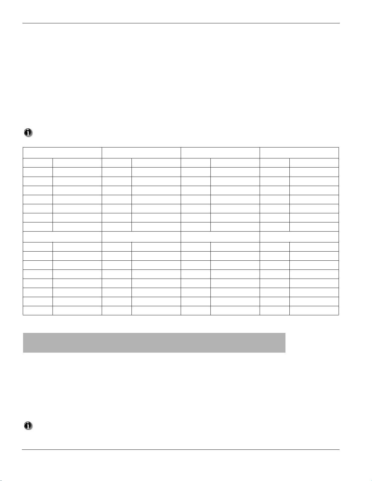
PowerSeries - PC1616/PC1832/PC1864
Partition Programming
[201] Partition Selection Mask
Opt Def ON OFF
1
2
3
4
5
6
7
8
Partition 1 is enabled
Partition 2 is enabled
Partition 3 is enabled
Partition 4 is enabled
Partition 5 is enabled
Partition 6 is enabled
Partition 7 is enabled
Partition 8 is enabled
For the PC1864 and PC1832, the default setting is partition 1, zones 1-16 ON. For the PC1616, the default setting is partition 1, zones 1-6 ON.
Partition 1 Zone Assignment Partition 2 Zone Assignment Partition 3 Zone Assignment Par tition 4 Zone Assignment
[202] 1-8 [210] 1-8 [218] 1-8 [226] 1-8
[203] 9-16 [211] 9-16 [219] 9-16 [227] 9-16
[204] 17-24 [212] 17-24 [220] 17-24 [228] 17-24
[205] 25-32 [213] 25-32 [221] 25-32 [229] 25-32
[206] 33-40 [214] 33-40 [222] 33-40 [230] 33-40
[207] 41-48 [215] 41-48 [223] 41-48 [231] 41-48
[208] 49-56 [216] 49-56 [224] 49-56 [232] 49-56
[209] 57-64 [217] 57-64 [225] 57-64 [233] 57-64
Partition 5 Zone Assignment Partition 6 Zone Assignment Partition 7 Zone Assignment Par tition 8 Zone Assignment
[234] 1-8 [242] 1-8 [250] 1-8 [258] 1-8
[235] 9-16 [243] 9-16 [251] 9-16 [259] 9-16
[236] 17-24 [244] 17-24 [252] 17-24 [260] 17-24
[237] 25-32 [245] 25-32 [253] 25-32 [261] 25-32
[238] 33-40 [246] 33-40 [254] 33-40 [262] 33-40
[239] 41-48 [247] 41-48 [255] 41-48 [263] 41-48
[240] 49-56 [248] 49-56 [256] 49-56 [264] 49-56
[241] 57-64 [249] 57-64 [257] 57-64 [265] 57-64
Cannot be disabled
Disabled
Disabled
Disabled
Disabled
Disabled
Disabled
Disabled
Communications
[301] First Telephone Number (32 Digits)
I__D__I_____I_____I_____I_____I_____I_____I_____I_____I_____I_____I_____I_____I_____I_____I_____I_____I_____I_____I_____I_____I_____I_____I_____I_____I_____I_____I_____I_____I_____I_____I_____I
[302] Second Telephone Number (32 Digits)
I__D___I_____I_____I_____I_____I_____I_____I_____I_____I_____I_____I_____I_____I_____I_____I_____I_____I_____I_____I_____I_____I_____I_____I_____I_____I_____I_____I_____I_____I_____I_____I_____I
[303] Third Telephone Number (32 Digits)
I__D__I_____I_____I_____I_____I_____I_____I_____I_____I_____I_____I_____I_____I_____I_____I_____I_____I_____I_____I_____I_____I_____I_____I_____I_____I_____I_____I_____I_____I_____I_____I_____|
[304] Call Waiting Cancel String (6 Digits) - This feature is activated in [382] Option 4
I_______I_______I_______I_______I_ ______I_______I Default = DB70EF Program unused digits with Hex F
All six digits must be entered for changes to be saved. Fill unused digit spaces with ‘F’.
40
Page 44
Chapter 5 Programming Worksheets
Account Codes
Enter a 6-digit account number for the system account code. SIA will use this account code for all eight partitions. Only SIA supports
6-digit account codes. If the last two digits of the account code are FF, the panel will only use the first four digits.
Section [310] System Account Code [FFFFFF]
I_______I_______I_______I_______I_______I_______I
Enter a four-digit account number for each active partition.
[311] Partition 1 Account Number
[312] Partition 2 Account Number
[313] Partition 3 Account Number
[314] Partition 4 Account Number
[315] Partition 5 Account Number
[316] Partition 6 Account Number
[317] Partition 7 Account Number
[318] Partition 8 Account Number
|_______I_______I_______I_______I
|_______I_______I_______I_______I
|_______I_______I_______I_______I
|_______I_______I_______I_______I
|_______I_______I_______I_______I
|_______I_______I_______I_______I
|_______I_______I_______I_______I
|_______I_______I_______I_______I
All Account Number codes are defaulted to FFFF.
Reporting Codes
[320]-[323] Alarm Reporting Codes, Zones 01-64
All Reporting Codes defaulted to FF unless otherwise indicated.
Section
[320]
[321] Zone 17 Zone 18 Zone 19 Zone 20 Zone 21 Zone 22 Zone 23 Zone 24
[322] Zone 33 Zone 34 Zone 35 Zone 36 Zone 37 Zone 38 Zone 39 Zone 40
[323] Zone 49 Zone 50 Zone 51 Zone 52 Zone 53 Zone 54 Zone 55 Zone 56
[324]-[327] Alarm Restoral Reporting Codes, Zones 01-64
Section
[324]
[325] Zone 17 Zone 18 Zone 19 Zone 20 Zone 21 Zone 22 Zone 23 Zone 24
[326] Zone 33 Zone 34 Zone 35 Zone 36 Zone 37 Zone 38 Zone 39 Zone 40
[327] Zone 49 Zone 50 Zone 51 Zone 52 Zone 53 Zone 54 Zone 55 Zone 56
Zone 01 Zone 02 Zone 03 Zone 04 Zone 05 Zone 06 Zone 07 Zone 08
I_______I_______I I_______I_______I I_______I_______I I_______I_______I I_______I_______I I_______I_______I I_______I_______I I_______I_______I
Zone 09 Zone 10 Zone 11 Zone 12 Zone 13 Zone 14 Zone 15 Zone 16
I_______I_______I I_______I_______I I_______I_______I I_______I_______I I_______I_______I I_______I_______I I_______I_______I I_______I_______I
I_______I_______I I_______I_______I I_______I_______I I_______I_______I I_______I_______I I_______I_______I I_______I_______I I_______I_______I
Zone 25 Zone 26 Zone 27 Zone 28 Zone 29 Zone 30 Zone 31 Zone 32
I_______I_______I I_______I_______I I_______I_______I I_______I_______I I_______I_______I I_______I_______I I_______I_______I I_______I_______I
I_______I_______I I_______I_______I I_______I_______I I_______I_______I I_______I_______I I_______I_______I I_______I_______I I_______I_______I
Zone 41 Zone 42 Zone 43 Zone 44 Zone 45 Zone 46 Zone 47 Zone 48
I_______I_______I I_______I_______I I_______I_______I I_______I_______I I_______I_______I I_______I_______I I_______I_______I I_______I_______I
I_______I_______I I_______I_______I I_______I_______I I_______I_______I I_______I_______I I_______I_______I I_______I_______I I_______I_______I
Zone 57 Zone 58 Zone 59 Zone 60 Zone 61 Zone 62 Zone 63 Zone 64
I_______I_______I I_______I_______I I_______I_______I I_______I_______I I_______I_______I I_______I_______I I_______I_______I I_______I_______I
Zone 01 Zone 02 Zone 03 Zone 04 Zone 05 Zone 06 Zone 07 Zone 08
I_______I_______I I_______I_______I I_______I_______I I_______I_______I I_______I_______I I_______I_______I I_______I_______I I_______I_______I
Zone 09 Zone 10 Zone 11 Zone 12 Zone 13 Zone 14 Zone 15 Zone 16
I_______I_______I I_______I_______I I_______I_______I I_______I_______I I_______I_______I I_______I_______I I_______I_______I I_______I_______I
I_______I_______I I_______I_______I I_______I_______I I_______I_______I I_______I_______I I_______I_______I I_______I_______I I_______I_______I
Zone 25 Zone 26 Zone 27 Zone 28 Zone 29 Zone 30 Zone 31 Zone 32
I_______I_______I I_______I_______I I_______I_______I I_______I_______I I_______I_______I I_______I_______I I_______I_______I I_______I_______I
I_______I_______I I_______I_______I I_______I_______I I_______I_______I I_______I_______I I_______I_______I I_______I_______I I_______I_______I
Zone 41 Zone 42 Zone 43 Zone 44 Zone 45 Zone 46 Zone 47 Zone 48
I_______I_______I I_______I_______I I_______I_______I I_______I_______I I_______I_______I I_______I_______I I_______I_______I I_______I_______I
I_______I_______I I_______I_______I I_______I_______I I_______I_______I I_______I_______I I_______I_______I I_______I_______I I_______I_______I
Zone 57 Zone 58 Zone 59 Zone 60 Zone 61 Zone 62 Zone 63 Zone 64
I_______I_______I I_______I_______I I_______I_______I I_______I_______I I_______I_______I I_______I_______I I_______I_______I I_______I_______I
41
Page 45

PowerSeries - PC1616/PC1832/PC1864
[328] Miscellaneous Alarm Reporting Codes
I_______I_______I Duress Alarm
I_______I_______I Opening After Alarm
I_______I_______I Recent Closing
I_______I_______I Zone Expander Supervisory Alarm
I_______I_______I Zone Expander Supervisory Restore
I_______I_______I Cross Zone Police Code Alarm
I_______I_______I Burglary Not Verified
I_______I_______I Alarm Cancelled
[329] Priority Alarm and Restoral
I_______I_______I Keypad Fire Alarm
I_______I_______I Keypad Auxiliary Alarm
I_______I_______I Keypad Panic Alarm
I_______I_______I Auxiliary Input Alarm
I_______I_______I Keypad Fire Restoral
I_______I_______I Keypad Auxiliary Restoral
I_______I_______I Keypad Panic Restoral
I_______I_______I Auxiliary Input Restore
[330]-[333] Tamper Reporting Codes, Zones 01-64
Section
[330]
Zone 01 Zone 02 Zone 03 Zone 04 Zone 05 Zone 06 Zone 07 Zone 08
I_______I_______I I_______I_______I I_______I_______I I_______I_______I I_______I_______I I_______I_______I I_______I_______I I_______I_______I
Zone 09 Zone 10 Zone 11 Zone 12 Zone 13 Zone 14 Zone 15 Zone 16
I_______I_______I I_______I_______I I_______I_______I I_______I_______I I_______I_______I I_______I_______I I_______I_______I I_______I_______I
[331] Zone 17 Zone 18 Zone 19 Zone 20 Zone 21 Zone 22 Zone 23 Zone 24
I_______I_______I I_______I_______I I_______I_______I I_______I_______I I_______I_______I I_______I_______I I_______I_______I I_______I_______I
Zone 25 Zone 26 Zone 27 Zone 28 Zone 29 Zone 30 Zone 31 Zone 32
I_______I_______I I_______I_______I I_______I_______I I_______I_______I I_______I_______I I_______I_______I I_______I_______I I_______I_______I
[332] Zone 33 Zone 34 Zone 35 Zone 36 Zone 37 Zone 38 Zone 39 Zone 40
I_______I_______I I_______I_______I I_______I_______I I_______I_______I I_______I_______I I_______I_______I I_______I_______I I_______I_______I
Zone 41 Zone 42 Zone 43 Zone 44 Zone 45 Zone 46 Zone 47 Zone 48
I_______I_______I I_______I_______I I_______I_______I I_______I_______I I_______I_______I I_______I_______I I_______I_______I I_______I_______I
[333] Zone 49 Zone 50 Zone 51 Zone 52 Zone 53 Zone 54 Zone 55 Zone 56
I_______I_______I I_______I_______I I_______I_______I I_______I_______I I_______I_______I I_______I_______I I_______I_______I I_______I_______I
Zone 57 Zone 58 Zone 59 Zone 60 Zone 61 Zone 62 Zone 63 Zone 64
I_______I_______I I_______I_______I I_______I_______I I_______I_______I I_______I_______I I_______I_______I I_______I_______I I_______I_______I
[334]-[337] Tamper Restoral Reporting Codes, Zones 01-64
Section
[334]
[335] Zone 17 Zone 18 Zone 19 Zone 20 Zone 21 Zone 22 Zone 23 Zone 24
[336] Zone 33 Zone 34 Zone 35 Zone 36 Zone 37 Zone 38 Zone 39 Zone 40
[337] Zone 49 Zone 50 Zone 51 Zone 52 Zone 53 Zone 54 Zone 55 Zone 56
Zone 01 Zone 02 Zone 03 Zone 04 Zone 05 Zone 06 Zone 07 Zone 08
I_______I_______I I_______I_______I I_______I_______I I_______I_______I I_______I_______I I_______I_______I I_______I_______I I_______I_______I
Zone 09 Zone 10 Zone 11 Zone 12 Zone 13 Zone 14 Zone 15 Zone 16
I_______I_______I I_______I_______I I_______I_______I I_______I_______I I_______I_______I I_______I_______I I_______I_______I I_______I_______I
I_______I_______I I_______I_______I I_______I_______I I_______I_______I I_______I_______I I_______I_______I I_______I_______I I_______I_______I
Zone 25 Zone 26 Zone 27 Zone 28 Zone 29 Zone 30 Zone 31 Zone 32
I_______I_______I I_______I_______I I_______I_______I I_______I_______I I_______I_______I I_______I_______I I_______I_______I I_______I_______I
I_______I_______I I_______I_______I I_______I_______I I_______I_______I I_______I_______I I_______I_______I I_______I_______I I_______I_______I
Zone 41 Zone 42 Zone 43 Zone 44 Zone 45 Zone 46 Zone 47 Zone 48
I_______I_______I I_______I_______I I_______I_______I I_______I_______I I_______I_______I I_______I_______I I_______I_______I I_______I_______I
I_______I_______I I_______I_______I I_______I_______I I_______I_______I I_______I_______I I_______I_______I I_______I_______I I_______I_______I
Zone 57 Zone 58 Zone 59 Zone 60 Zone 61 Zone 62 Zone 63 Zone 64
I_______I_______I I_______I_______I I_______I_______I I_______I_______I I_______I_______I I_______I_______I I_______I_______I I_______I_______I
42
Page 46

Chapter 5 Programming Worksheets
[338] Miscellaneous Tamper Reporting Codes
I_______I_______I General System Tamper
I_______I_______I General System Tamper Rest.
I_______I_______I Keypad Lockout
[339]-[340] Closing (Arming) Reporting Codes, Access Codes 1-32
Section
[339]
Code 1 Code 2 Code 3 Code 4 Code 5 Code 6 Code 7 Code 8
I_______I_______I I_______I_______I I_______I_______I I_______I_______I I_______I_______I I_______I_______I I_______I_______I I_______I_______I
Code 9 Code 10 Code 11 Code 12 Code 13 Code 14 Code 15 Code 16
I_______I_______I I_______I_______I I_______I_______I I_______I_______I I_______I_______I I_______I_______I I_______I_______I I_______I_______I
[340] Code 17 Code 18 Code 19 Code 20 Code 21 Code 22 Code 23 Code 24
I_______I_______I I_______I_______I I_______I_______I I_______I_______I I_______I_______I I_______I_______I I_______I_______I I_______I_______I
Code 25 Code 26 Code 27 Code 28 Code 29 Code 30 Code 31 Code 32
I_______I_______I I_______I_______I I_______I_______I I_______I_______I I_______I_______I I_______I_______I I_______I_______I I_______I_______I
[341] Miscellaneous Closing (Arming) Reporting Codes
I_______I_______I For Future Use
I_______I_______I For Future Use
I_______I_______I For Future Use
I_______I_______I For Future Use
I__ 0__I__ 0__I Automatic Zone Bypass
I_______I_______I Partial Closing
I_______I_______I Special Closing
I_______I_______I Late to Close
I_______I_______I Exit Fault
[342]-[343] Opening (Disarming) Reporting Codes, Access Codes 1-32
Section
[342]
Code 1 Code 2 Code 3 Code 4 Code 5 Code 6 Code 7 Code 8
I_______I_______I I_______I_______I I_______I_______I I_______I_______I I_______I_______I I_______I_______I I_______I_______I I_______I_______I
Code 9 Code 10 Code 11 Code 12 Code 13 Code 14 Code 15 Code 16
I_______I_______I I_______I_______I I_______I_______I I_______I_______I I_______I_______I I_______I_______I I_______I_______I I_______I_______I
[343] Code 17 Code 18 Code 19 Code 20 Code 21 Code 22 Code 23 Code 24
I_______I_______I I_______I_______I I_______I_______I I_______I_______I I_______I_______I I_______I_______I I_______I_______I I_______I_______I
Code 25 Code 26 Code 27 Code 28 Code 29 Code 30 Code 31 Code 32
I_______I_______I I_______I_______I I_______I_______I I_______I_______I I_______I_______I I_______I_______I I_______I_______I I_______I_______I
[344] Miscellaneous Opening (Disarming) Reporting Codes
I_______I_______I
I_______I_______I
I_______I_______I
I_______I_______I
I_______I_______I
I_______I_______I
I_______I_______I
For Future Use
For Future Use
For Future Use
For Future Use
For Future Use
Auto Arm Cancellation/Postpone
Special Opening
[345] Maintenance Alarm Reporting Codes [346] Maintenance Restoral Reporting Codes
I_______I_______I
I_______I_______I
I_______I_______I
I_______I_______I
I_______I_______I
I_______I_______I
I_______I_______I
I_______I_______I
I_______I_______I
Battery Trouble Alarm
AC Failure Trouble Alarm
Bell Circuit Trouble Alarm
Fire Trouble Alarm
Auxiliary Power Supply Trouble Alarm
TLM Trouble Code
General System Trouble
General System Supervisory
For Future Use
I_______I_______I
I_______I_______I
I_______I_______I
I_______I_______I
I_______I_______I
I_______I_______I
I_______I_______I
I_______I_______I
I_______I_______I
43
Battery Trouble Restoral
AC Failure Trouble Restoral
Bell Circuit Trouble Restoral
Fire Trouble Restoral
Auxiliary Power Supply Trouble Restoral
TLM Restoral
General System Trouble Restoral
General System Supervisory Restoral
Cold Start
Page 47

PowerSeries - PC1616/PC1832/PC1864
[347] Miscellaneous Maintenance Reporting Codes [348] Test Transmission Reporting Codes
I_______I_______I
I_______I_______I
I_______I_______I
I___0___I___0__I
I___0___I___0__I
I_______I_______I
I_______I_______I
I_______I_______I
I_______I_______I
I_______I_______I
I___0___I___0__I
I___0___I___0__I
Telephone Number 1 FTC Restore
Telephone Number 2 FTC Restore
Event Buffer 75% Full Since Last Upload
DLS Lead IN
DLS Lead OUT
Zone Fault Alarm
Zone Fault Restore
Delinquency Code
General Zone Low Battery Alarm
General Zone Low Battery Restoral
Installer Lead Out
Installer Lead In
I_______I_______I
I_______I_______I
I_______I_______I
I_______I_______I
I_______I_______I
I_______I_______I
Walk Test End
Walk Begin
Periodic Test Transmission with Trouble
Periodic Test Transmission
System Test
For Future Use
[349] PC5700 Maintenance Reporting Codes (only available in Canada)
I_______I_______I
I_______I_______I
I_______I_______I
I_______I_______I
I_______I_______I
I_______I_______I
PC5700 Ground Fault Trouble
PC5700 Ground Fault Restore
PC5700 TLM Line 1 Trouble
PC5700 TLM Line 1 Restore
PC5700 TLM Line 2 Trouble
PC5700 TLM Line 2 Restore
[350] Communicator Format Options
Default
04 I_______I_______I 1st Telephone Number
04
I_______I_______I 2nd Telephone Number
01 20 BPS, 1400 HZ handshake 05 Pager 08 10 BPS, 2300Hz handshake
02 20 BPS, 2300 HZ handshake 06 Residential Dial** 09-13 For Future Use
03 DTMF CONTACT ID 07 10 BPS, 1400Hz handshake
04 SIA FSK
**Failure to communicate using Residential Dial will not generate a Failed To Communicate Trouble.
Call Direction Options
[351]-[358] Alarm/Restore Communicator Call Directions
Section Par tition
[351] 1
[352] 2
[353] 3
[354] 4
[355] 5
[356] 6
[357] 7
[358] 8
Option 1
1st Telephone
Number (Def ON)
I________I I________I I________I I________I I________I I________I
I________I I________I I________I I________I I________I I________I
I________I I________I I________I I________I I________I I________I
I________I I________I I________I I________I I________I I________I
I________I I________I I________I I________I I________I I________I
I________I I________I I________I I________I I________I I________I
I________I I________I I________I I________I I________I I________I
I________I I________I I________I I________I I________I I________I
Option 2
2nd Telephone
Number (Def OFF)
Option 3
Not Used
(Def OFF)
Option 4
Not Used
(Def OFF)
[359]-[366] Tamper/Restore Communicator Call Directions
Section Partition
[359] 1
[360] 2
[361] 3
[362] 4
[363] 5
[364] 6
[365] 7
[366] 8
Option 1
1st Telephone
Number (Def ON)
I________I I________I I________I I________I I________I I________I
I________I I________I I________I I________I I________I I________I
I________I I________I I________I I________I I________I I________I
I________I I________I I________I I________I I________I I________I
I________I I________I I________I I________I I________I I________I
I________I I________I I________I I________I I________I I________I
I________I I________I I________I I________I I________I I________I
I________I I________I I________I I________I I________I I________I
Option 2
2nd Telephone
Number (Def OFF)
Option 3
Not Used
(Def OFF)
Option 4
Not Used
(Def OFF)
Option 5
Alt Comm
(Def ON)
Option 5
Alt Comm
(Def ON)
Options 6,7,8
Future Use
Options 6,7,8
Future Use
44
Page 48

[367]-[374] Opening/Closing Communicator Call Directions
Section Partition
[367]
[368]
[369]
[370]
[371]
[372]
[373]
[374]
1
2
3
4
5
6
7
8
Option 1
1st Telephone
Number (Def OFF)
I________I I________I I________I I________I I________I I________I
I________I I________I I________I I________I I________I I________I
I________I I________I I________I I________I I________I I________I
I________I I________I I________I I________I I________I I________I
I________I I________I I________I I________I I________I I________I
I________I I________I I________I I________I I________I I________I
I________I I________I I________I I________I I________I I________I
I________I I________I I________I I________I I________I I________I
Option 2
2nd Telephone
Number (Def OFF)
Option 3
Not Used
(Def OFF)
[375] System Maintenance Communicator Call Directions
Section Partition
[375]
Option 1
1st Telephone
Number (Def ON)
I________I I________I I________I I________I I________I I________I
Option 2
2nd Telephone
Number (Def OFF)
Option 3
Not Used
(Def OFF)
[376] System Test Transmissions Communicator Call Directions
Section Partition
[376]
Option 1
1st Telephone
Number (Def ON)
I________I I________I I________I I________I I________I I________I
Option 2
2nd Telephone
Number (Def OFF)
Option 3
Not Used
(Def OFF)
Option 4
Not Used
(Def OFF)
Option 4
Not Used
(Def OFF)
Option 4
Not Used
(Def OFF)
Chapter 5 Programming Worksheets
Option 5
Alt Comm
(Def OFF)
Option 5
Alt Comm
(Def ON)
Option 5
Alt Comm
(Def ON)
Options 6,7,8
Future Use
Options 6,7,8
Future Use
Options 6,7,8
Future Use
[377] Communication Variables
The values in gray are required for CP-01 compliant systems.
Default
003 I___0__I__0__I___1__I Swinger Shutdown (Alarms and Rest) 001-014 Transmissions; 000=disabled
003
I___0__I__0__I___3__I Swinger Shutdown (Tampers and Rest) 001-014 Transmissions; 000=disabled
003 I___0__I__0__I___3__I Swinger Shutdown (Maintenance and Rest) 001-014 Transmissions; 000=disabled
000 I___0__I__3__I___0__I Communication Delay* 000-255 seconds
030
I___0__I__3__I___0__I AC Failure Communication Delay 001-255 hours/minutes**; 000=disabled
010 I___0__I__1__I___0__I TLM Trouble Delay No. of checks required - valid entries 003 - 255
030 I___0__I__3__I___0__I Test Transmission Cycle (land line) 001-255 days/minutes***
030
007
030
000
I___0__I__3__I___0__I For Future Use
I___0__I__0__I___7__I Zone Low Battery Transmission Delay 000-255 days
I___0__I__3__I___0__I Delinquency Transmission Cycle 000-255 days/hours****
I___0__I__0__I___5__I Communications Cancelled Window 000-255 minutes
* For UL installations, the Entry Delay plus Communication Delay time must not exceed 60 seconds.
**Dependent on programming in [382], Option [6].
***Dependent on programming in [702], Option [3].
****Dependent on programming in [380], Option [8].
[378] Test Transmission Time of Day
Default
9999 I_______I_______I_______I_______I Valid entries are 0000-2359 (9999 to disable)
[379] Periodic DLS Time of Day
Default
FFFF I_______I_______I_______I_______I Valid entries are 0000-2359 (9999 for Random; FFFF to disable)
45
Page 49

PowerSeries - PC1616/PC1832/PC1864
[380] First Communicator Options
Opt Def ON OFF
1
2
3
4
5
6
7
8
J
Communications Enabled
Restorals on Bell Time-out
J
Pulse Dialing
J
Switch to Pulse Dialing on 5th Attempt
J
3rd Telephone Number Enabled
J
Alternate Dial (1st & 3rd)
J
For Future Use
J
Delinquency Follows Zone Activity (Hours)
J
J
J
J
J
J
J
J
J
Communications Disabled
Restorals Follow Zones
DTMF Dialing
DTMF Dial For All Attempts
3rd Telephone Number Disabled
Call 1st Number, Back up to 3rd
Delinquency Follows Arming (Days)
[381] Second Communicator Options
Opt Def ON OFF
1
2
3
4
5
6
7
8
J
J
Open After Alarm Keypad Ringback Enabled
J
Open After Alarm Bell Ringback Enabled
J
SIA Sends Programmed Reporting Codes
J
Closing Confirmation Enabled
J
Talk/Listen on Phone Lines 1/3
Talk/Listen on Phone Line 2
Contact ID Uses Programmed Reporting Codes
J
ULC Communications Priority Enabled
J
J
J
J
J
J
J
J
J
Open After Alarm Keypad Ringback Disabled
Open After Alarm Bell Ringback Disabled
SIA Sends Automatic Reporting Codes
Closing Confirmation Disabled
No Talk/Listen on Phone Lines 1/3
No Talk/Listen on Phone Line 2
Contact ID Uses Automatic Reporting Codes
ULC Communications Priority Disabled/Standard Priority
Followed
[382] Third Communicator Options
Opt Def ON OFF
1
2
3
4
5
6
7
8
*This option must remain OFF for SIA CP-01 installations.
** A Call Waiting Cancel on a non-Call Waiting line will prevent successful connection to the central station.
For Future Use
J
Alarm Communications Enabled During Walk Test*
J
Communication Cancelled Message Enabled (ON for SIA CP-01)
J
Call Waiting Cancel Enabled**
J
T-Link Interface Enabled
J
AC Failure Transmission Delay is in Hours
J
Number of Dialing Attempt for Residential Dial is 1
J
For Future Use
J
J
Alarm Communications Disabled During Walk Test
J
Communication Cancelled Message Disabled
J
Call Waiting Cancel Disabled
J
T-Link Interface Disabled
J
AC Failure Transmission Delay is in Minutes
J
Residential Dial Follows Dialing Attempts Counter
J
J
[383] Fourth Communicator Options
Opt Def ON OFF
1
2-8
Account Code Follows Phone Number
J
For Future Use
J
Account Code Follows Partition
J
J
[389] TL/GS Module Fault Check Timer
Default: 003 I_______I__ _____I_______I Enter no. of checks X 3 seconds - valid entries 002 to 255
46
Page 50
Chapter 5 Programming Worksheets
DLS Downloading
[401] Downloading Option Codes
Opt Def ON OFF
1
2
3
4
5
6
7-8
[402] DLS Downloading Telephone Number (32 Digits)
|____D___|_______|_______|_______|_______|_______|_______|_____ __|_______|_______|_______|_______|_______|_______|______ _|_______|_______|_______|_______|_______|_______|_______ |_______|_______|_______|_______|_______|_______|_______|_____ __|_______|_______|
[403]-[404] DLS Downloading Access Code / Panel ID Code (Enter 6 Hexadecimal Digits)
Panel Default [403] Downloading Access Code [404] Panel ID Code
PC1616 161600
PC1832 183200
PC1864 186400
Answering Machine/Double Call enabled
User Can Enable DLS Window
Call Back enabled
User Initiated Call Up enabled
Auto Event Buffer Upload enabled
300 Baud Call Up
For Future Use
|_______|_______|_______|_______|_______|_______| |_______|_______|_______|_______|_______|_______|
|_______|_______|_______|_______|_______|_______| |_______|_______|_______|_______|_______|_______|
|_______|_______|_______|_______|_______|_______| |_______|_______|_______|_______|_______|_______|
Answering Machine/Double Call disabled
User Cannot Enable DLS Window
Call Back disabled
User Initiated Call Up disabled
Auto Event Buffer Upload disabled
110 Baud Call Up
[405] Answering Machine Double Call Timer [406] Number of Rings to Answer On
Default 060 I_______I_______I_______I (001-255 seconds) Default 000 I_______I_______I_______I (000-255 rings)
[499] Initiate PC-Link Downloading
Enter [499][Installer Code][499]
[501]- [554] Programmable Output Attributes
Program only the following attributes for the PGM options listed. All others will be ignored. PGM options are programmed in [009], [010] & [011].
PGM Attribute Defaults (Y = Attribute ON; N = Attribute OFF; Blank = Attribute not available):
Attribute: 12 3 4 5 678
ON Not
used
OFF — — Inverted On / Off No Code
PGM Option
[01] Residential Burglary / Fire Bell Output Y
[02] For Future Use
[03] Sensor Reset [
[04] 2-Wire Smoke Support (PGM2 only) Y
[05] System Armed Status Y
[06] Ready To Arm Y
[07] Keypad Buzzer Follower Mode Y
[08] Courtesy Pulse Y
[11] System Tamper (all sources) Y
[12] TLM and Alarm Y
[13] Kiss-off Output YY
[14] Ground Start Pulse YY
[15] Remote Operation (DLS Support) YY
[16] For Future Use Y
[17] Away Armed Status Y
[18] Stay Armed Status Y
[19] Command Output #1, [
[20] Command Output #2, [
[21] Command Output #3, [
[22] Command Output #4, [
][7][2] Y
][7][1] Y Y Y
][7][2] Y Y N
][7][3] Y Y N
][7][4] Y Y N
Not
used
True
Output
Follows
Timer
Code Req. Not
Req.
used
———
Not
used
Not
used
47
Page 51
PowerSeries - PC1616/PC1832/PC1864
[23] 24-hr Silent Input (PGM2 only) Y
[24] 24-hr Audible Input (PGM2 only) Y
[25] Delayed Burglary & Fire Output Y
[26] Battery Test Output Y
[28] Holdup Output Y
[30] Partition Status Alarm Memory Output Y
[33] For Future Use
[34] Away Armed with no Zone Bypassed Status Y
Attribute:
PGM Option
ON
OFF
[09] System Trouble Y Y YYYY Y Y
ON
OFF
[10] System Event Y Y YYYYY N
ON
OFF
[31] Alternate
Communicator
ON
OFF
[29], [35]-[41] Zone Follower N N Y NNNN N
1 2 3456 7 8
Serv. req. AC Fail TLM Fault FTC Zone Fault Zone Tmp. Zn. Low
Disabled Disabled Disabled Disabled Disabled Disabled Disabled Disabled
Burg. Evnt. Fire Evnt. Panic Evnt. Med. Evnt. Supv. Evnt. Priority
Disabled Disabled Disabled Disabled Disabled Disabled Disabled Latched
Fire Alarm Panic Alarm Burglary
Alarm
Disabled Disabled Disabled Disabled Disabled Disabled Disabled Latched
N N NNNNN N
Future Use Future Use True Output Future Use Future Use Future Use Future Use AND Logic
Inverted OR Logic
Open/
Close
Zone Auto
Bypass
Evnt.
Medical
Alarm
Bat.
Holdup
Evnt.
Police
Code
Loss of
Clock
Follows
Timer*
Active When
true
Section PGM Output 1 2 3 4 5 6 7 8
# Type*
Main Board
[501] 1 ( ) I________I I________| I________| I________| I________| I________| I________| I________I
[502] 2 ( ) I________I I________| I________| I________| I________| I________| I________| I________I
Main Board / PC5208
[503] ** 3 ( ) I_____ ___I I________| I________| I________| I________| I________| I________| I________I
[504] ** 4 ( ) I________I I________| I________| I________| I________ | I________| I________| I________I
*Record here based on programming in [009], [010] and [011].
** These sections allow you to program both PGM3 and PGM4 on the main panel, and the first two PGM outputs on the PC5208. If you use both the main
panel and the PC5208 outputs, PGM3 will work identically to the first PC5208 output, and PGM4 will work identically to the second PC5208 output.
Section PGM Output 1 2 3 4 5 6 7 8
#Type*
PC5208
[505] 5 ( ) I________I I________| I________| I________| I________| I________| I________| I________I
[506] 6 ( ) I________I I________| I________| I________| I________| I________| I________| I________I
[507] 7 ( ) I________I I________| I________| I________| I________| I________| I________| I________I
[508] 8 ( ) I________I I________| I________| I________| I________| I________| I________| I________I
[509] 9 ( ) I________I I________| I________| I________| I________| I________| I________| I________I
[510] 10 ( ) I________I I________| I________| I________| I________| I________| I________| I________I
PC5204
[511] 11 ( ) I________I I________| I________| I________| I________| I________| I________| I________I
[512] 12 ( ) I________I I________| I________| I________| I________| I________| I________| I________I
[513] 13 ( ) I________I I________| I________| I________| I________| I________| I________| I________I
[514] 14 ( ) I________I I________| I________| I________| I________| I________| I________| I________I
*Record here based on programming in [009], [010] and [011].
48
Page 52
Chapter 5 Programming Worksheets
PGM Output Partition Assignment
Section PGM Partition: 1 2 3 4 5 6 7 8
#
Main Board
[551] 1 I________I I___ _____| I________| I________| I________| I________| I________| I________I
[552] 2 I________I I___ _____| I________| I________| I________| I________| I________| I________I
Main Board / PC5208
[553] 3 I________I I___ _____| I________| I________| I________| I________| I________| I________I
[554] 4 I________I I___ _____| I________| I________| I________| I________| I________| I________I
PC5208
[555] 5 I__ ______I I________| I________| I________| I_ _______| I________| I________| I________I
[556] 6 I________I I___ _____| I________| I________| I________| I________| I________| I________I
[557] 7 I________I I___ _____| I________| I________| I________| I________| I________| I________I
[558] 8 I________I I___ _____| I________| I________| I________| I________| I________| I________I
[559] 9 I________I I___ _____| I________| I________| I________| I________| I________| I________I
[560] 10 I________I I________| I________| I________| I________ | I________| I________| I________I
PC5204
[561] 11 I________I I________| I________| I________| I________ | I________| I________| I________I
[562] 12 I________I I________| I________| I________| I________ | I________| I________| I________I
[563] 13 I________I I________| I________| I________| I________ | I________| I________| I________I
[564] 14 I________I I________| I________| I________| I________ | I________| I________| I________I
Zone Follower PGM Zone Assignment
If a Zone Follower PGM type 29, 35-41 is used, the PGM Output Partition Assignment will be treated as a PGM Output Zone Assignment. Each Zone Follower PGM applies to a different bank of zones, as in the following table. Record the assignments above.
Option:12345678
[29] Zone Follower (1-8)
[35] Zone Follower (9-16)
[36] Zone Follower (17-24)
[37] Zone Follower (25-32)
[38] Zone Follower (33-40)
[39] Zone Follower (41-48)
[40] Zone Follower (49-56)
[41] Zone Follower (57-64)
Zone 1 Zone 2 Zone 3 Zone 4 Zone 5 Zone 6 Zone 7 Zone 8
Zone 9 Zone 10 Zone 11 Zone 12 Zone 13 Zone 14 Zone 15 Zone 16
Zone 17 Zone 18 Zone 19 Zone 20 Zone 21 Zone 22 Zone 23 Zone 24
Zone 25 Zone 26 Zone 27 Zone 28 Zone 29 Zone 30 Zone 31 Zone 32
Zone 33 Zone 34 Zone 35 Zone 36 Zone 37 Zone 38 Zone 39 Zone 40
Zone 41 Zone 42 Zone 43 Zone 44 Zone 45 Zone 46 Zone 47 Zone 48
Zone 49 Zone 50 Zone 51 Zone 52 Zone 53 Zone 54 Zone 55 Zone 56
Zone 57 Zone 58 Zone 59 Zone 60 Zone 61 Zone 62 Zone 63 Zone 64
Extended Reporting Codes
[601]-[604] Closing (Arming) Reporting Codes, Access Codes 33-95
Section
[601]
[602] Code 49 Code 50 Code 51 Code 52 Code 53 Code 54 Code 55 Code 56
[603] Code 65 Code 66 Code 67 Code 68 Code 69 Code 70 Code 71 Code 72
[604] Code 81 Code 82 Code 83 Code 84 Code 85 Code 86 Code 87 Code 88
Code 33 Code 34 Code 35 Code 36 Code 37 Code 38 Code 39 Code 40
I_______I_______I I_______I_______I I_______I_______I I_______I_______I I_______I_______I I_______I_______I I_______I_______I I_______I_______I
Code 41 Code 42 Code 43 Code 44 Code 45 Code 46 Code 47 Code 48
I_______I_______I I_______I_______I I_______I_______I I_______I_______I I_______I_______I I_______I_______I I_______I_______I I_______I_______I
I_______I_______I I_______I_______I I_______I_______I I_______I_______I I_______I_______I I_______I_______I I_______I_______I I_______I_______I
Code 57 Code 58 Code 59 Code 60 Code 61 Code 62 Code 63 Code 64
I_______I_______I I_______I_______I I_______I_______I I_______I_______I I_______I_______I I_______I_______I I_______I_______I I_______I_______I
I_______I_______I I_______I_______I I_______I_______I I_______I_______I I_______I_______I I_______I_______I I_______I_______I I_______I_______I
Code 73 Code 74 Code 75 Code 76 Code 77 Code 78 Code 79 Code 80
I_______I_______I I_______I_______I I_______I_______I I_______I_______I I_______I_______I I_______I_______I I_______I_______I I_______I_______I
I_______I_______I I_______I_______I I_______I_______I I_______I_______I I_______I_______I I_______I_______I I_______I_______I I_______I_______I
Code 89 Code 90 Code 91 Code 92 Code 93 Code 94 Code 95
I_______I_______I I_______I_______I I_______I_______I I_______I_______I I_______I_______I I_______I_______I I_______I_______I
49
Page 53

PowerSeries - PC1616/PC1832/PC1864
[605]-[608] Opening (Disarming) Reporting Codes, Access Codes 33-95
Section
[605] Code 33 Code 34 Code 35 Code 36 Code 37 Code 38 Code 39 Code 40
I_______I_______I I_______I_______I I_______I_______I I_______I_______I I_______I_______I I_______I_______I I_______I_______I I_______I_______I
Code 41 Code 42 Code 43 Code 44 Code 45 Code 46 Code 47 Code 48
I_______I_______I I_______I_______I I_______I_______I I_______I_______I I_______I_______I I_______I_______I I_______I_______I I_______I_______I
[606] Code 49 Code 50 Code 51 Code 52 Code 53 Code 54 Code 55 Code 56
I_______I_______I I_______I_______I I_______I_______I I_______I_______I I_______I_______I I_______I_______I I_______I_______I I_______I_______I
Code 57 Code 58 Code 59 Code 60 Code 61 Code 62 Code 63 Code 64
I_______I_______I I_______I_______I I_______I_______I I_______I_______I I_______I_______I I_______I_______I I_______I_______I I_______I_______I
[607] Code 65 Code 66 Code 67 Code 68 Code 69 Code 70 Code 71 Code 72
I_______I_______I I_______I_______I I_______I_______I I_______I_______I I_______I_______I I_______I_______I I_______I_______I I_______I_______I
Code 73 Code 74 Code 75 Code 76 Code 77 Code 78 Code 79 Code 80
I_______I_______I I_______I_______I I_______I_______I I_______I_______I I_______I_______I I_______I_______I I_______I_______I I_______I_______I
[608] Code 81 Code 82 Code 83 Code 84 Code 85 Code 86 Code 87 Code 88
I_______I_______I I_______I_______I I_______I_______I I_______I_______I I_______I_______I I_______I_______I I_______I_______I I_______I_______I
Code 89 Code 90 Code 91 Code 92 Code 93 Code 94 Code 95
I_______I_______I I_______I_______I I_______I_______I I_______I_______I I_______I_______I I_______I_______I I_______I_______I
Automatic Disarming Schedule
Enter a four-digit number (HH:MM) for each day that the system will auto-disarm for each partition ([681] for Partition 1 through [688] for Partition
8). Valid entries are 0000-2359. All entries are disabled (9999) by default.
Sunday Monday Tuesday Wednesday Thursday Friday Saturday
I_______I_______I : I_______I_______I I_______I_______I : I_______I_______I I_______I_______I : I_______I_______I I____ ___I_______I : I_______I_______I I_______I_______I : I_______I_______I I_______I_______I : I_______I_______I I_______I_______I : I______ _I_______I
[681]
I_______I_______I : I_______I_______I I_______I_______I : I_______I_______I I_______I_______I : I_______I_______I I____ ___I_______I : I_______I_______I I_______I_______I : I_______I_______I I_______I_______I : I_______I_______I I_______I_______I : I______ _I_______I
[682]
I_______I_______I : I_______I_______I I_______I_______I : I_______I_______I I_______I_______I : I_______I_______I I____ ___I_______I : I_______I_______I I_______I_______I : I_______I_______I I_______I_______I : I_______I_______I I_______I_______I : I______ _I_______I
[683]
I_______I_______I : I_______I_______I I_______I_______I : I_______I_______I I_______I_______I : I_______I_______I I____ ___I_______I : I_______I_______I I_______I_______I : I_______I_______I I_______I_______I : I_______I_______I I_______I_______I : I______ _I_______I
[684]
I_______I_______I : I_______I_______I I_______I_______I : I_______I_______I I_______I_______I : I_______I_______I I____ ___I_______I : I_______I_______I I_______I_______I : I_______I_______I I_______I_______I : I_______I_______I I_______I_______I : I______ _I_______I
[685]
I_______I_______I : I_______I_______I I_______I_______I : I_______I_______I I_______I_______I : I_______I_______I I____ ___I_______I : I_______I_______I I_______I_______I : I_______I_______I I_______I_______I : I_______I_______I I_______I_______I : I______ _I_______I
[686]
I_______I_______I : I_______I_______I I_______I_______I : I_______I_______I I_______I_______I : I_______I_______I I____ ___I_______I : I_______I_______I I_______I_______I : I_______I_______I I_______I_______I : I_______I_______I I_______I_______I : I______ _I_______I
[687]
I_______I_______I : I_______I_______I I_______I_______I : I_______I_______I I_______I_______I : I_______I_______I I____ ___I_______I : I_______I_______I I_______I_______I : I_______I_______I I_______I_______I : I_______I_______I I_______I_______I : I______ _I_______I
[688]
Auto-Disarm Holiday Schedule
Enter a six-digit number (MM:DD:YY) for each day that the system will skip auto-disarm for each partition ([691] for Partition 1 through [698] for
Partition 8). Program [99][99][99] to disable Auto-Disarm schedule. All entries are disabled by default.
[691]
[692]
[693]
[694]
Holiday 1 Holiday 2 Holiday 3 Holiday 4 Holiday 5 Holiday 6 Holiday 7
I____I_____I I_____I_____I I_____I_____I I____I_____I I_____I_____I I_____I_____I I____I_____I I_____I_____I I_____I_____I I____I_____I I_____I_____I I_____I_____I I____I_____I I_____I_____I I_____I_____I I____I_____I I_____I_____I I_____I_____I I____I_____I I_____I_____I I_____I_____I
Holiday 8 Holiday 9 Holiday 10 Holiday 11 Holiday 12 Holiday 13 Holiday 14
I____I_____I I_____I_____I I_____I_____I I____I_____I I_____I_____I I_____I_____I I____I_____I I_____I_____I I_____I_____I I____I_____I I_____I_____I I_____I_____I I____I_____I I_____I_____I I_____I_____I I____I_____I I_____I_____I I_____I_____I I____I_____I I_____I_____I I_____I_____I
Holiday 1 Holiday 2 Holiday 3 Holiday 4 Holiday 5 Holiday 6 Holiday 7
I____I_____I I_____I_____I I_____I_____I I____I_____I I_____I_____I I_____I_____I I____I_____I I_____I_____I I_____I_____I I____I_____I I_____I_____I I_____I_____I I____I_____I I_____I_____I I_____I_____I I____I_____I I_____I_____I I_____I_____I I____I_____I I_____I_____I I_____I_____I
Holiday 8 Holiday 9 Holiday 10 Holiday 11 Holiday 12 Holiday 13 Holiday 14
I____I_____I I_____I_____I I_____I_____I I____I_____I I_____I_____I I_____I_____I I____I_____I I_____I_____I I_____I_____I I____I_____I I_____I_____I I_____I_____I I____I_____I I_____I_____I I_____I_____I I____I_____I I_____I_____I I_____I_____I I____I_____I I_____I_____I I_____I_____I
Holiday 1 Holiday 2 Holiday 3 Holiday 4 Holiday 5 Holiday 6 Holiday 7
I____I_____I I_____I_____I I_____I_____I I____I_____I I_____I_____I I_____I_____I I____I_____I I_____I_____I I_____I_____I I____I_____I I_____I_____I I_____I_____I I____I_____I I_____I_____I I_____I_____I I____I_____I I_____I_____I I_____I_____I I____I_____I I_____I_____I I_____I_____I
Holiday 8 Holiday 9 Holiday 10 Holiday 11 Holiday 12 Holiday 13 Holiday 14
I____I_____I I_____I_____I I_____I_____I I____I_____I I_____I_____I I_____I_____I I____I_____I I_____I_____I I_____I_____I I____I_____I I_____I_____I I_____I_____I I____I_____I I_____I_____I I_____I_____I I____I_____I I_____I_____I I_____I_____I I____I_____I I_____I_____I I_____I_____I
Holiday 1 Holiday 2 Holiday 3 Holiday 4 Holiday 5 Holiday 6 Holiday 7
I____I_____I I_____I_____I I_____I_____I I____I_____I I_____I_____I I_____I_____I I____I_____I I_____I_____I I_____I_____I I____I_____I I_____I_____I I_____I_____I I____I_____I I_____I_____I I_____I_____I I____I_____I I_____I_____I I_____I_____I I____I_____I I_____I_____I I_____I_____I
Holiday 8 Holiday 9 Holiday 10 Holiday 11 Holiday 12 Holiday 13 Holiday 14
I____I_____I I_____I_____I I_____I_____I I____I_____I I_____I_____I I_____I_____I I____I_____I I_____I_____I I_____I_____I I____I_____I I_____I_____I I_____I_____I I____I_____I I_____I_____I I_____I_____I I____I_____I I_____I_____I I_____I_____I I____I_____I I_____I_____I I_____I_____I
50
Page 54

Chapter 5 Programming Worksheets
[695]
[696]
[697]
[698]
Holiday 1 Holiday 2 Holiday 3 Holiday 4 Holiday 5 Holiday 6 Holiday 7
I____I_____I I_____I_____I I_____I_____I I____I_____I I_____I_____I I_____I_____I I____I_____I I_____I_____I I_____I_____I I____I_____I I_____I_____I I_____I_____I I____I_____I I_____I_____I I_____I_____I I____I_____I I_____I_____I I_____I_____I I____I_____I I_____I_____I I_____I_____I
Holiday 8 Holiday 9 Holiday 10 Holiday 11 Holiday 12 Holiday 13 Holiday 14
I____I_____I I_____I_____I I_____I_____I I____I_____I I_____I_____I I_____I_____I I____I_____I I_____I_____I I_____I_____I I____I_____I I_____I_____I I_____I_____I I____I_____I I_____I_____I I_____I_____I I____I_____I I_____I_____I I_____I_____I I____I_____I I_____I_____I I_____I_____I
Holiday 1 Holiday 2 Holiday 3 Holiday 4 Holiday 5 Holiday 6 Holiday 7
I____I_____I I_____I_____I I_____I_____I I____I_____I I_____I_____I I_____I_____I I____I_____I I_____I_____I I_____I_____I I____I_____I I_____I_____I I_____I_____I I____I_____I I_____I_____I I_____I_____I I____I_____I I_____I_____I I_____I_____I I____I_____I I_____I_____I I_____I_____I
Holiday 8 Holiday 9 Holiday 10 Holiday 11 Holiday 12 Holiday 13 Holiday 14
I____I_____I I_____I_____I I_____I_____I I____I_____I I_____I_____I I_____I_____I I____I_____I I_____I_____I I_____I_____I I____I_____I I_____I_____I I_____I_____I I____I_____I I_____I_____I I_____I_____I I____I_____I I_____I_____I I_____I_____I I____I_____I I_____I_____I I_____I_____I
Holiday 1 Holiday 2 Holiday 3 Holiday 4 Holiday 5 Holiday 6 Holiday 7
I____I_____I I_____I_____I I_____I_____I I____I_____I I_____I_____I I_____I_____I I____I_____I I_____I_____I I_____I_____I I____I_____I I_____I_____I I_____I_____I I____I_____I I_____I_____I I_____I_____I I____I_____I I_____I_____I I_____I_____I I____I_____I I_____I_____I I_____I_____I
Holiday 8 Holiday 9 Holiday 10 Holiday 11 Holiday 12 Holiday 13 Holiday 14
I____I_____I I_____I_____I I_____I_____I I____I_____I I_____I_____I I_____I_____I I____I_____I I_____I_____I I_____I_____I I____I_____I I_____I_____I I_____I_____I I____I_____I I_____I_____I I_____I_____I I____I_____I I_____I_____I I_____I_____I I____I_____I I_____I_____I I_____I_____I
Holiday 1 Holiday 2 Holiday 3 Holiday 4 Holiday 5 Holiday 6 Holiday 7
I____I_____I I_____I_____I I_____I_____I I____I_____I I_____I_____I I_____I_____I I____I_____I I_____I_____I I_____I_____I I____I_____I I_____I_____I I_____I_____I I____I_____I I_____I_____I I_____I_____I I____I_____I I_____I_____I I_____I_____I I____I_____I I_____I_____I I_____I_____I
Holiday 8 Holiday 9 Holiday 10 Holiday 11 Holiday 12 Holiday 13 Holiday 14
I____I_____I I_____I_____I I_____I_____I I____I_____I I_____I_____I I_____I_____I I____I_____I I_____I_____I I_____I_____I I____I_____I I_____I_____I I_____I_____I I____I_____I I_____I_____I I_____I_____I I____I_____I I_____I_____I I_____I_____I I____I_____I I_____I_____I I_____I_____I
INTERNATIONAL PROGRAMMING
[700] Automatic Clock Adjust
Default = 60 |________|_________| Valid Entries 00-99 Seconds
[701] First International Options
Opt Def ON OFF
1
2
3
4
5
6
7
8
50 Hz AC
Time Base - Internal Crystal
AC/DC Arming Inhibit Enabled
All System Tampers Require Installer Reset
6-digit User Access Codes
Busy Tone Detection Enabled
High Current Battery Charge
DLS/Audio has no priority
60 Hz AC
Time Base - AC Line
AC/DC Arming Inhibit Disabled
All System Tampers Follow Restore
4-digit User Access Codes
Busy Tone Detection Disabled
Standard Current Battery Discharge
DLS/Audio has priority
[702] Second International Options
Opt Def ON OFF
1
2
3
4
5
6
7
8
Pulse Dialing Make/Break Ratio is 33/67
Force Dialing Enabled
Land Line Test Transmission in Minutes
1600 Hz Handshake
ID Tone Enabled
2100 Hz ID Tone
One-Time 1-hr User Enabled DLS Window
Bell on FTC when Armed
Pulse Dialing Make/Break Ratio is 40/60
Force Dialing Disabled
Land Line Test Transmission in Days
Standard Handshake
ID Tone Disabled
1300 Hz ID Tone
Full 6-hr User Enabled DLS Window
FTC Trouble only when Armed
[703] Delay Between Dialing Attempts
Default = 003 |________|_________|_________| Valid Entries 000-255 sec.
51
Page 55

PowerSeries - PC1616/PC1832/PC1864
Module Programming
[801] PC5400 Printer Module Programming
Refer to the PC5400
[802] PC59xx VOX Module Programming
Refer to the PC59xx
[804] Wireless Expansion Programming
Refer to the RF5132/RFK55xx
[805] PC5100 Programming
Refer to the PC5100
[851] TL/GS Module Programming
Refer to the TL/GS
Special Installer Functions
[898] Wireless Enrollment
[899] Template Programming
[900] Panel Version Displayed
[901] Installer Walk Test Mode Enable/Disable
[902] Module Supervision Reset
[903] Module Supervision Field
[904] Wireless Module Placement Test
[905] - [909] For Future Use
[989] Default Master Code
[990][Installer Code][990] Installer Lockout Enable
[991][Installer Code][991] Installer Lockout Disable
[992] For Future Use
[993][Installer Code][993] Restore Alternate Communicator to Default Programming
[994] For Future Use
[995][Installer Code][995] Restore Escort5580 to Default Programming
[996][Installer Code][996] Restore RF5132 to Default Programming
[997][Installer Code][997] Restore PC5400 to Default Programming
[998][Installer Code][998] Restore PC59xx to Default Programming
[999][Installer Code][999] Restore Control Panel to Default Programming
Installation Manual
Installation Manual
Installation Manual
Installation Manual
Installation Manual
for installation and programming instructions.
for installation and programming instructions.
for programming locations and instructions.
for programming locations and instructions.
for programming locations and instructions.
52
Page 56

Chapter 5 Programming Worksheets
For the Record
Customer: ___________________________________________________________________________________________________________
Address
: ____________________________________________________________________________________________________________
Telephone
Installer’s Code: _____________________________________________________________________________________________________
: ______________________________________________ Installation Date: ___________________________________________
Module Name Description Location
PC1616/PC1832/PC1864 Main Panel I_______ _______________________________________________ _______________________________________I
I______________________________ __I I_________ ___________I I______________ ________________________________________________ _______________________________I
I______________________________ __I I_________ ___________I I______________ ________________________________________________ _______________________________I
I______________________________ __I I_________ ___________I I______________ ________________________________________________ _______________________________I
I______________________________ __I I_________ ___________I I______________ ________________________________________________ _______________________________I
I______________________________ __I I_________ ___________I I______________ ________________________________________________ _______________________________I
I______________________________ __I I_________ ___________I I______________ ________________________________________________ _______________________________I
I______________________________ __I I_________ ___________I I______________ ________________________________________________ _______________________________I
I______________________________ __I I_________ ___________I I______________ ________________________________________________ _______________________________I
Keypads Keypad Type Location
Keypad 1 I____________________I I_________________ _______________________________________________ _____________________________I
Keypad 2 I____________________I I_________________ _______________________________________________ _____________________________I
Keypad 3 I____________________I I_________________ _______________________________________________ _____________________________I
Keypad 4 I____________________I I_________________ _______________________________________________ _____________________________I
Keypad 5 I____________________I I_________________ _______________________________________________ _____________________________I
Keypad 6 I____________________I I_________________ _______________________________________________ _____________________________I
Keypad 7 I____________________I I_________________ _______________________________________________ _____________________________I
Keypad 8 I____________________I I_________________ _______________________________________________ _____________________________I
53
Page 57

PowerSeries - PC1616/PC1832/PC1864
Zone Programming Summary
Zone programming can be found in sections [001] - [004], [101] - [164], [020], [202] - [265]. Use this area to record a summary of
your zone programming.
System
Zone
Zone 1
Zone 2
Zone 3
Zone 4
Zone 5
Zone 6
Zone 7
Zone 8
Zone 9
Zone 10
Zone 11
Zone 12
Zone 13
Zone 14
Zone 15
Zone 16
Zone 17
Zone 18
Zone 19
Zone 20
Zone 21
Zone 22
Zone 23
Zone 24
Zone 25
Zone 26
Zone 27
Zone 28
Zone 29
Zone 30
Zone 31
Zone 32
Zone Label
Zone
Type
I_____I_____I_____I_____ I_____I_____I_____I__ ___I_____I_____I_____ I_____I_____I_____ I I_____I_____I
I_____I_____I_____I_____ I_____I_____I_____I__ ___I_____I_____I_____ I_____I_____I_____ I I_____I_____I
I_____I_____I_____I_____ I_____I_____I_____I__ ___I_____I_____I_____ I_____I_____I_____ I I_____I_____I
I_____I_____I_____I_____ I_____I_____I_____I__ ___I_____I_____I_____ I_____I_____I_____ I I_____I_____I
I_____I_____I_____I_____ I_____I_____I_____I__ ___I_____I_____I_____ I_____I_____I_____ I I_____I_____I
I_____I_____I_____I_____ I_____I_____I_____I__ ___I_____I_____I_____ I_____I_____I_____ I I_____I_____I
I_____I_____I_____I_____ I_____I_____I_____I__ ___I_____I_____I_____ I_____I_____I_____ I I_____I_____I
I_____I_____I_____I_____ I_____I_____I_____I__ ___I_____I_____I_____ I_____I_____I_____ I I_____I_____I
I_____I_____I_____I_____ I_____I_____I_____I__ ___I_____I_____I_____ I_____I_____I_____ I I_____I_____I
I_____I_____I_____I_____ I_____I_____I_____I__ ___I_____I_____I_____ I_____I_____I_____ I I_____I_____I
I_____I_____I_____I_____ I_____I_____I_____I__ ___I_____I_____I_____ I_____I_____I_____ I I_____I_____I
I_____I_____I_____I_____ I_____I_____I_____I__ ___I_____I_____I_____ I_____I_____I_____ I I_____I_____I
I_____I_____I_____I_____ I_____I_____I_____I__ ___I_____I_____I_____ I_____I_____I_____ I I_____I_____I
I_____I_____I_____I_____ I_____I_____I_____I__ ___I_____I_____I_____ I_____I_____I_____ I I_____I_____I
I_____I_____I_____I_____ I_____I_____I_____I__ ___I_____I_____I_____ I_____I_____I_____ I I_____I_____I
I_____I_____I_____I_____ I_____I_____I_____I__ ___I_____I_____I_____ I_____I_____I_____ I I_____I_____I
I_____I_____I_____I_____ I_____I_____I_____I__ ___I_____I_____I_____ I_____I_____I_____ I I_____I_____I
I_____I_____I_____I_____ I_____I_____I_____I__ ___I_____I_____I_____ I_____I_____I_____ I I_____I_____I
I_____I_____I_____I_____ I_____I_____I_____I__ ___I_____I_____I_____ I_____I_____I_____ I I_____I_____I
I_____I_____I_____I_____ I_____I_____I_____I__ ___I_____I_____I_____ I_____I_____I_____ I I_____I_____I
I_____I_____I_____I_____ I_____I_____I_____I__ ___I_____I_____I_____ I_____I_____I_____ I I_____I_____I
I_____I_____I_____I_____ I_____I_____I_____I__ ___I_____I_____I_____ I_____I_____I_____ I I_____I_____I
I_____I_____I_____I_____ I_____I_____I_____I__ ___I_____I_____I_____ I_____I_____I_____ I I_____I_____I
I_____I_____I_____I_____ I_____I_____I_____I__ ___I_____I_____I_____ I_____I_____I_____ I I_____I_____I
I_____I_____I_____I_____ I_____I_____I_____I__ ___I_____I_____I_____ I_____I_____I_____ I I_____I_____I
I_____I_____I_____I_____ I_____I_____I_____I__ ___I_____I_____I_____ I_____I_____I_____ I I_____I_____I
I_____I_____I_____I_____ I_____I_____I_____I__ ___I_____I_____I_____ I_____I_____I_____ I I_____I_____I
I_____I_____I_____I_____ I_____I_____I_____I__ ___I_____I_____I_____ I_____I_____I_____ I I_____I_____I
I_____I_____I_____I_____ I_____I_____I_____I__ ___I_____I_____I_____ I_____I_____I_____ I I_____I_____I
I_____I_____I_____I_____ I_____I_____I_____I__ ___I_____I_____I_____ I_____I_____I_____ I I_____I_____I
I_____I_____I_____I_____ I_____I_____I_____I__ ___I_____I_____I_____ I_____I_____I_____ I I_____I_____I
I_____I_____I_____I_____ I_____I_____I_____I__ ___I_____I_____I_____ I_____I_____I_____ I I_____I_____I
System
Zone
Zone 33
Zone 34
Zone 35
Zone 36
Zone 37
Zone 38
Zone 39
Zone 40
Zone 41
Zone 42
Zone 43
Zone 44
Zone 45
Zone 46
Zone 47
Zone 48
Zone 49
Zone 50
Zone 51
Zone 52
Zone 53
Zone 54
Zone 55
Zone 56
Zone 57
Zone 58
Zone 59
Zone 60
Zone 61
Zone 62
Zone 63
Zone 64
Zone Label
Zone
Type
I_____I_____I_____I_____ I_____I_____I_____I_ ____I_____I_____I____ _I_____I_____I_____I I_____I _____I
I_____I_____I_____I_____ I_____I_____I_____I_ ____I_____I_____I____ _I_____I_____I_____I I_____I _____I
I_____I_____I_____I_____ I_____I_____I_____I_ ____I_____I_____I____ _I_____I_____I_____I I_____I _____I
I_____I_____I_____I_____ I_____I_____I_____I_ ____I_____I_____I____ _I_____I_____I_____I I_____I _____I
I_____I_____I_____I_____ I_____I_____I_____I_ ____I_____I_____I____ _I_____I_____I_____I I_____I _____I
I_____I_____I_____I_____ I_____I_____I_____I_ ____I_____I_____I____ _I_____I_____I_____I I_____I _____I
I_____I_____I_____I_____ I_____I_____I_____I_ ____I_____I_____I____ _I_____I_____I_____I I_____I _____I
I_____I_____I_____I_____ I_____I_____I_____I_ ____I_____I_____I____ _I_____I_____I_____I I_____I _____I
I_____I_____I_____I_____ I_____I_____I_____I_ ____I_____I_____I____ _I_____I_____I_____I I_____I _____I
I_____I_____I_____I_____ I_____I_____I_____I_ ____I_____I_____I____ _I_____I_____I_____I I_____I _____I
I_____I_____I_____I_____ I_____I_____I_____I_ ____I_____I_____I____ _I_____I_____I_____I I_____I _____I
I_____I_____I_____I_____ I_____I_____I_____I_ ____I_____I_____I____ _I_____I_____I_____I I_____I _____I
I_____I_____I_____I_____ I_____I_____I_____I_ ____I_____I_____I____ _I_____I_____I_____I I_____I _____I
I_____I_____I_____I_____ I_____I_____I_____I_ ____I_____I_____I____ _I_____I_____I_____I I_____I _____I
I_____I_____I_____I_____ I_____I_____I_____I_ ____I_____I_____I____ _I_____I_____I_____I I_____I _____I
I_____I_____I_____I_____ I_____I_____I_____I_ ____I_____I_____I____ _I_____I_____I_____I I_____I _____I
I_____I_____I_____I_____ I_____I_____I_____I_ ____I_____I_____I____ _I_____I_____I_____I I_____I _____I
I_____I_____I_____I_____ I_____I_____I_____I_ ____I_____I_____I____ _I_____I_____I_____I I_____I _____I
I_____I_____I_____I_____ I_____I_____I_____I_ ____I_____I_____I____ _I_____I_____I_____I I_____I _____I
I_____I_____I_____I_____ I_____I_____I_____I_ ____I_____I_____I____ _I_____I_____I_____I I_____I _____I
I_____I_____I_____I_____ I_____I_____I_____I_ ____I_____I_____I____ _I_____I_____I_____I I_____I _____I
I_____I_____I_____I_____ I_____I_____I_____I_ ____I_____I_____I____ _I_____I_____I_____I I_____I _____I
I_____I_____I_____I_____ I_____I_____I_____I_ ____I_____I_____I____ _I_____I_____I_____I I_____I _____I
I_____I_____I_____I_____ I_____I_____I_____I_ ____I_____I_____I____ _I_____I_____I_____I I_____I _____I
I_____I_____I_____I_____ I_____I_____I_____I_ ____I_____I_____I____ _I_____I_____I_____I I_____I _____I
I_____I_____I_____I_____ I_____I_____I_____I_ ____I_____I_____I____ _I_____I_____I_____I I_____I _____I
I_____I_____I_____I_____ I_____I_____I_____I_ ____I_____I_____I____ _I_____I_____I_____I I_____I _____I
I_____I_____I_____I_____ I_____I_____I_____I_ ____I_____I_____I____ _I_____I_____I_____I I_____I _____I
I_____I_____I_____I_____ I_____I_____I_____I_ ____I_____I_____I____ _I_____I_____I_____I I_____I _____I
I_____I_____I_____I_____ I_____I_____I_____I_ ____I_____I_____I____ _I_____I_____I_____I I_____I _____I
I_____I_____I_____I_____ I_____I_____I_____I_ ____I_____I_____I____ _I_____I_____I_____I I_____I _____I
I_____I_____I_____I_____ I_____I_____I_____I_ ____I_____I_____I____ _I_____I_____I_____I I_____I _____I
54
Page 58
Appendix A: Reporting Codes
Appendix A: Reporting Codes
The following tables contain Contact ID and Automatic SIA format reporting codes. For more information on reporting code formats and notes
about individual reporting codes, see programming sections [320]-[349] and [601]-[608].
Contact ID
The first digit (in parentheses) will automatically be sent by the control. The second two digits are programmed to indicate specific information
about the signal. For example, if zone 1 is an entry/exit point, you could program the event code as [34]. The central station would receive the following: *BURG - ENTRY/EXIT - 1 where the “1” indicates which zone went into alarm.
SIA Format - Level 2 (hard coded)
The SIA communication format used in this product follows the level 2 specifications of the SIA Digital Communication Standard - October
1997. This format will send the Account Code along with its data transmission. The transmission will look similar to the following at the receiver:
NOTE: A system event will use the Area Identifier Ri00.
N Ri01 =
BA 01
N =
New Event
Ri01 =
Partition /Area Identifier
Table 1: Reporting Codes/
Section # Reporting Code Code Sent When...
[320]-[323] Zone Alarms Zone goes into alarm A/R
[324]-[327] Zone Restorals Alarm condition has been restored A/R
[328] Duress Alarm Duress code entered at keypad A/R E(1)21-000 HA-00
[328] Opening After Alarm System disarmed with alarm in memory A/R E(4)58-000 OR-00
[328] Recent Closing Alarm occurs within two minutes of system arming A/R E(4)59-UUU CR-00
[328] Zone Expander Supervisory
[328] Cross Zone (Police Code)
[328] Burglary Not Verified This event is transmitted when a second cross-zone alarm does not
[328] Alarm Cancelled Sent when the system is disarmed after an alarm, but before the
[329] [F] Key Alarm/Restoral Keypad fire alarm/restore (alarm and restore rep. codes sent
[329] [A] Key Alarm/Restoral Keypad auxiliary alarm/restore (alarm and restore rep. codes sent
[329] [P] Key Alarm/Restoral Keypad panic alarm/restore (alarm and restore rep. codes sent
[329] Aux Input Alarm/Rest Option#23/24: a panic button wired to PGM 2 is pressed/access code
[330]-[337] Zone Tamper/Restoral Zone is tampered / tamper condition restored T/R E(3)83-ZZZ/
[338] General System Tamper/
[338] Keypad Lockout Max. number of incorrect access codes has been entered at a
[339-341] Closings System armed (user 01-32 indicated) O/C R(4)A1-UUU CL-UU
[341] Partial Closing One or more zones bypassed when system armed O/C E(4)56-000 CG-00
[341] Special Closing Closing (arming) using one of the following methods: quick arm, auto
[3 41] Late t o Clo se Whenever the Auto-arm prealert sounds (if the Late to Close option is enabled) O/C R( 4)54- 000 CI-00
[341] Exit Fault The Exit Fault pre-alert occurs and Entry Delay expires O/C E(3)74-ZZZ EE-00
[341] Zone Bypass Zone is bypassed O/C E(5)7A-ZZZ UB-ZZ
[342-344] Openings System disarmed (user 01-32 indicated) O/C E(4)A1-UUU OP-UU
[344] Auto-arm Cancellation Auto-arm cancelled O/C E(4)55-000 CI-00
[344] Special Opening Opening (disarming) using one of the following methods: keyswitch,
[345]-[346] Battery Trouble/Rest. PC1616/PC1832/PC1864 battery is low/battery restored MA/R E(3)A2-000/
[345]-[346] AC Line Trouble/Rest. AC power to control panel is disconnected or interrupted/AC power
[345]-[346] Bell Circuit Trouble/Rest. Open or short circuit detected across bell terminals/bell circuit
[345]-[346] Fire Trouble/Rest. Trouble occurs/restores on a fire zone MA/R E(3)73-000/
[345]-[346] Auxiliary Power Trouble/Rest. Aux voltage supply trouble/restoral MA/R E(3)12-000/
Alarm/Rest.
Alarm
Rest.
Panel loses/restores supervisory transmission over the Keybus from
zone expansion modules, or keypads with zone inputs
Two zones on the same partition go into alarm during any given
armed-to-armed period (incl. 24Hr zones)
occur within the cross-zoning time
expiry of the alarm cancellation timer
together)
together)
together)
is entered
Option #04: a 2-wire smoke detector wired to PGM 2 goes into alarm/
alarm is cleared.
Enrolled module with tamper inputs has a tamper alarm/all module
tampers restored
keypad
arm, keyswitch, function key, maintenance code, DLS software,
wireless key
maintenance code, DLS software, wireless key
restored (Both codes follow AC Failure Comm. Delay.)
restored
BA =
Burglary Alarm
01 =
Zone 1
Dialer
Direction*
A/R E(1)43-000/
A/R E(1)39-000 BM-00/BV-00
A/R E(3)78-000 BG-00
A/R E(4)A6-UUU BC-00
A/R E(1)1A-000/
A/R E(1)AA-000/
A/R E(1)2A-000/
A/R
A/R
T/R E(1)45-000/
T/R E(4)61-000 JA-00
O/C R(4)AA-000 CL-00
O/C E(4)AA-000 OP-00
MA/R E(3)A1-000/
MA/R E(3)21-000/
Automatic
Contact ID
Codes
See
Tables 2 & 3
R(1)43-000
R(1)1A-000
R(1)AA-000
R(1)2A-000
E(1)4A-000/
R(1)4A-000
E(1)11-000/
R(1)11-000
R(3)83-ZZZ
R(1)45-000
R(3)A2-000
R(3)A1-000
R(3)21-000
R(3)73-000
R(3)12-000
SIA Auto
Rep Codes**
See Table 3
UA-00/UH-00
FA-00/FH-00
MA-00/MH-00
PA-00/PH-00
UA-99/UH-99
FA-99/FH-99
TA-ZZ/TR-ZZ
ES-00/EJ-00
YT-00/YR-00
AT-00/AR-00
YA-99/YH-99
FT-99/FJ-99
YP-00/YQ-00
55
Page 59
PowerSeries - PC1616/PC1832/PC1864
Section # Reporting Code Code Sent When...
Dialer
Direction*
[345]-[346] TLM Failure/Restore Telephone line monitoring trouble/Telephone line restored MA/R E(3)51-000/
Automatic
Contact ID
Codes
SIA Auto
Rep Codes**
LT-01/LR-01
R(3)51-000
[345]-[346] Gen System Trouble/Rest. “Service Required” trouble (view troubles using [*][2])/trouble
[345]-[346] Gen System Supervisory
Trouble/Rest.
[346] Cold Start (System Reset) The system has been restarted after a total power loss. The reporting
[347] Phone# 1 or 2 FTC Restoral Control panel has restored communications to central station on
restored
Control panel loses/restores communications with module(s)
connected to the Keybus
code is sent after a 2 minute start-up delay
Phone# 1 or 2 (after FTC)
MA/R E(3)AA-000/
YX-00/YZ-00
R(3)AA-000
MA/R E(3)3A-000/
ET-00/ER-00
R(3)3A-000
MA/R R(3)A5-000 RR-00
MA/R R(3)54-000 YK-00
[347] Event Buffer is 75% Full Event buffer is almost full since last upload MA/R E(6)22-000 JL-00
[347] DLS Lead In Downloading session start MA/R E(4)11-000 RB-00
[347] DLS Lead Out Downloading session complete MA/R E(4)12-000 RS-00
[347] Zone Fault/Rest. One or more zones have faults/restored MA/R E(3)8A-ZZZ/
UT-ZZ/UJ-ZZ
R(3)8A-ZZZ
[347] Delinquency Programmed amount of time (days or hours) for delinquency has
MA/R E(6)54-000*** CD-00
expired without zone activity, or without system being armed
[347] Wireless Device Low Battery
Trouble/Rest.
[347] Installer Lead In/Lead Out Installer’s mode has been entered/exited MA/R E(6)27-000/
Wireless zones, panic pendants, handheld keypads, wireless keys
have low battery/all low batteries restored
MA/R E(3)84-000/
R(3)84-000
XT-00/XR-00
XT-ZZ/XR-ZZ****
LB-00/LS-00
E(6)28-000
[348] Walk Test End/Begin End of test/Beginning of test T R(6)A7-UUU/
TE-00/TS-00
E(6)A7-UUU
[348] Periodic Test with Trouble Periodic system test transmission with trouble T E(6)A8-000 RY-00
[348] Periodic Test Periodic system test transmission T E(6)A2-000RP-00
[348] System Test [*][6] bell/communications test T E(6)A1-000 RX-00
[349]
[349] PC5700 TLM Line 1 Trouble/Rest. TLM Trouble /Restore occurs on the PC5700 MA/R E(3)51-000/
[349] PC5700 TLM Line 2 Trouble/Rest. TLM Trouble /Restore occurs on the PC5700 MA/R E(3)52-000/
PC5700 Ground Fault Trouble/
Rest
Ground/Fault/Trouble occurs on the PC5700 MA/R E(3)1A-000 US-00/UR-00
R(3)51-000
LT-01/LR-01
LT-02/LR-02
R(3)52-000
[601]-[604] Closings System armed (user 33-95 indicated) O/C R(4)A1-UUU CL-UU
[605]-[608] Openings System disarmed (user 33-95 indicated) O/C E(4)A1-UUU OP-UU
* A/R = alarms/restorals; T/R = tampers/restorals; O/C = openings/closings; MA/R = miscellaneous alarms/restorals; T = test transmissions
** UU = user number (User 01-95); ZZ = zone number (01-64)
*** Use the “Fail to close” event code [(4)54] to report closing or activity delinquency. Ensure the central station is aware that this code is used.
**** Zones are identified, panic pendants, wireless keys, and handheld keypads are not.
Table 2: Contact ID Programmed Zone Alarm/Restoral Event Codes
(as per SIA DCS: ‘Contact ID’ 01-1999): Program any of these codes for zone
alarms/restorals when using the standard (non-automatic) Contact ID reporting
format.
Medical Alarms
(1)AA Medical (1)35 Day / Night
(1)A1 Pendant Transmitter (1)36 Outdoor
(1)A2 Fail to Report In (1)37 Tamper
Fire Alarms
(1)1A Fire Alarm
(1)11 Smoke (1)4A General Alarm
(1)12 Combustion (1)43 Exp. module failure
(1)13 Water Flow (1)44 Sensor tamper
(1)14 Heat (1)45 Module Tamper
(1)15 Pull Station (1)4A Cross Zone Police Code
(1)16 Duct
(1)17 Flame (1)5A 24 Hour non-Burg
(1)18 Near Alarm (1)51 Gas detected
Panic Alarms
(1)2A Panic (1)53 Loss of Heat
(1)21 Duress (1)54 Water Leakage
(1)22 Silent (1)55 Foil Break
(1)23 Audible (1)56 Day Trouble
Burglar Alarms
(1)3A Burglary (1)58 High Temp
(1)31 Perimeter (1)59 Low Temp
(1)32 Interior (1)61 Loss of Air Flow
(1)33 24 Hour
(1)34 Entry / Exit
(1)38 Near Alarm
General Alarms
24 Hour Non-Burglary
(1)52 Refrigeration
(1)57 Low bottled Gas level
Table 3: Automatic Zone Alarm/Restoral Codes
Zone Definition SIA Auto Rep
Delay 1 BA-ZZ/BH-ZZ E(1)3A-ZZZ R(1)3A-ZZZ
Delay 2 BA-ZZ/BH-ZZ E(1)3A-ZZZ R(1)3A-ZZZ
Instant BA-ZZ/BH-ZZ E(1)3A-ZZZ R(1)3A-ZZZ
Interior BA-ZZ/BH-ZZ E(1)3A-ZZZ R(1)3A-ZZZ
Interior Stay/Away BA-ZZ/BH-ZZ E(1)3A-ZZZ R(1)3A-ZZZ
Delay Stay/Away BA-ZZ/BH-ZZ E(1)3A-ZZZ R(1)3A-ZZZ
Delayed 24-Hr Fire FA-ZZ/FH-ZZ E(1)1A-ZZZ R(1)1A-ZZZ
Standard 24-Hr Fire FA-ZZ/FH-ZZ E(1)1A-ZZZ R(1)1A-ZZZ
24-Hr Supervisory US-ZZ/UR-ZZ E(1)5A-ZZZ R(1)5A-ZZZ
24-Hr Supervisory Buzzer UA-ZZ/UH-ZZ E(1)5A-ZZZ R(1)5A-ZZZ
24-Hr Burglary BA-ZZ/BH-ZZ E(1)3A-ZZZ R(1)3A-ZZZ
24-Hr Holdup HA-ZZ/HH-ZZ E(1)22-ZZZ R(1)22-ZZZ
24-Hr Gas GA-ZZ/GH-ZZ E(1)51-ZZZ R(1)51-ZZZ
24-Hr Heat KA-ZZ/KH-ZZ E(1)58-ZZZ R(1)58-ZZZ
24-Hr Auxiliary (Medical) MA-ZZ/MH-ZZ E(1)AA-ZZZ R(1)AA-ZZZ
24-Hr Panic PA-ZZ/PH-ZZ E(1)2A-ZZZ R(1)2A-ZZZ
24-Hr Emerg. (non-medical) QA-ZZ/QH-ZZ E(1)A1-ZZZ R(1)A1-ZZZ
24-Hr Sprinkler SA-ZZ/SH-ZZ E(1)13-ZZZ R(1)13-ZZZ
24-Hr Water WA-ZZ/WH-ZZ E(1)54-ZZZ R(1)54-ZZZ
24-Hr Freeze ZA-ZZ/ZH-ZZ E(1)59-ZZZ R(1)59-ZZZ
24-Hr Latching UA-ZZ/UH-ZZ E(1)4A-ZZZ R(1)4A-ZZZ
Interior Delay BA-ZZ/BH-ZZ E(1)3A-ZZZ R(1)3A-ZZZ
Auto Verified Fire FA-ZZ/FH-ZZ E(1)1A-ZZZ R(1)1A-ZZZ
24-Hr Fire Supervisory FS-ZZ/FV-ZZ E(2)AA-ZZZ R(2)AA-ZZZ
Day Zone BA-ZZ/BH-ZZ E(1)3A-ZZZ R(1)3A-ZZZ
Instant Stay/Away BA-ZZ/BH-ZZ E(1)3A-ZZZ R(1)3A-ZZZ
24-Hr Bell/Buzzer UA-ZZ/UH-ZZ E(1)5A-ZZZ R(1)5A-ZZZ
24-Hr Non-latching Tamper UA-ZZ/UH-ZZ E(1)4A-ZZZ R(1)4A-ZZZ
Night Zone BA-ZZ/BH-ZZ E(1)3A-ZZZ R(1)3A-ZZZ
Delayed 24-Hr Fire (Wireless) FA-ZZ/FH-ZZ E(1)1A-ZZZ R(1)1A-ZZZ
Standard 24-Hr Fire(Wireless) FA-ZZ/FH-ZZ E(1)1A-ZZZ R(1)1A-ZZZ
24-Hr CO Alarm GA-ZZ/GH-ZZ E(1)62-ZZZ R(1)62-ZZZ
* ZZ or ZZZ= zones 01-64
Codes*
Contact ID
Alarm Auto
Rep Codes*
Contact ID
Rest. Auto
Rep Codes
56
Page 60

Appendix B: UL Listed Commercial and Residential Installations
Appendix B: UL Listed Commercial and Residential Installations
The control panel model PC1616/PC1832/PC1864 has been tested and found in compliance with the following standard:
UL1610 Central-Station Burglar-Alarm Units
UL365 Police Station Connected Burglar Alarm Units and Systems
UL1023 Household Burglar-Alarm System Units
UL985 Household Fire Warning System Units
UL1635 Digital Alarm Communicator System Units
ULC-S304-06 Signal Receiving Centre & Premise Burglar Alarm Control Units
ULC-S559-04 Equipment for Fire Signal Receiving Centres and Systems
ULC-S545-02 Residential Fire Warning System Control Units
ORD-C1023-1974 Household Burglar-Alarm System Units
This product has also been tested and found in compliance with the ANSI/SIA CP01-2000 Control Panel Standard - Features for False Alarm Reduction
This product is UL/ULC listed under the following categories:
AMCX/AMCXC Central Stations Alarm Units
APAW Police-station-connected Alarm Units
DAYRC Central Station Fire Alarm System Units
UTOU/UTOUC Control Units and Accessories, Household System Type
NBSX/NBSXC Household Burglar Alarm System Units
AMTB Control Panels, SIA False Alarm Reduction
The product is labeled with the UL and ULC listing marks along with the SIA CP-01 compliance statement (Also Classified in accordance with SIA-CP-01 Standard) as proof of
compliance with the above mentioned standards. For further information on this product's
listings please also refer to the official listing guides published at the UL web site
(www.ul.com) under Certifications Section or ULC web site (www.ulc.ca) under Online
Directories.
UL/ULC Installations Required Programming Options
• All burglary-type zones shall be configured with SEOL or DEOL configuration (refer to
section [013], option 1 shall be OFF)
• Use at least one Smoke Detector for Fire Installations (refer to section [001], fire zone
shall be programmed as type 08 (hardwired) or 88 (wireless))
• The entry delay shall not exceed 60 seconds (refer to section [005])
• The exit delay shall not exceed 120 seconds (refer to section [005])
• The minimum Bell Time-out is 4 minutes (refer to section [005])
For ULC Residential Fire Installations the minimum Bell Time-out is 5 min.
For UL Home Health Care Installations the minimum Bell Time-out is 5 min.
For UL Commercial Burglary Installations minimum Bell Time-out is 15 min.
• Temporal Three Fire Signal shall be enabled (Section [013], option 8 shall be ON)
• Arm/Disarm Bell Squawk shall be enabled when using wireless key WS4939 (refer to
section [014], option 1 shall be ON)
• A code will be required for bypassing (Section [015], option 5 shall be ON)
• Trouble beeps shall be enabled (Section [023], option 7 shall be ON)
• AC trouble indication LED shall be enabled (refer to Keypad Programming, section
[075], options 5 and 6 shall be ON )
• DACT Communicator shall be enabled for Supervising Station Monitoring (refer to section [380], option 1 shall be ON).
The DACT communicator for this product has no line security.
• Telephone Line Monitoring (TLM) shall be enabled (refer to section [015], option 7 shall
be ON)
The product shall be programmed to perform 5 (min.) to 10 (max.) attemptsfor communication of an event to the supervising station. If unsuccessful, a Fail To Communicate (FTC) trouble is generated.
•
Test transmission cycle shall be set for monthly transmission (see Section [377])
For ULC Residential/Commercial installations set for daily test transmission
UL Central Station and Police Connect with Standard or Encrypted Line Security
Service
• The installation must use the T-Link TL250 or T-Link TL300 Internet/Intranet communicator which communicates over LAN/WAN/Internet to the SG-System II or SG-System
II receivers.
• Polling time shall be 200 seconds and compromise detection time shall be 6 min.
• For Encrypted line security applications, the T-Link TL250 or TL300 shall have the
Encryption Key enabled (AES128 bit encryption algorithm is validated under NIST Certificate No. 109).
UL Local, Central Station and Police Connect with No Line Security Service
• The installation shall use a Bell which is UL Listed for Mercantile local alarms (i.e.
AMSECO MBL10B with model AB-12 bell housing.
• The digital communicator shall be enabled
• The control panel shall be in the attack resistant enclosure DSC Model CMC-1 or
PC4050CAR
UL Home Health Care Signaling Equipment
• There must be at least two keypads, one of either one of the compatible keypads models
PK5500, PK5501, PK5508, PK5516
• Each system shall be programmed to activate an audible Trouble signal within 90 seconds upon loss of microprocessor memory
ULC Central Station Fire and Burglary Monitoring Installations
• For installation requirements, levels of security, communication modules and configurations (Refer to the ULC Installation Information Sheet, DSC #29002157)
• Use a CSA/cUL approved transformer (hardwired connections required for Fire Monitoring)
• All tamper circuits may be connected to the same zone
Programming
The notes in the programming sections describing the system configurations for UL/ULC
listed installations shall be implemented
Control of the Protected Premises
In order to have a UL certificated system the protected are is to be under the responsibility
of one ownership and management (i.e., one business under one name). This may be a
group of buildings attached or unattached with different addresses but under the responsibility of someone having mutual interest. The person of the mutual interest is not the
alarm-installing company.
Bell Location
The alarm sounding device (bell) shall be located where it can be heard by the person
operating the security system during the daily arming and disarming cycle.
Protection of the Control Unit
The local control unit and the local power supply must be protected in one of the following ways:
• The control unit and audible alarm device must be in a protected area which is armed 24
hours a day.
• Each partition must arm the area protecting the control unit and the audible alarm device
power supply. This may require duplicate protection armed by each partition. Access to
this protected area, without causing and alarm, will require that all partitions be disarmed.
• In all cases described above, the protected area for the control unit must be programmed
as not-bypassable.
Casual Users
The installer should caution the user(s) not to give system information (e.g. codes, bypass
methods, etc.) to casual users (baby-sitters or service people). Only the One-Time Use
codes shall be given to casual users.
User Information
The installer should advise the users and note in the User's Manual:
• Service organization name and telephone number
• The programmed exit time
• The programmed entry time
• Test system weekly
• The installer's code cannot arm or disarm the system
SIA False Alarm Reduction Installations
Minimum required system consists of one Control unit model PC1864 or PC1832 or
PC1616 and any one of the compatible listed keypads: PK5500, PK5501, PK5508,
PK5516, PKP-LCD, PKP-ICN. For a list of the defaults value programmed when the unit
is shipped from the factory and for any other programming information refer to Appendix
C: False Alarm Reduction.
The following optional subassembly modules also bear the SIA CP-01-2000 classification
and may be used if desired: PC5108 Zone Expander, PC5208 PGM Output Module,
PC5204 Auxiliary Power Supply and PC5400 Serial Output Module.
CAUTION
• For SIA FAR installations use only modules/devices that are listed on this page
• Fire Alarm Verification feature (Auto Verified Fire Zone type [29]) is not supported on
2-wire smoke detectors zones. This feature may be enabled for 4-wire smoke detectors
only . The fire alarm delay is 60s.
• Call Waiting Cancel (Section [382], Option 4) feature on a non-Call Waiting line will
prevent successful communication to the supervising station.
• All smoke detectors on the system must be tested annually by conducting the Installer
Walk Test. Prior to exiting the walk test mode, a sensor reset must be conducted on the
system, [*][7][2] to reset all latching 4-wire smoke detectors. Please refer to the smoke
detector installation instructions on how to correctly test the detectors.
NOTES
• Programming at installation may be subordinate to other UL requirements for the
intended application
• Cross zones have the ability to individually protect the intended area (e.g. motion detectors which overlap)
• Cross zoning is not recommended for line security Installations nor is to be implemented
on exit/entry zones.
• There is a communication delay of 30 seconds in this control panel. It can be removed, or
it can be increased up to 45 seconds at the option of the end user by consulting with the
installer.
• Do not duplicate any reporting codes. This applies for all communication formats other
than SIA or CID sending automatic programmed reporting codes.
• The security system shall be installed with the sounding device activated and the communicator enabled for transmission using SIA or CID format.
57
Page 61
PowerSeries - PC1616/PC1832/PC1864
Appendix C: SIA False Alarm Reduction
SIA Feature
Programming Section
Exit Time - [005], 3rd entry
Progress Annunciation/
Disable - for Silent Exit [014], Option 6 ON
Exit Time Restart [018], Option 7 ON
Auto Stay Arm on Unvacated
Premises - [001]-[004] Zone
type 05, 06
Exit Time and Progress
Annunciation/Disable
or Remote Arming [005] and [014] bit 6
Entry Delay(s) - [005], 1st and
2nd entry
Abort Window for Non-Fire
zones - [101]-[164] bit 7 ON
Abort Window - for Non-Fire
zones - [377], 4th entry
Abort Annunciation - [382],
Option 3 ON
Cancel Annunciation - [328],
8th entry
Duress Feature - [][5] Master
Code - [99] Option 2 ON
Cross Zoning - [018]
Option 6 ON
[101]-[164] bit 9 OFF
Cross Zone Timer - [176]
Swinger Shutdown for Alarms
[377] 1st entry
Swinger Shutdown Disable [101] - [164] bit 6 ON
Fire Alarm Verification Zone Type [29]
Call Waiting Cancel Dial String [304], [382], Opt. 4 OFF
Comments Range/Default Requirement
Access to Entry and Exit delays for each partition and Bell Time Out for the system For Full or auto arming:
Enables audible exit beeps from the keypad for the duration of exit delay Individual keypads
Enables the exit delay restart feature
Function Key: Stay Arming. All Stay/Away type zones (05, 06) will be automatically
bypassed
System Times and Audible Exit beeps can be disabled when using the Key fob to
arm away the system
Access to Entry and Exit delays for each partition and Bell Time Out for the system.
NOTE:
Combined Entry delay and Communications Delay (Abort Window) shall not
exceed 60s
Access to zone attributes, i.e, swinger shutdown, transmission delay and cross
zone. Individual zones attribute bit 7 (Transmission delay) is by default ON
Access to the programmable delay before communicating alarms.
bined Entry delay and Communications Delay (Abort Window) shall not exceed 60s
Enables the “Communication Cancelled” message display on all keypads Annunciate that no
Access to the reporting code for Alarm Cancelled Annunciate that a
Do not derive code from an existing Master/User code (e.g., Master code is 1234,
the duress code should not be 1233 or 1235)
This option enables Cross Zoning for entire system. Individual zones can be ena
bled for Cross zoning via Zone attribute bit 9 in sections [101] - [164]
Access to the programmable Cross Zone timer May program
Access to the swinger shutdown limit for zone alarms For all non-fire zones
Access to zone attributes, i.e., swinger shutdown, transmission delay and cross
zone. Individual zones attribute bit 6 (Swinger shutdown enabled) is by default ON
Auto Verified Fire, use only with 4 wire type detectors that can be reset by the panel
4-wire smoke detector powered from AUX + and PGM1 - PGM4 (type 03, Sensor
reset)
Access to the dialing sequence used to disable call waiting Dependant on user phone line
NOTE:
Com
Range:
45-255 seconds
Default:
60 sec.
may be disabled
Default:
All Enabled
Default:
Enabled Required
If no exit after full arm
Default:
Enabled
Default:
Enabled Allowed
Range:
30 sec. to 4 min.
Default:
30 sec.
May be disabled
by zone or zone type
Default:
Enabled
-
Range:
15 - 45 sec.
Default:
30 sec.
alarm was transmitted
Default:
Enabled
Cancel was transmitted
Default:
Enabled
No 1+/- derivative of another
user code. No duplicates with
other user codes
Default:
disabled
Programming required
-
Default:
Disabled
Range: 001-255 sec.
Default:
60 secs
shut down at 1 or 2 trips
Default:
1 Trip
For non-police
response zones
Default:
Enabled
70 seconds reset and
confirmation time
Default:
disabled
Default:
disabled
Required
(programmable)
Allowed
Required
Required
(programmable)
Required
Required
(programmable)
Required
Required
Allowed
Required
Allowed
Required
(programmable)
Allowed
Required
Required
System Test: [][6] Master
Code, Option 4
Installer Walk Test Mode: [901]
Alarm Communications
During Walk Test [382] Opt. 2
Walk Test End and Begin
Reporting Codes [348], 1
nd
Entries
2
st
and
Testing
The system activates all keypad sounders, bells or sirens for 2 seconds and all keypad lights turn on.
Refer to the User Manual (part no. 29008261).
This mode is used to test each zone on the system for proper functionality.
Enables Communication of zone alarms while installer Walk Test is active.
Access to the reporting codes for Walk Test Begin and Walk Test End.
58
Page 62
Appendix D: Troubleshooting Guide
Appendix D: Troubleshooting Guide
Testing:
• Power up system
• Program options as required (See Programming Section)
• Violate, then restore zones
• Verify correct
Troubleshooting:
Reporting Codes
LCD Programmable-Message Keypad
• Press [][2] to view a trouble condition.
• The trouble light will flash and the LCD will display the first trouble condition present.
• Use the arrow keys to scroll through all trouble conditions present.
NOTE: When additional information is available for a specific trouble condition a [] will appear on the display.
Press the [] key to view the additional information
LED Keypads, LCD Fixed Message Keypads
• Press [][2] to view a trouble condition.
• The trouble light will flash.
• Refer to the
Trouble Summary
are sent to the Central Station
chart below to determine the trouble condition(s) present.
Trouble Summary:
Light [1][] Service Required - Press [1] for more information
[1] Low Battery
[2] Bell Circuit
[3] General System Trouble
[4] General system Tamper
[5] Module Supervision
[6] RF Jam Detected
[7] PC5204 Low Battery
[8] PC5204 AC Failure
Light [2] AC Trouble
Light [3] Telephone Line Trouble
Light [4] Failure to Communicate
Light [5][
Light [6][
Light [7][
] Zone Fault -Press [5] for more information
] Zone Tamper - Press [6] for more information
] Wireless Device Low Battery - Press [7] for more information
Light [8] Loss of Time or Date
59
Page 63
PowerSeries - PC1616/PC1832/PC1864
Trouble Cause Troubleshooti ng
Trouble [1] Service Required Press [1] to determine specific trouble
[1] Low Battery
[2] Bell Circuit
[3] General System
Tro uble
Main panel battery less than 11.1VDC
NOTE: This trouble condition will not
clear until the battery voltage is
12.5VDC min., under load.
Bell+, Bell-...Open Circuit • Disconnect Bell-/Bell+ wire leads, measure resistance of wire
PC5204 Output#1 Open Circuit • If Output #1 is unused: Ensure that terminals O1, AUX are
PC5204 AUX • Verify voltage measured across AC input terminals is 16-18VAC.
Printer connected to PC5400 offline Verify printer operation (out of paper, paper jam etc.)
T-Link Network Fault present
T-Link Receiver Trouble present
T-Link Interface Trouble present
NOTE: If battery is new allow 1 hour for battery to charge.
• Verify voltage measured across AC terminals is 16-18 VAC.
Replace transformer if required
• Disconnect battery wire leads
- Verify battery charging voltage measured across battery leads =
13.70 - 13.80 VDC.
• Connect battery, remove AC power
- Verify measured voltage across battery terminals is 12.5VDC min.
leads.
- Open circuit indicates break in wiring or defective siren/bell
• Jumper Bell+, Bell- with 1K resistor (Brown, Black, Red)
- Verify trouble clears
jumpered with 1K resistor (Brown, Black, Red)
• If Output #1 is used: Disconnect wire leads from O1, AUX
terminals, measure the resistance of the wire leads
- Open circuit indicates a break in the wiring
• Disconnect all connections to PC5204 AUX terminal.
- Verify AUX voltage is 13.70 - 13.80 VDC.
Refer to the TL/GS Installation Manual for details.
[4] General System
Tamp er
[5] Module
Supervision
[6] RF Jam Detected
[7] PC5204 Low
Battery
[8] PC5204 AC Failure
Tamper input on module(s) open circuit Short tamper terminal to COM terminal on unused modules connected
Panel does not communicate with
module(s) on KEYBUS
Keypad assigned to incorrect slot.
Wireless Receiver - excessive noise
detected.
PC5204 battery less than 11.5VDC
to KEYBUS (PC5100, PC5108, PC5200, PC5204, PC5208, PC5320,
PC5400, PC5700).
Modules are immediately enrolled and supervised when detected on
the KEYBUS. If a module has been removed, or if the slot assignment
of a keypad has been changed, module supervision must be reset.
• View the event buffer (via DLS or LCD5500 keypad) to identify the
specific module(s) in trouble
• To reset module supervision:
- Enter Program Section [902].
- Press [#] (wait 1 minute for panel to scan KEYBUS).
• Enter Program Section [903] to identify modules connected to the
KEYBUS.
Check for external 433MHZ signal sources
To disable RF Jam: enable Option [7] in program section [804]
subsection [90].
See [1] Low Battery above
NOTE: This trouble condition will not
clear until the battery voltage is
12.5VDC min., under load.
No AC at PC5204 AC inputs Verify voltage measured across AC terminals is 16-18VAC.
Replace transformer if required.
60
Page 64
Trouble Cause Troubleshooting
Trouble [2] AC Failure
No AC at panel AC input
terminals
Verify voltage measured across AC terminals is 16-18VAC. Replace
transformer if required.
Trouble [3] Telephone Line Trouble
Phone Line Voltage at TIP, RING on main
panel less than 3VDC
• Measure the voltage across TIP and RING on the panel:
No phone off-hook – 50VDC (approx)
Any phone off-hook – 5VDC (approx)
• Wire incoming line directly to TIP and RING.
If trouble clears, check wiring or the RJ-31 phone jack.
Trouble [4] Failure to Communicate
Panel fails to communicate one or more
events to central station
Connect a handset to TIP and RING of the control panel. Monitor for
the following conditions:
• Continuous dial tone
- Reverse TIP and RING
• Recorded operator message comes on
- Verify correct phone number is programmed
- Dial the number programmed using a regular telephone to
determine if a [9] must be dialed or if 800 service is blocked.
• Panel does not respond to handshakes.
- Verify the format programmed is supported by the central station.
• Panel transmits data multiple times without receiving a handshake
- Verify that the account number and reporting codes are correctly
programmed.
• Contact ID and Pulse formats
Program a HEX [A] to transmit a digit [0]
• SIA format
Program a digit [0] to transmit a digit [0]
Appendix D: Troubleshooting Guide
Trouble [5] Zone Fault Press [5] to determine specific zones with a fault trouble
Open circuit is present on one or more
fire zones on the main panel or zone
expander
An open circuit is present on PGM2 being
used as a 2-wire smoke detector input
One or more wireless devices have not
checked in within the programmed time
A short circuit is present on one or more
zones with double end-of-line resistors
enabled
• Ensure fire zones have a 5.6K resistor (Green, Blue, Red)
connected.
• Remove the wire leads from Z and COM terminals and measure the
resistance of the wire leads.
- An open circuit indicates a break in the wiring or resistor not
connected.
• Connect a 5.6K resistor (Green, Blue, Red) across the Z and COM
terminals. Verify the trouble condition clears.
• Ensure the correct 2.2K end-of-line resistor is connected (Red,
Red, Red).
• Remove the wire leads from PGM2 and AUX+ terminals and
measure the resistance of the wire leads.
- An open circuit indicates a break in the wiring or no resistor
connected.
• Connect a 2.2K resistor (Red, Red, Red) across the PGM2 and
AUX+ terminals. Verify the trouble condition clears.
• If the trouble occurs immediately, a conflict with a hard wired zone
exists:
- The zone being used is already assigned to a PC5108 zone
expander
- The zone being used is assigned as a keypad zone
• Perform a Module Placement Test – Program Section [904] and
verify the wireless device is in a good location.
- If bad test results occur, test the wireless device in another location
- If the wireless device now tests good, the original mounting
location is bad
- If the wireless device continues to give bad test results replace the
wireless device
• Remove the wire leads from Z and COM terminals and measure the
resistance of the wire leads.
- A short circuit indicates a short in the wiring.
• Connect a 5.6K resistor (Green, Blue, Red) across the Z and COM
terminals.
- Verify the trouble condition clears.
61
Page 65
PowerSeries - PC1616/PC1832/PC1864
Trouble Cause Troubleshooti ng
Trouble [6] Zone Tamper Press [6] to determine specific zones with a tamper trouble
A tamper condition is present on one or
more wireless devices
An open circuit is present on one or more
zones with double end-of-line resistors
enabled
• Perform a Module Placement Test –Section [904]
• Violate, then restore the tamper:
• If no test result then replace wireless device
• Remove the wire leads from Z and COM terminals.
• Measure the resistance of the wire leads.
• Open circuit indicates a break in the wiring.
• Connect a 5.6K resistor (Green, Blue, Red) across the Z and COM
terminals.
• Verify the trouble condition clears.
Trouble [7] Wireless Device Low Battery Press [7] to toggle through specific devices with low battery trouble
1st press
– Wireless Zones
2nd press
– Handheld Keypads
3rd press
– Wireless Keys
One or more wireless devices has a low
battery
NOTE: The event will not be logged to
the event buffer until the wireless device
low battery delay time expires
Program Section [377] Opt 9
• Replace battery
NOTE: Replacing batteries will cause a tamper . Replacing cover will
restore the tamper causing the associated reporting codes to be sent
to the Central Station.
Trouble [8] Loss of Clock/Date
The main panel internal clock is not set To program the time and date:
• Enter [,][6][Master Code] then Press [1]
• Enter the time and date (in military) using the following format:
HH:MM MM/DD/YY
Example. For 6:00 pm, June 29, 2010
Enter: [18] [00] [06] [29] [10]
IMPORTANT!
Ensure you have the following information available before contacting Customer Support
- Control Panel Type and Version, (e.g., PC1864 v4.6)
NOTE: Version number can be accessed by entering [,][Installer Code][900] on any LCD keypad.
This information is also located on a sticker on the Printed Circuit Board.
- List of modules connected to Control Panel, (e.g., PC5100, PC5204 etc.)
62
Page 66
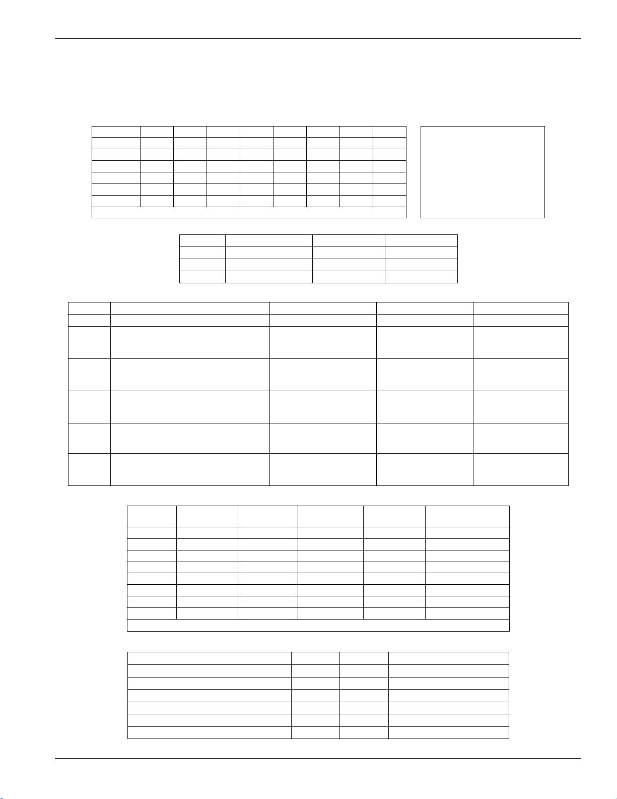
Appendix E: Template Programming
Appendix E: Template Programming
Template programming allows quick programming of the minimum functions required for basic operation. The below tables are used to determine the desired template to
be used (for information on performing template programming see Section 4 – Programming Descriptions). Each digit represents 1 of the template sections listed below.
The option number selected for each digit will make up the 5 digit template programming code.
• Digit 1 selects Zone 1-8 definition options
Digit 1 selects 1 of the following 6 options for zone definitions for the first 8 zones. A “0” in the digit 1 location indicates that the default settings for the first
8 zones are in place unless overridden. See Sections [001] to [004] on pages 30-31 for defaults.
Option Zn1 Zn2 Zn3 Zn4 Zn5 Zn6 Zn7 Zn8 1 Delay 1
1 13334444
2 13355558
3 13355557
4 11333333
5 13365555
6 13365558
Refer to Section 4 for Zone definition details 8 Standard 24-Hour Fire
• Digit 2 selects system EOL configuration options
Option [013] Opt 1 [013] Opt 2
1 NC Loops ON OFF
2 SEOL OFF OFF
3DEOL OFF ON
• Digit 3 selects panel communications options
Option Phone Line 1 Programming Section Phone Line 2 Programming Section
1 Disabled [380] Opt 1 OFF Disabled [380] Opt 1 OFF
SIA automatic Reporting Codes enabled [350] 1st Phone # [04]
2
Contact ID Reporting Codes enabled [350] 1st Phone # [03]
3
SIA automatic Reporting Codes enabled [350] 1st Phone #[04]
4
Contact ID Reporting Codes enabled [350] 1st Phone # [03]
5
Contact ID Reporting Codes enabled [350] 1st Phone # [03]
6
[380] Opt 1 ON
[381] Opt 3 OFF
[380] Opt 1 ON
[381] Opt 7 OFF
[380] Opt 1 ON
[381] Opt 3 OFF
[380] Opt 1 ON / Opt 7
OFF
[380] Opt 1 ON
[381] Opt 7 OFF
• Digit 4 selects reporting code configurations
Option
1
2
3
4
5
6
7
8
indicates included, Blank indicates default setting, indicates disabled
Common
Group
Selected
Troubles
Openings/
Closings
Common Group
2 Delay 2
3 Instant
4 Interior
5 Interior Stay/Away
6 Delayed Stay/Away
7 Delayed 24-Hour Fire
SIA automatic
Reporting Codes
enabled
SIA automatic
Reporting Codes
enabled
Residential Dial
Enabled
Residential Dial
Enabled
Contact ID Reporting
Codes Enabled
Zone
Restorals
[350] 2nd Phone # [XX]
[350] 2nd Phone # [XX]
[350] 2nd Phone # [06]
[350] 2nd Phone # [06]
[350] 2nd Phone # [03]
DLS/Installer
Lead In/Out
Description Phone 1 Phone 2 Sections
Set all Reporting Codes to automatic [320] - [349], [601] - [608] FF
Alarm/Restore call directions enabled
Tamper/Restore Call directions disabled
Opening/Closing Call directions disabled
Maintenance Call Directions enabled
Test Transmission Call directions disabled
63
[351][1] ON, [2] OFF
[359][1] OFF, [2] OFF
[367][1] OFF, [2] OFF
[375][1] ON, [2] OFF
[376][1] OFF, [2] OFF
Page 67
PowerSeries - PC1616/PC1832/PC1864
Selected Troubles
Trouble [345] Alarms [346] Restoral
Battery
AC Failure
Bell Circuit
Fire, Alarm
Aux PS
TLM
General System
General System Supervisory
FF = Communicate in automatic format , 00 = Disabled
Openings & Closings
Users CLOSINGS, Residential Dial Reporting codes Section
1-8
9-16
17-24
25-32
33-40
Users OPENINGS, Residential Dial Reporting codes Section
1-8
9-16
17-24
25-32
33-40
Enable Opening/Closings call directions for Phone 2
51 52 53 54 55 56 57 58 [339]
61 62 63 64 65 66 67 68 [339]
71 72 73 74 75 76 77 78 [340]
81 82 83 84 85 86 87 88 [340]
FF FF FF FF FF FF FF 98 [601]
11 12 13 14 15 16 17 18 [342]
21 22 23 24 25 26 27 28 [342]
31 32 33 34 35 36 37 38 [343]
41 42 43 44 45 46 47 48 [343]
FF FF FF FF FF FF FF 98 [605]
Zone Restorals
FF FF
00 00
FF FF
FF FF
FF FF
00 FF
00 00
FF FF
[367]
Zones Alarm Restoral Reporting Codes Section
1-64
00 = Disabled
00 00 00 00 00 00 00 00
DLS/Installer Lead IN/OUT
Miscellaneous Maintenance Reporting Codes Section
DEF DEF DEF 00 00 DEF DEF DEF DEF DEF 00 00
DEF = No change to default values, 00 = Disabled
• Digit 5 selects DLS connection options.
Option Programming Section DLS Connection/Call back setting
1 [401] Option 1 OFF
Option 3 OFF
[406] 0
2 [401] Option 1 ON
Option 3 OFF
[406] 9
3 [401] Option 1 ON
Option 3 ON
[406] 9
[324]-[327]
[347]
Double Call Disabled, Call Back Disabled
Number of rings to answer on set to 0
Double Call Enabled, Call Back Disabled
Number of rings to answer on set to 9
Double Call Enabled, Call Back Enabled
Number of rings to answer on set to 9
64
Page 68
Appendix F: Communicator Format Options
This section requires two 2-digit entries to set the communications format that is to be used for each phone number (1
per phone number). The 3rd telephone number uses the format programmed for the 1st telephone number.
Entry Communication Format
01 20 BPS, 1400 HZ handshake
02 20 BPS, 2300 HZ handshake
03 DTMF CONTACT I.D.
04 SIA FSK
05 Pager
06 Residential Dial
07 10 BPS, 1400 Hz handshake
08 10 BPS, 2300 Hz handshake
09 For Future Use
10 For Future Use
11 For Future Use
12 For Future Use
13 For Future Use
Reporting Codes
• SIA -0 is valid in Account or Rep Code (not 00 in a Reporting code though)
• ADEMCO Contact ID - 0 is not valid in Account or Rep
Code (A must be used, 10 in checksum)
• BPS Formats - 0 is not valid in Account or Rep Code (A
must be used)
• SIA - This format uses 300 Baud FSK as the communication media. The Account Code can be 4 or 6 hexadecimal
digits in length, All reporting codes must be 2 digits in
length. The SIA format will transmit a 4 (or 6) digit account
code, a 2-digit identifier code and a 2-digit reporting code.
The 2-digit identifier is pre programmed by the panel.
Contact ID
Contact ID is a specialized format that will communicate
information quickly using tones rather than pulses. In addition to sending information more quickly the format also
allows more information to be sent. For example, rather than
reporting an alarm zone 1 the Contact ID format can also
report the type of alarm, such as Entry/Exit alarm zone 1.
If Contact ID Sends Automatic Reporting Codes is
selected, the panel will automatically generate a reporting
code for each event. These identifiers are listed in Appendix
A. If the Automatic Contact ID option is not selected, reporting codes must be programmed. The 2-digit entry determines the type of alarm. The panel will automatically
generate all other information, including the zone number.
NOTE: If the Automatic Contact ID option is selected, the panel
will automatically generate all zone and access code numbers,
eliminating the need to program these items.
NOTE: The zone number for Zone Low Battery and Zone Fault
events will not be identified when Programmed Contact ID is
used.
If the Contact ID uses Automatic Reporting Codes
option is enabled, the panel will operate as follows:
• If an event’s reporting code is programmed as [00], the
panel will not attempt to call the central station.
• If the reporting code for an event is programmed as anything from [01] to [FF], the panel will automatically generate the zone or access code number. See Appendix A for
a list of the codes which will be transmitted.
If the Contact ID uses Programmed Reporting Codes
option is enabled, the panel will operate as follows:
Appendix F: Communicator Format Options
• If an event’s reporting code is programmed as [00] or [FF],
the panel will not attempt to call central station.
• If the reporting code for an event is programmed as anything from [01] to [FE], the panel will send the programmed
reporting code.
• Account numbers must be four digits.
• If the digit ‘0’ is in the account number substitute the HEX
digit ‘A’ for the ‘0’.
• All reporting codes must be two digits.
• If the digit ‘0’ is in the reporting code substitute the HEX
digit ‘A’ for the ‘0’.
• To prevent the panel from reporting an event program the
reporting code for the event as [00] or [FF].
Contact ID Sends Automatic
Reporting Codes . . . . . . . . . . . . . . . . . Section [381], Option [7]
SIA (Level 2)
SIA is a specialized format that will communicate information
quickly using frequency shift keying (FSK) rather than pulses.
The SIA format will automatically generate the type of signal
being transmitted, such as Burglary, Fire, Panic etc. The two
digit reporting code is used to identify the zone or access
code number.
If the SIA format is selected the panel can be programmed
to automatically generate all zone and access code numbers eliminating the need to program these items.
If the SIA Sends Automatic Reporting Codes option is
enabled the panel will operate as follows:
1. If the reporting code for an event is programmed as [00] the
panel will not attempt to call the central station.
2. If the reporting code for an event is programmed as anything
from [01] to [FF] the panel will AUTOMATICALLY generate
the zone or access code number.
3. Bypassed zones will always be identified when partial closing the system.
The Communicator Call Direction Options can be used to
disable reporting of events such as Openings/Closings.
Also, if all the Opening/Closing reporting codes were programmed as [00] the panel would not report.
If the SIA Sends Automatic Reporting Codes option is
disabled the panel will operate as follows:
1. If the reporting code for an event is programmed as [00] or
[FF] the panel will not attempt to call the central station.
2. If the reporting code for an event is programmed as anything
from [01] to [FE] the panel will send the programmed reporting code.
3. Bypassed zones will not be identified when partial closing
the system.
NOTE: The zone number for Zone Low Battery and Zone Fault
events will not be identified when Programmed SIA is used.
SIA Sends Automatic Reporting CodesSection [381], Option [3]
Communicator Call Direction Options . . . Section [351] to [376]
SIA Identifiers . . . . . . . . . . . . . . . . . . . . . . . . . . . . . Appendix A
Residential Dial
If Residential Dial is programmed and an event that is programmed to communicate occurs, the panel will seize the
line and dial the appropriate telephone number(s). Once the
dialing is complete, the panel will emit an ID tone and wait
for a handshake (press a 1, 2, 3, 4, 5, 6, 7, 8, 9, 0, or #
key from any telephone). It will wait for this handshake for
65
Page 69

PowerSeries - PC1616/PC1832/PC1864
the duration of Post Dial Wait for Handshake timer. Once
the panel receives the handshake, it will emit an alarm tone
over the telephone line for 20 seconds. If several alarms
occur at the same time, only one call will be made to each
telephone number the panel is programmed to call.
Communicator Call Direction Options . . . . Section [361] to [368]
Pager Format
The Communicator Format option for either telephone
number can be programmed for Pager Format. If an event
occurs and the Communicator Call Direction options
direct the call to a telephone number with the Pager Format
selected the panel will attempt to page.
When calling a pager extra digits will be required to make it
work properly.The following is a list of Hex digits and what
function they perform:
Hex [A] - not used
Hex [B] - simulates the * key on a touch tone telephone
Hex [E] - two second pause
Hex [C] - simulates the [#] key on a touch tone telephone
Hex [F] - end of telephone number marker
Hex [D] - forces the panel to search for dial tone
The panel will attempt to call the pager one time. After dialing the digits in the telephone number the panel will send
the account number and reporting code followed by the [#]
key (Hex [C]).
There is no ringback when using Pager Format. The panel
has no way of confirming if the pager was called successfully; a failure to communicate trouble will only be generated
once the maximum number of attempts has been reached.
NOTE: Do not use the digit C in a reporting code when using
Pager Format. In most cases, the digit C will be interpreted as a
[#], which will terminate the page before it has finished.
NOTE: If the panel detects a busy signal, it will attempt to page
again. It will make the maximum number of attempts programmed in section [165].
Force dialing should be disabled when using Pager format.
When using Pager format, you must program two hex digit E’s at
the end of the telephone number.
Pulse Formats
Depending on the pulse format selected the panel will communicate using the following:
• 3/1, 3/2, 4/1 or 4/2
• 1400 or 2300 Hz handshake
• 10 or 20 bits per second
• non-extended
The digit ‘0’ will send no pulses and is used as a filler. When
programming account numbers enter four digits. When programming a three digit account number the fourth digit must
be programmed as a plain ‘0’ which will act as a filler digit.
If an account number has a ‘0’ in it, substitute a HEX digit ‘A’
for the ‘0’. Examples:
• 3 digit account number [123]- program [1230]
• 3 digit account number [502] - program [5A20]
• 4 digit account number [4079] - program [4A79]
When programming reporting codes two digits must be
entered. If one digit reporting codes are to be used the second digit must be programmed as a ‘0’. If a ‘0’ is to be transmitted substitute a HEX digit ‘A’ for the ‘0’.
Examples:
• 1 digit reporting code [3] - program [30]
• 2 digit reporting code [30] - program [3A]
To prevent the panel from reporting an event program the
reporting code for the event as [00] or [FF].
Telephone Line Monitoring (TLM)
When the TLM Enable option is selected, the panel will
supervise the telephone line and will indicate a trouble condition if the telephone line is disconnected.
If the TLM Enable option is ON, the panel will check the telephone line every 10 seconds. If the telephone line voltage is
below 3V for the number of checks programmed in the TLM
Trouble Delay section, the panel will report a TLM trouble.
The default number of checks is 10. Enter a number from
(000) to (255) in the TLM Trouble Delay section to change
the number of checks before the TLM trouble is reported.
Programming a delay means that a momentary interruption
of the telephone line will not cause a trouble condition.
If the TLM Trouble Beeps When Armed option is enabled,
the panel will indicate a TLM trouble at the keypad while the
system is armed. To activate the bell output in the case of a
TLM trouble while the system is armed, the TLM Audible
(Bell) When Armed option must be selected.
When the trouble condition is restored, the panel can send a
TLM Restoral reporting code. Any events which occur while
the telephone line is down will also be communicated. If an
alternate communicator is being used, the panel can be programmed to report a TLM Trouble Reporting Code.
66
Page 70

Appendix F: Communicator Format Options
SAFETY INSTRUCTIONS FOR SERVICE PERSONNEL
WARNING: When using equipment connected to the telephone network, there are basic safety instructions that should
always be followed. Refer to the Safety Instructions provided with this product; save them for future reference. Instruct the
end-user regarding the safety precautions that shall be observed when operating this equipment.
Selecting a Suitable Location for the Alarm Controller
Use the following list as a guide to find a suitable place for this equipment:
• Locate the control panel near a telephone socket and a power outlet.
• Select a place that is free from vibration and shock.
• Place the alarm controller on a flat, stable surface and follow the installation instructions:
Do NOT locate this product where persons can walk on the secondary circuit cable(s).
Do NOT connect the alarm controller to electrical outlets on the same circuit as large appliances.
Do NOT select a place that exposes the alarm controller to direct sunlight, excessive heat, moisture, vapors, chemicals
or dust.
Do NOT install this equipment near water (e.g., bathtub, wash bowl, kitchen/laundry sink, wet basement, or near a
swimming pool).
Do NOT install this equipment and its accessories in areas where there is a risk of explosion.
Do NOT connect this alarm controller to electrical outlets controlled by wall switches or automatic timers.
AVOID sources of radio interference.
AVOID setting up the equipment near heaters, air conditioners, ventilators, and/or refrigerators.
AVOID locating this equipment close to or on top of large metal objects (e.g., metal wall studs).
Safety Precautions Required During Installation
• NEVER install this equipment and/or telephone wiring during a lightning storm.
• NEVER touch uninsulated telephone wires or terminals unless the telephone line has been disconnected at the network
interface.
• Ensure that cables are positioned so that accidents can not occur. Connected cables must not be subject to excessive
mechanical strain.
• For Direct Plug-in versions, use the transformer supplied with the device.
The power supply must be Class II, FAIL SAFE with double or reinforced insulation between the PRIMARY and
SECONDARY circuit/ENCLOSURE and be an approved type acceptable to the local authorities. All national wiring rules
shall be observed.
67
Page 71

Digital Security Controls warrants the original purchaser that for a period of twelve months from the date of purchase, the product shall be free of
defects in materials and workmanship under normal use. During the warranty period, Digital Security Controls shall, at its option, repair or
replace any defective product upon return of the product to its factory, at no charge for labour and materials. Any replacement and/or repaired
parts are warranted for the re mainder of the original warranty o r ninety (90) days, whichever is longer. The original purchase r must promptly
notify Digital Security Controls in writing that there is defect in material or workmanship, such written notice to be received in all events prior to
expiration of the warranty period. There is absolutely no warranty on software and all software products are sold as a user license under the terms
of the software license agreement included with the product. The Customer assumes all responsibility for the proper selec tion, installation,
operation and maintenance of any products purchased from DSC. Custom products are only warranted to the extent that they do not function
upon delivery. In such cases, DSC can replace or credit at its option.
International Warranty
The warranty for international customer s is the same as for any customer within Canada and the United States, with the exception th at Digital
Security Controls shall not be responsib le for any customs fees, taxes, or VAT that may be due.
Warranty Procedure
To obtain service under this warr anty, please return the item(s) in question to the point of purchase. All authorized distributors and dealers have
a warranty program. Anyone returning goods to Digital Security Controls must first obtain an authori zation number. Digital Security Controls will
not accept any shipment whatsoever for which prior authorization has not been obtained.
Conditions to Void Warranty
This warranty applies only to defects in parts and workmanship relating to normal use. It does not cover:
• damage incurred in shipping or handling;
• damage caused by disaster such as fire, flood, wind, earthquake or lightning;
• damage due to causes beyond the control of Digital Security Controls such as excessive voltage, mechanical shock or water damage;
• damage caused by unauthorized attachment, alterations, modifications or foreign objects;
• damage caused by peripherals (unless such peripherals were supplied by Digital Security Controls Ltd.);
• defects caused by failure to provide a suitable installation environment for the products;
• damage caused by use of the products for purposes other than those for which it was designed;
• damage from improper maintenance;
• damage arising out of any other abuse, mishandling or improper application of the products.
Limited Warranty
WARNING - READ CAREFULLY
Note to Installers
This warning contains vital information. As the only individual in contact with system users, it is your responsibility to bring each item in this warning to the attention
of the users of this system.
System Failures
This system has been carefully designed to be as effective as possible. There are circumstanc es, however, involving fire, burglary, or other types of emergencies
where it may not provide protection. Any alarm system of any type may be compromised deliberately or may fail to operate as expected for a variety of reasons.
Some but not all of these reasons may be:
• Inadequate Installation
A security system must be installed prope rly in order to provide adequate protection. Every installation should be evaluated by a security professional to ensure that
all access points and areas are covered. Lock s and latches on windows and doors must be secure and operate as intended. Windows, doors, walls, ceilings and
other building materials must be of sufficient strength and construction to provide the level of protection expected. A reevaluation m ust be done during and after any
construction activity. An eva luation by the fire and/or police department is highly recommended if this service is a vailable.
• Criminal Knowledge
This system contains security features which were known to be effective at the time of manufacture. It is possible for persons with cr iminal intent to deve lop
techniques which reduce the effectiveness of these features. It is important that a security system be reviewed periodically to ensure that it s features remain effe ctive
and that it be updated or replaced if it is found that it does not pro vide the protection expected.
• Access by Intruders
Intruders may enter through an unprotected access point, circumvent a sensing device, evade detection by moving through an area of insufficient coverage,
disconnect a warning device, or interfere with or prevent the proper operation of the system.
• Power Failure
Control units, intrusion detectors, smoke detectors and many other security devices require an adequate power supply for proper operation. If a device operates
from batteries, it is possible for the batteries to fail. Even if the batteries have not failed, they must be charged, in good condition and installed correctly. If a device
operates only by AC power, any interruption, however brief, will render that device inoperative wh ile it does not have power. Power interruptions of any length are
often accompanied by voltage fluctuations which may da mage electronic equipment such as a security system. After a power inter ruption has occurred,
immediately conduct a complete system test to ensure that the sy stem operates as intended.
• Failure of Replaceable Batteries
This system’s wireless transmitters have been designed t o provide several years of battery life under normal conditions. The expected battery life is a function of the
device environment, usage and type. Ambient conditions such as high humidity, high or low temperatures, or large temp erature fluctuations may reduce the
expected battery life. While each transmitting device has a low battery monitor which identifies whe n the batteries need to be replaced, this monitor may fail to operate as expected. Regular testing and maintenance will keep the system in good operat ing condition.
• Compromise of Radio Frequency (W ireless) Devices
Signals may not reach the receiver under all circumstances which could include metal objects placed on or near the radio path or deliberate jamming or other
inadvertent radio signal interference.
• System Users
A user may not be able to operate a panic or emergency switch possibly due to permanent or temporary physical disabilit y, inability to reach the device in time, or
unfamiliarity with the correct operation. It is important that all system users be trained in the correct operation of the alarm system and that they know how to respond
when the system indicates an alarm.
IMPORTANT - READ CAREFULLY: DSC Software purchased with or without Products and Components
is copyrighted and is purchased under the following license terms:
• This End-User License Agreement (“EULA”) is a legal agreement between You (the company, individual or entity who acquired the Software
and any rela ted Hardware ) and Digital Security Controls, a division of Tyco Safety Products Canada Ltd. (“DSC”), the manufacturer of the
integrated security systems and the developer of the software and any related products or components (“HARDWARE”) which You acquired.
• If the DSC software product (“SOFTWARE PRODUCT” or “SOFTWARE”) is intended to be accompanied by HARDWARE, and is NOT accompanied by new HARDWARE, You may not use, copy or install the SOFTWARE PRODUCT. The SOFTWARE PRODUCT includes computer software, and may include associated media, printed materials, and “online” or electronic documentation.
• Any software provided along with the SOFTWARE PRO DUCT that is associated with a separate end-user license agreement is licensed to You
under the terms of that license agreement.
• By installing, copying, downloading, storing, accessing or otherwise using the SOFTWARE PRODUCT, You agree unconditionally to be bound
by the terms of this EULA, even if this EULA is deemed to be a modification of any previous arrangement or contract. If You do not agree to
the terms of this EULA, DSC is unwilling to license the SOFTWARE PRODUCT to You, and You have no right to use it.
SOFTWARE PRODUCT LICENSE
The SOFTWARE PRODUCT is protected by copyright laws and international copyright treaties, as well as other intellectual property laws and
treaties. The SOFTWARE PRO DUCT is licensed, not sold.
1.GRANT OF LICENSE This EULA grants You the following rights:
(a) Software Installation and Use - For each license You acquire, You may have only one copy of the SOFTWARE PRODUCT installed.
(b) Storage/Network Use - The SOFTWARE PRODUCT may not be installed, accessed, displayed, run, shared or used concurrently on or from
different computers, including a workstation, terminal or other digital electronic device (“Device”). In other words, if You have several
workstations, You will have to acquire a license for each workstation where the SOFTWARE will be used.
(c) Bac kup Copy - You may make back-up copies of the SOFTWARE PRODUCT, but You may only have one copy per license installed at any
given time. You may use the back-up copy solely for archival purposes. Except as expressly provided in this EULA, You may not otherwise
make copies of the SOFTWARE PRODUCT, including the printed materials accompanying the SOFTWARE.
2. DESCRIPTION OF OTHER RIGHTS AND LIMITATIONS
(a) Limitations on Reverse Engineering, Decompilation and Disassembly - You may not reverse engineer, decompile, or disassemble the
SOFTWARE PRODUCT, except and only to the extent that such activity is expressly permitted by applicable law notwithstanding this
limitation. You may not make any changes or modifications to the Software, without the written permission of an officer of DSC. You may
not remove any proprietary notices, marks or labels from the Software Product. You shall institute reasonable measures to ensure
compliance with the terms and conditions of this EULA.
(b) Separation of Components - The SOFTWARE PRODUCT is licensed as a single product. Its component parts may not be separated for use
on more than one HARDWARE unit.
(c) Si ngle INTEGRATED PRODUCT - If You acquired thi s SOFTWARE with HARDWARE, then the SOFTWARE PRODUCT is licen sed with the
HARDWARE as a single integrated product. In this case, the SOFTWARE PRODUCT may only be used with the HARDWARE as set forth in
this EULA.
(d) Rental - You may not rent, lease or lend the SOFTWARE PRODUCT. You may not make it available to others or post it on a server or web
site.
(e)Software Product Transfer - You may transfer all of Your rights under this EULA only as part of a permanent sale or transfer of the HARDWARE,
provided You retain no copies, You transfer all of the SOFTWARE PRODUCT (including all component parts, the media and printed materials,
any upgrades and this EULA), and provided the recipient agrees to the terms of this EULA. If the SOFTWARE PRODUCT is an upgrade, any
transfer must also include all prior versions of the SOFTWARE PRODUCT.
Items Not Covered by Warranty
In addition to the items which void the Warranty, the following items shall not be covered by Warranty: (i) freight cost to the repair centre; (ii)
products which are not identified with DSC's product label and lot number or serial number; (iii) products disassembled or repaired in such a
manner as to adversely affect performance or prevent adequate inspection or testing to verify any warranty claim. Access cards or tags returned
for replacement under warranty will be credited or replaced at DSC's option. Products not covered by this warranty, or otherwise out of warranty
due to age, misuse, or damage shall be evaluated, and a repair estimate shall be provided. No repair work will be performed until a valid
purchase order is received from the Customer and a Return Merchandise Authorization number (RMA) is issued by DSC's Customer Service.
Digital Security Controls Ltd.’s liability for fai lure to repair the product under this warranty after a reasonable number of attempts will be limited
to a replacement of the product, as the exclusive rem edy for breach of warranty. Under no circumstances shall Digital Security Controls be liable
for any special, incidental, or consequential damages based upon breach of warranty, breach of contract, negligence, strict liability, or any other
legal theory. Such damages include, but are not limited to, loss of profits, loss of the product or any associated equipment, cost of capital, cost
of substitute or replacement equipment, facilities or services, down tim e, purchaser’s time, the claims of third parties, inclu ding customers, and
injury to property. The laws of some jurisdictions limit or do not allow the disclaimer of consequential damages. If the laws of such a jurisdiction
apply to any claim by or against DSC, the limitations and disclaimers contained here shall be to the greatest extent permitted by law. Some
states do not allow the exclusion or limitation of incidental or consequential damages, so that the above may not apply to you.
This warranty contains the entire warranty and shall be in lieu of any and all other warranties, wh ether expressed or implied (in cluding all implied
warranties of merchantability or fitness for a parti cular purpose) and of all other obligations or liabilities on the part of Digital Security Controls.
Digital Security Controls neither assumes responsibility for, nor authorizes any other person purporting to act on its behalf to modify or to
change this warranty, nor to assume for it any other warranty or liability concerning this product. This disclaimer of warranties and limited
warranty are governed by the laws of the province of Ontario, Canada.
WARNING: Digital Security Controls recommends that the entire system be completely tested on a regular basis. However, despite
frequent testing, and due to, but not limited to, criminal tampering or electrical disruption, it is possible for this product to fail to perform
as expected.
Digital Security Controls will at its option repair or replace out-of-warranty products which are returned to its factory according to the following
conditions. Anyone returning goods to Digital Security Controls must first obtain an authorization number. Digital Security Controls will not
accept any shipment whatsoever for which prior authorization has not been obtained.
Products which Digital Security Controls determines to be repairable will be repaired a nd returned. A set fee which Digital Security Controls has
predetermined and which may be revised from time to time, will be charged for each unit repaired.
• Smoke Detectors
Smoke detectors that are a part of this system may not properly alert occupants of a fire for a number of reasons, some of which follow. The smoke detectors may
have been improperly installed or positioned. Smoke may not be able to reach the smoke detectors, such as when the fire is in a chimney, walls or roofs, or on the
other side of closed doors. Smoke detec tors may not detect smoke from fires on another level of the r esidence or building.
Every fire is different in the amount of smoke produced and the rate of burning. Smoke detectors cannot sense all types of fires equally well. Smoke detectors may
not provide timely warning of fires caused by c arelessness or safety hazards such as smoking in bed, violent explosions, escaping gas, impro per storage of
flammable materials, overloaded electrical circuits, children playing with matches or arson.
Even if the smoke detector operates as intended, the re may be circumstances when there is insufficient warning to allow all occupants to escape in time to avoid
injury or death.
• Motion Detectors
Motion detectors can only detect motion within the designated areas as shown in their respective installation instructions. They cannot discriminate between
intruders and intended occupants. Motion dete ctors do not provide volumetric area protection. They have multiple beams of detection and motion can only be
detected in unobstructed areas covered by these beam s. They cannot detect motion which occu rs behind walls, ceilings, floo r, closed doors, glass partitions, glass
doors or windows. Any type of tampering whether intentional or unintentional such as masking, painting, or sp raying of any material on the lenses, mirrors, window s
or any other part of the detection system will impair its proper operation.
Passive infrared motion de tectors operate by sensing changes in temperature. However their effectiveness can be reduced when th
or above body temperature or if there are intentional or unintentional sources of heat in or nea r the detection area. Some of these heat sources could be heaters,
radiators, stoves, barbeques, fireplaces, sunlight, steam vents, lighting and so on.
• Warning Devices
Warning devices such as sirens, bells, horns, or strobes may not warn peopl e or waken someone sleepin g if there is an intervening wall or door. If warning devices
are located on a different level of the residence or premise, then it is less likely that the occupants will be alerted or awakened. Audible warning devices ma y be
interfered with by other noise sources such as stereos, radios, televisions, air conditioners or other appliances, or passing traffic. Audible warning devices, however
loud, may not be heard by a hearing-impaired person.
• Telephone Lines
If telephone lines are used to transmit alarms, they may be out of service or busy for certain periods of time. Also an intruder may cut the telephone line or defeat its
operation by more sophisticated means which may be difficult to de tect.
• Insufficient Time
There may be circumstances when the system will operate as intended, yet the o ccupants will not be protected from the emergency due to their inability to respond
to the warnings in a timely manner. If the system is monitored, the response may not occur in time to protect the occupants or their belongings.
• Component Failure
Although every effort has been made to make this system as reliable as possible, the system may fail to function as intended due to the failure of a component.
• Inadequate Testing
Most problems that would prevent an alarm system from operating as intended can be found by regular testing and maintenance. The complete system shoul d be
tested weekly and immediately after a break-i n, an attempted break-in, a fire, a storm, an earthquake, an accident, or any kind of construction activity inside or
outside the premises. The testing should include all sensing devices, keypads, consoles, alarm indicating devices and any other operat ional devices that are part of
the system.
•Security and Insurance
Regardless of its capabilities, an alarm system is not a subs titute for property or life insurance. An alarm system also is not a substitute for property owners, renters,
or other occupants to act prudently to prevent or minimize the harmful effects of an emergency situation.
(f) Termination - Without prejudice to any other rights, DSC may terminate t his EULA if You fail to comply with the terms and conditions of this
EULA. In such event, You must destroy all copies of the SOFTWARE PRODUCT and all of its component parts.
(g) Trademarks - This EULA does not grant You any rights in connection with any trademarks or service marks of DSC or its suppliers.
3. COPYRIGHT - All title and intellectual property rights in and to the SOFTWARE PRODUCT (including but not limited to any images,
photographs, and text incorporated into the SOFTWARE PRODUCT), the accompanying printed materials, and any copies of the SOFTWARE
PRODUCT, are owned by DSC or its suppliers. You may not copy the printed materials accompanying the SOFTWARE PRODUCT. All title and
intellectual property rights in and to the content which may be accessed through use of the SOFTWARE PRODUCT are the property of the
respective content owner and may be protected by applicable copyright or other intellectual property laws and treaties. This EULA grants You no
rights to use such content. All rights not expressly granted under this EULA are reserved by DSC and its suppliers.
4. EXPORT RESTRIC TIONS - You agree that You will not export or re-export the SOFTWARE PRODUCT to any country, person, or entity
subject to Canadian export restrictions.
5. CHOICE OF LAW -
6. ARBITRATION - All disputes arising in connection with th is Agreement shall be determined by final and binding arbitration in accordance
with the Arbitration Act, and the parties agree to be bound by the arbitrator’s decision. The place of arbitration shall be Toronto, Canada, and the
language of the arbitration shall be English.
7. LIMITED WARRANTY
(a) NO WARRANTY - DSC PROVIDES THE SOFTWARE “AS IS” WITHOUT WARRANTY. DSC DOES NOT WARRANT THAT THE SOFTWARE WILL MEET
YOUR REQUIREMENTS OR THAT OPERATION OF THE SOFTWARE WILL BE UNINTERRUPTED OR ERROR-FREE.
(b) CHANGES IN OPERATING ENVIRONMENT - DSC shall not be responsible for problems caused by changes in the operating characteristics
of the HARDWARE, or for problems in the interaction of the SOFTWARE PRODUCT with non-DSC-SOFTWARE or HARDWARE PRODUCTS.
(c) LIMITATION OF LIABI LITY; WARRANTY REFLEC TS ALLOCATION OF RISK - IN ANY EVENT, IF ANY ST ATUTE IMPLIES WARRANTIES OR
CONDITIONS NOT STATED IN THIS LICENSE AGREEMENT, DSC’S ENTIRE LIABILITY UNDER ANY PROVISION OF THIS LICENSE
AGREEMENT SHALL BE LIMI TED TO THE GREATER OF THE AMOUNT ACTUALLY PAID B Y YOU TO LICENSE THE SOFT WARE PRODUCT
AND FIVE CANADIAN DOLLARS (CAD$5.00). BECAUSE SOME JURISDICTIONS D O NOT ALLOW THE EXCLUSION OR LI MITATION OF
LIABILITY FOR CONSEQUENTIAL OR INCIDENTAL DAMAGES, THE ABOVE LIMITATION MAY NOT APPLY TO YOU.
(d) DISCLAIMER OF WARRANTIES - THIS WARRANTY CONTAINS THE ENTIRE WARRANTY AND SHALL BE IN LIEU OF ANY AND ALL OTHER
WARRANTIES, WHETHER EXPRESSED OR IMPLIED (INCLUDING ALL IMPLIED WARRANTIES OF MERCHANTABILITY OR FITNESS FOR A
PARTICULAR PURPOSE) AND OF ALL OTHER OBLIGATIONS OR LIABILITIES ON THE PART OF DSC. DSC MAKES NO OTHER
WARRANTIES. DSC NEITHER ASSUMES NOR AUTHORIZES ANY OTHER PERSON PURPORTING TO ACT ON ITS BEHALF TO MODIFY OR
TO CHANGE THIS WARRANTY, NOR TO ASSUME FOR IT ANY OTHER WARRANTY OR LIABILITY CONCERNING THIS SOFTWARE
PRODUCT.
(e) EXCLUSIVE REMEDY AND LIMITATION OF WARRANTY - UNDER NO CIRCUMSTANCES SHALL DSC BE LIABLE FOR ANY SPECIAL,
This Software License Agreemen t is governed by the laws of the Province of Ontario, Canad a.
INCIDENTAL, CONSEQUENTIAL OR INDIRECT DAMAGES BASED UPON BREACH OF WARRANTY, BREACH OF CONTRACT,
NEGLIGENCE, STRICT LIABILITY, OR ANY OTHER LEGAL THEORY. SUCH DAMAGES INCLU DE, BUT ARE NOT LIMITED TO,
LOSS OF PROFITS, LOSS OF THE SOFTWARE PRODUCT OR ANY ASSOCIATED EQUIPMENT, COST OF CAPITAL, COST OF
SUBSTITUTE OR REPLACEMENT EQUIPMENT, FACILITIE S OR SERVICES, DOWN TIME, PURCHASERS TIME, THE CLAIMS OF
THIRD PARTIES, INCLUDING CUSTOMERS, AND INJURY TO PROPERTY.
WARNING: DSC recommends that the entire system be completely tested on a regular basis. However, despite frequent
testing, and due to, but not limited to , criminal tampering or electrical di sruption, it is possible for this SOF TWARE
PRODUCT to fail to perform as ex pected.
Disclaimer of Warranties
Out of Warranty Repairs
e ambient temperature rises near
Page 72
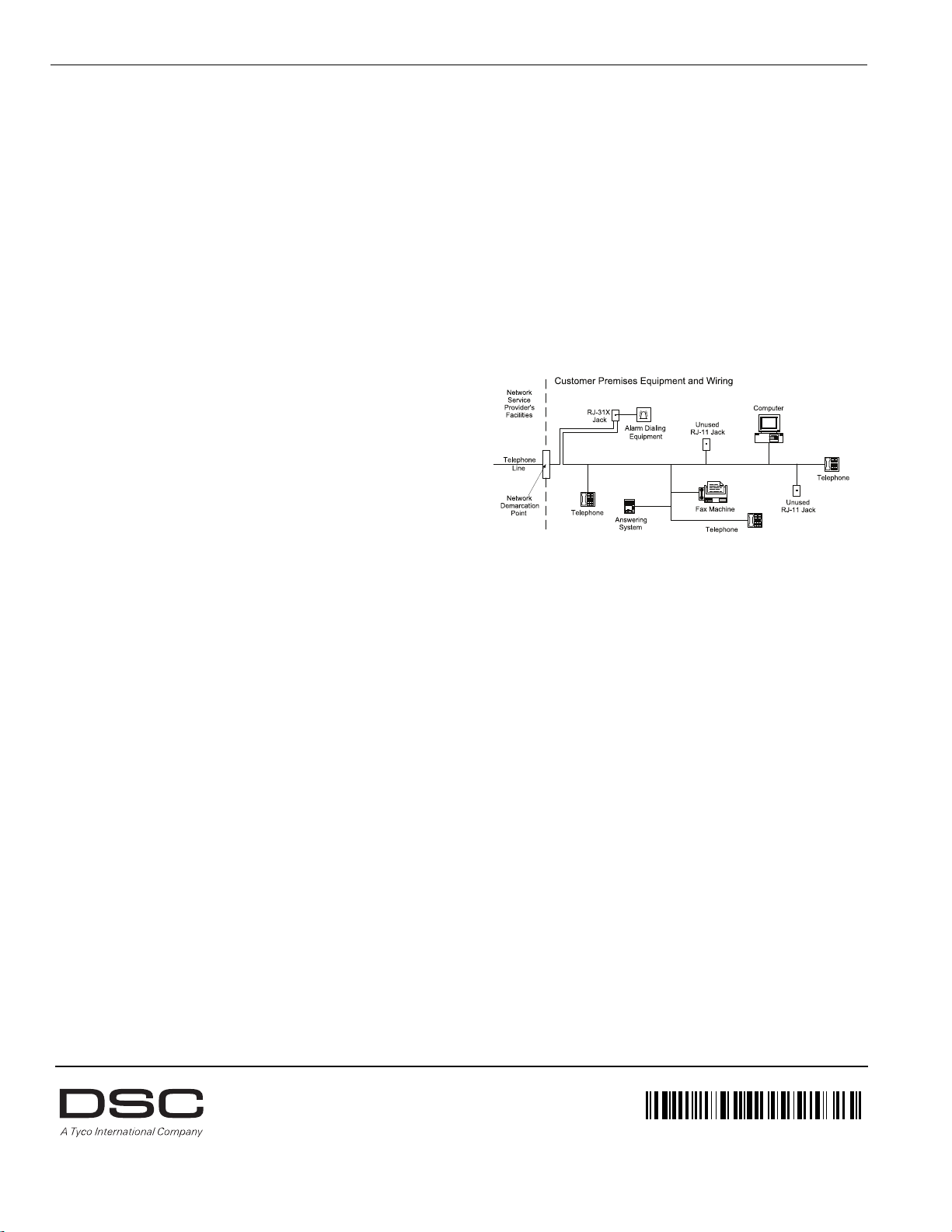
FCC COMPLIANCE STATEMENT
29008247R002
NOTE: CAUTION: Changes or modifications not expressly
approved by Digital Security Controls could void your authority to
use this equipment.
This equipment has been tested and found to comply with the limits for a Class B digital device, pursuant to Part 15 of the FCC Rules. These limits are designed to provide reasonable
protection against harmful interference in a residential installation. This equipment generates,
uses and can radiate radio frequency energy and, if not installed and used in accordance with
the instructions, may cause harmful interference to radio communications. However, there is
no guarantee that interference will not occur in a particular installation. If thi s equipment does
cause harmful interference to radio or television reception, which can be deter-mined by turning the equipment off and on, the user is encouraged to try to correct the interference by one
or more of the following measures:
• Re-orient the receiving antenna.
• Increase the separation between the equipment and receiver.
• Connect the equipment into an outlet on a circuit different from that to which the
receiver is connected.
• Consult the dealer or an experienced radio/television technician for help.
The user may find the following booklet prepared by the FCC useful: "How to Identify and
Resolve Radio/Television Interference Problems". This booklet is available from the U.S.
Government Printing Office, Washington D.C. 20402, Stock # 004-000-00345-4.
IMPORTANT INFORMATION
This equipment complies with Part 68 of the FCC Rules. On the side of this equipment is
a label that contains, among other information, the FCC registration number and ringer
equivalence number (REN) for this equipment. If requested, this number must be provided
to the Telephone Company.
PC1864 Product Identifier US: F53AL01BPC1864
PC1832 Product Identifier US: F53AL01BPC1832
PC1616 Product Identifier US: F53AL01BPC1614
REN: 0.1B
USOC Jack: RJ-31X
Telephone Connection Requirements
A plug and jack used to connect this equipment to the premises wiring and telephone network must comply with the applicable FCC Part 68 rules and requirements adopted by the
ACTA. A compliant telephone cord and modular plug is provided with this product. It is
designed to be connected to a compatible modular jack that is also compliant. See installation instructions for details.
Ringer Equivalence Number (REN)
The REN is used to determine the number of devices that may be connected to a telephone
line. Excessive RENs on a telephone line may result in the devices not ringing in response to
an incoming call.
In most but not all areas, the sum of RENs should not exceed five (5.0). To be certain of the
number of devices that may be connected to a line, as determined by the total RENs, contact
the local Telephone Company. For products approved after July 23, 2001, the REN for this
product is part of the product identifier that has the format.
US: AAAEQ##TXXXX. The digits represented by ## are the REN without a decimal point
(e.g., 03 is a REN of 0.3). For earlier products, the REN is separately shown on the label.
Incidence of Harm
If this equipment PC1864/PC1832/PC1616 causes harm to the telephone network, the telephone company will notify you in advance that temporary discontinuance of service may
be required. But if advance notice is not practical, the Telephone Company will notify the
customer as soon as possible. Also, you will be advised of your right to file a complaint
with the FCC if you believe it is necessary.
Changes in Telephone Company Equipment or Facilities
The Telephone Company may make changes in its facilities, equipment, operations or procedures that could affect the operation of the equipment. If this happens the Telephone
Company will provide advance notice in order for you to make necessary modifications to
maintain uninterrupted service.
Equipment Maintenance Facility
If trouble is experienced with this equipment PC1616, PC1832, PC1864 for repair or warranty information, please contact the facility indicated below. If the equipment is causing
harm to the telephone network, the Telephone Company may request that you disconnect
the equipment until the problem is solved. This equipment is of a type that is not intended
to be repaired by the end user.
DSC c/o APL Logistics, 757 Douglas Hill Rd., Lithia Springs, GA 30122
Additional Information
Connection to party line service is subject to state tariffs. Contact the state public utility
commission, public service commission or corporation commission for information.
Alarm dialling equipment must be able to seize the telephone line and place a call in an
emergency situation. It must be able to do this even if other equipment (telephone, answering system, computer modem, etc.) already has the telephone line in use. To do so, alarm
dialling equipment must be connected to a properly installed RJ-31X jack that is electrically in series with and ahead of all oth er equipment attached to the same telephone line. Proper installation is depicted in the figure below. If you have any questions concerning these
instructions, you should consult your telephone company or a qualified installer about installing the RJ-31X jack and alarm dialling equipment for you.
INDUSTRY CANADA STATEMENT
NOTICE: This Equipment meets the applicable Industry Canada Terminal Equipment Technical Specifications. This is confirmed by the registration number. The abbreviation, IC, before the registration number signifies that registration was performed based on a Declaration
of Conformity indicating that Industry Canada technical specifications were met. It does not
imply that Industry Canada approved the equipment.
NOTICE: The Ringer Equivalence Number (REN) for this terminal equipment is 0.1. The
REN assigned to each terminal equipment provides an indication of the maximum number of
terminals allowed to be connected to a telephone interface. The termination on an interface
may consist of any combination of devices subject only to the requirement that the sum of the
Ringer Equivalence Numbers of all devices does not exceed five.
PC1616 Registration numberIC: 160A-PC1614
PC1832 Registration numberIC: 160A-PC1832
PC1864 Registration numberIC: 160A-PC1864
This Class B digital apparatus meets all requirements of the Canadian interference-causing equipment regulations.
Cet appareil numérique de la Classe B respecte toutes les exigences de règlement sur le
materiel brouilleur du Canada.
The trademarks, logos, and service marks displayed on this document are registered in the United States [or other countries]. Any misuse of the
trademarks is strictly prohibited and Tyco International Ltd. will aggressively enforce its intellectual property rights to the fullest extent of the law,
including pursuit of criminal prosecution wherever necessary. All trademarks not owned by Tyco International Ltd. are the property of their respective
owners, and are used with permission or allowed under applicable laws.
Product offerings and specifications are subject to change without notice. Actual products may vary from photos. Not all products include all
features. Availability varies by region; contact your sales representative.
© 2012 Tyco International Ltd. and its Respective Companies.
All Rights Reserved.
Tech Support: 1-800-387-3630 (Canada & U.S.) or 905-760-3000
Printed in Canada • www.dsc.com
 Loading...