

Page 1
HS2LED/HS2ICN(P)(RF)x/HS2LCD(RF)(P)x v1.0
Installation Instructions, Instructions d’Installation, Instrucciones de instalación,
Instruções de Instalação
English, Français, Español, Português
WARNING: Refer to the PowerSeries Neo Reference manual for information on limitations regarding product use and function, and information on the limitations as to the liability of the manufacturer.
NOTE: These instructions must be used in conjunction with the system installation manual of the control panel with which this equipment is intended to be used. This installation sheet applies to the fol-
lowing models: HS2LED, HS2ICN, HS2ICNP, HS2ICNRFx, HS2ICNRFPx, HS2LCD, HS2LCDP, HS2LCDRFx and HS2LCDRFPx; x = 9 where the system operates in 912-919MHz, 8 where the
system operates in 868MHz band, and 4 where the system operates in 433MHz band. The Model HS2LED, HS2LCD(P), HS2ICN(P), HS2LCDRF(P)8, HS2ICNRF(P)8 keypads have been certified by
Telefication according to EN50131-1:2006 + A1:2009, EN50131-3:2009 for Grade 2, Class II.
Page 2
Installation Instructions
The HS2LED/HS2ICN(P)(RF)x/HS2LCD(RF)(P)x keypads are
compatible with the PowerSeries Neo HS2016/32/64, HS20144* and HS2128 panels. The RF keypads combine a wireless
transceiver with the respective HS2 keypad.
* Model not UL/ULC listed.
Specifications
• Temperature range: -10°C to +55°C (14°F to 131°F); Temperature range for UL/ULC: 0°C to +49°C (32°F to 120°F)
• Humidity (MAX): 93%R.H. non-condensing
• Plastic enclosure protection degree: IP30, IK04
• Voltage rating: 13.8V
compatible control panel)
• Connects to control panel Corbus via 4 wires
• 1 configurable zone input or PGM output*
• HS2LED/ HS2ICN(P)/HS2LCD(P)/HS2ICNRF(P)/
HS2LCDRF(P) Current draw:55mA(min)/105mA(max)
• Wall-mount tamper
• 5 programmable function keys
• Ready (Green LED), Armed (Red LED), Trouble (Yellow
LED), AC (Green LED)
• Dimensions (L x W x D): 168mm x 122mm x 20 mm
• Weight: 260g
• Low temperature sensor
• Frequency: 433 MHz (HS2ICNRF4/HS2LCDRF4)
• 868 MHz (HS2ICNRF8/HS2LCDRF8)
• 912-919MHz (HS2ICNRF9/HS2LCDRF9)
• Up to 128 wireless zones
* Zone not to be programmed as Fire type or 24h type.
NOTE: Keypads contain no serviceable parts.
NOTE: Only models operating in band 912-919MHz are UL/
ULC listed.
Unpack
The keypad package includes the following:
HS2LED/ICN(RF)/
LCD(RF)
• 1 keypad • 1 keypad
• 4 mounting screws • 4 mounting screws
• 2 end-of-line resistors • 2 end-of-line resistors
• Keypad inner door
labels
• 1 tamper switch • 1 tamper switch
DC nominal (power provided by the
HS2ICN(RF)P/LCD(RF)P
• Keypad inner door labels
• Installation Instructions • Installation Instructions
Table 1: Compatible Devices
Wireless PG smoke detector
Wireless PG smoke and heat detector
• Mini Proximity (prox) tag
(MPT)
UL
PGx926
UL
PGx916
Wireless PG CO detector PGx913
Wireless PG PIR motion detector PGx904(P)
Wireless PG PIR + camera motion detector
Wireless PG curtain motion detector
PGx934(P)
PGx924
UL
Wireless PG dual tech motion detector PGx984(P)
Wireless PG mirror motion detector PGx974(P)
Wireless PG outdoor motion detector
Wireless PG glass break detector PGx912
Wireless PG shock detector
Wireless PG flood detector
Wireless PG temperature detector (indoor)
Outdoor temperature probe (requires PGx905) PGTEMP-
Wireless PG key
Wireless PG key
Wireless PG panic key
Wireless PG 2-button key PGx949
Wireless PG indoor siren PGx901
Wireless PG outdoor siren
Wireless PG repeater
Wireless PG door/window contact
Wireless PG door/window contact w/AUX PGx945
NOTE: In this chart, x in the model number represents the
operating frequency of the device as follows: 9 (912-919 MHz),
8 (868MHz), 4 (433MHz).
NOTE: Only models operating in the band 912-919 MHz are
UL/ULC or cUL listed where indicated. Only UL approved
devices are to be used with UL/ULC listed systems.
Mount
Mount the keypad where it is accessible to designated points of
entry and exit. Once a dry and secure location is selected, perform the following steps to mount the keypad.
PGx994
PGx935
PGx985
PGx905
PROBE
PGx939
PGx929
PGx938
PGx911
PGx920
PGx975
UL
UL
UL
UL
UL
UL
UL
UL
UL
UL
UL
UL
UL
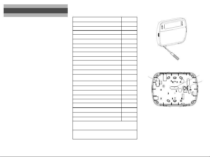
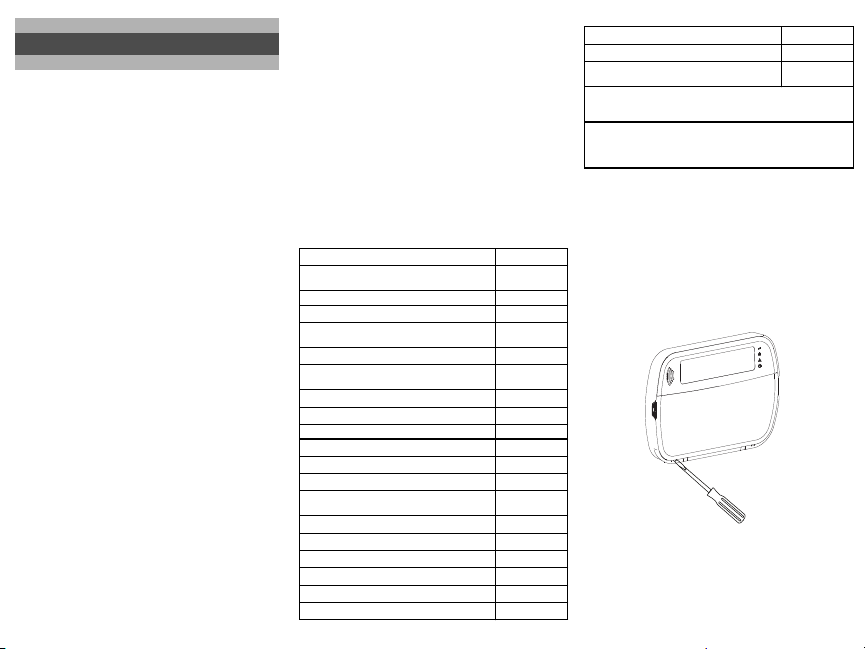
Disassemble Keypad
1. Insert the tip of a flat-head screwdriver into the slots at the
bottom left and right of the keypad.
2. Gently pry open the faceplate. This will remove it and allow
access for mounting.
UL
UL
UL
Mount and Wire Keypad
latchlatch
mounting holes
wiring slot
1. Secure keypad to wall using mounting holes. Use all four
screws provided unless mounting on a single gang box. Use
the plastic anchors supplied if the unit is to be mounted on
drywall.
2. If using the keypad tamper, secure the tamper plate to the
wall with a screw.
NOTE: For UL/ULC listed commercial burglary installations,
the use of the keypad tamper is mandatory.
3. Run wire through wiring slot or knockouts. Connect Corbus
and PGM/Zone wiring to keypad. Place tamper switch into
tamper hole on backplate.
4. Place keypad into backplate, ensuring the wire is pushed
back into the wall as much as possible. Route the wire inside
the keypad, ensuring high components are avoided. Snap the
front assembly closed, ensuring that there is no pressure to
the keypad from the wire below.
mounting holes
knockout
tamper
Page 3
NOTE: If any tension is found between the front keypad assem-
bly and the wiring, open the keypad, reroute the wire and close
again. Repeat these steps until the keypad is closed properly.
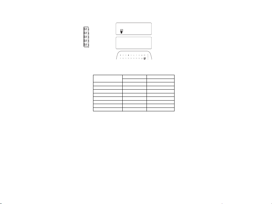
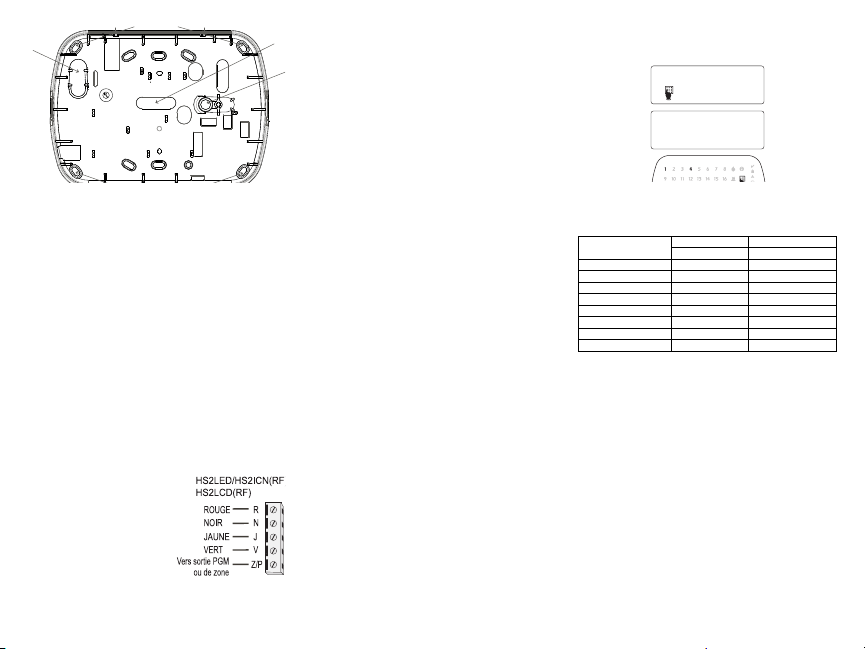
Wiring
1. Before wiring the unit, ensure
that all power (AC transformer and battery) is disconnected from the control panel.
2. Connect the four Corbus wires
from the control panel (red,
black, yellow and green) to
the keypad terminals. Refer to
the diagram:
3. If programmed as an input, a
device - such as a door contact
- may be connected to the ‘P/Z’ terminal of the keypad. This
eliminates the need to run wires back to the control panel for
the device. To connect the zone, run one wire from the device
to the ‘P/Z’ terminal and the other wire from the device to the
B (black) terminal. For powered devices, run the red wire to
the R (positive) terminal and the black wire to the B (negative) terminal. When using end of line supervision, connect
the zone according to one of the configurations described in
the PowerSeries Neo Reference manual.
NOTE: For UL/ULC installations, the zone input is a supervised
type (SEOL/DEOL). The supervision resistor is 5600Ω. If no EOL
supervision is used, there is a three foot maximum distance
required for the connected device. Use only in conjunction with
UL/ULC listed devices.
NOTE: This initiating device connected to this input contact is
not to be used for medical or fire applications.
4. If the ‘P/Z’ terminal is programmed as an output, a small
relay (such as DSC model RM-1 or RM-2) or buzzer or other
DC operated device may be connected between the positive
supply voltage and the ‘P/Z’ terminal (max.load is 50mA).
NOTE: For UL/ULC-listed installations, use UL/ULC listed
devices.
Apply Power
Once all wiring is complete, and the equipment is secured to the
building structure with at least two screws, apply power to the
control panel:
1. Connect the battery leads to the battery.
2. Connect the AC transformer.
For more information on control panel power specifications, see
the PowerSeries Neo Reference manual.
Program the Keypad
1. Press [*][8][Installer Code].
2. Use the [<][>] keys to navigate through the menus or jump
directly to a specific section by entering the section number.
Programming consists of toggling on and off options in each section or by populating data fields. Toggle options are enabled or
disabled by pressing the corresponding number on the keypad.
For example, to enable toggle options 1 and 4, press the [1] and
[4] keys. All enabled options are displayed (see the following diagram).
HS2LED/HS2ICN(RF)/
HS2LCD(RF)
________
RED R
____
BLK B
____
YEL Y
____
GRN G
____
To zone or P/Z
PGM output
1. To input data, use the [<][>] keys to select a character then
press the keypad button for the number/letter.
2. Using the [<][>] keys, scroll to the next character and repeat
the procedure. For information on entering HEX data, refer to
the PowerSeries Neo Reference manual.
Language Programming
Enter [000][000]. Enter the two-digit number corresponding to the
language desired:
Table 2: Languages
01 = English
(default)
02 = Spanish 12 = Norwegian 22 = Bulgarian
03 = Portuguese 13 = Danish 23 = Latvian
04 = French 14 = Hebrew 24 = Lithuanian
05 = Italian 15 = Greek 25 = Ukrainian
06 = Dutch 16 = Turkish 26 = Slovak
07 = Polish 17 = FFU 27 = Serbian
08 = Czech 18 = Croatian 28 = Estonian
09 = Finnish 19 = Hungarian 29 = Slovenian
Enroll the Keypad
Keypads can be enrolled automatically or manually. In either case,
the serial number of the device is used as an identifier.
NOTE: If there is no keypad enrolled on the system, once you
power up, the keypad will display the message: Press any key to
enroll. Other keypads can then be enrolled from the first keypad.
Use one of the following enrollment options:
[902][000] Auto Enroll
When this mode is selected, the total number of keypads currently
enrolled is displayed on the keypad.
1. Enter [902][000] to begin the auto-enrollment of new keypads. As each device is enrolled, the keypad displays the
model type, serial number and slot assignment. Keypads are
assigned to the next available slot.
[902][001] Manual Enroll
To manually enroll individual keypads:
1. Enter [902][001] or use the [<][>] keys and press [*].
2. When prompted, enter the serial number of the keypad found
on the back of the device.
3. An error tone is sounded if an invalid serial number is
received. Once enrolled, the device model, serial number and
slot assignment are displayed. Keypads are enrolled into the
next available slot for the device. The slot assignment can be
changed using the [<][>] keys.
4. To cancel the enrollment of a module, press [#].
41
Toggle (X) <>
“Toggle name” Y/N
10 = German 20 = Romanian
11 = Swedish 21 = Russian
NOTE: Once the maximum number of devices have been
enrolled, an error tone sounds and a warning message is displayed.
[902][002] – Module Slot Assignment (LED, LCD, ICON)
This section is used to change the slot number in which a module
is enrolled. To change the slot number:
1. Enter [902][002] or use the [<][>] keys and press [*].
2. Enter the serial number of the module.
3. When prompted, enter the new two-digit slot number. The
previous slot assignment is replaced with the new one. An
error tone sounds if an invalid slot number is entered.
[902][003] – Module Slot Assignment (LCD Keypad
Only)
Similarly to [002], this section is also used to change the slot number of a module. With this option, however, the serial number is
not required. To change the slot number:
1. Enter [902][003] or the use the [<][>] keys and press [*].
2. Use the [<][>] keys to locate the module then press [*] to
select.
3. Enter the new two-digit slot number. The previous slot
assignment is replaced with the new one. An error tone
sounds if an invalid slot number is entered.
[902][101] Unenroll Keypads
1. Enter [902][101] or use the [<][>] keys and press [*].
2. Use the [<][>] keys to scroll to the specific keypad to delete.
3. Press [*] to select the module and when prompted, press [*]
again to delete it.
[903][101] Confirm Keypad
To confirm the enrollment of individual keypads and to locate
them physically:
1. Enter [903][101] or use the [<][>] and press [*].
2. Use the [<][>] keys to scroll to the applicable keypad. The
module’s serial number and slot number are displayed on the
keypad and the status LEDs on the device flash.
3. To confirm the keypad, press [*]. If communication with a
module is lost at the time of confirmation, a warning message
is displayed for 1 second before exiting the section.
Assign a Partition to the Keypad
The keypad must be assigned to a partition if supervision or keypad zones are required. Keypad assignments and keypad option
programming must be done at each keypad individually.
At each keypad installed on the system:
1. Press [*][8][Installer Code].
2. Enter [861]-[876]for Keypad Programming and Keypad Partition Mask, corresponding to keypads 1-16.
3. Press [*] for partition assignment.
4. Enter 01 to 08 for partition assignment or use the [<][>] keys
to scroll to the specific partition If partitioning is not used,
enter [01]. For Global keypads, enter [00].
5. Press [#] twice to exit programming.
6. Continue this procedure for each keypad until all have been
assigned to the correct partition.
Program Labels (LCD keypads only)
1. Press [*][8][Installer Code].
2. Press [*] and use the [<][>] keys to scroll to Zone Labels and
press [*] again.The first zone is displayed. Alternatively,
enter, [000][001].
Page 4
3. Use the [<][>] keys to scroll to the zone label to be programmed and press [*] or enter the zone
number (e.g., 001, for zone label 1).
4. Use the [<][>] keys to scroll to the desired character ’s location, using the [<][>] keys.
5. Enter the number of the corresponding character group until the desired character is displayed
(see the following table). Example, press the “2” key three times to enter the letter “F”. Press
the “2” key four times to enter the number “2”. Press [*], then scroll to “Save”. Press [*]
again to save the label. To delete a character, use the [<][>] keys to move the cursor under the
character, then press [0]. If any key other than [<][>] is pressed before [0], the cursor moves
one space to the right and deletes that character.
CHANGE CASE – Will toggle the next letter entries between upper case (A, B, C...) and lower
case letters (a, b, c...).
ASCII ENTRY – Used to enter uncommon characters. Valid entries range from 000 to 255. Use the
[<][>] keys to scroll through the characters or enter a 3-digit number from 000-255. Press [*] to
enter the character into the label.
CLEAR TO END – Clears the display from the character where the cursor was located to the end of
the display.
CLEAR DISPLAY – Clears the entire label.
6. Continue from Step 2, until all labels are programmed.
Label Library
The Label Library is a database of words commonly used when programming labels. Individual
words can be combined as needed (e.g.,
mum of 14 characters. If a word will not fit on a line, scroll right until the cursor appears at the first
character of the second line and then add the word.
To program a custom label using the Label Library:
1. Press [*][8][Installer Code][000][001].
2. Enter [001] (to program the label for zone 01), or use the [<][>] keys to scroll to the Zone
Labels and then press [*]. The current label name is displayed for that zone.
3. Press [*] to open the menu.
4. Press [*] again to select the “Word Entry” option.
5. Enter the 3-digit number corresponding to a word (see Words Library) or use the [<][>] keys
to view words in the library.
6. Press [*] to select the word.
7. To add another word, repeat the previous procedures from step 3.
8. To add a space, press the right scroll key [>].
9. To clear characters, select “Clear to End” or “Clear Display” from the menu.
10.To save the current label and exit, press [#].
Broadcast LCD Labels
If more than one LCD keypad is present on the system, labels programmed on one keypad will be
broadcast to all other LCD keypads, after the change is confirmed.
Change Brightness/Contrast/Buzzer
LCD Keypads
1. Press [*][6][Master Code].
2. Use the [<][>] keys to scroll to either Bright Control, Contrast Control, or Buzzer Control.
3. Press [*] to select one of the following settings:
• Brightness/LED Bar Control: 15 backlighting levels are available.
• Contrast Control: 15 different display contrast levels are available.
• Buzzer Control: 15 different buzzer control levels are available.
4. Use the [<][>] keys to scroll to the desired setting.
[1] - A, B, C, 1 [5] - M, N, O, 5 [9] - Y, Z, 9, 0
[2] - D, E, F, 2 [6] - P, Q, R, 6 [0] - Space
[3] - G, H, I, 3 [7] - S, T, U, 7
[4] - J, K, L, 4 [8] - V, W, X, 8
[*] - Select
[#] - Escape
Front + Door). Each line of the display supports a maxi-
Keypad Programming
1. Press [*][8][Installer Code].
2. Select one of the programming options identified in the following.
[860] Keypad Slot Number
Not for programming; the two-digit slot number is displayed for informational purposes only.
[861]-[876] Keypad Programming Sections
[000] Address of Partition
A 2-digit entry is required to assign the keypad to a partition. Entering 00 assigns the keypad as
Global. Valid entries are 00-32. The default is 01.
[001]-[005] Keypad Function Key Programming
To program a function key:
1. Press [*][8][Installer Code].
2. Enter [861]-[876] for keypad programming.
3. Enter [001]-[005] for function keys 1-5 or use the [<][>] keys and press [*].
4. Enter a 2-digit number to assign a function key operation - [00]-[68]. See the following table.
5. Repeat from step 3 until all function keys are programmed.
6. Press [#] twice to exit Installer Programming.
[001]-[005] Function Key Assignment
Function Key Button
[001] Key 1
[002] Key 2
[003] Key 3
[004] Key 4
[005] Key 5
Keypad Function Keys
Refer to your system installation manual for a complete list of available function key options.
[00] - Null [21] - [*][7][1]Command Output 1
[02] - Instant Stay Arm [22] - [*][7][2]Command Output 2
[03] - Stay Arm [23] - [*][7][3]Command Output 3
[04] - Away Arm [24] - [*][7][4]Command Output 4
[05] - [*][9] No-Entry Arm [29] - Bypass Group Recall
[06] - [*][4] Chime ON/OFF [31] - Local PGM Activate
[07] - [*][6]
[----][4]
System Test
[09] - Night Arm [33] - Bypass Recall
[12] - Global Stay Arm [34] - User Programming
[13] - Global Away Arm [35] - User Functions
[14] - Global Disarming [37] - Time & Date Program
[16] - [*][0] Quick Exit [39] - Trouble Display
[17] - Arm Interior [40] - Alarm Memory
[32] - Bypass Mode
Valid
Default Function
Range
00–68
03 Stay Arm I_____I_____I
00–68
04 Away Arm I_____I_____I
00–68
06
00–68
22
00–68
16
Chime ON/
I_____I_____I
OFF
Command
I_____I_____I
Output 2
Quick
I_____I_____I
Exit
[61]-[68] - Partition Select 1-8
[011] Keypad Input/Output Programming
Zone or PGM
Number
Default
000
I_____I_____I_____I
Page 5
[012] Local PGM Output Pulse Activation Time
I_____I_____I
Minutes (00-99)
I_____I_____I
Seconds (00-99)
[021] First Keypad Options
Default Opt. ON OFF
I_____I
ON
ON
ON
ON
1 Fire Key Enabled Fire Key Disabled
I_____I
2 Medical Key Enabled Medical Key Disabled
I_____I
3 Panic Key Enabled Panic Key Disabled
I_____I
4 Display Access Code When Pro-
gramming
Display Xs When Programming Access Codes
[022] Second Keypad Options
Default Opt. ON OFF
I_____I
ON
OFF
ON
ON
OFF
ON
ON
OFF
[023] Third Keypad Options
Default Opt. ON OFF
OFF
ON
OFF
OFF
OFF
[030] Downloaded LCD Message
[031] Downloaded LCD Message Duration
Default: 000 I_____I_____I_____I (Valid entries are 000-255, 000=Unlimited Msg Display)
This number represents the number of times the downloaded message must be cleared before it is
permanently removed. This message can be cleared by pressing any key.
[041] Indoor Temperature Zone Assignment
Default: 000
1 Local Clock Display ON Local Clock Display OFF
I_____I
2 Local Clock Displays 24-hr Clock Displays AM/PM
I_____I
3 Auto Alarm Mem Scroll ON Auto Alarm Mem Scroll OFF
I_____I
4 For Future Use For Future Use
I_____I
5 Power LED Enabled Power LED Disabled
I_____I
6 Power LED Indicates AC Present ON
I_____I
7 Alarms Displayed While Armed
I_____I
8 Auto-Scroll Open Zones ON Auto-Scroll Open Zones OFF
Power LED Indicates AC Present OFF
Alarms Not Displayed While
Armed
I____I
1 Armed LED Power Save Armed LED Off in Sleep Mode
I____I
2 Keypad Status Shows Stay Arm
I____I
3 5th Terminal is Keypad PGM Output 5th Terminal is Keypad Zone Input
I____I
7
Local Display of Temperature No Local Display of Temperature
Low Temperature Warning
I____I
8
Enabled
I_____I_____I_____I_____I_____I_____I_____I_____I_____I_____I_____I_____I_____I_____I_____I_____|
I_____I_____I_____I_____I_____I_____I_____I_____I_____I_____I_____I_____I_____I_____I_____I_____|
I_____I_____I_____I
Keypad Status Shows Stay/Away
Arm
Low Temperature Warning
Disabled
(Valid entries are 000-128)
[042] Outdoor Temperature Zone Assignment
Default: 000
I_____I_____I_____I
(Valid entries are 000-128)
[101]-[228] Door Chime for Zones 1-128
The keypad can be programmed to make up to four different chime sounds for individual zones.
(e.g., for Zone 1, enter section [101], for Zone 2 enter section [102]).
I_I_I
Default: 01
Valid Entries
01 6 beeps
02 Bing-Bing tone
03 Ding-Dong tone
04 Alarm tone (4 second duration)
05 Zone name
[991] Reset Keypad Programming to Factory Defaults
1. Press [*][8][Installer Code].
2. Enter [991].
3. Use the [<][>] keys to scroll to the applicable keypad.
4. Press [*] to select the keypad.
5. Re-enter [Installer Code].
6. Press [*] to reset the selected keypad to factory defaults.
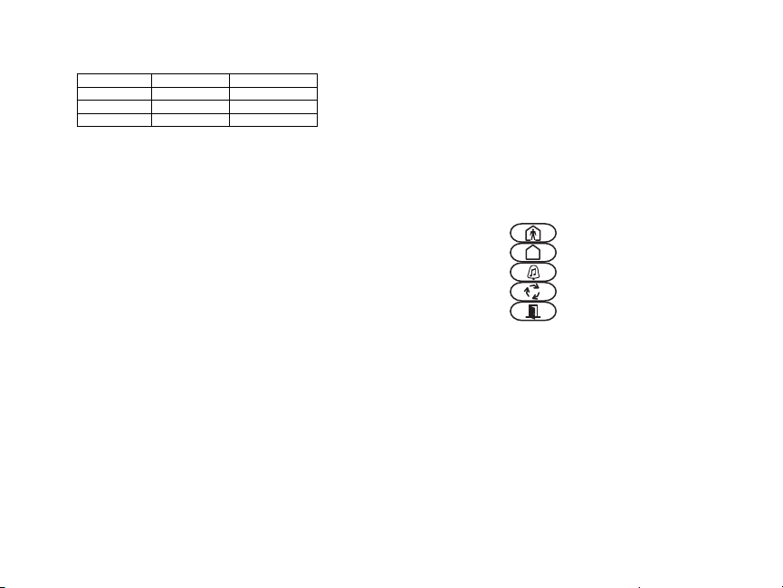
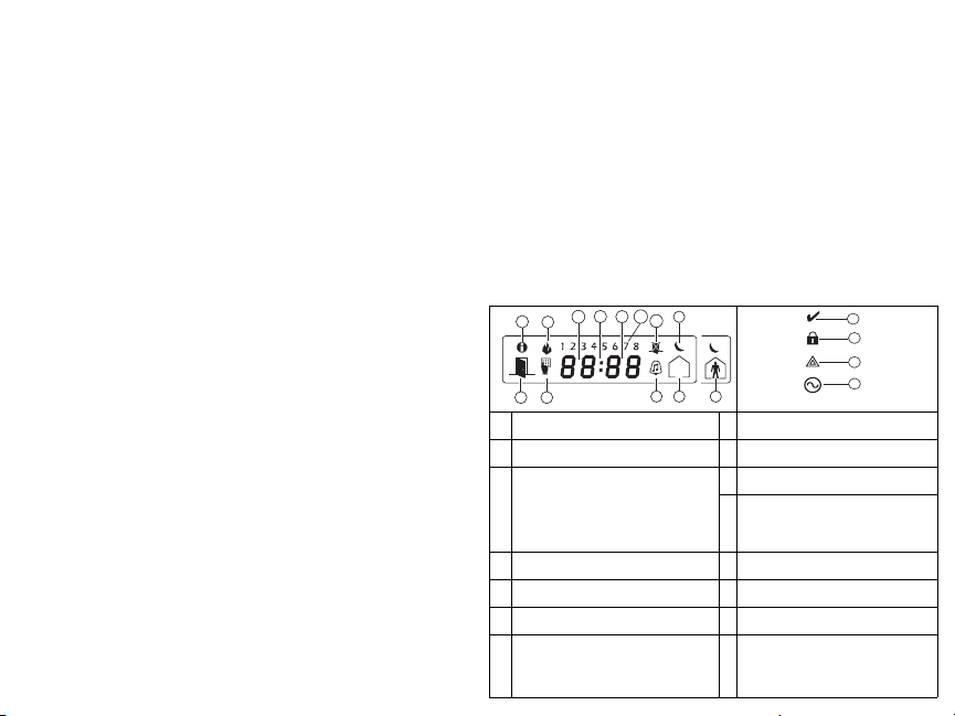
Table 3: Keypad Display Symbols
1
8
Memory – Indicates that alarms are in mem-
1
ory.
Fire – Indicates that fire alarms are in mem-
2
ory.
Clock Digits – These digits indicate the hour
and minutes when the local clock is active,
and also identify the zone when the OPEN or
3,4,
ALARM icons are active. These digits scroll
5
one zone per second from the lowest zone
number to the highest when scrolling through
zones.
1 to 8 – These numbers display toggles or dig-
6
its in binary while they are needed.
Bypass – Indicates that there are zones auto-
7
matically or manually bypassed.
Open – When zones are opened, this icon will
8
turn on and the open zones are displayed.
Program – If the system is in Installer’s or
User’s Programming, or the keypad is busy,
9
this icon flashes. If an access code is required
while accessing star menus, this LED is on
steadily to indicate that the code is required.
4
5
6
3
2
9
13
7
12
11
10
Chime – Turns on when Door Chime is ena-
10
bled and off when Door Chime is disabled.
Away – Indicates that the panel is armed in
11
away mode.
Stay – Indicates that the panel is armed in
12
stay mode.
Night – Indicates that the panel is armed in
13
night mode.
Ready Light (green) – If the Ready light is
14
on, the system is ready for arming.
Armed Light (red) – If the Armed light is
15
on, the system has been armed successfully.
System Trouble – Indicates that a system
16
trouble is active.
AC – Indicates that AC is present at the
17
main panel.
14
15
16
17
Page 6
Proximity (Prox) Tags Support (HS2ICNP/HS2ICNRFP/HS2LCDP)
The prox tag can perform any keypad function that would normally require a user access code. Present the tag to the tag reader or to the left of the keypad LCD.
Assign Proximity Tags
Using an LCD keypad:
1. Press [*][5][Master/Supervisor Code].
2. Enter a 2-digit user code.
3. Press 2.
4. Pass the enrolled tag near the tag reader on the keypad.
Delete Proximity Tags
To delete a prox tag, select the user as outlined previously.Swipe the associated prox tag. The alarm
system recognizes the tag. Press [*] to delete when prompted.
LED Bar
On the HS2ICNP/HS2ICNRFP/HS2LCDP keypads, a blue LED bar indicates that a prox tag is
approaching.
• The LED bar flashes three times when a valid prox tag is being read by the keypad.
• If the prox tag is invalid, the LED bar stays on steadily and the keypad sounds an error tone.
• The brightness of the LED bar is adjustable from the [*][6] menu. When the backlight brightness
is modified, the LED bar brightness is changed accordingly.
Downloading
The HS2LCDRF/HS2ICNRF products can be programmed over DLS V. This auto-detects the keypad type and downloads programming accordingly.
Wireless Device Setup and Programming (HS2ICNRF(P)x/HS2LCDRF(P)x)
This section describes how to enroll and program wireless devices such as contacts, motion sensors
and sirens on the alarm panel.
[804][000] Enroll Wireless Devices
1. Once the HSM2HOST is installed and enrolled on the alarm panel wireless devices can be
enrolled using the following method: Enter Installer Programming section [804][000]:
2. When prompted, either activate the device (see device installation sheet) to enroll immediately or
enter a device ID number. Do the latter to pre-enroll devices then enroll them later at the customer
site.
The alarm panel determines the type of device being enrolled and presents the appropriate programming options.
Table 4: Wireless Device Options
Device Type Programming Options
Zone
Wireless key
Siren
Repeater (01) Repeater label
3. Use the scroll keys or type in the corresponding number to select an option.
4. Scroll through the available selections, key in a number or enter text as appropriate.
5. Press [*] to accept and move to the next option.
6. Once all options are configured, the system prompts to enroll the next device.
7. Repeat the process described above until all wireless devices are enrolled.
NOTE: The configuration options listed above can be modified using [804][911] Modify Device.
[804][001]-[716] Wireless Device Configuration
To configure wireless devices:
(01) Zone type
(02) Partition assignment
(03) Zone label
(01) Partition assignment
(02) User label
(01) Partition assignment
(02) Siren label
1. Enter Installer Programming section [804] then select one of the following sub-sections:
Table 5: Wireless Zone Sub-Sections
Sub-Section Description
001-128 Configure wireless zones
551-556 Configure wireless sirens
601-632 Configure wireless keys
701-716 Configure wireless keypads
2. Select a device to configure using the scroll keys or go directly to a specific device by entering
a hotkey.
3. Use the scroll buttons or enter a hotkey to select a configuration option for the device. See
device sheets for details.
4. Press [*] to accept and move to the next option.
5. Once all options are configured, the system returns to the base configuration menu.
Repeat the process described above to configure other wireless devices.
[804][801] RF Jam Detect
RF jam detection (continuous interfering transmissions on the radio network) can be turned on or
off. When on, RF jamming is logged and reported.
To configure RF jamming:
1. Enter Installer Programming section [804][801].
2. Select one of the following options by scrolling or entering the hotkey:
Table 6: Jam Detect Options
00 Enabled/Disabled
01 UL 20/20-USA Continuous RF jamming for 20 seconds
02 EN 30/60-Europe 30 seconds of accumulated jamming within 60 seconds
03 Class 6 30/60-British
3. Press [*] to accept the selection.
4. Press [#] to exit the section.
[804][802] Wireless Supervision Window
This option is used to program the length of time a wireless device can be absent from the system
before a fault is generated.
NOTE: For EN installations, 1 hour or 2 hours must be selected.
When option 06 is used, which configures the system to generate fault conditions after a device has
been detected as absent for 24 hours, smoke detectors generate a fault condition after a maximum of
18 hours when the 200s supervision toggle option is disabled.
To program the Wireless Supervisory Window:
1. Enter Installer Programming section [804][802].
2. Select one of the following options by scrolling or entering the hotkey:
Table 7: Wireless Supervisory Window Options
00 Enabled/Disabled
01 After 1 Hour
02 After 2 Hour
03 After 4 Hour
04 After 8 Hour
05 After 12 Hour
06 After 24 Hour
3. Press [*] to accept the selection.
4. Press [#] to exit the section.
Jamming detection and reporting is enabled/disabled
Note: Must be Enabled for UL/ULC listed installations.
As EN (30/60) but reported only if the jamming duration
exceeds 5 minutes
Page 7

NOTE: For UL Residential Burglary (UL1023), Home Health Care (UL1637), ULC Residential
Burglary (ULC/ORD-C1023) installations, the maximum Supervision window shall be set to 24
hours.
For UL Residential Fire (UL985) installations, the maximum supervision window is set to 200s.
For UL Commercial Burglary (UL1610/UL365) and ULC Residential Fire (ULC-S545), the maximum supervision window shall be set to 4 hours.
[804][810] Wireless Option 1
To program wireless options:
1. Enter Installer Programming section [804][810].
2. Select one of the following options by scrolling or entering the hotkey:
Table 8: Wireless Options
01 RF Delinquency
Wireless Supervi-
02
sory/ RF Jam Alarm
03 Module Tamper
04 Fire Supervision
3. Press [*] to accept the selection and [#] to exit.
[804][841] Visual Verification Programming
To program wireless options:
1. Enter Installer Programming section [804][841].
2. Select one of the following options by scrolling or entering the hotkey:
Table 9: Visual Verification Sub-Sections
001 Visual Verification
002 View Time Window
003 View Other Alarms
[804][901]-[905] Delete Wireless Devices
To delete wireless devices:
1. Enter Installer Programming section [804] then select one of the following sub-sections:
Table 10: Module Label Sub-Sections
Sub-Section Description
901 Delete wireless zone devices
902 Delete wireless key
903 Delete sirens
On: the system cannot be armed if a wireless supervisory trouble
exists. An RF delinquency trouble is generated.
Off: wireless supervisory troubles do not prevent arming.
On: if a supervisory or jamming trouble occurs during Away arming,
the siren activates and the event is logged and reported.
Off: supervisory or RF jam troubles during Away arming do not activate the siren or get logged and reported.
On: module tampers are logged and reported.
Off: module tampers are not logged or reported.
On: fire devices are supervised every 200 seconds. If the device fails
to report within this window, a supervision trouble is generated.
Off: fire devices follow the supervision window programmed in section 802, up to a maximum of 18 hours. The supervisory window can
be programmed with a higher value, but detectors still go into fault
after 18 hours.
On: Alarms trigger image capture from PIR
Cameras
Off: Alarms do not trigger image capture
from PIR Cameras
01 Alarm + 5 Minutes
02 Alarm + 15 minutes
03 Alarm + 1 Hour
01 Fire key enabled/disabled
02 Duress key enabled/disabled
03 Medical key enabled/disabled
04 Panic key enabled/disabled
Table 10: Module Label Sub-Sections
904 Delete repeaters
905 Delete keypads
2. Select a device to delete using the scroll keys or go directly to a specific device by entering a
hotkey.
3. Press [*] to delete or [#] to exit.
[804][921]-[925] Replace Wireless Devices
Use this option to replace a faulty device enrolled on the system with another device of the same type
while maintaining the configuration of the original. The faulty device does not need to be deleted.
To replace a wireless device:
1. Enter Installer Programming section [804] then select one of the following sub-sections:
Table 11: Replace Device Sub-Sections
Sub-Section Description
921 Replace wireless zone devices
922 Replace wireless keys
923 Replace sirens
924 Replace repeater
925 Replace keypad
2. Press [*] to select a sub-section. The first available device is displayed.
3. Select a device to replace using the scroll keys or go to a specific device by entering a hotkey.
Press [*]. When prompted, activate the device (full enrollment) or enter the device ID (pre-enrollment). A message is displayed confirming enrollment.
[804][990][001 – 005] Show All Devices
Use this section to review wireless devices enrolled on the system and to view serial numbers associated with each device.
To review wireless device information:
1. Enter Installer Programming section [804][990] then select one of the following sub-sections:
• [001] – all zones
• [002] – repeaters
• [003] – sirens
• [004] – wireless keys
• [005] – keypads
2. Press [*] to select a wireless device type. The first available device is displayed.
3. Use the scroll keys to view the enrolled devices.
NOTE: This option is not fully supported by LED and ICON keypads.
[904] Placement Testing Wireless Devices
This test is used to determine RF signal status for wireless devices and can be performed at a system
keypad or at the individual device. These instructions pertain to testing at the keypad. For instructions on placement testing at the device, refer to the installation sheet provided with the wireless
equipment. The following test modes are available:
Table 12: Wireless Device Placement Test Modes
001-128 Test wireless zones Test wireless devices individually by zone.
520 Test all repeaters
550 Test all sirens
600 Test all wireless keys
Test each enrolled wireless repeater.
521-528 for repeaters 1-8
Test each enrolled wireless siren.
551-556 for sirens 1-16
Test individual wireless keys. Once in this section, press a button
on the wireless key to begin the test.
601-632 for wireless keys 1-32.
Page 8
Table 12: Wireless Device Placement Test Modes
700 Test all keypads
Two test results are provided:
• 24-hour: Average results of signal strength testing over a 24-hour period.
• Now: Signal status results of the current test.
During testing, the Ready and Armed LED's flash to indicate data is being received. A flashing
Trouble LED indicates RF interference. The following status indicators may be displayed:
Table 13: Wireless Device Status Indicators
LCD Icon* LED+ Status Repeater [905]
Strong 1 9 Strong signal strength Repeater 1
Good 2 10 Good signal strength Repeater 2
Poor 3 11 Poor signal strength Repeater 3
1-Way 4 12
Not Test 5 13
None 14
NOTE: For UL/ULC installations, only STRONG signal levels are acceptable.
*For Icon keypads, digit 1 indicates 24-hour test results; digit 2 indicates Now test results.
+For LED keypads, the first digit indicates 24-hour results; the second digit indicates Now test
results.
Troubleshooting
1. When attempting to assign a zone number to a wireless device, the keypad responds with a
long beep.
• Ensure that the keypad is properly connected to the Corbus.
2. After entering the ESN of a wireless device, then tripping it, the keypad does not indicate the
zone is open.
• Ensure the ESN has been entered correctly.
• Ensure that the zone is enabled for the partition (if partition programming is used).
• Ensure that the wireless zone is not assigned to a zone used by HSM2108 modules, an on-board
zone or a keypad zone.
• Ensure that the zone is programmed for something other than “Null Operation”. "Poor" or no
results are received from a module placement test.
• Verify that you are testing the correct zone.
• Verify that the device is in range of the keypad. Try testing the device in the same room as the
receiver.
• Confirm that the keypad is properly connected to the Corbus.
• Check that the zone is being tested correctly. Refer to the instructions that came with the device.
• Check that the batteries are working and installed correctly.
• Look for large metal objects that may be preventing the signal from reaching the keypad.
• The device must be located where consistent “Good” results are obtained. If several devices
show “Poor” results, or if panic pendants and wireless keys operate inconsistently, move the
receiver.
Test each enrolled keypad
701-716 for keypads 1-16
The device is operating in 1-way
mode only. The alarm panel cannot
configure or control the device
Displayed as the Now result if no
test was performed.
Always displayed as the 24-hour
result when testing wireless keys.
Repeater 4
Repeater 5
Repeater 6
NOTES:
Page 9

Word Library
Item # Text Item # Text Item # Text Item # Text Item # Text Item # Text
001 Aborted 042 Control 083 Garage 124 Motion 165 Shock 206 D
002 AC 043 Date 084 Gas 125 No 166 Shop 207 E
003 Access 044 Daughter’s 085 Glass 126 North 167 Side 208 F
004 Active 045 Degrees 086 Goodbye 127 Not 168 Siren 209 G
005 Activity 046 Delay 087 Gym 128 Now 169 Sliding 210 H
006 Alarm 047 Den 088 Hallway 129 Number 170 Smoke 211 I
007 All 048 Desk 089 Heat 130 Off 171 Son’s 212 J
008 AM 049 Detector 090 Hello 131 Office 172 Sound 213 K
009 Area 050 Dining 091 Help 132 OK 173 South 214 L
010 Arm 051 Disarmed 092 High 133 On 174 Special 215 M
011 Armed 052 Door 093 Home 134 Open 175 Stairs 216 N
012 Arming 053 Down 094 House 135 Opening 176 Stay 217 O
013 Attic 054 Download 095 In 136 Panic 177 Sun 218 P
014 Auxiliary 055 Downstairs 096 Install 137 Partition 178 Supervisory 219 Q
015 Away 056 Drawer 097 Interior 138 Patio 179 System 220 R
016 Baby 057 Driveway 098 Intrusion 139 Pet 180 Tamper 221 S
017 Back 058 Duct 099 Invalid 140 Phone 181 Temperature 222 T
018 Bar 059 Duress 100 Is 141 Please 182 Test 223 U
019 Basement 060 East 101 Key 142 PM 183 Time 224 V
020 Bathroom 061 Energy 102 Kids 143 Police 184 To 225 W
021 Battery 062 Enter 103 Kitchen 144 Pool 185 Touchpad 226 X
022 Bedroom 063 Entry 104 Latchkey 145 Porch 186 Trouble 227 Y
023 Bonus 064 Error 105 Laundry 146 Power 187 Unbypass 228 Z
024 Bottom 065 Exercise 106 Left 147 Press 188 Unit 229 Space
025 Breezeway 066 Exit 107 Level 148 Program 189 Up 230 ,
026 Building 067 Exterior 108 Library 149 Progress 190 West 231 027 Bus 068 Factory 109 Light 150 Quiet 191 Window 232 _ (Underscore)
028 Bypass 069 Failure 110 Lights 151 Rear 192 Zone 233 *
029 Bypassed 070 Family 111 Living 152 Receiver 193 0 234 #
030 Cabinet 071 Father’s 112 Load 153 Report 194 1 235 :
031 Canceled 072 Feature 113 Loading 154 RF 195 2 236 /
032 Car 073 Fence 114 Low 155 Right 196 3 237 ?
033 Carbon 074 Fire 115 Lower 156 Room 197 4
034 Central 075 First 116 Main 157 Safe 198 5
035 Chime 076 Floor 117 Master 158 Saver 199 6
036 Closed 077 Force 118 Mat 159 Schedule 200 7
037 Closet 078 Foyer 119 Medical 160 Screen 201 8
038 Closing 079 Freeze 120 Memory 161 Second 202 9
039 Code 080 Front 121 Menu 162 Sensor 203 A
040 Communicator 081 Furnace 122 Monoxide 163 Service 204 B
041 Computer 082 Gallery 123 Mother’s 164 Shed 205 C
Page 10

Limited Warranty
Digital Security Controls (DSC) warrants that for a period of 12 months from the date of purchase, the product shall be free of defects in materials and workmanship under normal use
and that in fulfillment of any breach of such warranty, DSC shall, at its option, repair or
replace the defective equipment upon return of the equipment to its repair depot. This warranty applies only to defects in parts and workmanship and not to damage incurred in shipping or handling, or damage due to causes beyond the control of Digital Security Controls
such as lightning, excessive voltage, mechanical shock, water damage, or damage arising
out of abuse, alteration or improper application of the equipment. The foregoing warranty
shall apply only to the original buyer, and is and shall be in lieu of any and all other warranties, whether expressed or implied and of all other obligations or liabilities on the part of Digital Security Controls. Digital Security Controls neither assumes responsibility for, nor
authorizes any other person purporting to act on its behalf to modify or to change this warranty, nor to assume for it any other warranty or liability concerning this product. In no event
shall Digital Security Controls be liable for any direct, indirect or consequential damages,
loss of anticipated profits, loss of time or any other losses incurred by the buyer in connection with the purchase, installation or operation or failure of this product. WARNING: Digital
Security Controls recommends that the entire system be completely tested on a regular
basis. However, despite frequent testing, and due to, but not limited to, criminal tampering
or electrical disruption, it is possible for this product to fail to perform as expected. IMPORTANT INFORMATION: Changes/modifications not expressly approved by DSC could void the
user’s authority to operate this equipment.
IMPORTANT - READ CAREFULLY: DSC Software purchased with or without Products and
Components is copyrighted and is purchased under the following license terms:
This End-User License Agreement (“EULA”) is a legal agreement between You (the company, individual or entity who acquired the Software and any related Hardware) and Digital
Security Controls, a division of Tyco Safety Products Canada Ltd. (“DSC”), the manufacturer
of the integrated security systems and the developer of the software and any related products
or components (“HARDWARE”) which You acquired.
If the DSC software product (“SOFTWARE PRODUCT” or “SOFTWARE”) is intended to be
accompanied by HARDWARE, and is NOT accompanied by new HARDWARE, You may not
use, copy or install the SOFTWARE PRODUCT. The SOFTWARE PRODUCT includes computer software, and may include associated media, printed materials, and “online” or electronic documentation.
Any software provided along with the Software Product that is associated with a separate
end-user license agreement is licensed to You under the terms of that license agreement.
By installing, copying, downloading, storing, accessing or otherwise using the Software
Product, You agree unconditionally to be bound by the terms of this EULA, even if this EULA
is deemed to be a modification of any previous arrangement or contract. If You do not agree
to the terms of this EULA, DSC is unwilling to license the Software Product to You, and You
have no right to use it.
SOFTWARE PRODUCT LICENSE
The SOFTWARE PRODUCT is protected by copyright laws and international copyright treaties, as well as other intellectual property laws and treaties. The SOFTWARE PRODUCT is
licensed, not sold.
1. GRANT OF LICENSE This EULA grants You the following rights:
(a) Software Installation and Use - For each license You acquire, You may have only one
copy of the SOFTWARE PRODUCT installed.
(b) Storage/Network Use - The SOFTWARE PRODUCT may not be installed, accessed, displayed, run, shared or used concurrently on or from different computers, including a workstation, terminal or other digital electronic device (“Device”). In other words, if You have
several workstations, You will have to acquire a license for each workstation where the SOFTWARE will be used.
(c) Backup Copy - You may make back-up copies of the SOFTWARE PRODUCT, but You
may only have one copy per license installed at any given time. You may use the back-up
copy solely for archival purposes. Except as expressly provided in this EULA, You may not
otherwise make copies of the SOFTWARE PRODUCT, including the printed materials
accompanying the SOFTWARE.
2. DESCRIPTION OF OTHER RIGHTS AND LIMITATIONS
(a) Limitations on Reverse Engineering, Decompilation and Disassembly - You may not
reverse engineer, decompile, or disassemble the SOFTWARE PRODUCT, except and only to
the extent that such activity is expressly permitted by applicable law notwithstanding this
limitation. You may not make any changes or modifications to the Software, without the written permission of an officer of DSC. You may not remove any proprietary notices, marks or
labels from the Software Product. You shall institute reasonable measures to ensure compliance with the terms and conditions of this EULA.
(b) Separation of Components - The Software Product is licensed as a single product. Its
component parts may not be separated for use on more than one HARDWARE unit.
(c) Single INTEGRATED PRODUCT - If You acquired this SOFTWARE with HARDWARE,
then the SOFTWARE PRODUCT is licensed with the HARDWARE as a single integrated product. In this case, the SOFTWARE PRODUCT may only be used with the HARDWARE as set
forth in this EULA.
(d) Rental - You may not rent, lease or lend the SOFTWARE PRODUCT. You may not make it
available to others or post it on a server or web site.
(e) Software Product Transfer - You may transfer all of Your rights under this EULA only as
part of a permanent sale or transfer of the HARDWARE, provided You retain no copies, You
transfer all of the SOFTWARE PRODUCT (including all component parts, the media and
printed materials, any upgrades and this EULA), and provided the recipient agrees to the
terms of this EULA. If the SOFTWARE PRODUCT is an upgrade, any transfer must also
include all prior versions of the SOFTWARE PRODUCT.
(f) Termination - Without prejudice to any other rights, DSC may terminate this EULA if You
fail to comply with the terms and conditions of this EULA. In such event, You must destroy all
copies of the SOFTWARE PRODUCT and all of its component parts.
(g) Trademarks - This EULA does not grant You any rights in connection with any trademarks or service marks of DSC or its suppliers.
3. COPYRIGHT - All title and intellectual property rights in and to the SOFTWARE PRODUCT
(including but not limited to any images, photographs, and text incorporated into the SOFTWARE PRODUCT), the accompanying printed materials, and any copies of the SOFTWARE
PRODUCT, are owned by DSC or its suppliers. You may not copy the printed materials
accompanying the SOFTWARE PRODUCT. All title and intellectual property rights in and to
the content which may be accessed through use of the SOFTWARE PRODUCT are the property of the respective content owner and may be protected by applicable copyright or other
intellectual property laws and treaties. This EULA grants You no rights to use such content.
All rights not expressly granted under this EULA are reserved by DSC and its suppliers.
4. EXPORT RESTRICTIONS - You agree that You will not export or re-export the SOFTWARE
PRODUCT to any country, person, or entity subject to Canadian export restrictions.
5. CHOICE OF LAW - This Software License Agreement is governed by the laws of the Province of Ontario, Canada.
6. ARBITRATION - All disputes arising in connection with this Agreement shall be determined by final and binding arbitration in accordance with the Arbitration Act, and the parties
agree to be bound by the arbitrator’s decision. The place of arbitration shall be Toronto, Canada, and the language of the arbitration shall be English.
7. LIMITED WARRANTY
(a) NO WARRANTY - DSC PROVIDES THE SOFTWARE “AS IS” WITHOUT WARRANTY. DSC
DOES NOT WARRANT THAT THE SOFTWARE WILL MEET YOUR REQUIREMENTS OR THAT
OPERATION OF THE SOFTWARE WILL BE UNINTERRUPTED OR ERROR-FREE.
(b) CHANGES IN OPERATING ENVIRONMENT - DSC shall not be responsible for problems
caused by changes in the operating characteristics of the HARDWARE, or for problems in
the interaction of the SOFTWARE PRODUCT with non-DSC-SOFTWARE or HARDWARE
PRODUCTS.
(c) LIMITATION OF LIABILITY; WARRANTY REFLECTS ALLOCATION OF RISK - IN ANY
EVENT, IF ANY STATUTE IMPLIES WARRANTIES OR
LICENSE AGREEMENT, DSC’S ENTIRE LIABILITY UNDER ANY PROVISION OF THIS LICENSE
AGREEMENT SHALL BE LIMITED TO THE GREATER OF THE AMOUNT ACTUALLY PAID BY
YOU TO LICENSE THE SOFTWARE PRODUCT AND FIVE CANADIAN DOLLARS (CAD$5.00).
BECAUSE SOME JURISDICTIONS DO NOT ALLOW THE EXCLUSION OR LIMITATION OF LIABILITY FOR CONSEQUENTIAL OR INCIDENTAL DAMAGES, THE ABOVE LIMITATION MAY
NOT APPLY TO YOU.
(d) DISCLAIMER OF WARRANTIES - THIS WARRANTY CONTAINS THE ENTIRE WARRANTY
AND SHALL BE IN LIEU OF ANY AND ALL OTHER WARRANTIES, WHETHER EXPRESSED
OR IMPLIED (INCLUDING ALL IMPLIED WARRANTIES OF MERCHANTABILITY OR FITNESS
FOR A PARTICULAR PURPOSE) AND OF ALL OTHER OBLIGATIONS OR LIABILITIES ON THE
PART OF DSC. DSC MAKES NO OTHER WARRANTIES. DSC NEITHER ASSUMES NOR
AUTHORIZES ANY OTHER PERSON PURPORTING TO ACT ON ITS BEHALF TO MODIFY OR
TO CHANGE THIS WARRANTY, NOR TO ASSUME FOR IT ANY OTHER WARRANTY OR LIABILITY CONCERNING THIS SOFTWARE PRODUCT.
(e) EXCLUSIVE REMEDY AND LIMITATION OF WARRANTY - UNDER NO CIRCUMSTANCES
SHALL DSC BE LIABLE FOR ANY SPECIAL, INCIDENTAL, CONSEQUENTIAL OR INDIRECT
DAMAGES BASED UPON BREACH OF WARRANTY, BREACH OF CONTRACT, NEGLIGENCE,
STRICT LIABILITY, OR ANY OTHER LEGAL THEORY. SUCH DAMAGES INCLUDE, BUT ARE
NOT LIMITED TO, LOSS OF PROFITS, LOSS OF THE SOFTWARE PRODUCT OR ANY ASSOCIATED EQUIPMENT, COST OF CAPITAL, COST OF SUBSTITUTE OR REPLACEMENT
EQUIPMENT, FACILITIES OR SERVICES, DOWN TIME, PURCHASERS TIME, THE CLAIMS
OF THIRD PARTIES, INCLUDING CUSTOMERS, AND INJURY TO PROPERTY.
WARNING: DSC recommends that the entire system be completely tested on a regular basis.
However, despite frequent testing, and due to, but not limited to, criminal tampering or electrical disruption, it is possible for this SOFTWARE PRODUCT to fail to perform as expected.
FCC Compliance Statement - CAUTION: Changes or modifications not expressly approved
by DSC could void your authority to use this equipment.
This equipment generates and uses radio frequency energy and if not installed and used
properly, in strict accordance with the manufacturer’s instructions, may cause interference to
radio and television reception. It has been type tested and found to comply with the limits for
CONDITIONS NOT STATED IN THIS
Class B device in accordance with the specifications in Subpart “B” of Part 15 of FCC Rules,
which are designed to provide reasonable protection against such interference in any residential installation. However, there is no guarantee that interference will not occur in a particular installation. If this equipment does cause interference to television or radio reception,
which can be determined by turning the equipment off and on, the user is encouraged to try
to correct the interference by one or more of the following measures:
• Re-orient the receiving antenna
• Relocate the alarm control with respect to the receiver
• Move the alarm control away from the receiver
• Connect the alarm control into a different outlet so that alarm control and receiver are on
different circuits.
If necessary, the user should consult the dealer or an experienced radio/television technician
for additional suggestions. The user may find the following booklet prepared by the FCC
helpful: “How to Identify and Resolve Radio/Television Interference Problems”. This booklet
is available from the U.S. Government Printing Office, Washington, D.C. 20402, Stock #
004-000-00345-4.
Operating Instructions shall be made available to the user.
Models: HS2LCDRF9, HS2LCDRFP9, HS2ICNRF9, HS2ICNRFP9 (operating in 912919MHz band) are compliant with applicable FCC Part 15.247 and IC RSS-210 rules.
WARNING! To comply with FCC and IC RF exposure compliance requirements, the HS2LCDRF(P)9 or HS2ICNRF(P)9 keypads should be located at a distance of at least 20 cm from
all persons during
normal operation. The antennas used for this product must not be co-located or operated in
conjunction with any other antenna or transmitter.
This device complies with FCC Rules Part 15 and with Industry Canada license-exempt RSS
standard(s). Operation is subject to the following two conditions: (1) This device may not
cause harmful interference, and (2)this device must accept any interference that may be
received or that may cause undesired operation.
IC:160A - HS2KRFP9
The term "IC" before the radio certification number only signifies that Industry Canada technical specifications were met..
Le present appareil est conforme aux CNR d'Industrie Canada applicables aux appareils radio
exempts de licence. L'exploitation est autorisee aux deux conditions suivantes :
(1)l'appareil ne doit pas produire de brouillage, et (2) l'utilisateur de l'appareil doit accepter
tout brouillage radioelectrique subi, meme si le brouillage est susceptible d'en compromettre le fonctionnement.
+HUHE\ '6& GHFODUHV WKDW WKLV GHYLFH LV LQ FRPSOLDQFH ZLWK WKH HVVHQWLDO
UHTXLUHPHQWVDQGRWKHUUHOHYDQWSURYLVLRQVRI'LUHFWLYH(&
7KH FRPSOHWH 577( 'HFODUDWLRQ RI &RQIRUPLW\ FDQ EH IRXQG DW
KWWSZZZGVFFRPOLVWLQJVBLQGH[DVS[
&=( '6& MDNR Y¿UREFH SURKODģXMH ŀH WHQWR Y¿UREHN MH Y VRXODGX VH YģHPL
UHOHYDQWQ¯PLSRŀDGDYN\VPÝUQLFH(&
'$1'6&HUNO¨UHUKHUYHGDWGHQQHNRPSRQHQWHQRYHUKROGHUDOOHYLNWLJHNUDY VDPW
DQGUHEHVWHPPHOVHUJLWWLGLUHNWLY(&
'87+LHUELM YHUNODDUW'6& GDWGLW WRHVWHOLQ RYHUHHQVWHPPLQJLV PHWGH HLVHQHQ
EHSDOLQJHQYDQULFKWOLMQ(&
),1'6&YDNXXWWDDODLWWHHQW¦\WW¦Y¦QGLUHNWLLYLQ(&ROHQQDLVHWYDDWLPXNVHW
)5(3DU ODSU«VHQWH '6&G«FODUH TXH FHGLVSRVLWLI HVWFRQIRUPH DX[H[LJHQFHV
HVVHQWLHOOHVHWDXWUHVVWLSXODWLRQVSHUWLQHQWHVGHOD'LUHFWLYH(&
*(5+LHUGXUFKHUNO¦UW'6&GD¡GLHVHV*HU¦WGHQHUIRUGHUOLFKHQ%HGLQJXQJHQ XQG
9RUUDXVHW]XQJHQGHU5LFKWOLQLH(&HQWVSULFKW
*5(˂˜˞˱ˬ˲ ˭˞ˮ˹˪˱ˬ˯ˤ'6& ˡˤ˨˻˪ˢ˦˹˱˦˞˲˱˛ ˤ˰˲˰˧ˢ˲˛ˢ˜˪˞˦ ˰˺˩˳˶˪ˤ˩ˢ ˱˦˯
ˬ˲˰˦˻ˡˤ˯˞˭˞˦˱˛˰ˢ˦˯˧˞˦˩ˢ˹˨ˢ˯˱˦˯˙˨˨ˢ˯˰˴ˢ˱˦˧˚˯˞˪˞˳ˬˮ˚˯˱ˤ˯ˍˡˤˠ˜˞˯(&
,7$ &RQOD SUHVHQWH OD 'LJLWDO 6HFXULW\ &RQWUROV GLFKLDUDFKH TXHVWR SURGRWWR ª
FRQIRUPH DL UHTXLVLWLHVVHQ]LDOL HG DOWUH GLVSRVL]LRQL ULOHYDQWL UHODWLYH DOOD 'LUHWWLYD
&(
125'6&HUNO¨UHUDWGHQQH HQKHWHQHULVDPVYDUPHGGH JUXQQOHJJHQGHNUDYRJ
ºYULJHUHOHYDQWHNUDYLGLUHNWLY()
32/'6&RĝZLDGF]DľHXU]ÇG]HQLHMHVWZ]JRGQRĝFL]]DVDGQLF]\PLZ\PDJDQLDPL
RUD]SR]RVWDĄ\PLVWRVRZQ\PLSRVWDQRZLHQLDPL'\UHNW\Z\:(
3253RUHVWH PHLRD'6&GHFODUD TXHHVWHHTXLSDPHQWRHVW£ HPFRQIRUPLGDGH
FRP RV UHTXLVLWRV HVVHQFLDLV H RXWUDV GHWHUPLQD©·HV UHOHYDQWHV GD 'LUHFWLYD
(&
63$3RU ODSUHVHQWH'6& GHFODUDTXH HVWHHTXLSR HVW£HQFRQIRUPLGDG FRQORV
UHTXLVLWRVHVHQFLDOHV\RWURVUHTXLVLWRVUHOHYDQWHVGHOD'LUHFWLYD(&
6:('6&EHNU¦IWDU K¦UPHGDWW GHQQDDSSDUDWXSSI\OOHU GHY¦VHQWOLJD NUDYHQRFK
DQGUDUHOHYDQWDEHVW¦PPHOVHUL'LUHNWLYHW(&
© 2014 Tyco International Ltd. and its Respective Companies. All Rights Reserved. Toronto, Canada • www.dsc.com • Tech Support: 1-800-387-3630 (Canada, US), 905-760-3000
Page 11
Instructions d'installation
Ces instructions doivent être utilisées conjointement au
manuel d'installation du système de la centrale avec laquelle
il est prévu d'utiliser cet équipement.
Les pavés numériques HS2LED/HS2ICN(RF)/
HS2LCD(RF) sont compatibles avec les centrales
PowerSeries Neo HS2016/32/64, HS2014-4* et HS2128.
Les pavés numériques RF associent un émetteur-récepteur
sans fil et les pavés numériques respectifs HS2.
* Modèle non homologué UL/ULC.
Caractéristiques techniques
• Plage de Température : -10°C à +55°C (14°F à 131°F) Plage
de température pour UL/ULC : de 0°C à +49°C (de 32°F à
120°F)
• Humidité (MAX) : 93% du taux d'humidité relative, sans
condensation
• Degré de protection du boîtier plastique : IP30, IK04
• Tension nominale : 13.8 VCC nominale (en cas
d'alimentation par la centrale compatible)
• À connecter à une centrale par bus à 4 fils Corbus
• 1 entrée de zone ou une sortie PGM au choix*
• Appel de courant HS2LED/ HS2ICN(P)/HS2LCD(P)/
HS2ICNRF(P)/HS2LCDRF(P): 55mA(min)/105mA(max)
• Contact anti-sabotage à montage mural
• 5 touches de fonctions programmables
• Voyants d'état « Prêt » (vert), « Armé » (rouge), Problème
(Jaune), Alimentation Secteur (vert)
• Dimensions (H x l x P) : 168 mm x 122 mm x 20 mm
• Poids : 260 g
• Capteur de basse température
• Fréquence : 433 MHz (HS2ICNRF4/HS2LCDRF4)
• 868 MHz (HS2ICNRF8/HS2LCDRF8)
• 912-919 MHz (HS2ICNRF9/HS2LCDRF9)
• 128 zones sans fil max.
* Une zone ne doit pas être programmée comme une zone de type
incendie ou 24 h.
REMARQUE: Les pavés numériques ne possèdent aucune
pièce réparable.
REMARQUE: Seuls les modèles fonctionnant dans la plage
912-919 MHz sont homologués UL/ULC.
Contenu de l'emballage
Le coffret du pavé numérique comprend les composants
suivants : Fixation
HS2LED/ICN(RF)/
LCD(RF)
• 1 pavé numérique • 1 pavé numérique
• 4 vis de fixation • 4 vis de fixation
• 2 résistances d'extrémité
de ligne
• Des étiquettes de porte
intérieure du pavé
numérique
• 1 contact anti-sabotage • 1 contact anti-sabotage
• Instructions d'installation • Instructions d'installation
Tableau 1: Dispositifs compatibles
Détecteur de fumée PG sans fil
Détecteur de fumée et détecteur thermique PG
sans fil
Détecteur de gaz CO PG sans fil PGx913
Détecteur de mouvement IPR PG sans fil
Détecteur de mouvement IPR PG sans fil +
caméra
Détecteur de mouvement à rideaux PG sans fil
Détecteur de mouvement à double technologie
PG sans fil
Détecteur de mouvement à miroir PG sans fil
Détecteur de mouvement extérieur PG sans fil
Détecteur de bris de glace PG sans fil PGx912
Détecteur de chocs PG sans fil
Détecteur d'inondation PG sans fil
Détecteur de température PG sans fil (intérieur)
Sonde de température d'extérieur (PGx905
nécessaire)
Clé PG sans fil
Clé PG sans fil
Clé de demande d'aide PG sans fil
Clé à 2 boutons PG sans fil
Sirène intérieure PG sans fil
Sirène extérieure PG sans fil
HS2ICN(RF)P/LCD(RF)P
• 2 résistances d'extrémité de
ligne
• Des étiquettes de porte
intérieure du pavé numérique
• Mini balise (MPT) de proximité
(prox)
UL
PGx926
UL
PGx916
UL
PGx904(P)
UL
PGx934(P)
UL
PGx924
PGx984(P)
UL
PGx974(P)
UL
PGx994
UL
PGx935
UL
PGx985
UL
PGx905
PGTEMPPROB
E
UL
PGx939
UL
PGx929
UL
PGx938
UL
PGx949
UL
PGx901
UL
PGx911
Tableau 1: Dispositifs compatibles
Répétiteur PG sans fil
Contact de porte / fenêtre PG sans fil
Contact de porte / fenêtre PG sans fil avec
sortie AUX
REMARQUE: Dans ce tableau, la lettre x dans le numéro de
modèle représente la fréquence de fonctionnement du dispositif
comme suit : 9 (912-919 MHz), 8 (868 MHz), 4 (433 MHz).
REMARQUE: Seuls les modèles fonctionnant dans la plage
912-919 MHz sont homologués UL/ULC ou cUL si précisé.
Seuls les dispositifs approuvés UL sont utilisables avec les
systèmes homologués UL/ULC.
Fixation
Installez le pavé numérique où il est accessible aux points
désignés d'entrée et de sortie. Une fois un endroit sec et sûr
choisi, réalisez les opérations suivantes pour installer le
pavé numérique.
Désassembler le pavé numérique
1. Insérez la pointe d'un tournevis plat dans l'ouverture dans
la partie inférieure à droite et à gauche du pavé
numérique.
2. Soulevez doucement la façade de l'appareil. Elle sera
libérée et vous accéderez au montage.
PGx920
PGx975
PGx945
UL
UL
UL
Page 12
Montage et câblage du pavé numérique
o
mounting holes
latchlatch
ot
1. Fixez le pavé numérique en utilisant les trous de fixation.
Utilisez les 4 vis fournies à moins d'effectuer le montage
sur une seule boîte électrique. Utilisez les chevilles en
plastique fournies si l'unité est à monter sur une cloison
sèche.
2. Si vous utilisez le contact anti-sabotage du pavé, fixez la
plaque du contact au mur avec une vis.
REMARQUE:
homologuées UL/ULC, l'utilisation du contact anti-sabotage
arrière est requise.
3. Faites passez les fils dans le passage de câble ou dans les
alvéoles défonçables. Effectuez le câblage Corbus et des
zones/sorties PGM au pavé numérique. Placez le contact
anti-sabotage dans le trou à cet effet sur la plaque arrière.
4. Placez le pavé numérique sur la plaque arrière en vous
assurant que le fil est poussé dans le mur autant que
possible. Faites passer le fil à l'intérieur du pavé numérique
en vous assurant d'éviter les éléments sensibles. Remontez
la face avant en vous assurant que le pavé numérique ne
fait pas pression sur le fil qui est dessous.
REMARQUE:
avant du pavé numérique et le câblage, ouvrez le pavé numérique,
déplacez le fil et refermez. Répétez ces étapes jusqu'à ce que le
pavé numérique soit bien fermé.
Câblage
1. Avant de câbler l'unité,
vérifiez que toute la centrale
est privée d'alimentation
(Transformateur
d'alimentation secteur et
batterie).
2. Raccordez les quatre fils du
bus Corbus qui proviennent
de la centrale (rouge, noir,
jaune et vert) aux bornes du
pavé numérique. Référezvous au schéma ci-dessous :
3. Si prévu comme une entrée, un dispositif, comme un
contact de porte, peut être connecté à la borne « P/Z » du
Pour les installations anti-intrusion commerciales
S'il y a une contrainte quelconque entre la face
knock
pavé numérique. Il n'est pas alors nécessaire de tirer des
câbles vers la centrale pour le dispositif. Pour raccorder la
zone, installez un câble entre le dispositif et le pavé
numérique et raccordez un des fils provenant du dispositif
sur la borne 'Z/P' du pavé numérique et un autre sur la
borne B (noir). Si le dispositif doit être alimenté, raccordez
le fil rouge à la borne R (positif) et le fil noir à la borne B
(négatif). Lors de l'utilisation de la supervision d'extrémité
de ligne, connectez la zone selon l'une des configurations
précisées dans le manuel de référence PowerSeries Neo.
REMARQUE:
doit être de type supervisé (SEDL/DEDL). La résistance de
supervision est de 5600 Ω. Si aucune supervision EDL n'est
nécessaire, une distance maximale de 1 m (3 pieds) doit être
respectée pour le dispositif connecté. Utilisez-la conjointement et
exclusivement avec les dispositifs homologués UL/ULC.
REMARQUE: Ce dispositif de déclenchement connecté à ses
contacts d'entrée ne doit pas être utilisé pour les applications
médicales ou anti-incendie.
4. Si la borne 'Z/P' est programmée en tant que sortie, Il est
possible de relier un petit relais (comme le modèle DSC
RM-1 ou RM-2) ou un avertisseur sonore ou encore
d'autres dispositifs à courant continu entre la tension
d'alimentation positive et la borne ‘P/Z' (la charge
maximale est de 50 mA).
REMARQUE:
utilisez les dispositifs homologués UL/ULC.
Appliquer l'alimentation
Une fois que le câblage est fini et que le dispositif est fixé à la
structure de l'édifice avec au moins deux vis, mettez la
centrale sous tension :
1. Branchez les fils de la batterie aux bornes de la batterie.
2. Branchez le transformateur d'alimentation secteur.
Pour plus d'informations sur les caractéristiques de la
centrale, voir le manuel de référence PowerSeries Neo.
Programmation du pavé numérique
1. Tapez [*][8][Code de l'installateur].
2. Utilisez les touches [<][>] pour parcourir les menus ou
passez directement à une section donnée en tapant le
numéro de section.
La programmation consiste à faire basculer les options sur
« Activé » ou « Désactivé » dans chaque section ou en
renseignant les champs de données. Les options de bascule
sont activées ou désactivées en appuyant sur le numéro
correspondant sur le pavé numérique. Par exemple, pour
activer les options 1 et 4, appuyez sur les touches [1] et [4].
Toutes les options activées sont affichées (voir le diagramme
suivant).
1. Pour saisir les données, utilisez les touches [<][>] pour
sélectionner un caractère puis appuyez sur le bouton du
pavé numérique qui correspond au numéro ou à la lettre.
Pour les installations UL/ULC, l'entrée de zone
Pour les installations homologuées UL/ULC,
2. À l'aide des touches [<][>], passez au caractère suivant et
répétez la procédure. Pour savoir comment saisir des
données hexadécimales (HEX), consultez le manuel de
référence PowerSeries Neo.
Programmation de la langue
Saisissez [000][000]. Ensuite, entrez le numéro à deux
chiffres qui correspond à la langue souhaitée :
Tableau 2: Langue
01 = Anglais (défaut)
02 = Espagnol 12 = Norvégien 22 = Bulgare
03 = Portugais 13 = Danois 23 = Letton
04 = Français 14 = Hébreu 24 = Lituanien
05 = Italien 15 = Grec 25 = Ukrainien
06 = Néerlandais 16 = Turque 26 = Slovaque
07 = Polonais 17 = Utilisation 27 = Serbe
08 = Tchèque 18 = Croate 28 = Estonien
09 = Finlandais 19 = Hongrois 29 = Slovène
Attribution du pavé numérique
Les pavés numériques sont attribuables automatiquement ou
manuellement. Dans les deux cas, le numéro de série du
dispositif est utilisé comme identifiant.
REMARQUE:
système, à la mise sous tension, le pavé numérique affichera le
message : Appuyer sur une touche quelconque pour l'attribution.
D'autres pavés numériques peuvent ensuite être attribués, à partir
du premier pavé numérique. Utilisez l'une des options d'attribution
suivantes:
[902][000] Attribution automatique
Quand ce mode est sélectionné, le nombre total de pavés
numériques actuellement attribués est affiché sur le pavé
numérique.
1. Saisissez [902][000] pour lancer l'attribution automatique
des nouveaux pavés numériques. Chaque fois qu'un
dispositif est attribué, le pavé numérique affiche le type de
modèle, le numéro de série et l'affectation de
l'emplacement. Les pavés numériques sont attribués à
l'emplacement libre suivant.
[902][001] Attribution manuelle
Pour attribuer manuellement les pavés numériques un à un :
1. Saisissez [902][001] ou utilisez les touches [<][>] et
appuyez sur [*].
41
Toggle (X) <>
“Toggle name” Y/N
10 = Allemand 20 = Roumain
11 = Suédois 21 = Russe
Si aucun pavé numérique n'est attribué sur le
Page 13

2. Quand vous y êtes invité, entrez le numéro de série du pavé numérique qui est situé sur
l'arrière du dispositif.
3. Un signal d'erreur est émis si un numéro de série non valide est reçu. Une fois attribué, le
modèle du dispositif, le numéro de série et l'emplacement assigné sont affichés. Les pavés
numériques sont attribués à l'emplacement libre suivant du dispositif. L'affectation de
l'emplacement est modifiable en utilisant les touches [<][>].
4. Pour annuler l'attribution d'un module, appuyez sur [#].
REMARQUE:
émis et un message d'avertissement est affiché.
[902][002] – Affectation d'un emplacement de module (DEL, ACL, ICÔNES)
Cette section est utilisée pour modifier le numéro de l'emplacement avec lequel un module
est attribué. Pour modifier le numéro de l'emplacement :
1. Saisissez [902][002] ou utilisez les touches [<][>] et appuyez sur [*].
2. Saisissez le numéro de série du module.
3. Quand vous y êtes invité, saisissez le nouveau numéro de l'emplacement à deux chiffres.
La précédente affectation de l'emplacement est remplacée par la nouvelle. Un son d'erreur
est produit si un numéro d'emplacement non valide est saisi.
[902][003] – Affectation d'un emplacement de module (pavé numérique ACL
uniquement)
Comme pour la section [002], cette section est aussi utilisée pour modifier le numéro
d'emplacement d'un module. Cependant, avec cette option, le numéro de série n'est pas
nécessaire. Pour modifier le numéro de l'emplacement :
1. Saisissez [902][003] ou utilisez les touches [<][>] puis appuyez sur [*].
2. Utilisez les touches [<][>] pour rechercher le module puis appuyez sur [*] pour
sélectionner.
3. Saisissez le nouveau numéro de l'emplacement à deux chiffres. La précédente affectation
de l'emplacement est remplacée par la nouvelle. Un son d'erreur est produit si un numéro
d'emplacement non valide est saisi.
[902][101] Annulation de l'attribution du pavé numérique
1. Saisissez [902][101] ou utilisez les touches [<][>] et appuyez sur [*].
2. Utilisez les touches [<][>] pour défiler jusqu'au pavé numérique à supprimer.
3. Appuyez sur [*] pour sélectionner le module puis, à l'invitation, appuyez à nouveau sur
[*] pour la suppression.
[903][101] Confirmation de l'attribution du pavé numérique
Pour confirmer l'attribution des pavés numériques individuels et pour les localiser
matériellement :
1. Saisissez [903][101] ou utilisez les touches [<][>] puis appuyez sur [*].
2. Utilisez les touches [<][>] pour défiler jusqu'au pavé numérique en question. Le numéro
de série du module et le numéro de l'emplacement sont affichés sur le pavé numérique et
les témoins lumineux d'état du dispositif clignotent.
3. Pour confirmer le pavé numérique, appuyez sur [*]. Si la communication avec un module
est coupée au moment de la confirmation, un message d'avertissement est affiché pendant
1 seconde avant de quitter la section.
Affectation d'une partition à un pavé numérique
Le pavé numérique doit être affecté à une partition si la supervision ou les zones de pavé
numérique sont utilisées. L'attribution du pavé numérique et l'option de programmation du
pavé numérique doivent être faites individuellement à chaque pavé numérique.
Sur chaque pavé numérique installé avec le système :
1. Tapez [*][8][Code de l'installateur].
2. Saisissez [861][876] pour accéder à la programmation et au masque de partition du pavé
numérique, correspondant aux pavés 1-16.
3. Appuyez sur [*] pour assigner la partition.
Une fois le nombre maximum de dispositifs à attribuer atteint, un son d'erreur est
4. Tapez de 01 à 08 pour l'assignation de la partition ou utilisez les touches [<][>] pour
défiler jusqu'à la partition particulière. Si la fonction de partition n'est pas utilisée,
saisissez [01]. Pour les pavés numériques globaux, tapez [00].
5. Appuyez deux fois sur la touche [#] pour quitter la programmation.
6. Continuez cette procédure sur chaque pavé numérique jusqu'à ce qu'il soit attribué à la
bonne partition.
Étiquettes de programmation (uniquement pavés DEL)
1. Tapez [*][8][Code de l'installateur].
2. Appuyez sur [*] et utilisez les touches [<][>] pour faire défiler les étiquettes de zone et
appuyez à nouveau sur [*]. La première zone est affichée. Autrement encore, saisissez
[000][001].
3. Utilisez les touches [<][>] pour défiler jusqu'à l'étiquette de zone à programmer et
appuyez sur [*] ou tapez le numéro de zone (par exemple, 001 pour l'étiquette 1 de zone).
4. Placez-vous sur le caractère souhaité à l'aide des touches [<][>].
5. Entrez le numéro du groupe de caractères correspondants tant que le caractère souhaité
n'est pas affiché (voir le tableau suivant). Par exemple, appuyez trois fois sur la touche
« 2 » pour entrer la lettre « F ». Appuyez quatre fois sur la touche « 2 » pour entrer le
numéro « 2 ». Appuyez sur [*] puis faites défiler jusqu'à « Enregistrer ». Appuyez à
nouveau sur [*] pour enregistrer l'étiquette. Pour effacer un caractère, utilisez les touches
[<][>] pour déplacer le curseur sous le caractère puis appuyez sur [0]. Si toute autre touche
que [<][>] est appuyée avant [0], le curseur se déplace d'un espace à droite et efface ce
caractère.
MODIFIER LA CASE : fait basculer la saisie des lettres suivantes entre les majuscules (A,
B, C...) et les minuscules (a, b, c...).
SAISIR ASCII : pour saisir les caractères les moins utilisés. Des saisies valides sont de 000 à
255. Utilisez les touches [<] [>] pour faire défiler les caractères ou entrez un numéro à 3
chiffres de 000 à 255. Appuyez sur la touche [*] pour saisir le caractère dans l'étiquette.
EFFACER JUSQU'À LA FIN : efface l'afficheur du caractère de la position du curseur
jusqu'à la fin.
EFFACER AFFICHAGE : efface l'étiquette entière.
6. Continuez à partir de l'étape 2 jusqu'à ce que toutes les étiquettes soient programmées.
Bibliothèque de mots
La bibliothèque de mots est une base de données de mots fréquemment utilisés lors de la
programmation des étiquettes. Les mots peuvent être combinés selon les besoins. par ex.
Porte + Devant.
ne rentre pas dans une ligne, faites défiler jusqu'à ce que le curseur apparaisse au premier
caractère de la deuxième ligne puis ajouter le mot.
Pour programmer une étiquette personnalisée en utilisant la bibliothèque de mots :
1. Saisissez la commande [*][8][Code [000][001].
2. Saisissez [001] (pour programmer l'étiquette de zone 01) ou utilisez les touches [<][>]
pour faire défiler les étiquettes de zone puis appuyez sur [*]. Le nom de l'étiquette
courante est affiché pour cette zone.
3. Appuyez sur [*] pour ouvrir le menu.
4. Appuyez à nouveau sur [*] pour sélectionner l'option « Saisie de mot ».
[1] - A, B, C, 1 [5] - M, N, O, 5 [9] - Y, Z, 9, 0
[2] - D, E, F, 2 [6] - P, Q, R, 6 [0] - Espace
[3] - G, H, I, 3 [7] - S, T, U, 7
[4] - J, K, L, 4 [8] - V, W, X, 8
[*] - Sélectionner
[#] - Quitter
Chaque ligne de l'affichage permet un maximum de 14 caractères. Si un mot
Page 14

5. Saisissez le numéro à 3 chiffres correspondant à un mot (voir Bibliothèque de mots) ou
utilisez les touches [<][>] pour visualiser les mots dans la bibliothèque.
6. Appuyez sur [*] pour sélectionner le mot.
7. Pour ajouter un autre mot, répétez la procédure ci-dessus à partir de l'étape 3.
8. Pour ajouter un espace, appuyez sur la touche de défilement de droite [>].
9. Pour effacer des caractères, sélectionnez « Effacer jusqu'à la fin » ou « Effacer affichage »
dans le menu.
10.Pour enregistrer l'étiquette actuelle et quitter, appuyez sur [#].
Diffusion d'étiquettes ACL
Si plus d'un pavé numérique ACL est présent sur le système, les étiquettes programmées sur
un pavé seront reproduites sur tous les autres pavés ACL tout de suite après confirmation.
Réglage de la luminosité/contraste/volume de l'avertisseur
Pavés numériques à afficheur ACL
1. Tapez [*][6][code maître].
2. Utilisez les touches [<][>] pour faire défiler le réglage de luminosité, le réglage de
contraste et le réglage de volume de l'avertisseur.
3. Appuyez sur [*] pour sélectionner un des réglages suivants :
• Luminosité/Réglage de la barre lumineuse : 15 niveaux de rétroéclairage sont disponibles.
• Réglage du contraste : 15 niveaux différents de contraste de l'afficheur sont disponibles.
• Volume de l'avertisseur : 15 niveaux différents de volume d'avertisseur sont disponibles.
4. Utilisez les touches [<][>] pour défiler jusqu'au réglage souhaité.
Programmation du pavé numérique
1. Tapez [*][8][Code de l'installateur].
2. Sélectionnez l'une des options de programmation parmi les suivantes.
[860] Numéro d'emplacement du pavé numérique
Ce n'est pas une valeur programmable ; le numéro de l'emplacement à deux chiffres est
affiché pour seule information.
[861]-[876] Sections de programmation du pavé numérique
[000] Adresse de la partition
Une valeur à 2 chiffres est nécessaire pour affecter le pavé numérique à une partition. La
valeur 00 affecte le pavé numérique à la partition globale. Des saisies valides sont de 00 à 32.
La valeur par défaut est 01.
[001][005] Programmation des touches de fonction du pavé numérique
Pour programmer une touche de fonction :
1. Tapez [*][8][Code de l'installateur].
2. Tapez [861][876] pour la programmation du pavé numérique.
3. Saisissez [001][005] pour les touches de fonction 1-5 ou utilisez les touches [<][>] puis
appuyez sur [*].
4. Entrez un numéro à 2 chiffres pour attribuer une opération [00]/[68] à la touche de
fonction. Voir le tableau suivant.
5. Répétez les opérations depuis l'étape 3 tant que toutes les touches de fonction ne soient
programmées.
6. Appuyez deux fois sur [#] pour quitter la programmation de l'installateur.
[001]-[005] Attribution de la touche de fonction
Attribution de la
touche de
[001] Touche 1 00-68 03
[002] Touche 2 00-68 04
[003] Touche 3 00-68 06
Bouton
Plage
valide
Défaut Fonction
Armer en mode
à domicile
Armer en mode
absence
Carillon Activé/
Désactivé
|_____|_____|
|_____|_____|
|_____|_____|
[004] Touche 4 00-68 22
[005] Touche 5 00-68 16
Touches de fonction de pavé numérique
Veuillez voir le manuel d'installation de votre système pour une liste complète de toutes les
options de touches de fonction.
[00] - Sans effet [14] - Désarmer globalement [33] - Rappel de suspension
[02] - Armer en mode à
domicile à effet instantané
[03] - Armer en mode à
domicile
[04] - Armer en mode absence
[05] - [*][9] Armer sans entrée
[06] - [*][4] Carillon de porte
activé/désactivé
[07] - [*][6][---][4] Test du
système
[09] - Armer en mode nuit
[12] - Armer globalement en
mode à domicile
[13] - Armer globalement en
mode absence
[011] Programmation d'entrée/sortie du pavé numérique
Numéro de zone
ou sortie PGM
[012] Temps d'activation de l'impulsion de sortie PGM locale
|_____|_____| Minutes (00-99) |_____|_____| Secondes (00-99)
[021] Premières Options du pavé numérique
Défaut Option Activé Désactivé
|_____|
Activé
|_____|
Activé
|_____|
Activé
|_____|
Activé
[022] Deuxième Options du pavé numérique
Défaut Option Activé Désactivé
|_____|
Activé
|_____|
Désactivé
|_____|
Activé
|_____| 4 Réservé pour une utilisation future Réservé pour une utilisation
Activé
|_____|
Désactivé
[16] - [*][0] Sortie rapide
[17] - Armer zone intérieure [35] - Fonctions personnalisées
[21] - [*][7][1] Sortie de
commande 1
[22] - [*][7][2] Sortie de
commande 2
[23] - [*][7][3] Sortie de
commande 3
[24] - [*][7][4] Sortie de
commande 4
[29] - Rappel de groupe de
suspension
[31] - Activer PGM local
[32] - Mode de suspension
Défaut
000 |_____|_____|_____|
Touche d'incendie activée Touche d'incendie désactivée
1
Touche d'urgence médicale activée
2
Touche de demande d'aide (panic)
3
activée
Afficher le code d'accès en
4
programmation
Affichage de l'horloge locale Affichage de l'horloge locale
1
Horloge locale affichée au format Horloge affichée au format AM/
2
Défilement automatique de la Défilement automatique de la
3
Voyant d'alimentation activé Voyant d'alimentation désactivé
5
Sortie de com-
Sortie rapide |_____|_____|
|_____|_____|
mande 2
[34] - Programmation
d'utilisateur
[37] - Réglage de l'heure et de la
date
[39] - Affichage des problèmes
[40] - Mémoire d'alarme
[61]-[68] - Sélection 1-8 de
partition
Touche d'urgence médicale
désactivée
Touche de demande d'aide
(panic) désactivée
Masquer la programmation de
codes d'accès
Page 15

Activé
Activé
Désactivé
|_____|
|_____|
|_____|
Le voyant d'alimentation indique la
6
présence du secteur
Alarmes affichées en cas
7
d'armement
Défilement automatique des zones
8
ouvertes
Le voyant d'alimentation indique
la présence du secteur
Alarmes non affichées en cas
d'armement
Défilement automatique des
zones ouvertes
[023] Troisièmes options du pavé numérique
Défaut Option Activé Désactivé
|____| 1
Désactivé
|____| 2
Activé
|____| 3
Désactivé
Désactivé |____| 7 Affichage local de la température
|____| 8 Alerte de basse température activée
Désactivé
[030] Message ACL téléchargé
I_____I_____I_____I_____I_____I_____I_____I_____I_____I_____I_____I_____I_____I_____I_____I_____|
I_____I_____I_____I_____I_____I_____I_____I_____I_____I_____I_____I_____I_____I_____I_____I_____|
[031] Durée de message ACL téléchargé
Par défaut : 000 |_____|_____|_____| (Les saisies valides sont de 000 à 255, 000 =
Ce numéro représente le nombre de fois que le message téléchargé doit être effacé avant
qu'il soit éliminé définitivement. Ce message s'efface en appuyant sur une touche.
[041] Affectation de la zone à détection de température intérieure
Par défaut : 000 |_____|_____|_____|
[042] Affectation de la zone à détection de température extérieure
Par défaut : 000 |_____|_____|_____|
Économie d'énergie du voyant
« Armé »
L'état du pavé affiche « Armer en
mode à domicile »
La 5ème borne est la sortie de PGM
du pavé numérique
affichage illimité du message)
(Des saisies valides sont de 000 à 128)
(Des saisies valides sont de 000 à 128)
Voyant « Armé » désactivé en
mode veille
L'état du pavé affiche « Armer en
mode à domicile/absence »
La 5ème borne est l'entrée de
zone du pavé numérique
Aucun affichage local de la
Alerte de basse température
désactivée
[101]-[228] Carillon de porte pour les zones 1-128
Le pavé numérique peut être programmé pour émettre quatre différents sons pour des zones
individuelles. (par exemple, pour la zone 1, accédez à la section [101], pour la zone 2 accédez
à la section [102]). Défaut: 01
Entrées Valides
01 6 bips sonores
02 Mélodie Bing-Bing
03
04
05
[991] Réinitialisation de la programmation de la pavé numérique aux paramètres par
défaut
1. Tapez [*][8][Code de l'installateur].
2. Saisissez [991].
3. Utilisez les touches de défilement.
4. Tapez [*] pour sélectionner le pavé numérique.
5. Saisissez [Code de l'installateur].
|____||____|
Mélodie Ding-Dong
Son d'alarme (durée de 4 secondes)
Nom de zone
6. Tapez [*] à Réinitialisation.
Prise en charge des balises de proximité (Prox) (HS2ICNP/HS2ICNRFP/
Tableau 3: Symboles d'affichage du pavé numérique
1
8
Mémoire : Ce symbole indique la présence
1
d'alarmes en mémoire.
Incendie : Ce symbole indique la présence
2
d'alarmes d'incendie en mémoire.
Chiffres de l'heure : Ces chiffres indiquent les
heures et les minutes quand l'horloge locale est
active et identifient aussi la zone quand les
3,4,
icônes « OUVERT » ou « ALARME » sont
5
actives. Ces chiffres passent du numéro de zone
à l'autre chaque seconde, du numéro de zone le
plus bas au numéro de zone le plus haut lors du
défilement des zones.
1 à 8 : Ces numéros affichent les options de
6
bascule ou les chiffres en binaire quand cela est
nécessaire.
Suspension : Ce symbole indique la suspension
7
automatique ou manuelle de zones.
Ouvert : Quand des zones sont ouvertes, cette
8
icône s'allume et les zones ouvertes sont
affichées.
Programme : Si le système est en mode de
programmation de l'installateur ou de
l'utilisateur, ou si le pavé numérique est occupé,
9
cette icône clignote. Là où le code d'accès est
nécessaire, alors que vous accédez aux menus
étoile, ce voyant lumineux est fixe pour indiquer
qu'un code est nécessaire.
Carillon : Cette icône s'allume quand le carillon
10
de porte est activé et s'éteint quand le carillon de
porte est désactivé.
(HS2LCDP)
Une balise de proximité est utilisée pour effectuer toute fonction du pavé numérique qui exige
normalement un code d'accès d'utilisateur. Présentez la balise au lecteur ou à gauche du
pavé numérique ACL.
Affectation de balises de proximité
Depuis un pavé numérique ACL :
1. Entrez la commande [*][5][Code maître/Surveillant].
2. Saisissez un code d'utilisateur à 2 chiffres.
3. Appuyez sur 2.
4
5
6
3
2
9
13
7
12
11
10
Mode absence : Ce symbole indique
11
l'armement de la centrale en mode absence.
Mode à domicile : Ce symbole indique
12
l'armement de la centrale en mode à domicile.
Mode nuit : Cette icône indique l'armement de
13
la centrale en mode nuit.
Témoin « Prêt » (vert) : Si le témoin « Prêt »
14
est allumé, le système est prêt pour être armé.
Témoin « Armé » (rouge) : Si le témoin
15
« Armé » est allumé, le système a été armé
avec succès.
Problème du système : Cette icône indique
16
qu'un problème est présent sur le système.
Alimentation secteur : Cette icône indique que
17
la centrale est alimentée par le secteur.
14
15
16
17
Page 16

4. Passez la balise attribuée près du lecteur de balise sur le pavé numérique.
Suppression de balises de proximité
Pour supprimer une balise de proximité, sélectionnez un utilisateur comme précisé
précédemment. Éliminez la balise de proximité associée. Le système d'alarme reconnaît la
balise. Appuyez sur [*] pour supprimer quand vous y êtes invité.
Barre lumineuse
Sur les pavés numériques HS2ICNP/HS2ICNRFP/HS2LCDP, une barre lumineuse bleue
indique qu'une balise de proximité est en approche.
• La barre lumineuse clignote 3 fois sur une balise de proximité valide lue avec succès par le pavé
numérique.
• Si la balise de proximité est invalide, la barre lumineuse reste fixe et le pavé numérique émet un
son d'erreur.
• La luminosité de la barre lumineuse est réglable dans le menu [*][6]. Quand la luminosité du
rétroéclairage est modifiée, la luminosité de la barre lumineuse doit changer en conséquence.
Téléchargement
Les produits HS2LCDRF/HS2ICNRF sont programmables sur le DLS V. Le DLS V est en
mesure de détecter automatiquement le type de pavé numérique et de télécharger en
conséquence la programmation.
Programmation et configuration de dispositif sans fil (HS2ICNRF(P)x/
HS2LCDRF(P)x)
Ce paragraphe décrit la méthode d'attribution et de programmation des dispositifs sans fil
comme les contacts, les détecteurs de mouvement et les sirènes sur la centrale.
[804][000] Attribuer des dispositifs sans fil
1. Une fois le module HSM2HOST installé et attribué sur la centrale d'alarme, les dispositifs
sans fil peuvent être attribués à l'aide de la méthode suivante : Accédez à la section de
programmation de l'installateur [804][000] :
2. Quand vous y êtes invité, soit vous activez le dispositif (voir feuille d'installation du
dispositif) pour l'attribuer immédiatement, soit vous entrez le numéro de série du
dispositif. Effectuez cette dernière opération pour pré-attribuer les dispositifs puis
attribuez-les plus tard sur le site du client.
La centrale d'alarme détermine le type de dispositif attribué et présente les options de
programmation appropriées.
Tableau 4: Options des dispositifs sans fil
Type de dispositif Options de programmation
Zone
Clé sans fil
Sirène
Répétiteur (01) Étiquette de répétiteur
3. Utilisez les touches de défilement ou saisissez le numéro correspondant pour sélectionner
une option.
4. Faites défiler les options disponibles, saisissez un numéro ou entrez les valeurs si
nécessaire.
5. Appuyez sur [*] pour valider et passer à l'option suivante.
6. Une fois toutes les options configurées, le système vous invite à attribuer le dispositif
suivant.
(01) Type de zone
(02) Assignation de partition
(03) Étiquette de zone
(01) Assignation de partition
(02) Étiquette personnelle
(01) Assignation de partition
(02) Étiquette de sirène
7. Répétez les opérations décrites ci-dessus tant que tous les dispositifs n'aient été attribués.
REMARQUE:
la section de modification d'un dispositif [804][911].
[804][001]-[716] Configuration d'un dispositif sans fil
Pour configurer des dispositifs sans fil :
1. Accédez à la section de programmation de l'installateur [804] puis sélectionnez l'une des
Sous-section Description
001-128 Configurer des zones sans fil
551-556 Configurer des sirènes sans fil
601-632 Configurer des clés sans fil
701-716 Configurer des pavés numériques sans fil
2. Sélectionnez un dispositif à configurer à l'aide des touches de défilement ou allez
3. Utilisez les boutons de défilement ou appuyez sur une touche de fonction pour sélectionner
4. Appuyez sur [*] pour valider et passer à l'option suivante.
5. Une fois toutes les options configurées, le système revient au menu de configuration de
Répétez la procédure décrite ci-dessus pour configurer des dispositifs sans fil.
[804][801] Détection de brouillage RF
La détection de brouillage RF (transmissions d'interférences continues sur le réseau radio)
peut être activée ou désactivée. En cas d'activation, le brouillage RF est inscrit et notifié.
Pour configurer le brouillage RF :
1. Accédez à la section de programmation de l'installateur [804][801].
2. Sélectionnez l'une des options suivantes avec les touches de défilement ou de fonction :
Tableau 5: Options de détection de brouillage RF
00 Activé/Désactivé
01 UL 20/20-États-Unis Brouillage RF continu pendant 20 secondes
02 EN 30/60-Europe 30 secondes de brouillage accumulé pendant 60 secondes
03 Classe 6 30/60-Anglais
3. Appuyez sur [*] pour valider la sélection.
4. Appuyez sur [#] pour quitter la section.
[804][802] Fenêtre de supervision sans fil
Cette option est utilisée pour programmer le temps d'absence d'un dispositif sans fil du
système avant de produire un défaut.
REMARQUE: Pour les installations EN, 1 heure ou 2 heures doivent être sélectionnées.
Quand l'option 06 est utilisée, laquelle configure le système pour produire un état d'erreur
après qu'un dispositif est détecté comme absent pendant 24 heures, les détecteurs de fumée
produisent un état d'erreur après un maximum de 18 heures si l'option de bascule de
supervision de 200s est désactivée.
Pour programmer la fenêtre de supervision sans fil :
1. Accédez à la section de programmation de l'installateur [804][802].
Les options de configuration énumérées ci-dessus peuvent être modifiées à l'aide de
sous-sections suivantes :
directement à un dispositif en particulier en appuyant une touche de fonction.
une option de configuration pour le dispositif. Voir le feuillet du dispositif pour les détails.
base.
L'option de détection et de notification de brouillage est
activée/désactivée
Remarque : L'option doit être activée pour les installations
homologuées UL/ULC.
Comme EN (30/60) mais notifier uniquement si la durée de
brouillage dépasse 5 minutes
Page 17

2. Sélectionnez l'une des options suivantes avec les touches de défilement ou de fonction :
Tableau 6: Options de la fenêtre de supervision sans fil
00 Activé/Désactivé
01 Après 1 heure
02 Après 2 heure
03 Après 4 heure
04 Après 8 heure
05 Après 12 heure
06 Après 24 heure
3. Appuyez sur [*] pour valider la sélection.
4. Appuyez sur [#] pour quitter la section.
REMARQUE: Pour les installations anti-intrusion résidentielles UL (UL1023), de santé
domestique (UL1637), anti-intrusion résidentielles ULC (ULC/ORD-C1023), la fenêtre de
supervision maximale doit être de 24 heures.
Pour les installations anti-incendie résidentielles UL (UL985), la fenêtre de supervision
maximale est définie à 200s.
Pour les installations anti-intrusion commerciales UL (UL1610/UL365) et anti-incendie
résidentielle ULC (ULC-S545), la fenêtre de supervision maximale doit être de 4 heures.
[804][810] Option 1 de liaison sans fil
Pour programmer les options de liaison sans fil :
1. Accédez à la section de programmation de l'installateur [804][810].
2. Sélectionnez l'une des options suivantes avec les touches de défilement ou de fonction :
Tableau 7: Options de liaison sans fil
01 Négligence RF
Alarme de brouillage RF /
02
supervision sans fil
03 Sabotage de module
Supervision de détection
04
anti-incendie
Activé : le système ne peut pas être armé si un problème de
supervision sans fil existe. Un problème de négligence RF est
produit.
Désactivé : les problèmes de supervision sans fil n'empêchent
pas l'armement.
Activé : Si un problème de supervision ou de brouillage se
produit en cas d'armement en mode absence, la sirène est
activée et les événements sont notifiés et rapportés.
Désactivé : Les problèmes de supervision ou de brouillage RF
en cas d'armement en mode absence n'activent pas la sirène
ou sont notifiés et rapportés.
Activé : les sabotages de module sont notifiés et rapportés.
Désactivé : les sabotages de module ne sont pas notifiés ni
rapportés.
Activé : les dispositifs anti-incendie sont scrutés toutes les
200 secondes. Si le dispositif ne répond pas dans cet
intervalle, un problème de supervision est produit.
Désactivé : les dispositifs anti-incendie suivent la fenêtre de
supervision programmée dans la section 802, jusqu'à un
maximum de 18 heures. La fenêtre de supervision peut être
programmée avec une valeur supérieure mais les détecteurs
passeront tout de même en erreur après 18 heures.
3. Appuyez sur [*] pour valider la sélection. Appuyez sur [#] pour quitter la section.
[804][841] Programmation de la vérification visuelle
Pour programmer les options de liaison sans fil :
1. Accédez à la section de programmation de l'installateur [804][841].
2. Sélectionnez l'une des options suivantes avec les touches de défilement ou de fonction :
001 Vérification visuelle
002 Visualiser la fenêtre de temps
003 Visualiser les autres alarmes
[804][901]-[905] Supprimer des dispositifs sans fil
Pour supprimer des dispositifs sans fil :
Accédez à la section de programmation de l'installateur [804] puis sélectionnez l'une des
sous-sections suivantes :
Tableau 8: Sous-sections d'étiquette de module
Sous-section Description
901 Supprimer des dispositifs de la zone sans fil
902 Supprimer une clé sans fil
903 Supprimer des sirènes
904 Supprimer des répétiteurs
905 Suppression des pavés numériques
3. Sélectionnez un dispositif à supprimer à l'aide des touches de défilement ou allez
directement à un dispositif en particulier en appuyant une touche de fonction.
4. Appuyez sur [*] pour la suppression ou [#] pour quitter.
[804][921]-[925] Remplacer des dispositifs sans fil
Utilisez cette option pour remplacer un dispositif défaillant attribué sur le système avec un
autre dispositif du même type tout en conservant la configuration de l'original. Le dispositif
défaillant n'a pas besoin d'être supprimé.
Pour remplacer un dispositif sans fil :
1. Accédez à la section de programmation de l'installateur [804] puis sélectionnez l'une des
sous-sections suivantes :
Tableau 9: Sous-sections de remplacement des dispositifs
Sous-section Description
921 Remplacer des dispositifs de la zone sans fil
922 Remplacer des clés sans fil
923 Remplacer des sirènes
924 Remplacer des répétiteurs
925 Remplacer des pavés numériques
Activé : Les alarmes déclenchent la prise d'image
des caméras IPR
Désactivé : Les alarmes ne déclenchent pas la prise
d'image des caméras IPR
01 Alarme + 5 minutes
02 Alarme + 15 minutes
03 Alarme + 1 heure
01 Touche d'incendie activée/désactivée
02 Touche d'utilisation sous la contrainte activée/
désactivée
03 Touche d'urgence médicale activée/désactivée
04 Touche de demande d'aide ou panique activée/
désactivée
Page 18

2. Appuyez sur [*] pour sélectionner une sous-section. Le premier dispositif disponible est
affiché.
3. Sélectionnez un dispositif à remplacer à l'aide des touches de défilement ou allez à un
dispositif en particulier en appuyant une touche de fonction.
Appuyez sur [*]. Quand vous y êtes invité, activez le dispositif (attribution complète) ou
entrez l'identifiant de dispositif (pré-attribution). Un message est affiché pour confirmer
l'attribution.
[804][990][001 – 005] Afficher tous les dispositifs
Utilisez cette section pour passer en revue les dispositifs sans fil attribués sur le système et
visualiser les numéros de série associés à chaque dispositif.
Pour passer en revue les informations d'un dispositif sans fil :
1. Accédez à la section de programmation de l'installateur [804][990] puis sélectionnez l'une
des sous-sections suivantes :
• [001] – toutes les zones
• [002] – répétiteurs
• [003] – sirènes
• [004] – clés sans fil
• [005] – pavés numériques
2. Appuyez sur [*] pour sélectionner un type de dispositif sans fil. Le premier dispositif
disponible est affiché.
3. Utilisez les touches de défilement pour visualiser les dispositifs attribués.
REMARQUE:
icônes.
[904] Test de positionnement des dispositifs sans fil
Ce test est utilisé pour déterminer l'état du signal RF des dispositifs sans fil et est effectué au
niveau du pavé numérique du système ou d'un dispositif donné. Ces instructions décrivent le
test au niveau du pavé numérique. Pour des instructions sur le test de positionnement au
niveau du dispositif, consultez le feuillet d'installation fourni avec l'équipement sans fil. Les
modes de test suivants sont disponibles :
Tableau 10: Modes de test de positionnement de dispositif sans fil
001-128 Tester des zones sans fil Tester les dispositifs sans fil un à un par zone.
520 Tester tous les répétiteurs
550 Tester tous les sirènes
600 Tester toutes les clés sans fil
700 Tester tous les pavés numériques
Deux résultats de test sont possibles :
• 24 heures : Moyennes des résultats de la force du signal sur une période de 24 heures.
• Actuel : Résultat de la force de signal du test actuel.
Lors des tests, les voyants « Prêt » et « Armé » clignotent pour indiquer la réception de
données. Un voyant de problème qui clignote indique des interférences RF. Les indicateurs
d'état suivants sont éventuellement affichés :
Cette option n'est pas totalement supportée par les pavés numériques LED et à
Tester chaque répétiteur sans fil attribué.
521-528 pour les répétiteurs 1-8
Tester chaque sirène sans fil attribué.
551-556 pour les sirènes 1-16
Tester les clés sans fil une à une. Une fois dans
cette section, appuyez sur un bouton d'une clé sans
fil pour exécuter le test.
601-632 pour les clés sans fil 1 à 32.
Tester chaque pavé numérique attribué
701-716 pour les pavés numériques 1-16
Tableau 11: Indicateurs d'état d'un dispositif sans fil
ACL À icônes* Voyant+ État Répétiteur [905]
Fort 1 9 Force du signal forte Répétiteur 1
Correct 2 10 Force du signal correcte Répétiteur 2
Pauvre 3 11 Force du signal pauvre Répétiteur 3
Unidirectionnel 4 12
Non testé 5 13
Aucun 14
REMARQUE: Pour les systèmes homologués UL/ULC, la force du signal doit être « Fort ».
Dépannage
1. Si vous tentez d'assigner un numéro de zone à un dispositif sans fil, le pavé numérique
émet un long bip sonore.
• Assurez-vous que le pavé numérique soit correctement relié au bus Corbus.
2. Après avoir saisi le numéro de série électronique (NSE) du dispositif sans fil, déclenchezle, le pavé numérique n'indiquera pas que la zone est ouverte.
• Vérifier que le NSE a été saisi correctement.
• Vérifier que la zone est activée pour la partition (si la programmation de partition a été utilisée).
• Vérifier que la zone sans fil n'est pas affectée à une zone utilisée par des modules HSM2108, à
une zone sur la carte, ou à une zone du pavé numérique.
• Vérifier que la zone soit programmée pour autre chose que 'Opération Nulle'. Un signal
« Pauvre » ou aucun signal n'est reçu d'un module lors du test de positionnement.
• Vérifier que vous testez la zone correcte.
• Vérifiez que le dispositif est à portée du pavé numérique. Essayez de tester le dispositif dans la
même pièce où se trouve le récepteur.
• Assurez-vous que le pavé numérique soit correctement relié au bus Corbus.
• Vérifiez que la zone a été testée correctement. Reportez-vous aux instructions fournies avec le
dispositif.
• Vérifiez que les batteries sont pleines et installées correctement.
• Recherchez les objets métalliques de grandes dimensions qui peuvent empêcher le signal de
parvenir au pavé numérique.
• Le dispositif doit être placé à un emplacement où les résultats « corrects » et consistants sont
obtenus. Si plusieurs dispositifs affichent des résultats « mauvais », ou si des clés sans fil et des
télécommandes de demandes d'aide fonctionnent de façon intempestive, changez le récepteur
de place.
Le dispositif fonctionne
uniquement en mode
unidirectionnel. La centrale
d'alarme ne peut pas
configurer et contrôler le
dispositif
Affiché comme le résultat
actuel si aucun test n'a été
effectué.
Affiché toujours comme le
résultat sur 24 heures lors du
test des clés sans fil.
Répétiteur 4
Répétiteur 5
Répétiteur 6
Page 19

MOTS
n° Texte n° Texte n° Texte n° Texte n° Texte n° Texte n° Texte n° Texte n° Texte
001 Accès 028 CA 055 Défaut 082 Faible 109 Lumières 136 Patio 163 Téléphone 190 D 217 ê
002 Actif 029 Calendrier 056 Degrés 083 Famille 110 Maintenant 137 Père 164 Tiroir 191 E 218 ç
003 Activité 030 Canalisation 057 Délai 084 Fenêtre 111 Maison 138 Pile 165 Totale 192 F 219 î
004 Aide 031 Capteur 058 Des 085 Fermé 112 Manger 139 Piscine 166 Touche 193 G 220 (Espace)
005 Alarme 032 Caractéristique 059 Désarmé 086 Fermeture 113 Matin 140 Police 167 Tous 194 H 221 ' (Apostrophe)
006 Alimentation 033 Carbonique 060 Détecteur 087 Feu 114 Médicaux 141 Porte 168 Transmission 195 I 222 - (Tiret)
007 Animal 034 Carillon 061 Détente 088 Fille 115 Mémoire 142 Premier 169 Usine 196 J 223 _(Soulignement)
008 Annulé 035 Central 062 Devant 089 Fond 116 Menu 143 Principal 170 Véranda 197 K 224 *
009 Appuyer sur 036 Chaleur 063 Dispositif 090 Forcée 117 Mère 144 Programme 171 Verre 198 L 225 #
010 Après-midi 037 Chambre 064 Domestique 091 Fournaise 118 Monde 145 Progrès 172 Vers 199 M 226 :
011 Armé 038 Charge 065 Domicile 092 Gallerie 119 Mouvement 146 Récepteur 173 Veuillez 200 N 227 /
012 Armement 039 Chargement 066 Droite 093 Garage 120 Niveau 147 RF 174 Voie 201 O 228 ?
013 Armer 040 Clavier 067 Du 094 Gauche 121 Non 148 Salle 175 Voiture 202 P
014 Armoire 041 Clé 068 Durée 095 Gaz 122 Nord 149 Salon 176 Voyant 203 Q
015 Arrière 042 Clôture 069 économie 096 Gel 123 Numéro 150 Saisie 177 Zone 204 R
016 Au-revoir 043 Code 070 Écran 097 Grenier 124 Off 151 Saisir 178 0 205 S
017 Auxiliaire 044 Contrainte 071 édifice 098 Gym 125 OK 152 Seconde 179 1 206 T
018 Bain 045 Contrôle 072 élevé 099 Haut 126 On 153 Sécurisé 180 2 207 U
019 Bar 046 Coucher 073 En 100 Inférieur 127 Ordinateur 154 Signalement 181 3 208 V
020 Bas 047 Coulissant 074 énergie 101 Invalide 128 Ouest 155 Silencieux 182 4 209 W
021 Bébé 048 Couloir 075 Enfants 102 Installer 129 Ouvert 156 Soins 183 5 210 X
022 Bibliothèque 049 Couvert 076 Entrée 103 Intérieur 130 Ouverture 157 Sortie 184 6 211 Y
023 Bonjour 050 Cuisine 077 Erreur 104 Intrusion 131 Oxyde 158 Sous-sol 185 7 212 Z
024 Bonus 051 D' 078 Est 105 L' 132 Panique 159 Suspendu 186 8 213 à
025 Buanderie 052 Dans 079 étage 106 La 133 Partition 160 Suspension 187 A 214 é
026 Bus 053 Date 080 Exercice 107 Le 134 Pas 161 Tapis 188 B 215 è
027 Bureau 054 De 081 Extérieur 108 Les 135 Passage 162 Téléchargement 189 C 216 ô
Page 20

GARANTIE LIMITÉE
Digital Security Controls pendant une période de douze mois à partir de
la date d’achat, garantit le produit contre toute défectuosité matérielle et
d’assemblage dans des conditions normales d’utilisation. Dans l’application de cette garantie, Digital Security Controls va, lorsqu’elle le juge
opportun, en cas de problèmes de fonctionnement, réparer ou remplacer
les équipements défectueux dès leur retour à son dépôt de réparation.
Cette garantie s’applique seulement aux éléments défectueux et à la
main-d’œuvre, et non aux dommages causés lors de l’expédition ou de la
manipulation, ni aux dommages dont les causes dépassent le contrôle de
Digital Security Controls telles que la foudre, les surtensions, les chocs
mécaniques, les dégâts d’eau ou tout dommage provenant d’abus, de
modifications ou de mauvaises utilisations de l’équipement. La garantie
susdite n’est valide que pour l’acheteur original et n’est et ne sera que la
seule des garanties valables, qu’elle ait été exprimée ou implicite, remplaçant toute autre obligation ou responsabilité de la part de Digital
Security Controls. La présente garantie contient la garantie au complet.
Digital Security Controls. n’autorise aucune autre personne à agir en son
nom pour modifier ou changer la présente garantie et n’en assume pas la
responsabilité, ni a à assumer en son nom toute autre garantie ou
responsabilité concernant le présent produit. En aucun cas, Digital Security Controls ne pourra être tenue responsable des conséquences directes
ou indirectes de dommages relativement à la perte de profits prévus, à la
perte de temps ou à toute autre perte subie par l’acheteur en rapport avec
l’achat, l’installation et le fonctionnement ou la défaillance du présent
produit.
AVERTISSEMENT : Digital Security Controls recommande que le système soit régulièrement soumis à un essai complet. Cependant, en dépit
d’essais réguliers et à cause d’interventions criminelles, pannes de courant ou autres, il est possible que le fonctionnement du produit ne soit pas
conforme aux spécifications.
IMPORTANT - À LIRE ATTENTIVEMENT : Le logiciel DSC acheté avec
ou sans Produits et Composants est protégé par le droit d'auteur et il est
acheté conformément aux modalités du contrat de licence :
Ce Contrat de licence d'utilisation (« CLU ») est une entente légale entre
Vous (l'entreprise, l'individu ou l'entité qui a acheté le Logiciel et tout
Matériel connexe) et Digital Security Controls, une filiale de Tyco Safety
Products Canada Ltd. (« DSC »), le fabriquant des systèmes de sécurité
intégrés et le développeur du logiciel et de tout produit ou composant connexe (MATÉRIELS) que Vous avez acquis.
Si le produit logiciel DSC (« PRODUIT LOGICIEL » ou « LOGICIEL ») a
été conçu pour être accompagné par du MATÉRIEL et s'il N'est PAS accompagné par un nouveau MATÉRIEL, Vous n'avez pas le droit d'utiliser, de
copier ou d'installer le PRODUIT LOGICIEL. Le PRODUIT LOGICIEL
comprend le logiciel, et peut aussi comprendre des médias connexes, des
matériels és et de la documentation « en ligne » ou électronique.
Tout logiciel fourni avec le PRODUIT LOGICIEL qui est lié à un contrat de
licence d'utilisation séparé Vous donne des droits conformément aux modalités de ce contrat de licence.
En installant, copiant, téléchargeant, sauvegardant, accédant ou utilisant
d'une manière quelconque le PRODUIT LOGICIEL, Vous acceptez inconditionnellement d'être lié par les modalités de ce CLU, même si ce CLU est
considéré une modification de tout accord ou contrat antérieur. Si vous
n'acceptez pas les modalités du CLU, DSC refuse de Vous octroyer une
licence d'utilisation du PRODUIT LOGICIEL et Vous n'avez pas le droit de
l'utiliser.
LICENCES DU PRODUIT LOCIGIEL
Le PRODUIT LOGICIEL est protégé par des lois sur le droit d'auteur et des
traités internationaux sur le droit d'auteur, ainsi que par d'autres lois et traités
de la propriété intellectuelle. Le droit d'utilisation du PRODUIT LOGICIEL
est octroyé, pas vendu.
1. OCTROI DE LA LICENCE. Ce CLU vous donne les droits suivants :
(a) Installation et utilisation du logiciel - Pour chacune des licences acquises,
Vous n'avez le droit d'installer qu'un seul exemplaire du PRODUIT LOGICIEL.
(b) Utilisation de stockage en réseau - Le PRODUIT LOGICIEL ne peut pas
être installé, accédé, affiché, exécuté, partagé ou utilisé simultanément sur
des ordinateurs différents, notamment une station de travail, un terminal ou
autre dispositif électronique numérique (« Dispositif »). Autrement dit, si
Vous avez plusieurs postes de travail, Vous devrez acheter une licence pour
chaque poste de travail où le LOGICIEL sera utilisé.
(c) Copie de sauvegarde - Vous pouvez faire des copies de sauvegarde PRODUIT LOGICIEL, mais vous ne pouvez avoir qu'une seule copie installée par
licence à tout moment. Vous pouvez utiliser une copie de sauvegarde.
Hormis ce qui est expressément prévu dans ce CLU, Vous n'avez pas le droit
de faire des copies du PRODUIT LOGICIEL, les matériels és accompagnant
le LOGICIEL compris.
2. DESCRIPTIONS D'AUTRES DROITS ET LIMITES
(a) Limites relatives à la rétro-ingénierie, à la décompilation et au désassemblage — Vous n'avez pas le droit de désosser, décompiler ou désassembler le
PRODUIT LOGICIEL, sauf et seulement dans la mesure dans laquelle une
telle activité est explicitement permise par la loi en vigueur, sans égards à ces
limites. Vous n'avez pas le droit de faire des changements ou des modifications, quels qu'ils soient, sans la permission écrite d'un dirigeant de DSC.
Vous n'avez pas le droit de retirer les notices, les marques ou les étiquettes
privatives du Produit Logiciel. Vous devez instituer des mesures raisonnables
pour assurer la conformité aux modalités de ce CLU.
(b) Séparation des Composants — Le PRODUIT LOGICIEL est fourni sous
licence en tant que produit unique. Ses parties composantes ne peuvent pas
être séparées pour être utilisée sur plus d'un MATÉRIEL.
(c) PRODUIT INTÉGRÉ unique — Si vous avec acquis ce LOGICIEL avec du
MATÉRIEL, le PRODUIT LOGICIEL est autorisé à être utilisé avec le MA
TÉRIEL en tant que produit intégré unique. Dans ce cas, le PRODUIT LOGICIEL ne peut être utilisé qu'avec le MATÉRIEL conformément à ce CLU.
(d) Location — Vous n'avez pas le droit de louer, de mettre en bail ou de
prêter le PRODUIT LOGICIEL. Vous n'avez pas le droit de le mettre à la disposition d'autres personnes ou de l'afficher sur un serveur ou un site Web.
(e) Transfert du Produit Logiciel — Vous pouvez transférer tous vos droits de
ce CLU uniquement dans le cadre de la vente ou du transfert permanent du
MATÉRIEL, à condition que Vous ne conserviez aucune copie, que Vous
transfériez tout le PRODUIT LOGICIEL (tous les composants, les matériels
és et autres, toutes les mises à niveau et ce CLU), et à condition que le récipiendaire accepte les conditions de ce CLU. Si le PRODUIT LOGICIEL est
une mise à niveau, tout transfert doit également inclure toutes les versions
antérieures du PRODUIT LOGICIEL.
(f) Résiliation — Sous réserve de tous ses autres droits, DSC se réserve le
droit de résilier ce CLU si Vous ne respectez pas les modalités de ce CLU.
Dans ce cas, Vous devez détruire toutes les copies du PRODUIT LOGICIEL
et toutes ses parties composantes.
(g) Marques de commerce — Ce CLU ne Vous donne aucun droit relativement aux marques de commerce ou aux marques de service de DSC ou de ses
fournisseurs.
3. DROIT D'AUTEUR
Tous les titres et droits de propriété intellectuelle associés au PRODUIT
LOGICIEL (notamment mais pas seulement aux images, photographies et
textes incorporés dans le PRODUIT LOGICIEL), les documents és joints et
tout exemplaire du PRODUIT LOGICIEL sont la propriété de DSC et de ses
fournisseurs. Vous n'avez pas le droit de faire des copies des documents és
accompagnant le PRODUIT LOGICIEL. Tous les titres et droits de propriété
intellectuelle associés au contenu qui peut être accédé par le biais du PRODUIT LOGICIEL sont la propriété du propriétaire respectif du contenu et ils
peuvent être protégés par le droit d'auteur ou autres lois et traités sur la propriété intellectuelle. Ce CLU ne Vous octroie pas le droit d'utiliser ces éléments. Tous les droits qui ne sont pas expressément octroyés par cette CLU,
sont réservés par DSC et ses fournisseurs.
4. RESTRICTIONS POUR L'EXPORTATION
Vous acceptez le fait que Vous n'exporterez pas ou ne réexporterez pas le
PRODUIT LOGICIEL dans tout pays, personne ou entité soumis à des
restrictions canadiennes à l'exportation.
5. CHOIX DES LOIS
Ce contrat de licence d'utilisation est régi par les lois de la Province de
l'Ontario, Canada.
6. ARBITRATION
Tous les conflits survenant relativement à ce contrat seront résolus par un
arbitrage définitif et sans appel conformément à la Loi sur l'arbitrage, et les
parties acceptent d'être liées par la décision de l'arbitre. Le lieu de l'arbitration sera Toronto, Canada, et le langage de l'arbitration sera l'anglais.
7. GARANTIE RESTREINTE
(a) PAS DE GARANTIE
DSC FOURNIT LE LOGICIEL « EN L'ÉTAT » SANS GARANTIE. DSC
NE GARANTIT PAS QUE LE LOGICIEL SATISFERA VOS EXIGENCES
OU QUE L'EXPLOITATION DU LOGICIEL SERA ININTERROMPUE
OU SANS ERREUR.
(b) CHANGEMENTS DU CADRE D'EXPLOITATION
DSC ne sera pas responsable des problèmes provoqués par des changements
dans les caractéristiques du MATÉRIEL, ou des problèmes d'interaction du
PRODUIT LOGICIEL avec des LOGICIELS NON-DSC ou AUTRES
MATÉRIELS.
(c) LIMITES DE RESPONSABILITÉ ; LA GARANTIE REFLÈTE
L'AFFECTATION DU RISQUE
DANS TOUS LES CAS, SI UN STATUT QUELCONQUE SUPPOSE DES
GARANTIES OU CONDITIONS QUI NE SONT PAS POSTULÉES DANS
CE CONTRAT DE LICENCE, TOUTE LA RESPONSABILITÉ ASSUMÉE
PAR DSC DANS LE CADRE D'UNE DISPOSITION QUELCONQUE DE
CE CONTRAT SERA LIMITÉE AU MONTANT LE PLUS ÉLEVÉ QUE
VOUS AVEZ PAYÉ POUR LE CONTRAT DE CE PRODUIT LOGICIEL
ET CINQ DOLLARS CANADIENS (5 CAN $). PARCE QUE CERTAINES JURIDICTIONS NE PERMETTENT PAS L'EXCLUSION OU
LES RESTRICTIONS DE RESPONSABILITÉ POUR DOMMAGES INDIRECTS, CES RESTRICTIONS PEUVENT NE PAS S'APPLIQUER DANS
VOTRE CAS.
(d) STIPULATION D'EXONÉRATION DE GARANTIES
CETTE GARANTIE CONTIENT L'ENTIÈRE GARANTIE ET REMPLACE TOUTES LES AUTRES GARANTIES, QU'ELLES SOIENT
EXPLICITES OU IMPLICITES (NOTAMMENT TOUTES LES GARANTIES IMPLICITES DE MARCHANDISE OU APTITUDE POUR UN
USAGE PARTICULIER) ET DE TOUTE AUTRE OBLIGATION OU
RESPONSABILITÉ DE DSC. DSC NE FAIT AUCUNE AUTRE GARAN-
TIE. DSC N'ASSUME PAS LA RESPONSABILITÉ ET N'AUTORISE
AUCUNE AUTRE PERSONNE PRÉTENDANT AGIR EN SON NOM DE
MODIFIER OU DE CHANGER CETTE GARANTIE, N'ASSUME POUR
CELA AUCUNE AUTRE GARANTIE OU RESPONSABILITÉ CONCERNANT CE PRODUIT LOGICIEL.
(e) RECOURS EXCLUSIF ET LIMITE DE GARANTIE
DSC NE SERA EN AUCUN CAS RESPONSABLE DES DOMMAGES
PARTICULIERS, ACCIDENTELS OU INDIRECTS BASÉS SUR UNE
INOBSERVATION DE LA GARANTIE, UNE RUPTURE DE CONTRAT,
UNE NÉGLIGENCE, UNE RESPONSABILITÉ STRICTE OU TOUTE
AUTRE THÉORIE JURIDIQUE. DE TELS DOMMAGES INCLUENT
NOTAMMENT, MAIS PAS EXCLUSIVEMENT, UNE PERTE DE PROFITS, UN ENDOMMAGEMENT DU PRODUIT LOGICIEL OU TOUT
AUTRE ÉQUIPEMENT ASSOCIÉ, LE COÛT DU CAPITAL, LE COÛT
DE REMPLACEMENT OU DE SUBSTITUTION, DES INSTALLATIONS
OU SERVICES, UN TEMPS D'ARRÊT, LE TEMPS DE L'ACHETEUR,
LES REVENDICATIONS DE TIERS, Y COMPRIS LES CLIENTS ET LES
DOMMAGES À LA PROPRIÉTÉ.
MISE EN GARDE : DSC recommande de tester complètement l'ensemble du
système régulièrement. Toutefois, malgré des essais réguliers, il peut arriver
que le fonctionnement du PRODUIT LOGICIEL ne soit pas conforme aux
attentes en raison notamment, mais pas exclusivement, d'interventions criminelles ou de pannes de courant.
Une notice d’emploi sera donnée à l’utilisateur.
Cette fiche d'installation s'applique aux modèles suivants : HS2LED,
HS2ICN, HS2ICNP, HS2ICNRFx, HS2ICNRFPx, HS2LCD, HS2LCDP,
HS2LCDRFx et HS2LCDRFPx ; x = 9 quand le système fonctionne à 912919 MHz, x = 8 dans la bande de 868 MHz, et x = 4 dans la bande de 433
MHz. Les modèles de pavé numérique HS2LED, HS2LCD(P), HS2ICN(P),
HS2LCDRF(P)8, HS2ICNRF(P)8 ont été certifiés par Telefication selon les
normes EN50131-1:2006 + A1:2009, EN50131-3:2009 pour la catégorie 2,
classe II
© 2014 Tyco International Ltd., Tyco International Ltd. et ses compagnies respectives. Tous droits réservés. Toronto, Canada •
www.dsc.com • Centre d’aide: 1-800-387-3630 (Canada, US), 905760-3000
Page 21

Instrucciones de instalación
Estas instrucciones se utilizarán junto con el Manual de
instalación del sistema del panel de control con el cual se
utilizará este equipo.
Los teclados HS2LED/HS2ICN(P)(RF)x/HS2LCD(RF)(P)x
son compatibles con los paneles inalámbricos PowerSeries Neo
HS2016/32/64, HS2014-4* y HS2128. Los teclados RF
combinan un transmisor-receptor inalámbrico con el teclado
HS2 respectivo.
* Modelo no homologado por UL/ULC.
Especificaciones
• Rango de temperatura: de -10°C a +55°C (de 14°F a 131°F);
Intervalo de temperatura para UL/ULC: 0°C a +49°C (32°F a
120°F)
• Humedad (máx.): 93% humedad relativa sin condensación
• Grado de protección del alojamiento de plástico: IP30, IK04
• Voltaje nominal: 13.8VCC nominal (alimentación
proporcionada por el panel de control compatible)
• Se conecta con el panel de control mediante el Corbus de
4 hilos
• 1 entrada de zona o salida de PGM configurable*
• Consumo de corriente del HS2LED/HS2ICN(P)/HS2LCD(P)/
HS2ICNRF(P)/HS2LCDRF(P) 55mA(min)/105mA(max)
• Protección contra manipulación para montaje en pared
• 5 teclas de función programables
• Listo (LED verde), Armado (LED rojo), Avería (LED
amarillo), CA ( LED verde)
• Dimensiones (Largo x Ancho x Prof.): 168mm x 122mm x 20
mm
• Peso: 260g
• Sensor de baja temperatura
• Frecuencia: 433 MHz (HS2ICNRF4/HS2LCDRF4)
• 868 MHz (HS2ICNRF8/HS2LCDRF8)
• 912-919 MHz (HS2ICNRF9/HS2LCDRF9)
• Hasta 128 zonas inalámbricas
* No debe programarse como tipo Incendio o tipo 24 h.
NOTA: Los teclados no contienen piezas que el usuario pueda
reparar o darle servicio.
NOTA: Solo los modelos que operan en la banda de 912-
919 MHz están homologados por UL/ULC.
Desembalaje
El paquete del teclado incluye lo siguiente: Montaje
HS2LED/ICN(RF)/
LCD(RF)
• 1 teclado • 1 teclado
• 4 tornillos de montaje • 4 tornillos de montaje
• 2 resistencias de fin de
línea
• Etiquetas de la puerta
interior del teclado
• 1 interruptor contra
manipulación
• Instrucciones de
instalación
Tabla 1: Dispositivos compatibles
Detector de humo PG inalámbrico
Detector de humo y calor PG inalámbrico
Detector de CO PG inalámbrico PGx913
Detector de movimiento PIR PG inalámbrico
Detector de movimiento PIR + cámara PG
inalámbrico
Detector de movimiento de cortina PG
inalámbrico
Detector de movimiento PG dual tech
inalámbrico
Detector de movimiento de espejo PG
inalámbrico
Detector de movimiento de exteriores PG
inalámbrico
Detector de rotura de cristal PG inalámbrico PGx912
Detector de choque PG inalámbrico
Detector de inundación PG inalámbrico
Detector de temperatura PG inalámbrico (de
interiores)
Sonda de temperatura de exteriores (requiere
PGx905)
Llave PG inalámbrica
Llave PG inalámbrica
Llave de pánico PG inalámbrica
Llave de 2 botones PG inalámbrica
Sirena interior PG inalámbrica
Sirena exterior PG inalámbrica
HS2ICN(RF)P/LCD(RF)P
• 2 resistencias de fin de
línea
• Etiquetas de la puerta
interior del teclado
• 1 interruptor contra
manipulación
• Instrucciones de
instalación
• Mini tarjeta de proximidad
(prox.) (MPT)
PGx926
PGx916
PGx904(P)
PGx934(P)
PGx924
PGx984(P)
PGx974(P)
PGx994
PGx935
PGx985
PGx905
PGTEMPPROBE
PGx939
PGx929
PGx938
PGx949
PGx901
PGx911
Tabla 1: Dispositivos compatibles
Repetidor PG inalámbrico
Contacto de puerta/ventana PG inalámbrico
Contacto de puerta/ventana PG inalámbrico
c/AUX
NOTA: En esta tabla, x en el número de modelo representa la
frecuencia de funcionamiento del dispositivo: 9 (912-919
MHz), 8 (868 MHz), 4 (433 MHz).
NOTA: Solo los modelos que operan en la banda de 912-919
MHz están homologados por UL/ULC. Solo deben usarse
dispositivos aprobados por UL con sistemas homologados por
UL/ULC.
Montaje
Monte el teclado donde sea accesible desde los puntos
designados de entrada y salida. Una vez que se ha seleccionado
una ubicación seca y segura, realice los pasos siguientes para
montar el teclado.
Desmontaje del teclado
UL
UL
UL
UL
UL
UL
UL
UL
UL
UL
UL
UL
UL
1. Inserte la punta de un destornillador plano en la ranura en la
sección inferior izquierda y derecha del teclado.
2. Haga palanca suavemente para abrir la placa frontal de la
unidad. Esto quitará la placa y permitirá el acceso para el
UL
UL
UL
montaje.
PGx920
PGx975
PGx945
UL
UL
UL
Page 22

Montaje y cableado del teclado
wiring slot
1. Fije el teclado en la pared utilizando los agujeros de montaje.
Utilice los cuatro tornillos suministrados, a menos que el
montaje se realice en una caja eléctrica para un solo
dispositivo. Use los anclajes plásticos suministrados si la
unidad será montada en paneles de yeso.
2. Si usa protección contra manipulación del teclado, asegure la
placa contra manipulación a la pared con un tornillo.
NOTA: Para instalaciones comerciales UL/ULC contra robo, el
uso del control de manipulación de teclado es obligatorio.
3. Pase el cable por la ranura de cableado o perforaciones de
salida. Conecte el Corbus y el cableado de PGM/zona al
teclado. Coloque el interruptor de manipulación en la
perforación de manipulación de la placa de apoyo.
4. Coloque el teclado en la placa de apoyo y asegúrese de que el
cable sea empujado hacia la pared lo más posible. Pase el
cable por dentro del teclado y asegúrese de evitar los
componentes elevados. Cierre el conjunto frontal,
garantizando que no haya presión del cable de abajo sobre el
teclado.
NOTA: Si fuere detectada cualquier tensión entre el conjunto del
teclado frontal y el cableado, abra el teclado, pase nuevamente el
cable y cierre nuevamente. Repita esos procedimientos hasta que el
teclado esté cerrado adecuadamente.
Cableado
1. Antes de realizar el cableado de la
unidad, asegúrese de que la
alimentación (transformador de
CA y batería) está desconectada
del panel de control.
2. Conecte los cuatro cables del
Corbus desde el panel de control
(rojo, negro, amarillo y verde) a
las terminales del teclado.
Consulte el diagrama:
3. Si está programado como una
entrada, un dispositivo - como un contacto de puerta - puede
conectarse a la terminal ‘P/Z’ del teclado. De esta manera se
elimina la necesidad de llevar cables de vuelta al panel de
control para el dispositivo. Para conectar la zona, lleve un
conductor desde el dispositivo a la terminal ‘P/Z’, y el otro
conductor desde el dispositivo hasta la terminal B (negra).
mounting holes
mounting holes
latchlatch
knockout
tamper
Para dispositivos alimentados, lleve el cable rojo al borne R
(positivo) y el cable negro al borne B (negativo). Cuando
utilice supervisión de final de línea, conecte la zona de
acuerdo con una de las configuraciones descritas en el
Manual de referencia de PowerSeries Neo.
NOTA: Para instalaciones UL/ULC, la entrada de zona será de
tipo supervisado (SEOL/DEOL). La resistencia de supervisión es
de 5600 Ω. Si no se utiliza ninguna supervisión de EOL, hay una
distancia máxima de 3 pies requerida para el dispositivo conectado.
Use solo junto con dispositivos homologados por UL/ULC.
NOTA: Este dispositivo de iniciación conectado con este contacto
de entrada no será utilizado para aplicaciones médicas o contra
incendio.
4. Si el borne ‘P/Z’ está programado como una salida, puede
conectarse un pequeño relé (como el DSC modelo RM-1 o
RM-2) o un zumbador u otro dispositivo accionado por CC
entre el voltaje de alimentación positivo y la terminal ‘P/Z’
(la carga máxima es 50 mA).
NOTA: Para instalaciones homologadas por UL/ULC, use
dispositivos homologados por UL/ULC.
Aplicación de la alimentación
Una vez completado el cableado, y cuando el equipo esté sujeto
a la estructura del edificio con dos tornillos como mínimo,
aplique la alimentación eléctrica al panel de control:
1. Conecte la batería a las terminales de la batería.
2. Conecte el transformador de CA.
Para más información sobre las especificaciones de la
alimentación del panel de control, vea el manual de referencia de
PowerSeries Neo.
Programe el teclado
1. Pulse [*][8][Código del instalador].
2. Use las teclas [<][>] para navegar a través de los menús o
vaya directamente a una sección específica ingresando el
número de sección.
La programación consiste en activar o desactivar las opciones en
cada sección o llenar campos de datos. Las opciones de
alternancia están habilitadas o deshabilitadas presionando el
número correspondiente en el teclado. Por ejemplo, para
habilitar las opciones de alternancia 1 y 4, pulse las teclas [1] y
[4]. Todas las opciones habilitadas se visualizan (véase el
diagrama siguiente).
1. Para ingresar datos, use las teclas [<][>] para seleccionar un
carácter y después presione el botón del teclado que
corresponde a dicho número o letra.
2. Usando las teclas [<][>], desplácese al siguiente carácter y
repita el procedimiento. Para obtener información sobre el
ingreso de datos HEX, consulte el Manual de referencia de
PowerSeries Neo.
41
Toggle (X) <>
“Toggle name” Y/N
Programación del idioma
Ingrese [000][000]. Ingrese el número de dos dígitos que
corresponde al idioma deseado:
Tabla 2: Idioma
01 = Inglés
(predeterminado)
02 = Español 12 = Noruego 22 = Búlgaro
03 = Portugués 13 = Danés 23 = Letón
04 = Francés 14 = Hebreo 24 = Lituano
05 = Italiano 15 = Griego 25 = Ucraniano
06 = Holandés 16 = Turco 26 = Eslovaco
07 = Polaco 17 = Uso futuro 27 = Serbio
08 = Checo 18 = Croata 28 = Estoniano
09 = Finlandés 19 = Húngaro 29 = Esloveno
Asociación del teclado
Los teclados pueden asociarse manual o automáticamente. En
cualquier caso, el número de serie del dispositivo se utiliza como
identificador.
NOTA: Si no hay teclado asociado en el sistema, una vez que
usted enciende, el teclado exhibirá el mensaje: Pulse cualquier
tecla para asociar. Otros teclados se pueden asociar desde el primer
teclado. Utilice una de las opciones siguientes de asociación:
[902][000] Asociación automática
Al seleccionar este modo, el número total de teclados asociados
actualmente se visualiza en el teclado.
1. Ingrese [902][000] para comenzar la asociación automática
de nuevos teclados. A medida que se asocia cada dispositivo,
el teclado numérico visualiza el modelo, número de serie y la
asignación de ranura. Los teclados se asignan a la siguiente
ranura disponible.
[902][001] Asociación manual
Para asociar manualmente los teclados individuales:
1. Ingrese [902][001] o use las teclas [<][>] y pulse [*].
2. Cuando se le solicite, ingrese el número de serie del teclado,
que se encuentra en la parte posterior del dispositivo.
3. Si se recibe un número de serie inválido, sonará un tono de
error. Una vez que está alistado, se visualiza el modelo del
dispositivo, el número de serie y la asignación de la ranura.
Los teclados se asocian en la siguiente ranura disponible para
el dispositivo. La asignación de la ranura se puede modificar
mediante las teclas [<][>].
4. Para cancelar la asociación de un módulo, pulse [#].
10 = Alemán 20 = Rumano
11 = Sueco 21 = Ruso
Page 23

NOTA: Cuando se ha asociado el número máximo de dispositivos, suena un tono de error y se
visualiza un mensaje de advertencia.
[902][002] – Asignación de ranura de módulo (LED, LCD, ICONOS)
Esta sección se utiliza para cambiar el número de ranura en la cual se asocia un módulo. Para
cambiar el número de ranura:
1. Ingrese [902][002] o use las teclas [<][>] y pulse [*].
2. Ingrese el número de serie del módulo.
3. Cuando se le solicite, ingrese el nuevo número de ranura de dos dígitos. La asignación anterior
de la ranura se substituye por la nuevo. Si se ingresa un número de ranura inválido, sonará un
tono de error.
[902][003] – Asignación de ranura de módulo (solo teclado LCD)
Al igual que [002], esta sección también se utiliza para cambiar el número de ranura de un
módulo. Con esta opción, sin embargo, no se requiere el número de serie. Para cambiar el número
de ranura:
1. Ingrese [902][003] o use las teclas [<][>] y pulse [*].
2. Use las teclas [<][>] para ubicar el módulo y después pulse [*] para seleccionar.
3. Ingrese el nuevo número de ranura de dos dígitos. La asignación anterior de la ranura se
substituye por la nuevo. Si se ingresa un número de ranura inválido, sonará un tono de error.
[902][101] Desvinculación de teclado
1. Ingrese [902][101] o use las teclas [<][>] y pulse [*].
2. Use las teclas [<][>] para desplazarse al teclado específico a eliminar.
3. Pulse [*] para seleccionar el módulo y después, cuando se le solicite, pulse [*] otra vez para
eliminarlo.
[903][101] Confirmación del teclado
Para confirmar la asociación de teclados individuales y localizarlos físicamente:
1. Ingrese [903][101] o use las teclas [<][>] y pulse [*].
2. Use las teclas [<][>] para desplazarse al teclado aplicable. El número de serie del módulo y el
número de ranura se visualizan en el teclado numérico y los LED de estado en el dispositivo
destellan.
3. Para confirmar el teclado, pulse [*]. Si la comunicación con un módulo se pierde en el
momento de la confirmación, se mostrará un mensaje de advertencia durante 1 segundo antes
de salir de la sección.
Asignación de una partición al teclado
El teclado debe ser asignado a una partición si se requieren zonas de supervisión o de teclado.
Las asignaciones del teclado y la programación de sus opciones deben realizarse individualmente
para cada teclado.
En cada teclado instalado en el sistema.
1. Pulse [*][8][Código del instalador].
2. Ingrese [861][876] para la Programación de teclado y Máscara de la partición del teclado, que
corresponden a los teclados 1-16.
3. Pulse [*] para la asignación de la partición.
4. Ingrese 01 a 08 para la asignación de la partición o use las teclas [<][>] para desplazarse a la
partición específica. Si no se utiliza particionado, ingrese [01]. Para teclados globales,
introduzca [00].
5. Pulse dos veces [#] para salir de la programación.
6. Continúe este procedimiento en cada teclado hasta que todos se hayan asignado a la partición
correcta.
Programación de etiquetas (solo teclados LCD)
1. Pulse [*][8][Código del instalador].
2. Pulse [*] y use las teclas [<][>] para desplazarse a las Etiquetas de zona y pulse [*]
nuevamente. Se muestra la primera zona. Alternativamente, ingrese [000][001].
3. Use las teclas [<][>] para desplazarse a la etiqueta de la zona que será programada y pulse [*]
o ingrese el número de zona (por ejemplo, 001, para la etiqueta de la zona 1).
4. Use las teclas [<][>] para desplazarse a la ubicación del carácter deseado, usando las teclas
[<][>].
5. Ingrese el número del grupo del carácter correspondiente hasta que se visualice el carácter
deseado (véase la tabla siguiente). Por ejemplo, pulse la tecla “2” tres veces para ingresar la
letra “F”. Pulse la tecla “2” cuatro veces para ingresar el número “2.” Pulse [*] y desplácese
hasta “Guardar”. Pulse [*] otra vez para guardar la etiqueta. Para eliminar un carácter, use las
teclas [<] [>] para mover el cursor debajo del carácter, y después pulse [0]. Si presiona
cualquier otra tecla distinta de [<] o [>] antes de [0], el cursor se mueve un espacio a la
derecha y borra ese carácter.
ALTERNAR MAYÚSC./MINÚSC. – alternará los siguientes ingresos de letras entre
mayúsculas (A, B, C...) y minúsculas (a, b, c...).
INGRESO ASCII – para ingresar caracteres poco comunes. Entradas válidas desde 000 a 255.
Use las teclas [<] [>] para desplazarse entre los caracteres o ingrese un número de 3 dígitos desde
000 a 255. Pulse [*] para ingresar el carácter en la etiqueta.
BORRAR HASTA EL FINAL – borrará la pantalla desde donde estaba el cursor hasta el final
de la pantalla.
BORRAR PANTALLA – borrará toda la etiqueta.
6. Continúe a partir del paso 2 hasta que estén programadas todas las etiquetas.
Biblioteca de etiquetas
La Biblioteca de etiquetas es una base de datos de palabras comúnmente usadas al programar
etiquetas. Palabras individuales pueden ser combinadas conforme la necesidad, (por ejemplo,
Puerta + Frontal).
una palabra no cabe en una línea, desplace el cursor hacia la derecha hasta que aparezca en el
primer carácter de la segunda línea y agregue la palabra.
Para programar una etiqueta personalizada usando la Biblioteca de etiquetas:
1. Pulse [*][8][Código][000][001].
2. Ingrese [001] (para programar la etiqueta para la zona 01), o use las teclas [<][>] para
desplazarse a Etiquetas de zona y después pulse [*]. El nombre de la etiqueta actual se
visualiza para esa zona.
3. Pulse [*] para abrir el menú.
4. Pulse nuevamente [*] para seleccionar la opción “Ingreso de palabra”.
5. Ingrese el número de 3 dígitos correspondientes a una palabra (vea la Biblioteca de palabras) o
use las teclas [<][>] para ver palabras en la biblioteca.
6. Pulse [*] para seleccionar la palabra.
7. Para agregar una palabra más, repita el procedimiento anterior a partir del paso 3.
8. Para agregar un espacio, presione la tecla de desplazamiento derecha [>].
9. Para borrar caracteres, seleccione “Borrar hasta el final”o “Borrar pantalla” desde el menú.
10.Para guardar la etiqueta actual y salir, pulse [#].
Transmisión de etiquetas LCD
Si hay más de un teclado LCD en el sistema, las etiquetas programadas en un teclado se
difundirán a los otros teclados LCD en cuanto se confirme el cambio.
Cambio de brillo/contraste/zumbador
Teclados LCD
1. Oprima [*][6][Código maestro].
2. Use las teclas [<][>] para desplazarse al Control de brillo, Control de contraste, o al Control de
zumbador.
3. Pulse [*] para seleccionar uno de los ajustes siguientes:
• Control de brillo/barra LED: Hay 15 niveles de luz posterior disponibles.
• Control de contraste: Hay 15 niveles diferentes de contraste de pantalla disponibles.
• Control del zumbador: Hay 15 niveles diferentes de control de zumbador disponibles.
[1] - A, B, C, 1 [5] - M, N, O, 5 [9] - Y, Z, 9, 0
[2] - D, E, F, 2 [6] - P, Q, R, 6 [0] - Espacio
[3] - G, H, I, 3 [7] - S, T, U, 7
[4] - J, K, L, 4 [8] - V, W, X, 8
[*] - Seleccionar
[#] - Escapar
Cada línea de la pantalla permite visualizar como máximo 14 caracteres. Si
Page 24

4. Use las teclas [<][>] para desplazarse al ajuste deseado.
Programación del teclado
1. Pulse [*][8][Código del instalador].
2. Seleccione una de las siguientes opciones de programación.
[860] Número de ranura de teclado
No es para programación; el número de ranura de dos dígitos se visualiza para información
solamente.
[861]-[876] Secciones de programación del teclado
[000] Dirección de la partición
Se requiere una entrada de 2 dígitos para asignar el teclado a una partición. Ingresar 00 asigna el
teclado como global. Las entradas válidas son 00-32. El valor predeterminado es 01.
[001]-[005] Programación de tecla de función del teclado
Para programar una tecla de función:
1. Pulse [*][8][Código del instalador].
2. Ingrese [861]-[876] para la programación del teclado.
3. Ingrese [001]-[005] para teclas de función 1-5 o use las teclas [<][>] y pulse [*].
4. Ingrese un número de 2 dígitos para asignar una operación de tecla de función - [00]/[68]. Vea
la tabla siguiente.
5. Repita desde el paso 3 hasta que se haya programado todas las teclas de función.
6. Pulse [#] dos veces para salir de la Programación del instalador.
[001]-[005] Asignación de las teclas de función
Tecla de
función
[001] Tecla 1 00-68 03
[002] Tecla 2 00-68 04
[003] Tecla 3 00-68 06
[004] Tecla 4 00-68 22
[005] Tecla 5 00-68 16
Teclas de función inalámbricas
Consulte su manual de instalación del sistema para obtener una lista completa de las opciones
disponibles de las teclas de función.
[00] - Nulo [16] - [*][0] Salida rápida [35] - Funciones de usuario
[02] - Armar para presencia instan-
tánea
[03] - Armado Presente
[04] - Armado Ausente
[05] - [*][9] Armar sin ingreso
[06] - [*][4] Timbre Encendido/
Apagado
[07] - [*][6][----][4] Prueba del
sistema
[09] - Armado Noche [31] - Activar PGM local
[12] - Armar para presencia global [32] - Modo Anular
[13] - Armar para ausencia global [33] - Recordar puenteo
[14] - Desarmado global [34] - Programación de usuario
Rango
Botón
Predefinido Función
válido
Armado Presente |_____|_____|
Armado Ausente |_____|_____|
Timbre act./desact. |_____|_____|
Salida de comando 2 |_____|_____|
Salida rápida |_____|_____|
[17] - Armar interior [37] - Programar hora y fecha
[21] - [*][7][1]Salida de comando 1
[22] - [*][7][2]Salida de comando 2
[23] - [*][7][3]Salida de comando 3
[24] - [*][7][4]Salida de comando 4
[29] - Recordar grupo de puenteo
[39] - Visualización de avería
[40] - Alarma en memoria
[61]-[68] - Seleccionar
Partición 1-8
[011] Programación de entrada/salida de teclado
Zona o número
PGM
De fábrica 000
|_____|_____|_____|
[012] Tiempo de activación del pulso de salida PGM local
|_____|_____| Minutos (00-99) |_____|_____| Segundos (00-99)
[021] Opciones del primer teclado
Predefinido Opt. Activado Desactivado
Activado
Activado
Activado
Activado
|_____|
|_____|
|_____|
|_____|
Tecla de incendio activada Tecla de incendio desactivada
1
Tecla médica activada Tecla médica desactivada
2
Tecla de pánico activada Tecla de pánico desactivada
3
Mostrar código de acceso al
4
programar
Mostrar XXX al programar
códigos de acceso
[022] Opciones del segundo teclado
Predefinido Opt. Activado Desactivado
Desactivado
Desactivado
Desactivado
Activado
Activado
Activado
Activado
Activado
|_____|
|_____|
|_____|
|_____|
|_____|
|_____|
|_____|
|_____|
Visualización del reloj local Visualización del reloj local
1
Reloj local visualiza 24 hr. Reloj visualiza AM/PM
2
Desplaz autom Mem de Alarma Desplaz autom Mem de Alarma
3
Para uso futuro Para uso futuro
4
LED de alimentación habilitado LED de alimentación deshabilitado
5
LED de alimentación Indica
6
presencia de CA
Alarmas mostradas en estado
7
Armado
Desplazamiento automático de
8
zonas abiertas
LED de alimentación Indica
presencia de CA
Alarmas no mostradas en estado
Armado
Desplazamiento automático de
zonas abiertas
[023] Opciones del tercer teclado
Predefinido Opt. Activado Desactivado
LED armado ahorro de energía
Desactivado
Activado
Desactivado
Desactivado |____| 7
Desactivado
|____| 1
Estado del teclado muestra Armar
|____| 2
para presencia
La 5º terminal es la salida PGM del
|____|
3
teclado
Visualización local de temperatura
Advertencia de baja temperatura
|____| 8
activada
LED de Armado Apagado en
Modo Dormir
Estado del teclado muestra Armar
para presencia/ausencia
La 5º terminal es la entrada de la
zona del teclado
Sin visualización local de
Advertencia de baja temperatura
desactivada
[030] Mensaje LCD descargado
|_____|_____|_____|_____|_____|_____|_____|_____|_____|_____|_____|_____|_____|_____|_____|_____|
|_____|_____|_____|_____|_____|_____|_____|_____|_____|_____|_____|_____|_____|_____|_____|_____|
[031] Duración de mensaje LCD descargado
Predefinido: 000
Este número representa el número de veces que el mensaje descargado debe ser borrado antes de
que se elimine permanentemente. Este mensaje puede ser borrado pulsando cualquier tecla.
|_____|_____|_____|
(Las entradas válidas son 000-255, 000 =
Visualización de mensaje sin límite)
Page 25

[041] Asignación de zona de temperatura interior
Predefinido: 000 |_____|_____|_____| (Las entradas válidas son 000-128)
[042] Asignación de zona de temperatura exterior
Predefinido: 000 |_____|_____|_____| (Las entradas válidas son 000-128)
[101]-[228] Timbre de puerta para zonas 1-128
El teclado puede programarse para hacer hasta cuatro sonidos de timbre diferentes para zonas
individuales. (por ej., para la Zona 1, ingrese la sección [101], para la Zona 2 ingrese la sección
[102]). Defecto: 01 |____||____|
Entradas Validas
[991] Restaurar programación de el teclado a valores predeterminados de fábrica
1. Pulse [*][8][Código del instalador].
2. Ingrese [991].
3. Use las teclas [<][>].
4. Pulse [*] para seleccionar el teclado.
5. Ingrese [Código del instalador].
6. Pulse [*] a restauar.
Tabla 3: Símbolos de la pantalla del teclado
1
8
1 Memoria – Indica que hay alarmas en memoria. 11
Fuego – Indica que hay alarmas de fuego en
2
memoria.
Dígitos de reloj – Estos dígitos indican las horas
y minutos cuando el reloj local está activo, e
identifican la zona cuando los iconos ABIERTO
3,4,
o ALARMA están activos. Estos dígitos se
5
desplazan una zona por segundo desde el
número de zona más bajo hasta el más alto al
desplazarse a través de las zonas.
1 a 8 – Estos números visualizan opciones o
6
dígitos en binario mientras son necesarios.
Anular – Indica que hay zonas puenteadas
7
automática o manualmente.
Abierto – Cuando se abren las zonas, este icono
8
se encenderá y las zonas abiertas se
visualizarán.
6 pitidos
01
Tono Bing-Bing
02
Tono Ding-Dong
03
Tono de alarma
04
Nombre de zona
05
4
5
6
3
2
9
13
7
12
11
10
Ausencia – Indica que el panel está armado en
modo de ausencia.
Presencia – Indica que el panel está armado en
12
modo presencia.
Noche – Indica que el panel está armado en
13
modo nocturno.
Luz de Listo (verde) – Si la luz de Listo está
14
encendida, el sistema estará listo para ser
armado.
Luz de Armado (roja) – Si la luz de Armado
15
está encendida, el sistema se habrá armado con
éxito.
Avería del sistema – Indica que hay un
16
problema en el sistema.
14
15
16
17
Tabla 3: Símbolos de la pantalla del teclado
Programa – Si el sistema está en modo de
programación de instalador o de usuario, o si el
teclado está ocupado, este icono destella. Si se
9
requiere un código de acceso al acceder a los
menús de estrella, este LED está encendido
constantemente para indicar que se requiere el
código.
Timbre – Este icono se enciende cuando el
10
timbre de puerta está activado y se apagará
cuando el timbre de puerta es desactivado.
Soporte de tarjetas de proximidad (Prox.) (HS2ICNP/HS2ICNRFP/ HS2LCDP)
La tarjeta de proximidad puede realizar cualquier función del teclado que requeriría normalmente
un código de acceso de usuario. Presente la tarjeta al lector de tarjeta o a la izquierda del
teclado LCD.
Asignación de tarjetas de proximidad
Usando un teclado LCD:
1. Pulse [*][5][Código maestro/de supervisor].
2. Ingrese un código de usuario de 2 dígitos.
3. Pulse 2.
4. Pase la tarjeta asociada cerca del lector de tarjetas en el teclado.
Eliminación de tarjetas de proximidad
Para eliminar una tarjeta de proximidad, seleccione un usuario como se indicó anteriormente. Pase
la tarjeta de proximidad asociada. El sistema de alarma reconoce la etiqueta. Pulse [*] para
eliminarla cuando se le solicite.
Barra LED
En los teclados HS2ICNP/HS2ICNRFP/HS2LCDP, una barra LED azul indica que se acerca una
tarjeta de proximidad.
• La barra LED destella 3 veces cuando una tarjeta de proximidad válida es leída por el teclado.
• Si la tarjeta de proximidad es inválida, la barra LED permanece encendida constantemente y el
teclado emite un tono de error.
• El brillo de la barra LED es ajustable en el menú [*][6]. Cuando se modifica el brillo de la luz
posterior, el brillo de la barra LED cambiará de la forma correspondiente.
Descarga
Los productos HS2LCDRF/HS2ICNRF pueden ser programados a través de DLS V. Esto detecta
automáticamente el tipo de teclado y descarga la programación correspondiente.
Configuración y programación del dispositivo inalámbrico (HS2ICNRF(P)x/HS2LCDRF(P)x)
Esta sección describe cómo asociar y programar los dispositivos inalámbricos tales como
contactos, sensores de movimiento y sirenas en el panel de alarma.
[804][000] Asociar dispositivos inalámbricos
1. Una vez que HSM2HOST está instalado y asociado en el panel de alarma, los dispositivos
inalámbricos se pueden asociar usando el método siguiente: Ingrese a la Programación del
instalador sección [804][000]:
2. Cuando se le solicite, active el dispositivo (vea la hoja de instalación del dispositivo) a asociar
inmediatamente o ingrese un número de serie del dispositivo. Haga esto último para pre-asociar
dispositivos y después asociarlos en el sitio del cliente.
El panel de alarma determina el tipo de dispositivo que es asociado y presenta las opciones de
programación apropiadas. Opciones de dispositivos inalámbricos.
CA – Indica que hay corriente alterna en el
17
panel principal.
Page 26

Tabla 4: Opciones de dispositivos inalámbricos
Tipo de dispositivo Opciones de Programación
Zona
Llave inalámbrica
Sirena
Repetidor (01) Etiqueta de repetidor
3. Use las teclas de desplazamiento o ingrese el número correspondiente para seleccionar una
opción.
4. Desplácese a través de las selecciones disponibles, ingrese un número o un texto según
corresponda.
5. Pulse [*] para aceptar y moverse a la opción siguiente.
6. Una vez que todas las opciones se han configurado, el sistema solicita asociar el dispositivo
siguiente.
7. Repita el proceso descrito anteriormente hasta que todos los dispositivos inalámbricos estén
asociados.
NOTA: Las opciones de configuración enumeradas anteriormente se pueden modificar usando
[804][911] Modificar dispositivo.
[804][001]-[716] Configuración de dispositivos inalámbricos
Para configurar los dispositivos inalámbricos:
1. Ingrese a la Programación del instalador sección [804] y seleccione una de las subsecciones
siguientes:
Subsección Descripción
001-128 Configurar zonas inalámbricas
551-556 Configurar sirenas inalámbricas
601-632 Configurar llaves inalámbricas
701-716 Configurar teclados inalámbricos
2. Seleccione un dispositivo para configurar usando las teclas de desplazarse o vaya directamente
a un dispositivo específico ingresando una tecla de acceso directa.
3. Utilice los botones de desplazamiento o ingrese una tecla de acceso directa para seleccionar
una opción de configuración para el dispositivo. Vea las hojas del dispositivo para más
detalles.
4. Pulse [*] para aceptar y moverse a la opción siguiente.
5. Una vez que se configuran todas las opciones, el sistema regresa al menú de la configuración
base.
Repita el proceso descrito arriba para configurar otros dispositivos inalámbricos.
[804][801] Interferencia RF detectada
La detección de interferencia de RF (transmisiones de interferencia continua en la red de radio)
puede encenderse o apagarse. Cundo está encendida, la interferencia de RF se registra y reporta.
Para configurar la interferencia de RF:
1. Ingrese a la Programación del instalador sección [804][801].
Seleccione una de las opciones siguientes desplazándose o ingresando la tecla de acceso directa:
(01) Tipo de zona
(02) Asignación de partición
(03) Etiqueta de la zona
(01) Asignación de partición
(02) Etiqueta de usuario
(01) Asignación de partición
(02) Etiqueta de sirena
Tabla 5: Opciones de detección de interferencia de RF
00 Habilitado/Deshabilitado
01 UL 20/20-EE. UU. Interferencia continua de RF durante 20 segundos
La detección y reporte de interferencia se habilita/deshabilita
Nota: Debe estar habilitada para instalaciones homologadas por UL/
ULC.
Tabla 5: Opciones de detección de interferencia de RF
02 EN 30/60-Europa 30 segundos de interferencia acumulada en el período de 60 segundos
03 Clase 6 30/60-Británica
2. Pulse [*] para aceptar la selección.
3. Pulse [#] para salir de la sección.
[804][802] Ventana de supervisión inalámbrica
Esta opción se utiliza para programar la longitud del tiempo que un dispositivo inalámbrico puede
estar ausente del sistema antes de que se genere una falla.
NOTA: Para instalaciones EN, debe seleccionar 1 hora o 2 horas.
Cuando se utiliza la opción 06, que configura el sistema para generar condiciones de avería
después de que un dispositivo se haya detectado como ausente por 24 horas, los detectores de
humo generan una condición de avería después de un máximo de 18 horas en que la opción
conmutable de la supervisión de 200 seg. está deshabilitada.
Para programar la ventana de supervisión inalámbrica:
1. Ingrese a la Programación del instalador sección [804][802].
2. Seleccione una de las opciones siguientes desplazándose o ingresando la tecla de acceso
directa:
Tabla 6: Opciones de ventana de supervisión inalámbrica
00 Habilitado/Deshabilitado
01 Después de 1 horas
02 Después de 2 horas
03 Después de 4 horas
04 Después de 8 horas
05 Después de 12 horas
06 Después de 24 horas
3. Pulse [*] para aceptar la selección.
4. Pulse [#] para salir de la sección.
NOTA: Para instalaciones Residencial Robo UL (UL1023), Cuidado médico en el hogar (UL1637),
Residencial Robo ULC (ULC/ORD-C1023), la ventana máxima de supervisión será fijada a 24
horas.
NOTA: Para instalaciones Residencial Fuego UL (UL985), la ventana máxima de supervisión se
fija a 200 seg.
NOTA: Para Comercial Robo UL (UL1610/UL365) y Residencial Fuego ULC (ULC-S545), la
ventana máxima de supervisión será fijada a 4 horas.
[804][810] Opción inalámbrica 1
Para programar las opciones inalámbricas:
1. Ingrese a la Programación del instalador sección [804][810].
2. Seleccione una de las opciones siguientes desplazándose o ingresando la tecla de acceso
directa:
Tabla 7: Opciones inalámbricas
01 Interferencia de RF
Supervisión
02
inalámbrica/ Alarma de
interferencia de RF
Como EN (30/60) pero reportado solamente si la duración de
interferencia excede 5 minutos
Encendido: el sistema no puede ser armado si existe una avería de
supervisión inalámbrica. Se genera una avería de inactividad RF.
Apagado: las averías de supervisión inalámbrica no evitan el armado.
Encendido: si ocurre una avería de supervisión o de interferencia durante el
armado ausente, la sirena se activa y el evento se registra y se reporta.
Apagado: las averías de supervisión o de interferencia de RF durante el
armado ausente no activan la sirena ni son registrados o reportados.
Page 27

Tabla 7: Opciones inalámbricas
Manipulación en
03
módulo
04 Supervisión de Fuego
3. Pulse [*] para aceptar la selección.
4. Pulse [#] para salir de la sección.
[804][841] Programación de verificación visual
Para programar las opciones inalámbricas:
1. Ingrese a la Programación del instalador sección [804][841].
2. Seleccione una de las opciones siguientes desplazándose o ingresando la tecla de acceso
directa:
001 Verificación visual
002 Ver ventana de tiempo
003 Ver otras alarmas
[804][901]-[905] Eliminar dispositivos inalámbricos
Para eliminar los dispositivos inalámbricos:
1. Ingrese a la Programación del instalador sección [804] y seleccione una de las subsecciones
siguientes:
Tabla 8: Subsecciones de etiqueta del módulo
Subsección Descripción
901 Eliminar dispositivos de zona inalámbrica
902 Eliminar llaves inalámbricas
903 Eliminar sirenas
904 Eliminar repetidores
905 Eliminación del teclado
2. Seleccione un dispositivo a eliminar usando las teclas de desplazarse o vaya directamente a un
dispositivo específico ingresando una tecla de acceso directa.
3. Pulse [*] para eliminar o [#] para salir.
[804][921]-[925] Reemplazar dispositivos inalámbricos
Use esta opción para reemplazar un dispositivo defectuoso asociado en el sistema por otro
dispositivo del mismo tipo mientras mantiene la configuración del original. El dispositivo
defectuoso no necesita ser eliminado.
Encendido: las protecciones contra manipulación del módulo están
registradas y reportadas.
Apagado: las protecciones contra manipulación del módulo no están
registradas ni reportadas.
Encendido: los dispositivos de fuego se supervisan cada 200 segundos. Si
el dispositivo no puede reportarse dentro de esta ventana, se genera una
avería de supervisión.
Apagado: los dispositivos de fuego siguen la ventana de supervisión
programada en la sección 802, hasta un máximo de 18 horas. La ventana de
supervisión se puede programar con un valor más alto, pero los detectores
todavía fallarán después de 18 horas.
Activado: Las alarmas activan captura de la imagen de las cámaras
PIR
Desactivado: Las alarmas no activan captura de la imagen de las
cámaras PIR
01 Alarma + 5 minutos
02 Alarma + 15 minutes
03 Alarma + 1 hora
01 Tecla de fuego habilitada/deshabilitada
02 Tecla de coacción habilitada/deshabilitada
03 Tecla médica habilitada/deshabilitada
04 Tecla de pánico habilitada/deshabilitada
Para reemplazar un dispositivo inalámbrico:
1. Ingrese a la Programación del instalador sección [804] y seleccione una de las subsecciones
siguientes:
Tabla 9: Subsecciones de Reemplazar dispositivo
Subsección Descripción
921 Reemplazar dispositivos de zona inalámbrica
922 Reemplazar llaves inalámbricas
923 Reemplazar sirenas
924 Reemplazar repetidores
925 Repetidores teclados
2. Pulse [*] para seleccionar una subsección. Se muestra el primer dispositivo disponible.
3. Seleccione un dispositivo para reemplazar usando las teclas de desplazarse o vaya
directamente a un dispositivo específico ingresando una tecla de acceso directa.
4. Pulse [*]. Cuando se le solicite, active el dispositivo (asociación completa) o ingrese el ID del
dispositivo (preasociación). Se visualiza un mensaje que confirma la asociación.
[804][990][001]-[ 005] Mostrar todos los dispositivos
Utilice esta sección para revisar los dispositivos inalámbricos asociados en el sistema y para ver
los números de serie asociados con cada dispositivo.
Para revisar la información del dispositivo inalámbrico:
1. Ingrese a la Programación del instalador sección [804][990] y seleccione una se las
subsecciones siguientes:
• [001] – todas las zonas
• [002] – repetidores
• [003] – sirenas
• [004] – llaves inalámbricas
• [005] – teclado
2. Pulse [*] para seleccionar un tipo de dispositivo inalámbrico. Se muestra el primer dispositivo
disponible.
3. Use las teclas de desplazamiento para ver los dispositivos asociados.
NOTA: Esta opción no está totalmente soportada por los teclados LED y de ICONOS.
[904] Prueba de colocación de dispositivos inalámbricos
Esta prueba se utiliza para determinar el estado de la señal de RF para los dispositivos
inalámbricos y se puede realizar en un teclado del sistema o en el dispositivo individual. Estas
instrucciones pertenecen a la prueba en el teclado. Consulte las instrucciones sobre la prueba de
colocación en el dispositivo en la hoja de instalación proporcionada con el equipo inalámbrico.
Los modos de prueba siguientes están disponibles:
Tabla 10: Modos de prueba de colocación del dispositivo inalámbrico
001-128 Probar las zonas inalámbricas
520 Probar todos los repetidores
550 Probar todas las sirenas
Probar todas las llaves
600
inalámbricas
700 Probar todos los teclados
Probar los dispositivos inalámbricos individualmente por
zona.
Probar cada repetidor inalámbrico asociado.
521-528 para los repetidores 1-8
Probar cada sirena inalámbrica asociada.
551-556 para las sirenas 1-16
Probar las llaves inalámbricas individuales. Una vez en esta
sección, presione un botón en la llave inalámbrica para
comenzar la prueba.
601-632 para la llaves inalámbricas 1-32.
Probar cada teclado asociado
701-716 para los teclados 1-16
Se proporcionan dos resultados de la prueba:
Page 28

• 24 horas: Resultados promedio de la prueba de la potencia de la señal durante un período de 24
horas.
• Ahora: Resultados del estatus de la señal de la prueba actual.
Durante la prueba, los LED Listo y Armado destellan para indicar que se están recibiendo los
datos. Un LED de avería que destella indica interferencia de RF. Pueden visualizarse los
siguientes indicadores de estado:
Tabla 11: Indicaciones de estado del dispositivo inalámbrico
LCD Iconos LED Estado
Fuerte 1 9 Potencia de la señal fuerte
Bueno 2 10 Buena potencia de señal
Baja 3 11 Potencia de la señal baja
Unidireccional 4 12
Sin prueba 5 13
Ninguna 14
NOTA: Nota: Para sistemas homologados por UL/ULC, la señal debe ser "Fuerte"..
*Para los teclados de iconos, el dígito 1 indica resultados de la prueba de 24 horas; el dígito 2
indica los resultados de la prueba A hora.
+Para los teclados LED, el primer dígito indica resultados de 24 horas; el segundo dígito indica
los resultados de la prueba A hora.
Solución de problemas
1. Al intentar asignar un número de zona a un dispositivo inalámbrico, el teclado responde con
un pitido largo.
• Confirme que el teclado está conectado correctamente con el Corbus.
2. Después de ingresar el ESN de un dispositivo inalámbrico, dispárelo; el teclado no indica que
la zona está abierta.
• Asegúrese de que el ESN se ha introducido correctamente.
• Asegúrese de que la zona está activada para la partición (en el caso de que se utilice la
programación de particiones).
• Asegúrese de que la zona inalámbrica no está asignada a una zona utilizada por módulos
HSM2108, a una zona integrada o a una zona del teclado.
• Asegúrese de que la zona esté programada de manera diferente a “Operación nula”, y de que el
atributo de zona inalámbrica esté activado. Se reciben resultados "Malos" o ninguno de una
prueba de colocación del módulo.
• Verifique que está realizando la prueba en la zona correcta.
• Verifique que el dispositivo se encuentra dentro del alcance del teclado. Pruebe el dispositivo en
la misma habitación que el receptor.
• Confirme que el teclado está conectado correctamente con el Corbus.
• Compruebe que la zona se está probando correctamente. Consulte las instrucciones incluidos
con el dispositivo.
• Compruebe que las baterías funcionan y están instaladas correctamente.
• Compruebe si existen grandes objetos metálicos que podrían impedir que la señal llegue al
teclado.
• El dispositivo deberá ubicarse en el punto en que se obtengan resultados “Buenos” consistentes.
Si varios dispositivos muestran resultados “Malos”, o si los controles colgantes de pánico o
llaves inalámbricas funcionan de manera inconsistente, deberá desplazar el receptor.
El dispositivo solo está funcionando en modo
unidireccional. El panel de alarma no puede configurar
o controlar el dispositivo
Si no se realizó ninguna prueba, se visualiza como el
resultado de Ahora.
Siempre visualizado como el resultado de 24 horas al
probar llaves inalámbricas.
Repetidor
[905]
Repetidor 1
Repetidor 2
Repetidor 3
Repetidor 4
Repetidor 5
Repetidor 6
NOTA:
Page 29

PALABRAS
n° Palabra n° Palabra n° Palabra n° Palabra n° Palabra n° Palabra n° Palabra n° Palabra n° Palabra
001 Abajo 029 Bajar 057 Código 085 Error 113 Incendio 141 Oficina 169 Retraso 197 Violación 225 Q
002 Abierto 030 Bajo 058 Comedor 086 Es 114 Instalar 142 OK 170 RF 198 Zona 226 R
003 Acceso 031 Balcón 059 Comprar 087 Escaleras 115 Interior 143 Oprimir 171 Sala 199 0 227 S
004 Actividad 032 Baño 060 Computadora 088 Escritorio 116 Intrusión 144 Padre 172 Salida 200 1 228 T
005 Activo 033 Barra 061 Comunicador 089 Especial 117 Inválido 145 Pánico 173 Salón 201 2 229 U
006 Adentro 034 Batería 062 Control 090 Estar 118 Izquierda 146 Pantalla 174 Segundo 202 3 230 V
007 Adiós 035 Bebé 063 Congelar 091 Este 119 La 147 Partición 175 Seguro 203 4 231 W
008 Ahora 036 Bloqueo 064 Conducto 092 Estudio 120 Lateral 148 Pasadizo 176 Sensor 204 5 232 X
009 Ahorrador 037 Bono 065 Corte 093 Exterior 121 Lavandero 149 Pasillo 177 Servicio 205 6 233 Y
010 Alarma 038 Bus 066 Cuarto 094 Fábrica 122 Librería 150 Patio 178 Shock 206 7 234 Z
011 Alfombrilla 039 CA 067 Dar 095 Falla 123 Llave 151 Pendiente 179 Silencioso 207 8 235 í
012 Alto 040 Calor 068 De 096 Familia 124 Llavín 152 Piscina 180 Sirena 208 9 236 ó
013 AM 041 Calorífero 069 Del 097 Fecha 125 Luces 153 Piso 181 Sistema 209 A 237 á
014 Anulado 042 Cancelado 070 Derecha 098 Fondo 126 Luz 154 Planificar 182 Sol 210 B 238 ñ
Característica
015 Apagado 043
071 Desarmado 099 Frente 127 Madre 155 PM 183 Sonido 211 C 239 é
016 Apertura 044 Carbono 072 Desarmado 100 Fuerza 128 Mas 156 Policía 184 Sótano 212 D 240 ú
017 Área 045 Carga 073 Deslizar 101 Galería 129 Mascota 157 Por favor 185 Supervisión 213 E 241 (Espacio)
018 Archivos 046 Cargando 074 Desplazado 102 Garaje 130 Médico 158 Presión 186 Sur 214 F 242 ' (Apóstrofo)
019 Armado 047 Carro 075 Desplazar 103 Gas 131 Memoria 159 Primero 187 Táctil 215 G 243 - (Guión)
020 Armando 048 Carros 076 Detector 104 Gaveta 132 Menú 160 Principal 188 Teléfono 216 H 244 _(Guión bajo)
021 Armar 049 Casa 077 Dormitorio 105 Gimnasio 133 Monóxido 161 Programa 189 Temperatura 217 I 245 *
022 Armario 050 Clóset 078 Edificio 106 Grados 134 Moción 162 Progreso 190 Tiempo 218 J 246 #
023 Arriba 051 Central 079 Ejercicio 107 Hija 135 Niños 163 Problema 191 Timbre 219 K 247 :
024 Ático 052 Cerca 080 El 108 Hijo 136 Nivel 164 Prueba 192 Todos 220 L 248 /
025 Atrás 053 Cerrado 081 En 109 Hogar 137 No 165 Puerta 193 Trasero 221 M 249 ?
026 Auxiliar 054 Cerrando 082 Encendido 110 Hola 138 Norte 166 Quedarse 194 Unidad 222 N
027 Ausente 055 Cobertizo 083 Energía 111 Horario 139 Número 167 Receptor 195 Ventana 223 O
028
Ayuda 056 Cocina
084
Entrada 112 Humo 140 Oeste 168 Reporte 196 Vidrio 224 P
Page 30

GARANTÍA LIMITADA
Digital Security Controls (DSC) garantiza que, durante un periodo de 12
meses a partir de la fecha de compra, este producto no presentará defectos en
materiales y fabricación al someterlo al uso normal y que, en compensación
por cualquier incumplimiento de dicha garantía, Digital Security Controls
reparará o sustituirá el equipo defectuoso, según su criterio, una vez devuelto
dicho equipo defectuoso a su almacén de reparación. Esta garantía aplica sólo
a defectos en las piezas y fabricación, y no a los daños sufridos durante el
transporte o manipulación, ni los daños debidos a causas que se encuentren
fuera del control de Digital Security Controls, como por ejemplo relámpagos,
sobrecarga de tensión, descarga mecánica, daños por agua o los daños que
sean consecuencia del uso abusivo, alteración o aplicación indebida del
equipo. La anterior garantía sólo aplicará al comprador original, y sustituirá a
cualquier otra garantía, ya sea expresa o implícita, y a cualquier otra obligación y responsabilidad de DSC. Digital Security Controls no acepta ninguna responsabilidad ni autoriza a ninguna otra persona a actuar en su
nombre para modificar o cambiar esta garantía, ni para aceptar en su nombre
ninguna otra garantía o responsabilidad relativa a este producto.
En ningún caso será DSC responsable de ningún daño directo, indirecto o
derivado, lucro cesante, pérdida de tiempo o de ninguna otra pérdida sufrida
por el comprador en conexión con la compra, instalación o funcionamiento o
fallos del presente producto.
Atención: Digital Security Controls recomienda probar el sistema completo
con frecuencia. No obstante, a pesar de estas pruebas frecuentes y debido,
entre otras cosas, a posibles sabotajes o interrupciones del suministro eléctrico, es posible que este producto no funcione como está previsto.
Información importante: Los cambios o modificaciones no expresamente
aprobados por DSC pueden anular la autorización del usuario para utilizar
este equipo.
IMPORTANTE - LEA ATENTAMENTE: el Software DSC comprado
con o sin Productos y Componentes tiene marca registrada y es adquirido
bajo los siguientes términos de licencia:
• "Este Acuerdo de Licencia de Usuario Final (End User License Agreement
- "EULA") es un acuerdo legal entre Usted (la compañía, individuo o entidad que ha adquirido el Software y cualquier Hardware relacionado) y Digital Security Controls, una división de Tyco Safety Products Canada Ltd.
("DSC"), el fabricante de los sistemas de seguridad integrados y programador del software y de todos los productos o componentes relacionados
("HARDWARE") que usted ha adquirido.
• "Si el producto de software DSC ("PRODUCTO DE SOFTWARE" o
"SOFTWARE") necesita estar acompañado de HARDWARE y NO está
acompañado de nuevo HARDWARE, usted no puede usar, copiar o instalar el PRODUCTO DE SOFTWARE. El PRODUCTO DE SOFTWARE
incluye software y puede incluir medios asociados, materiales impresos y
documentación "en línea" o electrónica.
• "Cualquier software provisto con el PRODUCTO DE SOFTWARE que
esté asociado a un acuerdo de licencia de usuario final separado es licenciado a Usted bajo los términos de ese acuerdo de licencia.
• "Al instalar, copiar, realizar la descarga, almacenar, acceder o, de otro
modo, usar el PRODUCTO DE SOFTWARE, Usted se somete incondicionalmente a los límites de los términos de este EULA, incluso si este EULA
es una modificación de cualquier acuerdo o contrato previo. Si no está de
acuerdo con los términos de este EULA, DSC no podrá licenciarle el PRODUCTO DE SOFTWARE y Usted no tendrá el derecho de usarlo.
LICENCIA DE PRODUCTO DE SOFTWARE
El PRODUCTO DE SOFTWARE está protegido por leyes de derecho de
autor y acuerdos de derecho de autor, así como otros tratados y leyes de
propiedad intelectual. El PRODUCTO DE SOFTWARE es licenciado, no
vendido.
1. CONCESIÓN DE LICENCIA. Este EULA le concede los siguientes
derechos:
(a) Instalación y uso del software - Para cada licencia que Usted adquiere,
Usted puede instalar tan sólo una copia del PRODUCTO DE SOFTWARE.
(b) Almacenamiento/Uso en red - El PRODUCTO DE SOFTWARE no
puede ser instalado, accedido, mostrado, ejecutado, compartido o usado al
mismo tiempo desde diferentes ordenadores, incluyendo una estación de trabajo, terminal u otro dispositivo electrónico ("Dispositivo"). En otras palabras, si Usted tiene varias estaciones de trabajo, Usted tendrá que adquirir
una licencia para cada estación de trabajo donde usará el SOFTWARE.
(c) Copia de seguridad - Usted puede tener copias de seguridad del PRODUCTO DE SOFTWARE, pero sólo puede tener una copia por licencia instalada en un momento determinado. Usted puede usar la copia de seguridad
solamente para propósitos de archivo. Excepto del modo en que está expresa-
mente previsto en este EULA, Usted no puede hacer copias del PRODUCTO
DE SOFTWARE de otro modo, incluyendo los materiales impresos que
acompañan al SOFTWARE.
2. DESCRIPCIÓN DE OTROS DERECHOS Y LIMITACIONES.
(a) Limitaciones en Ingeniería Reversa, Descompilación y Desmontado Usted no puede realizar ingeniería reversa, descompilar o desmontar el PRODUCTO DE SOFTWARE, excepto y solamente en la medida en que dicha
actividad esté expresamente permitida por la ley aplicable, no obstante esta
limitación. Usted no puede realizar cambios ni modificaciones al Software, sin
el permiso escrito de un oficial de DSC. Usted no puede eliminar avisos de
propiedad, marcas o etiquetas del Producto de Software. Usted debería instituir
medidas razonables que aseguren el cumplimiento de los términos y condiciones de este EULA.
(b) Separación de los Componentes - El PRODUCTO DE SOFTWARE se
licencia como un producto único. Sus partes componentes no pueden ser separadas para el uso en más de una unidad de HARDWARE.
(c) Producto ÚNICO INTEGRADO - Si usted adquirió este SOFTWARE con
HARDWARE, entonces el PRODUCTO DE SOFTWARE está licenciado con
el HARDWARE como un producto único integrado. En este caso, el PRODUCTO DE SOFTWARE puede ser usado solamente con el HARDWARE,
tal y como se establece más adelante en este EULA.
(d) Alquiler - Usted no puede alquilar, prestar o arrendar el PRODUCTO DE
SOFTWARE. No puede disponibilizarlo a terceros ni colgarlo en un servidor o
una página web.
(e) Transferencia de Producto de Software - Usted puede transferir todos sus
derechos bajo este EULA sólo como parte de una venta permanente o transferencia del HARDWARE, desde que Usted no retenga copias y transfiera todo el
PRODUCTO DE SOFTWARE (incluyendo todas las partes componentes, los
materiales impresos y mediáticos y cualquier actualización y este EULA) y
desde que el receptor esté conforme con los términos de este EULA. Si el
PRODUCTO DE SOFTWARE es una actualización, cualquier transferencia
debe incluir también todas las versiones previas del PRODUCTO DE SOFTWARE.
(f) Término - Sin prejuicio de cualesquiera otros derechos, DSC puede terminar este EULA si Usted negligencia el cumplimiento de los términos y condiciones de este EULA. En tal caso, usted debe destruir todas las copias del
PRODUCTO DE SOFTWARE y todas sus partes componentes.
(g) Marcas registradas - Este EULA no le concede ningún derecho conectado
con ninguna de las marcas registradas de DSC o de sus proveedores.
3. DERECHOS DE AUTOR.
Todos los derechos de título y propiedad intelectual en este y relativos a este
PRODUCTO DE SOFTWARE (incluyendo, pero no limitándose a todas las
imágenes, fotografías y textos incorporados al PRODUCTO DE SOFTWARE), los materiales impresos que acompañan, y todas las copias del PRODUCTO DE SOFTWARE, son propiedad de DSC o de sus proveedores.
Usted no puede copiar los materiales impresos que acompañan al PRODUCTO DE SOFTWARE. Todos los títulos y derechos de propiedad intelectual en y relativos al contenido que pueden ser accedidos a través del uso del
PRODUCTO DE SOFTWARE son de propiedad de su respectivo propietario
de contenido y pueden estar protegidos por derechos de autor u otros tratados
y leyes de propiedad intelectual. Este EULA no le concede ningún derecho de
usar tal contenido. Todos los derechos no expresamente concedidos por este
EULA están reservados a DSC y sus proveedores.
4. RESTRICCIONES DE EXPORTACIÓN
Usted se compromete a no exportar o reexportar el PRODUCTO DE SOFTWARE a ningún país, persona o entidad sujeta a las restricciones de exportación de Canadá.
5. ELECCIÓN DE LEY: Este Acuerdo de Acuerdo de Licencia de Software
se rige por las leyes de la Provincia de Ontario, Canadá.
6. ARBITRAJE
Todas las disputas que surjan con relación a este Acuerdo estarán determinadas por medio del arbitraje final y vinculante, de acuerdo con el Arbitration
Act, y las partes acuerdan someterse a la decisión del árbitro. El lugar de arbitraje será Toronto, Canadá, y la lengua de arbitraje será el inglés.
7. GARANTÍA LIMITADA
(a) SIN GARANTÍA
DSC PROVEE EL SOFTWARE "TAL COMO ES", SIN GARANTÍA. DSC
NO GARANTIZA QUE EL SOFTWARE SATISFARÁ SUS NECESIDADES O QUE TAL OPERACIÓN DEL SOFTWARE SERÁ ININTERRUPTA O LIBRE DE ERRORES.
(b) CAMBIOS EN EL ENTORNO OPERATIVO
DSC no se responsabilizará de problemas causados por cambios en las carac-
terísticas operativas del HARDWARE, o de problemas en la interacción del
PRODUCTO DE SOFTWARE con SOFTWARE que no sea de DSC o con
PRODUCTOS DE HARDWARE.
(c) LIMITACIÓN DE RESPONSABILIDAD, CUOTA DE RIESGO DE LA
GARANTÍA
EN CUALQUIER CASO, SI ALGUNA LEY IMPLICA GARANTÍAS O
CONDICIONES NO ESTABLECIDAS EN ESTE ACUERDO DE LICENCIA, TODA LA RESPONSABILIDAD DE DSC BAJO CUALQUIER DISPOSICIÓN DE ESTE ACUERDO DE LICENCIA SE LIMITARÁ A LA
MAYOR CANTIDAD YA PAGADA POR USTED PARA LICENCIAR EL
PRODUCTO DE SOFTWARE Y CINCO DÓLARES CANADIENSES
(CAD$5.00). DEBIDO A QUE ALGUNAS JURISDICCIONES NO ACEPTAN LA EXCLUSIÓN O LIMITACIÓN DE LA RESPONSABILIDAD
PARA DAÑOS CONSECUENTES O INCIDENTALES, LAS LIMITACIONES CITADAS PUEDEN NO APLICARSE A USTED.
(d) EXENCIÓN DE LAS GARANTÍAS
ESTA GARANTÍA CONTIENE LA GARANTÍA COMPLETA Y ES VÁLIDA, EN LUGAR DE CUALQUIER OTRA GARANTÍA, YA EXPRESA O
IMPLÍCITA (INCLUYENDO TODAS LAS GARANTÍAS IMPLÍCITAS
DE MERCANTIBILIDAD O APTITUD PARA UN PROPÓSITO DETERMINADO) Y DE TODAS LAS OBLIGACIONES O RESPONSABILIDADES POR PARTE DE DSC. DSC NO CONCEDE OTRAS
GARANTÍAS. DSC TAMPOCO ASUME NI AUTORIZA A NINGUNA
OTRA PERSONA QUE PRETENDA ACTUAR EN SU NOMBRE PARA
MODIFICAR O CAMBIAR ESTA GARANTÍA NI PARA ASUMIR PARA
ELLA NINGUNA OTRA GARANTÍA O RESPONSABILIDAD RELATIVA A ESTE PRODUCTO DE SOFTWARE.
(e) REPARACIÓN EXCLUSIVA Y LIMITACIÓN DE GARANTÍA
BAJO NINGUNA CIRCUNSTANCIA DSC SERÁ RESPONSABLE DE
CUALQUIER DAÑO ESPECIAL, IMPREVISTO O CONSECUENTE O
DAÑOS INDIRECTOS BASADOS EN INFRACCIÓN DE LA
GARANTÍA, INFRACCIÓN DEL CONTRATO, NEGLIGENCIA,
RESPONSABILIDAD ESTRICTA O CUALQUIER OTRA TEORÍA
LEGAL. TALES DAÑOS INCLUYEN, PERO NO SE LIMITAN, A PÉRDIDAS DE BENEFICIOS, PÉRDIDA DEL PRODUCTO DE SOFTWARE O
CUALQUIER EQUIPO ASOCIADO, COSTE DE CAPITAL, COSTE DE
SUSTITUCIÓN O REEMPLAZO DE EQUIPO, INSTALACIONES O SERVICIOS, DOWN TIME, TIEMPO DEL COMPRADOR, REIVINDICACIONES DE TERCEROS, INCLUYENDO CLIENTES, Y DAÑOS A LA
PROPIEDAD.
ADVERTENCIA: DSC recomienda que se pruebe todo el sistema completamente de modo regular. Sin embargo, a pesar de las pruebas frecuentes, y debido a ellas, pero no limitado a las mismas, intento criminal
de forzarlo o interrupción eléctrica, es posible que este PRODUCTO DE
SOFTWARE falle con relación al desempeño esperado.
Esta hoja de instalación se aplica a los modelos siguientes: HS2LED,
HS2ICN, HS2ICNP, HS2ICNRFx, HS2ICNRFPx, HS2LCD,
HS2LCDP, HS2LCDRFx y HS2LCDRFPx; x = 9 donde el sistema
opera entre 912-919 MHz, 8 donde el sistema opera en la banda de 868
MHz, y 4 donde el sistema opera en la banda de 433 MHz. Los teclados
de los modelos HS2LED, HS2LCD(P), HS2ICN(P), HS2LCDRF(P)8,
HS2ICNRF(P)8 han sido certificados por Telefication de acuerdo con
EN50131-1:2006 + A1:2009, EN50131-3:2009 para grado 2, clase II
© 2014 Tyco International Ltd. y sus respectivas compañías. Todos los
derechos reservados • www.dsc.com • Asist. técnica: 1-800-387-3630
(Canadá, EE.UU.), 905-760-3000
Page 31

Instruções de instalação
Estas instruções devem ser usadas em conjunto com o Manual
de Instalação do sistema do painel de controle com o qual este
equipamento é para ser usado.
Os teclados HS2LED/HS2ICN(P)(RF)x/HS2LCD(RF)(P)x são
compatíveis com os painéis HS2016/32/64, HS2014-4* e
HS2128 PowerSeries Neo. Os teclados RF combinam um
transceptor sem fio com o respetivo teclado HS2.
* Modelos não classificados UL.
Especificações
• Limite de temperatura: -10°C a +55°C (de 14°F a 131°F); para
UL: 0°C a +49°C (32°F a 120°F)
• Umidade (MÁX): 93%U.R. não-condensação
• Grau da estrutura plástica de proteção: IP30, IK04
• Tensão nominal: 13.8V
painel de controle compatível)
• Conecta ao painel de controle através de Corbus 4 fios
• 1 entrada de zona configurável ou saída PGM*
• Placa de corrente HS2LED/:
NRF(P)/HS2LCDRF(P)
• Bloqueio de montagem na parede
• 5 teclas de função programáveis
• Pronto (LED verde), Armado (LED vermelho), Problemas
(LED amarelo), AC (LED verde)
• Dimensões (C x L x P): 168mm x 122mm x 20mm
• Peso: 260g
• Sensor de baixa temperatura
• Frequência: 433MHz (HS2ICNRF4/HS2LCDRF4)
• 868 MHz (HS2ICNRF8/HS2LCDRF8)
• 912-919MHz (HS2ICNRF9/HS2LCDRF9)
• Até 128 zonas sem fio
* Não programar zona como tipo Incêndio ou tipo 24h.
NOTA: Teclados não incluem partes reparáveis pelo usuário.
NOTA: Apenas os modelos operando em banda 912-919MHz
são classificados UL.
Desembalar
A embalagem do teclado inclui o seguinte: Montagem
HS2LED/ICN(RF)/LCD(RF)
• 1 teclado • 1 teclado
• 4 parafusos de montagem • 4 parafusos de montagem
• 2 resistências de fim de linha • 2 resistências de fim de linha
• Etiquetas de portas internas
do teclado
• 1 interruptor de bloqueio • 1 interruptor de bloqueio
• Instruções de instalação • Instruções de instalação
DC nominal (potência fornecida pelo
HS2ICN(P)/HS2LCD(P)/HS2IC-
55mA(min)/105mA(max)
HS2ICN(RF)P/LCD(RF)P
• Etiquetas de portas internas
do teclado
• Etiqueta Mini Proximidade
Tabla 1: Dispositivos Compatíveis
Detector de fumaça PG sem fio
Detector de fumaça e calor PG sem fio
Detector CO PG sem fio PGx913
Detector de movimento PG sem fio
Detector PG PIR + câmera movimento
sem fio
Detector de movimento de cortina PG sem fio
Detector de movimento tech dual PG sem fio
Detector de movimento espelho PG sem fio
Detector de movimento exterior PG sem fio
Detector de quebra de vidro PG sem fio PGx912
Detector de impacto PG sem fio
Detector de inundação PG sem fio
Detetor de temperatura PG sem fio
(interior)
Sonda de temperatura exterior (requer
PGx905)
Tecla PG sem fio
Tecla PG sem fio
Tecla panico PG sem fio
Tecla 2 botões PG sem fio
Sirene interior PG sem fio
Sirene exterior PG sem fio
Repetidor PG sem fio
Contato porta/janela PG sem fio
Contato porta/janela PG sem fio c/AUX
NOTA: Neste gráfico, x no número do modelo representa a
frequência de funcionamento do dispositivo como se indica: 9
(912-919 MHz), 8 (868MHz), 4 (433MHz).
NOTA: Apenas os modelos operando em banda 912-919 MHz
são sempre que indicado com classificação UL. Apenas podem
ser usados dispositivos aprovados UL com sistemas com
classificação UL.
(prox) (MPT)
UL
PGx926
UL
PGx916
UL
PGx904(P)
UL
PGx934(P)
UL
PGx924
PGx984(P)
UL
PGx974(P)
UL
PGx924
UL
PGx935
UL
PGx985
UL
PGx905
PGTEMPPROBE
UL
PGx935
UL
PGx929
UL
PGx938
UL
PGx949
UL
PGx901
UL
PGx911
UL
PGx920
UL
PGx975
UL
PGx945
Montar
Monte o teclado onde fique acessível a partir de pontos
determinados da entrada e saída. Em uma localização seca e
segura que tenha sido selecionada, realize os seguintes passos
para montar o teclado.
Desmontagem do teclado
1. Insira a ponta da chave de fenda na ranhura na seção
esquerda e direita inferior do teclado.
2. Abra cuidadosamente a placa frontal da unidade. Isso
removerá a placa frontal do aparelho e permite o acesso para
montagem.
Montagem e cabeamento do teclado
wiring slot
1. Fixe o teclado na parede utilizando orifícios de montagem.
Utilize os quatro parafusos fornecidos, a menos que a
montagem seja feita em uma só caixa de acoplagem. Use as
âncoras de plástico fornecidas se a unidade for para ser
montada em parede de gesso.
2. Se usar o bloqueio de teclado, fixe a placa do bloqueio à
parede com um parafuso.
NOTA: Para instalações de roubo comercial com classificação
UL é obrigatório o uso do bloqueio traseiro.
3. Passe o cabo pelo slot de cabeamento ou orifícios de
nocautes. Conecte Corbus e a Zona de cablagem/PGM para
o teclado. Coloque o comutador de bloqueio no orifício de
bloqueio da placa traseira.
mounting holes
mounting holes
latchlatch
knockout
tamper
Page 32

4. Coloque o teclado na placa traseira, certifique-se que o cabo é
empurrado para a parede o máximo possível. Passe o cabo por
dentro do teclado, certificando-se que os componentes de
cima são evitados. Feche o conjunto frontal, garantindo que
não haja pressão do cabo por baixo sobre o teclado.
NOTA: Se for detectada qualquer tensão entre o conjunto do
teclado frontal e o cabeamento, abra o teclado, repasse o cabo e
feche-o novamente. Repita estes procedimentos até que o teclado
esteja fechado adequadamente.
Cablagem
1. Antes de efetuar as ligações da
unidade, certifique-se que a
alimentação (transformador AC e
bateria) está desligada do painel
de controle.
2. Ligue os quatro cabos Corbus do
painel de controle (vermelho,
preto, amarelo e verde) aos
terminais do teclado. Consulte o
diagrama:
3. Se programado como uma
entrada, um dispositivo - como, por exemplo, uma porta de
contato - pode ser conectada ao terminal "P/Z" do teclado.
Isso elimina a necessidade de ligar outros cabos ao painel de
controle para esse dispositivo. Para conectar a zona, ligue um
cabo do dispositivo ao terminal ‘P/Z’ e o outro cabo do
dispositivo ao terminal B (preto). Para dispositivos com
bateria, ligue o cabo vermelho ao terminal R (positivo) e o
cabo preto ao terminal B (negativo). Sempre que estiver
usando a supervisão fim de linha, conecte a zona conforme
uma das configurações descritas no manual de Referência
PowerSeries Neo.
NOTA: Para instalações UL, a entrada da zona deve ser do tipo
supervisionado (SEOL/DEOL). O resistor de supervisão é 5600Ω.
Se não for usada supervisão EOL, é necessária uma distância
máxima de 3 pés para o dispositivo conectado. Use apenas em
conjunto com dispositivos com classificação UL.
NOTA: Este dispositivo de arranque conectado a este contato de
entrada não deve ser usado para aplicações médicas ou de
incêndio.
4. Se o terminal ‘P/Z’ for programado como uma saída. Pode ser
conectado um pequeno relé (como RM-1 ou RM-2 modelo
DSC) ou uma campainha ou outro dispositivo operado a DC
entre a tensão de alimentação positiva e o terminal "P/Z"
(carga máxima é 50mA).
NOTA: Para instalações com classificação UL, use os
dispositivos com classificação UL.
Ligar a Alimentação
Quando concluir todas as ligações, e o equipamento estiver
fixado à estrutura do edifício com no mínimo dois parafusos,
ligue a alimentação do painel de controle:
1. Conecte os condutores de bateria à bateria.
2. Conecte o transformador AC.
Para mais informação sobre as especificações de potência do
painel de controle, veja o manual de Referência PowerSeries
Neo.
Programar o Teclado
1. Pressione [*][8][Código Máster].
2. Use a teclas [<][>] para navegar através dos menus ou saltar
diretamente para uma seção específica digitando um número
de seção.
A programação consiste em alternar as opções ligar e desligar
em cada seção ou preencher os campos de dados. As opções de
alternância são ativadas ou desativadas pressionando o número
correspondente no teclado. Por exemplo, para ativar as opções
de alternância 1 e 4, pressione as teclas [1] e [4]. Todas as
opções ativadas são exibidas (veja o diagrama em baixo).
1. Para inserir dados, use as teclas de rolagem [<][>] para
selecionar um caractere seguidamente pressione o botão
correspondente no teclado para o número/letra.
2. Usando as teclas de rolagem [<][>] , role para o caractere
seguinte e repita o procedimento. Para informação sobre a
inserção de dados HEX, consulte o manual de referência do
PowerSeries Neo.
Programar idioma
Entre [000][000]. Insira o número de dois dígitos que
corresponde ao idioma desejado:
Tabla 2: Idioma
01 = Inglês
(predefinido)
02 = Espanhol 12 = Norueguês 22 = Búlgaro
03 = Português 13 = Dinamarquês 23 = Letão
04 = Francês 14 = Hebraico 24 = Lituano
05 = Italiano 15 = Grego 25 = Ucraniano
06 = Holandês 16 = Turco 26 = Eslovaco
07 = Polaco 17 = FFU 27 = Sérvio
08 = Checo 18 = Croata 28 = Estoniano
09 = Finlandês 19 = Húngaro 29 = Esloveno
Registar o teclado
Os teclados podem ser registrados automática ou manualmente.
Em qualquer caso, o número de série do dispositivo é usado
como um identificador.
NOTA: Se não existir qualquer teclado registrado no sistema,
quando inicializa, o teclado exibirá a mensagem: Pressione
qualquer tecla para registrar. Podem ser registrados outros teclados,
a partir do primeiro teclado. Use uma das seguintes opções de
registro:
41
Toggle (X) <>
“Toggle name” Y/N
10 = Alemão 20 = Romeno
11 = Sueco 21 = Russo
[902][000] Registro Automático
Sempre que este modo é selecionado, o número total de teclados
atualmente registrados é exibido no teclado.
1. Insira [902][000] para iniciar o registro automático de novos
teclados. Quando cada módulo é registrado, o teclado exibe o
tipo do modelo, número de série e atribuição da ranhura. Os
teclados são atribuídos à ranhura seguinte disponível.
[902][001] Registro Manual
Registrar manualmente teclados individuais:
1. Insira [902][001] ou use as teclas [<][>] e pressione [*].
2. Quando solicitado, digite o número de série do teclado que se
encontra na traseira do dispositivo.
3. Será emitido um sinal acústico de erro se o número de série
recebido for inválido. Depois de registrado, o modelo do
dispositivo, o número de série e a ranhura de atribuição são
exibidos. Os teclados são registrados na ranhura seguinte
disponível do dispositivo. A atribuição da ranhura pode ser
modificada usando as teclas [<][>].
4. Para cancelar o registro de um módulo, pressione [#].
NOTA: Depois de ter sido registrado o número máximo de
dispositivos, é ouvido um toque de erro e é exibida uma mensagem
de aviso.
[902][002]- Atribuição de Entrada de Módulo (LED/LED/
ICON)
Esta seção é usada para alterar o número da ranhura na qual o
módulo está registrado. Para alterar o número da entrada:
1. Insira [902][002] ou use as teclas [<][>] e pressione [*].
2. Digite o número de série do módulo.
3. Sempre que pedido, digite o novo número da ranhura de dois
dígitos. A atribuição anterior da ranhura é substituída pela
nova. É ouvido um sinal acústico de erro se for inserido um
número de entrada inválido.
[902][003] - Atribuição de Entrada de Módulo (Apenas
Teclado LCD)
Tal como em [002], esta seção é também usada para alterar o
número de entrada de um módulo. Com esta opção, não é
necessário, porém o número de série. Para alterar o número da
ranhura:
1. Insira [902][003] ou use as teclas [<][>] e pressione [*].
2. Use as teclas [<][>] para localizar o módulo depois pressione
[*] para selecionar.
3. Insira o novo número de entrada de dois dígitos. A atribuição
anterior da ranhura é substituída pela nova. É ouvido um sinal
acústico de erro se for inserido um número de entrada
inválido.
[902][101] Desinscrever Teclado
1. Insira [902][101] ou use as teclas [<][>] e pressione [*].
2. Use as teclas [<][>] para rolar para o teclado específico para
excluir.
3. Pressione [*] para selecionar e depois, quando solicitado,
pressione [*] de novo para excluir.
Page 33

[903][101] Confirmar Teclado
Para confirmar o registro de teclados individuais e para localizá-los fisicamente:
1. Insira [903][101] ou use as teclas [<][>] e pressione [*].
2. Use as teclas [<][>] para rolar para o teclado aplicável. O número de série dos módulos e o
número da ranhura são exibidos no teclado e os LEDs de estado no dispositivo ficam
piscando.
3. Para confirmar o teclado, pressione [*]. Se a comunicação com um módulo se perder no
momento da confirmação, será exibida uma mensagem de aviso durante 1 segundo antes de
sair da seção.
Atribuir uma partição a um teclado
O teclado necessita de ser atribuído a uma partição se a supervisão ou as zonas do teclado forem
necessárias. As atribuições de teclado e a programação de opções de teclado devem ser efetuadas
individualmente para cada teclado.
Em cada teclado instalado no sistema:
1. Pressione [8][Código Instalador].
2. Insira [861]-[876] para Programação do Teclado e a Máscara de Partiçao do teclado,
correspondente aos teclados 1-16.
3. Pressione [*] para atribuição da partição.
4. Insira 01 a 08 para atribuição da partição ou use as teclas [<][>] para rolar para a partição
específica se o particionamento não for usado, insira [01]. Para teclados globais, introduza
[00].
5. Pressione [#] duas vezes para sair da programação.
6. Continue este procedimento em cada teclado até terem sido todos atribuídos à partição correta.
Etiquetas de Programação (apenas teclados LCD)
1. Pressione [8][Código Instalador].
2. Pressione [*] e use as teclas [<][>] para rolar para Etiquetas Zona e pressione [*] de novo. É
exibida a primeira zona. Alternativamente, insira [000][001].
3. Use as teclas [<][>] para rolar para a etiqueta de zona a ser programada e pressiona [*] ou
insira o número da zona (por ex. 001 para etiqueta de zona 1).
4. Use as teclas [<][>] para rolar para a localização do caractere pretendido usando as teclas [<]
[>].
5. Insira o número de grupo de caractere correspondente até que o caractere pretendido seja
exibido (veja a tabela em baixo). Exemplo, pressione a tecla “2” 3 vezes para inserir a letra
“F”. Pressione a tecla “2” 4 vezes para inserir o número “2”. Pressione [*] depois role para
"Salvar". Pressione [*] de novo para salvar a etiqueta. Para excluir um caractere, use as teclas
[<] [>] para mover o cursor em baixo do caractere, depois pressione [0]. Se for pressionada
qualquer outra tecla exceto [<][>] antes de [0], o cursor move-se um espaço para a direita e
exclui o caractere.
ALTERAR MAIÚSCULAS E MINÚSCULAS – alternará as entradas da letra seguinte entre as
letras maiúsculas (A, B, C...) e as letras minúsculas (a, b, c...).
ENTRADA ASCII – é para inserir caracteres não comuns. As entradas válidas podem ir de 000 a
255. Use as teclas [<] [>] para rolar entre os caracteres ou insira um dígito de 3 números de 000-
255. Pressione[*] para inserir o caractere na etiqueta.
DESMARCAR PARA FIM – desmarcará o caractere na tela em que o cursor estava situado para
o final da tela.
DESMARCAR TELA – desmarcará toda a etiqueta.
6. Continue a partir do Passo 2 até que todas as etiquetas estejam programadas.
[1] - A, B, C, 1 [5] - M, N, O, 5 [9] - Y, Z, 9, 0
[2] - D, E, F, 2 [6] - P, Q, R, 6 [0] - Espaço
[3] - G, H, I, 3 [7] - S, T, U, 7
[4] - J, K, L, 4 [8] - V, W, X, 8
[*] - Selecionar
[#] - Escape
Biblioteca de Etiquetas
A Biblioteca de Etiquetas é um banco de dados de palavras comumente usadas quando da
programação de etiquetas. Palavras individuais podem ser combinadas conforme a necessidade
(por exemplo, Frente + Porta).
caracteres. Se uma palavra não se encaixar em uma linha, role o cursor para a direita até que o
mesmo apareça no primeiro caractere da segunda linha, em seguida, adicione a palavra.
Para programar uma etiqueta personalizada usando a Biblioteca de Etiquetas:
1. Pressione [*][8][Código Instalador][000][001].
2. Insira [001] (para programar a etiqueta para a zona 01), ou use as teclas [<][>] para rolar para
as Etiquetas de Zona e depois pressione [*]. O nome da etiqueta atual é exibido para essa zona.
3. Pressione [*] para abrir o menu.
4. Pressione [*] de novo para selecionar a opção "Inserção Palavras".
5. Insira um número de 3 dígitos correspondente a uma palavra (veja Biblioteca Word) ou use as
teclas de rolagem [<][>] para visualizar as palavras na biblioteca.
6. Pressione [*] para selecionar a palavra.
7. Para adicionar outra palavra, repita o procedimento anterior a partir do passo 3.
8. Para adicionar um espaço, pressione a tecla de rolagem direita [>].
9. Para excluir caracteres, selecione "Desmarcar para final" ou "Desmarcar tela" no menu.
10.Para salvar a etiqueta atual e sair, pressione [#].
Transmissão de etiquetas a partir do LCD
Se existir mais do que um teclado LCD no sistema, as etiquetas programadas em um teclado
serão transmitidas a todos os teclados LCD depois da alteração ter sido confirmada.
Alterar Brilho/Contraste/Campainha
Teclados LCD
1. Pressione [*][6] [Código Máster].
2. Use as teclas [<][>] para rolar para Controle de Brilho, Controle Contraste ou Controle de
Campainha.
3. Pressione [*] para selecionar uma das seguintes definições:
• Controle Brilho/Barra LED: Estão disponíveis 15 níveis de retroiluminação.
• Controle de Contraste: Estão disponíveis 15 níveis diferentes de contraste da tela.
• Controle da Campainha: Estão disponíveis 15 níveis diferentes de controle da campainha.
4. Use as teclas [<][>] para rolar para a definição pretendida.
Programar o teclado
1. Pressione [*][8][Código Instalador].
2. Selecione uma das opções de programação identificadas seguidamente.
[860] Número da ranhura do teclado
Não para programar: o número da ranhura de dois dígitos é exibido apenas para informação.
[861]-[876] Seções de programação do teclado
[000] Endereço da Partição
É necessária uma entrada de 2 dígitos para atribuir o teclado a uma partição. Inserindo 00 atribui
o teclado como global. Entradas válidas são 00-32. A predefinição é 01.
[001] - [005] Programação da Tecla de Função do Teclado
Para programar uma tecla de função:
1. Pressione [8][Código Instalador].
2. Insira [861]-[876] para programar o teclado.
3. Insira [001]-[005] para teclas de função 1-5 ou use as teclas [<][>] e pressione [*].
4. Insira um número de dois dígitos para atribuir um funcionamento a uma tecla de função - [00][68]. Veja a tabela seguinte.
5. Repita desde o passo 3 até que todas as teclas de função estejam programadas.
6. Pressione [#] duas vezes para sair da Programação do Instalador.
Cada linha da tela suporta uma exibição de no máximo 14
Page 34

[001]-[005] Atribuição de tecla de função
Tecla de função Botão
[001] Tecla 1
[002] Tecla 2
[003] Tecla 3
[004] Tecla 4
[005] Tecla 5
Teclas de função do teclado
Consulte manual de instalação de nosso sistema para uma lista completa das opções de tecla de
função disponíveis.
[00] - Zero [14] - Desarmar Global [33] - Omitir Rechamada
[02] - Armar Modo Interior
Instantâneo
[03] - Armar Modo Interior [17] - Armar Interior [35] - Funções do Usuário
[04] - Armar Total [21] - [*][7][1]Saída de Comando 1 [37] - Programar Hora e Data
[05] - [*][9] Armar Não-
Entrada
[06] - [*][4] Campainha
LIGADA/DESLIGADA
[07] - [*][6][----][4] Teste do
sistema
[09] - Armar Modo Noite [29] - Derivação Rechamada de Grupo
[12] - Armar Modo Interior
Global
[13] - Armar Total Global [32] - Modo Omitir
[011] Programar Entrada/Saída do Teclado
Número de Zona ou PGM
Intervalo
Predefinição Função
Válido
00-68
00-68
00-68
00-68
00-68
[16] - [*][0] Saída Rápida [34] - Programação Usuário
[22] - [*][7][2]Saída de Comando 2 [39] - Exibir Problema
[23] - [*][7][3]Saída de Comando 3 [40] - Memória de Alarme
[24] - [*][7][4]Saída de Comando 4 [61]-[68] - Seleção Partiçao 1-8
[31] - Ativar PGM Local
Padrão
000
|_____|_____|_____|
Armar Modo
03
04 Armar Total |_____|_____|
06
22
16 Saída Rápida |_____|_____|
Interior
Campainha
Ligar/Desli-
Saída de
comando 2
|_____|_____|
|_____|_____|
|_____|_____|
[012] Tempo ativação impulso PGM local
|_____|_____| Minutos (00-99) |_____|_____| Segundos (00-99)
[021] Opções do primeiro teclado
Predefinição Opç. LIGAR DESLIGAR
LIGAR |_____| 1 Tecla Incêndio ativada Tecla Incêndio desativada
LIGAR |_____| 2 Tecla Médica ativada Tecla Médica desativada
LIGAR |_____| 3 Tecla Pânico ativada Tecla Pânico desativada
LIGAR |_____| 4
Exibir código de acesso
sempre que estiver a
programar
Exibir Xs sempre que estiver a
programar os códigos de acesso
[022] Opções do segundo teclado
Predefinição Opç. LIGAR DESLIGAR
LIGAR |_____| 1 Exibir Relógio Local Exibir Relógio Local
DESLIGAR |_____| 2 Relógio Local exibe 24 h Relógio exibe AM/PM
LIGAR |_____| 3 Role Mem Auto-Alarme Role Mem Auto-Alarme
LIGAR |_____| 4 Para utilização futura Para utilização futura
DESLIGAR |_____| 5 LED de Alimentação ativado
LIGAR |_____| 6 LED alimentação indica presença AC
LIGAR |_____| 7 Alarme exibido enquanto armado
DESLIGAR |_____| 8 Rolagem automática zonas abertas
LED de Alimentação
Desativado
LED alimentação indica
presença AC
Alarme não exibido
enquanto armado
Rolagem automática zonas
abertas
[023] Opções de terceiros teclados
Predefinição Opç. LIGAR DESLIGAR
DESLIGAR |____| 1 Armado LED Poupança Energia
LIGAR |____| 2
DESLIGAR |____| 3
DESLIGAR |____| 7 Exibição Local de Temperatura
DESLIGAR |____| 8
[030] Mensagem LCD baixada
I_____I_____I_____I_____I_____I_____I_____I_____I_____I_____I_____I_____I_____I_____I_____I_____|
I_____I_____I_____I_____I_____I_____I_____I_____I_____I_____I_____I_____I_____I_____I_____I_____|
[031] Duração da mensagem LCD baixada
Predefinição: 000
Este número representa o número de vezes que a mensagem baixada tem de ser excluída antes de
ser permanentemente removida. Esta mensagem pode ser excluída pressionando qualquer tecla.
[041] Atribuição de zona de temperatura interior
Predefinição: 000 |_____|_____|_____| (Inserções válidas são 000-128)
[042] Atribuição de zona de temperatura exterior
Predefinição: 000 |_____|_____|_____| (Inserções válidas são 000-128)
Estado Teclado mostra Armar
Presente
5to terminal é saída PGM do
teclado
Aviso de baixa temperatura
ativado
|_____|_____|_____|
(Entradas válidas são 000-255, 000 = Exibição
ilimitada da mensagem)
LED armado Desligar em Modo
Dormir
Estado Teclado mostra Armar
Presente/Ausente
5to terminal é entrada de zona de
teclado
Sem Exibição Local de
Temperatura
Aviso de baixa temperatura
desativado
[101]-[228] Campainha da porta para Zonas 1-128
O teclado pode ser programado para fornecer até 4 toques diferentes de campainha para zonas
individuais. (por ex. para Zona 1, entre seção [101], para Zona 2 entre seção [102]).
Predefinição: 01
|_____|_____| 01 6 sons
Entradas
02 Toque Bing-Bing
03 Toque Ding-Dong
04 Toque alarme (duração 4 segundos)
05 Nome da zona
Page 35

[991] Reiniciar programação do teclado para predefinições de fábrica
1. Pressione [*][8][Código Instalador].
2. Insira [991].
3. Use as teclas [<][>].
4. Pressione [*] para selecionar teclado.
5. Insira [Código Instalador].
6. Pressione [*] para reiniciar.
Tabla 3: Símbolos apresentados no teclado
1
8
1 Memória - Indica que há alarmes na memória. 11
Incêndio - Indica que há alarmes de incêndio na
2
memória.
Dígitos Relógio - Estes dígitos indicam a hora e
minutos quando o relógio local está ativo, e
identifica a zona sempre que os ícones ABERTO ou
3,4,
ALARME estão ativos. Estes dígitos rolam uma
5
zona por segundo do número de zona mais baixo a
mais alta sempre que estiver rolando através das
zonas.
1 a 8 - A exibição destes números ou dígitos alterna
6
em binário sempre que são necessários.
Omitir - Indica que há zonas derivadas automática
7
ou manualmente.
Aberto - Sempre que há zonas abertas, este ícone
8
acende e as zonas abertas serão exibidas.
Programar - Quando o sistema está em Programação
do Instalador, ou o teclado está ocupado, este ícone
piscará. Sempre que o código de acesso é necessário
9
enquanto acessa a menus estrela, este LED está
aceso constante para indicar que o código é
necessário.
Campainha - Este ícone ativa-se sempre que a
10
Campainha da Porta é ativada e se desliga sempre
que a Campainha da Porta é desativada.
Assistência Etiquetas Proximidade (Prox) (HS2ICNP/HS2ICNRFP/ HS2LCDP)
A etiqueta prox pode executar qualquer função do teclado que normalmente necessitaria de um
código de acesso do usuário. Apresente a etiqueta ao leitor de etiqueta ou ao lado esquerdo do
teclado LCD.
Atribuir Etiquetas de Proximidade
Usando o teclado LCD:
1. Pressione [*][5][Código Máster/Supervisor].
2. Insira um código de usuário com 2 dígitos.
3. Pressione [2].
4. Passe a etiqueta registrada junto do leitor de etiqueta no teclado.
4
5
6
3
2
9
13
7
12
11
10
Ausente - Indica que a central está armada
no modo ausente.
Presente - Indica que a central está armada
12
no modo presença.
Noturno - Indica que a central está armada
13
no modo noturno.
Luz de Pronto (verde) – Se a luz de Pronto
14
estiver acesa, o sistema está pronto a armar.
Luz de Armado (vermelho) - Se a luz de
15
Armado estiver acesa, o sistema foi armado
com êxito.
Problemas do Sistema - Indica que um
16
problema do sistema está ativo.
AC - Indica a presença de AC no painel
17
principal.
14
15
16
17
Excluir Etiquetas de Proximidade
Para excluir uma etiqueta prox, selecione um usuário como referido antes. Deslize na etiqueta
prox associada. O sistema de alarme reconhece a etiqueta. Pressione [*] para excluir sempre que
solicitado.
Barra LED
Nos teclados HS2ICNP/HS2ICNRFP/HS2LCDP, uma barra LED azul indica que uma etiqueta
prox está se aproximando.
• A Barra LED pisca 3 vezes quando uma etiqueta prox válida está sendo lida pelo teclado.
• Se a etiqueta prox for inválida, a Barra de LED mantém-se constante e o teclado emite um toque
de erro.
• O brilho da barra LED é ajustável no menu [*][6]. Quando o brilho da iluminação por trás do
teclado é modificado, o brilho da barra LED deve ser correspondentemente alterado.
Baixando
Os produtos HS2LCDRF/HS2ICNRF podem ser programados acima de DLS V. Este detecta
automaticamente o tipo de teclado e de programação de download de forma correspondente.
Configuração e Programação do Dispositivo Sem Fio (HS2ICNRF(P)x/ HS2LCDRF(P)x)
Esta seção descreve como registrar e programar os dispositivos sem fio como, por exemplo, os
contatos, sensores de movimento e sirenes no painel de alarme.
[804][000] Registrar Dispositivos Sem Fio
1. Depois do teclado estar instalado e registrado no painel de alarme, os dispositivos sem fio
podem ser registrados usando o seguinte método: Entre na seção Programação do Instalador
[804][000]:
2. Sempre que solicitado, ative o dispositivo (ver folha de instalação do dispositivo) para registrar
imediatamente ou insira um número de série do dispositivo. Faça o último para pré-registrar
dispositivos e depois para registrá-los na instalação do cliente.
O painel de alarme determina o tipo de dispositivo que está sendo registrado e apresenta as opções
apropriadas de programação.
Tabla 4: Opções de Dispositivo sem fio
Tipo de Dispositivo Opções de Programação
Zona
Tecla Sem Fio
Sirene
Repetidor (01) Etiqueta Repetidor
3. Use as teclas de rolagem ou digite o número correspondente para selecionar uma opção.
4. Role através das seleções disponíveis, digite um número ou insira texto conforme apropriado.
5. Pressione [*] para aceitar e mover para a opção seguinte.
6. Depois de todas as opções estarem configuradas, o sistema pede para registrar o dispositivo
seguinte.
7. Repita o processo descrito acima até todos os dispositivos sem fio estarem registrados.
NOTA: As opções de configuração acima indicadas podem ser modificadas usando [804][911]
Modificar Dispositivo.
(01) Tipo de Zona
(02) Atribuição Partiçao
(03) Etiquetas de Zona
(01) Atribuição Partiçao
(02) Etiqueta do usuário
(01) Atribuição Partiçao
(02) Etiqueta Sirene
Page 36

[804][001]-[716] Configuração de Dispositivo Sem Fio
Para configurar dispositivos sem fio:
1. Entre na seção de Programação do Instalador [804] depois selecione uma das seguintes subseções:
Subseção Descrição
001-128 Configurar zonas sem fio
551-556 Configurar sirenes sem fio
601-632 Configurar teclas sem fio
701-716 Configurar teclados sem fio
2. Selecione um dispositivo para configurar usando as teclas de rolagem ou vá diretamente para
um dispositivo específico inserindo um atalho.
3. Use os botões de rolagem ou insira um atalho para selecionar uma opção de configuração para
o dispositivo. Ver folhas do dispositivo para detalhes.
4. Pressione [*] para aceitar e mover para a opção seguinte.
5. Depois de todas as opções estarem configuradas, o sistema retorna ao menu de configuração
base.
Repita o processo acima descrito para configurar outros dispositivos sem fio.
[804][801] Detecta Obstrução RF
Deteção de obstrução RF (interferência contínua em rede de rádio) pode ser ligada ou desligada.
Sempre que ligada, a obstrução RF é registrada e reportada.
Para configurar uma obstrução RF:
1. Entre na seção Programação do Instalador [804][801].
2. Selecione uma das seguintes opções rolando ou inserindo o atalho:
Tabla 5: Opções de deteção Obstrução RF
00 Ativado/Desativado
01 UL 20/20-EUA Obstrução RF contínua durante 20 segundos
02 EN 30/60-Europa 30 segundos de obstrução acumulada dentro de 60 segundos
03 Classe 6 30/60-Inglesa
3. Pressione [*] para aceitar a seleção.
4. Pressione [#] para sair da seção.
[804][802] Janela Supervisao Sem Fio
Esta opção é usada para programar a quantidade de tempo em que um dispositivo sem fio pode
estar ausente do sistema antes de ser gerada uma falha.
NOTA: Para instalações EN, deve ser selecionada 1 hora ou 2 horas.
Sempre que é usada a opção 06, que configura o sistema para gerar condições de falha depois de
um dispositivo ter sido detectado como ausente por 24 horas, os detectores de fumaça geram uma
condição de falha depois de um máximo de 18 horas sempre que está ativada a opção de alternar
supervisao 200s.
Para programar a Janela de Supervisao Sem Fio:
1. Entre na seção Programação do Instalador [804][802].
2. Selecione uma das seguintes opções rolando ou inserindo o atalho:
Tabla 6: Opções de Janela Supervisao Sem Fio
00 Ativado/Desativado 04 Depois de 8 Hora
01 Depois de 1 Hora 05 Depois de 12 Hora
02 Depois de 2 Hora 06 Depois de 24 Hora
03 Depois de 4 Hora
3. Pressione [*] para aceitar a seleção.
4. Pressione [#] para sair da seção.
Deteção de obstrução e relatório ativada/desativada
Nota: Deve ser ativado para instalações com classificação UL.
Como EN (30/60) mas reportada apenas se a duração da obstrução
exceder 5 minutos
[804][810] Opção 1 Sem Fio
Para programar as opções sem fio:
1. Entre na seção Programação do Instalador [804][810].
2. Selecione uma das seguintes opções rolando ou inserindo o atalho:
Tabla 7: Opções Sem Fio
Delinquencia
01
RF
Supervisao
Sem Fio/
02
Alarme Obstruçao RF
Tampers do
03
Módulo
Supervisao
04
Incendio
3. Pressione [*] para aceitar a seleção, e [#] para sair da seção.
[804][841] Programação Verificação Visual
Para programar as opções sem fio:
1. Entre na seção Programação do Instalador [804][841].
2. Selecione uma das seguintes opções rolando ou inserindo o atalho.
001 Verificação Visual
002
003
[804][901]-[905] Excluir Dispositivos Sem Fio
Para excluir dispositivos sem fio:
1. Entre na seção de Programação do Instalador [804] depois selecione uma das seguintes subseções:
Tabla 8: Subseções Etiqueta do Módulo
901 Excluir dispositivos de zona sem fio 904 Excluir repetidor
902 Excluir tecla sem fio 905 Excluir teclado
903 Excluir sirenes
2. Selecione um dispositivo usando as teclas de rolagem ou vá diretamente para um dispositivo
específico inserindo um atalho.
3. Pressione [*] para excluir ou [#] para sair.
[804][921]-[925] Substituir Dispositivos Sem Fio
Use esta opção para substituir uma dispositivo defeituoso registrado no sistema por outro
dispositivo do mesmo tipo enquanto mantém a configuração do original. O dispositivo defeituoso
não necessita de ser excluído. Para substituir um dispositivo sem fio:
1. Entre na seção de Programação do Instalador [804] depois selecione uma das seguintes subseções:
Ligar: o sistema não pode ser armado se existir um problema de supervisao. É
gerado um problema de delinquencia RF.
Desligar: problemas de supervisao sem fio não impedem o armar.
Ligar: se um problema de supervisao ou de obstruçao ocorre durante o armar
Total, a sirene ativa-se e o evento é registrado e reportado.
Desligar: problemas de supervisao ou obstruçao RF durante o armar Total não
ativam a sirene nem são registrados ou reportados.
Ligar: tampers do módulo são registrados e reportados.
Desligar: tampers do módulo não são registrados ou reportados.
Ligar: dispositivos incendio são supervisionados em cada 200 segundos. Se o
dispositivo falha a reportar nesta janela, é gerado um problema de supervisao.
Desligar: dispositivos de incendio seguem a janela de supervisao programada na
seção 802 até um máximo de 18 horas. A janela de supervisao pode ser programada com um valor maior, mas os detectores continuarão entrando em falha
depois de 18 horas.
Ligar: Os alarmes acionam a captura de imagem das Câmeras PIR
Desligar: Os alarmes não acionam a captura de imagem das Câmeras PIR
Janela Período de
Visualização
Ver Outros
Alarmes
01 Alarme + 5 minutos
02 Alarme + 15 minutos
03 Alarme + 1 Hora
01 Tecla incendio ativada/desativada
02 Tecla coacçao ativada/desativada
03 Tecla medica ativada/desativada
04 Tecla panico ativada/desativada
Page 37

Tabla 9: Substituir Subseções do Dispositivo
921 Substituir dispositivos de zona sem fio 924 Substituir repetidor
922 Substituir teclas sem fio 925 Substituir teclado
923 Substituir sirenes
2. Pressione [*] para selecionar uma subseção. É exibido o primeiro dispositivo disponível.
3. Selecione um dispositivo usando as teclas de rolagem ou vá para um dispositivo específico
inserindo um atalho.
Pressione [*]. Sempre que solicitado, ative o dispositivo (registro total) ou insira a ID do
dispositivo (pré-registro). É exibida uma mensagem confirmando o registro..
[804][990][001-005] Exibe Todos os Dispositivos
Use esta seção para revisar o registro dos dispositivos sem fio no sistema e para ver os números
de série associados com cada dispositivo.
Para revisar a informação do dispositivo sem fio:
1. Entre na seção de Programação do Instalador [804][990] depois selecione uma das seguintes
sub-seções:
• [001] – todas as zonas
• [002] – repetidores
• [003] – sirenes
• [004] – teclas sem fio
• [005] – teclados
2. Pressione [*] para selecionar um tipo de dispositivo sem fio. É exibido o primeiro dispositivo
disponível.
3. Use as teclas de rolagem para visualizar os dispositivos registrados.
NOTA: Esta opção não é totalmente suportada por teclados LED e ICON.
[904] Teste de colocação de Dispositivos Sem Fio
Este teste é usado para determinar o estado do sinal RF para dispositivos sem fio e pode ser
executado em um teclado do sistema ou em um dispositivo individual. Estas instruções
pretendem testar um teclado. Para instruções sobre o teste de colocação no dispositivo, consulte a
folha de instalação fornecida com o equipamento sem fio Estão disponíveis os seguintes modos
de teste:
Tabla 10: Modos de Teste de Colocação do Dispositivo Sem Fio
001-128 Testar zonas sem fio Teste individualmente os dispositivos sem fio por zona.
520 Testar todos os repetidores
550 Testar todas as sirenes
600 Testar todas as teclas sem fio
700 Testar todos os teclados
São providenciados dois resultados de teste:
• 24 horas: Os resultados médios do teste de intensidade de sinal durante um período de mais de
24 horas.
• Agora: Resultados do estado do sinal do teste atual.
Durante o teste, os LEDs Pronto e Armado ficam intermitentes para indicar que estão sendo
recebidos dados. Um LED de Problema intermitente indica interferência RF. Podem ser exibidos
os seguintes indicadores de estado.
Teste cada repetidor sem fio registrado.
521-528 para sirenes 1-8.
Teste cada repetidor sem fio registrado.
551-556 para sirenes 1-16.
Teste teclas individuais sem fio. Uma vez nesta seção,
pressione um botão na tecla sem fio para iniciar o teste.
601-632 para teclas sem fio 1-32.
Teste cada teclado registrado
701-716 para teclados 1-16
Tabla 11: Indicações de Estado do Dispositivo Sem Fio
LCD Icon* LED+ Estado Repetidor [905]
Forte 1 9 Intensidade de sinal forte Repetidor 1
Bom 2 10 Boa intensidade de sinal Repetidor 2
Fraco 3 11 Intensidade de sinal fraca Repetidor 3
1-via 4 12
Nenhum
teste
Nenhum 14
NOTA: Para sistemas com classificação UL, o sinal tem de ser "Forte".
* Para teclados Icon, o dígito 1 indica os resultados de teste de 24 horas; dígito 2 indica
resultados de teste Agora.
+ Para teclados LED, o primeiro dígito indica resultados 24 horas; o segundo dígito indica
resultados de teste Agora.
Solução de Problemas
1. Sempre que estiver tentando atribuir um número de zona a um dispositivo sem fio, o teclado
responde com um bip longo.
• Confirme se o teclado está adequadamente conectado ao Corbus.
2. Depois de entrar em ESN de um dispositivo sem fio, o teclado não indica a zona que está
aberta.
• Certifique-se que o ESN foi introduzido corretamente.
• Certifique-se que a zona está ativada para a partição (se for utilizada programação de partições).
• Certifique-se que a zona sem fio não está atribuída a uma zona utilizada por módulos HSM2108,
a uma zona na placa ou a uma zona de teclado.
• Certifique que a zona está programada para algo exceto para "Operação Nula". "Fraco" ou sem
resultados são recebidos de um teste de colocação do módulo.
• Verifique se está a testar a zona correta.
• Verificar se o dispositivo está no alcance do teclado. Tente testar o dispositivo na mesma divisão
do receptor.
• Confirme se o teclado está adequadamente conectado ao Corbus.
• Verifique se as zonas estão sendo testadas corretamente. Consulte as instruções fornecidas com a
zona.
• Verifique se as baterias estão a funcionar e se estão corretamente instaladas.
• Procure por objetos grandes de metal que podem estar impedindo que o sinal chegue ao teclado.
• O dispositivo deve ser colocado onde forem obtidos resultados "Bons" consistentes. Se forem
mostrados resultados "Fracos" para vários dispositivos, ou se as teclas sem fio ou os panicos
pendentes operarem inconsistentemente, mova o receptor.
O dispositivo está apenas funcionando no modo 1 via.
O painel de alarme não pode configurar ou controlar o
dispositivo
Exibido como o resultado Agora se não tiver sido efe-
513
tuado nenhum teste.
É sempre exibido como o resultado de 24 horas sem-
pre que estão sendo testadas as teclas sem fio.
Repetidor 4
Repetidor 5
Repetidor 6
Page 38

NOTA:
Page 39

Tabela Etiquetas
Número Texto Número Texto Número Texto Número Texto Número Texto Número Texto
1 Abertura 45 Cerca 89 Estar 133 Menu 177 Soar 221 P
2 Abortado 46 Chave 90 Exercício 134 Mesa 178 Sol 222 Q
3 Abrir 47 Choque 91 Exterior 135 Movimento 179 Som 223 R
4 Academia 48 CO 92 Fábrica 136 Não 180 Sótão 224 S
5 Acender 49 Coação 93 Falha 137 Nível 181 Sul 225 T
6 Acesso 50 Código 94 Família 138 Norte 182 Supervisão 226 U
7 Acima 51 Computador 95 Favor 139 Número 183 Tátil 227 V
8 Adeus 52 Comunicador 96 Fechado 140 Oeste 184 Teclado 228 W
9 Agora 53 Congelar 97 Fechando 141 OK 185 Tela 229 X
10 Ajuda 54 Controle 98 Filha 142 Olá 186 Telefone 230 Y
11 Alarme 55 Corrente 99 Filho 143 Pai 187 Temperatura 231 Z
12 Alimentação 56 Corta 100 Força 144 Pânico 188 Teste 232 ó
13 Alto 57 Corte 101 Forno 145 Para 189 Todos 233 ç
14 AM 58 Cozinha 102 Frente 146 Partição 190 Traseiro 234 í
15 Andar 59 Crianças 103 Fumaça 147 Passarela 191 Unidade 235 á
16 Animal 60 Da 104 Fundo 148 Pátio 192 Varanda 236 ã
17 área 61 Data 105 Galeria 149 Permanecer 193 Vidro 237 ô
18 Armado 62 De 106 Garagem 150 Piscina 194 Violação 238 ê
19 Armando 63 Dentro 107 Gás 151 PM 195 Zona 239 ú
20 Armar 64 Desarmado 108 Gaveta 152 Polícia 196 0 240 (Espaço)
21 Armário 65 Descanso 109 Graus 153 Por 197 1 241 '(Apóstrofe)
22 Atividade 66 Desligado 110 Guardaroupa 154 Porão 198 2 242 -(Hífen)
23 Ativo 67 Deslizar 111 Hall 155 Porta 199 3 243 _(Sublinhado)
24 Atrás 68 Desviado 112 Hora 156 Pressionar 200 4 244 *(Asterisco)
25 Ausente 69 Desviar 113 Horário 157 Primeiro 201 5 245 #(Cardinal)
26 Auxiliar 70 Desvio 114 Incêndio 158 Principal 202 6 246 :(DoisPontos)
27 Baixo 71 Detector 115 Inferior 159 Problema 203 7 247 /(Barra)
28 Banheiro 72 Direita 116 Instalar 160 Programa 204 8 248 ?(PooDção)
29 Barra 73 Do 117 Interior 161 Progresso 205 9 249
30 Bateria 74 Domestico 118 Inválido 162 Quarto 206 A 250
31 Bebê 75 Download 119 Invasão 163 Receptor 207 B 251
32 Biblioteca 76 Duto 120 Janela 164 Relatório 208 C 252
33 Bônus 77 Economia 121 Jantar 165 Reservada 209 D 253
34 Bus 78 Edifício 122 Lar 166 Retardo 210 E 254
35 CA 79 Em 123 Lateral 167 RF 211 F 255
36 Calor 80 Energia 124 Lavanderia 168 Saída 212 G 256
37 Cancelado 81 Entrada 125 Leste 169 Sala 213 H 257
38 Capacho 82 Entrar 126 Ligado 170 Segundo 214 I 258
39 Característica 83 Erro 127 Loja 171 Seguro 215 J 259
40 Carga 84 Escadas 128 Luzes 172 Sensor 216 K 260
41 Carregando 85 Escritório 129 Mãe 173 Serviço 217 L 261
42 Carro 86 Especial 130 Master 174 Silencioso 218 M 262
43 Casa 87 Esquerda 131 Medico 175 Sirene 219 N 263
44 Central 88 Está 132 Memória 176 Sistema 220 O 264
Page 40

GARANTIA LIMITADA
A Digital Security Controls garante que, durante um período de 12 meses a
partir da data de compra, o produto está isento de defeitos de material e de
fabrico sob utilização normal e que, no cumprimento de eventuais falhas
abrangidas por garantia, a Digital Security Controls reparará ou substituirá,
conforme a mesma entender, o equipamento defeituoso após a devolução
deste ao seu entreposto de reparações. Esta garantia abrange apenas defeitos
em peças e de fabrico e não abrange danos ocorridos durante o envio ou
manuseio, ou danos causados por factos para além do controlo da Digital
Security Controls, como raios, voltagem excessiva, choque mecânico, danos
causados por água ou danos resultantes de abuso, alteração ou aplicação
incorrecta do equipamento. A garantia precedente aplica-se apenas ao comprador original, sobrepondo-se a todas e quaisquer outras garantias explícitas
ou impressas, e a todas e quaisquer outras obrigações e responsabilidades por
parte da Digital Security Controls. A Digital Security Controls não assume
qualquer responsabilidade por, nem autoriza nenhuma pessoa que afirme
representá-la a modificar ou alterar esta garantia, nem a assumir qualquer
outra garantia ou responsabilidade relativa a este produto. Em circunstância
alguma será a Digital Security Controls responsável por quaisquer danos
directos, indirectos ou consequenciais, perda de lucros previstos, perda de
tempo ou quaisquer outras perdas incorridas pelo comprador relacionadas
com a compra, instalação, operação ou falha deste produto.
Aviso: A Digital Security Controls recomenda que todo o sistema seja
testado de forma integral periodicamente. No entanto, apesar de testes frequentes, é possível que este produto não funcione como esperado devido à,
mas não limitado à, adulteração criminosa ou à interrupção de electricidade.
Informações importantes: Alterações ou modificações não expressamente aprovadas pela Digital Security Controls podem destituir o utilizador de autoridade para utilizar este equipamento.
IMPORTANTE LEIA COM ATENÇÃO: O software DSC, adquirido
Produtos e Componentes, respeita leis de direitos de autor e
com ou sem
é comprado com a aceitação dos seguintes termos de licenciamento:
O Contrato de Licença de Utilizador Final (CLUF) (End User License
Agreement ("EULA")) é um acordo legal entre V. Exa. (empresa, indivíduo
ou entidade que adquire o Software ou qualquer Hardware relacionado) e a
Digital Security Controls, uma divisão da Tyco Safety Products Canada
Ltd. ("DSC"), o fabricante dos sistemas de segurança integrados e o programador do software e quaisquer produtos ou componentes relacionados
("HARDWARE") que V. Exa. adquiriu.
Se for suposto o software do produto DSC ("PROGRAMA" ou "SOFTWARE") vir acompanhado de HARDWARE, e se verificar que NÃO vem
acompanhado de novo HARDWARE, V. Exa. não poderá utilizar, copiar ou
instalar o PROGRAMA. O PROGRAMA inclui o software, e poderá incluir
meios associados, materiais impressos e documentação electrónica ou disponível "online".
Qualquer software fornecido com o PROGRAMA que esteja associado a
um contrato de licença de utilizador final em separado está licenciado a V.
Exa. nos termos desse mesmo contrato de licença.
Ao instalar, copiar, descarregar, armazenar, aceder, ou outro, utilizando o
PROGRAMA, V.Exa. concorda incondicionalmente em respeitar os termos
deste CLUF (EULA), mesmo que o CLUF (EULA) seja considerado como
uma modificação de quaisquer acordos ou contratos prévios. Se V.Exa. não
concordar com os termos deste CLUF (EULA) a DSC não irá licenciar o
PROGRAMA a V.Exa., e V. Exa. não terá direito à sua utilização.
LICENÇA DO PROGRAMA
O PROGRAMA está protegido por leis de direitos de autor e tratados internacionais de direitos de autor, bem como por outros tratados e leis de propriedade intelectual. O PROGRAMA é licenciado, não vendido.
1. CONCESSÃO DA LICENÇA. Este CLUF (EULA), concede a V.Exa.
os seguintes direitos:
(a) Instalação e Uso do Software - Para cada licença que V.Exa. adquire,
apenas poderá ter uma cópia do PROGRAMA instalado.
(b) Armazenamento/Uso em Rede - O PROGRAMA não pode ser instalado,
acedido, apresentado, executado, partilhado ou utilizado de forma concomitante em ou a partir de diferentes computadores, incluindo estações de trabalho, terminais ou outros dispositivos electrónicos digitais ("Dispositivo").
Por outras palavras, se V.Exa. tem várias estações de trabalho, terá de
adquirir uma licença para cada estação de trabalho onde o SOFTWARE vai
ser utilizado.
(c) Cópia de Segurança - V.Exa. poderá efectuar cópias de segurança do
PROGRAMA, mas poderá apenas ter uma cópia por cada licença instalada
numa determinada altura. V. Exa. apenas poderá utilizar a cópia de segurança para efeitos de arquivo. Excepto quando expressamente mencionado
neste CLUF (EULA , V.Exa. não poderá efectuar cópias do PROGRAMA,
incluindo os materiais impressos que acompanham o SOFTWARE.
2. DESCRIÇÃO DE OUTROS DIREITOS E LIMITAÇÕES
(a) Limitações sobre Engenharia Inversa, Descompilação e Desmontagem V. Exa. não poderá fazer engenharia inversa, descompilação ou desmontagem do PROGRAMA, excepção feita à actividade cuja extensão é permitida por lei aplicável, sem oposição a esta limitação. V.Exa. não poderá
efectuar alterações ou modificações ao Software, sem a autorização escrita
por parte de um responsável da DSC. V.Exa. não poderá remover notas de
propriedade, marcas ou etiquetas do Programa. V.Exa. ira instituir medidas
responsáveis para que possa garantir a conformidade com os termos e
condições deste CLUF (EULA).
(b) Separação de Componentes - O PROGRAMA é licenciado como um
produto único. As partes que o constituem não podem ser separadas para
utilização em mais do que uma unidade de HARDWARE .
(c) PRODUTO ÚNICO INTEGRADO - Se V.Exa. adquiriu este SOFTWARE com HARDWARE, então o PROGRAMA é licenciado com o
HARDWARE como um produto único integrado. Neste caso, o PROGRAMA só pode ser utilizado com o HARDWARE, como determinado
neste CLUF (EULA).
(d) Aluguer - V.Exa. não poderá alugar, ceder ou emprestar o PROGRAMA.
V.Exa. não poderá disponibilizá-lo a outros ou colocá-lo num servidor ou
página Web.
(e) Transferência do Programa - V.Exa. poderá transferir todos os seus direitos abrangidos por este CLUF (EULA) apenas como parte de uma venda ou
transferência permanente do HARDWARE, desde que V.Exa. não fique
com quaisquer cópias, transfira todo o PROGRAMA (incluindo todos os
componentes, meios e materiais impressos, quaisquer upgrades e este
CLUF (EULA)), desde que o receptor concorde com os termos deste CLUF
(EULA). Se o PROGRAMA for um upgrade, qualquer transferência deverá
incluir todas as versões anteriores do PROGRAMA.
(f) Extinção - Sem prejuízo a quaisquer outros direitos, a DSC pode terminar este CLUF (EULA) se V.Exa. falhar no cumprimento dos termos e
condições deste CLUF (EULA). Se tal acontecer, V.Exa. deverá destruir
todas as cópias do PROGRAMA e todos os seus componentes.
(g) Marcas Registadas - Este CLUF (EULA) não concede a V.Exa. quaisquer direitos em relação a quaisquer marcas registadas ou de serviço da
DSC ou seus fornecedores.
3. DIREITOS DE AUTOR
Todos os títulos e direitos de propriedade intelectual no e para o PROGRAMA (incluindo, mas não limitando, quaisquer imagens, fotografias e
texto incorporado no PROGRAMA), os materiais impressos que o acompanham ou quaisquer cópias do PROGRAMA, são propriedade da DSC ou
dos seus fornecedores. V.Exa. não poderá copiar os materiais impressos que
acompanham o PROGRAMA. Todos os títulos e direitos de propriedade
intelectual no e para o conteúdo que poderá vir a ser acedido através do uso
do PROGRAMA são propriedade dos respectivos proprietários do conteúdo
e poderão ser protegidos por direitos de autor aplicáveis ou outros tratados e
leis de propriedade intelectual. Este CLUF (EULA) não confere a V.Exa.
quaisquer direitos sobre o uso desses conteúdos. A DSC e os seus fornecedores reservam todos os direitos não expressos ao abrigo deste CLUF
(EULA) .
4. RESTRIÇÕES À EXPORTAÇÃO
V.Exa. assume que não exportará ou reexportará o PROGRAMA para
qualquer país, individuo ou entidade sujeito a restrições de exportação
Canadianas.
5. LEGISLAÇÃO APLICÁVEL: Este Acordo de Licença de Software é
regido pelas leis da Província de Ontário, Canada.
6. ARBITRAGEM
Todos os conflitos emergentes da relação com este Acordo serão determinados por arbitragem final e mandatória ao abrigo do Arbitration Act, ficando
as partes sujeitas à decisão arbitral. O local designado para a arbitragem será
Toronto, no Canada, e a língua utilizada na arbitragem será o Inglês.
7. LIMITES DE GARANTIA
(a) ISENÇÃO DE GARANTIA
A DSC FORNECE O SOFTWARE "TAL COMO ESTÁ" SEM GARANTIA. A DSC NÃO GARANTE QUE O SOFWARE IRÁ AO ENCONTRO
DOS SEUS REQUISITOS OU QUE O FUNCIONAMENTO DO SOFTWARE SEJA ININTERRUPTO OU LIVRE DE ERROS.
(b) ALTERAÇÕES AO AMBIENTE OPERATIVO
A DSC não se responsabiliza por problemas causados por alterações às características operativas do HARDWARE, ou por problemas na interacção do
PROGRAMA com SOFTWARE ou HARDWARE não produzido pela
DSC.
(c) LIMITAÇÕES DE RESPONSABILIDADE; A GARANTIA
REFLECTE A ALOCAÇÃO DE RISCO
EM QUALQUER CASO, SE ALGUM ESTATUTO IMPLICAR GARANTIAS OU CONDIÇÕES NÃO MENCIONADOS NESTE ACORDO DE
LICENÇA, A RESPONSABILIDADE TOTAL DA DSC NÃO SERÁ
SUPERIOR AO VALOR EFECTIVAMENTE PAGO POR V.EXA. PELA
LICENÇA DESTE PROGRAMA E CINCO DOLARES CANADIANOS
(CAD$5.00). PORQUE ALGUMAS JURISDIÇÕES NÃO PERMITEM A
EXCLUSÃO OU LIMITAÇÃO DE RESPONSABILIDADE PARA
DANOS CONSEQUENTES OU ACIDENTAIS, A LIMITAÇÃO ACIMA
INDICADA PODERÁ NÃO SE APLICAR A V.EXA..
(d) ISENÇÃO DE GARANTIAS
ESTA GARANTIA CONTÉM A GARANTIA COMPLETA E DEVERÁ
PREVALECER SOBRE TODA E QUALQUER GARANTIA,
EXPRESSA OU IMPLICITA (INCLUINDO TODAS AS GARANTIAS
DE COMERCIALIZAÇÃO OU ADAPTAÇÃO PARA UM DETERMINADO FIM.) E A TODAS AS OUTRAS OBRIGAÇÕES OU RESPONSABILIDADES POR PARTE DA DSC. A DSC NÃO DÁ QUAISQUER
OUTRAS GARANTIAS. A DSC NÃO ASSUME NEM AUTORIZA
QUALQUER OUTRA PESSOA A AGIR EM SEU NOME NA MODIFICAÇÃO DESTA GARANTIA, NEM PARA QUE POSSA ASSUMIR POR
SI (DSC) QUALQUER OUTRA GARANTIA OU RESPONSABILIDADE
RELACIONADA COM ESTE PROGRAMA.
(e) DIREITOS EXCLUSIVOS E LIMITAÇÃO DE GARANTIA
EM NENHUMA CIRCUNSTÂNCIA SERÁ A DSC RESPONSABILIZADA POR QUAISQUER DANOS ESPECIAIS, ACIDENTAIS, CONSEQUENTES OU INDIRECTOS RESULTANTES DE FALHAS NA
GARANTIA, FALHAS NO CONTRATO, NEGLIGÊNCIA, RESPONSABILIDADE OBJECTIVA, OU QUAISQUER OUTRAS TEORIAS
LEGAIS. TAIS DANOS INCLUÉM, MAS NÃO LIMITAM, PERDA DE
LUCROS, PERDA DO PROGRAMA OU EQUIPAMENTO ASSOCIADO, CUSTO DE CAPITAL, CUSTOS COM EQUIPAMENTO DE
SUBSTITUIÇÃO, INSTALAÇÕES OU SERVIÇOS, TEMPO MORTO,
TEMPO DE COMPRA, EXIGÊNCIAS DE TERCEIROS, INCLUINDO
CLIENTES, E PREJUÍZO SOBRE A PROPRIEDADE.
ATENÇÃO: A DSC recomenda que todo o sistema seja completamente
testado numa base de regularidade. Contudo, e apesar da testagem frequente, e devido a, mas não limitando, comportamento criminoso ou
falha eléctrica, é possível que este PROGRAMA possa não funcionar
como é esperado.
As Instruções de funcionamento devem ser disponibilizadas ao utilizador.
Esta Folha de Instalação aplica-se aos seguintes modelos: HS2LED,
HS2ICN, HS2ICNP, HS2ICNRFx, HS2ICNRFPx, HS2LCD,
HS2LCDP, HS2LCDRFx and HS2LCDRFPx; x = 9 em que o sistema
opera em faixa 912-919MHz, 8 em que o sistema opera em faixa
868MHz e 4 em que o sistema opera em faixa 433MHz. Os teclados
modelos HS2LED, HS2LCD(P), HS2ICN(P), HS2LCDRF(P)8,
HS2ICNRF(P)8 foram certificados por Telefication conforme
EN50131-1:2006 + A1:2009, EN50131-3:2009 para Grau 2, Classe II.
© 2014 Tyco International Ltd. e suas respectivas empresas. Todos os
direitos reservados • www.dsc.com
 Loading...