

DSC GSM 1000 Installation Manual

• W A R N I N G •
Please refer to the System Installation Manual for information on limitations regarding product
use and function and information on the limitations as to liability of the manufacturer.
Security Products
TM
INSTALLATION MANUAL
Version 1.O

Table of Contents
Section 1 - Introduction......................................................................................................................1
1.1 GSM 1000 ..................................................................................................................................1
1.2 Specifications .............................................................................................................................1
Section 2 - Functions .........................................................................................................................2
2.1 Sending an Alarm.......................................................................................................................2
2.2 Trouble Supervision ....................................................................................................................2
2.3 Antenna Tamper.........................................................................................................................2
2.4 Downloading ..............................................................................................................................2
2.5 Emergency Calling .....................................................................................................................2
Section 3 - Installation .......................................................................................................................3
3.1 Cellular Communications ...........................................................................................................3
3.2 Mounting the Module in the Cabinet ..........................................................................................3
Hookup Diagram - PC1580.................................................................................................................4
Hookup Diagram - PC5010 / PC5015 / PC585 / PC1565 / PC5008...................................................5
Hookup Diagram - PC4010(CF) / PC4020(CF) / PC4020KT v1.0 to v2.X.........................................6
Hookup Diagram - PC4010(CF) / PC4020(CF) v3.X ..........................................................................7
3.3 Terminal Descriptions ................................................................................................................8
3.4 Mounting the Antenna ................................................................................................................9
Section 4 - Programming .................................................................................................................11
4.1 Programming the GSM 1000 Module.......................................................................................11
4.2 Setting up the GSM 1000 Programmer/PC ..............................................................................13
4.3 Programming the Control Panel ...............................................................................................14
Section 5 - Testing ............................................................................................................................17
5.1 Testing the System ...................................................................................................................17
5.2 Trouble Shooting ......................................................................................................................17
5.3 Trouble Indication ....................................................................................................................18
Section 6 - Glossary of Terms .........................................................................................................20
The GSM 1000 unit is only
waranted for Contact ID service.
SIA or DOWNLOADING may not
work on your network.

SECTION 1 - INTRODUCTION
1.1 GSM 1000
The GSM 1000 Cellular Alarm Transmitter enhances the protection provided by a security system by
providing a reliable backup to the control panel’s normal telephone communications with the monitoring
station. The GSM 1000 works with the DSC Security Control Panels described in the Specifications below.
If the control panel is unable to complete an alarm transmission through the normal telephone line, due to
any line problems, the GSM 1000 will be activated and will transmit the alarm communication over the
cellular network. The GSM 1000 works automatically.
The GSM 1000 has been designed for simple and straightforward installation. Wiring connections are made
directly between the GSM 1000 unit and the security control panel. The DSC Security Control Panel requires
only minor changes in their Programming Sections
1.2 Specifications
Compatible control panels
• PC585 v2.1 or later
• PC1565 v2.0 or later
• PC1580 v1.0 or later (except 1.0U).
• PC4010 v1.0 or later
• PC4020 v1.0 or later
• PC4020A v3.0 or later
• PC4020KT v1.0 or later
• PC5008 v2.0 or later
• PC5010 v1.0 or later
• PC5015 v2.0 or later
Cellular Network
• GSM 900 Mobile Communication Network.
RF Power Output
• 2.0 Watts peak
Antenna
• 3 - 5 dB gain, TNC connector
Battery
• 12 volt 7 Ah minimum rechargeable gel-cell type battery. It must be present on the control panel.
Dimensions
• 5.8" × 3.6" × 3.0" (148 mm × 90 mm × 77 mm)
Weight
• 1 lb. (0.5 kg)
IMPORTANT NOTE
A security system cannot prevent emergencies. It is only intended to alert you and, if included, a
monitoring station, of an emergency situation. Security systems are generally very reliable but they
may not work under all conditions and they are not a substitute for prudent security practices or life
and property insurance. Your security system should be installed and serviced by qualified security
professionals who should instruct you on the level of protection that has been provided and on
system operations.
1

SECTION 2 - FUNCTIONS
2.1 Sending an Alarm
When an event has occurred and a reporting code signal has to be sent to the monitoring station (i.e. an
alarm), the signal can be transmitted via the GSM network as a backup, primary* or redundant*
communicator. Please refer to the “Programming the Control Panel” section in this manual.
Backup
The control panel will check the telephone line for dial tone. If no dial tone is detected, the control panel
switches its communications path through the GSM 1000.
Primary
The control panel will not try the telephone line, but will immediately send the signal through the GSM 1000.
Redundant
The control panel will send the signal through the telephone line. It will attempt the call via the telephone
line until successful, or until the programmed maximum dialing attempts has been reached. After the
attempt on the telephone line, the panel will always switch to the GSM 1000 to communicate the same signal.
* MAXSYS panels (PC40X0) can only use the GSM 1000 as a backup communicator.
2.2 Trouble Supervision
The GSM 1000 monitors itself for two possible trouble conditions: PGM Connection to the control panel, and
Loss of Cellular Communications. LED1 on the GSM 1000 module is used to identify which trouble condition
is present. When a trouble condition is present, the TBL output will switch low, which in turn can trigger a
zone input on the control panel. Please refer to the “Trouble Indication” section in this manual for specific
detail on the trouble conditions and operation of LED1.
2.3 Antenna Tamper
The antenna tamper switch module provides extra tamper security for the GSM 1000 antenna. Note that this
tamper switch is effective if the antenna is mounted right at the module (no extension cable) and if the
antenna bracket on the GSM 1000 module is used. The switch dimensions are such that they fit on the
module exactly if used with antenna mounting bracket. Therefore if the antenna is relocated to fit in another
hole, the tamper switch will generally be ineffective. Please refer to the diagram and mounting instruction
in the “Mounting the Antenna” section.
2.4 Downloading
If your GSM network has the required support, the GSM 1000 can be used for Downloading purposes to
a DSC control panel. This optional feature can be used if the GSM network supports modem communications
on its voice channel. Please refer to the RNG Terminal and Connection Diagram for proper connections.
Also, ensure Option 05 has been programmed accordingly, as indicted in “Programming the GSM 1000”
section in this manual.
Note: Downloading will only work if your GSM network supports SIA.
2.5 Emergency Calling
The GSM 1000 is capable of making an emergency call via the GSM network, for such cases as when the regular
telephone line is down. Simply by pressing the emergency button, the GSM 1000 will dial the preprogrammed
emergency telephone number. Please refer to the connection diagram in the “Panic Terminal” section and
telephone number programming in the “Programming the GSM 1000” section in this manual.
Note: It is recommended that the preprogrammed emergency number be that of a station with a 24-hr
attendant, such as your local monitoring station.
2
SECTION 3 - INSTALLATION
3.1 Cellular Communications
All cellular telephones, including the GSM 1000, must ‘register’ with the cellular network. ‘Registration’ is
simply a handshake between the Mobile services Switching Centre and the GSM 1000. During handshake
the information stored in the SIM card is transmitted to the GSM cell-site and the cell-site –upon verification
of data- will send an authorisation back to the GSM 1000. It is therefore very important that a PIN number
be programmed into the GSM 1000
power up of the GSM 1000 and whenever requested by the network. If the GSM 1000 does not register the
network will not complete a call.
3.1.1 Arranging for Cellular Service
In order for the GSM 1000 to communicate via the cellular telephone network, an account must be set up
with a cellular network operator. The ‘account’ is simply a matter of establishing the billing information for
the cellular service. In return, the cellular carrier will provide you with a SIM card with PIN-number and a
telephone number
GSM service provider for area coverage maps and service charges.
for your GSM 1000. Cellular service may vary in price and coverage. Check with your
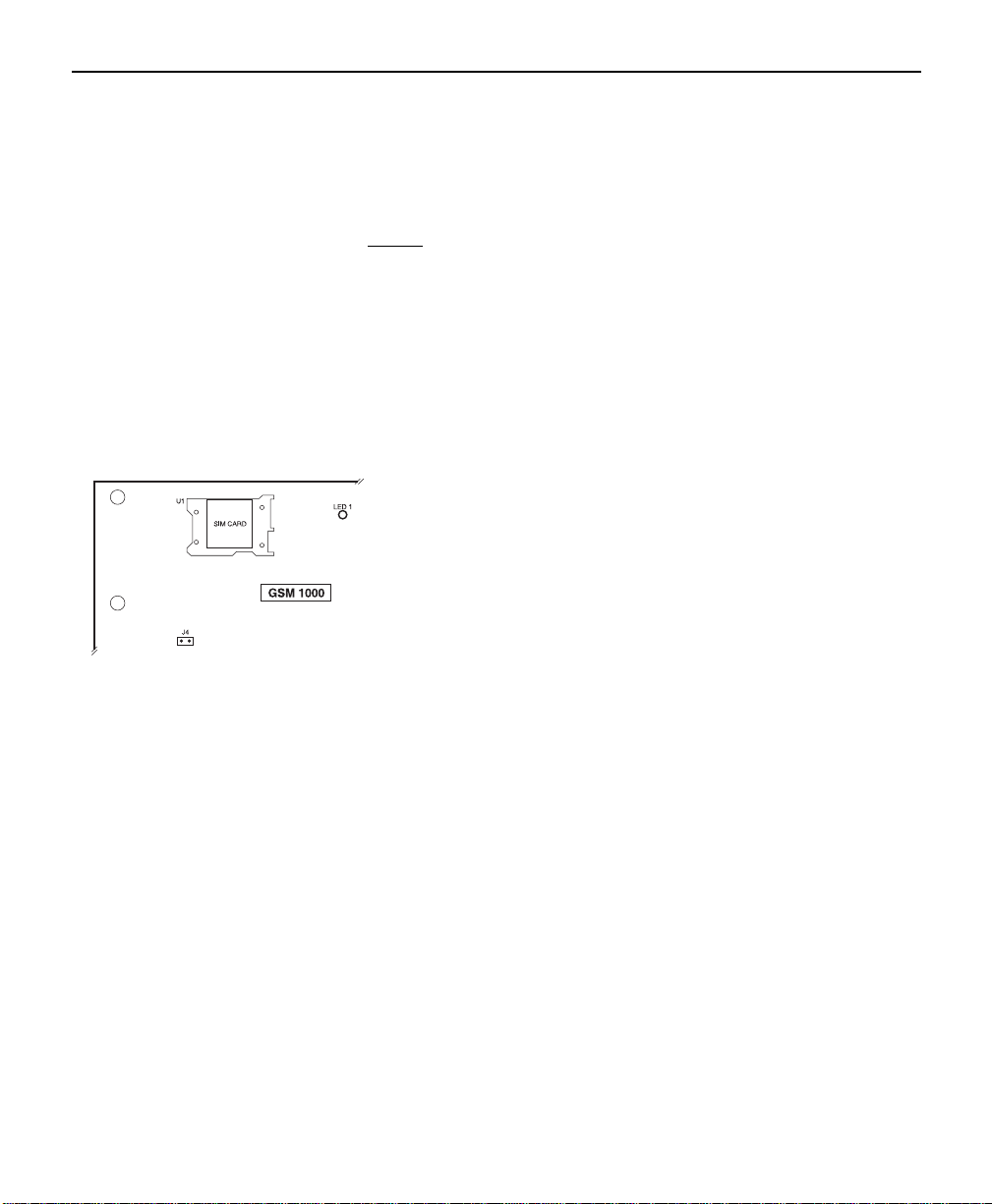
3.1.2 Inserting SIM Card
before
attempting to connect to the network. Registration is done upon
When you have obtained a SIM card from your GSM service provider,
insert it into the SIM Card socket (SIM Lock) on the GSM 1000 module.
Simply slide the cover to the right and pull open. Then insert your card
and close the lid.
3.2 Mounting Module in Cabinet
The metal bracket that accommodates the GSM 1000 is mounted in the upper right hand corner of the
control panel cabinet with the antenna going through the knock out. The GSM 1000 mounting bracket
attaches to the panel cabinet through the use of clips and screws. Please note, however, that the clips (metal
teeth) make it purposely difficult to remove the module once it is installed. Because of the nature of the
installation, it may be difficult to access the connection terminals of the control panel. It is therefore
recommended that wiring connections be made to the control panel before the module is installed.
There may be situations where the cabinet you are using does not accommodate the antenna mount
location properly. In such cases, you may order an optional cabinet, which will fit the GSM 1000 module
properly. You may also remove the antenna mast from the antenna bracket of the GSM 1000 module, and
reattach it through another hole in the cabinet you are using. Please ensure that antenna mast does not
contact the cabinet.
Note: If it is not possible to install the antenna with the antenna mast fastened to the antenna bracket of the
GSM 1000 module (i.e. relocating to another knock out), the antenna tamper switch cannot be used
effectively.
The GSM 1000 should not be located near sources of interference. These sources include EMI
(Electromagnetic Interference) generated by television or heavy electric motors, such as those found in
heating or air conditioning units.
3
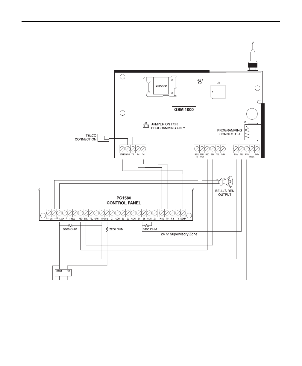
HOOKUP DIAGRAM - PC1580
4
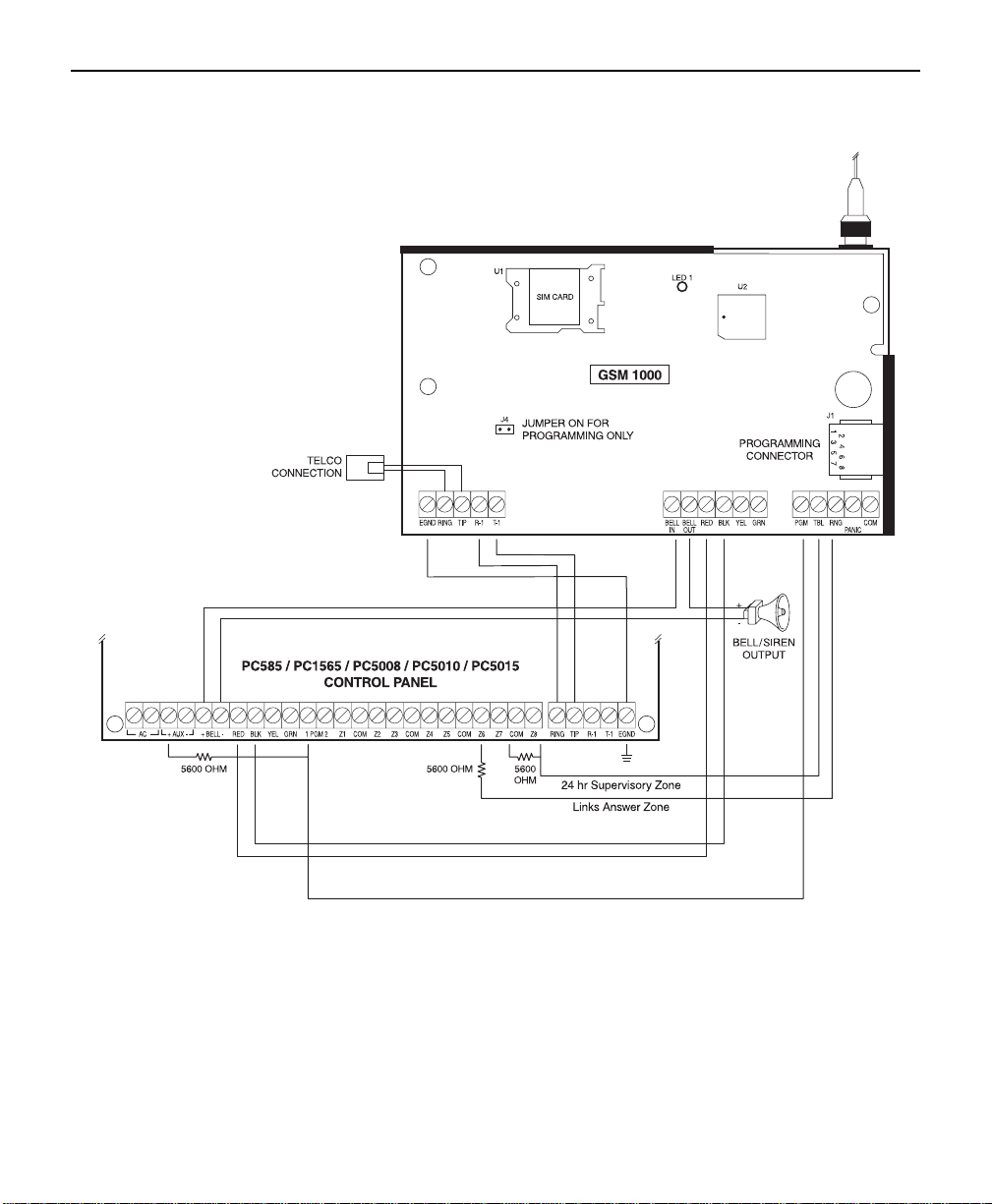
HOOKUP DIAGRAM PC585 / PC1565 / PC5008 / PC5010 / PC5015
5
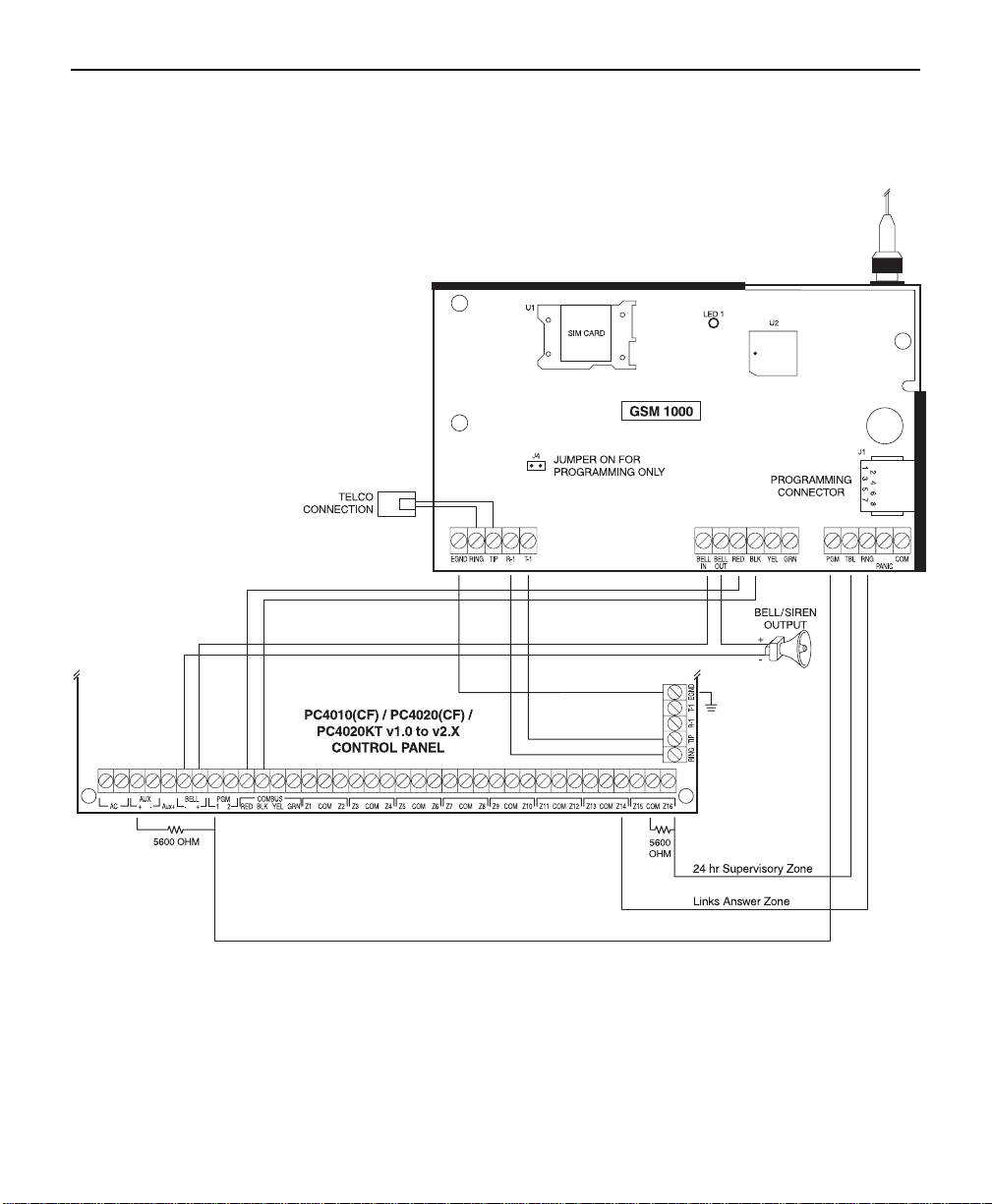
HOOKUP DIAGRAM PC4010(CF) / PC4020(CF) / PC4020KT V1.0 TO V2.X
6
 Loading...