

Page 1

Installation Instructions
alarm shop
Instructions d’Installation
Instrucciones de Instalacion
LCD5511
version 1.O
WARNING: Please refer to the System Installation Manual for information on limitations
regarding product use and function and information on the limitations as to liability of the
manufacturer.
ATTENTION: Ce manuel contient des informations sur les restrictions concernant le
fonctionnement et l’utilisation du produit et des informations sur les restrictions en ce qui
concerne la responsabilité du fabricant. La totalité du manuel doit être lu attentivement.
ADVERTENCIA: Este manual, contiene información sobre restricciones acerca del
uso y funcionamiento del producto e información sobre las limitaciones, tal como, la responsabilidad del fabricante. Todo el manual se debe leer cuidadosamente.
Page 2

alarm shop
Page 3
Introduction
alarm shop
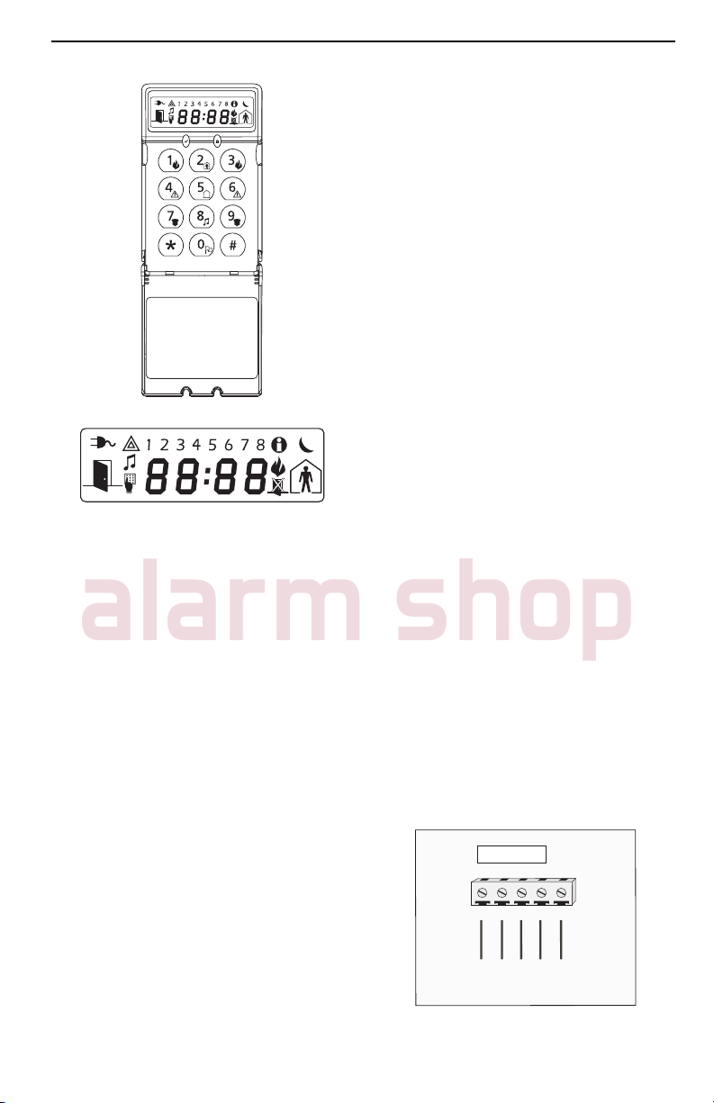
The LCD5511 keypad presents system
status using an LCD display along with
symbols and numbers. The keypad can
be used on security systems with up to
64 zones. The LCD5511 is compatible
with the following DSC security systems:
• PC580/PC585 • PC5008
• PC1555/PC1565 • PC50XX
Specifications
• Voltage rating: 12VDC nominal
• Connects to control panel via 4-wire
Keybus
• One keypad zone input/PGM output
• Current draw: 22mA (standby) / 85mA
(maximum)
• Optional tamper version
• Four programmable function keys
• Ready (green) and Armed (red) status
lights
• Low temperature sensor
Installation
Unpacking
The LCD5511 package includes the following parts:
• One LCD5511 keypad
• Four mounting screws
• one end-of-line resistor
• three keypad inner door labels
• one tamper switch
• surface tape
• one user Instruction Manual
• one Installation Manual
Mounting
You should mount the keypad where it is
accessible to designated points of entry
and exit. Once you have selected a dry
and secure location, perform the following steps to mount the keypad.
Remove the keypad backplate by
loosening the screw (optional) located
at the base of the unit.
Secure the keypad backplate to the
wall in the desired location. Use the
screws provided.
To use the keypad tamper, insert the
tamper switch supplied into the opening
located in the centre of the backplate.
For tamper use, try to ensure the back-
plate is mounted on a smooth, flat surface. If mounting on a rough surface,
fasten the enclosed surface tape to
the wall to even out the surface area
where the tamper will be positioned.
Before attaching the keypad to its
backplate, complete the keypad wiring as described in the next section.
Wiring
1. Before wiring the unit, ensure that all
power (AC transformer and battery) is
disconnected from the control panel.
2. Connect the four Keybus wires from
the control panel (red, black, yellow
and green) to the keypad terminals (R
B Y G). Consult the diagram below:
LCD5511
RBYG
RED BLK YEL GRN
Z/P
To Zone Input/
PGM Output
1
Page 4

3. If programmed as an input, you can
alarm shop
connect a device - such as a door
contact - to the ‘Z/P’ terminal of the
LCD5511. This eliminates the need to
run wires back to the control panel for
the device. To connect the zone, run
one wire from the device to the ‘Z/P’
terminal and the other wire from the
device to the B (black) terminal. For
powered devices, run the red wire to
the R (positive) terminal and the black
wire to the B (negative) terminal. When
using end of line supervision, connect
the zone according to one of the configurations outlined in your system’s
Installation Manual.
4. If the ‘Z/P’ terminal is programmed as
an output, the output follows the PGM
programmed in Section [000][8]. A
small relay, buzzer or other DC operated device may be connected between
the positive supply voltage and the ‘Z/
P’ terminal (maximum load is 50mA).
Applying Power
Once all wiring is complete, apply power
to the control panel:
1. Connect the battery leads to the battery.
2. Connect the AC transformer.
For more information on control panel
power specifications, see the control
panel Installation Manual.
NOTE: Do not connect the power until all wiring is complete.
Enrolling the Keypad
Once all wiring is complete, you will need
to enter a 2-digit number that tells the
system the partition and slot assignment
of the keypad.
If your system has partitions, you will
need to also assign the keypad to a partition (1st digit).
The slot assignment (2nd digit) tells the
panel which keypad slots are occupied.
The panel can then generate a fault when
a keypad supervisory signal is not
present. There are eight available slots
for keypads. LCD5511 keypads are always assigned to slot 1 by default. You
will need to assign each keypad to its
own slot (1 to 8).
Enter the following at each keypad installed on the system:
Enter Installer Programming by pressing [
✱
][8][Installer’s Code]
Press [000] for Keypad Programming
Press [0] for Partition and Slot Assignment
Enter a two digit number to specify the
partition and slot assignment.
NOTE: If your system does not have partitions,
enter [1] for the first digit.
1st digit Enter 0 for Global Keypad
Enter 1 for Partition 1 Keypad
Enter 2 for Partition 2 Keypad
Enter 3 for Partition 3 Keypad
Enter 4 for Partition 4 Keypad
Enter 5 for Partition 5 Keypad
Enter 6 for Partition 6 Keypad
Enter 7 for Partition 7 Keypad
Enter 8 for Partition 8 Keypad
2nd digit Enter 1 to 8 for Slot Assignment
5. Press the [#] key twice to exit programming.
6. After assigning all keypads, perform a
supervisory reset by entering
[
✱
][8][Installer’s Code][902]. The panel will now supervise all assigned keypads and enrolled modules on the
system.
Programming the Keypad
There are several programming options
available for the LCD5511 keypad. These
are described below. Record all your
programming choices in the programming worksheets included in this manual.
Programming the LCD5511 is similar to
programming the rest of the system.
When you are in the LCD5511 programming sections, the keypad will display
which options are turned on along the top
of the display. To turn an option on or off,
press the number corresponding to the
option on the number pad. The numbers
of the options that are currently turned
ON will be displayed.
2
Page 5
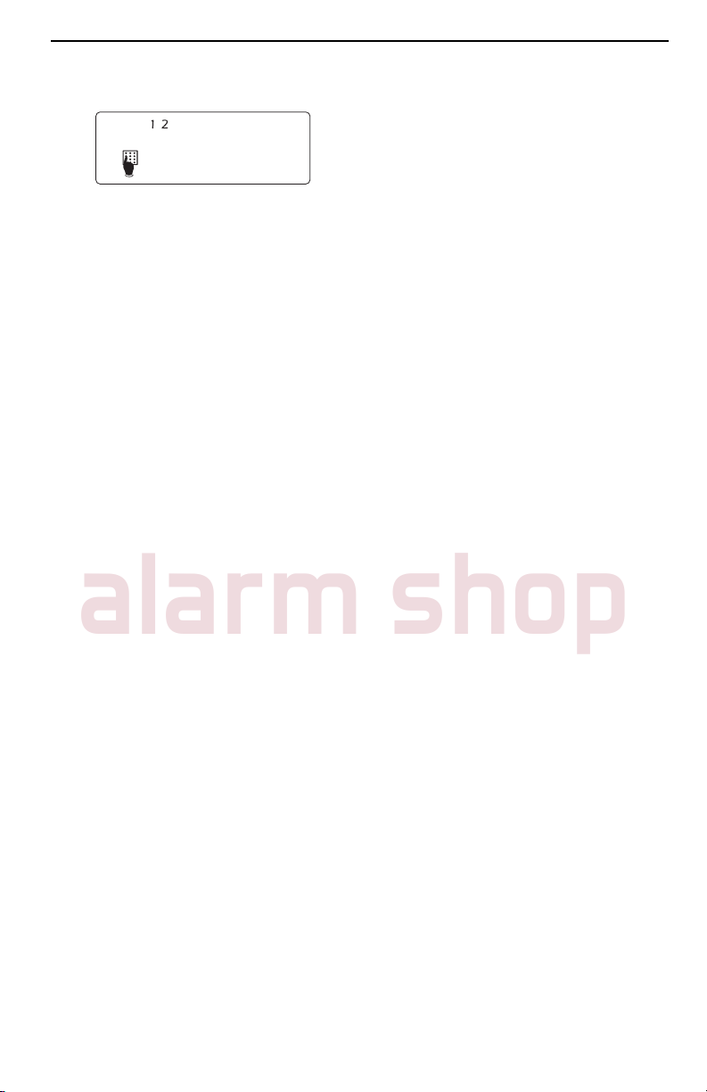
For example, if options 1 and 2 are on,
alarm shop
the display will look like:
For information on programming the rest
of your security system, please refer to
your system’s Installation Manual.
Function Key Options
The function keys are programed in sections [000][1-4]. By default, the 4 function
keys on the keypad are programmed as
Stay Arm (03), Away Arm (04), Chime
(06), Aux (11). You can change the function of each key on every keypad. Please
see your system’s Installation Manual for
instructions on programming the keys,
and a complete list of all the function key
options available for your system.
Clock Options
The LCD5511 will display the current
time after 4 seconds of no key presses.
To set the correct time and date for the
system, please refer to your system’s Instruction Manual. You can change how
the keypad displays the time with the following options. To change the clock options:
1. Enter [
2. Enter [000] to go to keypad program-
3. Enter section [6] to go to clock op-
4. To turn any of the options on or off,
NOTE: If the Time does not display on keypad
option is selected, make sure that the Keypad
displays time when zones are open option is
also selected.
[1] ON =Time displays on keypad
[2] ON = Clock display is in 12-hour
format (e.g. 20:00)
✱
][8][Installer’s code]
ming
tions.
press [1], [2], or [3]:
OFF =Time does not display on
keypad
format (e.g. 08:00).
OFF =Clock display is in 24-hour
[3] ON =Keypad does not display time
when zones are open
OFF =Keypad displays time when
zones are open
5. When you are finished programming
the clock options, press [#] to exit.
Alarms Displayed While Armed Option
You can disable the display of alarms on
the keypad when the system is armed.
The display of alarms is enabled by default. To disable the display of alarms
when the system is armed, turn off section [6], option [5]:
1. Enter [
2. Enter [000] to go to keypad program-
3. To turn the display of alarms on or off,
4. Turn option [5] on or off:
5. When you are finished, press [#] to exit.
Emergency Key Options (Fire, Auxiliary,
Panic)
You can enable or disable the Fire, Auxiliary and Panic keys at each keypad.
These keys are enabled by default.
Please see your system’s Installation Manual for more information on these keys and
their options. To turn any of the emergency keys on or off on the keypad:
1. Enter [
2. Enter [000] to go to keypad program-
3. Enter section [7].
4. To turn the emergency key options on
[1] ON = Fire key enabled
[2] ON = Auxiliary key enabled
[3] ON = Panic key enabled
5. When complete, press [#] to exit.
✱
][8][Installer’s code]
ming
enter section [6].
>@ 21
= Alarms not displayed
while system is armed
2))
= Alarms are always dis-
played while system is armed
✱
][8][Installer’s code]
ming
or off, press [1], [2], or [3]:
OFF = Fire key disabled
OFF = Auxiliary key disabled
OFF = Panic key disabled
3
Page 6

Door Chime Options
alarm shop
You can program the LCD5511 keypad
to sound a tone when any zone is opened
or closed. There are two parts to the
LCD5511 door chime programming:
• Program if the LCD5511 will chime
when zones are opened and/or
closed.
• Program the type of sound the
LCD5511 will make when an individual
zone is opened or closed.
For the door chime feature to work, you
will also need to turn on the Door Chime
attribute for each zone that will trigger the
chime. This programming is done in the
control panel software. Refer to your control panel’s Installation Manual for more
information.
Door Chime on Zone Openings/Closings
You can program each LCD5511 keypad
to sound a door chime when zones are
opened and/or when they are closed. By
default, LCD5511 keypads are programmed to sound door chimes on both
zone openings and closings.
To change the door chime opening/closing settings, at each LCD5511 keypad:
1. Enter [
2. Enter [000] to go to keypad program-
3. Enter section [6].
4. To turn the options on or off, press [6]
[6]ON =Door Chime Enabled for Zone
[7]ON =Door Chime Enabled for Zone
5. When you are finished, press [#] to exit.
Door Chime Sounds
You can program the LCD5511 keypad
to make different door chime sounds for
individual zones, or groups of zones.
Each LCD5511 keypad can make any of
✱
][8][Installer’s Code]
ming
or [7]:
Openings
OFF =Door Chime Disabled for Zone
Openings
Closings
OFF =Door Chime Disabled for Zone
Closings
four door chime sounds for each zone
that triggers the door chime:
• 4 quick beeps (default sound)
• ‘Bing – Bing’ tone
• ‘Ding – Dong’ tone
• ‘Alarm’ tone
NOTE: For a zone to be able to trigger the
door chime sound, the Door Chime zone attribute must also be enabled in the control panel programming. Please see your control panel
Installation Manual.
To change the door chime sounds:
1. Enter [
2. Enter [
3. Enter a 2-digit number for the zone
4. Turn one of the following options on by
NOTE: Make sure that only one of the above
options is turned on. If more than one is on,
the keypad will sound the first option that is
enabled. If none of the options are selected, the
keypad will not make any sound when the zone
is opened or closed.
5. To program the door chime sound for
6. When you are finished programming
✱
][8][Installer’s code].
✱
] to go to door chime sound
programming.
you want to program [01] - [64].
pressing [1], [2], [3], or [4]:
[1] 4 quick beeps (default sound)
[2] ‘Bing – Bing’ tone
[3] ‘Ding – Dong’ tone
[4] ‘Alarm’ tone
another zone, repeat steps 3 and 4.
the door chime sounds, press [#] to
exit.
Zone Input/PGM Output Option
The LCD5511 ‘Z/P’ terminal can be programmed to support one zone input (default) or one PGM output. To change this
option:
1. Enter [
2. Enter [000] to go to keypad program-
3. Enter section [6].
4. Turn the option on or off by pressing
ming.
[8].
✱
][8] [Installer Code].
4
Page 7

If Option 8 is ON, the ‘Z/P’ terminal is an
alarm shop
output.
If Option 8 is OFF, the ‘Z/P’ terminal is an
input.
Programming the PGM Number
In order to assign a PGM output to the “Z/P”
terminal, a PGM number must be entered.
This number has to be one of the PGM outputs that can be programmed in the panel.
1. Enter [
2. Enter [000] to go to Keypad Program-
3. Enter Section [8].
4. Enter the 2-digit PGM number (01-14).
ming.
✱
][8] [Installer Code].
AC Icon (PC5020 only)
The AC icon displays the AC is present at
the main panel. You can program the
LCD5511 to either go out or flash when
the AC is not present.
1. Enter [✱][8] [Installer Code]
2. Enter [000] to go to Keypad Programming.
3. To select the desired operation for the
AC icon, enter section [6].
4. Turn Option [4] On or Off:
ON = AC Icon flash on loss of power
OFF = AC icon not displayed on loss of
power
5. When you are finished, press [#] to exit.
Tro u b le Icon
The Trouble icon is displayed when a
system trouble is active.
Low Temperature Warning
The keypad zone can be alternatively programmed to be a low temperature warning instead of a physical zone input. If
programmed, the zone will go into alarm
at 6oC (+/-2o) and restore at 9oC (+/-2o).
1. Enter [
2. Enter [000] to go to Keypad Program-
3. Enter section [7].
4. Enable or disable the low temperature
ON = Low temperature warning enabled
OFF = Low temperature warning disabled
NOTE: Only 1 of 3 options may be selected for
the input/output terminal (Zone, PGM or Low
Temperature).
✱
][8] [Installer Code].
ming.
warning by pressing [8].
5
Page 8

Programming Worksheets
alarm shop
[000] Keypad Programming
1. Enter [✱][8][Installer’s code]
2. Enter [000] to go to keypad programming
[0] Keypad Enrollment
Valid entries are 01-18; e.g. enter [11] for partition 1, slot 1.
1st digit Enter 0 for Global Keypad
Enter 1 for Partition 1 Keypad
Enter 2 for Partition 2 Keypad
Enter 3 for Partition 3 Keypad
Enter 4 for Partition 4 Keypad
Enter 5 for Partition 5 Keypad
Enter 6 for Partition 6 Keypad
Enter 7 for Partition 7 Keypad
Enter 8 for Partition 8 Keypad
2nd digit Enter 1 to 8 for Slot Assignment
'HIDXOW
11
[1]-[4] Function Key Assignments
Defaults: 03 04 06 11
NOTE: To assign function keys, please refer to your System’s Installation Manual.
[6] LCD5511 Keypad Options
I_________I________|
>@.H\ >@.H\ >@.H\ >@.H\
Stay Away Chime [✱][5]
I________I________I I________I________I I________I________I I________I________I
'HIDXOW 2SWLRQ
ON
ON
OFF
OFF
OFF
ON
ON
OFF
I________I
I________I
I________I
I________I
I________I
I________I
I________I
I________I
1
2
3
4
5
6
7
8
21= Local clock display enabled
2)) = Local clock display disabled
21= Local clock displays AM/PM
2)) = Local clock displays 24 hour time
21= Open zones override clock display
2)) = Open zones do not override clock display
21= AC icon flashes on loss of power
2)) = AC icon not displayed on loss of power
21= Alarms not displayed while armed
2)) = Alarms always displayed while armed
21= Door chime enabled for zone openings
2)) = Door chime disabled for zone openings
21= Door chime enabled for zone closings
2)) = Door chime disabled for zone closings
21= ‘Z/P’ terminal is an output
2)) = ‘Z/P’ terminal is an input
6
Page 9

[7] Emergency Key Options
alarm shop
'HIDXOW 2SWLRQ 21 2))
ON
ON
ON
OFF
OFF
[8] PGM Terminal
'HIDXOW
01
I________I
I________I
I________I
I________I
I________I
I_________I________|
1 [F] key enabled [F] key disabled
2 [A] key enabled [A] key disabled
3 [P] key enabled [P] key disabled
4-7 For Future Use
8
PGM Output Number (01-14)
Low temperature
warning enabled
Low temperature
warning disabled
[✱] Door Chime Sound Programming
1. Enter [✱][8][Installer’s code][✱]
2. Enter 2-digit zone number [01] - [64], then select door chime sound option [1] - [4].
Repeat for each zone that is to sound a chime.
=RQHV
>@>@
2SWLRQV
>@
EHHSV
GHIDXOW
>@
³ELQJELQJ´
>@
³GLQJGRQJ´
>@
$ODUP7RQH
7
Page 10

Limited Warranty
alarm shop
Digital Security Controls Ltd. warrants the original purchaser that for a period of twelve months from the date of
purchase, the product shall be free of defects in materials
and workmanship under normal use. During the warranty
period, Digital Security Controls Ltd. shall, at its option,
repair or replace any defective product upon return of the
product to its factory, at no charge for labour and materials. Any replacement and/or repaired parts are warranted
for the remainder of the original warranty or ninety (90)
days, whichever is longer. The original purchaser must
promptly notify Digital Security Controls Ltd. in writing
that there is defect in material or workmanship, such written notice to be received in all events prior to expiration
of the warranty period. There is absolutely no warranty on
software and all software products are sold as a user
license under the terms of the software license agreement
included with the product. The Customer assumes all
responsibility for the proper selection, installation, operation and maintenance of any products purchased from
DSC. Custom products are only warranted to the extent
that they do not function upon delivery. In such cases,
DSC can replace or credit at its option.
International Warranty
The warranty for international customers is the same as
for any customer within Canada and the United States,
with the exception that Digital Security Controls Ltd.
shall not be responsible for any customs fees, taxes, or
VAT that may be due.
Warranty Procedure
To obtain service under this warranty, please return the
item(s) in question to the point of purchase. All authorized distributors and dealers have a warranty program.
Anyone returning goods to Digital Security Controls Ltd.
must first obtain an authorization number. Digital Security Controls Ltd. will not accept any shipment whatsoever for which prior authorization has not been obtained.
Conditions to Void Warranty
This warranty applies only to defects in parts and workmanship relating to normal use. It does not cover:
• damage incurred in shipping or handling;
• damage caused by disaster such as fire, flood, wind,
earthquake or lightning;
• damage due to causes beyond the control of Digital
Security Controls Ltd. such as excessive voltage,
mechanical shock or water damage;
• damage caused by unauthorized attachment, alterations, modifications or foreign objects;
• damage caused by peripherals (unless such peripherals
were supplied by Digital Security Controls Ltd.);
• defects caused by failure to provide a suitable installation environment for the products;
• damage caused by use of the products for purposes
other than those for which it was designed;
• damage from improper maintenance;
• damage arising out of any other abuse, mishandling or
improper application of the products.
Items Not Covered by Warranty
In addition to the items which void the Warranty, the following items shall not be covered by Warranty: (i) freight cost
to the repair centre; (ii) products which are not identified
with DSC's product label and lot number or serial number;
(iii) products disassembled or repaired in such a manner as
to adversely affect performance or prevent adequate inspection or testing to verify any warranty claim. Access cards or
tags returned for replacement under warranty will be credited or replaced at DSC's option. Products not covered by
this warranty, or otherwise out of warranty due to age, misuse, or damage shall be evaluated, and a repair estimate
shall be provided. No repair work will be performed until a
valid purchase order is received from the Customer and a
Return Merchandise Authorisation number (RMA) is issued
by DSC's Customer Service.
Digital Security Controls Ltd.’s liability for failure to
repair the product under this warranty after a reasonable
number of attempts will be limited to a replacement of the
product, as the exclusive remedy for breach of warranty.
Under no circumstances shall Digital Security Controls
Ltd. be liable for any special, incidental, or consequential
damages based upon breach of warranty, breach of contract, negligence, strict liability, or any other legal theory.
Such damages include, but are not limited to, loss of profits, loss of the product or any associated equipment, cost
of capital, cost of substitute or replacement equipment,
facilities or services, down time, purchaser’s time, the
claims of third parties, including customers, and injury to
property. The laws of some jurisdictions limit or do not
allow the disclaimer of consequential damages. If the
laws of such a jurisdiction apply to any claim by or
against DSC, the limitations and disclaimers contained
here shall be to the greatest extent permitted by law.
Some states do not allow the exclusion or limitation of
incidental or consequential damages, so that the above
may not apply.
Disclaimer of Warranties
This warranty contains the entire warranty and shall be in
lieu of any and all other warranties, whether expressed or
implied (including all implied warranties of merchantability or fitness for a particular purpose) and of all other
obligations or liabilities on the part of Digital Security
Controls Ltd. Digital Security Controls Ltd. neither
assumes responsibility for nor authorizes any other person
purporting to act on its behalf to modify or to change this
warranty, nor to assume for it any other warranty or liability concerning this product.
This disclaimer of warranties and limited warranty are
governed by the laws of the province of Ontario, Canada.
WARNING: Digital Security Controls Ltd. recommends
that the entire system be completely tested on a regular
basis. However, despite frequent testing, and due to, but
not limited to, criminal tampering or electrical disruption, it is possible for this product to fail to perform as
expected.
Out of Warranty Repairs
Digital Security Controls Ltd. will at its option repair or
replace out-of-warranty products which are returned to its
factory according to the following conditions. Anyone
returning goods to Digital Security Controls Ltd. must
first obtain an authorization number. Digital Security
Controls Ltd. will not accept any shipment whatsoever for
which prior authorization has not been obtained.
Products which Digital Security Controls Ltd. determines
to be repairable will be repaired and returned. A set fee
which Digital Security Controls Ltd. has predetermined
and which may be revised from time to time, will be
charged for each unit repaired.
Page 11

WAR NING
alarm shop
Note to Installers
This warning contains vital information. As the only individual in
contact with system users, it is your responsibility to bring each
item in this warning to the attention of the users of this system.
System Failures
This system has been carefully designed to be as effective as
possible. There are circumstances, however, involving fire, burglary, or other types of emergencies where it may not provide
protection. Any alarm system of any type may be compromised
deliberately or may fail to operate as expected for a variety of
reasons. Some but not all of these reasons may be:
Inadequate Installation
A security system must be installed properly in order to provide
adequate protection. Every installation should be evaluated by a
security professional to ensure that all access points and areas
are covered. Locks and latches on windows and doors must be
secure and operate as intended. Windows, doors, walls, ceilings
and other building materials must be of sufficient strength and
construction to provide the level of protection expected. A
reevaluation must be done during and after any construction
activity. An evaluation by the fire and/or police department is
highly recommended if this service is available.
Criminal Knowledge
This system contains security features which were known to be
effective at the time of manufacture. It is possible for persons
with criminal intent to develop techniques which reduce the
effectiveness of these features. It is important that a security
system be reviewed periodically to ensure that its features
remain effective and that it be updated or replaced if it is found
that it does not provide the protection expected.
Access by Intruders
Intruders may enter through an unprotected access point, circumvent a sensing device, evade detection by moving through
an area of insufficient coverage, disconnect a warning device, or
interfere with or prevent the proper operation of the system.
Power Failure
Control units, intrusion detectors, smoke detectors and many
other security devices require an adequate power supply for
proper operation. If a device operates from batteries, it is possible for the batteries to fail. Even if the batteries have not failed,
they must be charged, in good condition and installed correctly.
If a device operates only by AC power, any interruption, however brief, will render that device inoperative while it does not
have power. Power interruptions of any length are often accompanied by voltage fluctuations which may damage electronic
equipment such as a security system. After a power interruption
has occurred, immediately conduct a complete system test to
ensure that the system operates as intended.
Failure of Replaceable Batteries
This system’s wireless transmitters have been designed to provide several years of battery life under normal conditions. The
expected battery life is a function of the device environment,
usage and type. Ambient conditions such as high humidity, high
or low temperatures, or large temperature fluctuations may
reduce the expected battery life. While each transmitting device
has a low battery monitor which identifies when the batteries
need to be replaced, this monitor may fail to operate as
expected. Regular testing and maintenance will keep the system
in good operating condition.
Compromise of Radio Frequency (Wireless) Devices
Signals may not reach the receiver under all circumstances
which could include metal objects placed on or near the radio
path or deliberate jamming or other inadvertent radio signal
interference.
System Users
A user may not be able to operate a panic or emergency switch
possibly due to permanent or temporary physical disability,
inability to reach the device in time, or unfamiliarity with the
correct operation. It is important that all system users be trained
in the correct operation of the alarm system and that they know
how to respond when the system indicates an alarm.
Smoke Detectors
Smoke detectors that are a part of this system may not properly
alert occupants of a fire for a number of reasons, some of which
follow. The smoke detectors may have been improperly
installed or positioned. Smoke may not be able to reach the
Please Read Carefully
smoke detectors, such as when the fire is in a chimney, walls or
roofs, or on the other side of closed doors. Smoke detectors may
not detect smoke from fires on another level of the residence or
building.
Every fire is different in the amount of smoke produced and the
rate of burning. Smoke detectors cannot sense all types of fires
equally well. Smoke detectors may not provide timely warning
of fires caused by carelessness or safety hazards such as smoking in bed, violent explosions, escaping gas, improper storage of
flammable materials, overloaded electrical circuits, children
playing with matches or arson.
Even if the smoke detector operates as intended, there may be
circumstances when there is insufficient warning to allow all
occupants to escape in time to avoid injury or death.
Motion Detectors
Motion detectors can only detect motion within the designated
areas as shown in their respective installation instructions. They
cannot discriminate between intruders and intended occupants.
Motion detectors do not provide volumetric area protection.
They have multiple beams of detection and motion can only be
detected in unobstructed areas covered by these beams. They
cannot detect motion which occurs behind walls, ceilings, floor,
closed doors, glass partitions, glass doors or windows. Any type
of tampering whether intentional or unintentional such as masking, painting, or spraying of any material on the lenses, mirrors,
windows or any other part of the detection system will impair
its proper operation.
Passive infrared motion detectors operate by sensing changes in
temperature. However their effectiveness can be reduced when
the ambient temperature rises near or above body temperature
or if there are intentional or unintentional sources of heat in or
near the detection area. Some of these heat sources could be
heaters, radiators, stoves, barbeques, fireplaces, sunlight, steam
vents, lighting and so on.
Warning Devices
Warning devices such as sirens, bells, horns, or strobes may not
warn people or waken someone sleeping if there is an intervening wall or door. If warning devices are located on a different
level of the residence or premise, then it is less likely that the
occupants will be alerted or awakened. Audible warning
devices may be interfered with by other noise sources such as
stereos, radios, televisions, air conditioners or other appliances,
or passing traffic. Audible warning devices, however loud, may
not be heard by a hearing-impaired person.
elephone Lines
If telephone lines are used to transmit alarms, they may be out
of service or busy for certain periods of time. Also an intruder
may cut the telephone line or defeat its operation by more
sophisticated means which may be difficult to detect.
Insufficient Time
There may be circumstances when the system will operate as
intended, yet the occupants will not be protected from the emergency due to their inability to respond to the warnings in a
timely manner. If the system is monitored, the response may not
occur in time to protect the occupants or their belongings.
Component Failure
Although every effort has been made to make this system as
reliable as possible, the system may fail to function as intended
due to the failure of a component.
Inadequate Testing
Most problems that would prevent an alarm system from operating as intended can be found by regular testing and maintenance. The complete system should be tested weekly and
immediately after a break-in, an attempted break-in, a fire, a
storm, an earthquake, an accident, or any kind of construction
activity inside or outside the premises. The testing should
include all sensing devices, keypads, consoles, alarm indicating
devices and any other operational devices that are part of the
system.
Security and Insurance
Regardless of its capabilities, an alarm system is not a substitute
for property or life insurance. An alarm system also is not a substitute for property owners, renters, or other occupants to act
prudently to prevent or minimize the harmful effects of an
emergency situation.
Page 12

Introduction
alarm shop
Le clavier LCD5511 indique les états du
système à l’aide de symboles et de
numéros qu’il fait apparaître sur son
afficheur à cristaux liquides. Ce clavier
peut être utilisé avec des systèmes de
sécurité protégeant jusqu’à 64 zones.
Le LCD5511 est compatible avec les
systèmes de sécurité DSC suivants :
• PC580/PC585 • PC5008
• PC1555/PC1565 • PC50XX
Spécifications
• Tension nominale : 12Vc.c
• Raccordement au panneau de
contrôle via le Keybus à 4 fils.
• Une entrée de zone et une sortie PGM
• Consommation de courant : 22mA (en
veille) / 85mA (maximum)
• Version avec interrupteur
antisabotage optionnelle
• Quatre touches de fonctions
programmables
• Voyants d’état Prêt (vert) et Armé
(rouge)
• Capteur de basse température
Installation
Déballage
La boîte du LCD5511 contient les
éléments suivants :
• Un clavier LCD5511
• Quatre vis de montage
• Un résistance fin de ligne
• Trois étiquettes intérieures pour la
porte du clavier
• Un commutateur anti-sabotage
• Ruban collant
• Un Manuel d’Installation
• Un Manuel d’Instructions
Montage
Pour le montage du clavier, choisissez
un endroit près du point d’entrée qui est
sec, sécuritaire et accessible. Lorsque
vous avez déterminé l’emplacement de
montage, suivez les étapes suivantes :
1. Retirez la partie arrière du clavier en
dévissant la vis (optionnelle) située à la
base de l’unité.
2. À l’aide des vis fournies avec l’unité,
fixez la partie arrière du clavier à
l’endroit choisi.
3. Si l’installation nécessite un
commutateur anti-sabotage, insérez-le
dans l’ouverture ronde située au centre
de la plaque arrière.
4. Pour les utilisations anti-sabotage,
essayez de vous assurer que la
plaquette arrîère est montée sur une
surface lisse et plate. Si vous l'installez
sur une surface rugeuse, mettez le
ruban collant sur le mur afin de lisser la
surface sur laquelle le dispositif antisabotage sera fixé.
5. Avant de fixer le clavier sur sa plaque
arrière, effectuez tout le câblage décrit
dans la rubrique suivante.
Câblage
1. Avant de commencer à câbler l’unité,
assurez-vous que l’alimentation
(transformateur c.a. et batterie) du
panneau de contrôle est coupée.
2. Raccordez les quatre fils du Keybus
qui proviennent du panneau de
contrôle (rouge, noir, jaune et vert) sur
10
Page 13

les bornes (R, B, Y et G) du clavier.
alarm shop
Référez-vous au schéma ci-dessous.
LCD
5511
RBYG
RBYG
3. Si la borne ‘Z/P’ du LCD5511 est
programmée en tant qu’entrée, vous
pouvez raccorder un dispositif sur
cette borne, comme par exemple un
contact de porte. Ceci est un bon
moyen d’économiser du temps et du
câblage en évitant d’avoir à installer
un câble entre le panneau de contrôle
et le contact de la porte qui se trouve
à proximité du clavier. Pour raccorder
la zone, installez un câble entre le
dispositif et le clavier et raccordez un
des fils provenant du dispositif sur la
borne ‘Z/P’ du clavier et un autre sur la
borne B. Si le dispositif doit être
alimenté, raccordez le fil rouge à la
borne R (positif) et le fil noir à la borne
B (négatif).
Si une résistance de fin de ligne doit
être utilisée, raccordez la zone en
vous conformant à l’une des
configurations décrites dans le
manuel d’installation du système.
4. Si la borne ‘Z/P’ est programmée en
tant que sortie, celle-ci suit la
programmation de la sortie PGM
programmée dans la section [000][8].
Un petit relais, un avertisseur sonore
ou un autre dispositif qui fonctionne
sous tension c.c. peut être raccordé
entre la borne d’alimentation positive
et la borne ‘Z/P’ (consommation
maximale de courant de 50mA).
Mise sous tension
Une fois le câblage complété, mettez le
panneau de contrôle sous tension.
1. Raccordez les câbles de batterie à la
batterie.
Z/P
L'entree de zone
sortie de PGM
R = Rouge
B = Noir
Y = Jaune
G = Vert
2. Branchez le transformateur CA.
Pour de plus amples informations sur les
spécifications d’alimentation du panneau
de contrôle, référez-vous au manuel
d’installation du panneau de contrôle.
NOTE: Ne mettez pas le panneau de contrôle
sous tension avant que tout le câblage ait été
complété.
Assignation du clavier
Une fois le câblage complété, vous
devez entrer un numéro à 2 chiffres qui
sert à indiquer au système la partition et
l’emplacement de mémoire qui sont
assignés au clavier.
Si votre système est divisé en partitions,
vous devez également assigner le clavier
à une partition (1
L’assignation de l’emplacement de
mémoire (2e chiffre) permet d’indiquer
au panneau quels sont les emplacements
de mémoire dédiés aux claviers qui sont
occupés. Le panneau peut ainsi générer
une panne de supervion lorsqu’il ne reçoit
pas de signal de présence du clavier. Il y a
huit emplacements de mémoire pour les
claviers. Les claviers LCD5511 sont
toujours assignés par défaut à
l’emplacement de mémoire 1. Vous devez
assigner chaque clavier à un emplacement
de mémoire (1 à 8).
Entrez ce qui suit pour chacun des
claviers qui est installé dans le sytème.
Accédez au mode de programmation
de l’installateur en entrant [
de l’installateur]
Entrez [000] pour accéder à la
programmation du clavier.
Appuyez sur [0] pour accéder à
l’assignation de la partition et de
l’emplacement de mémoire du clavier.
Entrez le numéro à deux chiffres qui
représente la partition et
l’emplacement de mémoire.
NOTE: Si votre système n’est pas divisé en
partitions, entrez [1] comme premier chiffre.
1er chiffre
Entrez [0] pour un clavier global
Entrez [1] pour assigner le clavier à la
partition 1
er
chiffre).
✱
][8][code
11
Page 14

Entrez [2] pour assigner le clavier à la
alarm shop
partition 2
Entrez [3] pour assigner le clavier à la
partition 3
Entrez [4] pour assigner le clavier à la
partition 4
Entrez [5] pour assigner le clavier à la
partition 5
Entrez [6] pour assigner le clavier à la
partition 6
Entrez [7] pour assigner le clavier à la
partition 7
Entrez [8] pour assigner le clavier à la partition 8
2e chiffre
indiquer l’emplacement du clavier.
Entrez un chiffre de 1 à 8 pour
5. Pour quitter le mode de
programmation, appuyez deux fois
sur [#].
6. Une fois tous les claviers assignés,
exécutez une réinitialisation de la
supervision en entrant [
l’installateur][902]. Le panneau
supervisera dorénavant tous les
claviers et les modules qui ont été
assignés dans le système.
✱
][8][code de
Programmation du clavier
Plusieurs options de programmation sont
disponibles pour le clavier LCD5511.
Ces options sont décrites ci-dessous.
Inscrivez tous vos choix de
programmation sur les feuilles de
programmation qui se trouvent à la fin de
ce manuel.
La programmation du LCD5511 est
similaire à celle du reste du système.
Lorsque vous êtes dans le mode de
programmation du LCD5511,
du clavier vous indiquent quelles sont les
options qui sont activées. Pour activer ou
désactiver une option, appuyez sur la
touche numérique qui correspond au
numéro de l’option. Les numéros
d’options qui apparaissent dans le haut
de l’afficheur correspondent aux options
qui sont activées.
l’afficheur
Par exemple, si les options 1 et 2 sont
activées, l’afficheur aura l’air de ceci :
Pour de plus amples informations sur la
façon de programmer le reste du
système, veuillez vous référer au manuel
d’installation du système.
Options pour les touches de fonction
La programmation des touches de
fonction s’effectue dans les sections
[000][1]-[4]. Par défaut, les quatre
touches de fonction du clavier sont
programmées comme suit: armement
en mode à domicile (03), armement en
mode Absent (04), Carillon (06),
fonction Auxiliaire (11). Vous pouvez
modifier la fonction de chacune des
touches de chacun des claviers. Pour
de plus amples informations sur la
programmation des touches de fonction
et pour obtenir une liste complète de
toutes les options pour les touches de
fonctions qui sont disponibles pour
votre système, veuillez vous référer au
manuel d’installation.
Options pour l’horloge
Lorsque aucune touche n’a été enfoncée
depuis plus de 4 secondes, le LCD5511
affiche l’heure. Pour régler l’heure et la
date du système, veuillez vous référer au
manuel d’instructions du système. Vous
pouvez modifier la manière dont le
clavier affiche
suivantes. Pour modifier les options de
l’horloge:
1. Entrez [
2. Entrez [000] pour accéder au mode
de programmation du clavier.
3. Entrez [6] pour accéder à la section
de programmation des options de
l’horloge.
4. Pour activer ou désactiver les options,
appuyez sur [1], [2] ou [3].
NOTE: Si l’heure ne s’affiche pas sur le clavier
et que l’option “heure affichée sur le clavier”
est sélectionnée, assurez-vous que l’option “Le
l’heure
à l’aide des options
✱
][8][code de l’installateur]
12
Page 15

clavier affiche l’heure lorsque des zones sont
alarm shop
ouvertes” est également sélectionnée.
[1] $&7,9e( = L’heure est affichée sur le
clavier
'e6$&7,9e(
affichée sur le clavier
[2]
$&7,9e(
format 12 heures (par ex.: 08:00).
'e6$&7,9e(
format 24 heures (par ex.: 20:00)
$&7,9e(
[3]
l’heure lorsque des zones sont ouvertes
'e6$&7,9e(
lorsque des zones sont ouvertes
5. Une fois la programmation des
options de l’horloge complétée,
appuyez sur [#] pour quitter.
Option d’affichage des alarmes lorsque le
système est armé
Vous pouvez empêcher l’affichage des
alarmes sur le clavier lorsque le système
est armé. Par défaut, les alarmes sont
affichées lorsque le système est armé.
Pour empêcher l’affichage des alarmes
lorsque le système est armé, activez
l’option [5] de la section [6].
1. Entrez [
2. Entrez [000] pour accéder à la
programmation du clavier.
3.
Pour permettre ou empêcher l’affichage
des alarmes, accédez à la section [6].
4. Activez ou désactivez l’option [5].
>@ $&7,9e(
5.
lorsque vous avez terminé, appuyez sur
[#] pour quitter.
Options pour les touches d’urgence
(incendie, auxiliaire et panique)
Vous pouvez activer ou désactiver les
touches d’urgence d’incendie, d’urgence
auxiliaire et de panique de chaque
clavier. Par défaut, ces touches sont
activées. Pour de plus amples
informations sur ces touches et sur leurs
options, veuillez vous référer au manuel
= L’heure n’est pas
= Heure affichée dans le
= Heure affichée dans le
= Le clavier n’affiche pas
= Le clavier affiche l’heure
✱
][8][code de l’installateur]
sont pas affichées lorsque le
système est armé.
'e6$&7,9e(
sont toujours affichées
lorsque le système est armé.
= Les alarmes ne
= Les alarmes
d’installation du système. Pour activer ou
désactiver l’une ou l’autre des touches
d’urgence du clavier :
1. Entrez [
2. Entrez [000] pour accéder à la
3. Accédez à la section [7].
4. Pour activer ou désactiver les touches
[1]
activée
'e6$&7,9e(
désactivée
[2]
activée
'e6$&7,9e(
désactivée
[3]
activée
'e6$&7,9e(
désactivée
5.
Options pour le carillon de porte
Vous pouvez programmer le LCD5511
de façon à ce qu’il émette une tonalité
chaque fois qu’une zone est ouverte ou
fermée, et ce, pour chacune des zones.
La programmation du carillon de porte
du LCD5511 se fait en deux parties:
• Vous devez sélectionner si le carillon
•
Vous devez sélectionnez pour chacune
des zones la tonalité que le LCD5511
fera entendre lorsque la zone
déclenchera le carillon de porte.
Afin qu’une zone puisse déclencher le
carillon de porte, vous devez également
sélectionner l’attribut “Carillon” de cette
zone. La programmation des attributs
des zones se fait dans le logiciel du
panneau de contrôle. Pour de plus
amples informations, veuillez vous
référer au manuel d’installation du
panneau de contrôle.
✱
][8][code de l’installateur]
programmation du clavier
d’urgence, appuyez sur [1], [2] ou [3].
$&7,9e(
$&7,9e(
$&7,9e(
Lorsque vous avez terminé, appuyez sur
[#] pour quitter.
du LCD5511 doit être déclenché lors
des ouvertures ou des fermetures des
zones ou dans les deux cas.
= Touche incendie
= Touche incendie
= Touche auxiliaire
= Touche auxiliaire
= Touche de panique
= Touche de panique
13
Page 16

Carillon de porte lors de l’ouverture/la
alarm shop
fermeture des zones
Vous pouvez programmer chaque clavier
LCD5511 pour qu’il émette une tonalité
carillon lors de l’ouverture ou de la
fermeture des zones ou dans les deux cas.
Par défaut, les claviers LCD5511 sont
programmés pour émettre une tonalité
carillon lors de l’ouverture et de la
fermeture des zones.
Pour modifier le réglage du carillon de
port de chaque clavier LCD5511:
1. Entrez [
2. Entrez [000] pour accéder à la
programmation du clavier.
3. Accédez à la section [6].
4. Pour activer ou désactiver les options,
appuyez sur [6] ou [7].
[6]
llors de l’ouverture des zones
désactivé lors de l’ouverture des
zones
[7]
de la fermeture des zones
désactivé lors de la fermeture des
zones
5.
[#] pour quitter.
Tonalités pour le carillon
Vous pouvez sélectionner, parmi quatre
tonalités différentes, la tonalité qui sera
émise par le clavier LCD5511 pour
chacune des zones ou chacun des
groupes de zones qui déclencheront le
carillon. Ces tonalités sont les suivantes :
•4 bips rapides (tonalité par défaut)
•”Bing – Bing”
•”Ding – Dong”
•Tonalité d’alarme
NOTE: Pour qu’une zone puisse être en
mesure de déclencher le carillon de porte,
l’attribut “Carillon” de cette zone doit être
sélectionné dans la programmation du
panneau de contrôle . Veuillez vous référer au
manuel d’installation du panneau de contrôle.
✱
][8][code de l’installateur]
$&7,9e(
'e6$&7,9e(
$&7,9e(
'e6$&7,9e(
lorsque vous avez terminé, appuyez sur
= Carillon de porte activé
= Carillon de porte
Carillon de porte activé lors
=
= Carillon de porte
Pour modifier la tonalité du carillon de
porte d’une zone :
1. Entrez [✱][8][code de l’installateur].
2. Entrez [
programmation de la tonalité du
carillon de porte.
3. Entrez les 2 chiffres du numéro de la
zone [01] à [64] pour laquelle vous
désirez programmer la tonalité.
4. Activez une des options suivantes en
appuyant sur la touche [1], [2], [3] ou
[4] qui correspond à la tonalité
choisie.
[1] 4 bips rapides (par défaut)
[2] “Bing – Bing”
[3] “Ding – Dong”
[4] Tonalité d’alarme
NOTE: Assurez-vous qu’une seule de ces
options est activée. Si plus d’une option est
activée, le clavier émettra la tonalité qui
correspond à la première option qui est activée.
Si aucune de ces options n’est activée, le
clavier n’émettra aucune tonalité lors des
ouvertures et des fermetures de la zone.
5. Pour programmer la tonalité du
carillon de porte d’une autre zone,
répétez les étapes 3 et 4.
6. Lorsque vous avez terminé la
programmation des tonalités de
carillon de porte, appuyez sur [#] pour
quitter.
✱
] pour accéder à la
Option pour la borne ‘Z/P’
(Entrée de zone/ sortie PGM)
La borne ‘Z/P’ du clavier LCD5511 peut
être programmée en tant qu’entrée de
zone (par défaut) ou de sortie PGM. Pour
modifier cette option :
1. Entrez [
2. Entrez [000] pour accéder à la
3. Accédez à la section [6].
4. Activez ou désactivez l’option en
Si l’option 8 est ACTIVÉE, la borne ‘Z/P’
Si l’option 8 est DÉSACTIVÉE, la borne
✱
][8] [code de l’installateur].
programmation du clavier.
appuyant sur [8].
du clavier est une sortie.
‘Z/P’ est une entrée.
14
Page 17

Programmation du numéro de la PGM
alarm shop
Afin que la borne ‘Z/P’ puisse être utilisée
en tant que sortie PGM, un numéro de
sortie PGM doit être entré. Ce numéro
doit correspondre à un numéro de PGM
qui peut être programmé dans le
panneau.
1. Entrez [
2. Entrez [000] pour accéder à la
3. Accédez à la section [8].
4. Entrez les 2 chiffres du numéro de la
✱
][8] [code de l’installateur].
programmation du clavier.
sortie PGM (01-14).
Icône CA (seulement PC5020)
L’icône CA indique que le panneau de
contrôle est alimenté par l’alimentation
c.a. Vous pouvez programmer le
LCD5511 de façon à ce que, durant une
panne d’alimentation, l’icône CA
disparaisse de l’afficheur ou qu’elle
clignote.
1. Entrez [
2. Enrez [000] pour accéder à la
3. Pour sélectionner le mode d’opération
4. Activez ou désactivez l’option [4]
5. Lorsque vous avez terminé, appuyez
✱
][8] [code de l’installateur]
programmation du clavier.
désiré pour l’icône CA, accédez à la
section [6].
ACTIVÉE = l’icône CA clignote durant
une panne d’alimentation
DÉSACTIVÉE = l’icône CA disparaît de
l’afficheur durant une panne
d’alimentation
sur [#] pour quitter.
Icône Trouble
L’icône Trouble apparaît sur l’afficheur
lorsqu’une condition de trouble est
présente dans le système.
Capteur de basse température
La zone du clavier peut, au lieu d’être
programmée comme entrée de zone,
être programmée en tant que capteur de
basse température. Si cette zone est
programmée en tant que capteur de
basse température, elle passe en état
d’alarme lorsque la température atteint 6
C (± 2o) et se rétablit à 9o C (± 2o).
1. Entrez [
2. Entrez [000] pour accéder à la
3. Accédez à la section [7].
4. Activer ou désactiver l'avertisseur de
ACTIVÉE = Avertisseur de basse
température activé
DÉSACTIVÉE = Avertisseur de basse
température désactivé
NOTE: Une seule des 3 options peut être choisie pour la borne entrée/sortie (Zone, PGM ou
basse température)
✱
][8] [code de l’installateur].
programmation du clavier.
basse température en appuyant sur [8]
o
15
Page 18

Feuilles de programmation
alarm shop
[000] Programmation du clavier
1. Entrez [✱][8][code de l’installateur]
2. Entrez [000] pour accéder à la
programamtion du clavier.
[0] Assignation du clavier
Les entrées valides sont de 01 à 18. Par
exemple, entrez [11] pour la partition
1, emplacement de mémoire 1. Par
défaut = 11
er
1
chiffre Entrez 0 pour un clavier Global
Entrez 1 pour assigner le
clavier à la partition 1
Entrez 2 pour assigner le
clavier à la partition 2
Entrez 3 pour assigner le
clavier à la partition 3
[1] à [4] Assignation des touches de fonction
>@7RXFKH >@7RXFKH >@7RXFKH >@7RXFKH
Par défaut : 03 04 06 11
À domicile Absent Carillon
I________I________I I________I________I I________I________I I________I________I
NOTE: Pour de plus amples informations sur l’assignation des touches de fonction, référez-vous
au manuel d’installation du panneau de contrôle.
[6] Options pour le clavier LCD5511
e
2
correspond à l’emplacement du clavier
Entrez 4 pour assigner le
clavier à la partition 4
Entrez 5 pour assigner le
clavier à la partition 5
Entrez 6 pour assigner le
clavier à la partition 6
Entrez 7 pour assigner le
clavier à la partition 7
Entrez 8 pour assigner le
clavier à la partition 8
chiffre Entrez le numéro de 1 à 8 qui
3DUGpIDXW
11
I_________I________|
[✱][5]
3DUGpIDXW 2SWLRQ
ACTIVÉE
ACTIVÉE
DÉSACTIVÉE
DÉSACTIVÉE
DÉSACTIVÉE
I________I
I________I
I________I
I________I
I________I
1
2
3
4
5
$&7,9e(= Affichage de l’heure activé
'e6$&7,9e( = Affichage de l’heure désactivé
$&7,9e(= Heure affiché en mode AM/PM
'e6$&7,9e( = Heure affichée en mode 24 h
$&7,9e(= Les zones ouvertes remplacent
l’affichage de l’heure
'e6$&7,9e( = Les zones ouvertes ne remplacent
pas l’affichage de l’heure
$&7,9e(= L’icône CA clignote durant une panne
d’alimentation
'e6$&7,9e( = L’icône CA disparaît de l’afficheur
durant une panne d’alimention
$&7,9e(= Les alarmes ne sont pas affichées
lorsque le système est armé
'e6$&7,9e( = Les alarmes sont toujours
affichées lorsque le système est armé
16
Page 19

$&7,9e(= Carillon de porte activé lors des
alarm shop
ACTIVÉE
ACTIVÉE
DÉSACTIVÉE
I________I
I________I
I________I
6
7
8
ouvertures des zones
'e6$&7,9e( = Carillon de porte désactivé lors
des ouvertures des zones
$&7,9e(= Carillon de porte activé lors des
fermertures des zones
'e6$&7,9e( = Carillon de porte désactivé lors
des fermertures des zones
$&7,9e(= La borne ‘Z/P’ est une sortie
'e6$&7,9e( = La borne ‘Z/P’ est une entrée
[7] Options pour les touches d’urgence
3DUGpIDXW 2SWLRQ $&7,9e( 'e6$&7,9e(
ACTIVÉE
ACTIVÉE
ACTIVÉE
DÉSACTIVÉE
DÉSACTIVÉE
I________I
I________I
I________I
I________I
I________I
1 Touche [F] activée Touche [F] désactivée
2 Touche [A] activée Touche [A] désactivée
3 Touche [P] activée Touche [P] désactivée
4 à 7 Pour usage futur
8
Capteur de basse
température activé
Capteur de basse
température désactivé
[8] Borne PGM
3DUGpIDXW
01
I_________I________|
Numéro de sortie PGM (01-14)
[✱] Programmation de la tonalité pour le carillon de porte
1. Entrez [✱][8][code de l’installateur][✱]
2. Entrez les 2 chiffres du numéro de la zone [01] à [64] que vous désirez programmer
et sélectionnez ensuite une des options de tonalité [1] à [4]. Répétez cette procédure
pour chacune des zones qui doit déclencher le carillon de porte.
=RQHV
>@>@
2SWLRQV
>@
ELSV
SDUGpIDXW
>@
³ELQJELQJ´
>@
³GLQJGRQJ´
>@
7RQDOLWpG¶DODUPH
17
Page 20

*$5$17,(/,0,7e(
alarm shop
La société Digital Security Controls Ltée. garantit le produit contre
toutes défectuosités matérielles et d’assemblage dans des conditions
normales d’utilisation, à l’acheteur original, pendant une période de
douze mois à partir de la date d’achat. Dans l’application de cette
garantie, la société Digital Security Controls Ltée. S’engage, à son
choix, à réparer ou à remplacer tout matériel défectueux dès son retour à un dépôt de réparation, sans frais de main d’oeuvre et matériels. Tout remplacement et/ou réparation sont garantis pendant le
reste de la durée de la garantie originale ou quatre vingt dix (90)
jours, ou l’une ou l’autre est la plus longue. Le propriétaire original
doit avertir la société Digital Security Controls Ltée. par courrier
que le matériel ou l’assemblage sont défectueux ; dans tous les cas,
cette notification doit être reçue avant l’expiration de la période de
garantie. Il n'y a absolument aucune garantie sur les logiciels et tous
les logiciels sont vendus comme utilisateur de licence dans le cadre
du contrat licence d'utilisation du produit. Le client assume toute la
responsabilité de la sélection, de l'installation et de l'entretien de tout
produit acheté auprès de DSC. Les produits personnalisés ne sont
garantis que dans la mesure où ils ne fonctionnent pas à la livraison.
Dans ce cas, DSC peut, à son choix, remplacer le produit ou créditer
le client.
*DUDQWLH,QWHUQDWLRQDOH
La garantie pour les clients internationaux est la même que pour
tous les clients au Canada et aux Etats-Unis, sauf que la société
Digital Security Controls Ltée. ne sera pas responsable des frais de
douanes, taxes, ou TVA qui pourraient être dus.
3URFpGXUHSRXUOD*DUDQWLH
Pour obtenir un service sous garantie, veuillez retourner les produit(s) en question au point d’achat. Tous les distributeurs autorisés et vendeurs ont un programme de garantie. Quiconque
retourne des marchandises à la société Digital Security Controls
Ltée. doit tout d’abord obtenir un numéro d’autorisation. La société Digital Security Controls Ltée. n’acceptera aucun envoi pour
lequel une autorisation préalable n’aura pas été obtenue.
&RQGLWLRQVG¶DQQXODWLRQGHOD*DUDQWLH
Cette garantie ne s’applique qu’aux vices de matériels et d’assemblage liés à une utilisation normale. Elle ne couvre pas:
• dommage encouru lors de l’expédition ou la manutention ;
• dommage causé par un désastre tel qu’un incendie, inondation,
vent, tremblement de terre ou foudre ;
• dommage dû à des causes hors du contrôle de la société Digital
Security Controls Ltée. tel que voltage excessif, choc mécanique
ou dommage des eaux ;
• dommage causé par attachement non autorisé, changements,
modifications ou objets étrangers ;
• dommage causé par périphériques (à moins que les périphériques
ne soient fournis par la société Digital Security Controls Ltée.) ;
• défauts causés par l’impossibilité de fournir un environnement
d’installation adapté aux produits ;
• d ommage causé par l’utilisation des produits pour des usages autres que ceux pour lesquels ils ont été conçus ;
• dommage pour mauvais entretien ;
• dommage provenant de tout autre mauvais traitement, mauvaise
manutention ou mauvaise utilisation des produits.
&HTXLQHVWSDVFRXYHUWVSDUODJDUDQWLH
En plus des éléments qui annulent la garantie, la garantie ne couvrira pas : i) les frais de transport au centre de réparation ; ii) les
produits qui ne sont pas identifiés avec l'étiquette de produit de
DSC et un numéro de lot ou un numéro de série ; iii) les produits
démontés ou réparés de manière qui affecte la performance ou qui
empêche une inspection ou un essai afin de vérifier toute réclamation au titre de la garantie. Les cartes ou les insignes d'accès renvoyés pour être remplacés au titre de la garantie seront remplacés
ou crédités au choix de DSC. Les produits qui ne sont pas couverts
par cette garantie ou qui ne sont plus garantis parce qu'ils sont trop
vieux, qu'ils ont été mal utilisés ou endommagés, seront examinés
et une estimation de réparation sera fournie. Aucune réparation ne
sera effectuée avant la réception d'un bon de commande valable
envoyé par le client et d'un numéro d'autorisation de renvoi de
marchandise (RMA) envoyé par le service à la clientèle de DSC.
S’il y a un problème de réparation du produit après un nombre raisonnable de tentatives au titre de la présente garantie, les obligations contractuelles de la société Digital Security Controls Ltée.
seront limitées au remplacement du produit, comme seule réparation de l’inobservation de la garantie. En aucun cas la Société Dig-
ital Security Controls Ltée. ne sera responsable des dommages
particuliers, accidentels ou indirects basés sur l’inobservation de
la garantie, une rupture de contrat, une négligence, une responsabilité stricte ou sur toute autre théorie juridique. De tels dommages
incluent, mais ne sont limités à, une perte de profit, une perte de
produit ou tout autre équipement associé, au coût de capital, au
coût de remplacement de l’équipement, à l’aménagement ou services, à l’indisponibilité, au temps de rachat, aux réclamations des
tiers, notamment les clients, aux dommages et intérêts à la propriété, etc . Dans certaines juridictions, la loi limite ou ne permet
pas une exonération de garantie en cas d'endommagement indirect. Si les lois d'une telle juridiction s'appliquent à une réclamation par ou contre DSC, les limites et les exonérations contenues
dans la présente garantie respecteront la loi. Certains États ne permettent pas l'exonération ou la limite de dommages accidentels ou
indirects, la déclaration ci-dessus pourrait donc ne pas s'appliquer
à votre cas.
6WLSXODWLRQG¶H[RQpUDWLRQGHJDUDQWLHV
Cette garantie contient l’entière garantie et remplace toutes les autres garanties, qu’elles soient explicites ou implicites (notamment
toutes les garanties implicites de marchandise ou aptitude pour un
usage particulier) et de toutes autres obligations ou responsabilités
de Digital Security Controls Ltée. Digital Security Controls Ltée.
n’assume et n’autorise aucune autre personne prétendant agir en
son nom de modifier ou changer cette garantie, n’assume pour cela
aucune autre garantie ou responsabilité concernant ce produit.
Cette stipulation d’exonération de garanties et garantie restreinte
sont gouvernées par les lois de la province de l’Ontario, Canada.
$77(17,21
que la totalité du système soit testé régulièrement. Toutefois,
même si vous faites des essais périodiques, il peut arriver que le
fonctionnement du produit ne soit pas conforme aux spécifications
en raison notamment, mais pas exclusivement, d’interventions
criminelles ou de panne de courant.
Digital Security Controls Ltée. recommande
9HUURXLOODJHGHO¶,QVWDOODWHXU
Tous produits renvoyés à DSC qui ont une option verrouillage de
l’Installateur activée et ne montrent pas d’autres problèmes seront
sujets à des frais d’entretien.
Réparations en dehors de la Garantie
Digital Security Controls Ltée. réparera à son choix ou remplacera
en dehors de la garantie les produits renvoyés à son usine dans les
conditions suivantes. Quiconque retourne des produits à Digital
Security Controls Ltée. doit d’abord obtenir un numéro d’autorisation. Digital Security Controls Ltée. n’acceptera aucun envoi
quel qu’il soit, pour lequel une autorisation préalable n’aura pas
été obtenue.
Les produits que Digital Security Controls Ltée. juge être réparables seront réparés et renvoyés. Les frais prédéterminés par Digital
Security Controls Ltée., et sujets à un rajustement périodique, seront facturés pour chaque unité réparée.
Les produits que Digital Security Controls Ltée. juge ne pas être
réparables seront remplacés par le produit équivalent le plus
proche disponible à ce moment. Le prix du marché en cours du
produit de remplacement sera facturé pour chaque unité de remplacement.
ATTENTION à lire attentivement
Note pour les installateurs
Cette mise en garde contient des informations vitales. En tant que
seul individu en contact avec les utilisateurs du système, c’est à
vous qu’incombe la responsabilité d’attirer l’attention des utilisateurs du système sur chaque élément de cette mise en garde.
Pannes de Système
Ce système à été soigneusement conçu pour être aussi efficace que
possible. Toutefois, dans des circonstances, où il y a feu, cambriolage ou autre genre d’urgences, il ne peut pas fournir de protection. Tout système d’alarme quel qu’il soit peut être saboté ou peut
ne pas fonctionner comme prévu pour plusieurs raisons. Certaines
de ces raisons sont notamment :
Mauvaise Installation
Un système de sécurité doit être correctement installé pour fournir
une protection adéquate. Chaque installation doit être évaluée par
un professionnel de la sécurité pour s’assurer que tous points d’accès et aires sont couvertes. Serrures et loquets sur les fenêtres et
portes doivent être bien fermés et fonctionner comme prévu. Les
matériels de construction des fenêtres, portes, murs, plafonds et
autres doivent assez solides pour assurer le niveau de protection
Page 21

attendue. Une réévaluation doit être effectuée pendant et après
alarm shop
toute construction. Une évaluation par les sapeurs-pompiers et/
ou les services de police est grandement recommandée si ce service est offert.
Connaissances Criminelles
Ce système contient des fonctions de sécurité reconnues efficaces au moment de la fabrication. Il est possible que des personnes
ayant des intentions criminelles élaborent des techniques qui réduisent l’efficacité de ces fonctions. Il est important qu’un système sécurité soit réexaminé périodiquement pour assurer que
ces fonctions restent fonctionnelles et pour les actualiser ou les
remplacer si elles n’assurent plus la protection attendue.
Accès par des Intrus
Des intrus peuvent entrer par un point d’accès non protégé en
contournant une unité de détection, échapper à une détection en
se déplaçant dans une zone à couverture insuffisante, déconnecter une unité d’alerte, ou interférer avec le système ou empêcher
son fonctionnement normal.
Panne de Courant
Les unités de Contrôle, les détecteurs d’intrusion, les détecteurs
de fumée et bien d’autres dispositifs de sécurité nécessitent une
alimentation électrique pour fonctionner normalement. Si un dispositif fonctionne à partir de piles, il est possible que les piles
faiblissent. Même si les piles ne sont pas faibles, elles doivent
être changées, en bonne condition et installées correctement. Si
un dispositif ne fonctionne que par courant électrique, toute interruption, même brève, rendra ce dispositif inopérant pendant la
durée de la coupure de courant. Les coupures de courant, quelle
qu’en soit la durée, sont souvent accompagnées par des fluctuations de voltage qui peuvent endommager l’équipement électronique tel qu’un système de sécurité. Après qu’une coupure de
courant s’est produite, effectuez immédiatement un test complet
du système pour vous assurer que le système fonctionne correctement
Panne de Piles Remplaçables
Les transmetteurs sans fils de ce système ont été conçus pour
fournir plusieurs années d’autonomie de piles sous des conditions normales. La durée de vie de la pile dépend de l’environnement du dispositif, de utilisation et du type de pile. Les conditions
ambiantes telles que l’humidité élevée, des températures très
élevée ou très bases, ou de grosses différences de température
peuvent réduire la durée de vie de la pile. Bien que chaque dispositif de transmission possède un dispositif de surveillance de
pile faible et qu’il indique quand les piles ont besoin d’être remplacée, il peut ne pas fonctionner comme prévu. Des tests et un
entretien régulier garderont le système dans de bonne condition
de fonctionnement.
Limites de fonctionnement des Dispositifs de Fréquence
Radio (Sans Fils)
Les signaux peuvent ne pas atteindre le récepteur dans toutes les
circonstances qui pourraient inclure objets métalliques placés sur
ou à côté du chemin radio ou blocage délibéré ou autre interférence du signal radio commis par inadvertance.
Les Utilisateurs du Système
Un utilisateur peut ne pas être en mesure de faire fonctionner un
interrupteur de panique ou d’urgence à cause d’une invalidité
permanente ou temporaire, d’une incapacité d’atteindre le dispositif à temps, ou d’un manque de connaissance de la bonne
fonction. Il est important que tous les utilisateurs du système soient formés sur le bon fonctionnement du système d’alarme pour
qu’ils sachent comment réagir quand le système indique une
alarme.
Détecteurs de Fumée
Les détecteurs de fumée qui font partie du système peuvent ne
pas bien alerter les occupants d’un endroit en feu pour un certains
nombre de raisons, en voici quelques une. Le détecteurs de fumée
peuvent avoir été mal installés ou positionnés. La fumée peut ne
pas pouvoir atteindre le détecteurs de fumée, par exemple : un
incendie dans une cheminée, murs ou toits, ou de l’autre côté de
portes fermées. Les détecteurs de fumée peuvent ne pas détecter
la fumée provenant d’incendies à un autre niveau de la résidence
ou du bâtiment.
Tous les incendies différent par la quantité de fumée produite et
le taux de combustion. Les détecteurs de fumée ne peuvent pas
détecter de la même manière tous les types d’incendies. Les détecteurs de fumée ne fournissent pas d’avertissement opportun
d’un incendie causé par une imprudence ou un manque de sécurité tels que fumer dans le lit, explosions violentes, fuites de gaz,
mauvais rangement de produits inflammables, circuits électriques surchargés, enfants jouant avec des allumettes.
Même si le détecteur de fumée fonctionne comme prévu, dans
certaines circonstances il n’y a pas assez de préavis pour permettre à tous les occupants de s’enfuir à temps pour éviter blessure
ou mort.
Détecteurs de mouvement
Les détecteurs de mouvement ne peuvent détecter le mouvement
que dans les zones désignées, conformément aux instructions
d’installation. Ils ne peuvent pas distinguer entre intrus et occupants. Les détecteurs de mouvement ne fournissent pas de protection de zone volumétrique. Ils ont de multiples rayons de
détection et les mouvements ne peuvent être détectés que dans
des zones non obstruées et couvertes par ces rayons. Ils ne peuvent détecter les mouvements qui se produisent derrière les murs,
plafonds, sol, portes fermées, cloisons vitrées, portes vitrées ou
fenêtres. Tout type de problème qu’il soit intentionnel ou non tels
camouflage, peinture ou vaporisation de matériel sur les lentilles,
miroirs, fenêtres ou toute autre partie du système de détection
l’empêchera de son fonctionner normalement.
Les Détecteurs de mouvement à infra-rouge passif fonctionnent
en détectant les changements de température. Cependant leur
fonctionnement peut être inhibé quand la température ambiante
s’approche ou dépasse la température du corps ou s’il y a des
sources de chaleur intentionnelles ou non intentionnelles dans de
la zone de détection ou à côté de celle-ci. Quelques une de ces
sources de chaleur peuvent être chauffages, radiateurs, fours, barbecues, cheminées, lumière du soleil, éclairages, etc.
Dispositifs d’Avertissement
Les dispositifs d’avertissement tels que sirènes, cloches, klaxons
ou lumières stroboscopiques n’avertissent pas les gens ou ne
réveillent pas quelqu’un qui dort s’il y a un mur ou une porte fermée. Si les dispositifs d’avertissement sont placés à un autre
niveau de la résidence ou du local, alors il est que probable que
les occupants ne seront pas alertés ou réveillés. Les dispositifs
d’avertissement audibles peuvent interférer avec d’autres sources
de bruit tels stéréo, radios, télévisions, climatisations ou autres
unités électriques, ou la circulation. Les dispositifs d’avertissement audibles, même bruyants, ne peuvent pas être entendus par
une personne malentendante.
Lignes Téléphoniques
Si les lignes téléphoniques sont utilisées pour transmettre des
alarmes, elles peuvent être hors d’usage ou occupées pendant une
certaine période de temps. Un intrus peut également couper la
ligne téléphonique ou provoquer son dérangement par des moyens plus sophistiqués parfois difficiles à détecter.
Insuffisance de temps
Ils peut y avoir des circonstances où le système fonctionne comme prévu, mais où les occupants ne seront pas protégés à cause
de leur incapacité à répondre aux avertissements dans un temps
alloué. Si le système est connecté à un poste de surveillance, l’intervention peut ne pas arriver à temps pour protéger les occupants
ou leurs biens.
Panne d’un élément
Bien que tout les efforts ont été faits pour rendre le système aussi
fiable que possible, le système peut mal fonctionner à cause de la
panne d’un élément.
Test Insuffisant
La plupart des problèmes qui pourraient empêcher un système
d’alarme de fonctionner normalement peuvent être découverts en
testant et entretenant le système régulièrement. L’ensemble du
système devrait être testé hebdomadairement et immédiatement
après une entrée par effraction, une tentative d’entrée par effraction, un incendie, une tempête, un tremblement de terre, un accident ou toute sorte de construction à l’intérieur des lieux. Le test
doit comporter tous les dispositifs de détection, claviers, consoles, dispositifs d’indication d’alarme et tout autre dispositif de
fonctionnement qui font partie du système.
Sécurité et Assurance
Sans tenir compte de ses capacités, un système d’alarme n’est pas
un substitut d’assurance sur la propriété ou d’assurance vie. Un
système d’alarme n’est pas un substitut de propriétaire, locataires
ou autres occupants pour agir prudemment afin d’empêcher ou de
minimiser les effets nuisibles d’une situation d’urgence.
Page 22

Introducción
alarm shop
El teclado LCD5511 muestra el estado
del sistema usando una pantalla tipo LCD
la cual incluye símbolos y números. El teclado puede ser usado en sistemas de
seguridad de hasta 64 zonas. El
LCD5511 es compatible con los siguientes sistemas de seguridad DSC:
• PC580/PC585 • PC5008
• PC1555/PC1565 • PC50XX
Especificaciones
• Corriente nominal: 12V
• Se conecta al panel de control mediante el Keybus de 4 conductores
• Una entrada de zona o salida PGM en
teclado
• Consumo de corriente: 22mA (Normal) /
85mA (máximo)
• Versión con sabotaje opcional
• Cuatro teclas de función programables
• Luces de estado Listo (verde) y Armado (roja)
• Sensor de temperatura baja
DC
Instalación
Contenido
El conjunto LCD5511 incluye las siguientes partes:
• Un teclado LCD5511
• Cuatro tornillos de montaje
• Tres etiquetas internas para la puerta
del telclado
• Un resistor de fin de línea
• Un interruptor de sabotaje
• Tapa de la superficie
• Un Manual d’Instrucciones
• Un Manual d’Instalacion
Montaje
Ud. debe instalar el teclado en un lugar que
sea fácilmente accesible desde los puntos
designados como entrada y salida. Una
vez que haya elegido una ubicación segura y libre de humedad, siga los siguientes
pasos para el montaje del teclado.
Retire la placa posterior del teclado
aflojando el tornillo ubicado (opcional)
en la base de la unidad.
Fije la placa posterior del teclado a la
pared en la ubicación deseada. Utilice
los tornillos provistos.
Si la instalación requiere un interruptor
de sabotaje, inserte el interruptor en la
apertura redondeada ubicada en el
centro de la placa posterior.
Para el uso con encapsulado, aseg-
úrese de que la placa posterior está
montada en una superficie plana y uniforme. Si el montaje se realiza en una
superficie accidentada, fije la tapa de
la superficie adjunta a la pared para
nivelar el área de la superficie en la
que se ubicará el encapsulado.
Antes de montar el teclado en su placa
posterior, conecte el cableado del teclado según se describe en la sección
siguiente.
Cableado
1. Antes de comenzar con el conexionado de la unidad, asegúrese que toda
alimentación (transformador de CA y
batería) esté desconectada desde el
panel de control.
2. Conecte los cuatro cables del Keybus
provenientes del panel de control (rojo, negro, amarillo y verde) a los termi-
20
Page 23

nales del teclado (R, B, Y, G).
alarm shop
Consulte el siguiente diagrama:
LCD5511
RBYG
RBYG
3. Si el terminal ‘Z/P’ del LCD5511 se ha
programado como una entrada, Ud.
podrá conectar un dispositivo - tal
como un contacto de puerta - a este
terminal. Esto elimina la necesidad de
tender un cableado adicional desde el
dispositivo hacia el panel de control.
Para el conexionado de la zona,
conecte un cable desde el dispositivo
hasta el terminal Z y el otro cable
desde el dispositivo al terminal B (negro). Para dispositivos que necesitan
alimentación, conecte el cable rojo al
terminal R (positivo) y el cable negro al
terminal B (negativo). Cuando se esté
utilizando supervisión de fin de línea,
conecte la zona de acuerdo a una de
las configuraciones descriptas en el
Manual de Instalación de su sistema
de seguridad.
4. Si el terminal ‘Z/P’ ha sido programado
como una salida, la salida seguirá al
PGM programado en la Sección
[000][8]. Puede conectarse un
pequeño relé, zumbador u otro dispositivo que opere con CC entre el positivo
de la tensión de alimentación y el terminal ‘Z/P’ (máxima carga 50mA).
Conectando la alimentación
Una vez que se hayan terminado todas
las conexiones, conecte la alimentación
al panel de control:
1. Conecte los cables de batería a la batería.
2. Conecte el transformador de CA.
Para mayor información acerca de las
especificaciones de alimentación del
panel de control, consulte el Manual de
Instalación del panel de control.
Z/P
Entrada de zona
Salida de PGM
R = Rojo
B = Negro
Y = Amarillo
G = Verde
NOTA: No conecte la alimentación hasta que
se hayan terminado todas las conexiones del
cableado.
Enrolando el teclado
Una vez que se haya conectado todo el
cableado, Ud. necesitará ingresar un
número de 2 dígitos para indicar al sistema a qué partición y espacio será asignado el teclado.
Si su sistema cuenta con particiones
será necesario que asignar el teclado a
una partición (1er. dígito).
La asignación de espacio (2do. dígito) indicará al panel cuál espacio ocupará el teclado. De esta forma el panel podrá
generar una falla cuando no esté presente
una señal de supervisión de teclado. Hay
ocho espacios disponibles para teclados.
Los teclados LCD5511 siempre son asignados al espacio 1 desde fábrica. Será
necesario que Ud. asigne cada teclado a
su propio espacio (1 a 8).
Ingrese lo siguiente en cada teclado instalado en el sistema:
Ingrese a la Programación del Instalador presionando [
Instalador]
Presione [000] para Programación de
Teclado
Presione [0] para Asignación de Partición y Espacio
Ingrese un número de dos dígitos
para especificar la asignación de partición y espacio.
NOTA:Si su sistema no posee particiones, ingrese [1] para el primer dígito.
1er.dígitoIngrese 0 para Teclado Global
Ingrese 1 para Teclado de Partición 1
Ingrese 2 para Teclado de Partición 2
Ingrese 3 para Teclado de Partición 3
Ingrese 4 para Teclado de Partición 4
Ingrese 5 para Teclado de Partición 5
Ingrese 6 para Teclado de Partición 2
Ingrese 7 para Teclado de Partición 7
Ingrese 8 para Teclado de Partición 8
2do.dígitoIngrese 1 a 8 para Asignación
de Espacio
5. Presione la tecla [#] dos veces para
salir de la programación.
✱
][8][Código de
21
Page 24

6. Luego de asignar todos los teclados,
alarm shop
realice un restablecimiento de supervisión ingresando [✱][8][Código de Instalador][902]. El panel ahora
supervisará todos los teclados asignados y módulos enrolados en el sistema.
Programación del teclado
Existen varias opciones de programación disponibles para el teclado
LCD5511. Las mismas se describen a
continuación. Anote todos los ítems programados en las hojas de programación
que se incluyen en este manual.
La programación del LCD5511 es similar
a la programación del resto del sistema.
Cuando esté en las secciones de programación del LCD5511, el teclado mostrará en la parte superior de su pantalla
cuáles opciones están activadas. Para
activar o desactivar una opción, presione
el número correspondiente a la opción
en el teclado numérico. Serán mostrados
los números de las opciones que están
ACTIVADAS actualmente.
Por ejemplo, si las opciones 1 y 2 están
activadas, la pantalla se verá de esta
manera:
Para información sobre la programación
del resto de su sistema de seguridad,
por favor remítase al Manual de Instalación de su sistema.
Opciones de teclas funcionales
Las teclas funcionales se programan en
las secciones [000][1]-[4]. De fábrica,
las 4 teclas funcionales del teclado están
programadas como Armar Presente (03),
Armar Ausente (04), Campanilla (06),
Auxiliar (11). Ud. puede cambiar la función de cada tecla en cada teclado. Por
favor consulte el Manual de Instalación
de su sistema de seguridad para obtener
instrucciones para programar las teclas,
y una lista completa de todas las opciones de tecla funcional disponibles en
su sistema.
Opciones del reloj
El LCD5511 mostrará la hora actual
después de 4 segundos sin ser presion-
ada ninguna tecla. Para programar la
hora y fecha correctas para el sistema,
por favor remítase al Manual de Instalación de su sistema. Ud. puede elegir
cómo el teclado mostrará la hora entre
las siguientes opciones. Para cambiar
las opciones del reloj:
1. Ingrese [
2. Ingrese [000] para acceder a la programación del teclado
3. Entre en la sección [6] para acceder a
las opciones del reloj
4. Para activar o desactivar cualquiera
de las opciones, presione [1], [2], o [3]
NOTA: Si se ha seleccionado la opción ‘No
mostrar hora en teclado’, asegúrese que también esté seleccionada la opción ‘Teclado
muestra la hora cuando zonas están abiertas’.
[1] SI =Hora se muestra en teclado
[2] SI = Reloj en formato 12 horas (ej.
20:00).
[3] SI = Teclado no muestra hora
cuando zonas están abiertas
zonas están abiertas
5. Una vez que haya terminado de programar las opciones del reloj, presione
[#] para salir.
Opción Alarmas mostradas cuando está
armado
Ud. puede deshabilitar que las alarmas
sean mostradas en el teclado mientras el
sistema permanece armado. La opción
Mostrar alarmas está habilitada de fábrica. Para deshabilitar que las alarmas sean
mostradas cuando el sistema está armado, desactive la sección [6], opción [5]:
1. Ingrese [
2. Ingrese [000] para acceder a la programación del teclado
3. Para activar o desactivar Mostrar alarmas, ingrese a la sección [6].
4. Active o desactive la opción [5]:
>@ 6,
✱
][8][Código de Instalador]
NO =No mostrar hora en teclado
08:00)
NO =Reloj en formato 24 horas (ej.
NO =Teclado muestra hora cuando
✱
][8][Código de Instalador]
= Alarmas no son mostradas cuando el sistema está
armado
22
Page 25

12
alarm shop
= Las alarmas siempre
son mostradas cuando el sistema está armado
5. Cuando haya finalizado, presione [#]
para salir.
Opciones de Teclas de Emergencia (Incendio, Auxilio, Pánico)
Ud. puede habilitar o deshabilitar las teclas Incendio, Auxilio y Pánico en cada teclado. Estas teclas están habilitadas de
fábrica. Por favor consulte el Manual de
Instalación de sus sistema para mayor información acerca de estas teclas y sus
opciones. Para habilitar o deshabilitar
cualquiera de las teclas de emergencia
en un teclado:
1. Ingrese [
2. Ingrese [000] para acceder a la programación del teclado
3. Ingrese a la sección [7].
4. Para habilitar o deshabilitar las opciones de teclas de emergencia, presione [1], [2], o [3]:
[1] SI = Tecla Incendio habilitada
[2] SI = Tecla Auxilio habilitada
[3] SI = Tecla Pánico habilitada
5. Cuando haya finalizado, presione [#]
para salir.
✱
][8][Código de Instalador]
NO = Tecla Incendio deshabilitada
NO = Tecla Auxilio deshabilitada
NO = Tecla Pánico deshabilitada
Opciones de Campanilla de puerta
Ud. puede programar el teclado LCD5511
para que produzca un tono audible cuando alguna zona se abra o se cierre. La programación de la campanilla de puerta del
LCD5511 consta de dos partes:
• Programe si el LCD5511 sonará cuando las zonas se abran o cierren.
• Programe el tipo de sonido que producirá el LCD5511 cuando una zona
individual se abra o cierre.
Para que funcione la función de campanilla de puerta, Ud. también necesitará
activar el atributo Campanilla de Puerta
para cada zona que activará la campanilla. Esta programación se efectúa en el
software del panel de control. Para may-
or información remítase al Manual de Instalación de su panel de control.
Campanilla de Puerta en Aperturas/
Cierres de zonas
Ud. puede programar cada teclado
LCD5511 para que haga sonar la campanilla de puerta cuando alguna zona se
abra y/o cuando alguna zona se cierre.
De fábrica, los teclados LCD5511 están
programados para que la campanilla de
puerta suene tanto en aperturas como en
cierres de zonas.
Para cambiar la programación de aperturas/cierres para campanilla de puerta, en
cada teclado LCD5511:
1. Ingrese [
2. Ingrese [000] para acceder a la programación del teclado
3. Ingrese a la sección [6].
4. Para activar o desactivar las opciones, presione [6] o [7]:
[6]SI =Campanilla de puerta habilitada
para aperturas de zonas
NO =Campanilla de puerta deshabilitada para aperturas de zonas
[7]SI =Campanilla de puerta habilitada
para cierres de zonas
NO =Campanilla de puerta deshabilitada para cierres de zonas
5. Cuando haya finalizado, presione [#]
para salir.
Sonidos de campanilla de puerta
Ud. puede programar el teclado
LCD5511 para que produzca diferentes
sonidos de campanilla de puerta para
zonas individuales, o grupos de zonas.
Cada teclado LCD5511 puede producir
cualquiera de los cuatro sonidos para
campanilla de puerta para cada zona
que active la campanilla de puerta:
• 4 tonos rápidos (sonido por defecto)
• Tono tipo ‘Bing – Bing’
• ‘Tono tipo ‘Ding – Dong’
• Tono tipo ‘Alarma’
NOTA: Para que una zona sea capaz de activar el sonido de campanilla de puerta, el atributo de zona Campanilla de puerta debe estar
también habilitado en la programación de l
panel de control. Por favor consulte el Manual
de Instalación de su panel de control.
✱
][8][Código de Instalador]
23
Page 26

Para cambiar los sonidos de campanilla
alarm shop
de puerta:
1. Ingrese [
2. Ingrese [
gramación de sonido de campanilla
de puerta.
3. Ingrese un número de 2 dígitos para la
zona que desea programar [01] - [64].
4. Active una de las siguientes opciones
presionando [1], [2], [3], o [4]:
[1] 4 tonos rápidos (sonido por defecto)
[2] Tono tipo ‘Bing – Bing’
[3] Tono tipo ‘Ding – Dong’
[4] Tono tipo ‘Alarma’
NOTA: Asegúrese que sólo una de las opciones anteriores esté activada. Si más de una
estuviera activada, el sonido del teclado será la
primera opción que esté habilitada. Si no es seleccionada ninguna de estas opciones, el teclado no producirá ningún sonido cuando se
abra o se cierre la zona.
5. Para programar el sonido de campanilla de puerta de otra zona, repita los
pasos 3 y 4.
6. Cuando haya finalizado de programar
los sonidos de campanilla de puerta,
presione [#] para salir.
✱
][8][Código de Instalador].
✱
] para acceder al pro-
Opción de Entrada de zona/Salida
PGM
El terminal ‘Z/P’ del LCD5511 puede ser
programado para funcionar como una
entrada de zona (de fábrica) o una salida
PGM. Para cambiar esta opción:
1. Ingrese [
2. Ingrese [000] para acceder a la programación del teclado.
3. Ingrese a la sección [6].
4. Active o desactive la opción presionando [8].
Si al opción 8 está activada, el terminal
‘Z/P’ es una salida.
Si la opción 8 está desactivada, el termi-
nal ‘Z/P’ es una entrada.
Programación del número de PGM
Con el fin de asignar una salida PGM al
terminal ‘Z/P’ , debe ser entrado un número
de PGM. Este número debe ser una de las
salidas PGM que pueden ser programadas en el panel.
1. Ingrese [
✱
][8] [Código de Instalador].
✱
][8] [Código de Instalador].
2. Ingrese [000] para acceder a la Programación del Teclado.
3. Ingrese a la sección [8].
4. Ingrese el número PGM de 2 dígitos
(01-14).
Icono CA (solamente PC5020)
El ícono CA indica que la alimentación de
CA está conectada al panel principal. Ud.
puede programar el LCD5511 para que
cuando no esté presente la alimentación de
CA el ícono no sea mostrado o que destelle.
1. Ingrese [
2. Ingrese [000] para acceder a la Programación del Teclado.
3. Para seleccionar la operación deseada para el ícono CA, ingrese a la
sección [6].
4. Active o desactive la opción [4]:
SI = Icono CA intermitente durante pérdida de alimentación
NO = Icono CA no mostrado durante
pérdida de alimentación.
5. Cuando haya terminado, presione [#]
para salir.
✱
][8] [Código de Instalador]
Icono Falla
El ícono Falla es mostrado cuando se
presenta una falla del sistema.
Advertencia de Temperatura Baja
La zona de teclado puede ser alternativamente programada para que sea un
aviso de advertencia de temperatura
baja en lugar de ser una entrada física
de zona. Si está programada, la zona
causará una alarma cuando la temperatura alcance los 6
blecerá a los 9oC (+/-2o).
1. Ingrese [
2. Ingrese [000] para acceder a la Programación del Teclado.
3. Ingrese a la sección [7].
4. Habilite o deshabilite la advertencia
de bajas temperaturas presionando la
tecla [8]
6,
= Advertencia de bajas temperaturas
habilitada
12
= Advertencia de bajas temperaturas
deshabilitada
NOTA: Sólo puede seleccionar 1 de las 3 opciones pare el terminal de entrada/salida (Zona, PGM o Baja temperatura).
24
o
C (+/-2o) y se resta-
✱
][8] [Código de Instalador].
Page 27

Hojas de programación
alarm shop
[000] Programación del teclado
1. Ingrese [✱][8][Código de Instalador]
2. Ingrese [000] para acceder a la programación del teclado
[0] Enrolamiento del teclado
Las entradas válidas son 01-18; por
ejemplo ingrese [11] para la partición
1, espacio 1. De fábrica=11
1er.dígitoIngrese 0 para Teclado Global
Ingrese 1 para Teclado de Partición 1
Ingrese 2 para Teclado de Partición 2
[1]-[4] Asignación de Tecla Funcional
>@7HFOD >@7HFOD >@7HFOD >@7HFOD
De fábrica: 03 04 06 11
Presente Ausente Campanilla
I________I________I I________I________I I________I________I I________I________I
NOTA: Para mayor información acerca de la asignación de tecla funcional, consulte el Manual
de Instalación del panel de control.
[6] Opciones del Teclado LCD5511
'HIiEULFD 2SFLyQ
Ingrese 3 para Teclado de Partición 3
Ingrese 4 para Teclado de Partición 4
Ingrese 5 para Teclado de Partición 5
Ingrese 6 para Teclado de Partición 6
Ingrese 7 para Teclado de Partición 7
Ingrese 8 para Teclado de Partición 8
2do.dígitoIngrese 1 a 8 para la asig-
nación de espacio
'HIiEULFD
11
I
I_________I________|
[✱][5]
SI
SI
NO
NO
NO
SI
SI
NO
I________I
I________I
I________I
I________I
I________I
I________I
I________I
I________I
6,= Reloj local mostrado habilitado
1
12 = Reloj local mostrado deshabilitado
6,= Reloj local muestra AM/PM
2
12 = Reloj local muestra hora formato 24 hs.
6,= Zonas abiertas sobreescriben el reloj
3
12 = Zonas abiertas no sobreescriben el reloj
6,= Icono CA intermitente en pérdida de alimentación
4
12 = No se muestra ícono CA en pérdida de alimentación
6,= No se muestran alarmas mientras está armado
5
12 = Se muestran las alarmas mientras está armado
6,= Camp. de puerta habilitada para aperturas de zonas
6
12 = Camp. de puerta deshabilitada para aperturas de zonas
6,= Camp. de puerta habilitada para cierres de zonas
7
12 = Camp. de puerta deshabilitada para cierres de zonas
6,= Terminal ‘Z/P’ es una salida
8
12 = Terminal ‘Z/P’ es una entrada
25
Page 28

[7] Opciones de Teclas de Emergencia
alarm shop
'HIiEULFD 2SFLyQ 6, 12
SI
SI
SI
NO
NO
[8] Terminal PGM
'HIiEULFD
01
I________I
I________I
I________I
I________I
I________I
I_________I________|
1 Tecla [F] habilitada Tecla [F] deshabilitada
2 Tecla [A] habilitada Tecla [A] deshabilitada
3 Tecla [P] habilitada Tecla [P] deshabilitada
4-7 Para uso futuro
8
Aviso de Temperatura baja
habilitada
Número de Salida PGM (01-14)
Aviso de Temperatura baja
deshabilitada
[✱] Programación del Sonido de Campanilla de Puerta
1. Ingrese [✱][8][Código de Instalador][✱]
2. Ingrese el número de zona de 2 dígitos [01] - [64], luego elija la opción de sonido de
campanilla de puerta [1] - [4]. Repita este procedimiento para cada zona que activará
la campanilla.
=RQDV
>@>@
2SFLRQHV
>@
WRQRV
GHIiEULFD
>@
³ELQJELQJ´
>@
³GLQJGRQJ´
>@
7RQR$ODUPD
26
Page 29

Garantía Limitada
alarm shop
Digital Security Controls Ltd. garantiza al comprador original
que por un periodo de doce meses desde la fecha de compra, el
producto está libre de defectos en materiales y hechura en uso
normal. Durante el periodo de la garantía, Digital Security Controls Ltd., decide sí o no, reparará o reemplazará cualquier producto defectuoso devolviendo el producto a su fábrica, sin costo
por labor y materiales. Cualquier repuesto o pieza reparada está
garantizada por: el resto de la garantía original o noventa (90)
días, cualquiera de las dos opciones de mayor tiempo. El propietario original debe notificar puntualmente a Digital Security Controls Ltd. por escrito que hay un defecto en material o hechura,
tal aviso escrito debe ser recibido en todo evento antes de la expiración del periodo de la garantía.
Garantía Internacional
La garantía para los clientes internacionales es la misma que para
los clientes en Canadá y los Estados Unidos, con la excepción
que Digital Security Controls Ltd., no será responsable por los
costos de aduana, impuestos o VAT que puedan ser aplicados.
Procedimiento de la Garantía
Para obtener el servicio con esta garantía, por favor devuelva
el(los) artículo(s) en cuestión, al punto de compra. Todos los distribuidores autorizados tienen un programa de garantía. Cualquiera que devuelva los artículos a Digital Security Controls Ltd.,
debe primero obtener un número de autorización. Digital Security Controls Ltd., no aceptará ningún cargamento de devolución
sin que haya obtenido primero el número de autorización.
Condiciones para Cancelar la Garantía
Esta garantía se aplica solamente a defectos en partes y en hechura concerniente al uso normal. Esta no cubre:
• daños incurridos en el manejo de envío o cargamento
• daños causados por desastres tales como incendio, inundación, vi-
entos, terremotos o rayos eléctricos.
• daños debido a causas más allá del control de Digital Security
Controls Ltd., tales como excesivo voltaje, choque mecánico o
daño por agua.
• daños causados por acoplamientos no autorizados, alteraciones,
modificaciones u objetos extraños.
• daños causados por periféricos (al menos que los periféricos fuer-
on suministrados por Digital Security Controls Ltd.);
• defectos causados por falla en al suministro un ambien te apropia-
do para la instalación de los productos;
• daños causados por el uso de productos, para propósitos difer-
entes, para los cuales fueron designados;
• daño por mantenimiento no apropiado;
• daño ocasionado por otros abusos, mal manejo o una aplicación no
apropiada de los productos.
La responsabilidad de Digital Security Controls Ltd., en la falla
para reparar el producto bajo esta garantía después de un número
razonable de intentos será limitada a un reemplazo del producto,
como el remedio exclusivo para el rompimiento de la garantía.
Bajo ninguna circunstancias Digital Security Controls Ltd., debe
ser responsable por cualquier daño especial, incidental o consiguiente basado en el rompimiento de la garantía, rompimiento de
contrato, negligencia, responsabilidad estricta o cualquier otra teoría legal. Tales daños deben incluir, pero no ser limitados a, perdida de ganancias, perdida de productos o cualquier equipo
asociado, costo de capital, costo de substitutos o reemplazo de
equipo, facilidades o servicios, tiempo de inactividad, tiempo del
comprador, los reclamos de terceras partes, incluyendo clientes,
y perjuicio a la propiedad.
Renuncia de Garantías
Esta garantía contiene la garantía total y debe prevalecer sobre
cualquiera otra garantía y todas las otras garantías, ya sea expresada o implicada (incluyendo todas las garantías implicadas en la
mercancía o fijada para un propósito en particular) Y todas las
otras obligaciones o responsabilidades por parte de Digital Security Controls Ltd. Digital Security Controls Ltd., no asume o autoriza a cualquier otra persona para que actué en su
representación, para modificar o cambiar esta garantía, ni para
asumir cualquier otra garantía o responsabilidad concerniente a
este producto.
Esta renuncia de garantía y garantía limitada son regidas por el
gobierno y las leyes de la provincia de Ontario, Canadá.
ADVERTENCIA: Digital Security Controls Ltd., recomienda
que todo el sistema sea completamente probado en forma regular. Sin embargo, a pesar de las pruebas frecuentes, y debido a,
pero no limitado a, sabotaje criminal o interrupción eléctrica,
es posible que este producto falle en trabajar como es esperado.
Cierre del Instalador
Cualquier producto regresado a DSC con la opción de Cierre del
Instalador habilitada y ninguna otra falla aparente estará sujeto a
cargos por servicio.
Reparaciones Fuera de la Garantía
Digital Security Controls Ltd., en su opción reemplazará o
reparará los productos por fuera de la garantía que sean devueltos
a su fábrica de acuerdo a las siguientes condiciones. Cualquiera
que esté regresando los productos a Digital Security Controls
Ltd., debe primero obtener un número de autorización. Digital
Security Controls Ltd., no aceptará ningún cargamento sin un
número de autorización primero.
Los productos que Digital Security Controls Ltd., determine que
son reparables serán reparados y regresados. Un cargo fijo que
Digital Security Controls Ltd., ha predeterminado y el cual será
revisado de tiempo en tiempo, se exige por cada unidad reparada.
Los productos que Digital Security Controls Ltd., determine que
no son reparables serán reemplazados por el producto más equivalente disponible en ese momento. El precio actual en el mercado
del producto de reemplazo se cobrará por cada unidad que se
reemplace.
ADVERTENCIA
Por favor lea cuidadosamente
Nota para los Instaladores
Esta advertencia contiene información vital. Para el único individuo en contacto con el sistema del usuario, es su responsabilidad tratar a cada artículo en esta advertencia para la atención a los
usuarios de este sistema.
Fallas del Sistema
El sistema ha sido cuidadosamente diseñado para ser tan efectivo
como sea posible. Hay circunstancias, sin embargo, incluyendo
incendio, robo u otro tipo de emergencias donde no podrá
proveer protección. Cualquier sistema de alarma o cualquier tipo
puede ser comprometido deliberadamente o puede fallar al operar como se espera por una cantidad de razones. Algunas pero no
todas pueden ser:
Instalación Inadecuada
Un sistema de seguridad debe ser instalado correctamente en orden para proporcionar una adecuada protección. Cada instalación
debe ser evaluada por un profesional de seguridad, para asegurar
que todos los puntos y las áreas de acceso están cubiertas. Cerraduras y enganches en ventanas y puertas deben estar seguras y
operar como está diseñado. Ventanas, puertas, paredes, cielo rasos y otros materiales del local deben poseer suficiente fuerza y
construcción para proporcionar el nivel de protección esperado.
Una reevaluación se debe realizar durante y después de cualquier
actividad de construcción. Una evaluación por el departamento
de policía o bomberos es muy recomendable si este servicio está
disponible.
Conocimiento Criminal
Este sistema contiene características de seguridad las cuales fueron conocidas para ser efectivas en el momento de la fabricación.
Es posible que personas con intenciones criminales desarrollen
técnicas las cuales reducen la efectividad de estas características.
Es muy importante que el sistema de seguridad se revise periódicamente, para asegurar que sus características permanezcan efectivas y que sean actualizadas o reemplazadas si se ha encontrado
que no proporcionan la protección esperada.
Acceso por Intrusos
Los intrusos pueden entrar a través de un punto de acceso no protegido, burlar un dispositivo de sensor, evadir detección movién-
Page 30

dose a través de un área de cubrimiento insuficiente, desconectar
alarm shop
un dispositivo de advertencia, o interferir o evitar la operación
correcta del sistema.
Falla de Energía
Las unidades de control, los detectores de intrusión, detectores de
humo y muchos otros dispositivos de seguridad requieren un
suministro de energía adecuada para una correcta operación. Si
un dispositivo opera por baterías, es posible que las baterías fallen. Aún si las baterías no han fallado, estas deben ser cargadas,
en buena condición e instaladas correctamente. Si un dispositivo
opera por corriente CA, cualquier interrupción, aún lenta, hará
que el dispositivo no funcione mientras no tiene energía. Las interrupciones de energía de cualquier duración son a menudo
acompañadas por fluctuaciones en el voltaje lo cual puede dañar
equipos electrónicos tales como sistemas de seguridad. Después
de que ocurre una interrupción de energía, inmediatamente conduzca una prueba completa del sistema para asegurarse que el
sistema esté funcionando como es debido.
Falla en Baterías Reemplazables
Los transmisores inalámbricos de este sistema han sido diseñados para proporcionar años de duración de la batería bajo condiciones normales. La esperada vida de duración de la batería, es
una función de el ambiente, el uso y el tipo del dispositivo. Las
condiciones ambientales tales como la exagerada humedad, altas
o bajas temperaturas, o cantidades de oscilaciones de temperaturas pueden reducir la duración de la batería. Mientras que cada
dispositivo de transmisión tenga un monitor de batería bajo el
cual identifica cuando la batería necesita ser reemplazada, este
monitor puede fallar al operar como es debido. Pruebas y mantenimiento regulares mantendrán el sistema en buenas condiciones de funcionamiento.
Compromiso de los Dispositivos de Frecuencia de Radio
(Inalámbricos)
Las señales no podrán alcanzar el receptor bajo todas las circunstancias las cuales incluyen objetos metálicos colocados en o cerca del camino del radio o interferencia deliberada y otra
interferencia de señal de radio inadvertida.
Usuarios del Sistema
Un usuario no podrá operar un interruptor de pánico o emergencias posiblemente debido a una inhabilidad física permanente o
temporal, incapaz de alcanzar el dispositivo a tiempo, o no está
familiarizado con la correcta operación. Es muy importante que
todos los usuarios del sistema sean entrenados en la correcta operación del sistema de alarma y que ellos sepan como responder
cuando el sistema indica una alarma.
Detectores de Humo
Los detectores de humo, que son una parte del sistema, pueden
no alertar correctamente a los ocupantes de un incendio por un
número de razones, algunas son las siguientes. Los detectores de
humo pueden haber sido instalados o ubicados incorrectamente .
El humo no puede ser capaz de alcanzar los detectores de humo,
como cuando el fuego es en la chimenea, paredes o techos, o en
el otro lado de las puertas cerradas. Los detectores de humo no
pueden detectar humo de incendios en otros niveles de la residencia o edificio.
Cada incendio es diferente en la cantidad de humo producida y la
velocidad del incendio. Los detectores de humo no pueden detectar igualmente bien todos los tipos de incendio. Los detectores de
humo no pueden proporcionar una advertencia rápidamente de
incendios causados por descuido o falta de seguridad como el fumar en cama, explosiones violentas, escape de gas, el incorrecto
almacenamiento de materiales de combustión, circuitos eléctricos sobrecargados, el juego con fósforos por parte de los niños o
un incendio provocado.
Aún si el detector de humo funciona como está diseñado, pueden
haber circunstancias donde hay insuficiente tiempo de advertencia para permitir a los ocupantes escapar a tiempo para evitar
heridas o muerte.
Detectores de Movimiento
Los detectores de movimiento solamente pueden detectar movimiento dentro de las áreas designadas como se muestra en las respectivas instrucciones de instalación. Los detectores de
movimiento no pueden discriminar entre intrusos y los que habitan el local o residencia. Los detectores de movimiento no proporcionan un área de protección volumétrica. Estos poseen
múltiples rayos de detección y el movimiento solamente puede
ser detectado en áreas no obstruidas que están cubiertas por estos
rayos. Ellos no pueden detectar movimiento que ocurre detrás de
las paredes, cielo rasos, pisos, puertas cerradas, separaciones de
vidrio, puertas o ventanas de vidrio. Cualquier clase de sabotaje
ya sea intencional o sin intención tales como encubrimiento,
pintando o regando cualquier tipo de material en los lentes, espejos, ventanas o cualquier otra parte del sistema de detección perjudicará su correcta operación.
Los detectores de movimiento pasivos infrarrojos operan detectando cambios en la temperatura. Sin embargo su efectividad
puede ser reducida cuando la temperatura del ambiente aumenta
o disminuye de la temperatura del cuerpo o si hay orígenes intencionales o sin intención de calor en o cerca del área de detección.
Algunos de los orígenes de calor pueden ser calentadores, radiadores, estufas, asadores, chimeneas, luz solar, ventiladores de vapor, alumbrado y así sucesivamente.
Dispositivos de Advertencia
Los dispositivos de advertencia, tales como sirenas, campanas,
bocina, o estroboscópicos no podrán alertar o despertar a alguien
durmiendo si hay una puerta o pared intermedio. Si los dispositivos de advertencia están localizados en un nivel diferente de la
residencia o premisas, por lo tanto es menos posible que los
ocupantes puedan ser advertidos o despertados. Los dispositivos
de advertencia audible pueden ser interferidos por otros orígenes
de ruidos como equipos de sonido, radios, televisión, acondicionadores de aire u otros electrodomésticos., o el tráfico. Los dispositivos de advertencia audible, inclusive de ruido fuerte,
pueden no ser escuchados por personas con problemas del oído.
Líneas Telefónicas
Si las líneas telefónicas son usadas para transmitir alarmas, ellas
puedan estar fuera de servicio u ocupadas por cierto tiempo. También un intruso puede cortar la línea o sabotear su operación por
medios más sofisticados lo cual sería de muy difícil la detección.
Tiempo Insuficiente
Pueden existir circunstancias cuando el sistema funcione como
está diseñado, y aún los ocupantes no serán protegidos de emergencias debido a su inhabilidad de responder a las advertencias
en cuestión de tiempo. Si el sistema es supervisado, la respuesta
puede no ocurrir a tiempo para proteger a los ocupantes o sus
pertenencias.
Falla de un Componente
A pesar que todos los esfuerzos que se han realizado para hacer
que el sistema sea lo más confiable, el sistema puede fallar en su
función como se ha diseñado debido a la falla de un componente.
Prueba Incorrecta
La mayoría de los problemas que evitan que un sistema de alarma
falle en operar como es debido puede ser encontrada por medio
de pruebas y mantenimiento regular. Todo el sistema debe ser
probado semanalmente e inmediatamente después de una intrusión, un intento de intrusión, incendio, tormenta, terremoto,
accidente o cualquier clase de actividad de construcción dentro o
fuera de la premisa. La prueba debe incluir todos los dispositivos
de sensor, teclados, consolas, dispositivos para indicar alarmas y
otros dispositivos operacionales que sean parte del sistema.
Seguridad y Seguro
A pesar de sus capacidades, un sistema de alarma no es un sustituto de un seguro de propiedad o vida. Un sistema de alarma tampoco es un substituto para los dueños de la propiedad, inquilinos,
u otros ocupantes para actuar prudentemente a prevenir o minimizar los efectos dañinos de una situación de emergencia.
Page 31

NOTES
alarm shop
Page 32

FCC COMPLIANCE STATEMENT
alarm shop
CAUTION: Changes or modifications not expressly approved
by Digital Security Controls Ltd. could void your authority to
use this equipment.
This equipment generates and uses radio frequency energy
and if not installed and used properly, in strict accordance
with the manufacturer’s instructions, may cause interference
to radio and television reception. It has been type tested and
found to comply with the limits for Class B device in accordance with the specifications in Subpart “B” of Part 15 of FCC
Rules, which are designed to provide reasonable protection
against such interference in any residential installation. However, there is no guarantee that interference will not occur in a
particular installation. If this equipment does cause interference to television or radio reception, which can be determined
by turning the equipment off and on, the user is encouraged to
try to correct the interference by one or more of the following
measures:
• Re-orient the receiving antenna
• Relocate the alarm control with respect to the receiver
• Move the alarm control away from the receiver
• Connect the alarm control into a different outlet so that
alarm control and receiver are on different circuits.
If necessary, the user should consult the dealer or an experienced radio/television technician for additional suggestions.
The user may find the following booklet prepared by the FCC
helpful: “How to Identify and Resolve Radio/Television Interference Problems”. This booklet is available from the U.S.
Government Printing Office, Washington, D.C. 20402, Stock
# 004-000-00345-4.
This Class B digital apparatus meets all requirements of the
Canadian interference-causing equipment regulations.
©2003 Digital Security Controls Ltd.
Toronto, Canada • ZZZGVFFRP
Tech Support: 1-800-387-3630 or 905-760-3036
Printed in Canada
Direct all comments concerning this publication to SXEV#GVFOWGFRP
5
 Loading...