

Page 1
Accessories and Options
PSL-20V Extra podium Signal Light
PSL-20VF
ASL4-ND3
ASL2-ND3
VC-2000
CS-518
CS-827
KES-882
PRO-2000BT
IP-2000X
TP-2000X
Service and Support
Flush mount podium signal light
for permanent installation
Audience signal light with 4” lightsASL4
Audience signal light with 4" digital
display and green-yellow red lights.
Audience signal light with 2” digital
display and green-yellow red lights.
Video clock; software and dongle to
display time on LCD monitor
Carrying/storage case holds
Limiitmer system and ASL2-ND3
Carrying/storage case for Limitmer
system and ASL4-ND3.
50-ft Cat 5 Cable / KES-825 (25-ft)KES-850
Adaptor: Male XLR-to-Modular
Cat 5 Jack
Timer system with integrated
Bluetooth transmitter and external
powered Bluetooth receiver
Adapter to connect timer and signal
light(s) over a local area net or WAN
Adapter to control Limitimer with
touch panel systems
Speaker Timer
with Remote Signal Light
Model PRO-2000
PSL-20VPRO-2000T
Model PRO-2000BT
TR-2000BT
PSL-20VPRO-2000TBT
DSan Corporation
Roslyn Heights, NY 11577
Tel: 516 625-5608 Fax: 516 625-0878
sales@dsan.com
Products and accessories available for
purchase online:
www.dsan.com/shop
Limitimer user guides, bulletins, Q&As:
Instruments made by DSan Corp are warranteed against
defects in materials and workmanship one year from date of
shipment. Any instrument which fails will be restored
free of charge.
www.dsan.com/Limitimer
Warranty
Made in USA
ASL2-ND3
ASL4-ND3, ASL4-ND3BT
ASL-4
Page 2
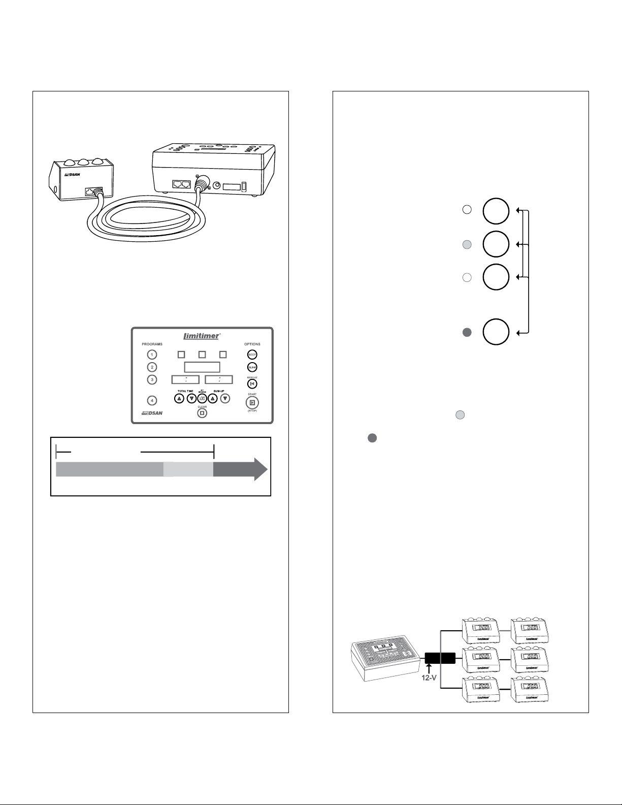
Quick Start - Set-up
(A) (B)
Using the Programs
Programs are useful for debates or contests
where pre-set timing formats can be selected
quickly or where timekeeping is separate for each
speaker.
To pre-set a
program, select that
program.
PROGRAMS
INDICATOR
CLOCK
1
STOP
Connect Signal Light to Limitimer with Cat-5 cable
or use the Cat-5–XLR adapter KES882 (included).
Plug in 12 V power supply (A).
Turn on power switch (B).
Set Total Time.
Set Sum-up Time.
Press Start.
TOTAL TIME
TALKTALK
START
SESSION
:
-
0:00
STOPSUM UP
Options: Beep - Blink
Set Total Time,
Sum-up Time, Blink
and Beep.
2
STOP
3
These settings are
saved for the
selected program.
SESSION
CONTINUE
4
Programs 1, 2, and 3 cannot run simultaneous
with each other. Toggling between these programs
stops the clock. Session 4 is a program that can
run in background to Program 1, 2 or 3.
A dimly-lit Program LED indicates that a
program is running in background. A brightly lit
LED indicates that the program is selected. A
signal light set to display multiple programs
displays the program selected on the timer.
Multiple Signal Lights
Note: Blink and beep settings, like time settings,
are set for each program individually.
Blink: Red light starts to blink after it comes on
Beep: Audible cue is sounded on yellow-to-red
light and on red blink
Blink + Beep: Audible cue is sounded on yellowto-red change, then, once every other second
when Red light starts to blink.
Note: Hold Beep button to activate a single
manual beep.
Up to 2 signal lights (PSL-20V or ASL2-ND3) can
be powered from the base timer at a distance of
about 200-feet. Longer distances will produce
power attenuation due to resistance in the cable.
To drive additional lights at greater distances, use
DSan model PSL-PB6 or PSL-PB18 power
distribution hubs with an appropriate power supply.
PSL-PB6
Page 3

Global Settings
Global settings are common to all programs. They are made on the 12-position DIP switch
on the rear of the timer console. The default settings (shown) are suitable for most uses.
1. Master / Slave.
When two or more timers are connected to one or
more signal lights, set one timer as master [ON]
and the other(s) as slave [OFF]. When only one
4. Count direction
Count-Down [ON] or Count-Up [OFF].
If Count-Up, Time Remaining display shows
elapsed time, else Time Remaining.
timer is used, it must be a master (default setting).
5. Count Behavior
Continue after zero [ON] else, stop display at zero.
Note, in OFF mode, internal clock continues to run
and red light stays on until user presses “ .”
6. Sound Volume
“Master” Switch 1 = ON “Slave” Switch 1 = OFF
The Slave timer acts as a client that sends
keystroke commands to control the Master and
display the Time Remaining. All the time
processing is done in the Master.
2. Counting Program 4 (Session)
Minutes:Seconds[ON]; Hours:Minutes [OFF]
When using Program 4 to time a program over
several hours, set to Hours:Minutes [OFF].
3. Counting Program 1, 2 or 3
Minutes:Seconds [ON] Hours:Minutes [OFF]
High [ON] Low [OFF]
7.+ 8. Sound Selection
7. ON 8. ON None*
7. OFF 8. ON Buzz
7. ON 8. OFF Ring
7. OFF 8. OFF Chime
*An empty sound. “ ”
pressed on the timer
outputs a cue to activate a
sound at a signal light that
is set for an audible sound.
9. Time Settings Permission
Allow time changes while clock is running [ON].
10. Block Transmitter [ON]
Model PRO-2000BT offers wireless transmission to
the remote signal light. Set to “OFF” when using a
wireless connection.
Default settings
on
1 2 3 4 5 6 7 8 9 10
STOP
BEEP
Wireless Operation
11 + 12. Wireless Channels (PRO-2000BT)
PRO-2000BT is equipped with an
integrated Bluetooth transceiver. It can ®
communicate with up to 6 Bluetooth signal
light receivers (TR-2000BT) or
other PRO-2000BT timers on
four different channels. This
allows multiple timer-signal
light networks to operate in
proximity. Match receiver
channel (rotary switch) with
timer channel (DIP switches 11
+ 12) as shown. Receiver channels Note:
5,6,7 0 not used. The effective distance for
60-feet. Bluetooth devices need to “find” one
TR-2000BT
Bluetooth
Connection LED
Page 4

Signal Light Settings
Signal Light Connections
Use DIP switches on the bottom of the signal light
to set which timer programs to display, whether
sound cues accompany light changes, which phase
lights are active and how the digital display
behaves. All settings are local can be different for
each signal light connected to the timer.
Default Settings
DIP switches on
bottom of signal light
on
1 2 3 4 5 6 7 8 9 10
Depressed position = ON
1-4. Select Timer Programs to be displayed
1. Display Program 1 [ON]
2. Display Program 2 [ON]
3. Display Program 3 [ON]
4. Display Program 4 [ON] (Session)
Since Program 4 can run in background, it might be
useful to use a separate signal light that is enabled
for Program 4 ONLY and another that is enabled for
Programs 1, 2 and/or 3 ONLY. A signal light that is
enabled for multiple programs displays the program
that is selected on the timer.
5. Continue counting after zero [ON] else, stop
display at zero. Note, in OFF mode, the internal
clock continues to run and red light stays on until
user presses “ .” Beep / Blink continue, if set.
STOP
6. Sound volume. High [ON] Low [OFF]
Connect the signal light to the Limitimer console
with the 50-foot Cat-5 cable or the Cat-5–XLR
adapter (both included). Maximum distance 200feet. This can be increased by using power
distribution hub PSL-PB6. See Page 1.
If Limitimer is used in debates or contests where
separate times are maintained for participants, set
the signal lights each to receive only a unique
program. Signal lights may be interconnected to
the timer console along a single cable run.
Program 1 Program 2
Caution: Cables carry 12V power.. Do not connect
to audio devices or data ports. Contact DSan for
pinouts to make your own cables.
7.+ 8. Sound Selection
7. ON 8. ON None*
7. OFF 8. ON Buzz
7. ON 8. OFF Ring
7. OFF 8. OFF Chime
*An empty sound. “Beep”
pressed on the timer
outputs a cue to activate a
sound at a signal light that
is set for an audible sound.
9. Display top lights [ON]
10. Display digits [ON]
Display lights:
Switch 9 =ON
Front lights
always active
Network Connections
Use IP-2000X “Network Extender” to make timersignal light connections over a network. For more
information, see www.dsan.com/Network .
Display digits:
Switch 10 = ON
 Loading...