

Page 1
User Manual
Version 2.01
The use of diagrams and illustrations in the manual are for reference only. The actual product may be different.
Product design and specifications are subject to change without notice
Professional LCDs
Page 2

DS652LR5 User Manual 1
Contents
Material Contents Declaration ................................................................................................................2
Recycling and Energy Information .........................................................................................................2
Declaration of Conformity.......................................................................................................................3
Safety Precautions .................................................................................................................................4
Safety Precautions .................................................................................................................................4
Important Safety Information ..................................................................................................................5
Getting Started .......................................................................................................................................6
Contents .............................................................................................................................................6
Installing and Replacing Remote Control Batteries............................................................................6
Installation...............................................................................................................................................7
Mounting.............................................................................................................................................7
Wall Mounting...................................................................................................................................10
Connecting to a Power Source.........................................................................................................10
Connecting an External Video Source .............................................................................................10
Connecting Multiple Displays for Video Wall Applications ...............................................................11
Connector Positions .........................................................................................................................13
Input / Output Terminals...................................................................................................................14
Operating Instructions ..........................................................................................................................15
Powering On/Off the Display ............................................................................................................15
Using the Remote Control ................................................................................................................15
Using the Rear Panel Controls.........................................................................................................18
Navigating the On Screen Display (OSD) Menu..................................................................................19
Specifications .......................................................................................................................................24
Input Mode............................................................................................................................................25
Pin Assignments...................................................................................................................................26
Digital RGB Output (DVI-D): DVI......................................................................................................26
Digital RGB Input (DVI-D): DVI ........................................................................................................26
RS-232 Output..................................................................................................................................27
RS-232 Input ....................................................................................................................................27
Troubleshooting....................................................................................................................................28
Installation Notes..................................................................................................................................29
Handling............................................................................................................................................29
Unboxing the Display........................................................................................................................31
Hanging From a Ceiling....................................................................................................................33
Operation Temperature ....................................................................................................................34
Ventilation (Fan-cooled models).......................................................................................................35
Enclosures........................................................................................................................................36
Using a Cooling & Heater Solution...................................................................................................36
In-Window Applications ....................................................................................................................38
Media Player Location......................................................................................................................39
Network User Interface.........................................................................................................................40
Page 3
DS652LR5 User Manual 2
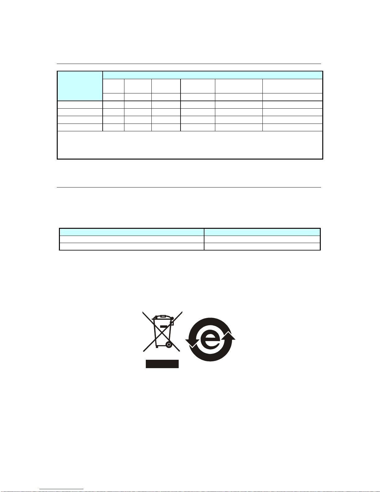
Material Contents Declaration
Hazardous Substances
Lead Mercury Cadmium
Hexavalent
Chromium
Polybrominated
Biphenyls
Polybromodiphenyl
Ethers
Part Name
Pb Hg Cd Cr6+ PBB PBDE
PCBA
O O O O O O
CHASSIS
O O O O O O
ACCESSORY
O O O O O O
PACKAGE
O O O O O O
“O” indicates that the level of the specified chemical substance is less than the threshold level
specified in the standards of SJ/T-11363-2006 and EU 2005/618/EC.
“
” indicates that the level of the specified chemical substance exceeds the threshold level specified
in the standards of SJ/T-11363-2006 and EU 2005/618/EC.
Recycling and Energy Information
DynaScan is firmly committed to its environmental protection efforts and we believe that reducing our
products’ impact on the environment is of the utmost importance. We are dedicated to meet the
latest environmental protection regulations.
Energy usage
Mode Energy Consumption
Normal Max. 740 W
Standby < 1 W
Disposal
Do not dispose of electrical appliances as unsorted municipal waste, use separate collection facilities.
Contact your local government for information regarding the collection systems available. If electrical
appliances are disposed of in landfills or dumps, hazardous substances can leak into the groundwater
and get into the food chain, damaging your health and well-being. When replacing old appliances
with new one, the retailer is legally obligated to take back your old appliances for disposal at least for
free of charge.
Page 4
DS652LR5 User Manual 3
Declaration of Conformity
FCC Verification
This device complies with Part 15 of the FCC Rules. Operation is subject to the following two
conditions: (1) this device may not cause harmful interference, and (2) this device must accept any
interference received, including interference that may cause undesired operation.
FCC Information
This equipment has been tested and found to comply with the limits for a Class A digital device,
pursuant to Part 15 of the FCC Rules. These limits are designed to provide reasonable protection
against harmful interference when the equipment is operated in a commercial environment. This
equipment generates, uses, and can radiate radio frequency energy and, if not installed and used in
accordance with the instruction manual, may cause harmful interference to radio communications.
Operation of this equipment in a residential area is likely to cause harmful interference in which case
the user will be required to correct the interference at his own expense.
Declaration of the Manufacturer
We hereby certify that the Professional LCD DS652LR5 is in
compliance with
Low Voltage Directive 2006/95/EC
Electromagnetic Compatibility Directive 2004 /108 /EC
IEC 60950-1:2005 (2nd Edition) +Am1:2009
EN 60950-1:2006+A11:2009+Am1:2010+A12:2011
EN 55022:2010+AC:2011 Class A ITE
EN 61000-3-2:2006+A1:2009+A2:2009
EN 61000-3-3:2008
EN 55024:2010
EN 61000-4-2:2009
EN 61000-4-3:2006+A1:2008+A2:2010
EN 61000-4-4:2012
EN 61000-4-5:2006
EN 61000-4-6:2009
EN 61000-4-8 :2010
EN 61000-4-11:2004
DynaScan Technology,
Inc.
VCCI report ready.
VCCI Class A ITE
V-3/ 2013.04 Technical Requirements
V-4/ 2012.04 Supplementary Test Conditions for Equipment under
Test
Page 5
DS652LR5 User Manual 4
Safety Precautions
CAUTION
Do not install the display in a wet environment or place anything filled with liquid
such as a vase or beverage on top of it.
Do not install the display near flammable objects such as gasoline or other
volatile liquids.
Do not install the display near any heat sources such as radiators or other
heating devices.
Do not install the display in the dusty environment.
Do not damage the power cord or plug.
Do not disassemble the screen to avoid electric shock.
The product can normally be operated at an altitude under 2000m. Abnormalities
may occur when installing the device at an altitude above 2000m.
WARNING
The heat sink behind the screen may be hot after extensive use. Do not touch it
to avoid being burned.
Do not touch the screen panel with sharp objects or extreme pressure to avoid
damaging the panel.
The display should be installed in well-ventilated place, do not install it in a
confined space.
Do not drop or allow any objects to fall on the screen.
Do not touch the screen with wet hands to avoid electric shock.
Unplug the power cord before cleaning the device. Use a soft and dry cloth to
wipe the screen off. Do not use alcohol or other chemical liquids.
If you smell smoke or hear strange noises, immediately unplug the monitor and
contact the vendor.
Do not discard this product with general household waste. Be sure to comply with
the local waste regulations for disposal.
Suitable for mounting on concrete and non-combustible surface only.
IMAGE BURN-IN WARNING
When a stationary or fixed image is displayed on the screen for a long time, the
image may be permanently imprinted on the screen. This phenomenon is
known as image burn-in and is not covered by the manufacturer's warranty.
In order to avoid burn-in, avoid prolonged display of static or fixed images on the
screen.
Page 6

DS652LR5 User Manual 5
Important Safety Information
• Disassembling the LCD is strictly prohibited. Opening the cover may expose the user to electric
shock or other hazards. Please contact DynaScan certified service professionals for all
maintenance requirements.
• Do not allow any liquid to enter the LCD. Also avoid placing the LCD close to water sources.
• Do not place heavy objects on the power cord. A damaged power cord might cause electric
shock or fire.
• Do not bend, twist, or damage the power cord.
• The power cord must comply with the local safety regulations.
• Do not damage or modify the prongs/pins and the ground contact on the power cord plug.
• Do not place the LCD on an unleveled surface or an unstable vehicle. The LCD could fall over
and cause substantial damage.
• Do not cover the vents and/or the heat sink.
• Do not install the LCD beside radiators or other heat sources. The installation site should have
sufficient ventilation so the heat generated by the LCD can be dissipated.
• Do not use the Signage in a hot, humid, dusty, or fumy environment.
• Handle the LCD with care. Save the packaging materials for transport later.
• Clean the LCD backside at least once a month for dust and other particles.
Unplug the LCD immediately and contact a DynaScan certified service professional as soon as
possible when any of the following situations occurs:
• Damaged power cord or power plug.
• If liquid or foreign object has entered the LCD.
• If the LCD has been exposed to rain or water.
• If the LCD has been dropped or the casing has become damaged.
• If any structural damage such as cracks or unnatural vibration is found.
• If the LCD cannot be operated following the steps outlined in this manual.
• If the LCD emits smoke or other odors, or generates strange noises.
Operating Suggestions
• Avoid displaying a stationary image for a long period of time in order to prevent image sticking.
Cleaning the Panel
• Use a soft, lint-free cloth to gently wipe the dust off from the screen panel.
• Do not use any hard material to wipe the panel.
• Do not poke the panel with your hand or any sharp object (such as a pen or a nail) or exert
excessive pressure on the panel to prevent any damage.
• Do not use any cleaning solutions on the panel as it might cause discoloration.
Cleaning the Casing
• Unplug the power cord.
• Gently wipe the casing with a soft cloth.
Attention
• Do not use any of the following solutions to clean the casing as they may damage the paint and
cause it to crack or peel: benzene solution, alkaline solution, alcohol-based cleaning solution,
glass cleaner, wax, polisher, or detergent.
Page 7
DS652LR5 User Manual 6
Getting Started
Contents
Confirm that the accessories below are shipped along with the display. If any item is missing, please
contact your dealer. The color and shape of the accessories may vary with the products.
• DS652LR5 Professional LCD.
• Remote Control x 1 pc.
• Batteries (1.5V / AAA) x2 pcs.
• Quick Start Guide x1 pc.
• Power cable x1 pc.
• RS-232 cable x1 pc.
• DVI cable x1 pc.
• Ethernet crossover cable x1 pc.
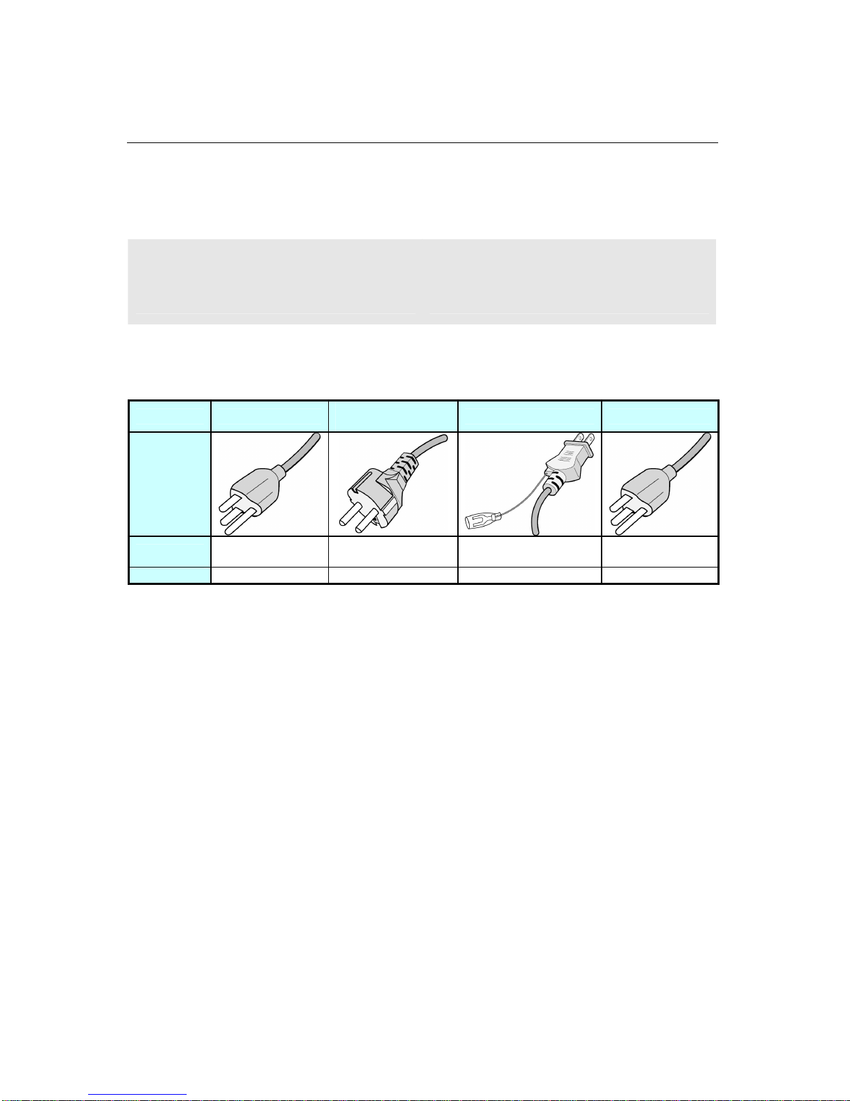
Attention: Please use the following table to check whether the included power cord is suitable for your
region. If the power cord does not match your region, please contact your local supplier. Please
use matching AC socket in order to meet your local safety regulations.
Plug Type North America
European
Continental
Japan Taiwan
Plug
Shape
Region
U.S.A. / Canada
EU
(Except U.K.)
Japan Taiwan
Voltage
120V 230V 100V 110V
Installing and Replacing Remote Control Batteries
1. Open the battery compartment cover.
2. Insert 2 new AAA batteries.
3. Close the battery compartment cover.
Warning:
• Incorrect usage of batteries may cause leakage or explosion.
• Pay attention to the polarity when installing the batteries.
• Do not mix different types of batteries or new and used batteries. Doing so may shorten the
battery life or cause leakage.
• Remove or replace the batteries when they are empty in order to prevent acid leaking in the
battery compartment.
• Do not touch the leaked substance from the batteries in case of a battery leakage. Doing so
may hurt human skin.
Note: If the remote control is not going to be used for a long time, we recommend removing the
batteries from the remote control.
Page 8
DS652LR5 User Manual 7
Installation
The LCD must be properly installed using a wall mount. Incorrect installation may cause injury or
damage the equipment. Product warranty does not cover the damage caused by improper
installation and DynaScan shall not be held responsible in such incident. Refer to the mount
manufacturer’s instructions for proper installation.
Mounting
• Hanging the Professional LCD from the ceiling or mounting it on the wall is the responsibility of
the user. Not all ceilings or walls provide enough strength to support the LCD. The LCD may
drop and cause serious injury if it is hanging from the ceiling with insufficient support or is
mounted on a slanted wall. Product warranty does not cover improper installation, modification,
or damage caused by natural disasters. DynaScan recommends having certified professionals
to evaluate the installation site and perform the mounting operation.
• Do not to cover the vent and/or the heat sink in order to ensure proper heat dissipation.
• Refer to the installation guide provided by the manufacturer for proper mounting.
When mounting on a wall or hanging from a ceiling
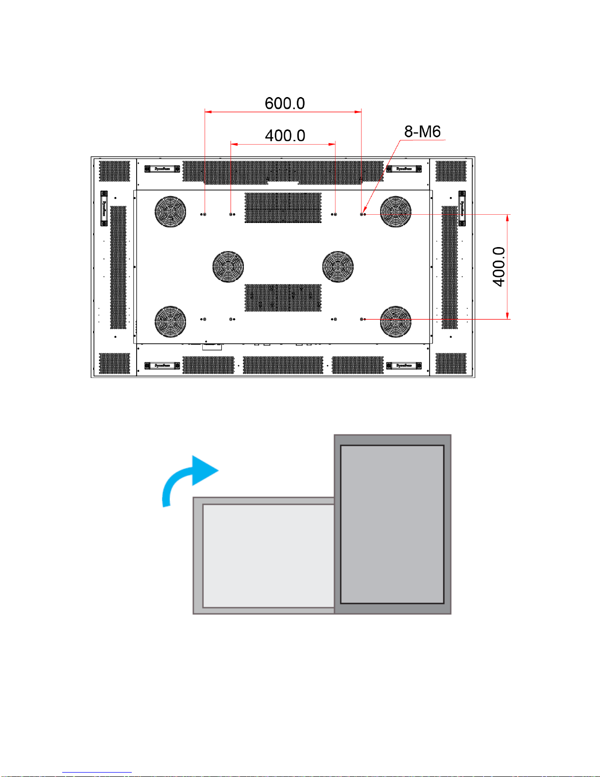
• A wall mount is not included in the accessory. Please purchase a VESA Standard wall mount to
secure the LCD. DynaScan is not responsible for the damage caused by using non-standard
wall mounts.
• Verify that the mounting location can support the weight of the LCD before installation.
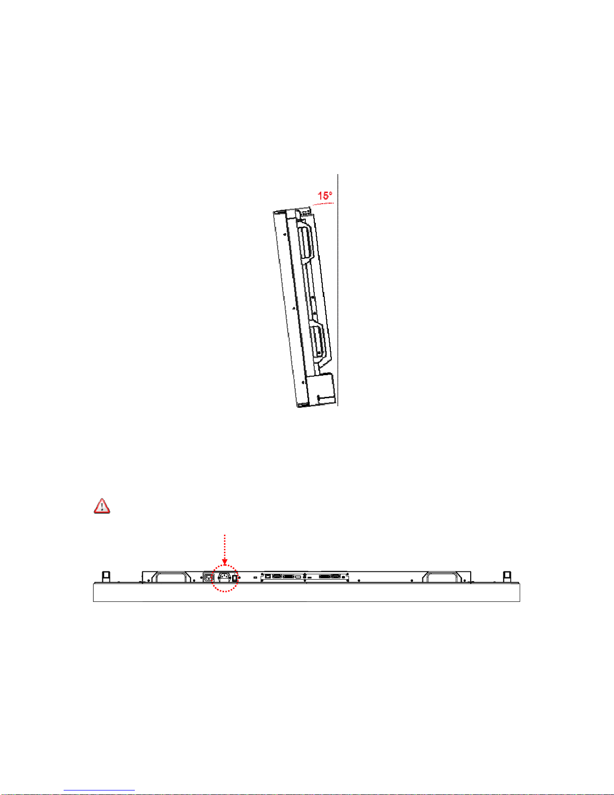
• The installation angle must be within 15 degrees of the vertical axis.
• Do not install the wall mount while the power is turned on as it may cause serious injury due to
electrical shock.
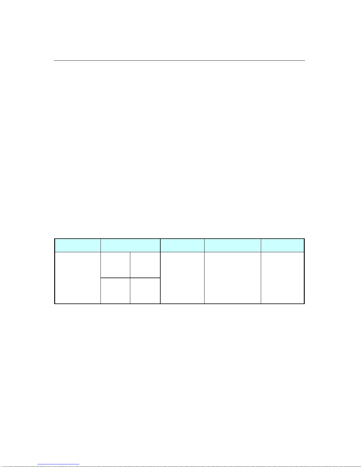
Model Number
VESA (mm)
Screw
Specification
Screw Length Number
(A * B) 400 * 400
DS652LR5
(A * C) 400 * 600
M6
Greater than 10mm
Smaller than 12mm
(not including wall
mount thickness)
8
Page 9
DS652LR5 User Manual 8
DS652LR5
Orientation
• When used in the portrait orientation, the LCD should be rotated clockwise when looking at the
front of the display such that the left edge becomes the top edge.
Portrait mode: Rotate the set clockwise 90° (mandat ory)
Installation Location
• The wall and mount must have enough strength to support the LCD and its accessories.
• Do not install in a location with strong vibrations or is dusty.
• Do not install near the building’s main electric panel.
• Ensure the LCD is secured in such a manner that it cannot be easily removed by the general
public.
A
B
Unit: mm
C
Page 10
DS652LR5 User Manual 9
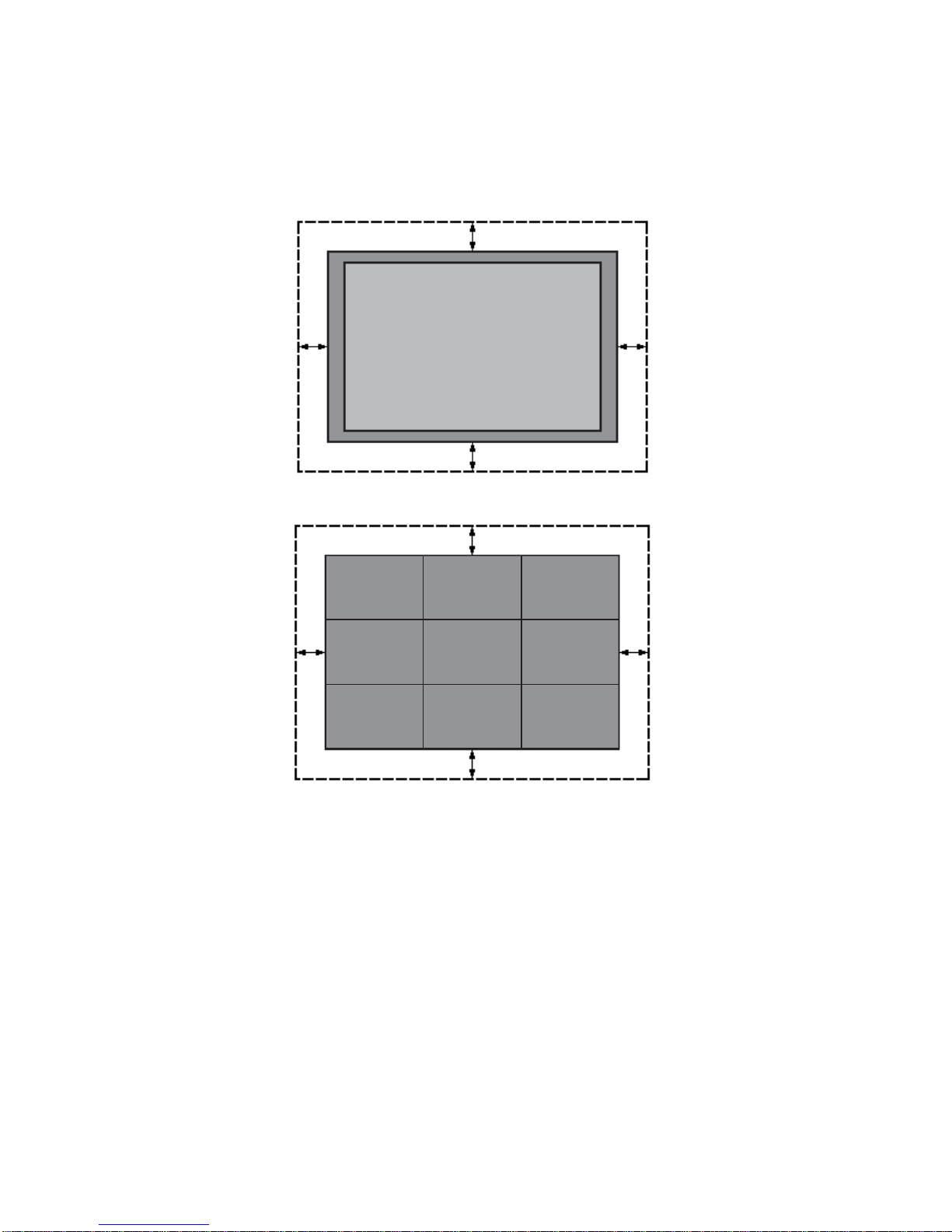
• Leave clearance around the outer edge of the LCD (or video wall matrix) from other objects to
ensure proper ventilation.
• For installations with screens inset into the wall, refer to section: 錯誤! 找不到參照來源。 for
cooling and ventilation considerations.
Single display
Video wall
When hanging from a ceiling
• Ensure that the ceiling is strong enough to support the LCD and it accessories. Earthquake,
unexpected vibration and other external forces should be taken into consideration when
evaluating the ceiling strength.
• The LCD should be secured to the building’s structural frame such as a beam rather than light
steel frame or interior decoration.
• Do not use wood screws or dry wall anchors for installation.
Maintenance
• Inspect the fasteners regularly for signs of loosening or deformation. Please perform
appropriate corrective measures when a problem is identified. Neglecting the problem may
worsen the situation.
• Increase the inspection frequency on areas where previous maintenance had occurred to ensure
the problems do not occur again.
Page 11
DS652LR5 User Manual 10
Wall Mounting
• A wall mount is not included. Please purchase a VESA Standard wall mount to secure the LCD.
DynaScan is not responsible for damages caused by using non-standard wall mounts.
• Verify that the mounting location can support the weight of the LCD before installation.
• The installation angle must be within 15 degrees of the vertical axis.
• Do not install the wall mount while the power is turned on as it may cause serious injury from
electrical shock
Connecting to a Power Source
Using the power cable provided, plug it in the power inlet on the back of the display shown in the
diagram below. Connect the power cable to a 110-220 volt, 50 / 60Hz AC power outlet.
Insert the plug completely into the socket. A loose power connection may cause damage to the
display and/or lead to a fire hazard.
Connecting an External Video Source
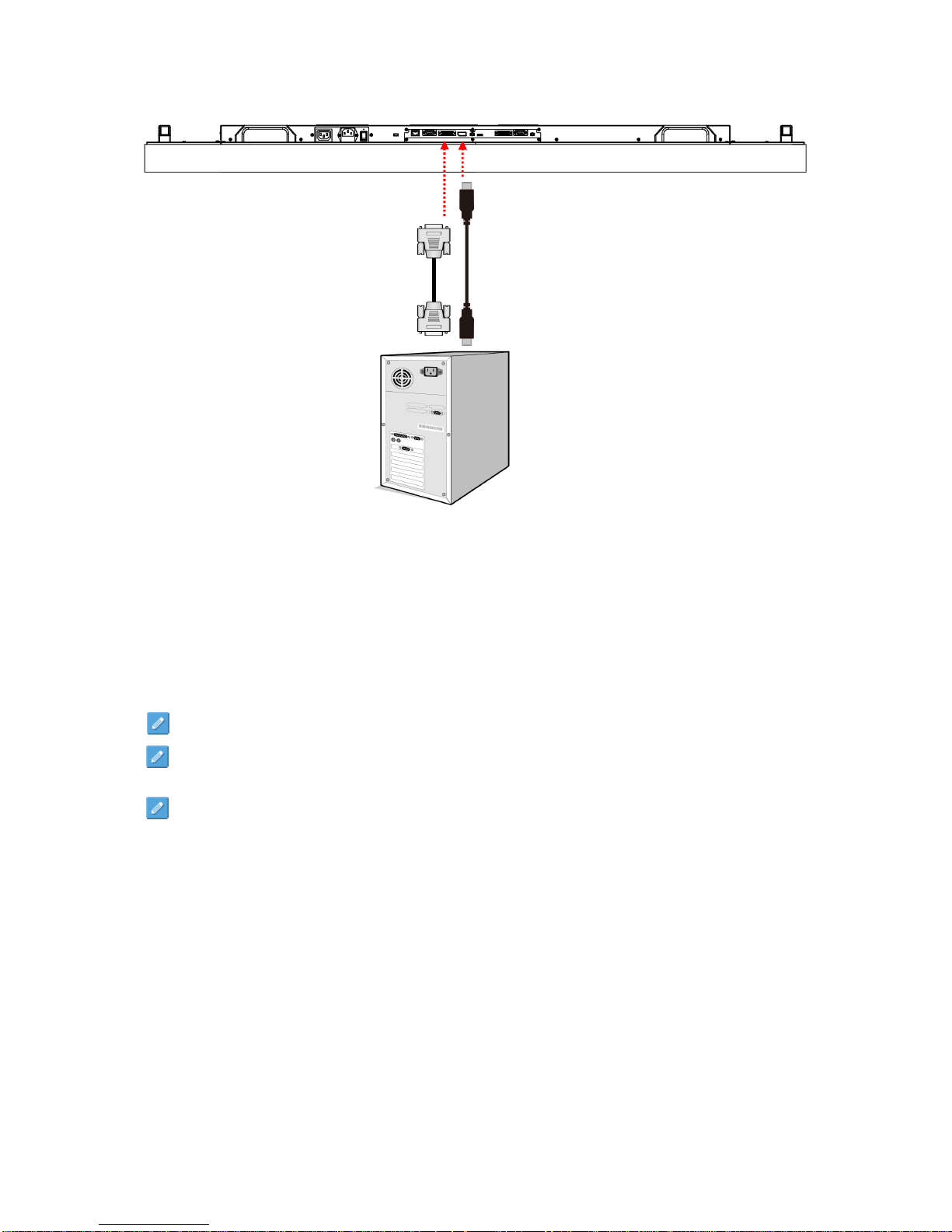
Turn OFF the power of both LCD and external video device. Using the DVI cable (or DP cable)
provided, insert one end into the DVI-IN (or DP-IN) on the back of the display shown the in the diagram
below. Connect the other end of the DVI cable (or DP cable) to the DVI output (or DP output) of the
video source. Refer to your video device’s manual for additional information.
Page 12
DS652LR5 User Manual 11
Connecting Multiple Displays for Video Wall Applications
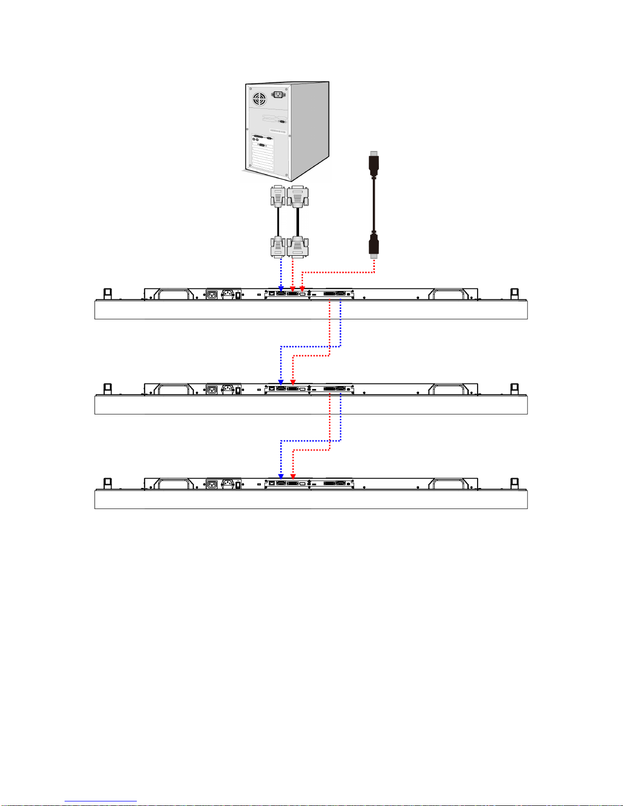
To daisy chain multiple displays for a video wall application, connect a video source to the 1st display
into the chain with the supplied DVI cable (or DP cable) and RS-232 cable. Connect the DVI-OUT of
the 1st display to the DVI-IN of the 2nd display. Using the RS-232 cable provided, connect the RS-232
OUT of the 1st display to the RS-232 IN of the 2nd display. Repeat the connection for the remaining
displays. Use the OSD Menu or Display Manager software to configure the size of the video wall and
the position of each display.
Note: The maximum number of DS652LR5’s in a Video Wall is 36.
Note: The DynaScan “Display Manager” application is required to be installed on the PC in order
to use the External Control feature.
Note: The Daisy Chain Setting (video wall function) only supports a resolution of 1920 x 1080
(1080p).
DVI Cable
DVI (IN)
DVI (OUT)
DP Cable
DP (IN)
DP (OUT)
Page 13
DS652LR5 User Manual 12
DISPLAY 1
DISPLAY 2
DISPLAY 3
DVI (OUT)
DVI (IN)
DVI (IN)
RS-232 (OUT)
RS-232 (IN)
Video Source
RS-232 (IN)
DVI (OUT) RS-232 (OUT)
or DP (IN)
or DP (OUT)
DVI (OUT)
DVI (IN)
RS-232 (OUT)
RS-232 (IN)
Page 14
DS652LR5 User Manual 13
Connector Positions
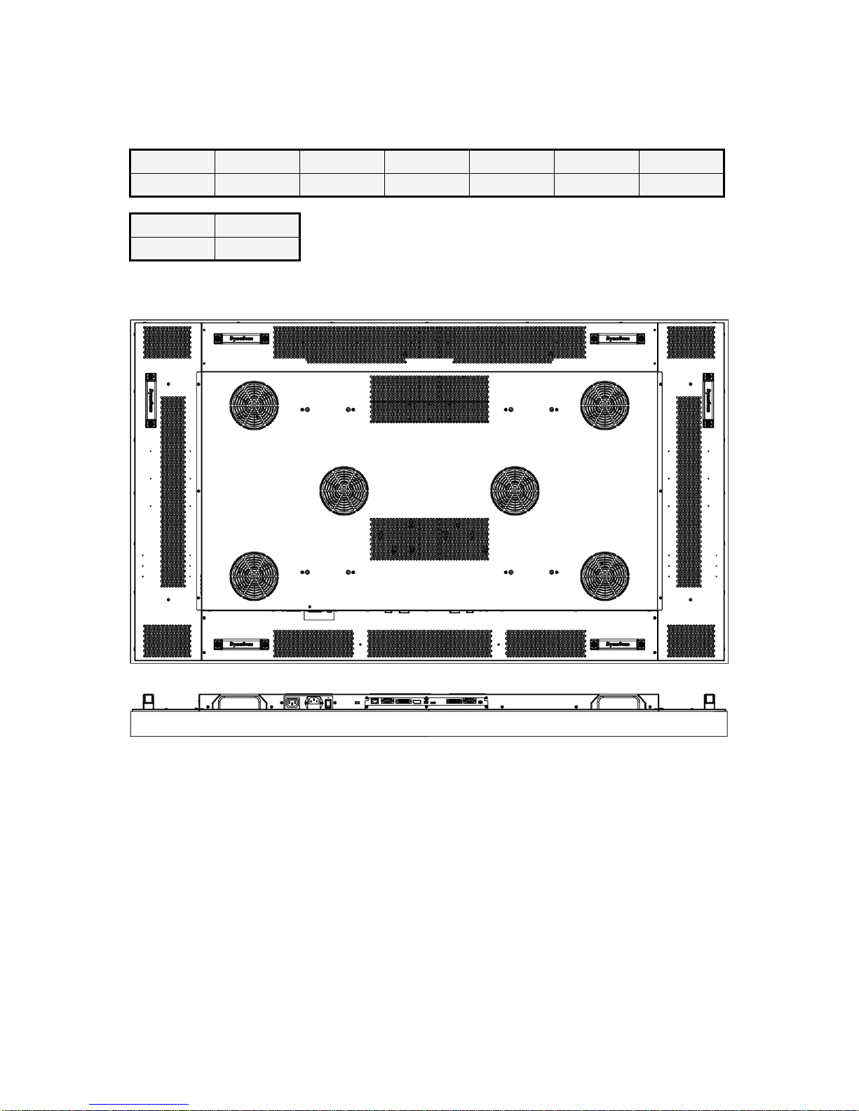
AC (OUT) AC (IN)
Power Switch
RJ-45(IN)
RS-232 (IN)
DVI (IN)
DP (IN)
DVI (OUT) RS-232 (OUT)
DS652LR5
U
nit: m
m
Page 15
DS652LR5 User Manual 14
Input / Output Terminals
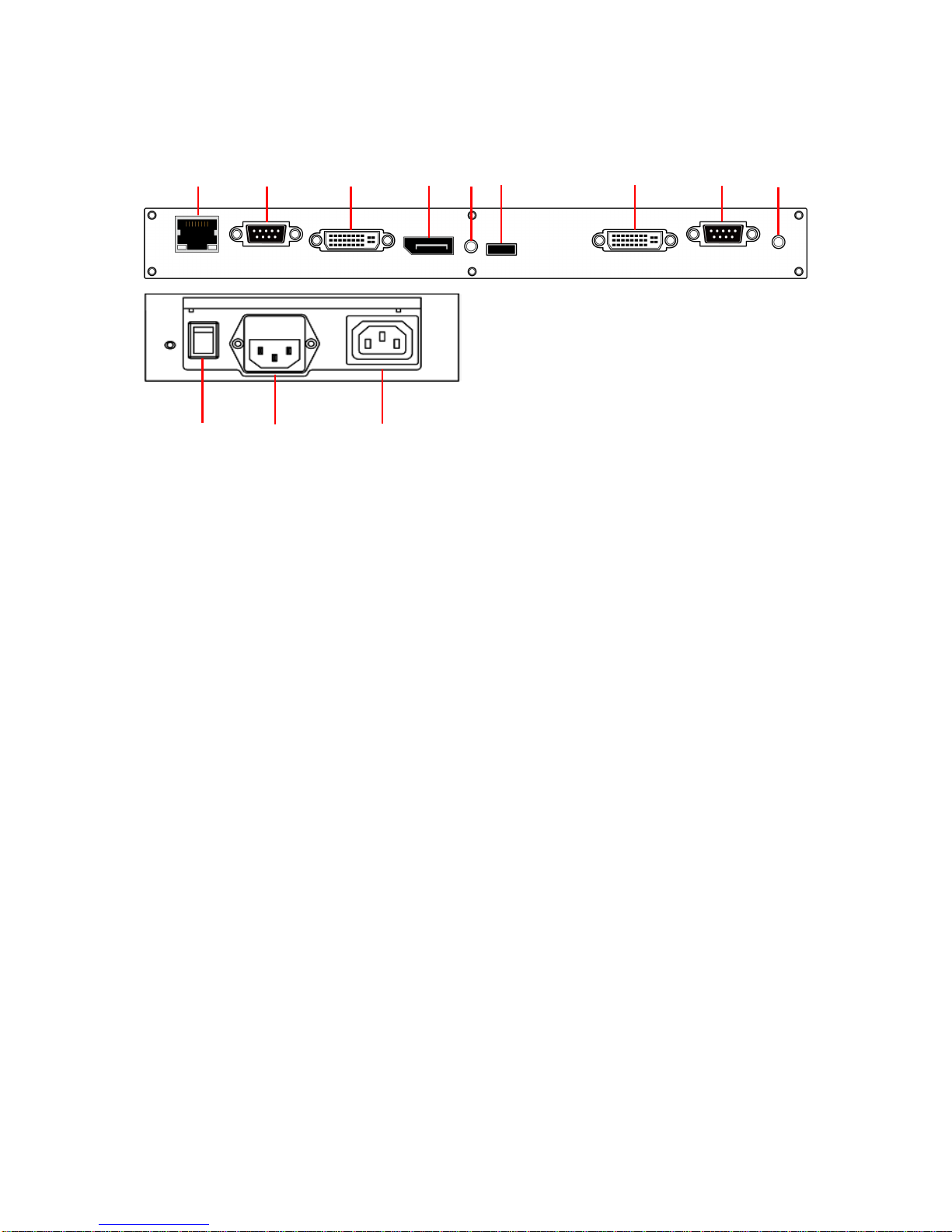
1. RJ-45 (IN): RJ45 network input connection for remote control from PC.
2. RS-232 (IN): RS232C network input connection for remote control from PC.
3. DVI (IN): Connect the DVI-D output of a PC, or the HDMI output of an AV device via a
DVI-HDMI cable.
4. DP (IN): Connect the DP output of a PC, or the DP output of an AV device via a DP cable.
5. Audio (IN): Connect the audio input from an external AV device.
6. Extension Connector: Extension Connector for optional IR Extension sensor kit (ESK201).
7. DVI (OUT): Output the signal from DVI IN.
8. RS-232 (OUT): RS232 control function for daisy chain application.
9. Audio (OUT): Connect the audio signal output from Audio IN jack to an external AV device.
10. Power Switch: Press to switch the main power on/off.
11. AC (IN): Connect the supplied power cord to the wall outlet.
12. AC (OUT): AC outlet 110~220V up to 100 Watt.
○
6
○
7
○
8
○
10
○
11
○
5
○
4
○
3
○
2
○
1
○
9
⑫
Page 16
DS652LR5 User Manual 15
Operating Instructions
Powering On/Off the Display
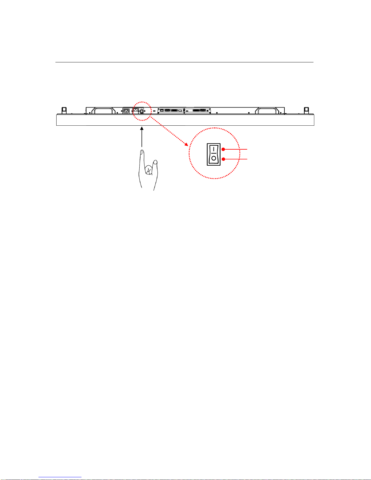
To turn on/off the display, press the power switch on the back of the display as shown in the diagram
below.
Using the Remote Control
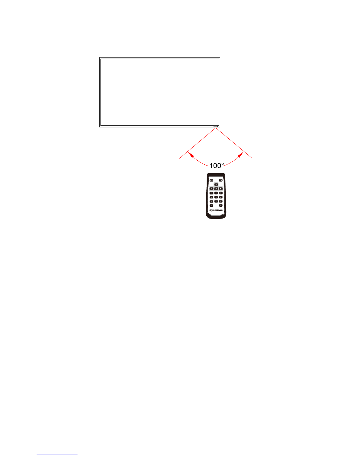
When using the remote control, aim the remote at the IR receiver on the display. The IR receiver on
the DS652LR5 model is at the rear of the display with a receiving angle of 100 degrees. The IR
receiver configurations of the model are shown in the figure below.
The operating range of the remote control is 2.5 meters (8 feet).
Ambient light may affect the performance of the remote control. Avoid fluorescent or neon lights in the
vicinity.
N
OTE
:
The remote control only works
when the power switch is ON.
OFF
ON
Page 17
DS652LR5 User Manual 16
DS652LR5
Page 18
DS652LR5 User Manual 17
Using the Remote Control (cont.)
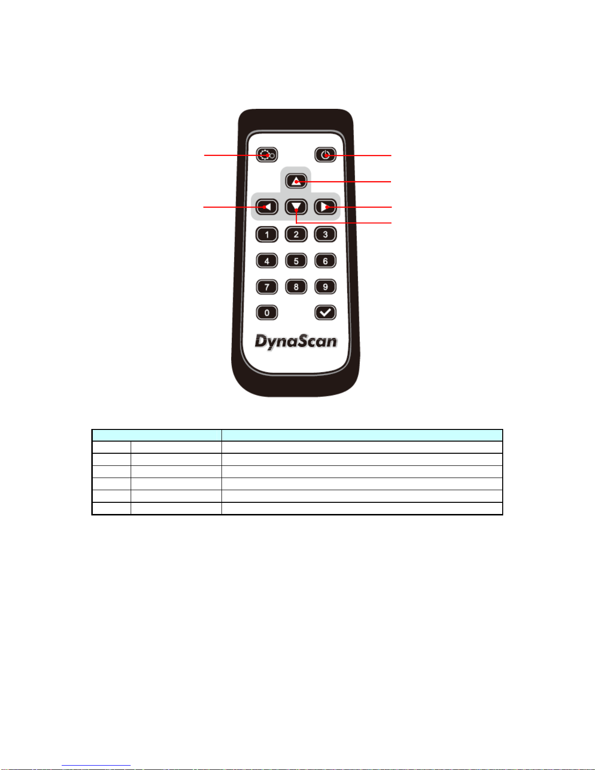
Color and shape may vary by model.
ITEM DESCRIPTION
POWER Power On / Off
MENU OSD On / Off
UP Move the cursor up or change the setting of selected item.
LEFT Exit the current selection.
RIGHT Select the highlighted item.
DOWN Move the cursor down or change the setting of selected item.
Page 19
DS652LR5 User Manual 18
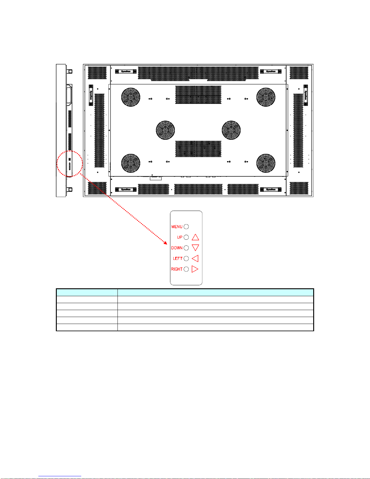
Using the Rear Panel Controls
ITEM DESCRIPTION
MENU OSD On / Off, Power On / Off.
UP Move the cursor up or change the setting of selected item.
DOWN Move the cursor down or change the setting of selected item.
LEFT Exit the current selection.
RIGHT Select the highlighted item.
Page 20
DS652LR5 User Manual 19
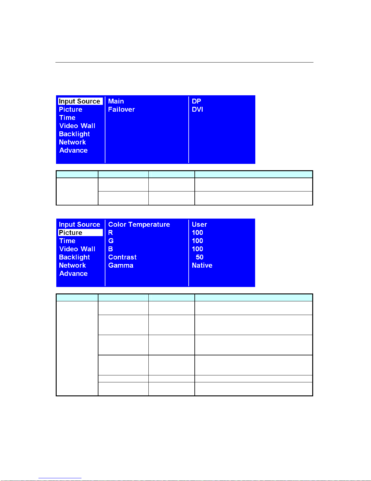
Navigating the On Screen Display (OSD) Menu
Press the MENU button on either the rear panel control or remote control to show the OSD. Use the
navigation arrows to select and adjust the menu items.
ITEM 1 ITEM 2 DEFAULT DESCRIPTION
Main DP
Set the Main input to display. (DP(Display
Port) or DVI)
Input Source
Failover DVI
Set the Failover input to display.
(DP(Display Port) or DVI)
ITEM 1 ITEM 2 DEFAULT DESCRIPTION
Color
Temperature
D65
Select the color temperature. (User, D93,
D65 and D55).
R 100
Adjust the red light level. Range 0 – 100.
Note: The feature is only supported on User
mode.
G 100
Adjust the green light level. Range 0 – 100.
Note: The feature is only supported on User
mode.
B 100
Adjust the blue light level. Range 0 – 100.
Note: The feature is only supported on User
mode.
Contrast 50 Adjust the contrast level. Range 0 – 100.
Picture
Gamma Native
Adjusts the Gamma value. (Native, 2.2, 2.4
and sgamma)
Page 21
DS652LR5 User Manual 20
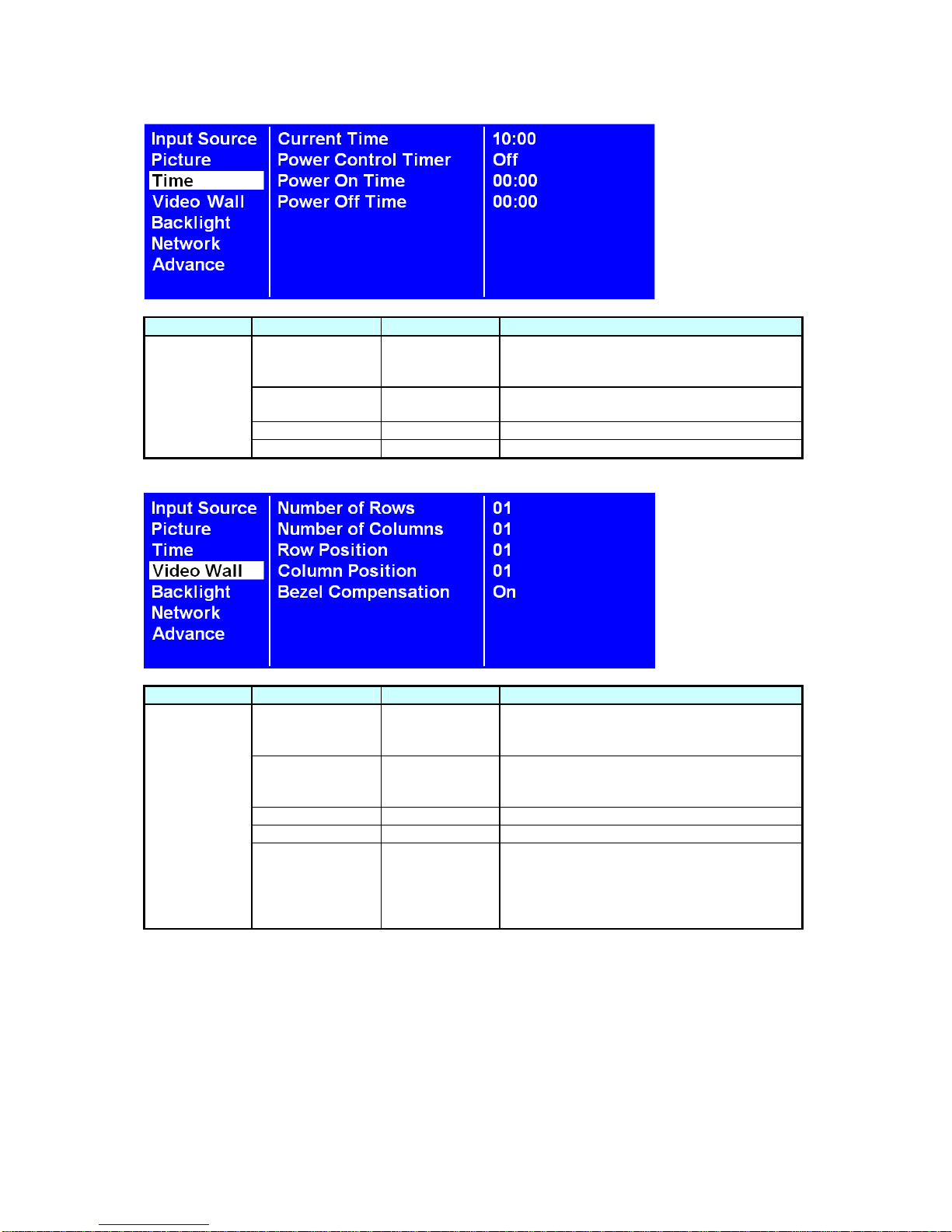
ITEM 1 ITEM 2 DEFAULT DESCRIPTION
Current Time HH:MM
Set the clock.
Note: The internal clock will continue to
function when the power is turned off.
Power Control
Timer
Off
Turn on / off automatic power schedule
function.
Power On Time HH:MM Set turn-on time.
Time
Power Off Time HH:MM Set turn-off time.
ITEM 1 ITEM 2 DEFAULT DESCRIPTION
Number of Rows 1
Set number of rows in a video wall.
Note: The maximum number of rows in a
daisy chain is 15.
Number of
Columns
1
Set number of columns in a video wall.
Note: The maximum number of columns in a
daisy chain is 15.
Row Position 1 Vertical position in a video wall.
Column Position 1 Horizontal position in a video wall.
Video Wall
Bezel
Compensation
On
Choose to turn the frame compensation
function on or off. When turned on, the
display will adjust the image to compensate
the width of display bezels in order to
accurately display the image.
Page 22
DS652LR5 User Manual 21
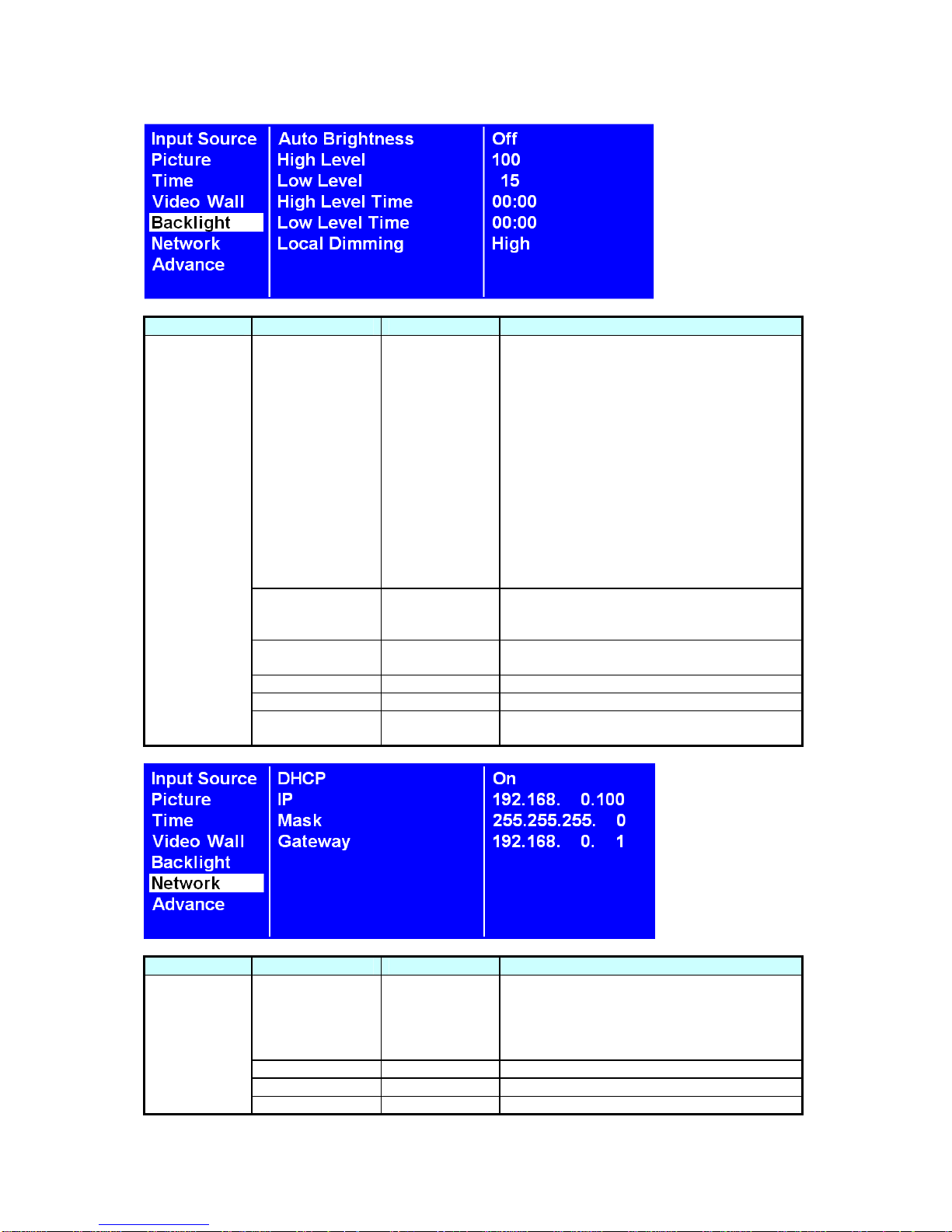
ITEM 1 ITEM 2 DEFAULT DESCRIPTION
Auto Brightness Off
To turn On / Off the auto brightness
adjustment.
Note: If the AUTO BRIGHTNESS is off, the
screen brightness will remain at HIGH
LEVEL brightness value. If the AUTO
BRIGHTNESS is on (Auto), the display
brightness adjusts according to the ambient
light. When ambient light is bright, the
screen will adjust to the HIGH LEVEL
brightness value set; when ambient light is
dark, the screen will adjust to the LOW
LEVEL brightness value set. When the
Timer mode is set, the display will
automatically switch the brightness
according to the time set.
High Level 100
Adjusts the highest brightness level.
Range 0 – 100.
Low Level 15
Adjusts the lowest brightness level.
Range 0 – 100.
High Level Time HH:MM Set high level time.
Low Level Time HH:MM Set low level time.
Backlight
Local Dimming High
Adjusts the contrast. High is the highest
contrast. Off is the lowest contrast.
ITEM 1 ITEM 2 DEFAULT DESCRIPTION
DHCP On
Choose to enable or disable the DHCP
function. If enabled, the display will assign
the IP address, Subnet mask and Default
gateway automatically. If disabled, the
following values will be entered manually.
IP 192.168.0.100 Assign IP address.
Mask 255.255.255.0 Assign Subnet mask.
Network
Gateway 192.168.0.1 Assign Default gateway.
Page 23
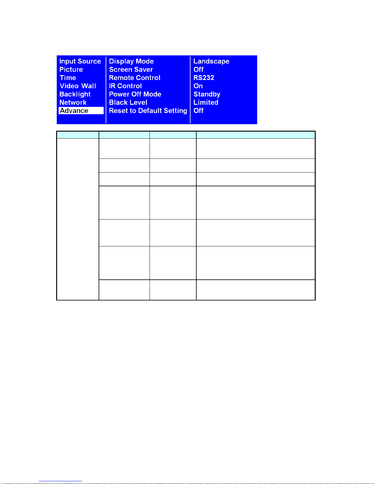
DS652LR5 User Manual 22
ITEM 1 ITEM 2 DEFAULT DESCRIPTION
Display Mode Landscape
Change the Menu orientation. The Menu
can be displayed in either LANDSCAPE or
PORTRAIT mode.
Screen Saver Off
Turn on / off image burn-in protection.
Set image burn-in protection interval.
Remote Control RS232
Choose to use the remote control function
RS232 or Network.
IR Control On
Enable/disable the remote control for Menu.
Note: When disabled, the remote control
function can be enabled again from the
control panel on the display or through the
DynaScan “Display Manager” application.
Power Off Mode Standby
When in Power Off Mode, RS-232 controls
do not function. Only [Main Power Switch]
on the display or [Power Button] on the
remote control can wake up the display.
Black Level Limited
Selects the black level to adjust the screen
gray scale. "Limited" for video source uses
16 to 235 levels for R/G/B, such as HDMI.
"RGB Full" for video source uses all levels
from 0 to 255 levels.
Advance
Reset to Default
Setting
Off
Restore all settings to default.
Note: It does not modify CURRENT TIME,
POWER ON TIME and POWER OFF TIME.
Page 24
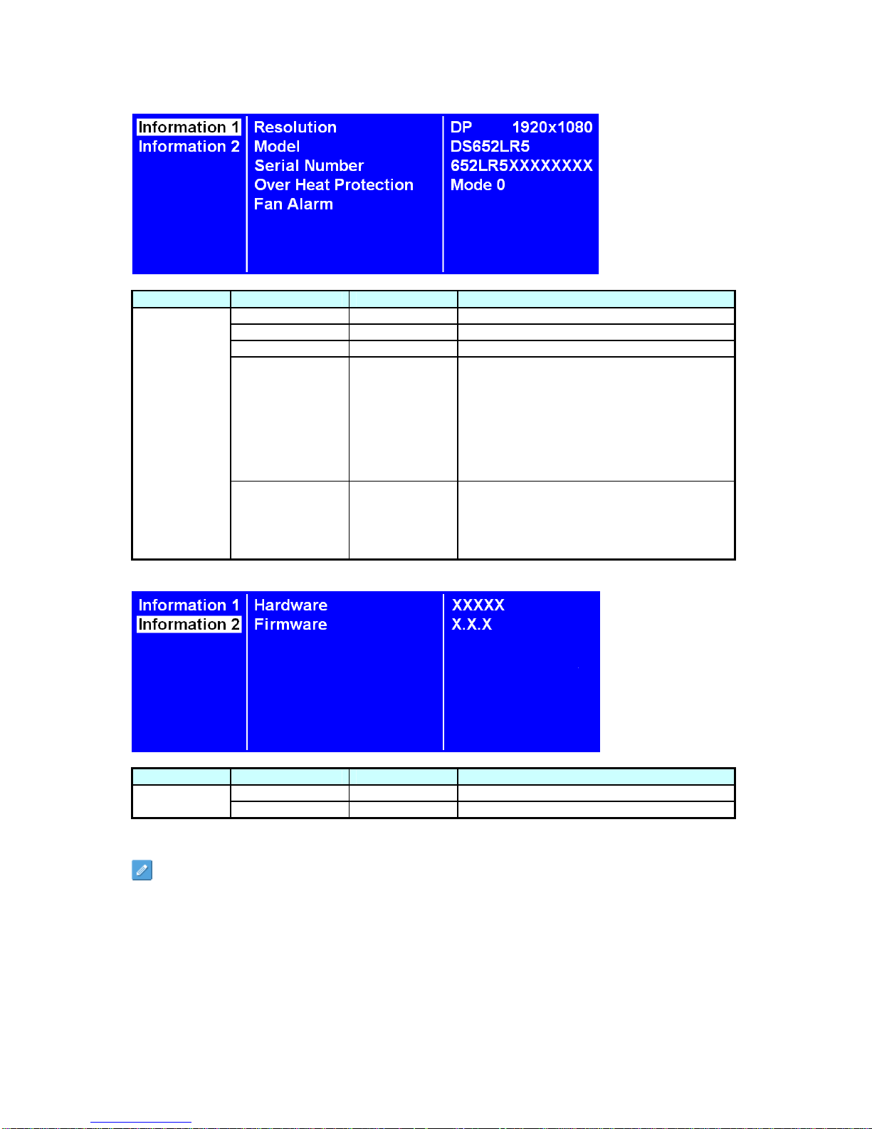
DS652LR5 User Manual 23
ITEM 1 ITEM 2 DEFAULT DESCRIPTION
Resolution 1920x1080 Input resolution.
Model DS652LR5 The display’s model.
Serial Number The display’s serial number.
Over Heat
Protection
Not displayed
It will enter into protection mode when the
display internal temperature is over heat.
Mode 0 = Brightness 50%.
Mode 1 = Brightness 25%.
Mode 2 = Brightness 03%.
When the temperature is decreased to exit
the protection, the brightness will restore to
100% and Over Heat Protection is disabled.
Information 1
Fan Alarm Not displayed
When any of the cooling fans on the display
rear side is failure and stops running, the
Fan Alarm will appear and blink, and reduce
the brightness to 25%. Be sure to contact
the service engineer for repair.
ITEM 1 ITEM 2 DEFAULT DESCRIPTION
Hardware The H/W version.
Information 2
Firmware The F/W version.
Some functions may not be available for all models.
*Adjusted value: Each R/G/B value for this product has been individually adjusted during production to
a preset color temperature of 6500K.
Page 25
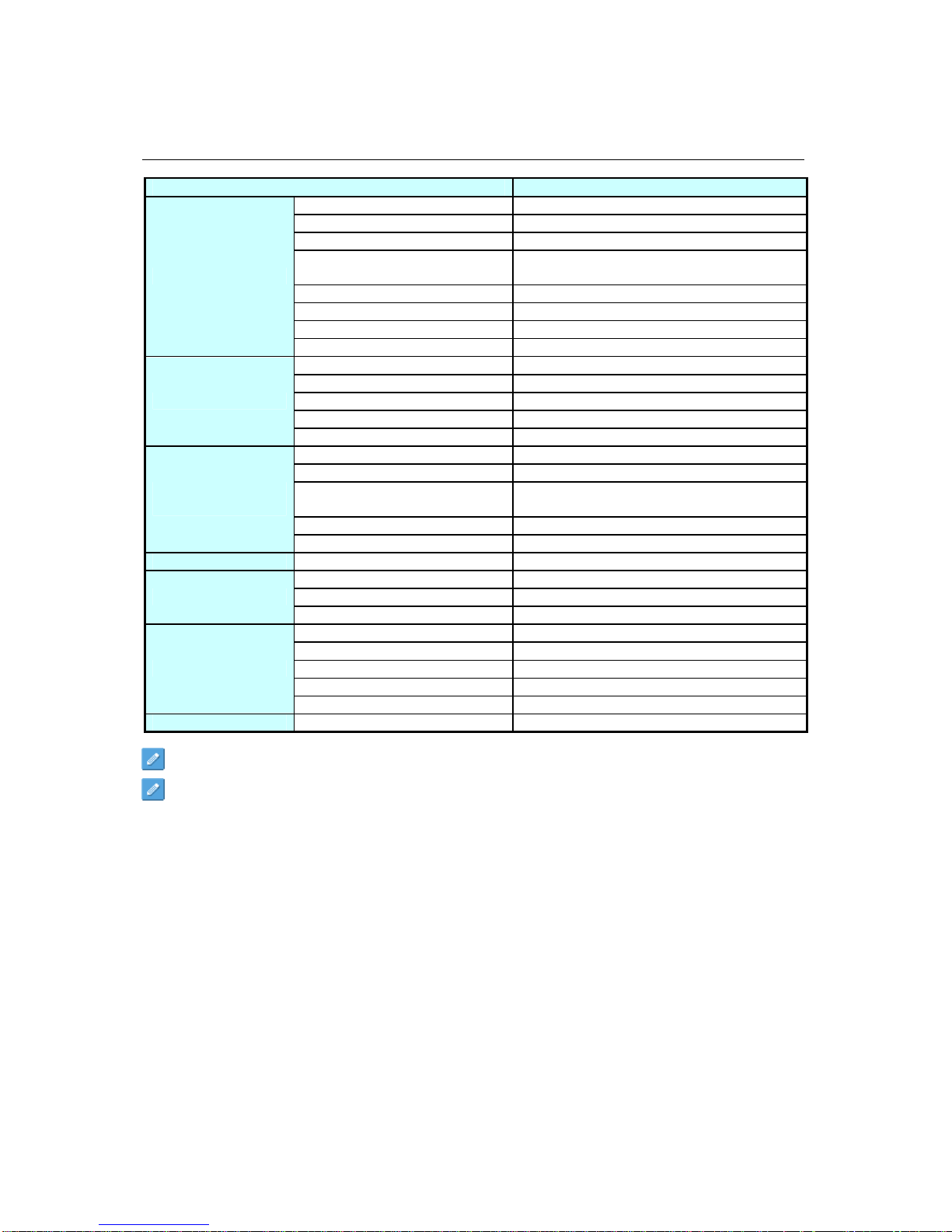
DS652LR5 User Manual 24
Specifications
MODEL DS652LR5
LCD Panel Size 64.53 inches
Native Resolution 1920 x 1080
Brightness 4000 cd/m² (Typ.)
Contrast Ratio
3,000:1 (Static)
10,000,000:1 (Dynamic)
Response Time 12 ms (Typ.)
Viewing Angle 178°/ 178°
Life Time 50,000 hrs (Typ.)
PANEL
Panel Surface AG Haze 1%, 3H
Power Supply Internal
Rated Voltage 100 ~ 240V, 50 / 60Hz
Power On Mode Typ. 510W / Max. 740W
Standby Mode < 1W
POWER
AC Out < 100W
Bezel Width (T/B/L/R) 18/18/11.9/11.9 mm
Cabinet Color Black
Monitor Dimension
(LxHxD, w/o Stand)
1457 x 844 x 102 mm
Monitor Weight (set / package) 52.5 kg / 56.5 kg
MECHANICAL
SPECS
VESA Mounting (Dimension) 8 Holes (400x400 mm / 400x600 mm)
USER INTERFACE
OSD Language English
Operation Temperature 0°C ~ 45°C
Storage Temperature -20°C ~ 60°C
ENVIRONMENT
Humidity 10%~80% RH Non-Condensing
DVI-D IN *1 / OUT *1 (support HDMI)
DP IN *1
RS-232 IN *1 / OUT *1
RJ-45 IN *1
I/O Ports
Audio IN *1 / OUT *1
Fuse
10A
Design and specifications are subject to change without notice.
The resolution of DVI-D out is 1920 x 1080 (1080p) only.
Page 26
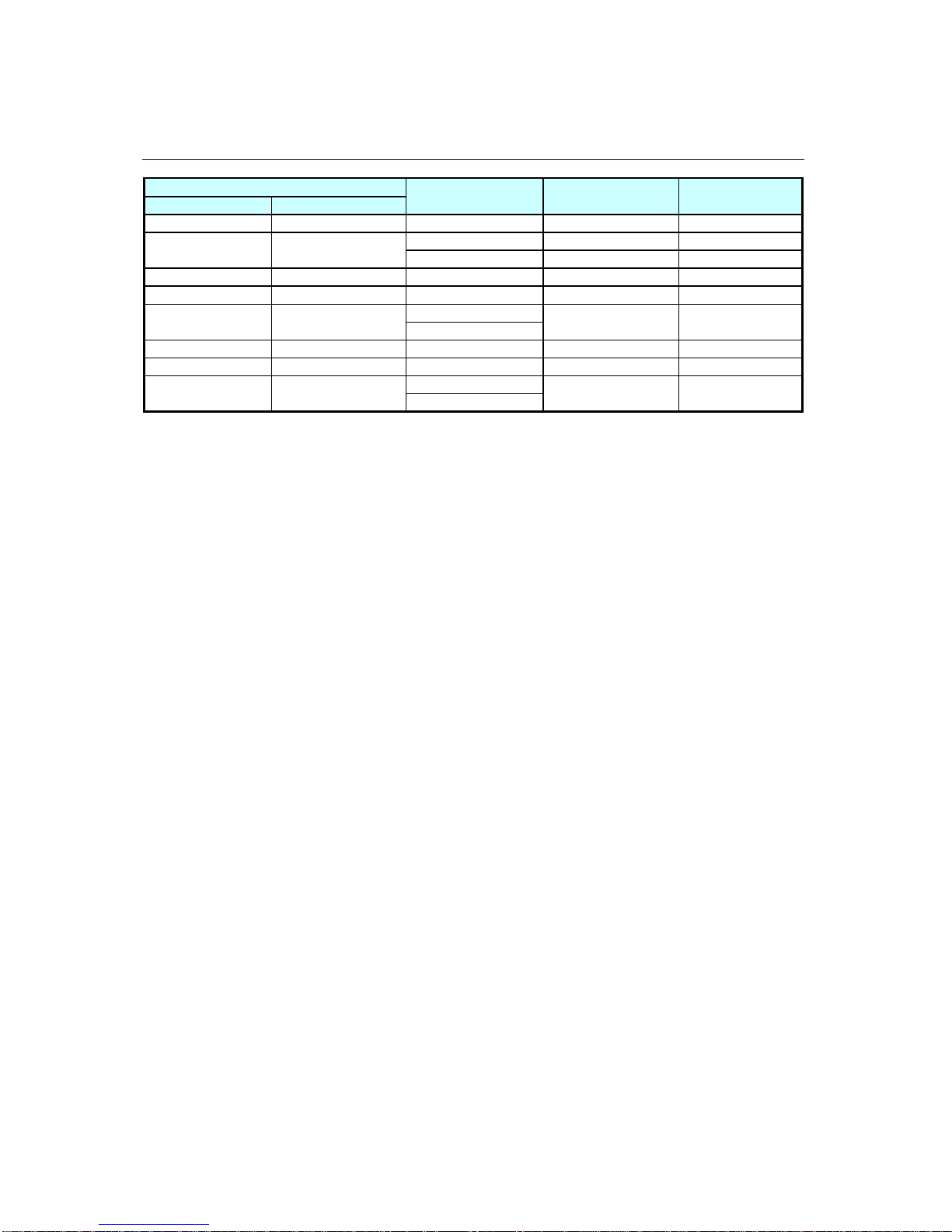
DS652LR5 User Manual 25
Input Mode
Active Resolution
H Pixels V Lines
Refresh Rate Pixel Rate Aspect Ratio
640 480 60 Hz 25.175 MHz 4:3
50 Hz 27 MHz 4:3
720 480
59.94 Hz 27 MHz 4:3
800 600 60 Hz 40 MHz 4:3
1024 768 60 Hz 65 MHz 4:3
50 Hz
1280 720
60 Hz
74.25 MHz 16:9
1280 768 60 Hz 79.5 MHz 5:3
1360 768 60 Hz 85.5 MHz 16:9
50 Hz
1920 1080
60 Hz
148.5 MHz 16:9
Page 27
DS652LR5 User Manual 26
Pin Assignments
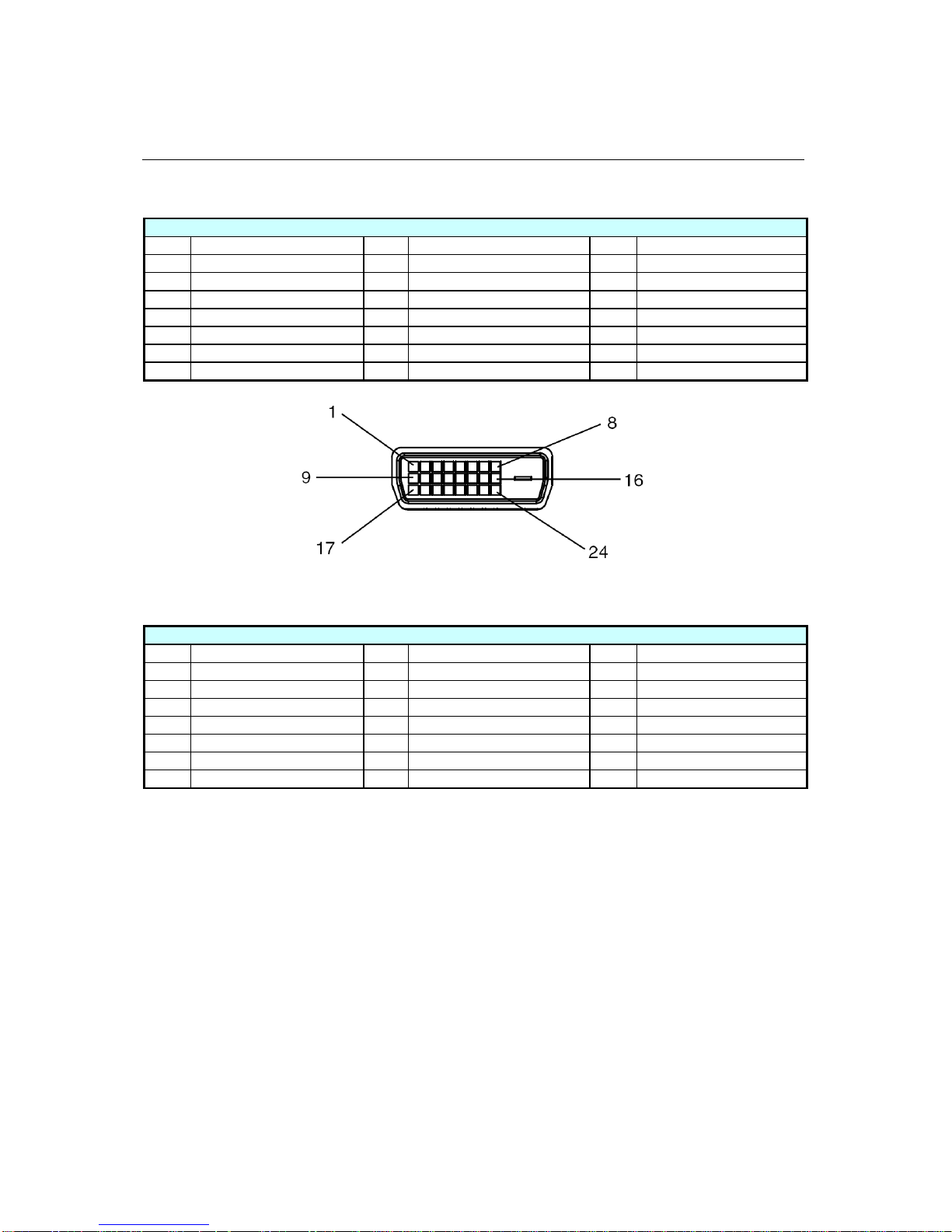
Digital RGB Output (DVI-D): DVI
PIN ASSIGNMENT OF DVI CONNECTOR
01 TX2- 09 TX1- 17 TX002 TX2+ 10 TX1+ 18 TX0+
03 Shield (TX2 / TX4) 11 Shield (TX1 / TX3) 19 Shield (TX0 / TX5)
04 NC 12 NC 20 NC
05 NC 13 NC 21 NC
06 DDC-Serial Clock 14 +5V power 22 Shield (TXC)
07 DDC-Serial Data 15 Ground 23 TXC+
08 NC 16 Hot plug detect 24 TXC-
Digital RGB Input (DVI-D): DVI
PIN ASSIGNMENT OF DVI CONNECTOR
01 RX2- 09 RX1- 17 RX002 RX2+ 10 RX1+ 18 RX0+
03 Shield (RX2 / RX4) 11 Shield (RX1 / RX3) 19 Shield (RX0 / RX5)
04 NC 12 NC 20 NC
05 NC 13 NC 21 NC
06 DDC-Serial Clock 14 +5V power 22 Shield (RXC)
07 DDC-Serial Data 15 Ground 23 RXC+
08 NC 16 Hot plug detect 24 RXC-
Page 28
DS652LR5 User Manual 27
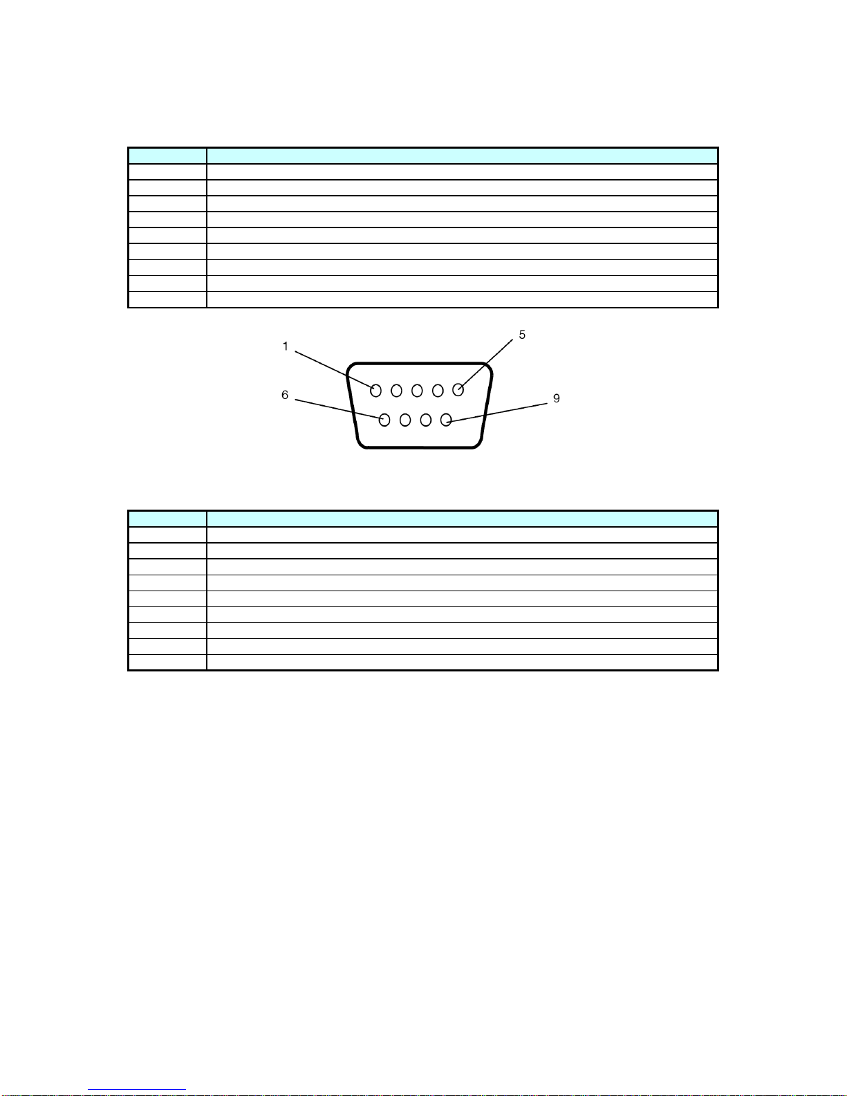
RS-232 Output
PIN No. NAME
01 Connected to 7&8
02 RXD
03 TXD
04 Connected to 6
05 GND
06 Connected to 4
07 Connected to 1&8
08 Connected to 1&7
09 NC
RS-232 Input
PIN No. NAME
01 Connected to 7&8
02 TXD
03 RXD
04 Connected to 6
05 GND
06 Connected to 4
07 Connected to 1&8
08 Connected to 1&7
09 NC
Page 29
DS652LR5 User Manual 28
Troubleshooting
ISSUE RECOMMENDED SOLUTION
No image is displayed.
Check whether the DVI in cable is completely plugged in.
Check whether the main switch is in the ON position, and the
power cord is completely plugged in.
Check whether the image source’s resolution is set to 1920 ×
1080 (1080p).
Check whether the DVI cable is damaged or bent excessively.
Nothing happens when
switching the main switch on.
Unplug the power cord from the socket and plug it in again
after a few seconds to reset the Signage.
Note: Unplugging the power cord will not change the settings.
Image is unstable. Check whether the DVI in cable is completely plugged in.
The remote control does not
work.
Check whether there are batteries in the remote control.
Check the batteries for freshness, polarity, etc.
Check whether the remote is in the operation range.
Bright light may interfere with the remote control. Please
avoid using the remote control near special fluorescent lights
or neon lights.
Auto on/off does not work or
does not function properly.
Check whether the TIMER setting in the menu is set to “OFF”.
Check whether the “Power On Time” and “Power Off Time”
settings are set correctly.
Cannot control the display
remotely via RS-232.
Check whether the RS-232 cable is connected properly.
If you are still having trouble with your DynaScan DS² Professional LCD, contact your dealer or
DynaScan directly for more assistance.
Page 30
DS652LR5 User Manual 29
Installation Notes
Handling
• Always use a team of people to handle the display.
• Extra care should be taken when handling narrow bezel LCDs. An impact with the edges could
cause the LCD panel to crack.
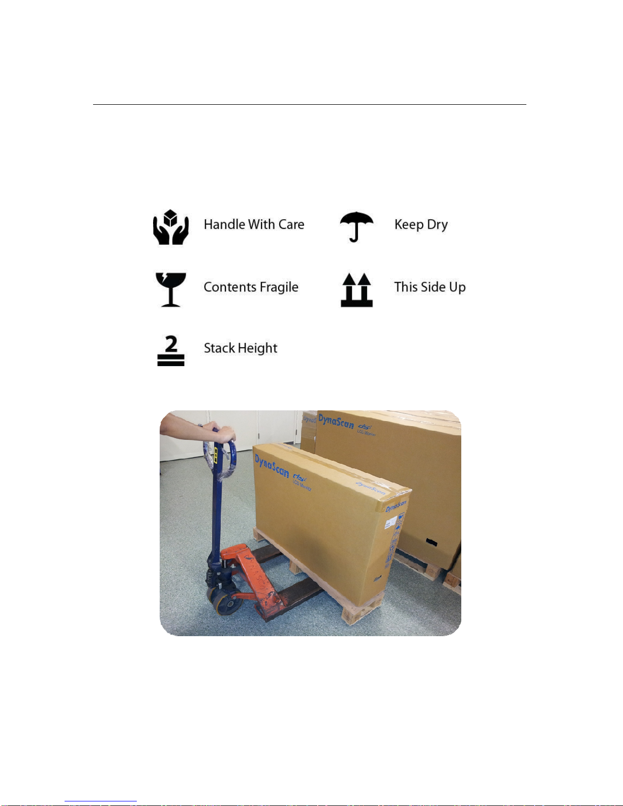
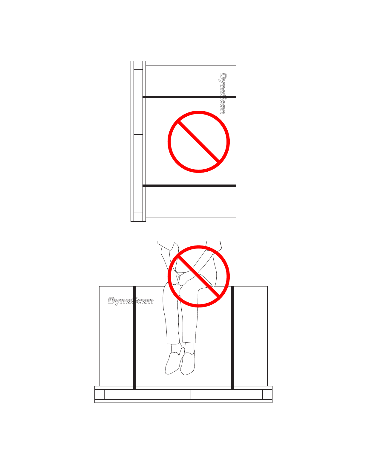
Adhere to the handling signs printed on the Box.
Use a pallet jack when moving the display
.
Page 31
DS652LR5 User Manual 30
Do not drop or lay the LCD box on its side.
Do not sit or lean on the box.
Page 32
DS652LR5 User Manual 31
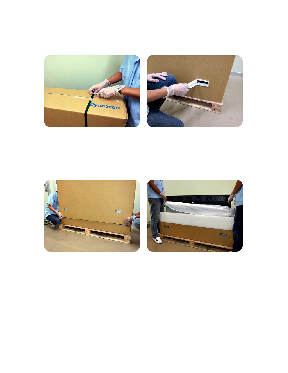
Unboxing the Display
1. Cut packing strap off the box.
2. Remove plastic clips by pulling tab.
3. Remove the top packaging by lifting up.
4. Remove the protective poly bag.
Page 33
DS652LR5 User Manual 32
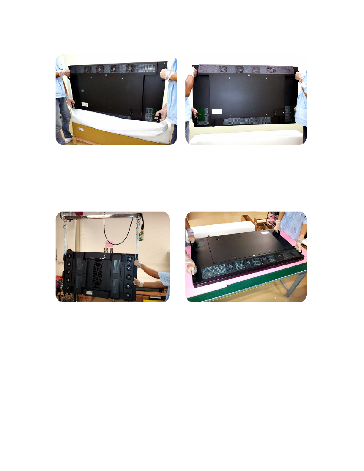
5. Lift up the set using the back handle and
remove bottom packing when lifting up the
display.
6. With two hands grabbing the set, move the
display.
7. For larger models, use a lifting tool when
unpacking or repackaging.
8. Lay the face of the display downward on a soft,
padded surface.
Page 34
DS652LR5 User Manual 33
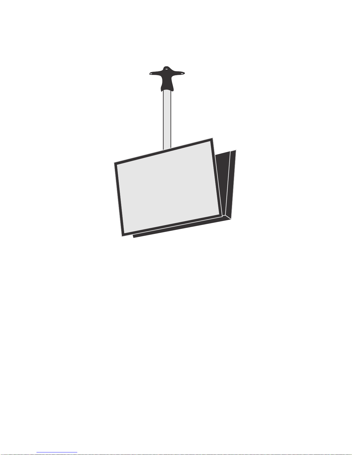
Hanging From a Ceiling
• Ensure that the ceiling is strong enough to support the LCD and it accessories. Also consider
the effects of earthquake, unexpected vibration, and other external forces when evaluating the
ceiling strength.
• The LCD should be secured to the building’s structural frame, such as a beam, and not to
materials such as light steel frame or interior decoration.
• Do not use wood screws or dry wall anchors for installation.
• Refer to the mount manufacturer’s instructions for proper installation.
When mounting on a wall or hanging from a ceiling
• Hanging the LCD from the ceiling or mounting it on the wall is the responsibility of the user. Not
all ceilings provide enough strength to support the LCD. The LCD may drop and cause serious
injury if it is hanging from the ceiling with insufficient support or is mounted on a slanted wall.
• Product warranty does not cover improper installation, modification, or damages caused by
natural disasters.
• DynaScan recommends hiring certified professionals to evaluate the installation site and
mounting operation.
• Do not to cover the vent and/or the heat sink in order to ensure proper heat dissipation.
Page 35
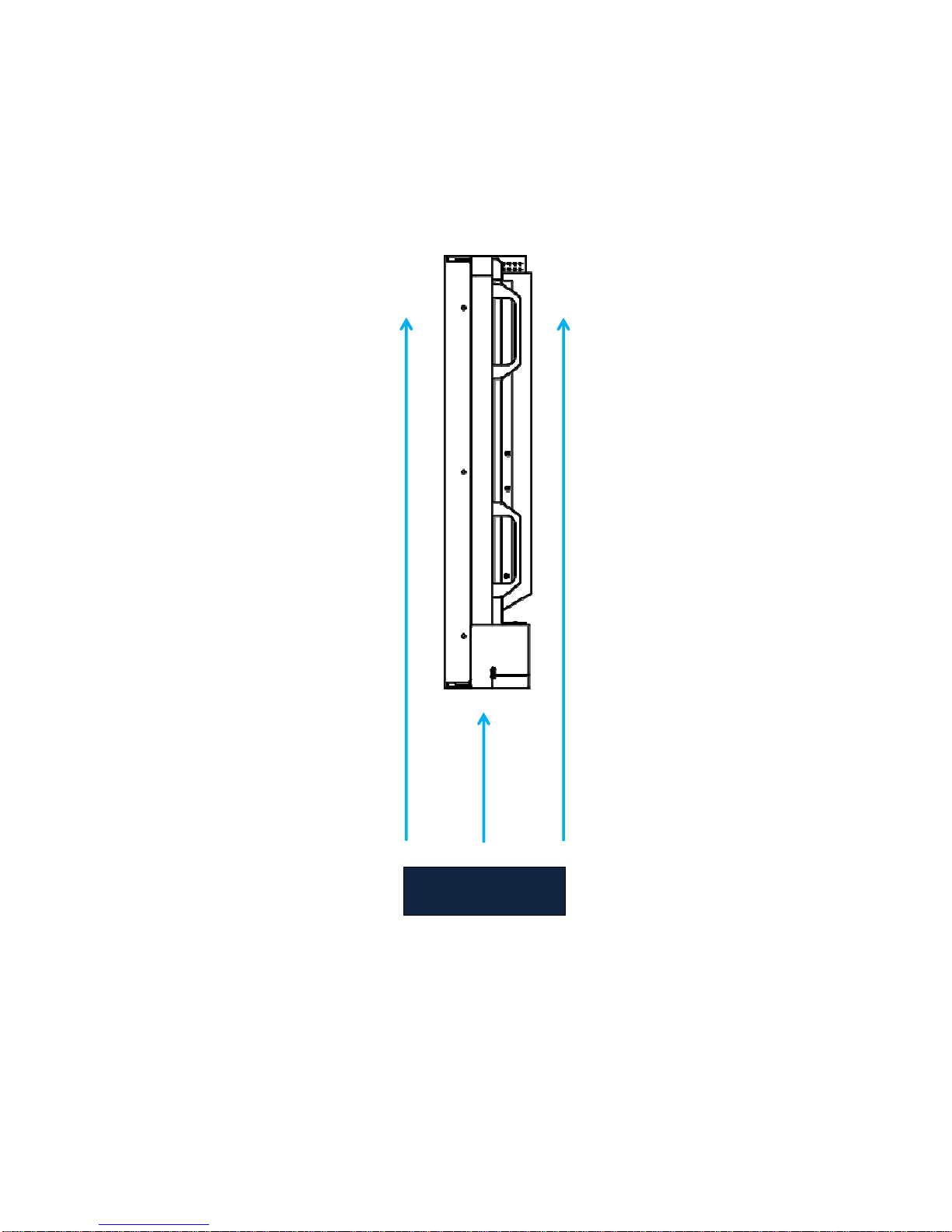
DS652LR5 User Manual 34
FAN
Operation Temperature
Operating temperature must be maintained between 0°C-40° C (32°F–104°F). To maintain the
proper operating temperature, you may consider using a cross flow fan beneath the display as shown
below.
Page 36
DS652LR5 User Manual 35
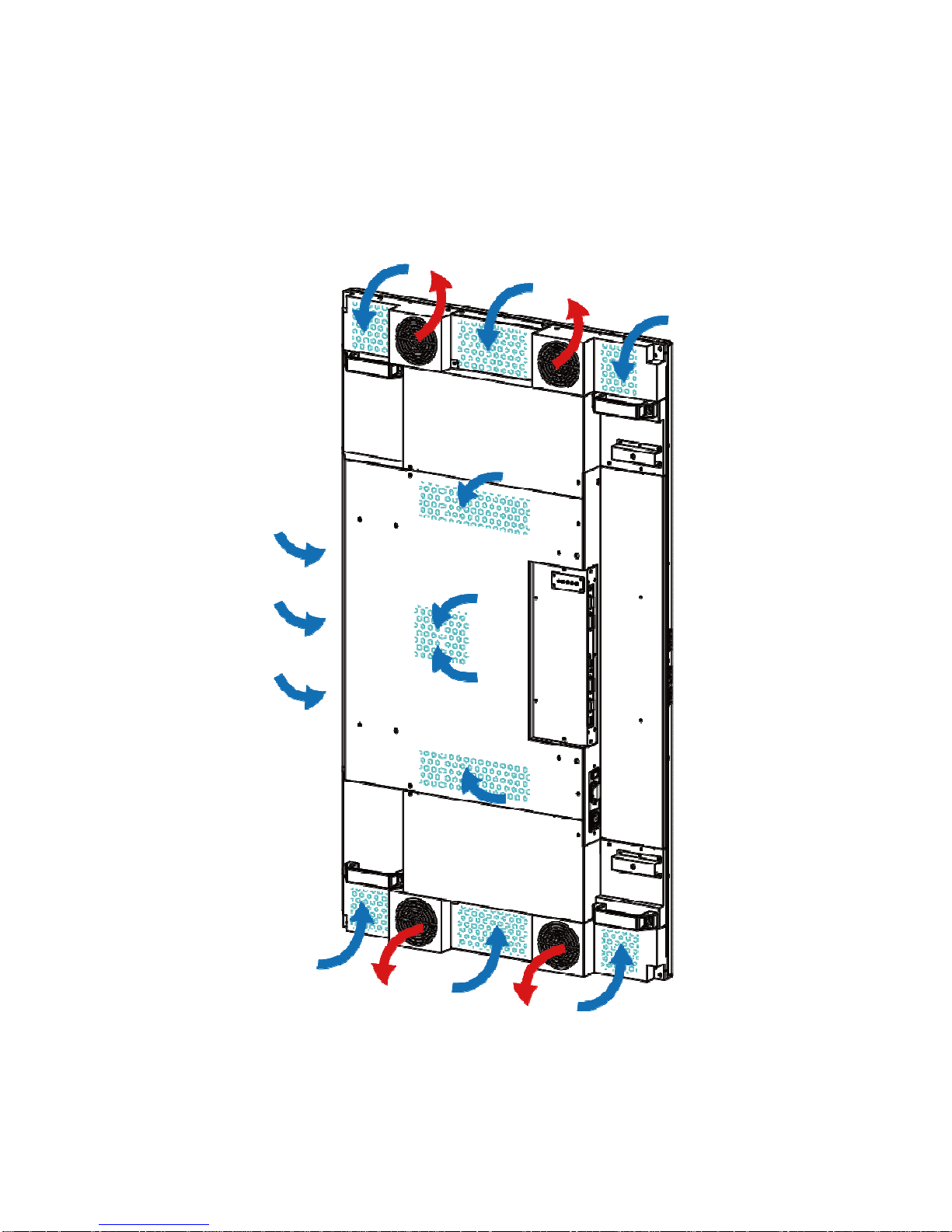
Ventilation (Fan-cooled models)
To maintain the proper operating temperature, cool air must be allowed to enter the display and hot air
must be allowed to exit the display. Obstructing fans and vents, or not providing cool air to the rear of
the display can cause the display to overheat. (See below example).
Page 37
DS652LR5 User Manual 36
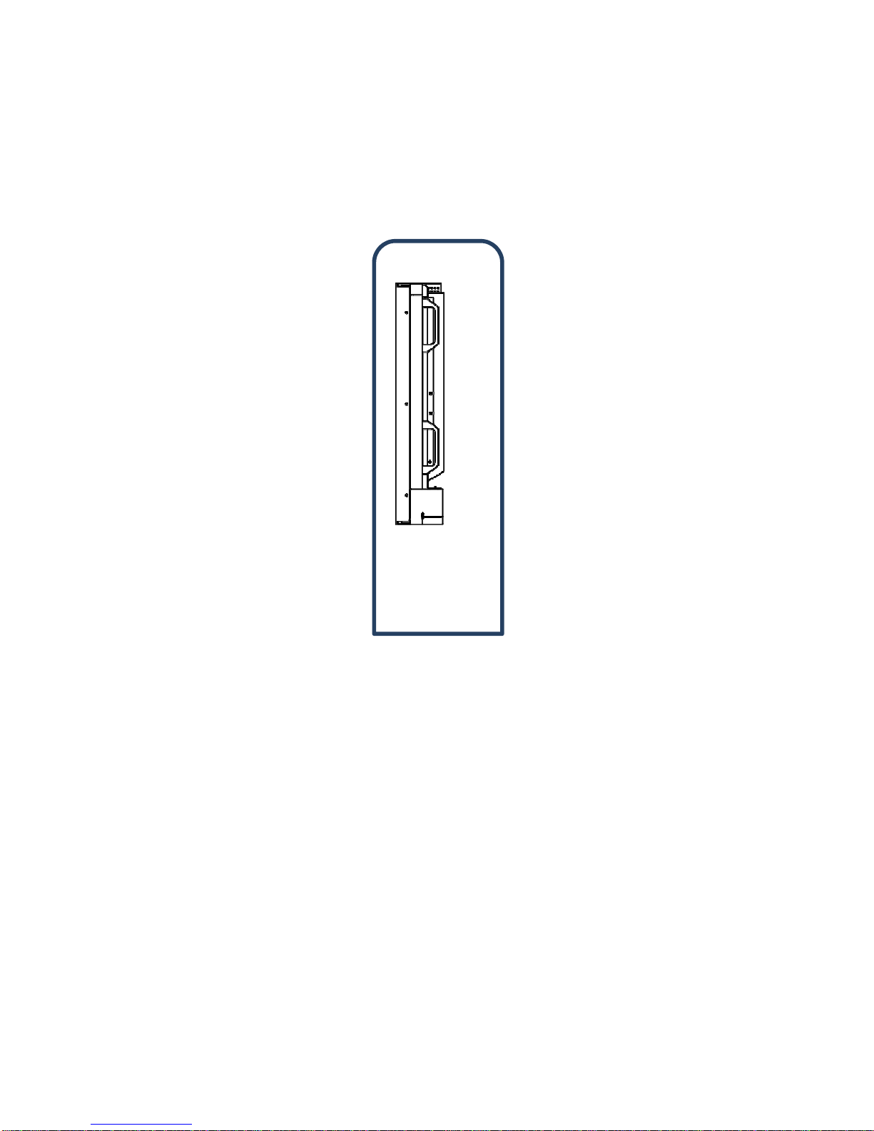
Enclosures
For outdoor applications, an external enclosure is required to protect the display. When designing the
enclosure, the temperature inside the enclosure must be maintained between 0°C-40°C (32° F–104°F).
Always consult your local enclosure builder or integrator for additional recommendations.
Enclosure
Using a Cooling & Heater Solution
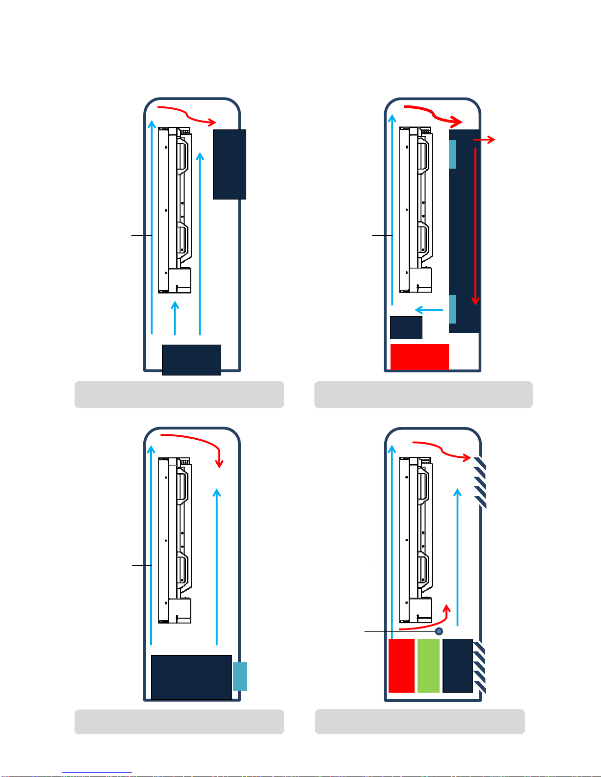
To maintain the proper operating temperature inside the enclosure, you may consider using a cooling
and heater solution such as an air conditioner, heat exchanger, or combined cooler and heater
depending on the external environment. (See below examples)
• You can also employ an air flow circulation system and air curtain* between the front panel and
the enclosure.
• An enclosure rated IP65 or better is recommended.
• Use an air filter to prevent dust. (At air inlet and outlet)
• For preventing from rust of lead frame in circuit board, operate the heater if relative humidity is too
high.
0°C - 40°C
Page 38
DS652LR5 User Manual 37
FAN
FAN
Example 1: Enclosure (Fans Only)
Air Curtain
HEAT EXCHANGER
Example 2: Enclosure (Heat exchanger)
Air Curtain
HEATER
FAN
AIR
CONDITIONER
Example 3: Enclosure (Air Conditioner)
Air Curtain
Example 4: Direct Air Cooling
Air Curtain
FAN
HEATER
FILTER
Humidity
Sensor
Page 39
DS652LR5 User Manual 38
FAN
In-Window Applications
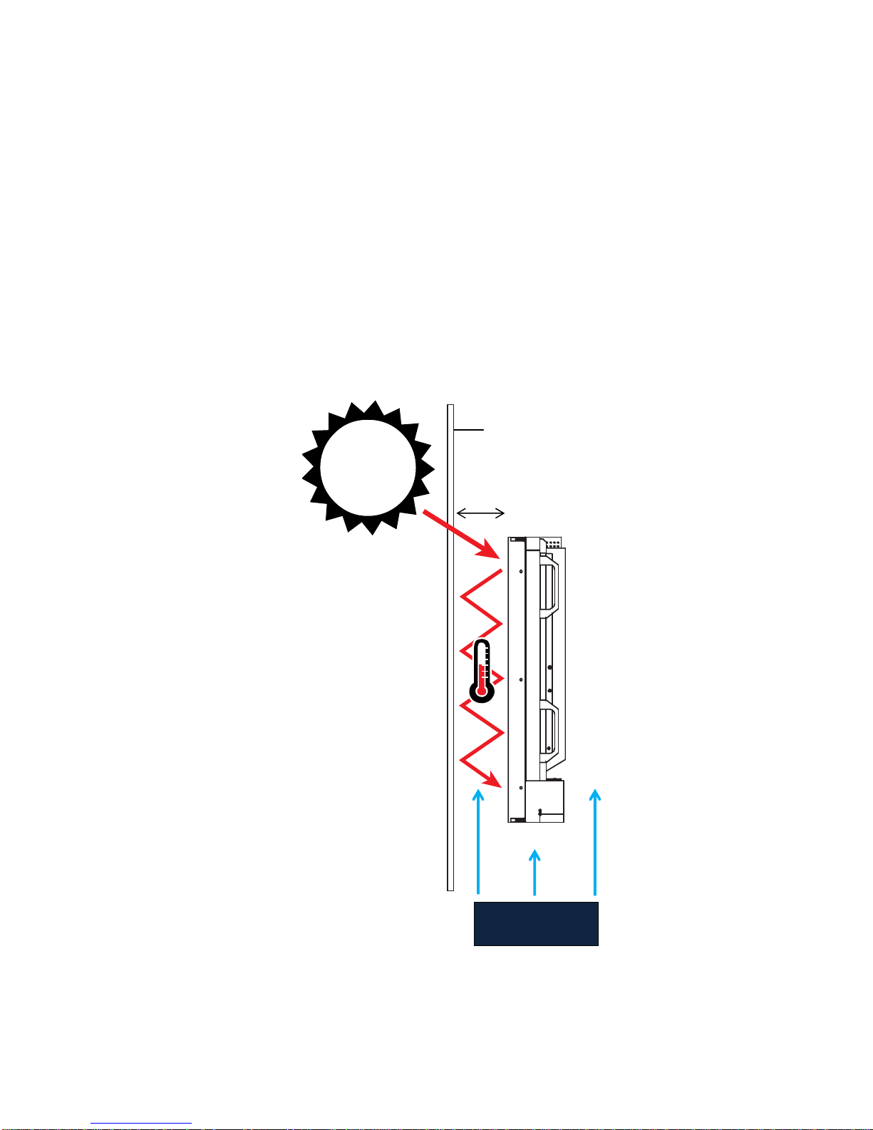
Extra cooling considerations must be made when placing a display in a window. Heat from sunlight
can become trapped between the window and the LCD panel surface, causing what is known as a
greenhouse effect. To maintain the proper operating temperature behind the window, you may
consider using a cooling solution such as a cross flow fan or air conditioner, (See below example)
• A gap of at least 10 cm (4”) is recommended between the window and the front of the LCD.
• A gap less than 10 cm, or installations in direct sunlight, will require the use of a cross flow fan.
• Both the area in front of the display and to the rear must be maintained between 0°C - 40°C
(32°F - 104°F).
• Electrical lighting such as spotlights can raise the ambient temperature in the area and should be
accounted for.
• The use of UV and/or IR films on the window may be used to help minimize heat entry. Consult
your local integrator for recommendations.
Window
10 cm
Page 40
DS652LR5 User Manual 39
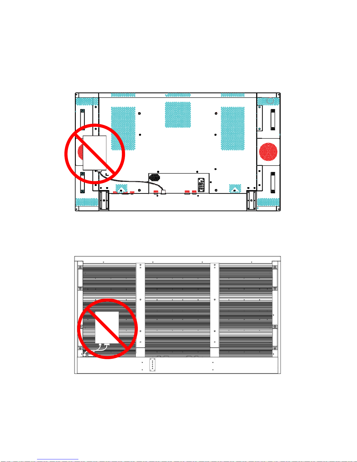
Media Player Location
Fan Cooled Models
If mounting a media player to the rear of the display, do not obstruct any of the fans or air vents to
allow for proper air ventilation. Failure to do so could damage the LCD and/or media player.
Fanless Models
If mounting a media player to the rear of the display, be sure to leave a gap between the heat sink and
the player device to allow for proper air ventilation. Failure to do so could damage the LCD and/or
media player.
Page 41
DS652LR5 User Manual 40
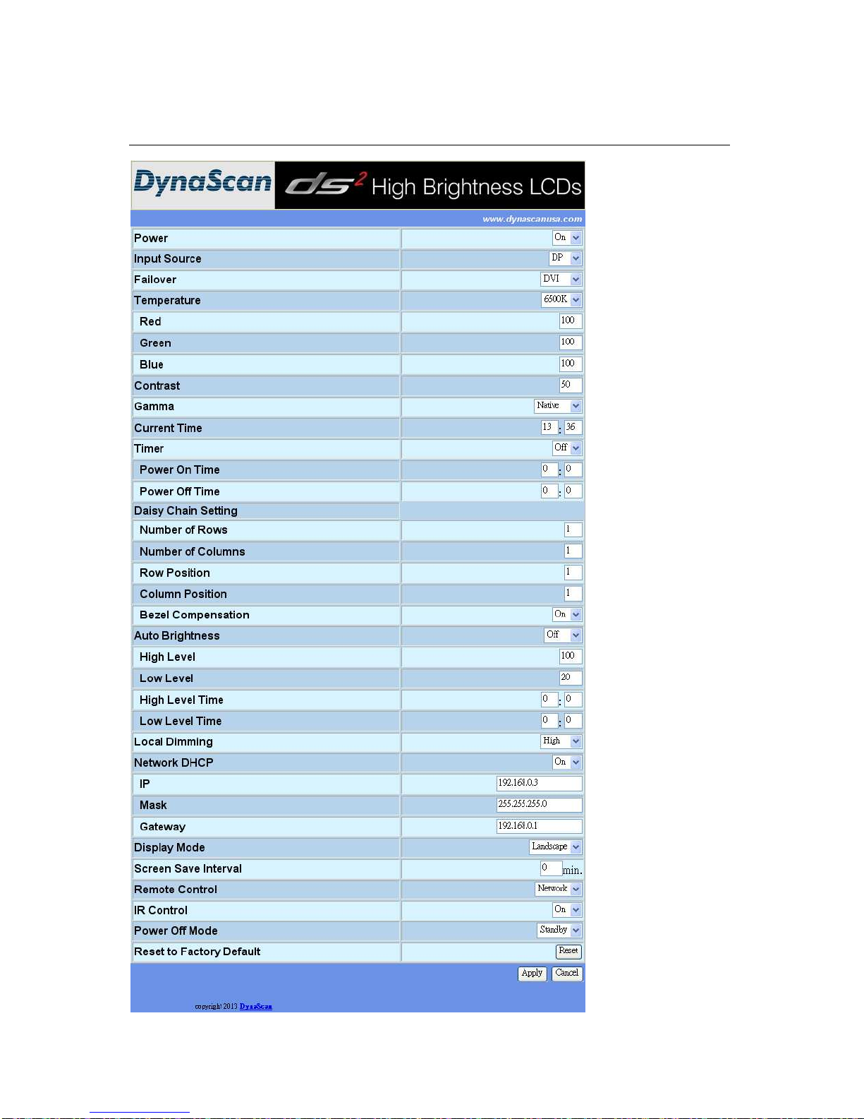
Network User Interface
Page 42
DS652LR5 User Manual 41
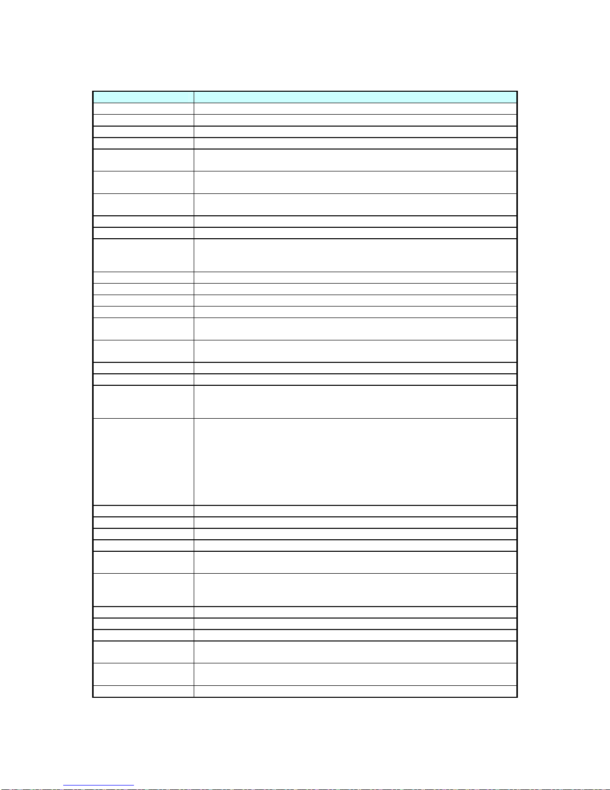
ITEM DESCRIPTION
Power Power On / Off.
Input Source Set the Main input to display. (DP(Display Port) or DVI)
Failover Set the Failover input to display. (DP(Display Port) or DVI)
Temperature Select the color temperature. (User, D93, D65 and D55).
Red
Adjust the red light level. Range 0 – 100.
Note: The feature is only supported on User mode.
Green
Adjust the green light level. Range 0 – 100.
Note: The feature is only supported on User mode.
Blue
Adjust the blue light level. Range 0 – 100.
Note: The feature is only supported on User mode.
Contrast Adjust the contrast level. Range 0 – 100.
Gamma Adjusts the Gamma value. (Native, 2.2, 2.4 and sgamma)
Current Time
Set the clock.
Note: The internal clock will continue to function when the power is turned
off.
Timer Turn on / off automatic power schedule function.
Power On Time Set turn-on time.
Power Off Time Set turn-off time.
Daisy Chain Setting
Number of Rows
Set number of rows in a video wall.
Note: The maximum number of rows in a daisy chain is 15.
Number of
Columns
Set number of columns in a video wall.
Note: The maximum number of columns in a daisy chain is 15.
Row Position Vertical position in a video wall.
Column Position Horizontal position in a video wall.
Bezel
Compensation
Choose to turn the frame compensation function on or off. When turned
on, the display will adjust the image to compensate the width of display
bezels in order to accurately display the image.
Auto Brightness
To turn On / Off the auto brightness adjustment.
Note: If the AUTO BRIGHTNESS is off, the screen brightness will remain at
HIGH LEVEL brightness value. If the AUTO BRIGHTNESS is on (Auto),
the display brightness adjusts according to the ambient light. When
ambient light is bright, the screen will adjust to the HIGH LEVEL brightness
value set; when ambient light is dark, the screen will adjust to the LOW
LEVEL brightness value set. When the Timer mode is set, the display will
automatically switch the brightness according to the time set.
High Level Adjusts the highest brightness level. Range 0 – 100.
Low Level Adjusts the lowest brightness level. Range 0 – 100.
High Level Time Set high level time.
Low Level Time Set low level time.
Local Dimming
Adjusts the contrast. High is the highest contrast. Off is the lowest
contrast.
Network DHCP
Choose to enable or disable the DHCP function. If enabled, the display will
assign the IP address, Subnet mask and Default gateway automatically. If
disabled, the following values will be entered manually.
IP Assign IP address.
Mask Assign Subnet mask.
Gateway Assign Default gateway.
Display Mode
Change the Menu orientation. The Menu can be displayed in either
LANDSCAPE or PORTRAIT mode.
Screen Save Interval
Turn on / off image burn-in protection.
Set image burn-in protection interval.
Remote Control Choose to use the remote control function RS232 or Network.
Page 43
DS652LR5 User Manual 42
ITEM DESCRIPTION
IR Control
Enable/disable the remote control for Menu.
Note: When disabled, the remote control function can be enabled again
from the control panel on the display or through the DynaScan “Display
Manager” application.
Power Off Mode
When in Power Off Mode, RS-232 controls do not function. Only [Main
Power Switch] on the display or [Power Button] on the remote control can
wake up the display.
Reset to Factory
Default
Restore all settings to default.
Note: It does not modify CURRENT TIME, POWER ON TIME and POWER
OFF TIME.
Apply Save the system for the changes to take effect.
Cancel Exit the system without saving any changes.
Page 44

Page 45

www.dynascanusa.com
Copyright © DynaScan Technology, Inc. All Rights Reserved.
 Loading...