

Dräger Medical PA-90 Service Manual

,
Q National Draeger, Inc. 1996

Notice
Proprietary Information
This service manual contains confidential
information in which National Draeger, Inc.
claims proprietary rights. The information is
disclosed in confidence, and may not be used,
reproduced or disclosed in whole or in part
except as authorized in writing by National
Draeger, Inc. This information is the property of
National Draeger, Inc., and is provided solely for
the use intended, and shall be returned upon
demand.
Repairs/Modifications
Repairs on this unit should be performed only by
National Draeger, inc., or its Authorized Service
Technicians. information about repairs can be
obtained from National Draeger, Inc., by
contacting the Technical Service Department at
P.O. Box 120, Pittsburgh, Pennsylvania 15230,
(412) 787-8383. National Draeger, Inc., will not
be responsible for injury to persons or damage
to property arising, directly or indirectly, from
unauthorized repairs or modifications to this unit.
Furthermore, any unauthorized repairs or
modifications voids any warranty extended by
National Draeger, Inc.
General
Section i
Rev.1
August 1996
1
NIOSH
Both the ProAir and the AirBoss are approved
by
NIOSH/MSHA
the code of Federal Regulations, Title 30,
Chapter
In addition, the AirBoss is certified by the Safety
Equipment Institute (red label) as meeting the
requirements of NFPA 1981 Standard for Open-
Circuit, Self-Contained Breathing Apparatus for
Fire Fighters, 1992 ed.
11,
(gold label) in accordance with
This service manual is provided for your
information only, updates will be sent out
periodically. All information subject to
change without notice.
i-i
PA-90 Series Service Manual

General
Section
Rev.
August 1996
i
1
Important Information
1. The ProAir and AirBoss are approved by
NIOSWMSHA and
standards. Any modifications, changes or
deviations from the documentation contained
herewith, will void the approval and may
cause a safety hazard. Contact National
Draeger for additional information concerning
approval requiremen
2. This unit is intended for those purposes
specified in the operating manual. Any
deviations are not authorized,
3. Only original National Draeger replacement
parts may be used in the maintenance and
servicing of this unit. Deviation from this shall
void any and all warranties and approvals.
4. All repairs to be accomplished by a National
Draeger certified Level II technician.
the
AirBoss meets NFPA
Is.
5. Authorized repair facilities and their personnel
shall assume all responsibility for timely and
reliable repair actions.
6. All governing specifications and regulations
must be observed in the repair, testing and
operation of this equipment.
IMPORTANT
For further information on any
supportive documentation contained in
this manual please contact National
Draeger, Inc. Technical Service
Department.
PA-90 Series Service Manuali -
ii

Table of Contents
General
Section i
Rev. 1
August 1996
Notice
Proprietary Information
Repairs/Modifications
important Information
..............................................................
.......................................
.........................................
........................................
I Theory of Operation
1
Backplate
1.1 Purpose
1.2 Construction
1.3 Features
2
Harness
2.1 Purpose
2.2 Construction
2.3 Features
3 Pressure Reducer
3.1 Purpose
3.2 Construction
3.3 Features
Cc
3.4 Technical Data
4 Chest Mounted Whistle Warning Unit.......... 4
4.1 Purpose
4.2 Construction ........................................
4.3 Technical Data ....................................
5 Chest Gauge
5.1 Purpose
5.2 Construction
5.3 Features
6
Lung Demand Regulator ............................. 7
6.1 Purpose
6.2 Features
6.3 Technical Data
7 Panorama Nova Mask
7.1 Purpose
7.2 Construction
7.3 Features
7.4 Technical Data ....................................
8
Cylinder and Valve Assembly
8.1 Purpose
8.2 Features
8.3 Technical Data
.....................................................
...............................................
........................................
..............................................
.......................................................
...............................................
........................................
..............................................
.......................................
...............................................
........................................ 3
.............................................. 3
.................................... 3
...............................................
...............................................
...............................................
........................................
..............................................
...............................................
..............................................
.
................................... 7
.................................
............................................... 9
........................................ 9
..............................................
....................
.............................................
...........................................
..................................
.
i
i
i
ii
2
2
2
2
2
2
2
2
3
3
4
4
4
5
5
5
5
7
7
9
9u
9
10
10
10
10
II Disassembly/Assembly
1
Pneumatic Arrangement Maintenance
1 .lReplacing Pressure Gauge
1.2 Disassembly/Assembly of Whistle..
Warning Unit
1.3 Replacing High Pressure Hose
1.4 Replacing Medium Pressure Hose..
2
Demand Regulator Maintenance
2.1 Replacing Diaphragm
2.2 Replacing Balanced Piston Unit
2.3 Replacing/Refitting PP Arm Return
Spring ..................................................
2.4 Replacing Balanced Piston Springs
2.5 Replacing Demand Regulator Hose . . 11
3
Panorama Nova Mask..
3.1
Changing the Mask Lens
3.2 Changing the Exhalation Valve
3.3 Changing the Speech Diaphragm
3.4 Changing the Connector....................
4 Backplate/Pneumatic Lines
5 Cylinder Valve
5.1
High Pressure Gauge
5.2 Burst Disc
5.3 Handwheel
5.4 Valve Removal
’
........................................
...........................................
..........................................
........................................
........ 2
.................
........... 4
................. 6
..........................
..........
.............................
...................
.........
..... 13
.......................
........................
..................................
2
.......
3
.... 5
6
7
8
.... 9
12
12
13
14
15
16
16
16
17
17
i
-
iii
PA-90 Series Service Manual
General
Section i
Rev. 1
August 1996
III
Testinflroubleshooting
1 Testing/Troubleshooting
Test Kit Operations ,....,.,#.....................
1
.l
1.1.1
1 .1.2 High Pressure Cylinder Test . . . . 2
1 .1.3 High Pressure Leak Test ,........ 2
1 -1.4
1 .1.5 Whistle Activation
1 .1.6 LDV Positive Pressure Leak
1 .1.7 LDV Static Positive Pressure . . . . .
1 .1.8 LDV Negative Pressure Leak . . . .
1 .1.9
1.1.10 Mask Leak Test . . . . . . .
1 .l .l 1
LeakTest
Medium Pressure Test . . . . . . . . . . . . 2
Test
. . . . . . . . . . . . . . . . . . .
Test
. . . . . . . . . . . . . . . . .
Test
LDV Bypass Function . . . . . . . . . . . . . . 3
Exhalation Valve Opening Test 4
..,...,.....*.........,.*.....
. . . . . . . .
..**..*...........I*..*..
. . . . . . . . . . . . . . . . . . . . 3
..I................... 3
..,...
. . . . . . . . . . . . . . . . . .
. . . . . . ..*...............................*
..-..........
IV Maintenance Schedules/
Equipment
1 .lMaintenance Procedures
1.1.1
Facepiece
1.1.2 Lung Demand Valve (LDV)
1.1.3 Pressure Reducer and Hose
Assembly .................................
1.1.4 After Each Use ,.,.:. .................. 5
1.1.5 Functional Test ........................
1.2
Maintenance Schedule ........................ 7
1.3 Maintenance Equipment......................
1.3.1
Maintenance Support
Equipment ............................... 8
1.3.2 Torque Specifications ............
1.3.3 Lubricants and Adhesives..
................................
.................... 2
2
2
4
......
10
.... 11
V Service Reporting
2
1
Service Reporting . . . . . . . . . . . . . . . . . . . . . . . . . . . . . . . . . . . . . . . .
2
SCBA Service
3 Terms of Payment
4 Return Goods Policy
5
Emergency and Rush Orders . . . . . . . . . . . . . . . . . . . . . .
6 Return Goods Authorization
7 National Draeger’s Product Service
In The U.S.A.. . . . . . . . . . . . . . . . . . . . . . . . . . . . . . . .
Log . . . . . . . . . . . . . . . . . . . . . . . . . . . . . . . . . . . . . . .
..,....................................
. . . . . . . . . . . . . . . . . . . . . . . . . . . . . . . . . . .
. . . . . . . . . . . . . . . . . . . . . . . .
..m..*......... 6
2
3
4
4
4
5
VI Service Instruction History
3
3
2
3
5
5
8
PA-90 Series Service Manual
i
- iv

,
,
-1
I

Theory of Operation
Section I
Rev. 1
August 1996
1
Bat
kplate
1 .I Purpose
The PA-90 Series backplate is ergonomically
designed to provide maximum comfort and
minimum stress on the back!
1.2 Construction
The PA-90 Series backplate is made of compos-
ite materials for maximum strength and mini-
mum weight. The ProAir backplate may be blue
or gray and is composed of nylon and fiberglass
filaments. The AirBoss is black and is composed
of nylon and carbon filaments.
1.3 Features
The PA-90 Series backplates have a shock
absorbing rubber bumper on the base. The
backplate also has convenient carrying handles
on both sides and is highly chemically resistant.
The AirBoss backplate is anti-static.
2
Harness
2.1 Purpose
The harness is designed to be easily and quickly
donned and adjusted to fit each individual.
2.2 Construction
The ProAir harness is composed of polyester
webbing. The AirBoss harness webbing is
composed of a Kevlar/Nomex PBI composite
material. This material has unparalleled
strength, fire retardation and wear resistance. It
can be easily removed and washed if necessary
for decontamination. Washing will not affect the
above mentioned characteristics.
2.3 Features
The ProAir is fully adjustable for both the
shoulder straps and waist strap. It can be easily
removed from the backplate for cleaning if
necessary. The ProAir has a highly fire retardant
polymeric buckle.
J
*
\
PA-90 Series Service Manual* -
The AirBoss is fully adjustable for both the
shoulder straps and waist strap. The AirBoss
harness has a pull-forward waist belt adjustment
and a waist pad to transfer weight away from the
shoulders for additional support and comfort. It
also comes equipped with shoulder pads. A lung
demand regulator (LDR) holder is provided on
the waist belt for convenient stowage when not
in use. The entire pneumatic system can be
re,adily
removed for decontamination. The waist
belt buckle is either a push-button, stainless
steel, automotive-type or highly fire retardant
polymeric buckle.
2

Theory of Operation
Section I
Rev.
1
August 1998
3
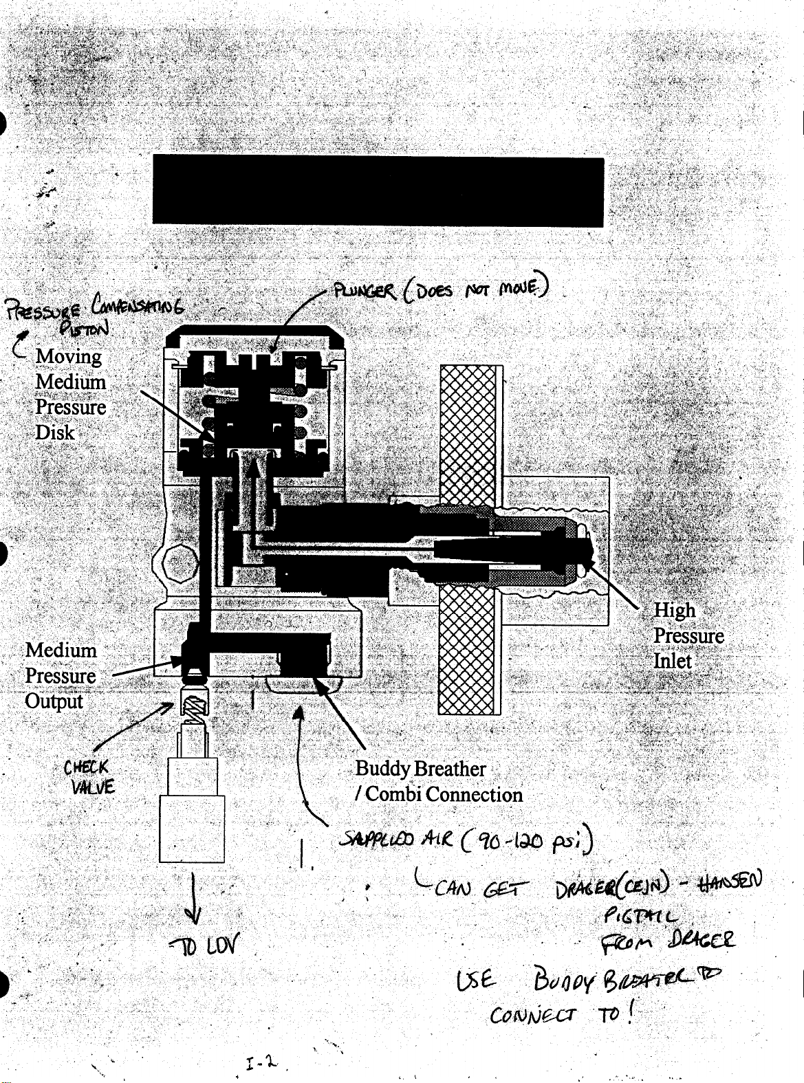
Pressure Reducer
3.1 Purpose
The purpose is to reduce the cylinder pressure
from a maximum 4500 psi down to a medium
pressure between 87-130 psi while delivering
high flow when needed.
3.2 Construction
The pressure reducer is a balanced piston type
which provides a controlled medium pressure
regardless of cylinder pressure. It contains a
pressure relief valve to prevent over pressurization of the medium pressure chamber. It is
connected to the cylinder by CGA fittings.
3.3 Features
High pressure air enters the reducer via a
cylinder connector which is fitted with a sintered
bronze filter.
3.4 Technical Data
First Stage Reducer
Outlet to High Pressure Manifold
~25
Ipm @ 2900 psi
Medium Pressure
Relief Valve
87-130 psi
180-230 psi
The high pressure air flows through the piston
into the reducer body which forms a medium
pressure chamber. As the air flows into the
medium pressure chamber, it forces the piston
to close against the plunger,the medium
pressure should read between 87-130 psi.
On inhalation, medium pressure air flows from
the medium pressure chamber. As the pressure
within the chamber is now reduced, the spring.
reopens the piston allowing the cycle to be
repeated.
An optional pigtail with a female Cejn connector
is available. When provided, it permits both
buddy breathing or the connection of an external
breathing air line. The pigtail is supported on the
left side of the waist belt.
*
I- 3
PA-90 Series Service Manual
‘*
.
I-1.
I.
L
I
. .
.,
:;.,_
.._
Theory of Operation
Section I
Rev. 1
August 1996
4
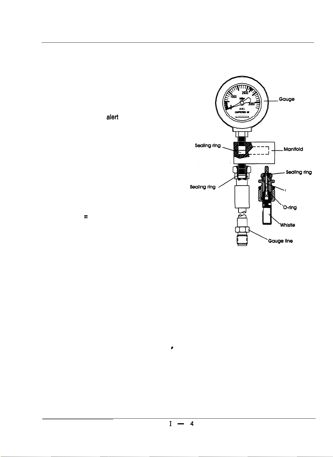
Chest Mounted Whistle
Warning Unit
4.1 Purpose
The purpose is to audibly alert the user when
the air supply reaches approximately 25% of full
cylinder capacity.
4.2 Construction
The high pressure whistle warning unit is fitted
to a manifold block. The manifold block is fitted
to the gauge line. The whistle is located on the
left shoulder harness, close to the ear, making it
easier to hear the whistle.
4.3 Technical Data
Mean Flow Rate = 2 lpm
Critical orifice
Figure 1
PA-90 Series Service Manual
1 - 4

Theory of Operation
Section I
Rev.1
August 1996
5
Chest Gauge
5.1 Purpose
The chest gauge allows the wearer to monitor
the cylinder pressure at all times.
5.2 Construction
The chest gauge is a Bourdon type with a
heavy-duty stainless steel case.
5.3 Features
The chest gauge has a large dial face for easy
readability and luminous markings for visibility in
low light conditions. The gauge is attached to
the chest manifold.
I- 5
PA-90 Series Service Manyal
Theory of Operation
Section I
Rev. 1
August 1996
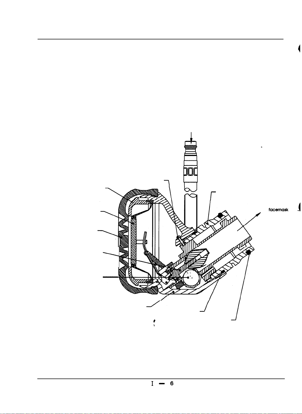
Lung Demand Regulator
Retaining cap
_
Air
Retaining screw
7
Plug-in connection
l-
Medium
pressure banjo sealing rings
Silicon diaphragm
LDV cover
Balanced piston assembly
-1
-
LDV housing
To
Sealing ring
*
\
J
Sealing ring
J
Figure 2
PA-90 Series Service Manual1 -
6
Theory of Operation
Section I
Rev. 2
August 1996
6
Lung Demand Regulator
6.1 Purpose
The lung demand regulator has
functions:
1. To provide the air demanded by the respiratory system
2. To always provide a positive pressure to the
mask interior
two main
6.2 Features
w
The lung demand regulator (LDR) has automatic
first breath activation to positive pressure. The
bypass control on the right side of the housing
can be depressed and locked in position to
provide a constant flow of air. The donning lever
is also on the right side. The lung demand
incorporates a simple, effective “push-in”
connection to the face mask port, and is sealed
by a silicone o-ring.
6.3 Technical Data
Input pressure
output flow
Bypass flow range
Static Positive Pressure
Positive Pressure
Activation
87-130 psi
500 Ipm
80-130Ipm
1 - 3.75 mbar
@-5mbar
5
*
I- 7
PA-90 Series Service Manual
Theory of Operation
Section I
Rev. 1
August 1996
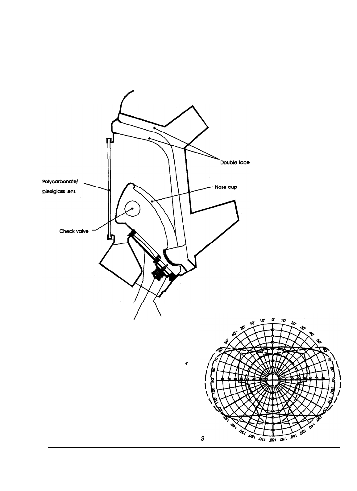
Panorama Nova Mask
f
seal mask body
Speech diaphragm O-ring
Bridge and spring assembly
’
/\
Exhalation valve
Diagram Field of Vision
PA-90 Series Service Manual
Figure
I- 6

Theory of Operation
Section I
Rev. 1
August 1996
7
Panorama Nova Mask
7.1 Purpose
The Panorama Nova Mask is used with the
quick disconnecting LDR to provide compressed
air to the user’s respiratory system.
7.2 Construction
The Panorama Nova Mask is available in three
materials:
1,
EPDM (Ethylene Propylene Dimonomer)
2. Silicone
3. Neoprene
Mask construction is the same for all materials.
7.3 Features
b
The Panorama Nova Mask uses a lens design
that features 90% peripheral vision availability.
The mask utilizes a five-point harness for proper
sealing. Four of the harness points go on the
sides of the head and one harness goes over
the center of the head. A neck strap is also
provided for transporting the mask.
I
National Draeger uses a speech diaphragm
made from stainless steel (stamped with the
letter N). This material provides excellent sound
transmittance and is less susceptible to chemi-
cal deterioration.
The mask is constructed with a double face seal
to ensure a good fit over a wide range of facial
features. One size fits all.
7.4 Technical Data
Material(s) EPDM, Neoprene, Silicone
Exhalation Valve
2
Opening
View Area 90 % of peripheral vision
Lens material(s)
Polycarbonate, Plexiglass
4.5 mbar
The input connecting section is manufactured so
that the incoming air is flushed past the lens and
into the respiratory system. This system helps
prevent fogging of the lens.
The mask comes standard with a nosecup that
also helps reduce fogging, takes up dead-air
space and channels the voice into the speech
diaphragm. Nosecup usage is required by
NIOSH when temperatures are below 32 *F.
e
’
I- 9
PA-90 Series Service Manual
Theory of Operation
Section
Rev. 1
August 1996
8
I
Cylinder and Valve
Assembly
8.1 Purpose
The PA-90 Series cylinders are used as lightweight storage containers for the breathing air.
To ensure the wearer’s safety and that the
cylinder remains free of contaminants, Grade D
or better gaseous air, as specified by the
Compressed Gas Association Commodity
Specification for Air, G-7.1, ANSI 286.1 must be
used in the cylinders.
8.2 Features
The cylinders use aluminum valves with CGA
connectors. The valves have safety discs (burst
discs) installed that are designed to prevent
over-pressurization. These discs are designed
to rupture at approximately
pressure. The valves utilize a straight thread
design that permits the use of an o-ring seal
when attaching to a reducer. This seal system
ensures that the connection between the
cylinder and the reducer need only be
tightened.
513
the rated service
hand-
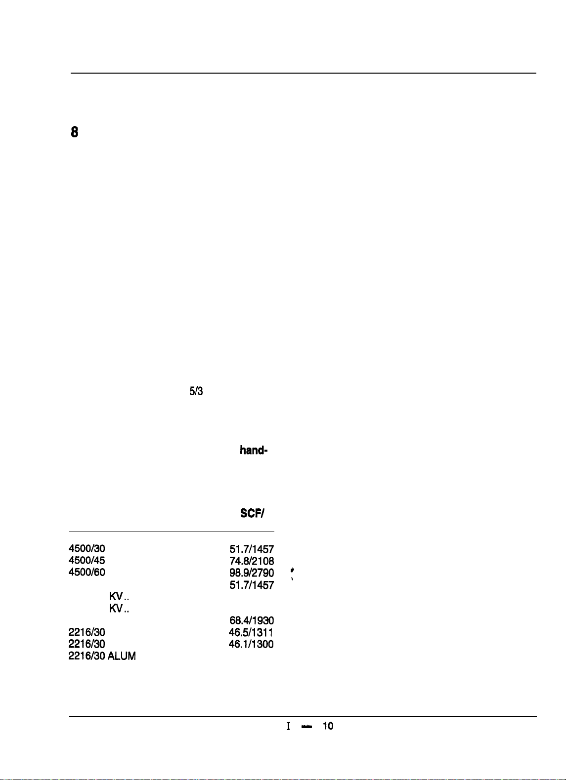
8.3 Technical Data
Pressure/ Weight,
Minutes Lbs w/Air
4500/30
4500/45
4500/60
4500130 Kv..:...............
4500145
4500160 KV..
2800145 FG ................ 19.2 ...........
2216/30 FG HW
2216/30
2216130ALUM
FG ................ 13.2 ...........
FG ................ 20.2 ...........
FG
................
W..
............... 17.0
...............
FG FW.......... 13.2.. .........
........... 21.3 ........... 45.911295
25.0
...........
12.1
...........
...........
21.7 ........... 98.912790
.........
16.1
...........
SCW
Liter
51.7/1457
74.8/2108
98.9/2790
51.7/1457
74.812108
68.4/1930
46.5/1311
46.1/1300
PA-90 Series Service Manual
1 - 10

c
II -1
Disassembly/Assembly
Section II
Rev. 1
August 1996
1
Pneumatic Arrangement
Maintenance
Tools required
14 mm AF open ended spanner
20 mm AF open ended spanner or adjustable
spanner
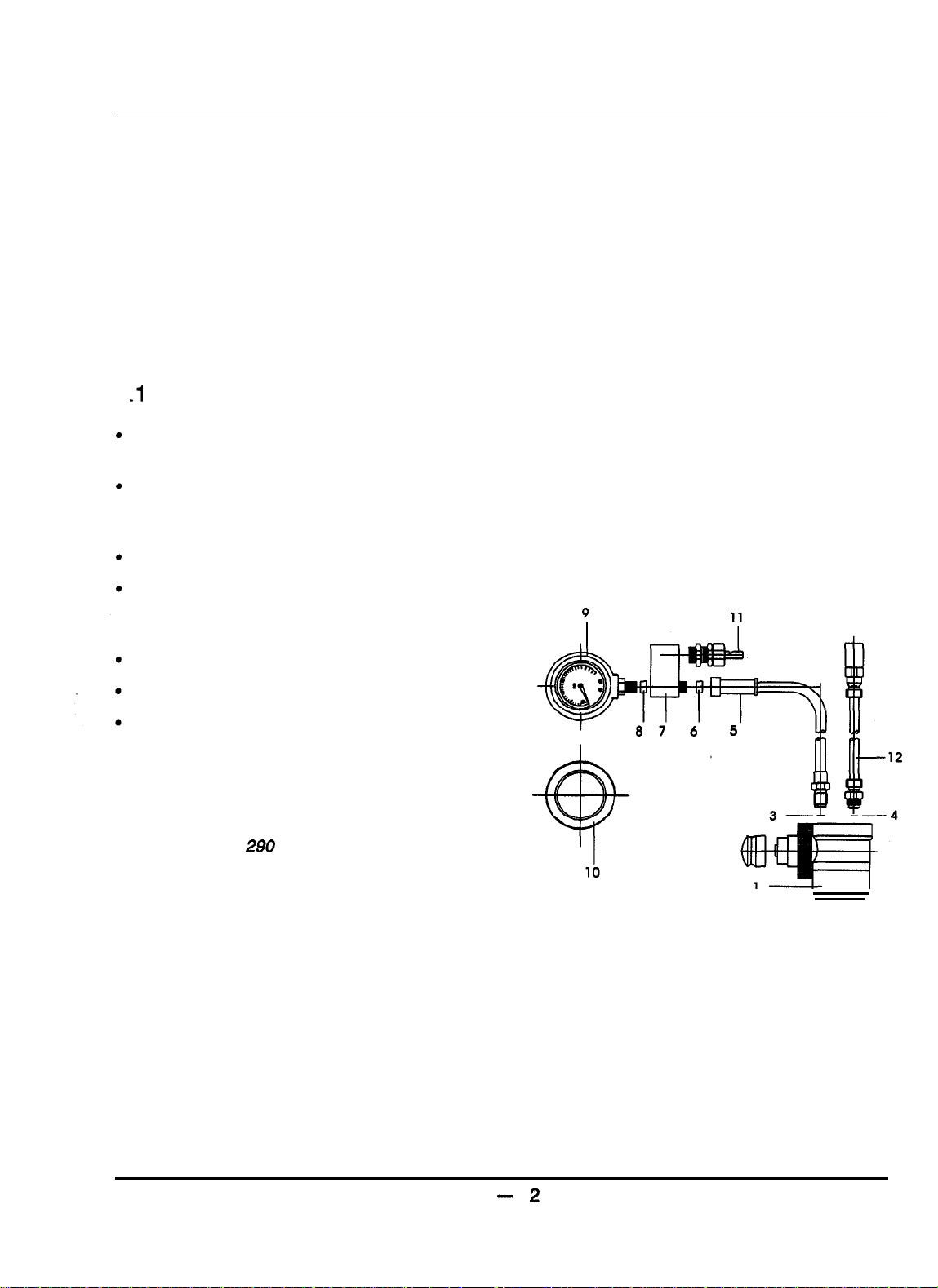
1
.I
Replacing Pressure Gauge
Hold manifold block (7) using either adjustable
or 20 mm AF open ended spanner.
Use 14 mm AF open ended spanner or
adjustable to unscrew gauge (9) from manifold
block.
Remove gauge cover (10) (Figure 1).
Remove sealing washer (8) from bore of
manifold block and inspect bore thread for
damage.
Insert new sealing washer into manifold block.
Refit gauge cover.
Screw new gauge into manifold using
spanners. Ensure correct orientation as
shown in Figure 1.
NOTE
Hold assembly with gauge vertical and
apply Loctite 290 sparingly around
gauge thread, following initial thread
engagement,
Figure 1
PA-90‘ Series Service Manual
II
- 2
 Loading...