


Dräger Medical Caleo Service Manual
Technical Documentation
Caleo®
Neonatal incubator
Revision 5.1
6150.000
9036116
Because you care


Contents
General
1 Symbols and Definitions 3
2 Notes 3
Function Description
1 Function Description 7
1.1 Canopy ................................................................................................................................... 8
1.2 Sensor unit ............................................................................................................................. 9
1.2.1 WT2 Sensor PCB ..................................................................................................... 9
1.2.2 Integrated O2 Monitor PCB .................................................................................... 14
1.2.3 Alarm PCB with alarm light ..................................................................................... 15
1.3 Display housing .................................................................................................................... 16
1.3.1 Housing .................................................................................................................. 16
1.3.2 Membrane keypad .................................................................................................. 17
1.3.3 EL display (electroluminescent display) ................................................................. 17
1.3.4 WT2 Controller PCB ............................................................................................... 18
1.3.5 Loudspeaker ........................................................................................................... 21
1.3.6 Shaft encoder with control knob ............................................................................. 21
1.3.7 WT2 Interface PCB (option) ................................................................................... 21
1.4 Basic housing ....................................................................................................................... 21
1.4.1 Scale (option) ......................................................................................................... 21
1.4.2 Mattress tray ........................................................................................................... 22
1.4.3 Mattress tray with heating foil ................................................................................. 22
1.5 Water container .................................................................................................................... 22
All rights reserved. Copyright reserved.
K6150000IECIVZ.fm 24.10.07
I

Contents
1.6 Aggregate housing ...............................................................................................................22
1.6.1 Toroidal transformer ................................................................................................22
1.6.2 E-box ......................................................................................................................22
1.6.3 Water boiler with float and thermo switches (option) .............................................. 34
1.6.4 Air heater with heating element and thermo switches ............................................ 34
1.6.5 Air-temperature sensor ...........................................................................................35
1.6.6 Hall sensor ..............................................................................................................35
1.6.7 Fan ..........................................................................................................................35
1.6.8 Filter box .................................................................................................................35
1.6.9 Water connection pipe (optional) ............................................................................ 35
1.6.10 Pneumatics for O2 control (optional) ......................................................................35
1.6.11 O2 adapter DISS/NIST ...........................................................................................35
1.7 Trolley ...................................................................................................................................35
1.7.1 Permanently set trolley ........................................................................................... 35
1.7.2 Electrically adjustable trolley (optional feature) ......................................................36
1.8 Secretion suction device .......................................................................................................36
1.9 Oxygen cylinder holder .........................................................................................................36
1.10 Monitor supporting plate .......................................................................................................37
1.11 Interfaces .............................................................................................................................. 37
Maintenance Procedures
1 General notes 41
2 Tubing port/tubing grommet 43
2.1 General information about tubing port/tubing grommet ........................................................43
All rights reserved. Copyright reserved.
2.1.1 Replacing tubing port/tubing grommet ....................................................................43
3 Water connecting pipe 45
3.1 Replacing the O-ring of the water connecting pipe ............................................................... 45
II
K6150000IECIVZ.fm 24.10.07

Contents
4 Fresh-air filter 47
4.1 Replacing the fresh-air filter .................................................................................................47
Schematics and Diagrams
1 Schematics and diagrams 51
Annex
Parts catalog
Test List
Technical Information
All rights reserved. Copyright reserved.
K6150000IECIVZ.fm 24.10.07
III

Contents
IV
All rights reserved. Copyright reserved.
K6150000IECIVZ.fm 24.10.07

General
1

2

Caleo General
1 Symbols and Defini-
tions
WARNING
A WARNING statement provides important information about a potentially hazardous situation which, if not avoided, could result in death
or serious injury.
CAUTION
A CAUTION statement provides important information about a potentially
hazardous situation which, if not avoided, may result in minor or moderate
injury to the user or patient or in damage to the equipment or other property.
NOTE
A NOTE provides additional information intended to avoid inconvenience
during operation.
Definitions according to German standard DIN 31051:
Inspection = examination of actual condition
Maintenance = measures to maintain specified condition
Repair = measures to restore specified condition
Servicing = inspection, maintenance, and repair
2Notes This Technical Documentation conforms to the IEC 60601-1 standard.
Read each step in every procedure thoroughly before beginning any test.
Always use the proper tools and specified test equipment. If you deviate from
the instructions and/or recommendations in this Technical Documentation,
the equipment may operate improperly or unsafely, or the equipment could
be damaged.
It is our recommendation to use only Dräger parts and supplies.
The maintenance procedures described in this Technical Documentation may
be performed by qualified service personnel only. These maintenance procedures do not replace inspections and servicing by the manufacturer.
The information in this Technical Documentation is confidential and may not
be disclosed to third parties without the prior written consent of the manufacturer.
This Technical Documentation is for the purpose of information only. Product
descriptions found in this Technical Documentation are in no way a substitute
for reading and studying the Instructions for Use/Operating Manual enclosed
with the product at the time of delivery.
All rights reserved. Copyright reserved.
Version 3.0_ Released_Printed on_24.10.07_General_Technical_Documentation.fm
6150.000
3

General Caleo
Know-how contained in this Technical Documentation is subject to ongoing
change through research and development and Dräger Medical reserves the
right to make changes to this Technical Documentation without notice.
NOTE
Unless otherwise stated, reference is made to laws, regulations or standards (as amended) applicable in the Federal Republic of Germany for
equipment used or serviced in Germany. Users or technicians in all other
countries must verify compliance with local laws or applicable international
standards.
4
6150.000
Version 3.0_ Released_Printed on_24.10.07_General_Technical_Documentation.fm
All rights reserved. Copyright reserved.

Function Description
5

6
Caleo Function Description
1 Function Descrip-
tion
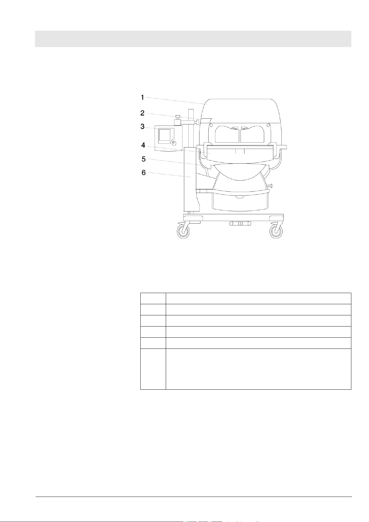
Caleo consists of a canopy, a display housing, a basic housing, an aggregate
housing, and a trolley.
Figure 1 Front view of the Caleo
Legend
1 Canopy
2 Display housing
3 Basic housing
4 Aggregate housing
5 Drawer (option)
6 Trolley
- non-adjustable trolley
- electrically adjustable trolley (optional)
Version 2.2_ Released_Printed on_24.10.07_F6150000_Function_description.fm
All rights reserved. Copyright reserved.
6150.000
7

Function Description Caleo
1.1 Canopy The canopy is a transparent acrylic cover. It is designed to sustain the set
patient's environment. The canopy is mounted on column elements.
When the front door or the hand ports are open, a warm air "curtain" ensures
that the air temperature in the patient compartment does not decrease.
The canopy comprises the canopy cover, a catch borehole, a double-wall
(option) and holders.
Figure 2 Front view of the Caleo canopy
Legend
1 Catch borehole
2 Canopy cover
3 Double wall (optional)
4Holders
8
6150.000
Version 2.2_ Released_Printed on_24.10.07_F6150000_Function_description.fm
All rights reserved. Copyright reserved.

Caleo Function Description
1.2 Sensor unit The sensor unit is mounted on two column elements. The sensor unit mea-
sures the environment inside the patient compartment.
The sensor unit (Figure 3/1) contains the following subassemblies:
–Housing
– WT2 Sensor PCB
– Integrated O2 Monitor PCB
– Alarm PCB with alarm light
Figure 3 Left view of the Caleo
The sensor unit contains the following sensors:
– Air-temperature sensors
– Oxygen sensor(s) (optional)
– Second oxygen sensor for oxygen regulation (optional)
– Humidity sensor (optional)
1.2.1 WT2 Sensor PCB The WT2 Sensor PCB measures the air temperature, skin temperature,
humidity, and oxygen. These values are transmitted to the microcontroller of
the WT2 Actuator PCB.
The WT2 Sensor PCB has the following subassemblies:
– Measurement of the patient's skin temperature
– Measurement of the air temperature and independent excess tempera-
ture monitoring
– Communication, A/D conversion, and electrical isolation
Version 2.2_ Released_Printed on_24.10.07_F6150000_Function_description.fm
All rights reserved. Copyright reserved.
6150.000
9
Function Description Caleo
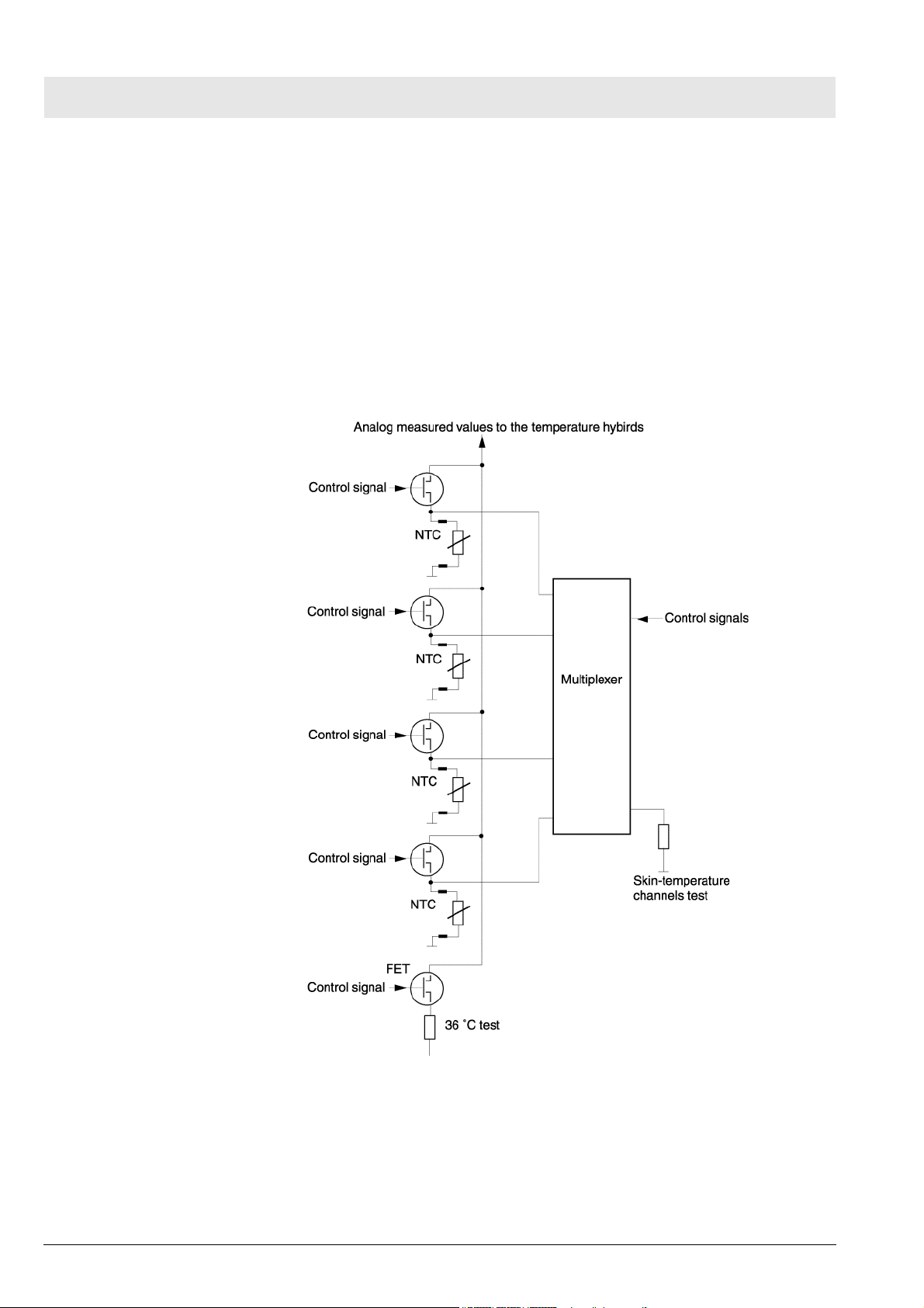
Measurement of the skin temperature
The control signals from the shift registers switch the individual skin-temperature measuring channels to the temperature hybrids. For the multiplexer to be
able to test the skin-temperature measuring channels, it switches a parallel
resistor to the respective skin-temperature measuring channel during operation.
The microcontroller of the WT2 Sensor PCB tests the accuracy of the temperature hybrids during the 10-minute test. To do so, a control signal is transmitted to a FET. Thus, the 36 °C resistor is switched to the input of the
temperature hybrids.
10
Figure 4 Block diagram of the WT2 Sensor PCB, skin-temperature mea-
surement
6150.000
Version 2.2_ Released_Printed on_24.10.07_F6150000_Function_description.fm
All rights reserved. Copyright reserved.
Caleo Function Description
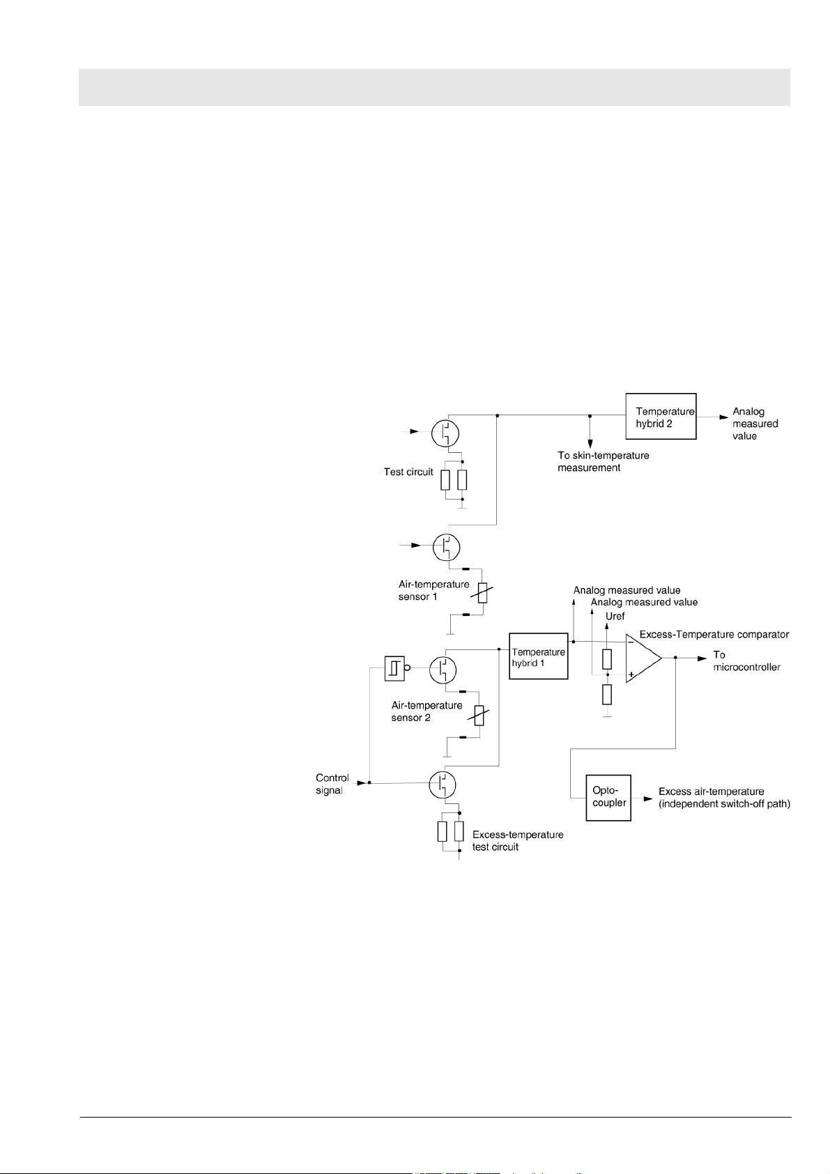
Measurement of the air temperature and independent excess temperature monitoring
The analog measured values of the air temperature reach temperature hybrid
1. The downstream excess-temperature comparator makes sure the air temperature in the patient compartment does not exceed 40.2 °C. If the air temperature is higher, a logic circuit on the WT2 Actuator PCB switches off the
air heater.
During the 10-minute test, the excess-temperature test circuit simulates a
temperature of 40.2 °C. During this period, the microcontroller monitors the
function of the excess-temperature monitoring. An additional test circuit monitors also the air-temperature sensor 1.
Version 2.2_ Released_Printed on_24.10.07_F6150000_Function_description.fm
All rights reserved. Copyright reserved.
6150.000
Figure 5 Block diagram of the WT2 Sensor PCB, air-temperature mea-
surement and independent excess-temperature monitoring
11

Function Description Caleo
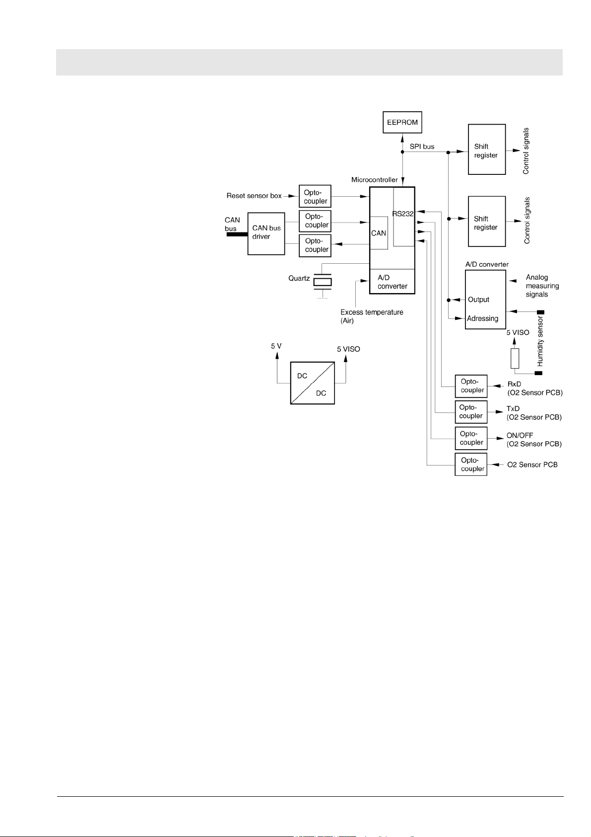
Communication, A/D conversion, and electrical isolation
The microcontroller controls and monitors the WT2 Sensor PCB functions.
A quartz clocks the microcontroller (with integrated CAN/RS232 interface)
with a frequency of 8 MHz.
Shift registers use the SPI bus to control non-time-critical input and output
connections.
The microcontroller has serial connections, input/output connections, interruptible connections, and analog input connections for measurement. Optocouplers electrically isolate the input and output signals. The integrated
RS232 interface of the microcontroller connects the WT2 Sensor PCB with
the O2 Sensor PCB. The microcontroller can switch on/off the
O2 Sensor PCB.
The CAN bus driver connects the microcontroller with the WT2 Actuator PCB.
The DC/DC converter generates the 5 VISO voltage from the 5V operating
voltage.
An EEPROM stores board-specific data. A/D converter and EEPROM are
controlled with the SPI bus. The A/D converter integrated in the microcontroller receives the signal from the independent excess-temperature monitoring.
The A/D converter measures the analog measuring signals (humidity
(optional feature), air temperature, skin temperature, and 5 VISO voltage).
12
6150.000
Version 2.2_ Released_Printed on_24.10.07_F6150000_Function_description.fm
All rights reserved. Copyright reserved.
Caleo Function Description
Figure 6 Block diagram of the WT2 Sensor PCB (communication, A/D
conversion, and electrical isolation)
Version 2.2_ Released_Printed on_24.10.07_F6150000_Function_description.fm
All rights reserved. Copyright reserved.
6150.000
13
Function Description Caleo
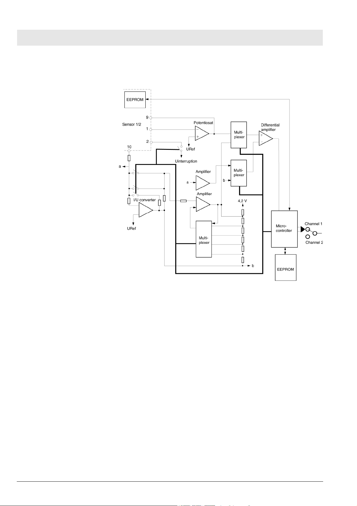
1.2.2 Integrated O2 Monitor PCB The Integrated O2 Monitor PCB receives the converted voltage from the oxy-
gen sensor.
Figure 7 Block diagram of the Integrated O2 Monitor PCB
Skin-temperature sensor socket
The skin-temperature sensor connectors are connected to the skin-temperature sensor sockets.
Skin-temperature sensors
Disposable skin-temperature sensors measure the patient's skin temperature.
Oxygen Measurement (optional)
Caleo is provided with an oxygen sensor for measurement of the oxygen content. The oxygen measurement range is 19 vol.% O2 to 99 vol.% O2. The
microcontroller does not regulate the set oxygen value. Alarm limits can be
adjusted or disabled completely.
Oxygen Regulation (optional)
The microcontroller compares the set oxygen value with the actual oxygen
value. The microcontroller automatically adapts the actual oxygen value to
the set oxygen value.
14
6150.000
Version 2.2_ Released_Printed on_24.10.07_F6150000_Function_description.fm
All rights reserved. Copyright reserved.

Caleo Function Description
Humidity sensor (optional)
The humidity sensor is mounted on the sensor unit. The humidity sensor
measure the air humidity in the patient compartment.
Humidity Control (optional)
The performance value of the water boiler can be adjusted. However, the
microcontroller does not readjust these performance values.
Humidity Regulation (optional)
The microcontroller compares the set performance values with the actual performance values of the water boiler. The microcontroller automatically adapts
the actual performance values of the water boiler to the set performance values.
1.2.3 Alarm PCB with alarm
light
The alarm light is mounted on the sensor unit. If an alarm occurs, the microcontroller on the WT2 Controller PCB triggers the alarm light.
Figure 8 Block diagram of Alarm PCB with alarm light
Version 2.2_ Released_Printed on_24.10.07_F6150000_Function_description.fm
All rights reserved. Copyright reserved.
6150.000
15
Function Description Caleo
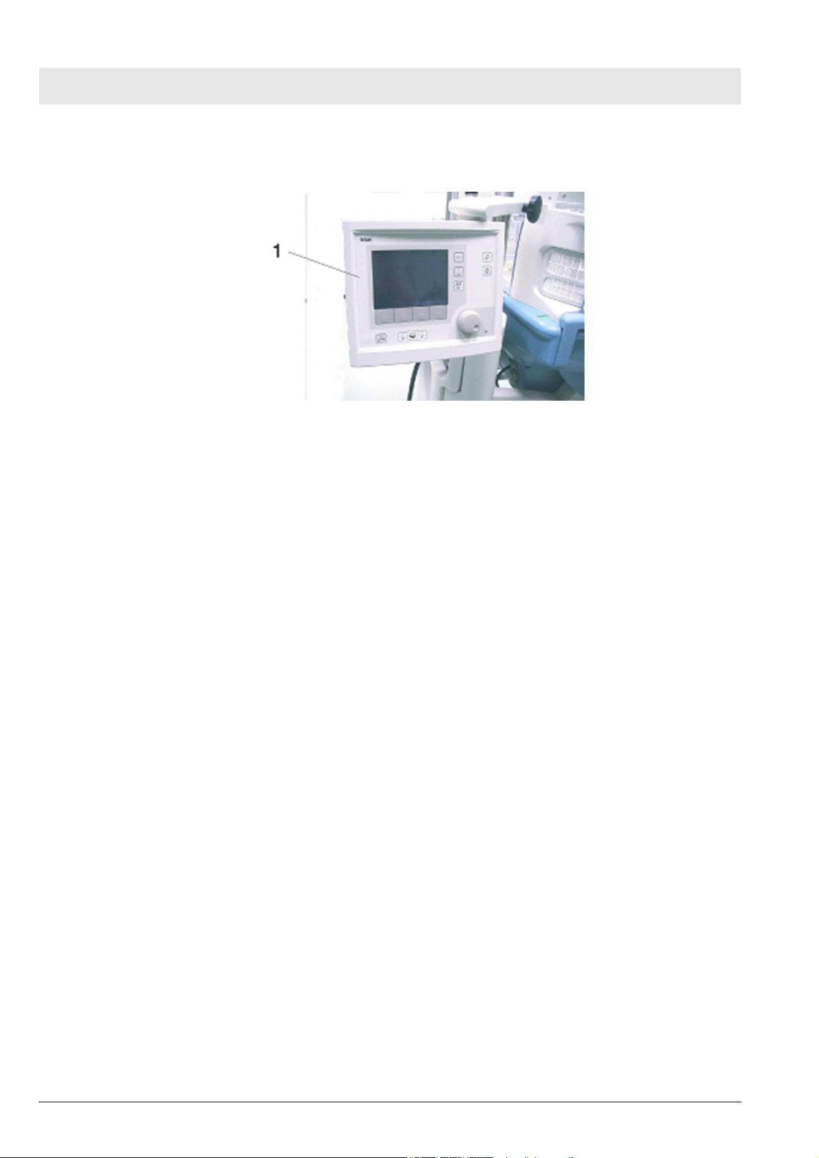
1.3 Display housing The display housing (Figure 9/1) is Caleo's display and control unit.
Figure 9 Front view of the display housing
The display housing contains the following subassemblies:
–Housing
– Membrane keypad
– EL display (electroluminescent display)
– WT2 Controller PCB
– Lithium battery
– Shaft encoder with control knob
– Loudspeaker
– WT Interface PCB (optional)
1.3.1 Housing The housing contains the membrane keypad, the EL display, the
WT2 Controller PCB, the lithium battery, the shaft encoder with control knob,
the loudspeaker, and the WT2 Interface PCB (optional).
Version 2.2_ Released_Printed on_24.10.07_F6150000_Function_description.fm
All rights reserved. Copyright reserved.
16
6150.000
Caleo Function Description
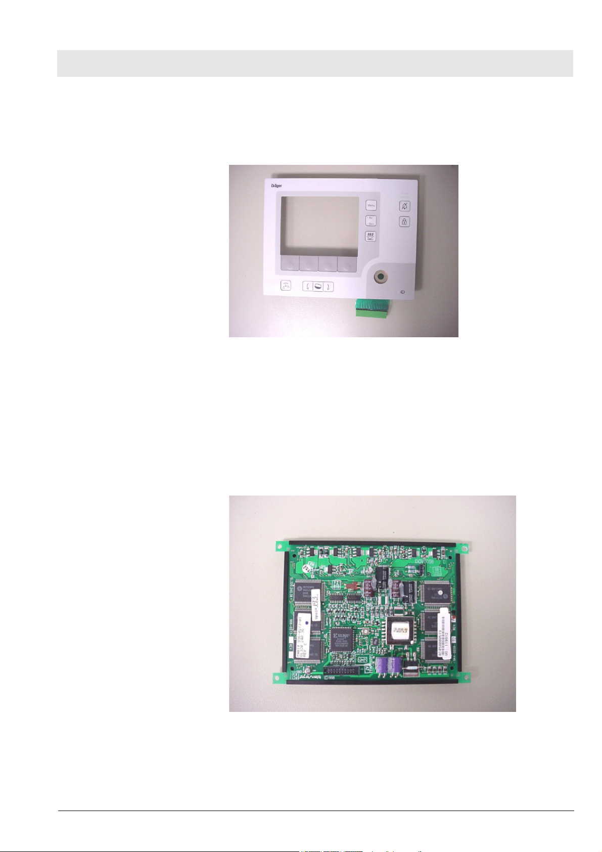
1.3.2 Membrane keypad The membrane keypad has 12 keys and 7 LEDs. The membrane keypad is
used to enter patient parameters. The LEDs on the keys indicate which function is currently selected.
Figure 10 Membrane keypad
1.3.3 EL display (electroluminescent display)
The EL display shows plain text messages. The EL display has a resolution
of 320 x 240 pixels and adapts automatically to lighting conditions (brightness
and contrast).
The EL display consists of an electroluminescent glass plate and the control
electronics. An integrated DC/DC converter generates the operating voltages
5 VDC and 12 VDC.
Version 2.2_ Released_Printed on_24.10.07_F6150000_Function_description.fm
All rights reserved. Copyright reserved.
6150.000
Figure 11 EL display
17

Function Description Caleo
1.3.4 WT2 Controller PCB The WT2 Controller board, hereinafter called WT2 Controller PCB, controls
and monitors Caleo's functions. The CAN interface connects the microcontroller with the WT2 Actuator PCB.
In the event of a fault, the WT2 Controller PCB switches off consumers and
an audible alarm sounds.
The WT2 Controller PCB comprises the following sub-assemblies/components:
– Microcontroller
–Quartz
– Read-only memory (ROM)
– EEPROM
–Flash PROM
– Random access memory (RAM)
– GoldCap evaluation
– Real-time clock (RTC)
– Lithium battery
– Powerfail Oscillator
– Display Controller
–LED Control
– Keypad Driver
– CAN Controller and CAN Driver
– Loudspeaker Control
– Piezo Alarm Generator
– Counter (Watchdog)
– Service interface
– Service LEDs
18
6150.000
Version 2.2_ Released_Printed on_24.10.07_F6150000_Function_description.fm
All rights reserved. Copyright reserved.
Caleo Function Description
Version 2.2_ Released_Printed on_24.10.07_F6150000_Function_description.fm
All rights reserved. Copyright reserved.
6150.000
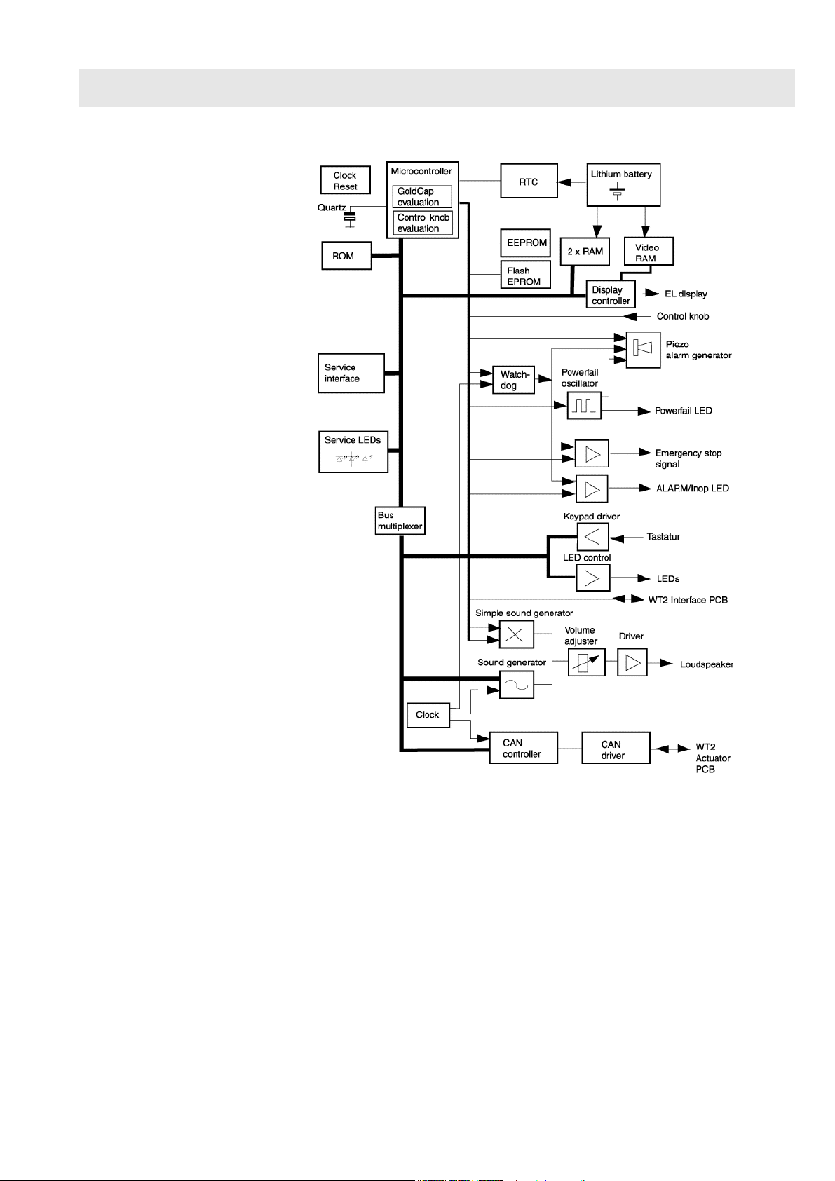
Figure 12 Block diagram of the WT2 Controller PCB
Microcontroller
The microcontroller controls Caleo's functions. A quartz clocks the microcontroller with 32.768 kHz. The random-access memory (RAM) temporarily
stores parameters for the microcontroller. The flash PROM contains the software program. The EEPROM contains the configuration data of the device.
The microcontroller uses the control knob evaluation to read in the settings
selected with the control knob. The microcontroller monitors that no voltage
drop of the GoldCap capacitor occurs due to contact resistances in the wiring.
Real-Time Clock (RTC)
The RTC displays the correct time and date on the EL display.
19

Function Description Caleo
Lithium battery
When the device is switched off, the lithium battery powers the randomaccess memories (2x RAM and video RAM) and the RTC.
Powerfail Oscillator
The GoldCap capacitor powers the powerfail oscillator. If the mains voltage
fails during operation, the powerfail oscillator generates an alarm and triggers
the piezo alarm generator.
Display Controller
The display controller controls the EL display. The display controller consists
of a programmable module, a display control module, and a data bus driver.
The microcontroller provides the display controller with current data. In addition, trend data can be read out of the video RAM.
LED Control
The microcontroller controls the LEDs using transistors.
Keypad Driver
The microcontroller uses a driver module to read in keypad entries.
CAN Controller and CAN Driver
The CAN controller and the CAN bus driver connect the microcontroller with
the WT2 Actuator PCB.
Loudspeaker control
The microcontroller uses the sound generator to generate control signals. A
series-connected driver preprocesses the signals for the loudspeaker. The
software makes it possible to adjust the sound volume.
Piezo Alarm Generator
The operating voltage of the piezo alarm generator is +5 V. If the mains voltage fails, the GoldCap capacitor powers the piezo alarm generator. The piezo
alarm generator makes it possible to generate audible alarms should the
mains power or the device fail.
Counter (Watchdog)
20
The counter (watchdog) monitors the software program sequence of the
microcontroller. The microcontroller resets the counter module at regular
intervals (250 ms).
Service interface socket
A laptop computer can be connected to the service interface socket for servicing purposes.
6150.000
Version 2.2_ Released_Printed on_24.10.07_F6150000_Function_description.fm
All rights reserved. Copyright reserved.
Caleo Function Description
Service LEDs
The service LEDs indicate the function of the microcontroller and of the keypad.
1.3.5 Loudspeaker In the event of a failure, the loudspeaker emits an audible signal.
1.3.6 Shaft encoder with control knob
1.3.7 WT2 Interface PCB
(option)
Turning the control knob will change the set patient parameters. Pressing the
control knob will store the selected values or the device configurations.
The WT2 Interface PCB makes it possible to create a connection between
Caleo and a laptop computer. Integrated modules adjust the levels and isolate the connection.
1.4 Basic housing The basic housing is mounted on the wheeled frame. The mattress tray and
the mattress are placed inside the basic housing.
The basic housing consists of the following parts: top side, base, drawer,
intermediate element, air duct with sealing, and scales (optional).
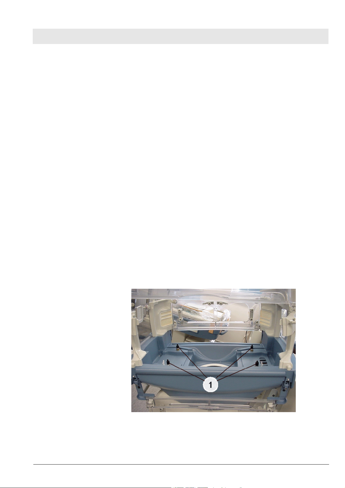
1.4.1 Scale (option) Scales are used for weighing premature infants. The scales are operated
from the display housing.
The scales comprise four weighing elements (1), which are located underneath the mattress tray, and the measuring and evaluation electronics.
The microcontroller stores the measured weight and displays it on the EL display. The trend display shows the measured weight of at least the last 5 days.
The most recent weight is displayed in numerical format including the date of
measurement. The weighing range is 0 to 10 kg.
Version 2.2_ Released_Printed on_24.10.07_F6150000_Function_description.fm
All rights reserved. Copyright reserved.
6150.000
Figure 13 Front view of Caleo, weighing elements
21

Function Description Caleo
1.4.2 Mattress tray The mattress tray is made of plastic. The mattress tray is placed inside the
basic housing.
Mattress
Caleo without mattress heater is equipped with a standard mattress.
1.4.3 Mattress tray with heating foil
The mattress tray is provided with a heating foil. When the mattress tray
heater is on, the heating foil is supplied with 24 V operating voltage. The
heating foil heats up.
WARNING
Always use a gel mattress when operating the unit with a mattress
heater.
Mattress
Caleo with mattress heater is equipped with a gel mattress.
1.5 Water container The water container is mounted on the basic housing and has a filling volume
of 2.3 L. The water container has specific colors which allow to see the current water level from the outside.
1.6 Aggregate housing The aggregate housing is located underneath the basic housing; it contains
actuators and internal control elements.
The aggregate housing contains the following subassemblies:
– Toroidal transformer
–E-box
– Water boiler with float and thermo switches (option)
– Air heater with heating element and thermo switches
– Air-temperature sensor
– Hall sensor
–Fan
– Filter box
– Pneumatics for O2 control (optional)
1.6.1 Toroidal transformer The toroidal-core transformer transforms the mains input voltage into the fol-
lowing mains output voltages:
– 24 VAC
– 12 VAC
1.6.2 E-box The E-box comprises the E-box housing, the WT2 Actuator PCB and the
WT2 Mattress PCB (optional feature).
E-Box Housing
The E-box housing protects the printed circuit board from external damage.
The E-box housing contains the WT2 Actuator PCB and the WT2 Mattress
PCB (optional feature).
22
6150.000
Version 2.2_ Released_Printed on_24.10.07_F6150000_Function_description.fm
All rights reserved. Copyright reserved.

Caleo Function Description
WT2 Actuator PCB
The WT2 Actuator PCB controls and monitors functions.
The WT2 Actuator PCB comprises the following subassemblies:
– Communication
– Power Pack for Low Voltages
– Control and switch-off of air heater and water boiler
– Feedback signals from air heater and water boiler
– Monitoring and testing of air heater and water boiler
– Control and monitoring of adjustable column height and bed inclination
–Fan
– O2 pneumatics
– Temperature measuring circuit
Version 2.2_ Released_Printed on_24.10.07_F6150000_Function_description.fm
All rights reserved. Copyright reserved.
6150.000
23
Function Description Caleo
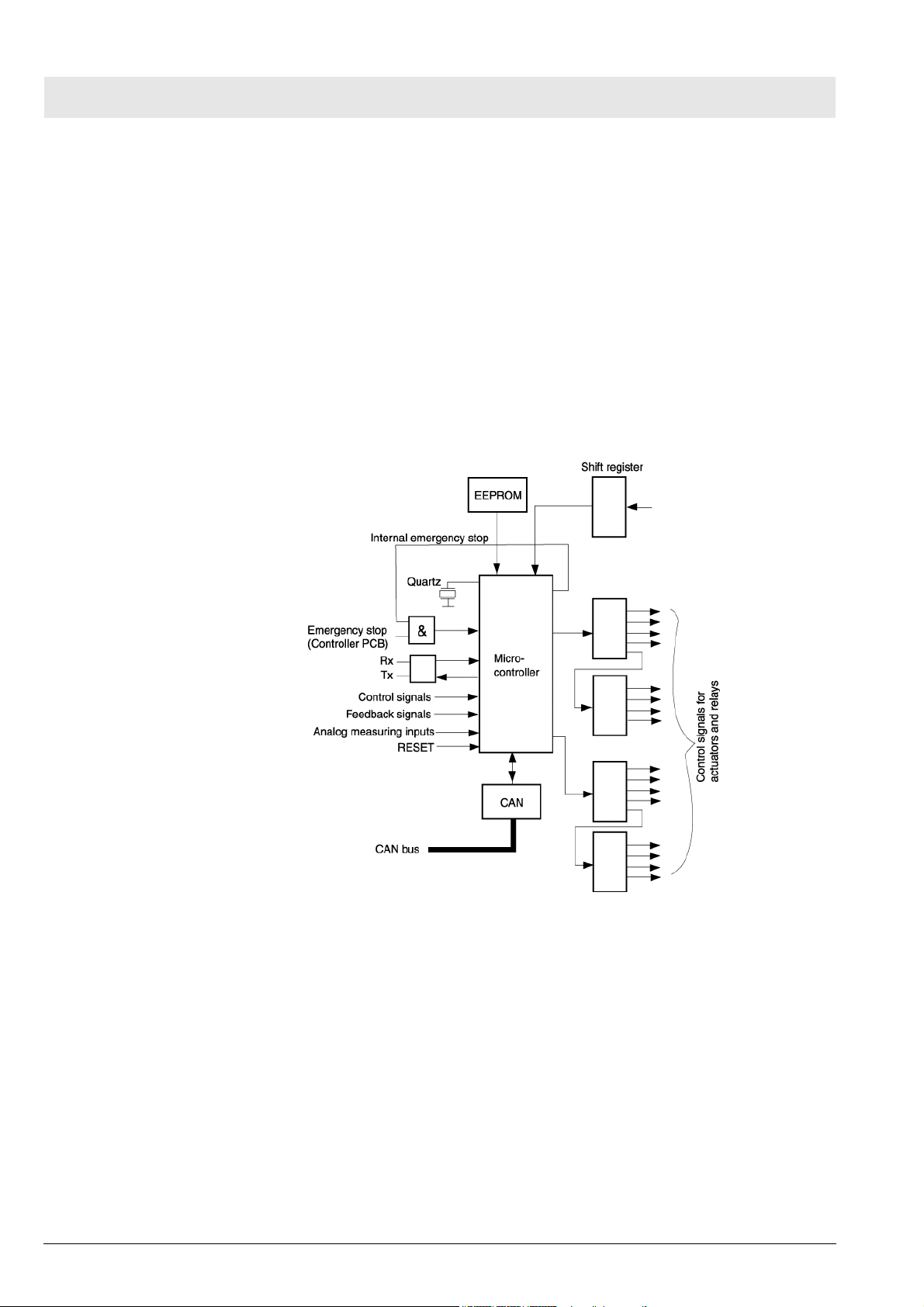
Communication
The microcontroller controls and monitors the WT2 Sensor PCB functions. A
quartz clocks the microcontroller with 8 MHz. Shift registers use the SPI bus
to control non-time-critical input and output connections. The EEPROM
stores board-specific data. The memory area of the EEPROM is 1 kB.
The input and output connections (ports) of the microcontroller are assigned
as follows:
– Serial input and output connections to the shift registers
– Input/output connections (Tx, Rx, CAN)
– Interruptible input connections (feedback signals)
– Analog measuring inputs
24
Figure 14 Block diagram 2 of the WT2 Actuator PCB (communication)
6150.000
Version 2.2_ Released_Printed on_24.10.07_F6150000_Function_description.fm
All rights reserved. Copyright reserved.