

Dräger Medical C450 QT, C400 QT User Manual
Air-Shields® Isolette® Infant Incubators
WARNING:
For a full understanding of the performance
characteristics of this equipment, the user
should carefully read this manual before
operating.
xxxxxxxx
Models C400 QT® and
C450 QT®
Operating Instructions

iv

PROPRIETARY AND CONFIDENTIAL DRAFT 19 Nov 04
Table of Contents
Section 1: Symbol Definition and Intended Use
Symbol Definition. . . . . . . . . . . . . . . . . . . . . . . . . . . . . . . . . . . . . . . . . . . . . . . . . . . . . . . . . . . . . . 1 - 1
Technical Definitions . . . . . . . . . . . . . . . . . . . . . . . . . . . . . . . . . . . . . . . . . . . . . . . . . . . . . . . . . . . 1 - 4
Intended Use . . . . . . . . . . . . . . . . . . . . . . . . . . . . . . . . . . . . . . . . . . . . . . . . . . . . . . . . . . . . . . . . . . 1 - 4
Section 2: Introduction, Features, and Specifications
Introduction. . . . . . . . . . . . . . . . . . . . . . . . . . . . . . . . . . . . . . . . . . . . . . . . . . . . . . . . . . . . . . . . . . . 2 - 1
Functional Description . . . . . . . . . . . . . . . . . . . . . . . . . . . . . . . . . . . . . . . . . . . . . . . . . . . . . . . 2 - 2
Features. . . . . . . . . . . . . . . . . . . . . . . . . . . . . . . . . . . . . . . . . . . . . . . . . . . . . . . . . . . . . . . . . . . . . . 2 - 3
Standard Features . . . . . . . . . . . . . . . . . . . . . . . . . . . . . . . . . . . . . . . . . . . . . . . . . . . . . . . . . . . 2 - 3
Temperature Control. . . . . . . . . . . . . . . . . . . . . . . . . . . . . . . . . . . . . . . . . . . . . . . . . . . . . . 2 - 3
Alarms. . . . . . . . . . . . . . . . . . . . . . . . . . . . . . . . . . . . . . . . . . . . . . . . . . . . . . . . . . . . . . . . . 2 - 4
Continuously Variable Mattress Tilt Mechanism. . . . . . . . . . . . . . . . . . . . . . . . . . . . . . . . 2 - 6
Quiet Latch Access Doors . . . . . . . . . . . . . . . . . . . . . . . . . . . . . . . . . . . . . . . . . . . . . . . . . 2 - 6
Optional Features . . . . . . . . . . . . . . . . . . . . . . . . . . . . . . . . . . . . . . . . . . . . . . . . . . . . . . . . . . . 2 - 6
Accessories . . . . . . . . . . . . . . . . . . . . . . . . . . . . . . . . . . . . . . . . . . . . . . . . . . . . . . . . . . . . . . . . 2 - 7
Specifications . . . . . . . . . . . . . . . . . . . . . . . . . . . . . . . . . . . . . . . . . . . . . . . . . . . . . . . . . . . . . . . . . 2 - 7
Standard Features . . . . . . . . . . . . . . . . . . . . . . . . . . . . . . . . . . . . . . . . . . . . . . . . . . . . . . . . . . . 2 - 8
Optional Features . . . . . . . . . . . . . . . . . . . . . . . . . . . . . . . . . . . . . . . . . . . . . . . . . . . . . . . . . . 2 - 10
Alarms. . . . . . . . . . . . . . . . . . . . . . . . . . . . . . . . . . . . . . . . . . . . . . . . . . . . . . . . . . . . . . . . . . . 2 - 10
Regulation, Standards, and Codes . . . . . . . . . . . . . . . . . . . . . . . . . . . . . . . . . . . . . . . . . . . . . 2 - 11
Device Classification . . . . . . . . . . . . . . . . . . . . . . . . . . . . . . . . . . . . . . . . . . . . . . . . . . . . 2 - 11
Electromagnetic Compatibility (EMC) Guidance and Manufacturer’s Declaration . . . . 2 - 11
Section 3: Precautions and Safety Tips
Precautions . . . . . . . . . . . . . . . . . . . . . . . . . . . . . . . . . . . . . . . . . . . . . . . . . . . . . . . . . . . . . . . . . . . 3 - 1
Electrical Precautions . . . . . . . . . . . . . . . . . . . . . . . . . . . . . . . . . . . . . . . . . . . . . . . . . . . . . . . . 3 - 1
Explosion Precautions. . . . . . . . . . . . . . . . . . . . . . . . . . . . . . . . . . . . . . . . . . . . . . . . . . . . . . . . 3 - 1
Oxygen Precautions . . . . . . . . . . . . . . . . . . . . . . . . . . . . . . . . . . . . . . . . . . . . . . . . . . . . . . . . . 3 - 2
Electromagnetic Compatibility Precautions . . . . . . . . . . . . . . . . . . . . . . . . . . . . . . . . . . . . . . . 3 - 3
Safety Tips . . . . . . . . . . . . . . . . . . . . . . . . . . . . . . . . . . . . . . . . . . . . . . . . . . . . . . . . . . . . . . . . . . . 3 - 4
Swivel Monitor Shelves . . . . . . . . . . . . . . . . . . . . . . . . . . . . . . . . . . . . . . . . . . . . . . . . . . . . . . 3 - 7
Warning Labels. . . . . . . . . . . . . . . . . . . . . . . . . . . . . . . . . . . . . . . . . . . . . . . . . . . . . . . . . . . . . . . . 3 - 8
Section 4: Installation and Assembly
Installation . . . . . . . . . . . . . . . . . . . . . . . . . . . . . . . . . . . . . . . . . . . . . . . . . . . . . . . . . . . . . . . . . . . 4 - 1
Unpacking. . . . . . . . . . . . . . . . . . . . . . . . . . . . . . . . . . . . . . . . . . . . . . . . . . . . . . . . . . . . . . . . . 4 - 1
Assembly . . . . . . . . . . . . . . . . . . . . . . . . . . . . . . . . . . . . . . . . . . . . . . . . . . . . . . . . . . . . . . . . . . . . 4 - 2
Incubators Equipped with the Standard Cabinet Stand . . . . . . . . . . . . . . . . . . . . . . . . . . . . . . 4 - 2
i

PROPRIETARY AND CONFIDENTIAL DRAFT 19 Nov 04
Incubators Equipped with a Variable Height Adjustable (VHA) Stand. . . . . . . . . . . . . . . . . . 4 - 3
Warm Weigh® Infant Scale, Model I20 (Accessory) . . . . . . . . . . . . . . . . . . . . . . . . . . . . . . . 4 - 4
General Operation and Functional Checkout Procedure . . . . . . . . . . . . . . . . . . . . . . . . . . . . . 4 - 5
Section 5: Instructions for Use
Instructions for Use. . . . . . . . . . . . . . . . . . . . . . . . . . . . . . . . . . . . . . . . . . . . . . . . . . . . . . . . . . . . . 5 - 1
Air Mode. . . . . . . . . . . . . . . . . . . . . . . . . . . . . . . . . . . . . . . . . . . . . . . . . . . . . . . . . . . . . . . . . . 5 - 3
To Select: . . . . . . . . . . . . . . . . . . . . . . . . . . . . . . . . . . . . . . . . . . . . . . . . . . . . . . . . . . . . . . 5 - 3
Auxiliary Air Probe . . . . . . . . . . . . . . . . . . . . . . . . . . . . . . . . . . . . . . . . . . . . . . . . . . . . . . 5 - 3
Baby Mode . . . . . . . . . . . . . . . . . . . . . . . . . . . . . . . . . . . . . . . . . . . . . . . . . . . . . . . . . . . . . . . . 5 - 4
Oxygen Therapy . . . . . . . . . . . . . . . . . . . . . . . . . . . . . . . . . . . . . . . . . . . . . . . . . . . . . . . . . . . . 5 - 5
Humidity Reservoir. . . . . . . . . . . . . . . . . . . . . . . . . . . . . . . . . . . . . . . . . . . . . . . . . . . . . . . . . . 5 - 7
Controls, Indicators, and Connectors . . . . . . . . . . . . . . . . . . . . . . . . . . . . . . . . . . . . . . . . . . . . 5 - 8
Optional Features . . . . . . . . . . . . . . . . . . . . . . . . . . . . . . . . . . . . . . . . . . . . . . . . . . . . . . . . . . 5 - 14
Accessories . . . . . . . . . . . . . . . . . . . . . . . . . . . . . . . . . . . . . . . . . . . . . . . . . . . . . . . . . . . . . . . 5 - 16
Cabinets and Drawers. . . . . . . . . . . . . . . . . . . . . . . . . . . . . . . . . . . . . . . . . . . . . . . . . . . . 5 - 17
Swivel Shelves . . . . . . . . . . . . . . . . . . . . . . . . . . . . . . . . . . . . . . . . . . . . . . . . . . . . . . . . . 5 - 17
Section 6: Cleaning, Maintenance, Replacement Parts, and Storage and Handling
Cleaning . . . . . . . . . . . . . . . . . . . . . . . . . . . . . . . . . . . . . . . . . . . . . . . . . . . . . . . . . . . . . . . . . . 6 - 1
General Cleaning . . . . . . . . . . . . . . . . . . . . . . . . . . . . . . . . . . . . . . . . . . . . . . . . . . . . . . . . . . . 6 - 1
Cleaning Agents . . . . . . . . . . . . . . . . . . . . . . . . . . . . . . . . . . . . . . . . . . . . . . . . . . . . . . . . . . . . 6 - 1
Steam Cleaning. . . . . . . . . . . . . . . . . . . . . . . . . . . . . . . . . . . . . . . . . . . . . . . . . . . . . . . . . . . . . 6 - 2
Cleaning Difficult to Access Areas . . . . . . . . . . . . . . . . . . . . . . . . . . . . . . . . . . . . . . . . . . . . . 6 - 2
Cleaning Painted Surfaces . . . . . . . . . . . . . . . . . . . . . . . . . . . . . . . . . . . . . . . . . . . . . . . . . . . . 6 - 2
Cleaning Clear Plastic and Acrylic Surfaces . . . . . . . . . . . . . . . . . . . . . . . . . . . . . . . . . . . . . . 6 - 2
Disinfecting. . . . . . . . . . . . . . . . . . . . . . . . . . . . . . . . . . . . . . . . . . . . . . . . . . . . . . . . . . . . . . . . 6 - 2
Disassembly for Cleaning . . . . . . . . . . . . . . . . . . . . . . . . . . . . . . . . . . . . . . . . . . . . . . . . . . . . 6 - 2
Cleaning . . . . . . . . . . . . . . . . . . . . . . . . . . . . . . . . . . . . . . . . . . . . . . . . . . . . . . . . . . . . . . . . . . 6 - 5
Cleaning the Skin Probe (Model C450 QT® Isolette® Infant Incubator Only). . . . . . . . . 6 - 5
Cleaning the Humidity Chamber and Fill Pipe, Air Intake Tube, Access Door Gaskets,
and Tubing Access Gaskets . . . . . . . . . . . . . . . . . . . . . . . . . . . . . . . . . . . . . . . . . . . . . . . . 6 - 6
Cleaning the Controller. . . . . . . . . . . . . . . . . . . . . . . . . . . . . . . . . . . . . . . . . . . . . . . . . . . . 6 - 6
Cleaning the Mattress Tray and Deck Plate . . . . . . . . . . . . . . . . . . . . . . . . . . . . . . . . . . . . 6 - 7
Cleaning the Mattress Tilt Control . . . . . . . . . . . . . . . . . . . . . . . . . . . . . . . . . . . . . . . . . . . 6 - 7
Cleaning the Hood and Cabinet Stand . . . . . . . . . . . . . . . . . . . . . . . . . . . . . . . . . . . . . . . . 6 - 7
Cleaning the Air Intake Microfilter Chamber. . . . . . . . . . . . . . . . . . . . . . . . . . . . . . . . . . . 6 - 7
Assembly After Cleaning . . . . . . . . . . . . . . . . . . . . . . . . . . . . . . . . . . . . . . . . . . . . . . . . . . . . . 6 - 8
Maintenance . . . . . . . . . . . . . . . . . . . . . . . . . . . . . . . . . . . . . . . . . . . . . . . . . . . . . . . . . . . . . . . . . 6 - 11
Power Failure Alarm Battery Maintenance . . . . . . . . . . . . . . . . . . . . . . . . . . . . . . . . . . . . . . 6 - 11
ii

PROPRIETARY AND CONFIDENTIAL DRAFT 19 Nov 04
Replacement Parts. . . . . . . . . . . . . . . . . . . . . . . . . . . . . . . . . . . . . . . . . . . . . . . . . . . . . . . . . . . . . 6 - 12
Storage and Handling . . . . . . . . . . . . . . . . . . . . . . . . . . . . . . . . . . . . . . . . . . . . . . . . . . . . . . . . . . 6 - 13
Storage . . . . . . . . . . . . . . . . . . . . . . . . . . . . . . . . . . . . . . . . . . . . . . . . . . . . . . . . . . . . . . . . . . 6 - 13
Operation . . . . . . . . . . . . . . . . . . . . . . . . . . . . . . . . . . . . . . . . . . . . . . . . . . . . . . . . . . . . . . . . 6 - 13
Disposal . . . . . . . . . . . . . . . . . . . . . . . . . . . . . . . . . . . . . . . . . . . . . . . . . . . . . . . . . . . . . . . . . . . . 6 - 13
Section 7: Troubleshooting
Troubleshooting . . . . . . . . . . . . . . . . . . . . . . . . . . . . . . . . . . . . . . . . . . . . . . . . . . . . . . . . . . . . . . . 7 - 1
iii

NOTES:
PROPRIETARY AND CONFIDENTIAL DRAFT 19 Nov 04
iv

PROPRIETARY AND CONFIDENTIAL DRAFT 19 Nov 04
Section 1
Symbol Definition
and Intended Use
Symbol Definition
This manual contains different typefaces and icons designed to improve readability and increase
understanding of its content. Note the following examples:
• Standard text—used for regular information.
• Boldface text—emphasizes a word or phrase.
• NOTE:—sets apart special information or important instruction clarification.
• The symbol below highlights a WARNING or CAUTION:
Warning and Caution
– A WARNING identifies situations or actions that may af fect patient or user safety. Disregarding a
warning could result in patient or user injury.
– A CAUTION points out special procedures or precautions that personnel must follow to avoid
equipment damage.
• The symbol below highlights a CAUGHT HAZARD WARNING:
Caught Hazard Warning
• The symbol below highlights a CHEMICAL HAZARD WARNING:
Chemical Hazard Warning
• The symbol below highlights an ELECTRICAL SHOCK HAZARD WARNING:
Electrical Shock Hazard Warning
1 - 1
PROPRIETARY AND CONFIDENTIAL DRAFT 19 Nov 04
This product contains different icons designed to increase understanding. Note the following examples:
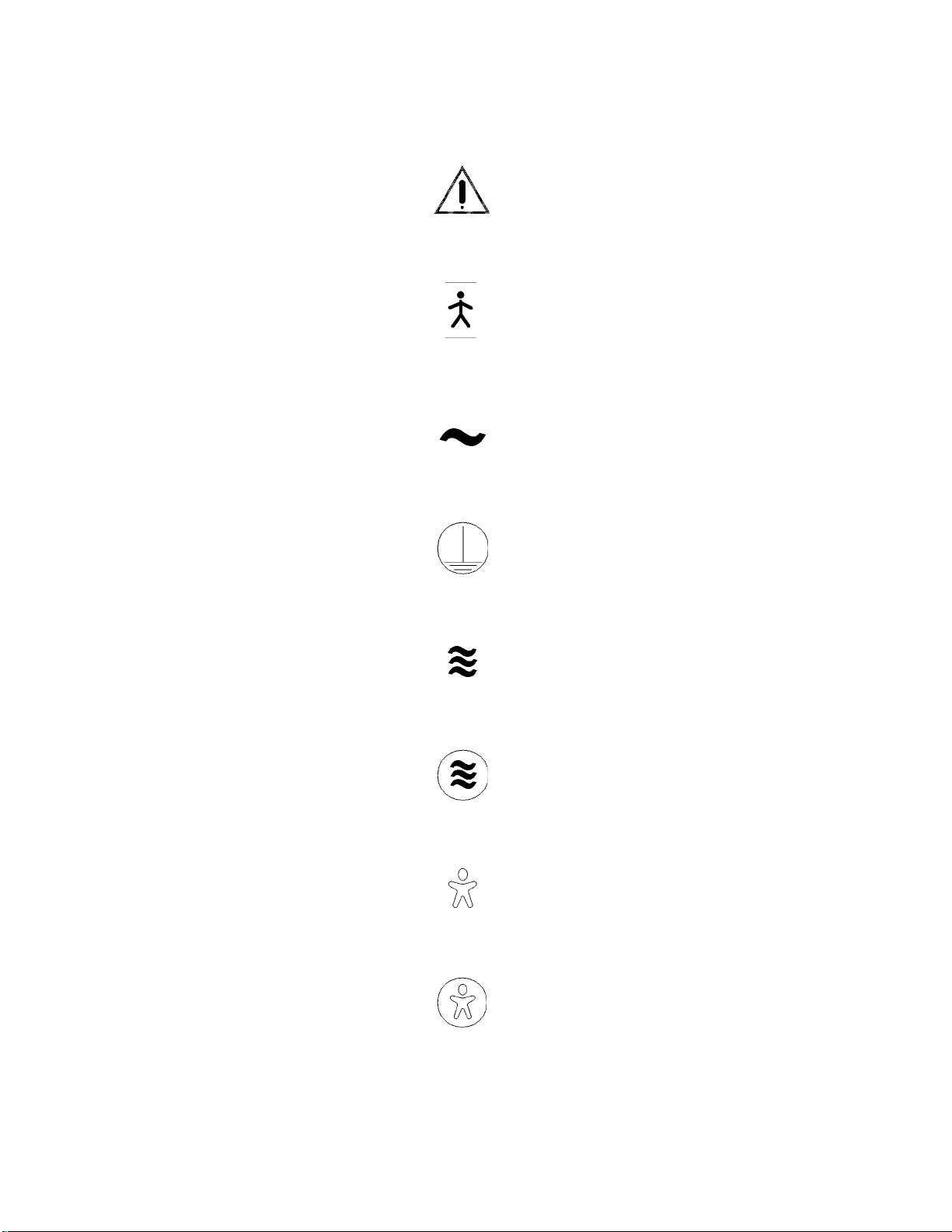
• The symbol below indicates “Attention: Consult accompanying documents:”
Attention: Consult Accompanying Documents
• The symbol below indicates “Type B equipment with an F-type floating applied part:”
Type B Equipment with an F-Type Floating Applied Part
• The symbol below indicates “AC power:”
AC Power
• The symbol below indicates “Protective earth (ground):”
Protective Earth (Ground)
• The symbol below indicates “Air Mode Control indicator:”
Air Mode Control Indicator
• The symbol below indicates “Air Mode Control selection key:”
Air Mode Control Selection Key
• The symbol below indicates “Baby Mode Control indicator:”
Baby Mode Control Indicator
• The symbol below indicates “Baby Mode Control selection key:”
Baby Mode Control Selection Key
1 - 2
PROPRIETARY AND CONFIDENTIAL DRAFT 19 Nov 04
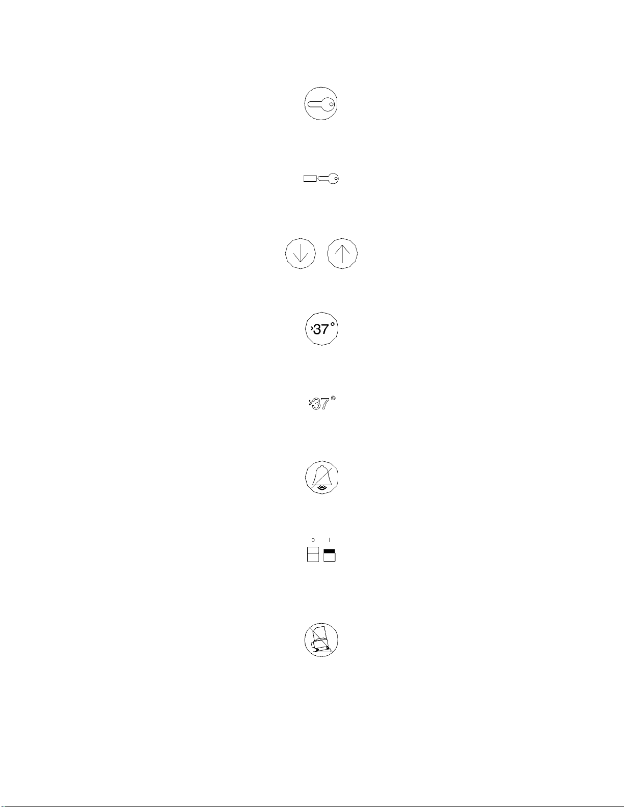
• The symbol below indicates the Keypad Lock key:
Keypad Lock Key
• The symbol below indicates the Keypad Lock indicator:
Keypad Lock Indicator
• The symbol below indicates the Set Temperature keys:
Set Temperature Keys
• The symbol below indicates the Temperature Override Mode (>37°C) selection key:
Temperature Override Mode (>37°C) Selection Key
• The symbol below indicates the Temperature Override Mode (>37°C) indicator:
Temperature Override Mode (>37°C) Indicator
• The symbol below indicates the Silence/Reset switch:
Silence/Reset
• The symbol below indicates the Power Off/On switch:
Power Off/On
• The symbol below indicates that the cabinet stand doors must remain closed to minimize the risk of
tipping during transport:
Cabinet Stand Doors Must Remain Closed
1 - 3
PROPRIETARY AND CONFIDENTIAL DRAFT 19 Nov 04
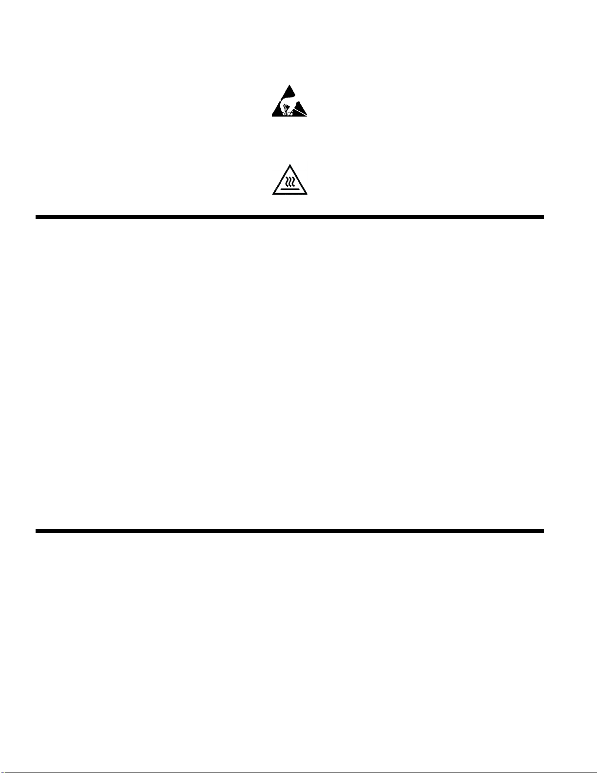
• The symbol below indicates a sensitivity to ELECTROSTATIC DISCHARGE (ESD):
Electrostatic Discharge (ESD)
• The symbol below indicates the surface could be hot.
Caution, Hot Surface
Technical Definitions
• Control zone—A plane 10 cm (4") above the mattress with an area defined by the center of four
quadrants formed by lines that divide the width and length of the mattress surface.
• Incubator temperature—The air temperature at a point 10 cm (4") above and centered over the
mattress surface.
• A verage incubator temperatur e—The average of th e maximum and minimum incubator temperature
achieved during steady temperature condition.
• Steady temperatur e condition—The condition reached when the av erage incubator temperature does
not vary more than 0.5°C over a period of 1 hour.
• Temperature overshoot—The amount by which the incubator temperature exceeds the average
incubator temperature during steady temperature condition, resulting from a change in temperature.
• Temperature rise time—The time required for the incubator temperature to rise 11°C (20°F).
• Temperature uniformity—The amount by which the average temperature at each of four points
10 cm (4") above the mattress surface differs from the average incubator temperature at steady
temperature condition. The four points are the centers of four quadrants formed by lines that divide the
width and length of the mattress surface.
• Temperature variation—The difference between the incubator temperature and the average incubator
temperature during steady temperature condition.
Intended Use
This manual provides instructions for installation, use, operator maintenance, and troubleshooting of the
Model C400 (discontinued January 2005) and C450 Isolette® Infant Incubator having QT® features, CE
Mark version. Dräger Medical cannot be responsible for the performance of the incubator if the user does
not operate the unit in accordance with the instructions, fails to follow the maintenance recommendations
of the manual, or makes any repairs with unauthorized components. Only qualified service personnel
should perform calibration and repair. Technical information is available through your local distributor.
All personnel who will be working with the unit should read, thoroughly understand, and have ready
access to this manual. Store the manual on the shelf in the cabinet stand when not in use. If there is
anything you do not understand, please contact your technical support representative for further
information.
1 - 4

DRAFT 19 May 2005
Section 2
Introduction, Features,
and Specifications
Introduction
The forced air circulation system of the incubator permits stable temperature control, uniform heat
distribution, humidification, effective isolation of the infant from airborne contaminants, and control of
oxygen concentrations. An access panel, access doors, and iris entry ports provide accessibility to the
infant. When the access panel is open, a curtain of warm air flows from beneath the front edge of the
mattress toward the top of the access panel opening; this air curtain minimizes the temperature drop
within the hood environment. The incubator is designed for use in a nursery environment having a typical
ambient operating temperature range of 20°C (68°F) to 30°C (86°F). A guard rail is standard.
On Model C450 QT® Isolette® Infant Incubator, baby or air temperature control is selected by a front
panel control. The Model C400 QT® Isolette® Infant Incubator (discontinued January 2005) is equipped
only for air temperature control. Instrumentation includes a digital display for temperature, relative
indication of heater output, and a comprehensive visual and audible alarm system, which includes an
alarm test feature.
2 - 1
DRAFT 19 May 2005
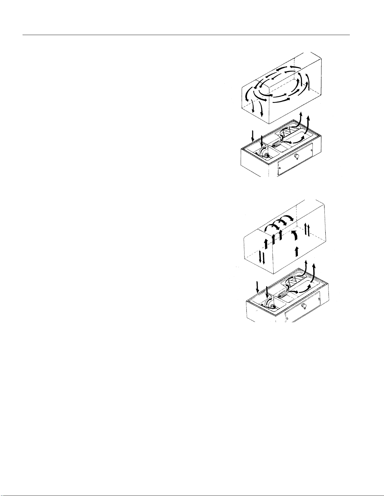
Functional Description
The forced air circulation system controls temperature,
humidity, and oxygen concentration. The motor-driven
impeller on the controller draws a controlled amount of room
air (approximately 35 litres per minute (lpm)) through the air
intake filter.
Supplemental oxygen, introduced through the oxygen input
valve on the air intake filter cover , displaces a portion of room
air to maintain the total gas intake (including oxygen) at 35
lpm. Since the impeller/filter characteristics control the
amount of room air, and the flowmeter setting controls the
amount of oxygen, predictable oxygen concentrations within
the incubator can be attained. When oxygen flow exceeds 8
lpm, a valve within the oxygen inlet housing restricts air
intake so that a higher oxygen concentration can be achieved
without excessive oxygen flow. At 12 lpm, maximum air
intake restriction is achieved.
In addition to drawing fresh, filtered air into the incubator, the
impeller internally recirculates at a much greater flow than
that of the fresh gas inflow. The total flow of fresh plus
recirculated air is directed past the air flow sensor and around
the heater with a predetermined portion being directed over
the humidity reservoir for humidification. When the access
panel of the hood is closed, the air curtain cover is closed, and
all the air enters the infant compartment up through the slot at
the right end of the main deck. After circulating within the
infant compartment, the air is then recirculated down through
the slot in the left end of the main deck. There it goes past the
temperature sensing probe, which encapsulates the air
temperature control thermistor and a high air temperature
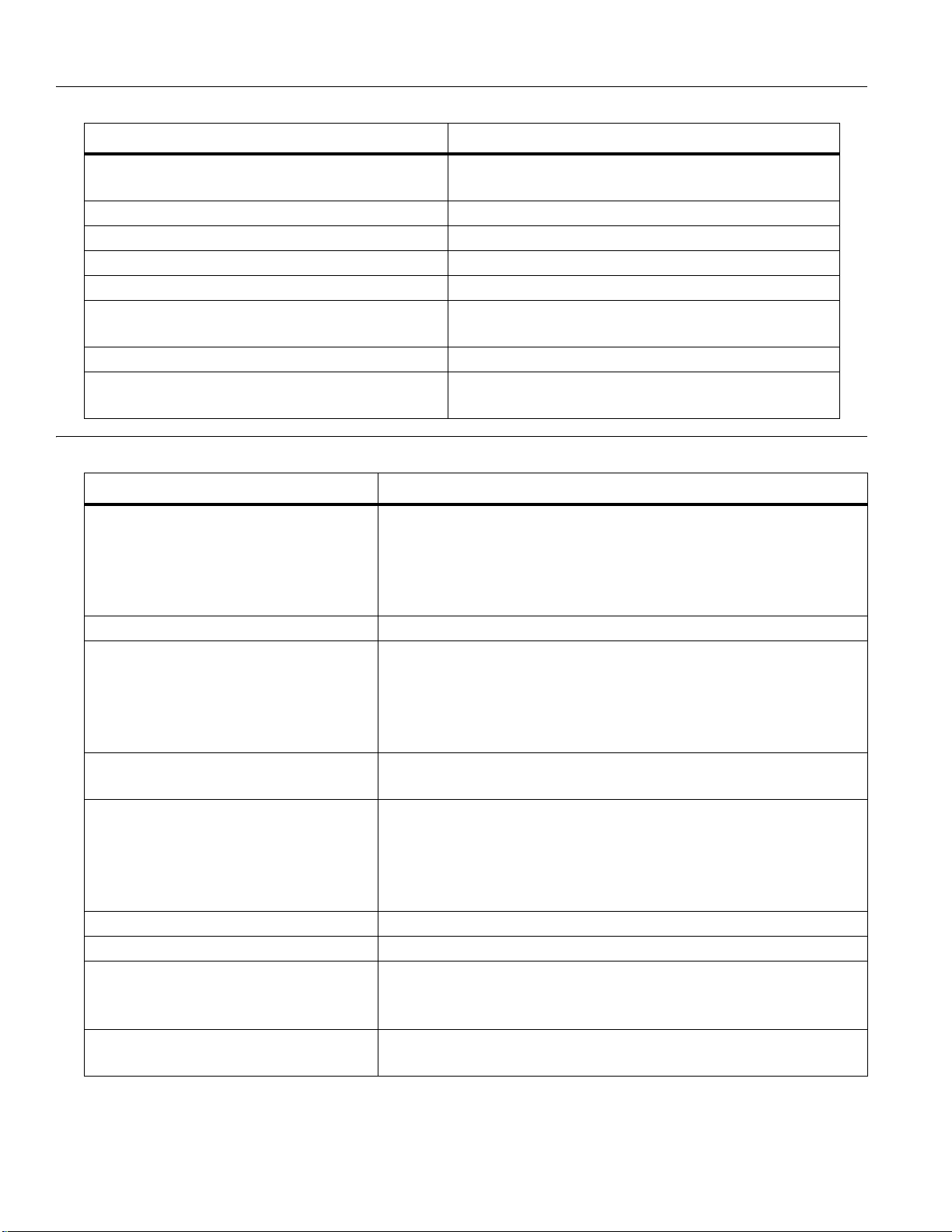
alarm thermistor, and back to the impeller. When the access
panel of the hood is open, the air curtain cover is raised,
permitting a portion of the air to flow upward past the opening creating a warm air curtain, which
minimizes the drop in air temperature in the incubator.
2 - 2

Features
DRAFT 19 May 2005
Isolette® Infant Incubator with Standard Cabinet Stand
Standard Features
Temperature Control
On the Model C450 QT® Isolette® Infant Incubator, temperature is regulated by using either incubator
air or the infant's skin temperature as the controlling parameter . A front panel key enables selection of the
desired mode. The Model C400 QT® Isolette® Infant Incubator (discontinued January 2005) provides
only Air Mode.
In either mode of operation, the heater output is proportional to the amount of heat required to maintain
the desired temperature, and the relative amount of heat being provided is indicated by the number of lit
Heater Power % indicators on the front panel. Changes in the number of lamps illuminated indicate the
amount of power required to maintain a given temperature. During Baby Mode, the Model C450 QT®
Isolette® Infant Incubator provides an indication of the degree of the infant's dependency upon the
temperature of its environment to maintain body temperature.
2 - 3

DRAFT 19 May 2005
Air Mode
In Air Mode, the air temperature can be maintained from 20°C (68°F) to 37°C (99°F) as indicated by the
Set Temp °C display setting. In Temperature Override Mode, the temperature can be maintained from
37°C (99°F) to 38.5°C (101.3°F). A probe located below deck monitors the air temperature, and
compares it with the Set Temp °C display setting. The information from this probe is supplied to the
heater control circuitry, which proportions the heater output to maintain the air temperature at the Set
Temp °C display setting. Actual air temperature is displayed by the Air Temperature °C display. A
second sensor within the air temperature probe serves as a backup to limit the incubator temperature to
between 39°C (102°F) and 40°C (104°F). At this temperature, an alarm activates, and the heater shuts off.
If desired, an auxiliary air temperature probe can control the air temperature. This probe is suspended
above the mattress through the weighing scale hole, and plugged into a special receptacle on the side of
the incubator. When plugged in, the primary air temperature control probe is disconnected, but the
backup sensor within the primary temperature probe remains connected. Thus, the auxiliary probe
controls the air temperature.
In Air Mode, the infant's temperature is a function of the air temperature and the infant's ability to
establish and maintain its own temperature. A small infant, or one with underdeveloped homeostatic
control, may not be able to maintain a stable temperature at the desired level.
Baby Mode (Model C450 QT® Isolette® Infant Incubator Only)
In Baby Mode, the infant’s skin temperature can be maintained from 34°C (93°F) to 37°C (99°F) as
indicated by the Skin Temp °C display. In Temperature Override Mode, the temperature can be
maintained from 37°C (99°F) to 37.9°C (101.3°F). A temperature sensing probe is attached directly to the
infant's skin. The information from the probe is supplied to the heater control circuitry , which proportions
the heater output to maintain the baby's temperature at the Set Temp °C setting. The actual baby
temperature appears on the Baby Temperature °C display. The Set Temp °C setting does not control air
temperature while in Baby Mode, but air temperature is still displayed. The air temperature is still limited
to 38.5°C (101.3°F). If Air Mode is selected while the skin probe remains connected, the Baby
Temperature °C display continues to display actual skin temperature, but it does not control.
If the probe is disconnected from its receptacle during Baby Mode, the Baby Temperature °C display
goes blank, and a Probe alarm activates. The high temperature alarm sensor within the air temperature
probe remains in the circuit to limit the air temperature to less than 40°C (104°F).
Alarms
Alarms are provided for power failure, system failure, inadequate air flow, probe failure, high
temperature, and variation from the set temperature. Each time the unit is turned on, the unit
automatically goes through an alarm check sequence to verify proper alarm function. After the automatic
alarm check, the low Set Temp alarm is disabled for 60 min or until the temperature reaches the Set
Temp °C setting, whichever occurs first. Each of these alarms is described below.
Air Flow
A sensor located below deck in the normal air path of the fan controls this alarm. If air flow stops due to
a fan failure, the temperature of the self-heated sensor rises, causing the Air Flow alarm indicator on the
front panel to light and produce a pulsating tone. A short-circuited, air flow sensor failure also actuates
the alarm within 10 s of the failure. This alarm is not self-resetting and cannot be silenced or canceled by
the Silence/Reset key until the alarm condition is corrected.
2 - 4

DRAFT 19 May 2005
High Temperature
A second sensor within the air temperature probe sounds this alarm if the incubator temperature reaches
39.5°C ± 0.5°C (103.1°F ± 0.9°F). A solid light and a pulsing tone indicate a High Temperature alarm.
This alarm is not self-resetting and cannot be canceled by the Silence/Reset key until the alarm condition
is corrected.
Power Failure
If primary power to the incubator is interrupted for any reason, including a disconnected power cord, an
audible alarm is activated, and the Power Fail indicator lights. To silence this alarm for two min, press
the Silence/Reset key. To deactivate this alarm, restore the primary power or set the incubator Power
switch to off.
System Fail
If an internal malfunction is detected, the System Fail indicator flashes and the alarm sounds. This alarm
is not resettable. Refer the unit to qualified service personnel.
Probe
Circuitry is provided to monitor the air, skin, and high temperature sensors for short circuits, open
circuits, or disconnected conditions and the air flow sensor for an open condition.
The Probe alarm actuates within 10 s if the air flow sensor has an open circuit a nd the temperature sensed
below the mattress deck is greater than approximately 30°C (86°F). However, if the temperature sensed
below the mattress deck is less than that, the alarm does not activate. During warm-up, it can take
anywhere from 15 to 30 min before the alarm actuates, depending on the temperature setpoint and the
ambient room temperature. If the high set temperature is below 29°C (84°F), the Probe alarm indicating
an open-circuited air flow sensor is not activated.
If a probe shorts (except for the air flow probe or High T emperature alarm probe), it also appears as a set
temperature violation, and the Set T emp alarm indicator lights. This alarm is not self-resetting and cannot
be canceled by the Silence/Reset key until the alarm condition is corrected. If a Probe alarm occurs
simultaneously with a Set Temp alarm, a shorted probe is probably the true cause of the alarm since a
shorted probe appears as a high temperature condition.
On the Model C450 QT® Isolette® Infant Incubator, a Probe indicator light flashes and an alarm sounds
within 10 s to indicate a damaged air temperature, baby temperature, auxiliary air sensor, or an opencircuited air flow sensor. The Probe alarm also activates if the skin temperature probe is disconnected
while in Baby Mode.
The Model C400 QT® Isolette® Infant Incubator (discontinued January 2005) is equipped only for air
control. Therefore, no Baby Mode Probe alarm is provided. The Probe alarm activates to indicate a
damaged air temperature, or auxiliary sensor, or an open-circuited air flow sensor.
Set Temperature
The Set Temperature alarm actuates if the baby or air temperature fluctuates from the set temperature as
follows:
• Baby temperature—+1.0°C ± 0.3°C, -1.0°C ± 0.3°C
• Air temperature—+1.5°C ± 0.5°C, -3.0°C ± 0.5°C (-2.5°C ± 0.5°C for IEC units)
2 - 5

DRAFT 19 May 2005
A temperature below the set temperature is indicated by a flashing light, a tone, and the set temperature
setting alternating with LO in the Set Temp °C display. A temperature above the set temperature is
indicated by a flashing light, a tone, and the set temperature setting alternating with HI in the Set Temp
°C display. If a Set Temp alarm occurs simultaneously with a Probe alarm, a shorted probe is probably
the true cause of the alarm, since a shorted probe appears as a high temperature condition.
The Set Temperature alarm is self-resetting (that is, if the alarm condition is corrected, the alarm
automatically silences, and the light turns off).
To silence the Set Temperature alarm, press the Silence/Reset key. The other audible and visual alarms
are not affected by the use of the 15-min alarm silence. When silenced, the alarm indicator remains on
until the alarm condition is corrected. If the alarm condition is not corrected within 15 min, the audible
alarm reactivates.
If you change the air or baby set temperature (either high or low) after the incubator is in operation, the
Set Temperature HI and LO alarms automatically silence for a spec ific amount of time after the change.
The time the alarm remains silent is 5 min per degree (plus or minus) change from the current set
temperature. If the incubator fails to reach the new set temperature after the specified time, the alarm
sounds. For example, if you change the set temperature ±1.5°, the alarm silence period is 7.5 min.
Continuously Variable Mattress Tilt Mechanism
The Isolette® Infant Incubator is equipped with a 0° to ± 9° continuously variable mattress tilt
mechanism, which permits placing the infant in the Trendelenburg or Reverse Trendelenburg position.
Quiet Latch Access Doors
The Isolette® Infant Incubator is equipped with quiet-latching access doors. The latch mechanism of
these doors is designed so that the doors may be opened with an elbow one at a time or simultaneously.
Optional Features
Optional features available for use with the Isolette® Infant Incubator include:
• Filter Cover with O2 Limiter
• Filter Cover with Dew-ette® 2 Incubator Humidifier
2 - 6

DRAFT 19 May 2005
Accessories
Accessories available for use with the Isolette® Infant Incubator include:
• Cabinet Stand (standard)
• Guard Rail
• Micro-Lite® Phototherapy System
• Dew-ette® 2 Incubator Humidifier
• Remote Alarm Module
• Warm Weigh® Infant Scale, Model I20
• Monitor Shelf Package
• Utility Pole Assembly
• I.V. Tree Assembly
• Oxygen Flowmeter Kit
• Rail System
Specifications
Specifications for the Isolette® Infant Incubator are provided. All specifications are subject to change
without notice. Opening access doors or panels, or using infant seats, head hoods, or other equipment or
supplies within the incubator, which can alter the air flow pattern, may affect temperature uniformity,
temperature variability, the correlation of the incubator temperature reading to center mattress
temperature, and infant skin temperature.
2 - 7

DRAFT 19 May 2005
Standard Features
Feature Dimension
Power requirements 120V ± 10%, 50/60 Hz, 500 W maximum
230V ± 10%, 50/60 Hz, 500 W maximum
100V ± 10%, 50/60 Hz, 500 W maximum
Chassis leakage current less than 500 uA (220V to 240V units)
less than 100 uA (120V units)
Air Mode temperature control range 20°C (68°F) to 37°C (99°F) (37°C (99°F) to
38.5°C (101.3°F) in Temperature Override Mode)
Baby Mode temperature control range
(Model C450 QT® Isolette® Infant Incubator
only)
Temperature rise time < 50 min
Temperature variation 1.5°C
Temperature overshoot 0.5°C maximum
Temperature uniformity 1.0°C
Correlation of indicated air temperature to
actual incubator temperature (after steady
temperature condition is reached)
Correlation of indicated air temperature to set
temperature (Air Mode)
Correlation of indicated air temperature to set
temperature (Baby Mode) (Model C450 QT®
Isolette® Infant Incubator only)
Oxygen concentration range 21% to 65% or greater
Humidity (with no supplemental oxygen, set
temperature > 32°C, and ambient temperature
at 20°C to 30°C)
Height from floor (mounted on cabinet stand) 137 cm (53.75")
Depth (mounted on cabinet stand) 53 cm (21") without guard rail,
Width (mounted on cabinet stand) 94 cm (37") without guard rail,
Weight with guard rail and no accessories
(mounted on cabinet stand)
Mattress dimensions 63 cm (24.8") x 34.8 cm (13.7")
34°C (93°F) to 37°C (99°F) (37°C (99°F) to
37.9°C (100.2°F) in Temperature Override Mode)
0.8°C (IEC/CE units)
± 1.0°C
± 0.8°C (IEC/CE units)
± 0.5°C
± 0.3°C
Typically between 50% and 60% with water in the
humidity reservoir
140 cm (55") (IEC/CE units)
56 cm (22") with guard rail
115 cm (45") with guard rail
76 kg (168 lb)
Mattress tilt Trendelenburg/Reverse
Trendelenburg
2 - 8
0° to 9° ± 1°, continuously variable

DRAFT 19 May 2005
Feature Dimension
Ambient operating temperature range 20°C (68°F) to 30°C (86°F)
Non-condensing operating humidity range 5% to 95% relative humidity
Ambient storage temperature range -30°C (-22°F) to 70°C (158°F)
Non-condensing storage humidity range 0% to 99% relative humidity
Noise level within the hood environment 60 dBA or less, 10 cm (4") above center mattress
in surroundings of 39 dBA or less
80 dBA or less with an alarm sounding
Air velocity over mattress Does not exceed 25 cm/s (11"/s) within the
Control Zone
Carbon dioxide (CO
Warm-up time, as specified by sub-clause
50.108 of EN 60601-2-19
) within the hood < 0.5% when a 4% mixture of CO2 in the air is
2
delivered at 740 ml/min at a point 10 cm (4")
above the center of the mattress
35 minutes
2 - 9
DRAFT 19 May 2005
Optional Features (VHA discontinued Jan. 2005)
Feature Dimension
Variable height adjustable (VHA) stand power
requirements (including incubator)
VHA stand chassis current leakage Less than 500 uA
VHA stand height range 60.3 cm (23.7") to 81.9 cm (32.2")
VHA stand depth 53.3 cm (20.9")
VHA stand width 95.2 cm (37.4")
VHA stand weight (without incubator
mounted)
VHA stand weight (with incubator mounted) 140.6 kg (309.9 lb)
VHA stand height range (with incubator
mattress)
230V ± 10%, 50/60 Hz, 600 W, nominal
95.2 kg (209.9 lb)
87.6 cm (34.5") to 109 cm (43")
Alarms
Feature Specification
High temp Activates if the incubator temperature exceeds 39.5°C ± 0.5°C.
Activates if the incubator temperature exceeds 37.5°C ± 0.5°C
for set temps <37°C or at 39.5°C ± 0.5°C for set temps >37°C
(for IEC units).
Air Flow Activates when a fan fails or an Air Flow probe short-circuits.
Set Temp Activates if Baby* or Air Temperature fluctuate from set tem-
perature as follows:
Baby Temperature—+1.0°C ± 0.3°C, -1.0°C ± 0.3°C
Air temperature—+1.5°C ± 0.5°C, -3.0°C ± 0.5°C (-2.5°C ±
0.5°C for IEC units)
Power fail Activates when there is a loss of power or disconnection from
the power source.
Probe Activates if the any of the air temperature probes are open or
short-circuited, if the Baby* Temperature Probe is open-cir-
cuited or disconnected while in Baby* Mode, or if the Air Flow
probe is open-circuited when the temperature sensed below
deck is greater than 30°C to 31°C.
System fail Indicates a system failure. Refer the unit to service immediately.
Silence/Reset
Silence Silences the Set Temp audible alarm for 15 mins; alarm silence
is automatically overridden if a subsequent alarm occurs within
the period of silence.
Reset Cancels High Temp, Air Flow, and Probe alarms if alarm condi-
tion no longer exists.
* Model C450 QT® only
2 - 10

DRAFT 19 May 2005
Regulations, Standards, and Codes
The Isolette® Infant Incubator complies with the following safety standards and performance standards:
• EN 60601-1—1998, Medical Electrical Equipment, Part 1: General Requirements for Safety,
including Amendments 1 and 2
• EN 60601-1-2—2001, Collateral Standard: Electromagnetic Compatibility—Requirements and Tests
• EN 60601-2-19—1990, Particular Requirements for the Safety of Baby Incubators, including
Amendment 1
• UL 60601-1—2003, Medical Electrical Equipment, Part 1: General Requirements for Safety
• Directive 2002/96/EC of the European Parliament and of the Council of 2003-01-27 on Waste
Electrical and Electronic Equipment (WEEE) Annex IV, prEN 50419
Device Classification (EN60601 Medical Electrical Equipment Part I: General Requirements for Safety)
The C400 QT® (discontinued January 2005) or C450 QT® Isolette® Infant Incubator meets the
requirements for the following classifications:
• Class I
• Type BF
• IPX0—ordinary equipment
• Not AP
• Continuous operation
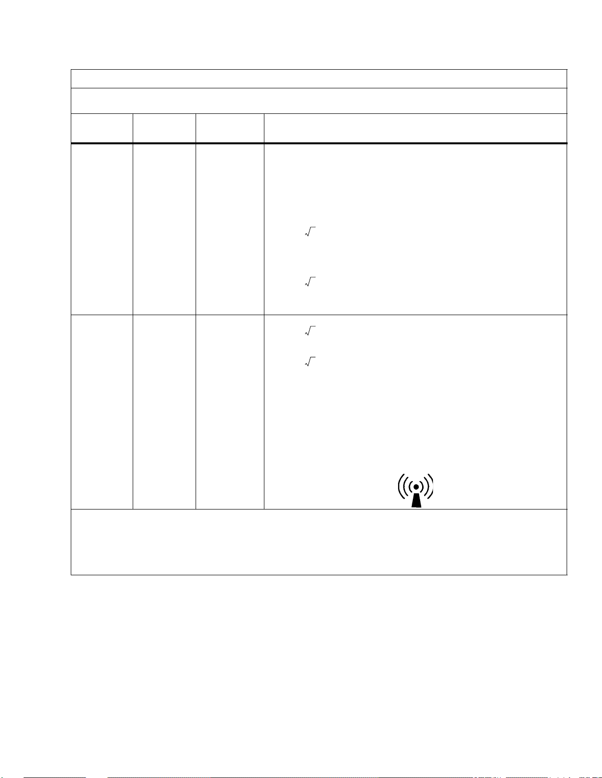
Electromagnetic Compatibility (EMC) Guidance and Manufacturer’s Declarations
Guidance and Manufacturer’s Declaration—Electromagnetic Emissions
The C400 QT® and C450 QT® Air-Shields ® Isolette® Infant Incubator is intended for use in the electromagnetic environment specified below . The customer or user of the unit should ensure that the unit is
used in such an environment.
Emissions Test Compliance Electromagnetic Environment—Guidance
Radio frequency (RF)
emissions—CISPR 11
Group 1 The C400 QT® and C450 QT® Air-Shields ®
Isolette® Infant Incubator uses RF energy only
for its internal function. Therefore, its RF emissions are very low and are not likely to cause
interference with nearby electronic equipment.
RF emissions—CISPR 11Class A The C400 QT® and C450 QT® Air-Shields ®
Isolette® Infant Incubator is suitable for use in
Harmonic Emissions—
IEC 61000-3-2
Voltage fluctuations/
flicker emissions—IEC
Pass
Pass
all establishments other than domestic and those
directly connected to the public lowvoltage power supply network that supplies
buildings used for domestic purposes.
61000-3-4
2 - 11

DRAFT 19 May 2005
Guidance and Manufacturer’s Declaration—Electromagnetic Immunity
The C400 QT® and C450 QT® Air-Shields ® Isolette® Infant Incubator is intended for use in the electromagnetic environment specified below . The customer or user of the unit should ensure that the unit is used in such an
environment.
Immunity Test
IEC 60601 Test
Level
Compliance Level
Electromagnetic Environment—
Guidance
Electrostatic
discharge (ESD)—
IEC 61000-4-2
Electrical fast
transient/burst—IEC
61000-4-4
Surge—IEC 610004-5
Voltage dips, short
interruptions, and
voltage variations on
power supply input
lines—IEC 61000-411
Power frequency
(50/60 Hz)
magnetic field—IEC
61000-4-8
± 6 kV contact
± 8 kV air
± 6 kV contact
± 8 kV air
The floors should be wood, concrete, or
ceramic tile. If floors are covered with
synthetic material, the relative humidity
should be at least 30%.
± 2 kV for power
supply lines
± 1 kV for input/ output lines
± 1 kV
differential mode
± 2 kV common
mode
< 5% U
in U
40% U
U
T
70% U
U
T
< 5% U
in U
(> 95% dip
T
) for 0.5 cycles
T
(60% dip in
T
) for 5 cycles
(30% dip in
T
) for 25 cycles
(> 95% dip
T
) for 5 seconds
T
± 2 kV for power
supply lines
± N/A for input/output lines
± 1 kV
differential mode
± 2 kV common
mode
< 5% U
in U
40% U
U
T
70% U
U
T
< 5% U
in U
(> 95% dip
T
) for 0.5 cycles
T
(60% dip in
T
) for 5 cycles
(30% dip in
T
) for 25 cycles
(> 95% dip
T
) for 5 seconds
T
Mains power quality should be that of a
typical commercial or hospital
environment.
There are no I/O cables for this product.
Mains power quality should be that of a
typical commercial or hospital
environment.
Mains power quality should be that of a
typical commercial or hospital
environment. If the user of the unit
requires continued operation during power
mains interruptions, it is recommended
that the unit be powered from an
uninterruptable power supply or battery.
3 A/m 3 A/m The power frequency magnetic fields
should be at levels characteristic of a
typical location in a typical commercial or
hospital environment.
2 - 12
NOTE:
UT is the AC mains voltage prior to the application of the test level.
DRAFT 19 May 2005
Guidance and Manufacturer’s Declaration—Electromagnetic Immunity
The C400 QT® and C450 QT® Air-Shields ® Isolette® Infant Incubator is intended for use in the electromagnetic envi ronment specified below. The customer or user of the unit should ensure that the unit is used in such an environment.
Immunity
Test
Conducted
RF—IEC
61000-4-6
Radiated
RF—IEC
61000-4-3)
IEC 60601
Test Level
3 Vrms
Compliance
Level
3 Vrms
150 kHz to 80
MHz outside
ISM bands
10 Vrms
a
10 Vrms
150 kHz to 80
MHz in ISM
bands
10 V/m 10 V/m
80 MHz to
2.5 GHz
Electromagnetic Environment—Guidance
Recommended Separation Distance
Portable and mobile RF communication equipment should be used no
closer to any part of the C400 QT® and C450 QT® Air-Shields ® Isolette® Infant Incubator, including cables, than the recommended separation
distance calculated from the equation applicable to the frequency of the
transmitter.
Recommended Separation Distance
d 1.2 P=
d 1.2 P=
d 1.2 P=
d 2.3 P=
where P is the maximum output power rating of the transmitter in watts
(W) according to the transmitter manufacturer and d is the recommended
separation distance in meters (m).
Field strengths from fixed RF transmitters, as determined by an
electromagnetic site survey
each frequency range.
Interference may occur in the vicinity of equipment marked with the following symbol:
80 MHz to 800 MHz
800 MHz to 2.5 GHz
c
, should be less than the compliance level in
d
b
NOTE:
At 80 MHz and 800 MHz, the higher frequency range applies.
NOTE:
These guidelines may not apply in all situations. Electromagnetic propagation is affected by absorption and reflection
from structures, objects, and people.
a. The industrial, scientific, and medical (ISM) bands between 150 kHz and 80 MHz are 6765 MHz to 6795 MHz; 13553 MHz to 13567 MHz; 26957 MHz to 27283 MHz; and 4066 MHz to 4070
MHz.
b. The compliance levels in the ISM bands between 150 kHz and 80 MHz and in the frequency range 80 MHz to 2.5 GHz are intended to decrease the likelihood that mobile/portable
communications equipment could cause interference if it is advertently brought into patient areas. For this reason, an additional factor of 10/3 is used in calculating the recommended
separation distance for transmitters in these frequency ranges.
c. Field strengths from fixed transmitters, such as base stations for radio, cellular/cordless telephones, land-mobile radios, amateur radio, AM and FM radio broadcast, and TV broadcast cannot be
predicted theoretically with accuracy. To assess the electromagnetic environment due to fixed-RF transmitters, an electromagnetic site survey should be considered. If the measured field
strength in the location in which the unit is used exceeds the applicable RF compliance level, observe the unit to verify normal operation. If abnormal performance is observed, additional
measures may be necessary, such as reorienting or relocating the unit.
d. Over the frequency range 150 kHz to 80 MHz, field strengths should be < 3 V/m.
2 - 13
DRAFT 19 May 2005
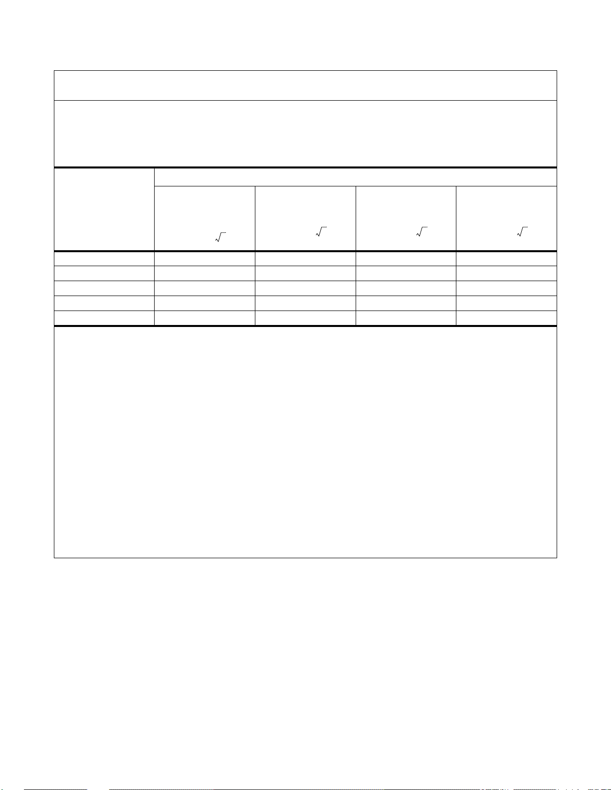
Recommended Separation Distances Between Portable and Mobile RF Communications
Equipment and the C400 QT® and C450 QT® Air-Shields ® Isolette® Infant Incubator
The C400 QT® and C450 QT® Air-Shields ® Isolette® Infant Incubator is intended for use in the electromagnetic environment in which radiated RF disturbances are controlled. The customer or user of the unit can help
prevent electromagnetic interference (EMI) by maintaining a minimum distance between portable and mobile RF
communications equipment (transmitters) and the unit as recommended, according to the maximum output power
of the communications equipment.
Separation Distance According to the Frequency of the Transmitter (m)
Rated Maximum
Output Power of
the Transmitter
(W)
0.01 W 0.12 m 0.12 m 0.12 m 0.23 m
0.1 W 0.38 m 0.38 m 0.38 m 0.73 m
1 W 1.2 m 1.2 m 1.2 m 2.3 m
10 W 3.8 m 3.8 m 3.8 m 7.3 m
100 W 12 m 12 m 12 m 23 m
For transmitters rated at a maximum output not listed above, the recommended separation distance (d)
in meters (m) can be determined using the equation applicable to the frequency of the transmitter , where
P is the maximum output power rating of the transmitter in watts (W), according to the transmitter’s
manufacturer.
NOTE:
At 80 MHz and 800 MHz, the higher frequency range applies.
NOTE:
The industrial, scientific, and medical (ISM) bands between 150 kHz and 80 MHz are 6765 MHz to 6795
MHz; 13553 MHz to 13567 MHz; 26957 MHz to 27283 MHz; and 4066 MHz to 4070 MHz.
NOTE:
An additional factor of 10/3 is used in calculating the recommended separation distance for transmitters in the
ISM frequency bands between 150 kHz and 80 MHz and in the frequency range 80 MHz to 2.5 GHz to
decrease the likelihood that mobile/portable communications equipment could cause interference if it is
inadvertently brought into patient areas.
NOTE:
These guidelines may not apply in all situations. Electromagnetic propagation is affected by absorption and
reflection from structures, objects, and people.
150 kHz to
80 MHz Outside
ISM Bands
d 1.2 P=
150kHz to 80 MHz
in ISM Bands
d 1.2 P= d 1.2 P= d 2.3 P=
80 MHz to
800 MHz
800 MHz to
2.5 GHz
2 - 14
 Loading...