

Page 1
5695031
Edition 04 – January 2019 (Edition 01 – March 2014)
en
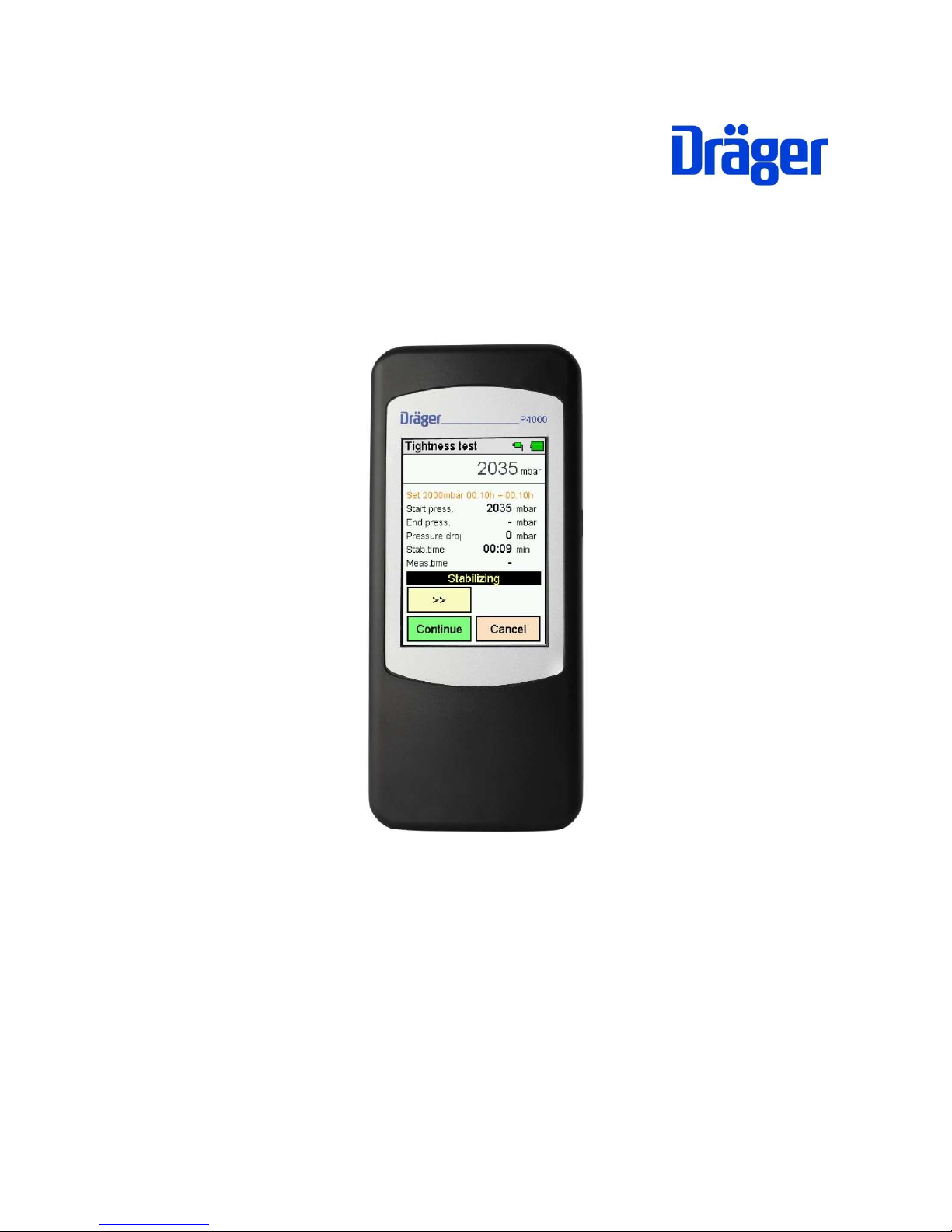
Instruction manual P4000
Dräger MSI GmbH
Rohrstraße 32
D - 58093 Hagen
Tel.: 0049 - 2331 / 9584 - 0
Fax: 0049 - 2331 / 9584 - 29
e-mail: info@draeger-msi.de
Page 2

Instruction manual Dräger P4000
1
Inhalt
1. Information ....................................................................................................................... 3
1.1 Warning signs ............................................................................................................. 3
1.2 For your safety ............................................................................................................ 3
1.3 Safety instructions and warnings ................................................................................ 4
1.4 Bluetooth ..................................................................................................................... 4
1.5 Disclaimer ................................................................................................................... 5
1.6 Maintenance and servicing ......................................................................................... 5
1.7 Disposal ...................................................................................................................... 5
2. Application ....................................................................................................................... 6
3. The instrument ................................................................................................................. 7
4. Operation of the instrument ............................................................................................. 8
4.1 General ....................................................................................................................... 8
4.2 Switch ON / OFF ......................................................................................................... 8
4.3 Buttons ........................................................................................................................ 9
4.4 Input .......................................................................................................................... 10
4.5 Integrated instruction manual .................................................................................... 10
4.6 Start a measurement ................................................................................................ 11
4.7 Result display............................................................................................................ 11
4.8 Documentation menu ................................................................................................ 11
5. Main menu ..................................................................................................................... 12
6. Auswahl und Eingabe von Kundendaten ....................................................................... 12
7. Pressure measurements ................................................................................................ 13
8. Performance of tightness and stress tests ..................................................................... 14
9. General tightness test .................................................................................................... 15
10. Gas pipe tests .............................................................................................................. 16
10.1 General Information ................................................................................................ 16
10.2 Selection of gas pipe test ........................................................................................ 16
10.3 Tightness test according to DVGW TRGI 2008 worksheet G 600........................... 16
10.4 Stress test according to DVGW TRGI 2008 worksheet G 600 ................................ 17
10.4.1 Pipings with operating pressures up to and including 100 mbar ....................... 17
10.4.2 Pipings with operating pressures over 100 mbar up to and including 1 bar ...... 18
11. Liquid gas pipe tests .................................................................................................... 19
11.1 General information ................................................................................................ 19
11.2 Auswahl der Flüssiggasleitungsprüfung .................................................................. 19
11.3 Tightness test according to DVFG TRF 2012 ......................................................... 19
11.4 Strength test according to DVFG TRF 2012 ........................................................... 20
12. Water pipe checks ....................................................................................................... 20
12.1 General Information ................................................................................................ 20
12.2 Selection of drinking-water installation test ............................................................. 21
12.3 Tightness test with air ............................................................................................. 21
12.4 Stress test with air up to DN 50 3 bar and up to DN 100 1 bar ............................... 22
12.5 Tightness test with water for crimped connections (untight if not crimped) ............. 22
12.6 Tightness test with water for metal-, multi-layer composite- and PVC pipings ........ 23
12.7 Tightness test with water for PP, PE, PE-X- and PB pipes, and with these combined
pipings ............................................................................................................................ 23
13. Checklists .................................................................................................................... 24
14. Data storage ................................................................................................................ 24
14.1 Store measurements ............................................................................................... 24
14.2 Data storage functions ............................................................................................ 25
Page 3

Instruction manual Dräger P4000
2
14.3 Data storage information ......................................................................................... 25
14.4 Display stored measurements ................................................................................ 25
14.5 Inspector table ........................................................................................................ 26
14.6 Delete measurement data ....................................................................................... 26
15. Device information ....................................................................................................... 27
16. Adjustments ................................................................................................................. 27
16.1 Date and time.......................................................................................................... 27
16.2 Key beep ................................................................................................................. 28
16.3 MSI infrared printer ................................................................................................. 28
16.4 Display lighting ........................................................................................................ 28
16.5 Overlaying of the integrated help function ............................................................... 28
16.6 Automatic daylight saving time................................................................................ 28
16.7 Printer footer text .................................................................................................... 28
16.8 Language ................................................................................................................ 28
17. Warning notes and error messages ............................................................................. 29
18. Power supply ............................................................................................................... 30
18.1 General information about the power supply .......................................................... 30
18.2 Battery charging ...................................................................................................... 30
19. Technical data ............................................................................................................. 31
19.1 General technical data ............................................................................................ 31
19.2 Technical Data Pressure Measurements ................................................................ 31
20. Care and maintenance ................................................................................................. 32
21. Consumables and accessories .................................................................................... 32
22. PC measurement data management ........................................................................... 32
Page 4
Instruction manual Dräger P4000
3
1. Information
The manufacturer of this product, Dräger MSI GmbH, is referred to as Dräger MSI in the
following.
The displays shown in this manual are examples!
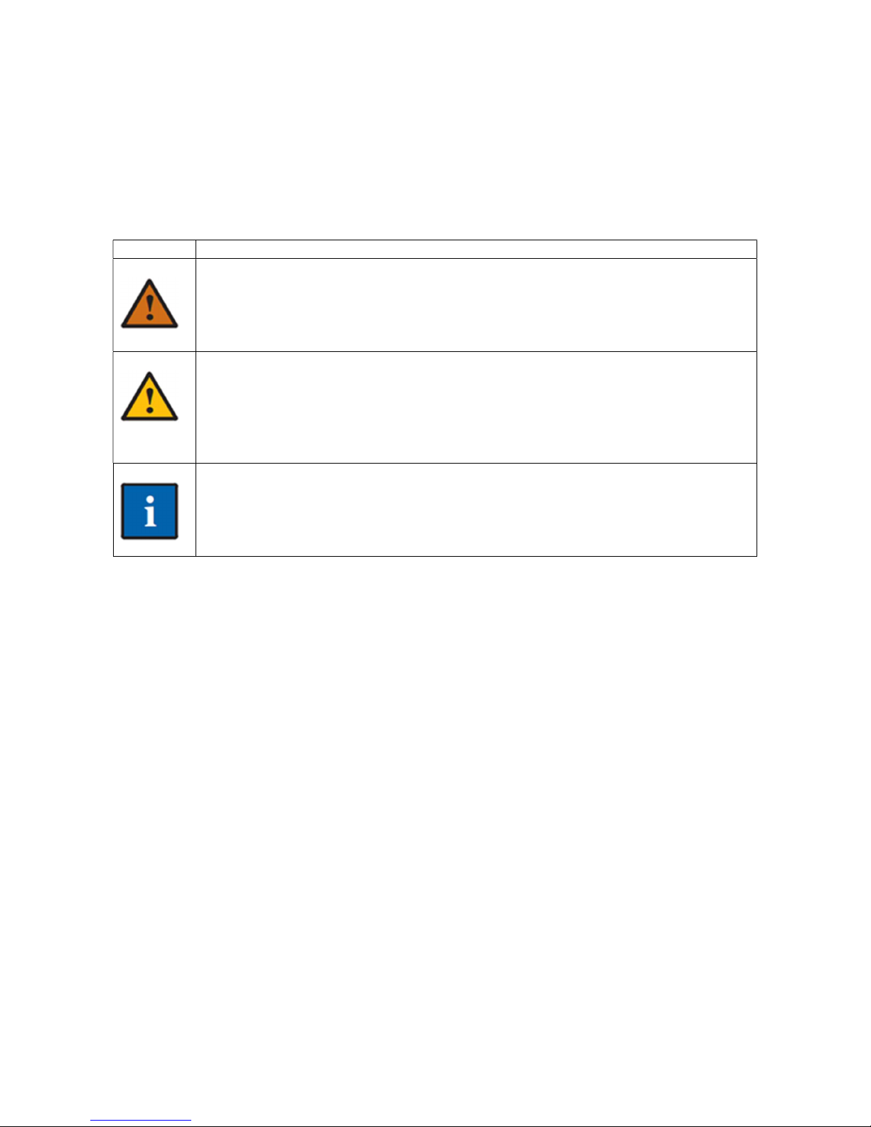
1.1 Warning signs
Symbol Text
Warning
Indication of a potential dangerous situation. Avoiding this warning can lead
to death or severe injuries.
Caution
Indication of a potential dangerous situation. Avoiding this warning can lead
to injuries or damages to the product or the environment. Can also be used
as a warning against improper use.
Information
Additional information regarding the use of the product.
1.2 For your safety
Please read these operating instructions and those for the corresponding products
carefully before using the product.
The operating instructions must be strictly followed. The user must completely under-
stand the instructions and follow them precisely. This product may only be used in
compliance with the designated use.
Do not dispose of the operating instructions. Ensure safekeeping and proper use by
the users.
Only trained and competent personnel are permitted to use this product.
Observe local and national guidelines pertaining to this product.
Maintenance work may only be conducted by Dräger MSI or by qualified personnel
trained by Dräger MSI- Otherwise the responsibility for the proper functioning of the
product after maintenance and for the validity of approvals is rejected by Dräger MSI.
Only use original Dräger parts and accessories for maintenance work. Otherwise the
proper use of the product can be compromised.
Do not use defective or incomplete products. Do not modify the product in any way.
Page 5
Instruction manual Dräger P4000
4
1.3 Safety instructions and warnings
Do not operate the product if there is damage to the housing, power supply or supply
lines. Mark the product, to protect it against further use.
Do not conduct any measurements, which could lead to contact with uninsulated, hot
parts.
Only use the product appropriately and as intended and within the parameters spec-
ified in the technical specifications. The improper use of this product can result in
death, severe injuries or the destruction or damage of the product.
Do not use this product in environments exposed to explosion hazards.
This product is equipped with a magnetic holder. The magnetic field can be hazard-
ous to the health of persons with pacemakers.
Do not open rechargeable batteries or batteries and do not throw them into fire.
Store this product in a place at room temperature without exposure to solvents, plas-
ticizers agents, emissions or combustible materials.
Only use this product in closed and dry rooms. Protect it against rain and moisture.
Independent modifications to the product can lead to malfunctions and are prohibited
for safety reasons. Dräger MSI otherwise refuses the responsibility for the proper
functioning of the product after modification and for the validity of the certifications.
This product is equipped with a magnetic holder. The magnetic field can damage
other products. Keep a safe distance from other products (e.g. mobiles, computers,
monitors, credit cards, memory cards, etc.).
1.4 Bluetooth
Changes or modifications not specifically approved by the responsible admissions
office can lead to the revocation of the operating license. Devices transmitting in the
same ISM radio band, e.g. mobiles, WLAN, microwaves, etc, can destroy data trans-
mission.
Among others, the use of radio communication is prohibited in aircraft and hospitals.
Page 6

Instruction manual Dräger P4000
5
1.5 Disclaimer
Dräger MSI does not assume any liability or warranty for damages or consequential
damage arising from non-compliance with technical regulations, instructions and rec-
ommendations. Dräger MSI and the sales companies are not liable for costs or damages resulting from the use of the product by the user or third parties, especially in the case
of improper use of the product. Neither Dräger MSI nor the sales companies are liable for
the incorrect use of the product.
1.6 Maintenance and servicing
To ensure proper functioning and measurement accuracy, service specialists trained
by the Dräger MSI GmbH should conduct calibration and adjustment annually.
The device can be cleaned with a damp, not wet, cloth. Do not use any chemical
cleaning agents. Please make sure that the device connections are not clogged or dirty.
1.7 Disposal
The EU-wide directives for the disposal of electrical and electronic equipment apply.
Please observe the applicable local environmental regulations for disposal or return
the product to Dräger MSI or your national dealer for disposal. Defective rechargeable batteries are considered hazardous waste and must be brought to the designated collection points for disposal.
Page 7
Instruction manual Dräger P4000
6
2. Application
The Dräger P4000 is an electronic measuring instrument, to measure pressure at air, gas
or water filled pipings and containers.
It is not suitable for continuous operation or as a safety or alarm device.
All tests and measurements can be documented through print outs or storage.
Every use of a Dräger P4000 requires the exact knowledge and compliance of this
instruction manual, the corresponding norms and standards, the applicable legal
provisions, and the regulations and rules for health and safety at work.
The instrument is only destinated for the applications, as described in this instruction manual.
Before each measurement make sure that the instrument and the accessories are in
a perfect condition. Provisional sealing plugs (rubber plugs) of pressurized pipings
that are used over an operating pressure of 0.5 bar represent an increased safety risk.
Only use a 5 V DC / 1 A USB power supply unit, to always fully charge the Dräger
FG7000 via the USB port. Incomplete charging affects the charging capacity of the
battery in the long run.
The shown display screen shots in this instruction manual are examples!
Pressure tests with water may only be carried out with the external pressure sensor
EP250. The internal pressure sensor and the external pressure sensor EP35 can be
damaged by tests with water.
Page 8
Instruction manual Dräger P4000
7
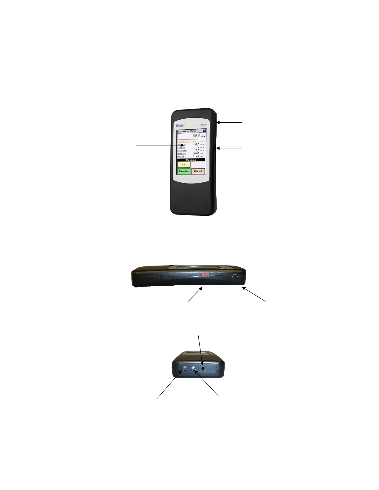
3. The instrument
The Dräger P4000 allows to perform versatile pressure and tightness tests at air, gas or
water filled pipings and containers.
All tests and measurements can be documented by printing them out or by storing them in
the data storage.
USB interface
Illuminated colour display Charge control indicator,
with touchscreen IR transmitter
Interfaces
Charge control indicator + IR transmitter USB interface
External sensor
(-)mbar sensor (+) mbar sensor
Page 9
Instruction manual Dräger P4000
8
4. Operation of the instrument
4.1 General
The Dräger P4000 is operated by a touchscreen display. You can execute the touch and
wipe functions on the screen via your finger or a plastic stylus. Inappropriate are ballpoint
pens, pencils, metal pens and suchlike.
The display is a resistive touchscreen and so you have to apply more pressure to operate
it, than you may know it from modern Smartphones with a capacitive touchscreen.
Menus and lists can be moved upwards and downwards by up and down moving ges-tures
(wiping).
Menus and list positions are marked by tapping. The selected position can be activated by
tapping the 'SELECT' button or by tapping it again.
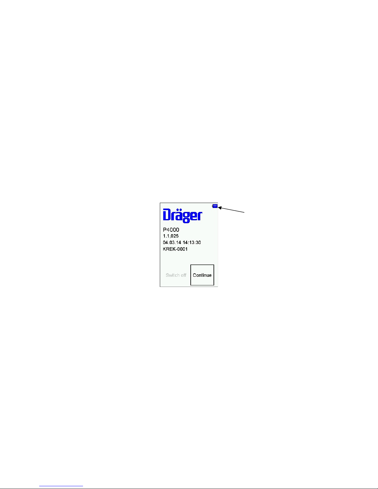
4.2 Switch ON / OFF
Switch ON: Touch the display for 1 second until it is illuminated.
Battery symbol
The start screen displays device type, software version, date and time and the serial number.
The battery symbol indicates the state of charge.
Via tapping the 'OK' button, the main menu will appear. If the button won't be tapped within
5 seconds after switching ON the instrument, it will switch OFF automatically.
Switch OFF: Choose in the main menu 'OFF' or hold the touch screen tapped for at least
5 seconds from any menu option.
Page 10
Instruction manual Dräger P4000
9
4.3 Buttons
Menu = opens a context menu for selection and editing of facility data
Select = activates the marked position
OK = confirms a selection
Ready = continues to the next step after an action
Continue = continues to the next step of a function
Cancel = ends a function, moves to the main menu
>> = scrolls forwards, displays diagram
<< = scrolls backwards, displays statistical data
Zero = adjusts the zero point of the pressure sensor
Start = starts the measurement
Stop = stops the measurement
New = prepares a new measurement
Docu = moves to the documentation menu
Back = moves from the documentation menu to the result display
Customer = moves from the documentation menu to the facility selection
Print = prints out the test result via the IR transmitter
Store = stores the test result in the data storage
End = moves from the documentation menu to the main menu
Finish = ends the measurement time prematurely
Input = opens the editing function for printer texts
Page 11

Instruction manual Dräger P4000
10
4.4 Input
Via the button 'MENU' a context menu opens. In addition to the menu
option the context menu offers various editing functions and commands.
Customer data and comments can be edited via an overlaid keypad.
The penetration of the display with sharp or pointed items can destroy the display.
4.5 Integrated instruction manual
Via the menu function 'Settings' the integrated instruction manual can
be activated. If the integrated instruction manual is activated the particular operation hints will be shown at the start.
With '>>' and '<<' you can scroll between the pages.
Via the 'Continue' button the test will be started.
Page 12

Instruction manual Dräger P4000
11
4.6 Start a measurement
Before the beginning of a test, a connection diagram note will be displayed, that will be used for each particular test.
4.7 Result display
After ending of a test, the results will be displayed.
For pressure and tightness tests the start pressure, the end pressure, the pressure drop and
the measurement time are displayed, for tightness tests additionally the stabilization time.
4.8 Documentation menu
After ending a test the documentation menu can be called up.
If no customer has been selected, before the test, it is possible to select
or create a customer from here.
Via the 'Save' button the test result will be allocated to the particular
customer. If no customer has been selected, the test result will be
stored only with time and date.
Via the 'Print' button the test result can be transmitted to an infrared
printer via the integrated IR transmitter.
Page 13

Instruction manual Dräger P4000
12
5. Main menu
Selectable menu options are:
Switch off: Switch off the instrument
Customer / Facility: Select and edit facility data sets
Pressure: General pressure measurements
General test: Tightness test with free input of measuring parameters
Gas pipes: Gas pipe tests according to DVGW TRGI 2008 G 600
Liquid gas pipes: Liquid gas pipe tests according to TRF 2012
Water pipe test: Water pipe tests according to DIN EN 806
Checklists: Select, edit and store checklists
Data storage: data storage information, measurement data and inspector table
Info: Instrument information
Settings: Edit instrument settings, set clock
6. Auswahl und Eingabe von Kundendaten
Via the PC software it is possible to create customer numbers, customer names and customer data and transfer these data to the instrument.
If customer data are stored in the instrument it is possible to select a
customer and to store measurements to this customer via this function.
Are there no customer data stored they can putted in via this function.
Select: The displayed customer number will be overtaken.
Menu: The context menu opens.
Without: Measurements will be stored without facility allocation.
New: New customer data can be created.
Search: A character string can be searched for (e.g. a name).
Delete: Selected data set can be deleted. That is only
possible, if there are no measurement data stored in
the instrument.
Page 14

Instruction manual Dräger P4000
13
Via 'Edit' function the marked customer number and corresponding
data, if any, will be displayed.
Via 'Select' these data can be edited and taken over by tapping 'Ready'.
Customer number, name, kind of installation, installation location, installation number, street, post code, city, customer name, customer
street, customer post code, customer city and customer phone number
can be typed in.
The overtaken customer number is valid for all following tests, as long
as the instrument is switched on or another customer number is chosen.
7. Pressure measurements
Connect the test nipple of the pressure container or pressure pipe, that
has to be measured, via a pressure hose to the corresponding pressure
input of the instrument. For the high pressure measurement (3.5 bar /
25 bar) the external sensor (optional) has to be connected.
Selectable functions:
Zero: displayed measurement value will be set to zero
>> / <<: switch between statistical data and diagram
Start: start of the pressure measurement
Cancel: cancels current pressure measurement
After starting the pressure measurement the actual pressure, the start
pressure, the difference to the start pressure and the elapsed duration
are displayed.
After ending of the measurement the results are displayed.
Page 15

Instruction manual Dräger P4000
14
8. Performance of tightness and stress tests
During the test an info text informs about the current progress.
Each tightness and stress test consists of a stabilisation phase for the
temperature compensation, and following measurement. Test pressure
and duration of stabilization phase and measurement depend on the
corresponding norms. (TRGI, TRF, TRWI, …).
At the beginning of a tightness or stress test, the particular test pressure
has to be applied.
If the test pressure has been applied, or the pressurization has been
stopped prematurely, the stabilization phase starts with 'Ready'.
During the stabilization phase the actual pressure, the start pressure of
the stabilization phase, the pressure drop and the elapsed stabilization
time are displayed.
A negative pressure drop (e.g. -0.1 mbar) means an increase in pressure. A possible reason for that is influence of temperature.
If the stabilization time has elapsed or the stabilization phase has been
ended prematurely with 'Continue', the measurement starts.
During the measurement the actual pressure, the start pressure of the
measurement, the pressure drop during the measurement, the stabilization time and the elapsed measuring time are displayed.
After the measuring time is elapsed or the measurement has been
ended prematurely, the results are displayed.
The start pressure of the measurement, the end pressure of the measurement, the pressure drop during the measurement, the stabilization
time and the measuring time are displayed.
Page 16

Instruction manual Dräger P4000
15
9. General tightness test
Via this function it is possible to perform tightness tests with freely selectable nominal pressure, stabilization time and measuring time.
For the general tightness test it is possible to adjust the test pressure,
the stabilization time and the measuring time.
The test pressure is adjustable between 20 and 25,000 mbar, the stabilization time and the measuring time is adjustable between 5 minutes
and 6 hours.
Via the selection buttons, behind the displayed values, the input function opens.
The nominal pressure can be putted in freely, the times can be selected from a list.
'Continue' starts the test. During the measurement you can scroll with
'>> / <<' anytime between the table and diagram display.
Pressurization: In this phase the instrument waits for the increase of
pressure. 'Ready' confirms the achieving of the test pressure.
Stabilization phase: The instrument awaits the given time and switches
automatically to measurement.
The stabilization phase can be ended by tapping 'Continue'.
Measurement: Within the measuring time the pressure history, as start
pressure, end pressure and the differential pressure are monitored.
The given measuring time can be shortened via the 'Ready' button.
Ready: After the measurement the monitored results will be available.
Page 17

Instruction manual Dräger P4000
16
10. Gas pipe tests
10.1 General Information
For the installation and maintenance of gas pipes, a stress test and a tightness test according to DVGW TRGI 2008 worksheet G600 has to be performed.
For new laid pipings a stress test and a tightness test has to be performed, before the pipings
are plastered or covered.
New or existing pipings, which are being worked upon, are only allowed to fill with gas if the
stipulated tests have passed.
For tightness and stress tests pipings, that have to be inspected, have to be discon-
nected from gas-carrying lines and have to be metal-to-metal seated.
The tests have to be performed with air or inert gas (e.g. Nitrogen)
10.2 Selection of gas pipe test
Selectable functions:
Tightness test: Tightness test at 150 mbar
Stress test 1 bar: Stress test at 1 bar
Stress test 3 bar: Stress test at 3 bar
10.3 Tightness test according to DVGW TRGI 2008 worksheet G 600
A tightness test has to be performed and documented for every new or significantly modified
installation with operation pressures up to and including 100 mbar.
It surrounds the piping including fittings, though without gas appliances and associated control and safety fittings.
For the tightness test the pressure in the gas pipe, that has to be tested, has to be increased
according to DVGW TRGI 2008 to some more than 150 mbar.
After a stabilisation phase for the temperature balance, the pressure in the pipe, that has to
be tested, will be measured for the stipulated time.
The stabilisation times and test times are defined according to the pipe's volume (pipe section), that has to be tested.
Page 18

Instruction manual Dräger P4000
17
For the determination of the stabilisation time and test time, the volume
of the pipe section, that has to be tested, has to be determined.
Via the selection buttons behind the displayed values, the input function
opens.
Stabilisation time and measuring time at tightness tests according to TRGI G 600
1. Determine measuring time via volume input.
2. Increase pressure in the pipe, that has to be tested, to some more than 150 mbar.
For that connect a pump via a valve to the pipe and increase the pressure.
3. Confirm the pressure increase by tapping 'Ready', the stabilization time starts.
4. After the stabilization time the measurement time starts automatically.
10.4 Stress test according to DVGW TRGI 2008 worksheet G 600
10.4.1 Pipings with operating pressures up to and including 100 mbar
For new gas installations of low-pressure systems (operating pressure ≤ 100 mbar) a stress
test has to be performed, before the tightness test. It surrounds the piping without fittings,
gas control appliances, gas meters gas appliances and associated control and safety fittings.
For the stress test the pressure in the gas pipe has to be increased to 1 bar. After a temperature balance (no specific time is stipulated, 10 minutes are appropriated), the pressure in
the pipe will be measured for 10 minutes.
1. Increase pressure in the pipe, that has to be tested, to some more than 1 bar. For
that connect a pump via a valve to the pipe and increase the pressure.
2. Confirm the pressure increase by tapping 'Ready', the stabilization time starts.
3. After the stabilization time the measurement time starts automatically.
Pressure Volume Stabil. time Meas. time
150 mbar < 100 l 10 min 10 min
150 mbar ≥ 100 l < 200 l 30 min 20 min
150 mbar ≥ 200 l 60 min 30 min
Page 19

Instruction manual Dräger P4000
18
10.4.2 Pipings with operating pressures over 100 mbar up to and including 1 bar
For pipings of new middle-pressure systems (operating pressure 100 mbar up to 1 bar) a
combined stress test and tightness test has to be performed. It surrounds the piping including fittings, though without gas control appliances, gas meters, gas appliances and associated control and safety fittings, as far as they are not designed for that test pressure.
For the combined stress test and tightness test the pressure in the gas pipe has to be increased up to 3 bar.
After a temperature balance (3 hours) the pressure in the pipe is measured for 2 hours.
For a pipe volume over 2,000 liters, the test time has to be increased for 15 minutes each
additional 100 liters pipe volume.
For the determination of the measurement time, the volume of the gas
pipe has to be determined.
Via the selection buttons, behind the displayed values, the input function opens.
1. Determine measuring time via volume input.
2. Increase pressure in pipe, that has to be tested, to 3 bar. For that connect a pump
via a valve to the pipe and increase the pressure.
3. Confirm the pressure increase by tapping 'Ready', the stabilisation time starts.
4. After the stabilisation time the measurement time starts automatically.
Page 20

Instruction manual Dräger P4000
19
11. Liquid gas pipe tests
11.1 General information
Liquid gas pipes have to be checked by experts, qualified persons and / or by specialized
companies for a proper condition:
- before the first start-up,
- after modifications,
- after an interruption of operation for more than one year,
- recurring.
Filling of a stationary liquid gas container is regarded as first start-up.
Stipulated tests are: strength test and tightness test
11.2 Auswahl der Flüssiggasleitungsprüfung
Wählbare Prüfungen sind:
Dichtheitsprüfung: Dichtheitsprüfung bei 150 mbar
Festigkeit frei: Festigkeitsprüfung 1 bar an freiliegenden Flüssiggasleitungen
Festigkeit erdgedeckt: Festigkeitsprüfung 1 bar an teilweise erdgedeckten
Flüssiggasleitungen
11.3 Tightness test according to DVFG TRF 2012
Immediately before the start-up all pipes (up to the adjustment elements) have to be tested
for tightness with air and an overpressure of 150 mbar.
Pipes are regarded as tight, when after a temperature balance of 10 minutes the test pressure does not drop within the following test duration of 10 minutes.
1. Increase pressure in liquid gas pipe that has to be tested, to some more than 150
mbar. For that connect a pump via a valve to the liquid gas pipe and increase the
pressure.
2. Remove the pump and confirm the pressure increase by tapping 'Ready', the stabilization time starts.
3. After the stabilization time the measurement time starts automatically.
Page 21

Instruction manual Dräger P4000
20
11.4 Strength test according to DVFG TRF 2012
The strength test can be performed sectional. Apply the 1.1-fold value of the permissible
operating pressure with air or nitrogen, at least the pressure has to be 1 bar.
At exposed pipes a balancing time of 10 minutes is necessary, at partially earth-covered
pipes a balancing time of 30 minutes is necessary.
Read off the pressure from gauge (measurement accuracy 1% of measuring range final
value). Check the gauge for pressure drop earliest after additional 10 minutes.
1. Select strength test 1 bar exposed or 1 bar earth-covered.
2. Increase pressure in gas pipe, that has to be tested, to some more than 1 bar. For
that connect a pump via a valve to the liquid gas pipe and increase the pressure.
3. Remove the pump and confirm the pressure increase by tapping 'Ready', the stabilization time starts.
4. After the stabilization time the measurement time starts automatically.
12. Water pipe checks
12.1 General Information
According to DIN EN 806-4 water pipes have to be pressure tested after new installations,
modification and repair. Demanded is a hygienically proper tightness test. The stipulated
tests can be performed with water, oil-free clean air or inert gas.
The tightness test with inert gas (e.g. Nitrogen) has to be performed where increased hygienic requirements, e.g. in hospitals, retirement homes, kindergartens or medical practices.
The tightness test with air has to be performed, when a prolonged downtime period is expected.
The tightness test with drinking water can be performed, when the water exchange starts up
according to its dedicated operation latest 72 hours after the tightness test.
Tests of drinking-water installations may only be performed via the optional external
high-pressure sensor EP250. If these tests were performed via the internal pressure
sensor or with the external high-pressure sensor EP35, the instrument can be seri-
ously damaged!
Page 22

Instruction manual Dräger P4000
21
12.2 Selection of drinking-water installation test
Selectable functions are:
Tightness air: Tightness test with air 150 mbar
Stress test air 1 bar: Stress test with air 1 bar up to DN 100
Stress test air 3 bar: Stress test with air 3 bar up to DN 50
Tightness crimp: Tightness test with water 6 bar for (untight if not crimped)
crimp connections
Tightness metal, PVC: Tightness test with water 11 bar for metal, multi-layer composite
and PVC pipes
Tightness plastic: Tightness test with water 11 bar for PP, PE, PE-X- and
PB pipes and with these combined pipings
12.3 Tightness test with air
The tightness test of drinking-water installations has to be performed before the stress test.
For the tightness test the pressure in the gas pipe, that has to be tested, has to be increased
to some more than 150 mbar.
After an appropriated stabilisation phase, the pressure in the pipe will be measured within
the stipulated time. The measuring time is determined according to the pipe's volume.
For the determination of the measurement time, the volume of the pipe
section, that has to be tested, has to be determined.
Via the selection buttons, behind the displayed values, the input function opens.
For the measurement up to 100 l pipe volume, a test time of 120
minutes is stipulated. For each additional 100 l pipe volume the test
time has to be increased for 20 minutes.
The duration of the stabilization phase shall be adequate.
A duration of 10 minutes is empirically appropriate.
The measuring time will be calculated automatically in dependence to the pipe volume.
1. Determine measuring time via volume input.
2. Increase pressure in pipe that has to be tested, to some more than 150 mbar. For
that connect a pump via a valve to the pipe and increase the pressure.
3. Confirm the pressure increase by tapping 'Ready', the stabilization time starts.
4. After the stabilization time the measurement time starts automatically
Page 23

Instruction manual Dräger P4000
22
12.4 Stress test with air up to DN 50 3 bar and up to DN 100 1 bar
The stress test of drinking-water installations has to be performed after the tightness test, in
combination with a visual inspection of all pipe connections.
The measuring pressure for nominal diameters up to DN 50 is maximally 3 bar, and for
nominal diameters up to DN 100 maximally 1 bar.
The test time is stipulated with 10 minutes. The duration of the stabilization phase shall be
adequate. A duration of 10 minutes is empirically appropriate.
For safety reasons higher pressures than 3 bar are not permitted for tests with air.
1. Select stress test 1 bar (up to DN 100) or 3 bar (up to DN 50).
2. Increase pressure in pipe to test pressure. For that connect a pump via a valve to the
drinking-water installation and increase the pressure.
3. Remove the pump and confirm the pressure increase by tapping 'Ready', the stabilization time starts.
4. After the stabilization time the measurement time starts automatically.
12.5 Tightness test with water for crimped connections (untight if not crimped)
Untight if not crimped connections have to be tested with a test pressure of 6 bar, or according to their manufacturer’s specifications, before the actual tightness test.
The stabilization time is 10 minutes and the test time is 15 minutes. During the test time a
pressure drop shall not occur, and no leak shall be detectable.
1. Increase pressure in pipe to test pressure. For that connect a pump via a valve to the
drinking-water installation and increase the pressure.
2. Confirm the pressure increase by tapping 'Ready', the stabilization time starts.
3. After the stabilization time the measurement time starts automatically.
Page 24

Instruction manual Dräger P4000
23
12.6 Tightness test with water for metal-, multi-layer composite- and PVC pipings
Drinking-water installations of metal-, multi-layer composite- and PVC pipings have to be
tightness tested with water, at a test pressure of 11 bar.
The stabilization time is 10 minutes and the test time is 30 minutes. During the test time a
pressure drop shall not occur and no leak shall be detectable.
1. Increase pressure in pipe that has to be tested, to 11 bar. For that connect a pump
via a valve to the drinking-water installation and increase the pressure.
2. Confirm the pressure increase by tapping 'Ready', the stabilization time starts.
3. After the stabilization time the measurement time starts automatically.
12.7 Tightness test with water for PP, PE, PE-X- and PB pipes, and with
these combined pipings
The tightness test with water for PP, PE, PE-X- and PB pipes, and with these combined
installations made of metal and multi-layer composite pipings, consists of a stabilization
phase and a measuring phase.
The stabilization time is 30 minutes, the test pressure is for that test 11.0 bar.
During these 30 minutes the test pressure has to be kept up by re-pumping.
After that the test pressure has to be decreased to 5.5 bar. With the decreased pressure a
test time of 120 minutes has to be kept. During the test time a pressure drop shall not occur
and no leak shall be detectable.
1. Increase pressure in pipe that has to be tested, to 11.0 bar. For that connect a pump
via a valve to the drinking-water installation and increase the pressure.
2. Confirm the pressure increase by tapping 'Ready', the stabilization time starts.
3. Keep up the test pressure within the 30 minutes of the stabilization phase by repumping.
4. Decrease after the stabilization time the test pressure to 5.5 bar and start the measuring time.
Page 25

Instruction manual Dräger P4000
24
13. Checklists
Measurement regulations often contain visual and other inspections that have no context to
the actual test. The checklists offer a possibility to gather such additional information for
these tests or facilities. In addition, work instructions can be created and worked through.
With the PC software it is possible to configure up to 4 checklists with each up to 20 checkpoints. Each checkpoint can be configured that an answering with Yes / No, or with a max.
5 character long input is possible.
If no input is done yet, the value will be displayed with ---.
14. Data storage
14.1 Store measurements
If no facility number has been selected, before the measurement, a facility can be allocated, before storing the result, with 'Customer' in the
documentation menu.
Without a facility allocation the measurement will be stored with time
and date.
With a facility allocation additionally a facility number will be displayed.
Page 26

Instruction manual Dräger P4000
25
14.2 Data storage functions
Selectable functions are:
Info: Data storage information
Show data: Display data set
Inspector table: Select and edit inspector table
Delete measurements: Delete all measurement data storage
14.3 Data storage information
In the data storage information the number of stored customers, stored
measurements and the total number of used storage spaces are displayed.
14.4 Display stored measurements
Measurements are stored with date, time and facility number -if allocated- .
'Select' calls up the result display of a measurement.
Page 27

Instruction manual Dräger P4000
26
'Docu' displays the allocated facility, and the measurement result can
be printed out with facility and inspector.
14.5 Inspector table
The inspector table contains inspectors with inspector number, street,
postcode, city and telephone number.
The selected inspector will be allocated with the stored measurement
data set.
An inspector can only be deleted if no measurement data is stored in
the instrument.
14.6 Delete measurement data
Delete measurement data: All stored measurements will be deleted.
Page 28

Instruction manual Dräger P4000
27
15. Device information
This function informs about the manufacturer (Dräger), instrument type
(P4000), version of the instrument software (1.0,25), the serial number
of the instrument, the set date, the set time and the identification number of the connected external sensor.
Without external sensor a dash is displayed.
16. Adjustments
The instrument can be configured to the users requirements.
Via the buttons, the functions will be enabled or disabled, or switched
to input.
Via '>>' the input of an IR printer footer text will be called up.
16.1 Date and time
Adjustment and change of date and time.
Page 29

Instruction manual Dräger P4000
28
16.2 Key beep
Via that function you can activate or deactivate the key beep.
16.3 MSI infrared printer
Via this function you can choose between printer protocols for MSI printers or HP printers.
Printer MSI IR3: The data transfer and the print outs are faster than those of the HP protocol
compatible printers.
Printer HP: The data transfer complies to the HP protocol and is usable for all HP protocol
compatible printers, of course also for the MSI IR3.
16.4 Display lighting
Via that function the display brightness can be set to 50%, 75% or 100%. The display brightness influences the run time of the battery.
16.5 Overlaying of the integrated help function
Via that function the integrated help function can be activated or deactivated.
16.6 Automatic daylight saving time
Via that function the automatic daylight saving time can be enabled or disabled.
16.7 Printer footer text
Via that function it is possible to put in and edit the footer text for infrared printers on print outs.
16.8 Language
Select country specific language setting.
Page 30

Instruction manual Dräger P4000
29
17. Warning notes and error messages
During the start-up phase and while measurements, the instrument monitors its proper function. Warning notes and error messages will be displayed after the start-up or during the
regular use.
Clock not set
Date and time has to be set, e.g. after deep discharge of the battery.
Charge level
The battery has to be charged.
Settings
Check settings and change them if necessary.
Printer footer text
An error in the printer footer text has occurred. Put in the printer footer text or transfer it from
PC.
Data storage
Confirm the prompt request 'Reinitialise data storage?'. The whole data storage will be deleted!
Calibration
An error in the calibration has occurred. Give instrument to your nearest service partner.
Options
An error in the options has occurred. Give instrument to your nearest service partner.
Page 31

Instruction manual Dräger P4000
30
18. Power supply
18.1 General information about the power supply
A built-in lithium-ion battery allows a mains independent use.
The run time with a fully charged battery is up to 10 hours, but depends to kind of measurement and display lighting.
Measurements can be proceeded during charging.
18.2 Battery charging
The charge level is permanently monitored and displayed by the instrument.
The battery symbol on the display indicates the charge level. Red flashing of the charge
control indicator on the side of the instrument indicates a discharged battery.
The instrument should be charged from this moment. Charge the Dräger P4000 only with
an USB power supply with 5V DC / 1 A. If the instrument will not be used for a longer time,
we recommend a monthly charging for at least 8 hours. The included USB power supply is
designed for a mains voltage of 100 – 240 Volts AC. For safety reasons the proper condition
of the USB power supply should be checked regularly.
The charging takes, depending on its charge level, 1 to 4 hours. During the charging, the
LED of the charge control indicator, on the instrument's side, is flashing red. After the end
of charging, the flashing of the LED turns into a steady light. That means that the battery is
from now on charged with a trickle charge.
If charging has been forgotten, the instrument switches off automatically. If it is impossible
to switch on the instrument, because of low voltage, plug in the charger and switch on the
instrument again!!
Avoid a deep discharge, because that can shorten the lifetime of the battery.
Page 32

Instruction manual Dräger P4000
31
19. Technical data
19.1 General technical data
Display: Colour display with touchscreen
Interfaces: USB, IR
Power supply : Li-ion Battery, 4.8 V, 1500 mAh, charge level indicator
power supply primary 100 - 240 VAC; secondary 5 VDC; 1 A
PC connection/
Charging cable: USB cable max. 1.8 m
Dimensions: 75 x 170 x 27 mm (W x H x D)
Weight: ca. 217 g
Operating temperature: + 5 °C ... + 40 °C
Storage temperature: - 20 °C ... + 50 °C
Humidity: 10 - 90 % RH, non-condensing
Atmospheric pressure: 800 to 1100 hPa
19.2 Technical Data Pressure Measurements
Display Measuring range Resolution Accuracy Max. over pressure
Medium pressure I - 10 … + 100 mbar 0.01 mbar < ± 0.5 mbar or
< ± 1 % f. MV*
750 mbar
Medium pressure II - 10 … + 160 mbar 0.1 mbar < ± 5 % f. MV* 750 mbar
Pressure
(ext. sensor, option)
- 100 … + 3,500 mbar 1 mbar < 1 % f. MR** 4,000 mbar
High pressure
(ext.Sensor, Option)
0.1 … + 25.00 bar 0.01 bar < 1 % f. MR** 35 bar
*MV = Measurement value
**MR = Measuring range
Page 33

Instruction manual Dräger P4000
32
20. Care and maintenance
The instrument shall be given to an authorized service partner annually, where it can be
maintained and recalibrated if necessary, and to keep up the precision of measurements
and a safe function.
The instrument can be cleaned with a damp cloth. Make sure that the instrument's connectors are not clogged or soiled.
21. Consumables and accessories
5600876 Pump adapter 150 mbar with quick connector and Schrader valve
to connect a pump
required is also the ½“ adapter or the single pipe cover
5600875 Pressure sensor EP35 3.5 bar with quick connector and Schrader valve
with a possibility to connect a pump
required is also the ½“ adapter or the single pipe cover
5600877 Pressure sensor EP250 25 bar with quick connector
required is also the ½“ adapter or the single pipe cover
to pressurize up to 10 bar with air additionally the pump adapter 10 bar is
required
5600882 Pump adapter 10 bar with quick connector and Schrader valve
required is also the ½“ adapter or the single pipe cover
5600813 ½“ adapter with quick connector
5600842 Single pipe cover (≤ 3.5 bar) with quick connector
5610709 Gas pressure hose P4000
5600401 Printer IR3 with infrared data transmission
5690151 Printing paper for printer
5600880 Hand pump
5600881 Equipment case P4000
22. PC measurement data management
At our web site www.draeger-msi.de you can find, under the tab Download, the PC driver
for your instrument.
Please register your instrument together with its serial number - to get the download link for
the measurement data management software, click on Service → product registration.
 Loading...