

Page 1
Instructions for Use
Oxylog 3000 plus
WARNING
To properly use this medical device,
read and comply with these
Instructions for Use.
Emergency and Transport Ventilator
Software 1.n
Page 2

Typographical Conventions
1 Consecutive numbers indicate steps of action,
with the numbering restarting with "1" for each
new sequence of actions.
z Bullet points indicate individual actions or differ-
ent options for action.
– Dashes indicate the listing of data, options, or
objects.
(A) Letters in parentheses refer to elements in the
related illustration.
A Letters in illustrations denote elements referred
to in the text.
Any text shown on the screen and any labeling on
the device are printed in bold and italics, for example, PEEP, Air, or Alarm settings.
Trademarks
– Oxylog
– AutoFlow
– DrägerService
are trademarks owned by Dräger.
– Sekusept
is a trademark of ECOLAB.
– BIPAP*
®
®
®
®
The "greater than" symbol > indicates the navigation path in a dialog window, for example, System
setup > Monitoring > Basic settings. In this
example, System setup represents the dialog window title, Monitoring represents a horizontally
aligned tab, and Basic settings a vertically aligned
tab.
Screen images
Schematic renderings of screen images are used,
which may differ in appearance or in configuration
from the actual screen images.
* Trademark used under license
2 Instructions for Use Oxylog 3000 plus SW 1.n
Page 3

Safety Information Definitions
WARNING
A WARNING statement provides important
information about a potentially hazardous
situation which, if not avoided, could result in
death or serious injury.
CAUTION
A CAUTION statement provides important
information about a potentially hazardous
situation which, if not avoided, may result in minor
or moderate injury to the user or patient or in
damage to the equipment or other property.
NOTE
A NOTE provides additional information intended
to avoid inconvenience during operation.
Definition of target groups
For this medical device, users, service personnel,
and experts are defined as target groups.
These traget groups must have been instructed in
the use of the medical device and must have the
necessary expertise, training, and knowledge to
use, install, reprocess, maintain or repair the medical device.
Dräger emphasizes that the medical device must
be used, installed, reprocessed, maintained or
repaired exclusively by the defined target groups.
Users
Users are intended operators as defined on
page 14 hereof for the use of the medical device in
accordance with its intended use.
Instructions for Use Oxylog 3000 plus SW 1.n 3
Service Personnel
Service Personnel are persons who are responsible for the maintenance of the medical device
towards the operating organization.
Service Personnel are persons who are authorized
to install, reprocess, or maintain the medical
device.
Experts
Experts are persons who are authorized to carry
out repair or complex maintenance work on the
medical device.
Page 4

Abbreviations and Symbols
Please refer to "Abbreviations" on page 23 and
"Symbols" on page 24 for explanations.
4 Instructions for Use Oxylog 3000 plus SW 1.n
Page 5

Contents
Contents
For Your Safety and that of Your Patients .7
General Safety Information. . . . . . . . . . . . . . . 8
Product-specific Safety Information . . . . . . . . 11
Application . . . . . . . . . . . . . . . . . . . . . . . . . . 13
Intended use. . . . . . . . . . . . . . . . . . . . . . . . . . 14
Indications / Contraindications . . . . . . . . . . . . 14
Environment of use. . . . . . . . . . . . . . . . . . . . . 15
System Overview . . . . . . . . . . . . . . . . . . . . . 17
Front panel with all options. . . . . . . . . . . . . . . 18
Range of functions . . . . . . . . . . . . . . . . . . . . . 22
Abbreviations . . . . . . . . . . . . . . . . . . . . . . . . . 23
Symbols . . . . . . . . . . . . . . . . . . . . . . . . . . . . . 24
Operating Concept . . . . . . . . . . . . . . . . . . . . 27
Switch on or off. . . . . . . . . . . . . . . . . . . . . . . . 28
Ventilation controls . . . . . . . . . . . . . . . . . . . . . 29
Display operating controls . . . . . . . . . . . . . . . 30
Additional function keys . . . . . . . . . . . . . . . . . 31
Screen window structure . . . . . . . . . . . . . . . . 32
Assembly. . . . . . . . . . . . . . . . . . . . . . . . . . . . 35
Internal rechargeable battery . . . . . . . . . . . . . 37
Connecting the power supply . . . . . . . . . . . . . 38
External power supply . . . . . . . . . . . . . . . . . . 39
Connecting the gas supply . . . . . . . . . . . . . . . 41
Assembling the adult reusable hose system . 43
Connecting the adult disposable hose system 45
Connecting the paediatric disposable hose
system . . . . . . . . . . . . . . . . . . . . . . . . . . . . . . 46
Connecting the bacterial filter or HME . . . . . . 47
Connecting the CO
2 sensor and the cuvette . 48
Hanging the Oxylog 3000 plus on standard
rail systems. . . . . . . . . . . . . . . . . . . . . . . . . . . 49
Getting Started . . . . . . . . . . . . . . . . . . . . . . . 51
Charging the battery. . . . . . . . . . . . . . . . . . . . 52
Determining the approximate pneumatic
operating time. . . . . . . . . . . . . . . . . . . . . . . . . 53
Checking readiness for operation. . . . . . . . . . 54
2 zero calibration and filter check before
CO
ventilation (optional) . . . . . . . . . . . . . . . . . . . . 58
Preparation for use after system check, CO
2
zero calibration and filter check. . . . . . . . . . . 60
Operation . . . . . . . . . . . . . . . . . . . . . . . . . . . 61
Starting operation . . . . . . . . . . . . . . . . . . . . . 62
Preparing ventilation mode . . . . . . . . . . . . . . 64
VC-CMV, VC-AC . . . . . . . . . . . . . . . . . . . . . . 65
VC-SIMV, VC-SIMV/PS. . . . . . . . . . . . . . . . . 68
PC-BIPAP, PC-BIPAP/PS . . . . . . . . . . . . . . . 71
SpnCPAP, SpnCPAP/PS . . . . . . . . . . . . . . . . 73
NIV – Non-invasive ventilation (Mask
ventilation) . . . . . . . . . . . . . . . . . . . . . . . . . . . 76
Special functions . . . . . . . . . . . . . . . . . . . . . . 77
O2 concentration with "O2 blending". . . . . . . 79
Setting HME correction . . . . . . . . . . . . . . . . . 80
Calibration . . . . . . . . . . . . . . . . . . . . . . . . . . . 81
Screen brightness . . . . . . . . . . . . . . . . . . . . . 81
Alarm volume . . . . . . . . . . . . . . . . . . . . . . . . 81
Shutdown . . . . . . . . . . . . . . . . . . . . . . . . . . . 82
Alarms . . . . . . . . . . . . . . . . . . . . . . . . . . . . . 83
Types of alarms. . . . . . . . . . . . . . . . . . . . . . . 84
In the event of an alarm. . . . . . . . . . . . . . . . . 85
Setting alarm limits . . . . . . . . . . . . . . . . . . . . 87
Monitoring . . . . . . . . . . . . . . . . . . . . . . . . . . 89
Displaying curves . . . . . . . . . . . . . . . . . . . . . 90
Displaying measured values . . . . . . . . . . . . . 90
2 measurement (optional) . . . . . . . . . . . . 91
CO
Configuration. . . . . . . . . . . . . . . . . . . . . . . . 95
Setting configuration parameters / display
information. . . . . . . . . . . . . . . . . . . . . . . . . . . 96
Displaying configuration and information . . . 97
Customer Service Mode . . . . . . . . . . . . . . . . 98
Customer service manual . . . . . . . . . . . . . . . 110
Problem Solving . . . . . . . . . . . . . . . . . . . . . 111
Alarm - Cause - Remedy. . . . . . . . . . . . . . . . 112
Messages in the alarm window . . . . . . . . . . . 112
Messages in the information window . . . . . . 120
Error messages during the device check . . . 122
Instructions for Use Oxylog 3000 plus SW 1.n 5
Page 6

Contents
Cleaning, Disinfection and Sterilization . . . 123
Disassembly . . . . . . . . . . . . . . . . . . . . . . . . . . 124
Safety Information on reprocessing . . . . . . . . 127
Reprocessing procedure . . . . . . . . . . . . . . . . 127
Reprocessing list . . . . . . . . . . . . . . . . . . . . . . 131
Assembling parts . . . . . . . . . . . . . . . . . . . . . . 131
Maintenance . . . . . . . . . . . . . . . . . . . . . . . . . 133
Maintenance intervals of Oxylog 3000 plus . . 134
Safety inspections . . . . . . . . . . . . . . . . . . . . . 135
Exchanging the internal battery . . . . . . . . . . . 136
In case of ventilator failure . . . . . . . . . . . . . . . 136
Disposal . . . . . . . . . . . . . . . . . . . . . . . . . . . . 137
Disposing of the medical device. . . . . . . . . . . 138
Disposal instructions . . . . . . . . . . . . . . . . . . . 138
Technical Data . . . . . . . . . . . . . . . . . . . . . . . 139
Ambient conditions . . . . . . . . . . . . . . . . . . . . . 140
Settings . . . . . . . . . . . . . . . . . . . . . . . . . . . . . 141
Performance data. . . . . . . . . . . . . . . . . . . . . . 143
Measured values and curves display . . . . . . . 144
Monitoring. . . . . . . . . . . . . . . . . . . . . . . . . . . . 145
Operating data . . . . . . . . . . . . . . . . . . . . . . . . 146
Device specifications . . . . . . . . . . . . . . . . . . . 149
Materials used . . . . . . . . . . . . . . . . . . . . . . . . 150
Technical Documentation for the
Oxylog 3000 plus according to EMC
standard IEC 60601-1-2 . . . . . . . . . . . . . . . . . 152
Principles of Operation . . . . . . . . . . . . . . . . 157
Ventilation modes. . . . . . . . . . . . . . . . . . . . . . 158
AutoFlow . . . . . . . . . . . . . . . . . . . . . . . . . . . . 162
Dead space . . . . . . . . . . . . . . . . . . . . . . . . . . 164
Determining the cycle time, inspiratory time
and expiratory time. . . . . . . . . . . . . . . . . . . . . 164
Functional description . . . . . . . . . . . . . . . . . . 165
List of Accessories . . . . . . . . . . . . . . . . . . . 167
Index . . . . . . . . . . . . . . . . . . . . . . . . . . . . . . . 169
6
Instructions for Use Oxylog 3000 plus SW 1.n
Page 7

For Your Safety and that of Your Patients
For Your Safety and that of Your Patients
General Safety Information . . . . . . . . . . . . . 8
Strictly follow these Instructions for Use. . . . . 8
Maintenance. . . . . . . . . . . . . . . . . . . . . . . . . . 8
Accessories . . . . . . . . . . . . . . . . . . . . . . . . . . 8
Connected Devices . . . . . . . . . . . . . . . . . . . . 9
Safe connection with other electrical
equipment. . . . . . . . . . . . . . . . . . . . . . . . . . . . 9
Modifications. . . . . . . . . . . . . . . . . . . . . . . . . . 9
Patient safety . . . . . . . . . . . . . . . . . . . . . . . . . 9
Patient monitoring. . . . . . . . . . . . . . . . . . . . . . 9
Information on Electromagnetic Compatibility 9
Functional safety . . . . . . . . . . . . . . . . . . . . . . 10
Appropriate monitoring . . . . . . . . . . . . . . . . . . 10
Product-specific Safety Information. . . . . . 11
Installing accessories . . . . . . . . . . . . . . . . . . . 11
Instructions for Use only available once . . . . . 11
Instructions for Use Oxylog 3000 plus SW 1.n 7
Page 8

For Your Safety and that of Your Patients
General Safety Information
The following WARNINGS and CAUTIONS apply to
general operation of the device. WARNINGS and
CAUTIONS specific to subsystems or particular
features appear with those topics in later sections
of the manual.
Strictly follow these Instructions for Use
WARNING
Risk of incorrect operation and of incorrect
use
Any use of the medical device requires full
understanding and strict observation of all
sections of these Instructions for Use. The
medical device must only be used for the
purpose specified under "Intended use"
on page 14 and in conjunction with
appropriate patient monitoring.
Strictly observe all WARNING and CAUTION
statements throughout these Instructions for
Use and all statements on medical device
labels. Failure to observe these safety
information statements constitutes a use of
the medical device that is inconsistent with its
intended use.
Maintenance
WARNI NG
Risk of medical device failure and of patient
injury
The medical device must be inspected and
serviced regularly by service personnel.
Repair and complex maintenance work carried out on the medical device must be performed by experts.
Dräger recommends that a service contract is
obtained with DrägerService and that all
repairs are performed by DrägerService. For
maintenance Dräger recommends the use of
authentic Dräger repair parts.
If the above are not complied with, medical
device failure and patient injury cannot be
excluded.
Observe chapter "Maintenance".
Accessories
WARNI NG
Risk due to unreleased accessories
If unreleased accessories are used, there is a
risk of patient injury due to medical device
failure.
Only use the medical device together with
released accessories listed in the current list
of accessories.
8
Instructions for Use Oxylog 3000 plus SW 1.n
Page 9

For Your Safety and that of Your Patients
Connected Devices
WARNING
Risk of electric shock and of device malfunc-
tion
Any connected devices or device combination, not complying with the requirements
mentioned in these Instructions for Use can
compromise the correct functioning of the
medical device and lead to an electric shock.
Before operating the medical device, strictly
comply with the Instructions for Use of all
connected devices or device combinations.
Safe connection with other electrical equipment
CAUTION
Risk of patient injury
Electrical connections to equipment not listed in
these Instructions for Use or these Assembly
Instructions must only be made when approved
by each respective manufacturer.
This publication excludes references to various
hazards which are obvious to a medical
professional and operator of this medical device, to
the consequences of medical device misuse, and
to potentially adverse effects in patients with
abnormal conditions.
Medical device modification or misuse can be
dangerous.
Patient monitoring
The operators of the medical device are
responsible for choosing appropriate safety
monitoring that provides adequate information on
medical device performance and patient condition.
Patient safety may be achieved through a wide
variety of means, ranging from electronic surveillance of medical device performance and patient
condition, to simple, direct observation of clinical
signs.
The responsibility for the selection of the best level
of patient monitoring lies solely with the medical
device operator.
Information on Electromagnetic
Modifications
WARNING
Modification of the device is not allowed.
Patient safety
The design of the medical device, the accompanying literature, and the labeling on the medical
device are based on the assumption that the use of
the equipment is restricted to trained professionals,
and that certain inherent characteristics of the medical device are known to the trained operator.
Instructions, warnings, and caution statements are
limited, therefore, largely to the specifics of the
Dräger design.
Instructions for Use Oxylog 3000 plus SW 1.n 9
Compatibility
General information on electromagnetic
compatibility (EMC) pursuant to international EMC
standard IEC 60601-1-2:
Electromedical devices are subject to special
precautionary measures concerning
electromagnetic compatibility (EMC) and must be
installed and put into operation in accordance with
the EMC information. Refer to section "Technical
Documentation for the Oxylog 3000 plus according
to EMC standard IEC 60601-1-2" on page 152.
WARNING
Do not use portable and mobile HF communi-
cations equipment, e.g., mobile phones, in the
vicinity of the medical device.
Page 10

For Your Safety and that of Your Patients
Functional safety
The essential performance of the Oxylog 3000 plus
is defined as:
Appropriate delivery of ventilation to the patientconnection port or generation of an alarm condition.
Appropriate monitoring
CAUTION
Always use a separate SpO2 monitor for
patients who are dependent on an exact O
concentration.
The monitoring functionality of the
Oxylog 3000 plus ensures appropriate monitoring
of ventilation therapy. To ensure appropriate
monitoring during ventilation, always set the
following alarm limits:
– Airway pressure, Paw
– Expiratory minute volume, MVe
– Respiratory rate (if applicable), RR
–etCO
2 (if applicable)
Not setting appropriate alarm limits could suppress
alarms related to:
– Acute changes in the patient’s condition
– Incorrect settings and faulty handling
– Hose system leakage
2
10
Instructions for Use Oxylog 3000 plus SW 1.n
Page 11

Product-specific Safety Information
For Your Safety and that of Your Patients
WARNING
Ventilation monitoring is mandatory at all
times! Whenever a patient is connected to the
ventilator, constant attention by qualified
medical staff is required in order to provide
immediate corrective action in case of a
malfunction.
The operator shall not solely rely on the builtin monitoring of the ventilator and must
always assume full responsibility for proper
ventilation and patient safety in all situations.
WARNING
Keep a manual breathing bag available.
If a failure is detected in the ventilator and its
life-support functions can no longer be
guaranteed (e.g. in case of a power supply
failure or interruption in the O2 supply),
ventilation must be started without delay with
an independent ventilator (breathing bag) –
using PEEP and/or increased inspired O
concentration as necessary.
WARNING
To ensure proper ventilation, consider the
total dead space of the breathing circuit, especially when using small tidal volumes.
Observe for signs of rebreathing.
Risk of CO2 rebreathing.
2
Installing accessories
CAUTION
Installations on the Oxylog 3000 plus must be
done in accordance with these Instructions for
Use. Make sure that the connections are securely
fitted onto the basic system.
Strictly follow the Assembly Instructions and
Instructions for Use.
Instructions for Use only available once
NOTE
Only one copy of the Instructions for Use is
included in the clinical package and should therefore be kept in an accessible location for users.
NOTE
An etCO2 value by itself is insufficient as a basis
for medical decisions.
Instructions for Use Oxylog 3000 plus SW 1.n 11
Page 12

This page intentionally left blank
12 Instructions for Use Oxylog 3000 plus SW 1.n
Page 13

Application
Intended use . . . . . . . . . . . . . . . . . . . . . . . . . 14
Indications / Contraindications. . . . . . . . . . 14
Environment of use . . . . . . . . . . . . . . . . . . . 15
Application
Instructions for Use Oxylog 3000 plus SW 1.n 13
Page 14

Application
Intended use
The Oxylog 3000 plus is a time-cycled, volumecontrolled and pressure-controlled emergency and
transport ventilator for patients requiring mandatory
or assisted ventilation with a tidal volume from
50 mL upwards.
Intended operator: the device is intended for use by
and under the supervision of trained healthcare
professionals, e.g. doctors, nurses, emergency
medical technicians, respiratory therapists, and
paramedics.
Indications / Contraindications
The device is intended for use with patients with a
tidal volume of 50 mL upwards.
WARNING
The Oxylog 3000 plus ventilator may only be
used under the supervision of trained
healthcare professionals in case immediate
corrective action is required in the event of a
device failure.
14
Instructions for Use Oxylog 3000 plus SW 1.n
Page 15

Environment of use
Intended environment of use:
– Mobile use for emergency patients, in both
outdoor and indoor environments.
– During transport in ambulances or aircraft,
including helicopters.
– In accident and emergency departments.
– When moving ventilated patients around the
hospital.
– In the recovery room.
WARNING
Do not use the medical device in hyperbaric
chambers.
The medical device may malfunction, causing
danger to the patient.
WARNING
Do not use the medical device in conjunction
with magnetic resonance imaging (MRI, NMR,
NMI).
The medical device may malfunction, causing
danger to the patient.
Application
WARNING
This medical device is neither approved nor
certified for use in areas where combustible or
explosive gas mixtures are likely to occur.
Instructions for Use Oxylog 3000 plus SW 1.n 15
Page 16

This page intentionally left blank
16 Instructions for Use Oxylog 3000 plus SW 1.n
Page 17

System Overview
Front panel with all options. . . . . . . . . . . . . 18
Side view, right . . . . . . . . . . . . . . . . . . . . . . . . 19
Rear view . . . . . . . . . . . . . . . . . . . . . . . . . . . . 19
Adult hose system, reusable . . . . . . . . . . . . . 20
Adult hose system, disposable. . . . . . . . . . . . 20
Paediatric hose system, disposable . . . . . . . . 21
Range of functions . . . . . . . . . . . . . . . . . . . . 22
Ventilation functions of the Oxylog 3000 plus. 22
Abbreviations . . . . . . . . . . . . . . . . . . . . . . . . 23
Symbols. . . . . . . . . . . . . . . . . . . . . . . . . . . . . 24
System Overview
Instructions for Use Oxylog 3000 plus SW 1.n 17
Page 18
System Overview
ABCDEFG
H
I
J
K
L
M
NOPQRS
T
U
V
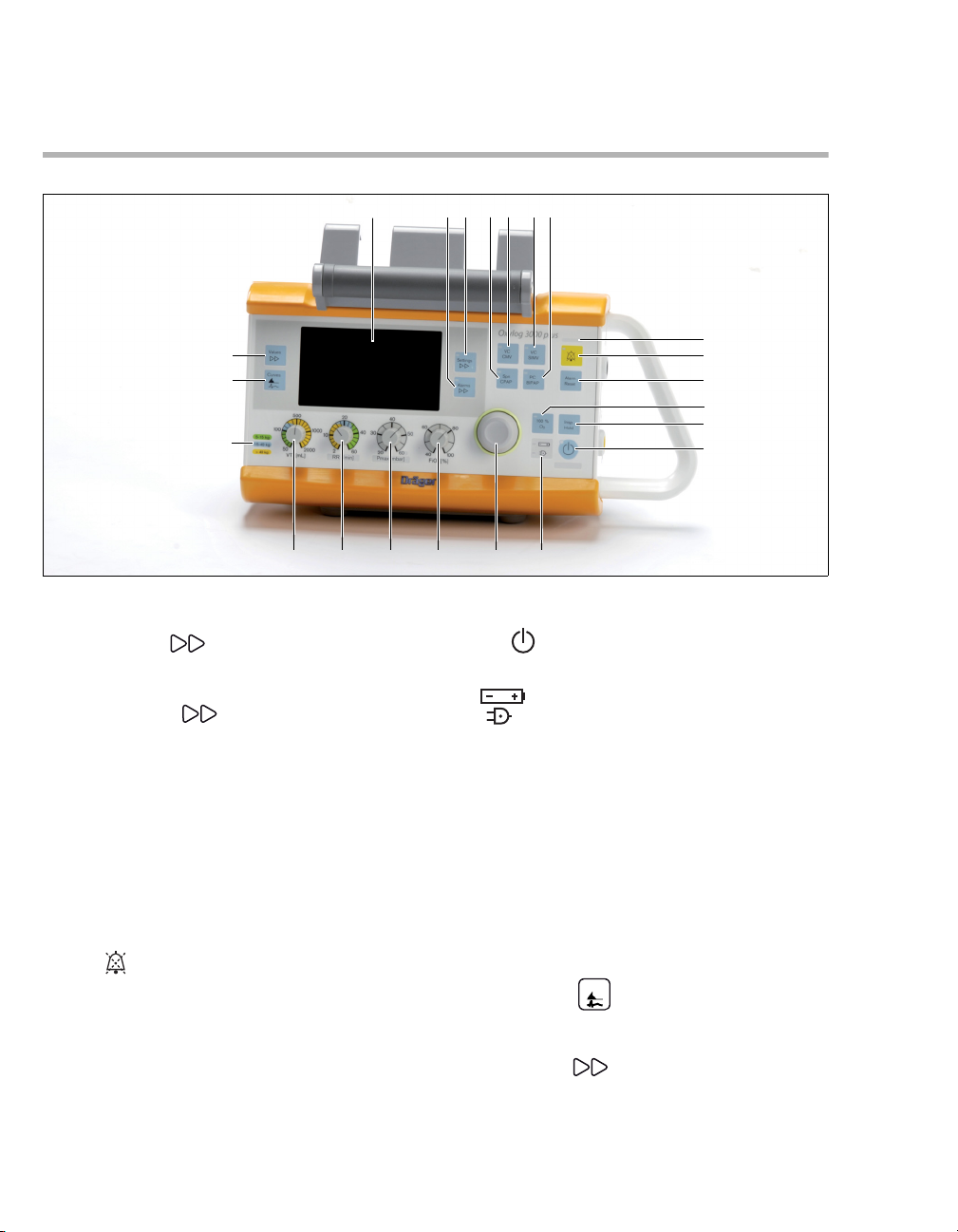
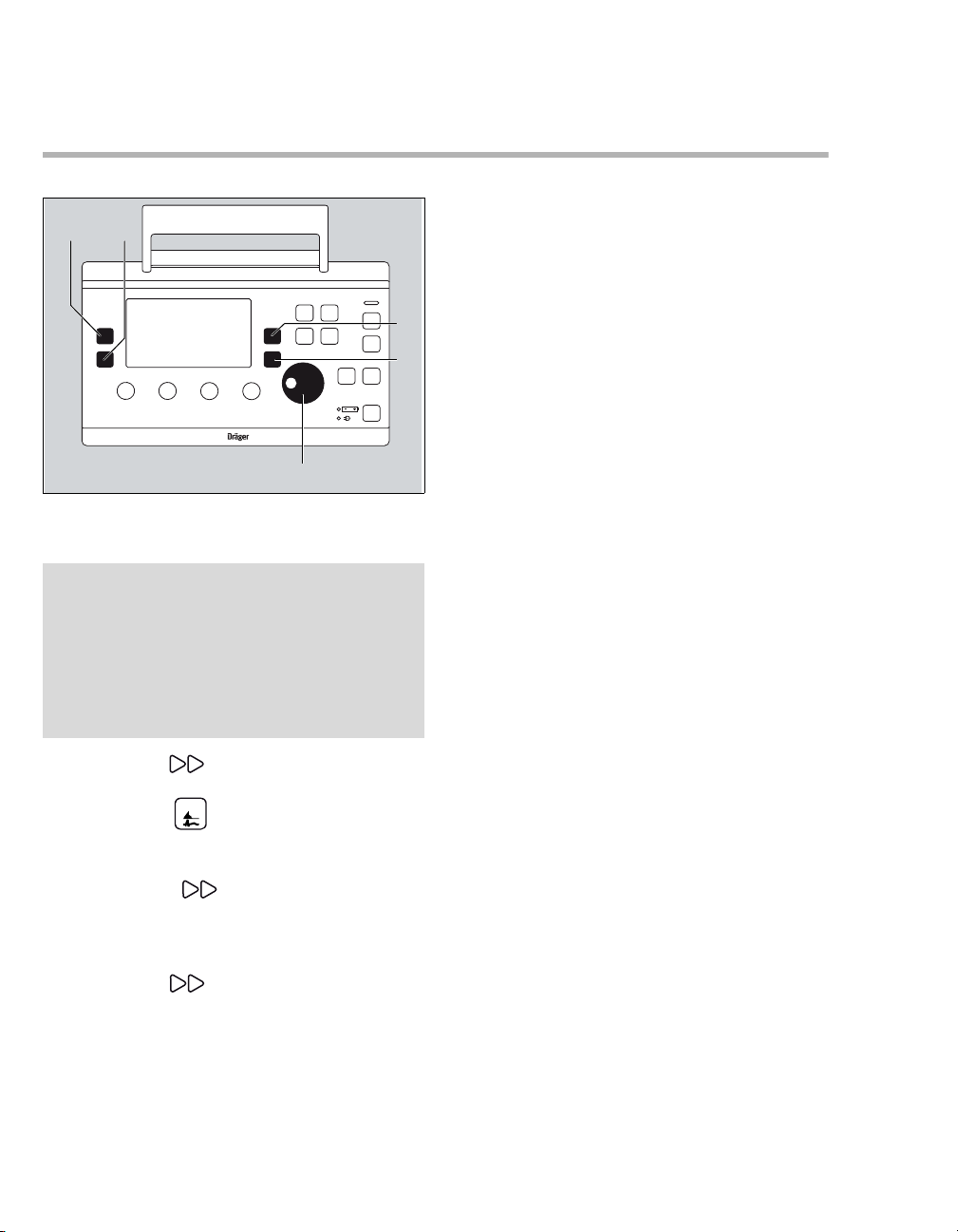
Front panel with all options
A Screen with screen pages for the specific
application
B Key Alarms to display the alarm settings
in the "Settings and Alarms" window and to
change screen pages
C Key Settings to display ventilation
parameters (ventilation screen) in the "Settings
and Alarms" window and to change screen
pages
D Key for setting the ventilation mode SpnCPAP
E Key for setting the ventilation modes VC-CMV /
VC-AC
F Key for setting the ventilation mode VC-SIMV
G Key for setting the ventilation mode PC-BIPAP
H Red and yellow alarm indicators
I Key for suppressing the acoustic alarm sig-
nal for 2 minutes
J Key Alarm Reset for acknowledging alarm
messages
K Key O
100 % O2 for 100 % O2 application, depending
on the option installed at manufacture
2 inhalation for O2 inhalation or key
L Key Insp. Hold for initiating a manual inspira-
tion or for extending the current inspiratory time.
M Key Start/Standby
N Display symbols for the power supply
Charge status of the internal battery
Mains power supply connected
O Rotary knob for making selections, changing
and confirming settings
P Control knob for setting the O
2 concentration
FiO2
Q Control knob for setting the maximum
inspiratory pressure Pmax
R Control knob for setting the respiratory rate RR
S Control knob for setting the tidal volume VT
T Explanation of color codes for quick pre-setting
of RR and VT
U Key Curves to change between the
pressure, flow or CO
and large presentation
V Key Values to change screen pages in
the "Measured Values" window
Curves
2 (optional) curve in small
Front
18
Instructions for Use Oxylog 3000 plus SW 1.n
Page 19

System Overview
B
C
D
E
F
A
G
H
A
B
C
Side view, right
A Emergency air intake
CAUTION
Do not block the emergency air intake. This may
result in ventilator malfunction.
B Knob to secure the battery compartment cover
C Connectors for flow measuring lines
D Gas outlet for breathing hose
E Connector for O
F Connector for power supply
G Connector for CO
H Connector for data communication cable
2 supply
2 sensor
Rear view
Side
A Emergency air intake
CAUTION
Do not block the air intake. This may result in
ventilator malfunction.
B Fresh-gas intake with a filter cartridge
C Protection bracket
CAUTION
Do not use the protection bracket as a handle.
Tilting the device to a vertical position may lead to
airway pressure oscillation.
Rear
Instructions for Use Oxylog 3000 plus SW 1.n 19
Page 20
System Overview
A
E
B
C
D
E
D
C
A
B
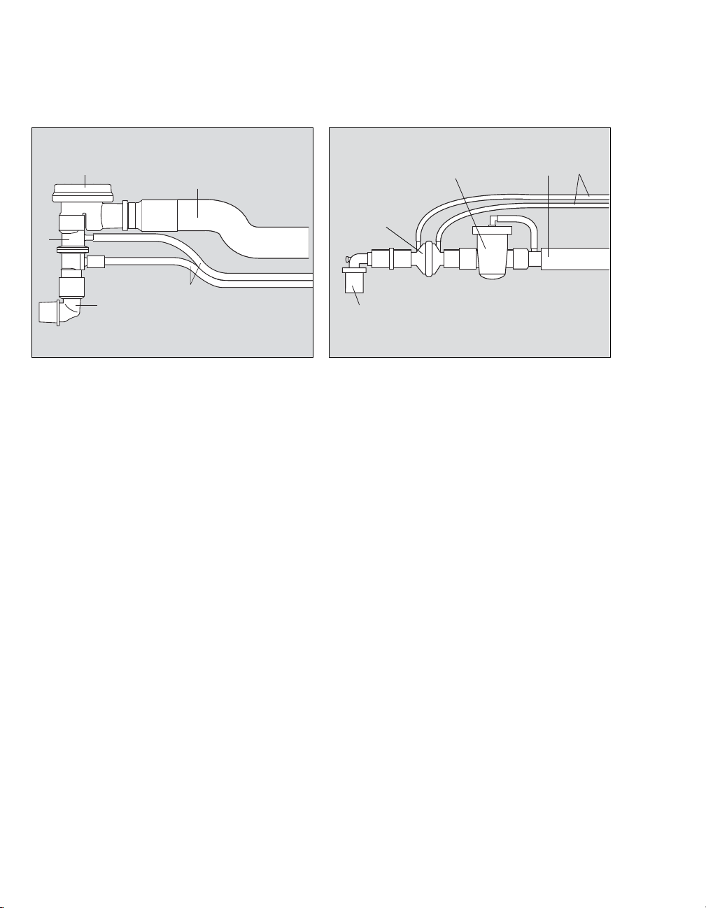
Adult hose system, reusable
A Angled connector
B Flow sensor
C Breathing valve
D Breathing hose
E Flow and pressure measuring hoses
Adult hose system, disposable
001
A Angled connector
B Flow sensor
C Breathing valve
D Breathing hose
E Flow and pressure measuring hoses
002
20
Instructions for Use Oxylog 3000 plus SW 1.n
Page 21
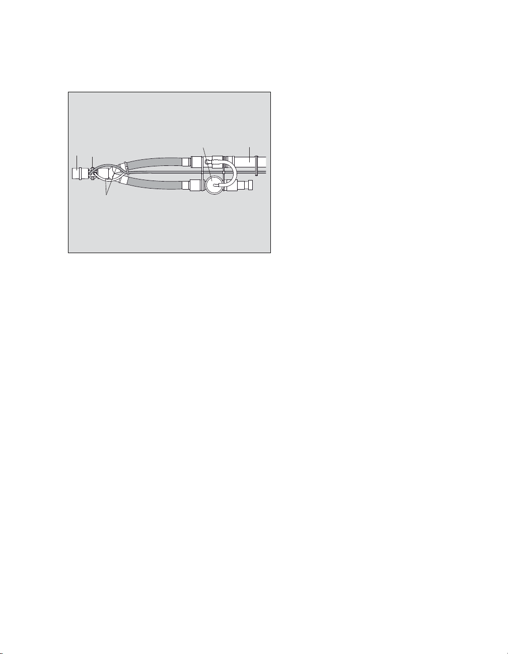
Paediatric hose system, disposable
D
A
E
C
B
A Angled connector
B Flow sensor
C Breathing valve
D Breathing hose
E Flow and pressure measuring hoses
System Overview
08137170
Instructions for Use Oxylog 3000 plus SW 1.n 21
Page 22

System Overview
Range of functions
Ventilation functions of the Oxylog 3000 plus
Ventilation modes:
– Volume-controlled ventilation:
– VC-CMV / VC-AC,
–VC-SIMV.
– Pressure-controlled ventilation:
–PC-BIPAP.
– Support of spontaneous breathing:
– SpnCPAP.
Additional settings for ventilation:
– Pressure Support: in the ventilation modes
VC-SIMV, PC-BIPAP, SpnCPAP,
– Apnoea ventilation: in the ventilation mode
SpnCPAP,
– AutoFlow (optional): in the ventilation modes
VC-CMV, VC-AC and VC-SIMV.
– NIV: in the ventilation modes: SpnCPAP (/PS),
PC-BIPAP (/PS), VC-CMV / AF, VC-AC / AF
and VC-SIMV / AF.
For a detailed description of the ventilation modes
and the additional settings, refer to "Principles of
Operation" on page 157. For abbreviations, see
"Abbreviations" on page 23.
NOTE
In these Instructions for Use the unit of measurement for airway pressure is expressed in [mbar].
However, in some languages the display of the
Oxylog 3000 plus shows [cmH
One [mbar] equals approximately one [cmH
2O].
2O].
Special procedures:
– Inspiration hold,
–O
2 inhalation (optional), with an inhalation
mask.
22
Instructions for Use Oxylog 3000 plus SW 1.n
Page 23

Abbreviations
System Overview
Abbreviation Explanation
100 % O
2 100 % O2 flow
AF AutoFlow
BF Body Floating
bpm Breaths per minute
BTPS Body Temperature, Pressure
Saturated
C Lung compliance
2 Carbon dioxide
CO
CSM Customer Service Mode
ΔPsupp Positive pressure above PEEP
EMC Electromagnetic Compatibility
ESD Electrostatic Discharge
2 Endtidal CO2 concentration
etCO
2 Fractional inspired oxygen
FiO
concentration
FRC Functional Residual Capacity
HME Heat and Moisture Exchange
I:E Ratio inspiratory time to expiratory
time
IPX2 Ingress Protection level 2
IPX4 Ingress Protection level 4
MVe Expiratory minute volume
MVi Inspiratory minute volume
MVespon Spontaneous expiratory minute
volume
NIV Non-invasive ventilation –
mask ventilation
2 Oxygen
O
2-Inhalat. O2 inhalation
O
Paw Airway pressure
PC-BIPAP Pressure Controlled - Biphasic
Positive Airway Pressure
PEEP Positive End Expiratory Pressure
Abbreviation Explanation
PIF Peak Inspiratory Flow
Pinsp Inspiratory pressure
PIP Peak Inspiratory Pressure
Pmax Maximum allowed inspiratory
pressure
Pmean Mean airway pressure
Pplat Plateau pressure
PS Pressure Support
R Resistance
RF Radio Frequency
RR Respiratory Rate (frequency)
RRapn Respiratory Rate during apnoea
ventilation
RRsp Spontaneous Respiratory Rate
SpnCPAP Spontaneous Continuous Positive
Airway Pressure
2 Saturation of peripheral oxygen
SpO
Tapn Time before apnoea is recognized
Te Expiratory time
Ti Inspiratory time
Tplat % Plateau time in % of inspiratory time
UN United Nations
VC-AC Volume Controlled - Assist Control
VC-CMV Volume Controlled - Controlled
Mandatory Ventilation
VC-SIMV Volume Controlled - Synchronized
Intermittent Mandatory Ventilation
VT Tidal volume
VTapn Tidal volume during apnoea
ventilation
VTe Expiratory tidal volume
VTi Inspiratory tidal volume
Instructions for Use Oxylog 3000 plus SW 1.n 23
Page 24
System Overview
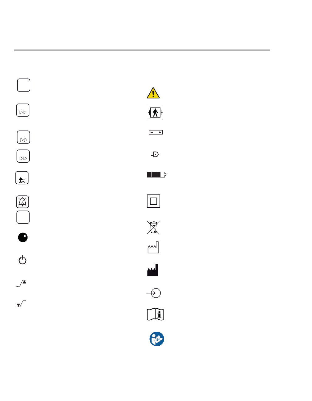
Insp.
hold
Alarms
Symbols
Symbol Explanation
Key for initiating a manual
inspiration or for extending the
current inspiratory time.
Key to display ventilation
Settings
parameters (ventilation screen) in
the "Settings and Alarms" window
and to change screen pages.
Key to display the alarm settings in
the "Settings and Alarms" window
and to change screen pages.
Key to change screen pages in the
Values
"Measured Values" window.
Key to change between the
Curves
pressure, flow or CO
2 (optional)
curve in small and large
presentation.
Key for suppressing the acoustic
alarm signal for 2 minutes.
Key for acknowledging alarm
Alarm
Reset
messages.
Rotary knob
Start / Standby key
Upper alarm limit
Lower alarm limit
! Advisory message
!! Caution message
Symbol Explanation
* Trigger indicator
Warning
Defibrillation-proof type BF applied
part
Charge status of the internal battery
External power supply connected
Battery charge
(example: three quarters full)
Class II equipment, device protected against electric shock with
additional safety precautions such
as double or reinforced insulations,
without protective earthing.
Do not dispose of the device as
municipal waste.
Manufacturing date
Manufacturer
DC input
Operating instructions
Follow Instructions for Use
!!! Warning message
24
Instructions for Use Oxylog 3000 plus SW 1.n
Page 25
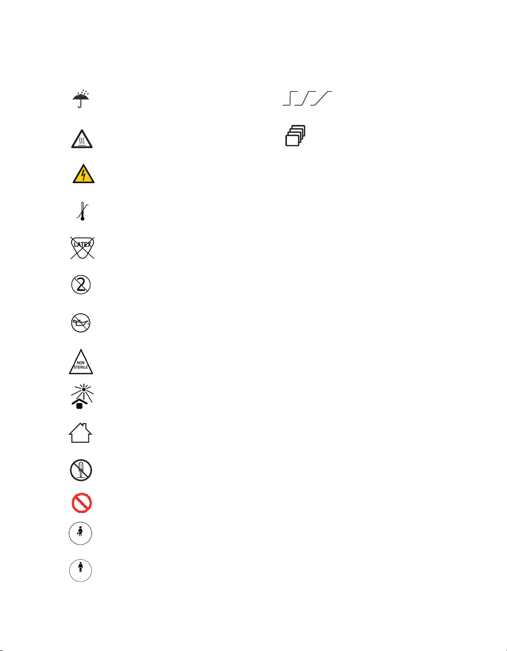
System Overview
Symbol Explanation
For dry locations only
Caution, hot surface!
Warning, dangerous voltage!
Temperature limitations
Latex free
Do not reuse
Do not use oil and grease
Non-sterile
Symbol Explanation
Slope (steep, medium, flat)
Quantity
Keep away from sunlight
For indoor use only
Do not open
Prohibition: Do not obstruct emergency air intake or fresh gas intake
Pediatric
Adult
Paediatric
Adult
Instructions for Use Oxylog 3000 plus SW 1.n 25
Page 26

This page intentionally left blank
26 Instructions for Use Oxylog 3000 plus SW 1.n
Page 27

Operating Concept
Switch on or off . . . . . . . . . . . . . . . . . . . . . . 28
Switch on . . . . . . . . . . . . . . . . . . . . . . . . . . . . 28
Switch off . . . . . . . . . . . . . . . . . . . . . . . . . . . . 28
Ventilation controls . . . . . . . . . . . . . . . . . . . 29
Display operating controls . . . . . . . . . . . . . 30
Additional function keys . . . . . . . . . . . . . . . 31
Screen window structure. . . . . . . . . . . . . . . 32
Operating Concept
Instructions for Use Oxylog 3000 plus SW 1.n 27
Page 28
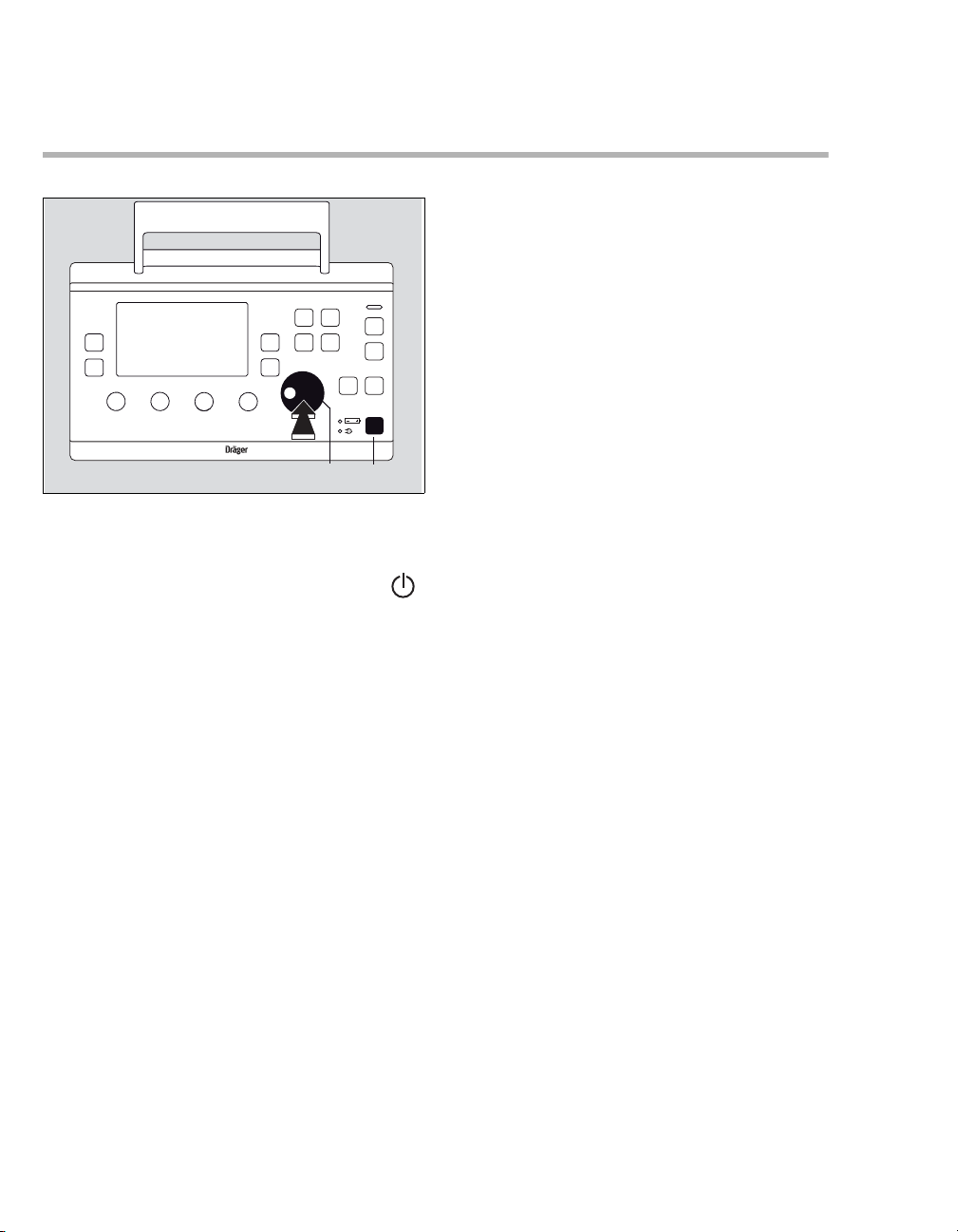
Operating Concept
Oxylog 3000 plus
AB
Switch on or off
Switch on
z To switch the device ON, briefly press the
key (A).
00337170
Switch off
Refer to "Shutdown" on page 82.
28
Instructions for Use Oxylog 3000 plus SW 1.n
Page 29
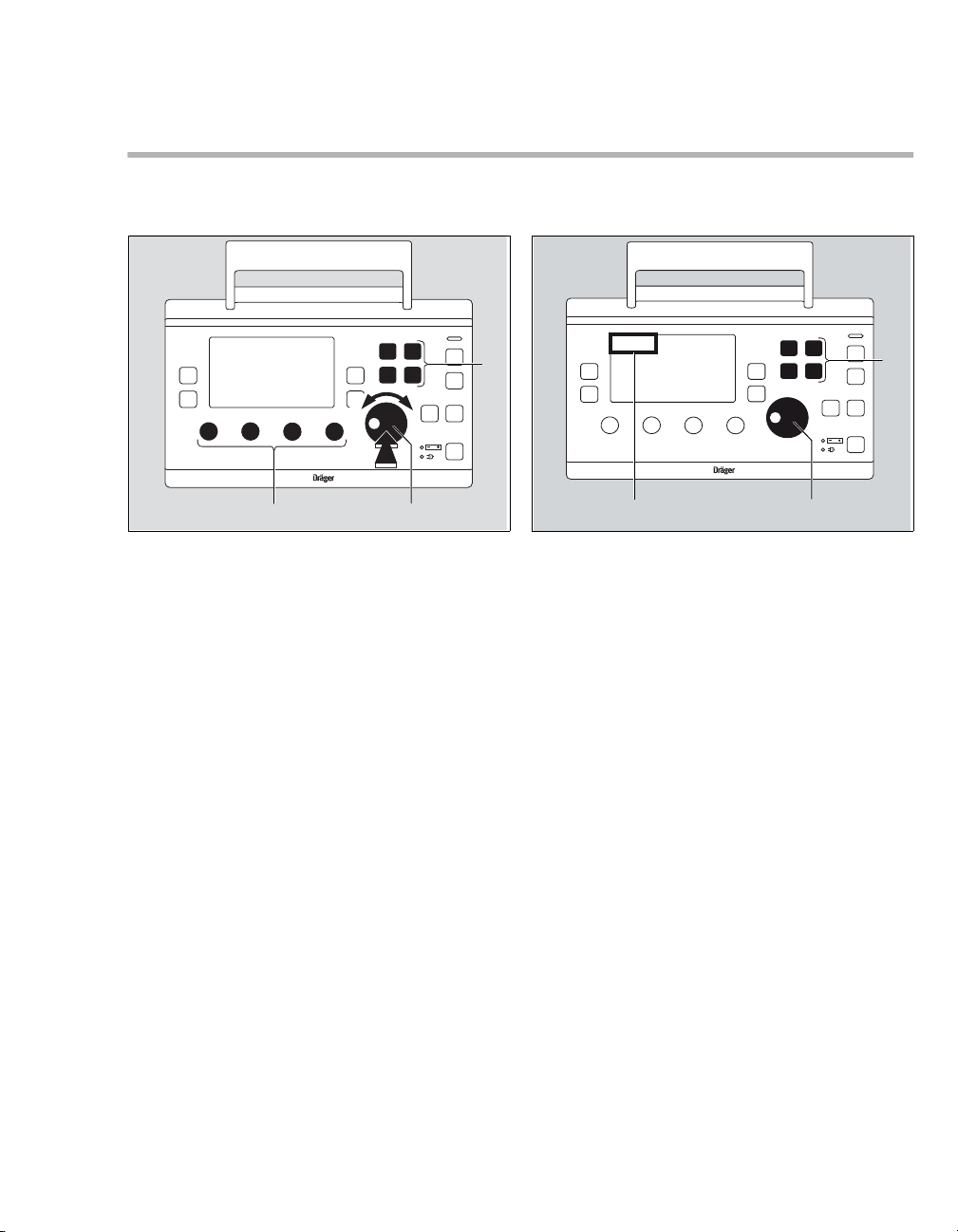
Ventilation controls
BC
A
Oxylog 3000 plus
Operating Concept
General ventilation controls
A Keys for selecting the ventilation modes:
– VC-CMV / VC-AC
–VC-SIMV
– SpnCPAP
– PC-BIPAP.
B Rotary knob.
C Ventilation parameter controls:
– Inspiratory tidal volume VT [mL],
– Ventilation respiratory rate RR [/min],
– Maximum inspiratory pressure Pmax
[mbar],
–O
2 concentration FiO2 [%].
Selecting the ventilation mode
Oxylog 3000 plus
00137170
BC
z Press the appropriate ventilation mode key (A)
for approximately 3 seconds.
Or
1 Press the appropriate ventilation mode key (A).
2 Press the rotary knob (B) to confirm.
The selected ventilation mode will be activated.
The active ventilation mode is displayed in the
upper left corner of the display (C).
A
08537170
Instructions for Use Oxylog 3000 plus SW 1.n 29
Page 30
Operating Concept
Oxylog 3000 plus
B C
D
E
A
Curves
Display operating controls
A Rotary knob for making selections, changing
and confirming settings.
NOTE
Different parameters can be set in the display
window via the rotary knob (e.g. Ti, PEEP, ΔPsupp,
Pinsp).
– To select the parameter: turn rotary knob.
– To activate the parameter: press rotary knob.
– To set the value: turn rotary knob.
– To confirm the value: press rotary knob.
00237170
B Key Values to change screen pages in
the "Measured Values" window.
C Key Curves to change between the
pressure, flow or CO2 (optional) curve in small
and large presentation.
D Key Settings to display ventilation
parameters (ventilation screen) in the "Settings
and Alarms" window and to change screen
pages.
E Key Alarms to display the alarm settings
in the "Settings and Alarms" window and to
change screen pages.
30
Instructions for Use Oxylog 3000 plus SW 1.n
Page 31

Additional function keys
Oxylog 3000 plus
A
B
C
D
Additional keys are positioned on the right side of
the front panel:
A key for suppressing the acoustic alarm sig-
nal for 2 minutes.
B Key Alarm Reset for acknowledging alarm
messages.
C Key Insp. Hold for initiating a manual inspira-
tion or for extending the current inspiratory time.
D Key O
2 inhalation for O2 inhalation or key
100 % O2 for 100 % O2 application, depending
on the option installed at manufacture.
Operating Concept
03237170
Instructions for Use Oxylog 3000 plus SW 1.n 31
Page 32

Operating Concept
A
B
D
C
E
F
BA D
E
C
Screen window structure
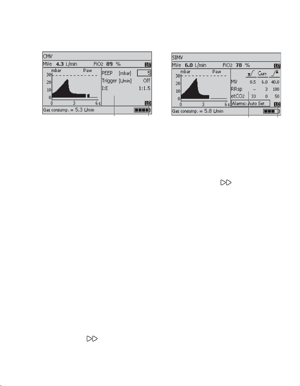
General window structure
A Ventilation mode.
B Alarm messages field.
C Measured values window.
D Curve window.
D and E are combined for a large curve screen.
E Setting and alarm window.
F Information window. For information on the
content, refer to "Messages in the information
window" on page 120.
Measured values window
05437171
A Parameter measured.
B Measured value.
C Unit of measure.
D Measured values 1/7: 1st page of 7 available
pages.
If CO
2 option is not installed: 1/6 available
pages.
E Trigger indicator.
The last page shows an overview of all measured
values.
0583717115637171
32
Instructions for Use Oxylog 3000 plus SW 1.n
Page 33
Operating Concept
BA
A B
Settings window
A Menu for setting supplementary ventilation
parameters in accordance with the desired
ventilation mode.
– AutoFlow (optional)
– Brightness
–CO
2 filter check (optional)
–CO
2 zero calibration (optional)
– Cuvette type (optional)
– HME correction
– Hose type
– I:E / Ti
–NIV
–PEEP
–Pinsp
– RRapn and VTapn
– Slope
– Tapn
– Tplat
– Trigger
–
Δ
Psupp
B Page number: e.g. 1st page of 3 available
pages.
z Press Settings key.
The pages are displayed consecutively.
Alarms window
05737171
A Menu for alarm limits and alarm parameters.
For detailed operating instructions, see "Setting
alarm limits" on page 87.
B Page number: e.g. 1st page of 2 available
pages.
To advance to the next page:
z Press the Alarms key.
The pages are displayed consecutively.
10937171
Instructions for Use Oxylog 3000 plus SW 1.n 33
Page 34

Operating Concept
Pressure curve large view
Curve window showing the airway pressure curve
Paw.
Curves
z Press Curves key multiple times.
Flow curve large view
055371710563717115437171
Curve window showing the flow curve.
CO
2 curve large view
Curve window showing the CO2 curve.
34
Instructions for Use Oxylog 3000 plus SW 1.n
Page 35

Assembly
Internal rechargeable battery . . . . . . . . . . . 37
Removing the battery . . . . . . . . . . . . . . . . . . . 37
Checking the charge status of the battery . . . 37
Installing the battery . . . . . . . . . . . . . . . . . . . . 37
Connecting the power supply . . . . . . . . . . . 38
External power supply . . . . . . . . . . . . . . . . . . 38
External power supply . . . . . . . . . . . . . . . . . 39
External power supply with DC/DC converter 39
External power supply from mains voltage
(AC/DC power pack). . . . . . . . . . . . . . . . . . . . 40
Connecting the gas supply . . . . . . . . . . . . . 41
Supply from an O2 cylinder . . . . . . . . . . . . . . 41
Supply from a piped O2 system . . . . . . . . . . . 42
Assembling the adult reusable hose
system . . . . . . . . . . . . . . . . . . . . . . . . . . . . . . 43
Breathing valve assembly. . . . . . . . . . . . . . . . 43
Hose connections. . . . . . . . . . . . . . . . . . . . . . 44
Assembly
Connecting the adult disposable hose
system . . . . . . . . . . . . . . . . . . . . . . . . . . . . . . 45
Connecting the paediatric disposable
hose system . . . . . . . . . . . . . . . . . . . . . . . . . 46
Connecting the bacterial filter or HME . . . . 47
Connecting the CO
cuvette . . . . . . . . . . . . . . . . . . . . . . . . . . . . . . 48
Hanging the Oxylog 3000 plus on
standard rail systems. . . . . . . . . . . . . . . . . . 49
Instructions for Use Oxylog 3000 plus SW 1.n 35
2 sensor and the
Page 36

Assembly
WARNING
Avoid tripping on, or ensnaring, the breathing
hose, CO
2 sensor cable, AC/DC supply cables,
DC/DC supply cables or compressed gas
hose.
There is a risk of injury and a risk of accidental
extubation of the patient.
WARNING
Do not kink the patient breathing hoses while
ventilating.
Risk of asphyxiation or hypoventilation.
WARNING
Do not use any damaged parts or accessories.
Damaged or deformed parts must be replaced.
WARNING
Data communication between the
Oxylog 3000 plus and other equipment is only
supported when using the MEDIBUS protocol.
WARNING
Electrical connections to equipment, which
are not listed in these Instructions for Use,
should only be made following consultation
with the respective manufacturers.
Equipment malfunction may result as well as
risk of patient injury.
WARNI NG
Always use the angled connector of the hose
system.
If an angled connector is not used, the minute
volume may be measured incorrectly.
WARNI NG
Do not use an adult breathing hose for tidal
volumes below 100 mL.
Risk of CO
2 rebreathing.
CAUTION
Do not use the Oxylog 3000 plus without a dust
filter.
Risk of patient inhaling dust or device damage.
CAUTION
Do not use electrically conductive hoses.
This can endanger the operator and damage the
device during defibrillation.
Risk of electric shock.
WARNING
All equipment connected to the
Oxylog 3000 plus must comply with IEC
60601-1-2.
WARNING
Do not combine parts of different hose sys-
tems, especially for paediatric applications.
Risk of CO2 rebreathing.
36
Instructions for Use Oxylog 3000 plus SW 1.n
Page 37

Internal rechargeable battery
A
B
C
Assembly
Internal power is provided by means of a
removable rechargeable battery. For technical
information, refer to "Technical Data" on page 139.
Removing the battery
1 Turn the knob (C) on the battery compartment
cover (B) counterclockwise to release the cover.
2 Open the battery cover.
3 Remove the battery (A) by pulling the tab.
Installing the battery
1 Insert the battery into the battery compartment.
2 Close the battery cover.
3 Tighten the knob by turning it.
CAUTION
The Oxylog 3000 plus will interrupt ventilation
when the battery is replaced while the device is
switched on and the external power supply is not
connected. Ventilation will always resume with the
last values settings approximately 3 seconds after
inserting a recharged battery.
015
Checking the charge status of the battery
z Press the button on the rechargeable battery.
The charge status is indicated as a percentage
by an indicator.
Instructions for Use Oxylog 3000 plus SW 1.n 37
Page 38

Assembly
Connecting the power supply
External power supply
To recharge the battery and to extend the electrical
operation time, use either:
– DC/DC converter, or
– AC/DC power pack.
For more information refer to page 146.
WARNING
A fully charged battery must always be
installed for safety reasons, even when
operating from an external power supply.
CAUTION
Without a charged battery installed, ventilation will
be interrupted in case of an external power failure.
NOTE
It is recommended to have a fully charged spare
battery available when using the
Oxylog 3000 plus.
Always position the device so that the external
power connector can be easily disconnected from
the ventilator.
38
Instructions for Use Oxylog 3000 plus SW 1.n
Page 39

External power supply
Oxylo
g 3000 plus
12 VDC
24 VDC
28 VDC
D
B
A
C
External power supply with DC/DC converter
WARNING
The DC/DC converter should be used in dry
locations only.
Risk of electric shock or equipment damage.
The DC/DC converter must be used to connect the
Oxylog 3000 plus to onboard DC power supply
systems, e.g. in ambulances. It can be used with
the following voltages: 12 VDC, 24 VDC or
28 VDC. The onboard power supply shall have a
fuse of 10 to 16 A, suitable for DC current.
Outside this range the Oxylog 3000 plus cannot
use the DC input power.
Mount the DC/DC converter on a flat wall and make
sure the wall is solid enough to support the bracket.
Use all four mounting holes (screw size M4).
Assembly
016
1 Plug the large connector (A) of the DC/DC
converter into the on-board supply.
2 Plug the small connector (B) into the DC
connector (C) of the Oxylog 3000 plus.
3 When the Oxylog 3000 plus is correctly
connected to an external power supply, the
indicator (D) lights up.
Instructions for Use Oxylog 3000 plus SW 1.n 39
Page 40
Assembly
Oxylog 3000 plus
A
B
D
C
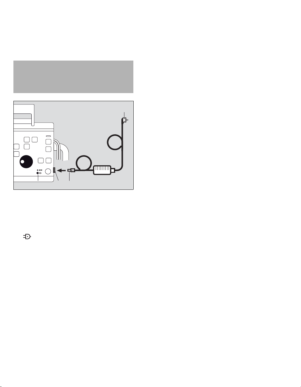
External power supply from mains voltage (AC/DC power pack)
WARNING
The AC/DC power pack must not be used
outdoors.
Risk of electric shock or equipment damage.
1 Connect the mains plug (A) to the mains outlet.
2 Connect the DC connector (B) to the DC
connector (C) of the Oxylog 3000 plus.
3 When the Oxylog 3000 plus is correctly
connected to an external supply, the indicator
(D) lights up.
To isolate the ventilator system from mains, disconnect the power cable from the wall connector.
017
40
Instructions for Use Oxylog 3000 plus SW 1.n
Page 41

Connecting the gas supply
Assembly
Take care when handling O2:
WARNING
Secure O2 cylinders so they cannot fall over.
Keep away from excessive heat.
Risk of explosion.
WARNING
Do not grease or lubricate O2 fittings, such as
cylinder valves and pressure reducers and do
not handle with greasy hands.
Risk of fire.
WARNING
Operate cylinder valves by hand and rotate
slowly to prevent the risk of fire or explosion.
Do not use tools.
WARNING
Only use medical grade oxygen.
WARNING
Always provide adequate ventilation in the
area where the ventilator is being operated, in
order to maintain ambient O2 concentration
below 25 %, to prevent risk of fire.
Supply from an O2 cylinder
WARNING
Always use gas cylinders and pressure regu-
lators that comply with all applicable regulations.
CAUTION
Always use a full O2 cylinder.
Risk of asphyxiation.
1 Connect the pressure reducer (270 to 600 kPa
delivery pressure, 500 kPa nominal pressure)
to the O2 cylinder.
WARNING
Only use a pressure reducer with a relief valve
at the outlet to limit the delivery pressure to a
maximum of 1000 kPa in case of a
malfunction, to prevent damage to the
ventilator through excessive O
pressure on the input.
2 supply
WARNING
No smoking or open flames.
O
2 enhances combustion of other substances
and can intensify fires.
Instructions for Use Oxylog 3000 plus SW 1.n 41
Page 42

Assembly
O
2
A
B
C
A
B
Supply from a piped O2 system
2 Connect the O2 hose (A) to the
Oxylog 3000 plus.
3 Connect the O
(B).
4 Rotate the cylinder valve (C) slowly and open
fully.
WARNING
Do not connect flow control valves or flowme-
ters in the gas supply to the Oxylog 3000 plus.
The ventilator could malfunction.
WARNING
Always check the O2 pressure of cylinder
before use, to prevent insufficient oxygen
supply during use.
2 hose to the pressure reducer
42
018
1 Connect the O2 hose (A) to the
Oxylog 3000 plus.
2 Connect the gas probe (B) to the O
unit until it has properly engaged and the supply
2 is assured.
of O
Instructions for Use Oxylog 3000 plus SW 1.n
019
2 terminal
Page 43

Assembling the adult reusable hose system
A
A
B
C
D
E
Reusable parts must always be sterilized before
use!
Breathing valve assembly
008
WARNING
The rubber disc (A) in the housing must not be
removed, damaged or bent, otherwise the
valve will not work properly and will endanger
the patient.
Risk of CO2 rebreathing.
1 Place the diaphragm (B) in the breathing valve
2 Fit the cover (A) and turn it approximately 60
3 Push the flow sensor (D) onto the breathing
4 Push the angled connector (E) onto the flow
Assembly
housing (C). Ensure that it is inserted correctly.
o
clockwise to secure into position (a click can be
felt).
valve (C). Note the correct alignment of the
parts by the groove in the flow sensor (D) and
the notch on the breathing valve (C).
sensor (D).
009
Instructions for Use Oxylog 3000 plus SW 1.n 43
Page 44

Assembly
A
B
B
B
A
Hose connections
1 Connect the breathing hose (A) to the breathing
valve.
2 Connect the flow measuring lines (B) to the noz-
zles on the flow sensor. Note the different diameters of the hoses and the nozzles when
connecting the flow measuring lines and connect to the correct side.
3 Connect the flow measuring lines (A) to the
Oxylog 3000 plus. Correct alignment is
indicated by a notch on the connector, which
must point away from the breathing hose.
Otherwise, the set will not fit and the measured
values will be incorrect.
4 Connect the breathing hose (B) to the gas outlet
on the Oxylog 3000 plus.
When connecting a hose, check that the hose
011012
setting in the Settings window corresponds to the
connected hose.
44
Instructions for Use Oxylog 3000 plus SW 1.n
Page 45

Connecting the adult disposable hose system
A
B
NOTE
Using a disposable hose may reduce the risk of
cross-infection.
Assembly
013
1 Connect the flow measuring lines (A) to the
Oxylog 3000 plus. Correct alignment is indicated by a notch on the connector, which must
point away from the breathing hose. Otherwise,
the set will not fit and the measured values will
be incorrect.
2 Connect the breathing hose (B) to the gas outlet
on the Oxylog 3000 plus.
When connecting a hose, check that the hose
setting in the Settings window corresponds to the
connected hose.
Instructions for Use Oxylog 3000 plus SW 1.n 45
Page 46

Assembly
B
C
A
Connecting the paediatric disposable hose system
1 Connect the blue flow measuring line (B) to the
blue labeled connector.
2 Connect the transparent flow measuring line (A)
to the other connector.
3 Connect the breathing hose (C) to the gas outlet
on the Oxylog 3000 plus.
When connecting a hose, check that the hose
setting in the Settings window corresponds to the
connected hose.
46
013
Instructions for Use Oxylog 3000 plus SW 1.n
Page 47

Connecting the bacterial filter or HME
Assembly
WARNING
Bacterial filters, HME, and masks increase the
resistance and dead space volume of the
ventilation equipment. Note the
manufacturer’s directions.
Risk of CO2 rebreathing.
NOTE
When using an HME, the measured flow may
deviate from the actual expiratory flow, as
temperature and humidity of the gas are reduced.
The flow and volume measurements can be
corrected for use with an HME. Refer to "Setting
HME correction" on page 80.
It is recommended to use a bacterial filter between
ventilator and patient, to reduce the risk of bacteria,
viruses, fungi or spores being present in the
inspiratory flow.
z Connect the bacterial filter or HME to the angled
connector as follows.
Adult reusable hose:
Adult disposable hose:
014050
Paediatric hose:
010
Instructions for Use Oxylog 3000 plus SW 1.n 47
Page 48

Assembly
A
B
C
D
Connecting the CO2 sensor and the cuvette
51
1 Disconnect the angled connector (A) from the
flow sensor (D).
2 Attach the cuvette (C) to the flow sensor (D),
with the cuvette windows facing the side.
3 Attach the angled connector (A) to the
cuvette (C).
4 Push the CO
with the cable towards the device.
5 Plug the CO
Oxylog 3000 plus. For the connector location,
refer to the section "Side view, right"
on page 19.
6 Insert the CO
the hose.
Alternatively, connect the cuvette (C) directly to the
patient side of the angled connector (A), without
disconnecting the angled connector from the flow
sensor (D).
The CO
maximum of one extension cable. Refer to "List of
Accessories" on page 167.
For CO2 zero calibration and filter check before
ventilation, see page 58. For CO2 zero calibration
and filter check during ventilation, see page 91. For
CO
page 91. For CO2 configuration in the Customer
Service Mode see page 105.
2 sensor cable can be extended with a
2 measurement and cuvette type selection see
2 sensor (B) onto the cuvette (C),
2 sensor into the connector of the
2 sensor cable in the cable clips on
48
Instructions for Use Oxylog 3000 plus SW 1.n
Page 49

Hanging the Oxylog 3000 plus on standard rail systems
The Oxylog 3000 plus can be hung on various rail
systems measuring up to 35 mm diameter by
means of the claw.
– Ensure that the rail is completely inserted in the
claw.
– To ensure optimal functioning of the claw, a
distance of at least 25 mm between rail and wall
is required.
WARNING
Be careful when placing the ventilator on the
rail or bed rim.
Risk of damage to property or personal injury.
CAUTION
The Oxylog 3000 plus is only held by its own
weight when hung on a bar or rail. The
Oxylog 3000 plus must be secured additionally
when being transported, otherwise vibrations may
cause accidental dislodgement.
Assembly
Instructions for Use Oxylog 3000 plus SW 1.n 49
Page 50

This page intentionally left blank
50 Instructions for Use Oxylog 3000 plus SW 1.n
Page 51

Getting Started
Charging the battery . . . . . . . . . . . . . . . . . . 52
Indication of battery capacity / battery
operation. . . . . . . . . . . . . . . . . . . . . . . . . . . . . 52
Determining the approximate pneumatic
operating time. . . . . . . . . . . . . . . . . . . . . . . . 53
Checking readiness for operation . . . . . . . 54
Perform device check. . . . . . . . . . . . . . . . . . . 54
2 zero calibration and filter check
CO
before ventilation (optional) . . . . . . . . . . . . 58
Zero calibration before ventilation . . . . . . . . . 58
2 filter check before ventilation . . . . . . . . . 59
CO
Preparation for use after system check,
CO
2 zero calibration and filter check . . . . . 60
Getting Started
Instructions for Use Oxylog 3000 plus SW 1.n 51
Page 52

Getting Started
Oxylog 3000 plus
BA
Charging the battery
The actual screen display may differ in appearance
or configuration.
NOTE
The ambient temperature must be between 0 and
35 °C when charging the batteries.
When an external supply is available:
1 The green indicator (A) lights up when an
external power source is connected.
2 A three colored indicator (B) lights up to
show the current charge status of the internal
battery:
– Green: the battery is fully charged.
– Yellow: the battery is being charged.
– Red: a battery is not inserted or cannot be
charged.
– Indicators (A) and (B) remain off while the
ventilator is being operated from the internal
battery.
Indication of battery capacity / battery operation
The remaining capacity of the battery is indicated
by Oxylog 3000 plus in 25 % increments in the
lower right section of the information window when
power is ON.
As an example, in the above screen the battery is
75 % charged.
– The accuracy of the battery capacity indicator
02437170
can vary, depending on the age and condition of
the battery. Refer to "Technical Data"
on page 139 for additional information.
– The capacity indication is overwritten when
other messages need to be shown in the
Information window.
– Additional alarms can draw attention to the
remaining operating time of the battery. Refer to
the table "Alarm - Cause - Remedy"
on page 112.
For screen brightness during battery operation,
refer to "Screen brightness" on page 81.
10637171
An external battery charging station connected to
the mains power supply can be used to charge an
extra battery. Refer to the "List of Accessories"
on page 167 for additional information.
52
Instructions for Use Oxylog 3000 plus SW 1.n
Page 53

Determining the approximate pneumatic operating time
O2 supply [L]
(MV +0.5*) [L/min]
420
5.8
A
Getting Started
Example for supply of O2:
– Cylinder pressure measured on the pressure
gauge of the pressure reducer: 20,000 kPa
(200 bar)
– Liquid capacity of the O
Supply of O
2:
2 cylinder: 2.1 L
2.1 L x 20,000 kPa = approx. 420 L at environmental pressure level.
Example for pneumatic operation time:
– VC-CMV mode, frequency 10 breaths/min,
VT = 0.53 L, O
2 = 100 %
– Minute volume = 10 breaths/min x 0.53 L =
5.3 L/min
Operation time =
* Calculated with average gas consumption of
ventilator: 0.5 L/min
Example:
13637171
A O2 consumption = 5.3 L/min
Operation time = = approx. 72 minutes
The pneumatic operation time increases when
Oxylog 3000 plus operates with O
of less than 100 % O2, as ambient air is drawn into
the device.
The amount of gas from the high-pressure supply,
which is currently being consumed, is indicated by
the Oxylog 3000 plus in the lower left section of the
information window in L/min. This display is overwritten when a higher priority message is activated.
Instructions for Use Oxylog 3000 plus SW 1.n 53
2 concentration
Page 54

Getting Started
A
C
B
Checking readiness for operation
The device check should be performed:
– Before every use of the device if the breathing
hose was changed.
– At least every six months.
The Oxylog 3000 plus interrupts the device check if
a fault is detected.
The relevant fault is indicated on the screen.
WARNING
The patient may be endangered if the device
check is not completed successfully.
Perform device check
The device check consists of the following steps:
– Connect the test lung
– Switch the device ON
– Check connections
– System check
– Power supply failure check.
The duration of the device check is approximately
3 minutes.
Connect the test lung
021
1 Make sure that the angled connector (A) is
connected to the flow sensor.
2 Connect the catheter mount (B) of the test lung,
diameter 7 mm, to the angled connector.
The catheter mount simulates the resistance of
the airways.
3 Connect the balloon (C) of the test lung. Refer
to "List of Accessories" on page 167.
NOTE
BTPS values of a test lung are not the same as the
BTPS values of a patient. The Oxylog 3000 plus
measures and adapts according to BTPS values of
a patient. Therefore, when a test lung is
connected, the MVe and VTe indicated on display
may differ from the MVe and VTe that is set by the
operator.
54
Instructions for Use Oxylog 3000 plus SW 1.n
Page 55

Getting Started
Oxylog 3000 plus
A
B
Switch the device ON
1 To switch the device ON briefly press
the key (A).
The device performs a selftest and the operator is
prompted, on the display, to activate the
configuration menu or device check:
Press rotary knob for device check and
configuration
2 Press the rotary knob (B) to confirm, before the
black progess bar is complete. The start-up
screen appears:
3 Select Device check in the start-up menu and
02211937171
confirm.
NOTE
The device check can be discontinued at any time
by pressing the Alarm Reset key.
NOTE
During device check, the connections (gas supply,
hose type) and the system (flow, pressure levels,
alarm signals and knobs) are checked.
14737171
Instructions for Use Oxylog 3000 plus SW 1.n 55
Page 56

Getting Started
Oxylog 3000 plus
A
Check connections
1 Ensure that the gas supply has been
connected.
2 Select and confirm the appropriate hose type.
3 Ensure that the test lung has been connected.
The Oxylog 3000 plus automatically checks if a
test lung has been connected. The device
check is interrupted if a test lung is not detected
within one minute. The check is continued when
the test lung is detected.
4 The Oxylog 3000 plus automatically checks if
the detected hose differs from the selected
hose type.
If the wrong hose type is selected:
– Press the Alarm Reset key to cancel the
device check.
– Restart the device check.
– Select the correct hose type.
System check
023
5 Set the control knobs (A) below the display to
the required values.
The Oxylog 3000 plus successively activates
the audible and optical alarm signals and
prompts the operator to acknowledge each
signal.
6 Confirm the audible and optical alarm signals.
The device check continues automatically.
During the automatic test sequence, the
Oxylog 3000 plus checks the flow, pressure levels and alarm signals. Corresponding sounds
are heard.
The bar graph shows the progress made by the
check.
The result is displayed on the last page of the
device check screens. If all tests are completed
successfully, the device will go to the last page.
If a test fails, the device will go directly after the
failed test to the last page, without performing
the other tests.
After confirmation, the system returns to the
menu screen.
56
If the service inspection date has been passed without servicing, the text Service date overdue ! will
appear in the window after finishing the device
check. In this case the device must be serviced
immediately.
Instructions for Use Oxylog 3000 plus SW 1.n
Page 57

Getting Started
High airway pressure and disconnection alarm check
Check the high airway pressure alarm
1 Ventilate the test lung in CMV mode.
2 Press the test lung manually, until the airway
pressure exceeds the set Pmax.
3 Check if the P
AW high alarm occurs.
Check the alarm in case of hose system disconnection
1 Ventilate the test lung in CMV mode.
2 Disconnect the breathing hose and/or flow mea-
suring lines from the ventilator.
3 Check if an applicable alarm occurs.
Power supply failure check
A monthly check of the power supply failure alarm
is recommended.
1 Switch the device on.
2 Disconnect the external power supply.
3 Remove the battery to activate the acoustic
alarm signal.
4 Listen for the acoustic alarm signal.
If the device check is not completed successfully:
1 Refer to "Error messages during the device
check" on page 122 of the section "Problem
Solving".
2 Contact your local DrägerService for support.
NOTE
If no alarm is heard, contact DrägerService.
5 When the power supply failure alarm test is
completed, reinstall the battery into the battery
compartment of the Oxylog 3000 plus.
6 Connect the external power supply.
Troubleshooting
WARNING
The ventilator is ready for operation only after
all functional tests have been successfully
performed.
Instructions for Use Oxylog 3000 plus SW 1.n 57
Page 58

Getting Started
Oxylog 3000 plus
A
B
CO2 zero calibration and filter check before ventilation (optional)
The CO2 zero calibration and filter check only work
if the CO
sensor is present.
1 To switch the device ON briefly press the
The device performs a selftest and the operator is
prompted, on the display, to activate the
configuration menu or device check:
Press rotary knob for device check and
configuration
2 option has been installed and if the CO2
key (A).
3 Select CO
2 zero calibration and filter check
in the start-up menu and confirm.
The function CO
2 Zero Calibration and Filter
check is displayed only if the option is avail-
able.
NOTE
02211937171
The CO2 zero calibration and filter check can be
discontinued at any time by pressing the Alarm
Reset key.
Zero calibration before ventilation
The zero calibration is performed with a clean CO2
sensor that has been removed from the cuvette!
14737171
2 Press the rotary knob (B) to confirm, before the
black progress bar is complete.
58
NOTE
Do not breathe on the CO2 sensor during zero
calibration, otherwise the zero calibration can fail
or the zero calibration can pass with an invalid zero
value.
Instructions for Use Oxylog 3000 plus SW 1.n
Page 59

Getting Started
A
B
A
B
CO2 filter check before ventilation
NOTE
Before the CO2 filter check, you need to have finished a successful CO
wise the CO
2 filter check may be outside of the
tolerance range.
17914837171
1 Remove the CO2 sensor (A) from the cuvette
1 Remove the CO2 sensor (A) from the cuvette
(B).
(B).
2 Attach the CO
3 Select Filter check.
2 Select and activate Zero calibration. The
screen displays the text Remove sensor from
cuvette. Confirm with rotary knob.
3 Confirm. The zero calibration starts and the line
displays Zero calibration in progress. After a
4 Confirm. The filter check starts and the screen
displays Filter check in progress. After a
successful filter check, the line briefly displays
Filter check OK.
5 Press Alarm Reset to exit.
successful zero calibration, the line briefly
displays Zero calibration OK.
6 Attach the CO
4 Press Alarm Reset to exit.
5 Attach the CO
2 sensor back to the cuvette.
If the check was not successful:
The Oxylog 3000 plus displays the alarm Filter
check failed. The test value is outside the
If zero calibration was not successful:
The Oxylog 3000 plus displays the alarm Zero
calibration failed.
z Repeat zero calibration.
If zero calibration is still not possible:
1 Check whether the sensor (A) is soiled and
clean it if necessary. If the sensor is defective,
replace the sensor.
2 Repeat zero calibration.
Instructions for Use Oxylog 3000 plus SW 1.n 59
permissible tolerance.
z Check whether the sensor (A) or test filter (B) is
soiled and clean them if necessary. Repeat the
2 filter check.
CO
If the check was still not successful:
z Check the CO
For connecting the CO
page 48. For CO2 zero calibration and filter check
during ventilation, see page 91. For CO2 measurement see page 91. For CO
Customer Service Mode see page 105.
2 zero calibration. Other-
2 sensor (A) to the test filter (B).
2 sensor back to the cuvette.
2 calibration with test gas.
2 sensor and cuvette see
2 configuration in the
177
Page 60

Getting Started
Preparation for use after system check, CO2 zero calibration and filter check
1 Assemble the Oxylog 3000 plus for operation.
Refer to "Assembly" on page 35.
2 Connect to the power supply and gas supply.
Refer to "Internal rechargeable battery"
on page 37 and "Connecting the gas supply"
on page 41.
3 Start the ventilator:
z Select Start ventilation from the menu and
confirm.
Or
z Press the Alarm Reset key.
14737171
60
Instructions for Use Oxylog 3000 plus SW 1.n
Page 61

Operation
Starting operation. . . . . . . . . . . . . . . . . . . . . 62
Switch the device ON . . . . . . . . . . . . . . . . . . . 62
Preparing ventilation mode . . . . . . . . . . . . . 64
To activate a ventilation mode . . . . . . . . . . . . 64
Setting ventilation parameters . . . . . . . . . . . . 64
VC-CMV, VC-AC . . . . . . . . . . . . . . . . . . . . . . 65
Trigger (VC-AC) . . . . . . . . . . . . . . . . . . . . . . . 66
Setting AutoFlow (optional) . . . . . . . . . . . . . . 67
Cardio-pulmonary resuscitation (CPR). . . . . . 67
VC-SIMV, VC-SIMV/PS . . . . . . . . . . . . . . . . . 68
Setting Pressure Support VC-SIMV/PS . . . . . 69
Setting AutoFlow (optional) . . . . . . . . . . . . . . 70
PC-BIPAP, PC-BIPAP/PS . . . . . . . . . . . . . . . 71
Setting Pressure Support PC-BIPAP/PS . . . . 72
Operation
Sp nCPA P, SpnC PAP/ PS . . . . . . . . . . . . . . . . 73
Apnoea ventilation . . . . . . . . . . . . . . . . . . . . . 74
Setting Pressure Support Spn-CPAP/PS . . . . 75
Cardio-pulmonary resuscitation (CPR). . . . . . 75
NIV – Non-invasive ventilation (Mask
ventilation) . . . . . . . . . . . . . . . . . . . . . . . . . . 76
Special functions . . . . . . . . . . . . . . . . . . . . . 77
Manual inspiration / Inspiration hold . . . . . . . . 77
100 % O2 (optional) . . . . . . . . . . . . . . . . . . . . 77
O2 inhalation (optional) . . . . . . . . . . . . . . . . . 77
O2 concentration with "O2 blending". . . . . 79
Setting HME correction . . . . . . . . . . . . . . . . 80
Calibration. . . . . . . . . . . . . . . . . . . . . . . . . . . 81
Screen brightness . . . . . . . . . . . . . . . . . . . . 81
Alarm volume . . . . . . . . . . . . . . . . . . . . . . . . 81
Shutdown . . . . . . . . . . . . . . . . . . . . . . . . . . . 82
Instructions for Use Oxylog 3000 plus SW 1.n 61
Page 62

Operation
Oxylog 3000 plus
A
B
Starting operation
The actual screen display may differ in appearance
or configuration.
WARNING
Only use a ventilator that has been cleaned,
disinfected and successfully tested to be
ready for operation, to prevent a health risk for
the patient and user.
Refer to the chapter "Cleaning, Disinfection
and Sterilization" on page 123.
CAUTION
When using the ventilator in very low ambient
temperatures, always consider that the cold gas
will expand due to the warming by the patients
body. Carefully monitor the MVe.
Risk of hyperventilation.
CAUTION
In very high ambient temperatures, avoid mixing
with ambient air: always set FiO
2 to 100 % O2.
Exposing the patient to very warm inspiratory gas
may cause lung damage.
Switch the device ON
0133717011937171
z To switch the device ON, briefly press the
key (A).
62
The Oxylog 3000 plus performs a selftest. The
selftest will be completed in approximately six
seconds.
During the selftest, the system briefly displays the
starting page with a bar graph indicating the
progress of the selftest, the software version, the
activated software options and a prompt for the
operator to activate the device check by pressing
the rotary knob (B).
Instructions for Use Oxylog 3000 plus SW 1.n
Page 63

If the rotary knob (B) is not pressed during the selftest, the hose selection page is displayed.
Select the connected hose type, as seen in the
above graphic, by rotating the rotary knob (B) and
confirm by pressing the rotary knob (B). The
ventilator now automatically begins ventilation with
the default settings.
NOTE
As long as the hose selection page is shown, the
patient is not being ventilated.
Operation
14937171
NOTE
The request to select the hose type can be
configured. Refer to "Customer Service Mode"
on page 98.
Starting screen with default settings.
The default settings can be configured in Customer
Service Mode. Refer to "Set start-up settings"
on page 100.
10437171
Instructions for Use Oxylog 3000 plus SW 1.n 63
Page 64

Operation
Preparing ventilation mode
To activate a ventilation mode
1 Press and hold a ventilation mode key for
approximately 3 seconds.
Or
2 Press a ventilation mode key and confirm by
pressing the rotary knob.
The new ventilation mode selected is now effective.
For an overview of all ventilation modes, refer to
"Range of functions" on page 22. For a detailed
explanation on all ventilation modes, refer to
"Principles of Operation" on page 157.
Setting ventilation parameters
1 Set the required control knob below the display.
Or
2 Select, set and confirm a parameter on the
display with the rotary knob.
If the changed settings are not confirmed after
5 seconds, the alarm ! Confirm settings appears.
If the settings are still not confirmed after
10 seconds, the alarm ! Settings not confirmed
appears. After that the former settings are restored.
12137171
When the PEEP setting is increased above
10 mbar, a message Confirm PEEP above 10
mbar? will appear to request confirmation of the
change. The PEEP setting can be increased to the
desired setting after the message is confirmed with
the rotary knob.
The device can be configured to show Ti or I:E as
a primary parameter that can be set. If Ti is
configured as the primary parameter, I:E will be
shown in the information window when Ti is
selected, and vice versa. This configuration will
apply to all ventilation modes. Refer to the
"Customer Service Mode" on page 98.
64
Instructions for Use Oxylog 3000 plus SW 1.n
Page 65

VC-CMV, VC-AC
Paw
Flow
T
insp
T
e
P
plat
Plateau time
Tplat
1
RR
Insp. Flow
t
t
Pmax
PEEP
Exp. Flow
Operation
VC-CMV -Volume Controlled - Controlled
Mandatory Ventilation
Volume-controlled ventilation with fixed mandatory
minute volume MV, which is set with tidal volume
VT and respiratory rate RR.
WARNING
Only use VC-CMV for patients who are not
spontaneously breathing. Otherwise, the
patient may be put at risk by not receiving
sufficient ventilation.
Use VC-AC for patients with partial
spontaneous breathing.
Set the ventilation pattern with the controls below
the display:
– Tidal volume VT.
– Ventilation respiratory rate RR.
(minimum possible frequency: 5 per min).
– Maximum airway pressure Pmax.
–O
2 concentration FiO2.
The following can be set on the display:
– Positive end expiratory pressure PEEP.
– Sensitivity Trigger.
– Ventilation time ratio I:E or inspiratory time Ti.
When setting the ventilation respiratory rate RR,
tidal volume VT or I:E / Ti, the associated values for
inspiration flow and Ti / I:E are automatically
025
displayed in the information window.
– Plateau time Tplat %, in % of the inspiratory
time.
– AutoFlow (optional).
1043717110537171
Instructions for Use Oxylog 3000 plus SW 1.n 65
Page 66

Operation
– Hose type
The selected hose type must match the hose
type in use. Otherwise a correct volume
measurement cannot be guaranteed.
Trigger (VC-AC)
NOTE
When in VC-CMV and the trigger is set to a value,
the ventilation mode changes to VC-AC.
VC-AC –Volume Controlled - Assist Control
For synchronization with the patient's spontaneous
inspiratory efforts.
1373717114537171
The mandatory breaths are synchronized with the
patient's spontaneous inspiratory efforts when the
trigger is activated and the trigger sensitivity is set.
In this case, the actual respiratory rate may be
higher than the set ventilation respiratory rate RR.
Successful patient triggering is briefly indicated by
an asterisk (*) on the left side of the curve window.
– Cuvette type (optional)
NOTE
The cuvette windows of the reusable cuvette and
disposable cuvette have different optical properties. Therefore, the correct cuvette type must be
selected in the Setting menu. Otherwise the zero
point is shifted by up to ± 8 mmHg of CO
2.
66
Instructions for Use Oxylog 3000 plus SW 1.n
Page 67

Operation
Oxylog 3000 plus
A
Activating/setting the trigger
1 Press the key Settings (A) until the trig-
ger parameter is displayed.
2 Select the line Trigger on the display and then
set and confirm the value with the rotary knob.
Small value = high sensitivity.
The ventilation mode AC
is shown on the display.
Deactivating trigger
1 Set a value less than 1 L/min or greater than
15 L/min (off is displayed instead of a value).
2 Press the rotary knob to confirm.
The last effective trigger value is adopted by the
ventilator when changing from VC-AC to PC-BIPAP
or SpnCPAP.
Setting AutoFlow (optional)
The following can also be set on the display for
VC-CMV and VC-AC:
– The AutoFlow function AutoFlow-AF.
00537170
When AutoFlow is switched on, the setting Tplat%
is no longer valid, and Slope must be set.
For more information on AutoFlow, refer to
"AutoFlow" on page 162.
Cardio-pulmonary resuscitation (CPR)
During CPR, the airway pressure Paw is increased
because of chest compressions.
The Oxylog 3000 plus will try to limit the airway
pressure Paw to the set Pmax, without ending the
inspiration prematurely.
However, if due to compressions the airway
pressure Paw exceeds the set Pmax by 5 mbar,
the Oxylog 3000 plus cycles to the expiratory
phase.
Therefore in general, if Pmax is set to a higher
value, a higher minute volume is possible.
However, this increases the intra-thoracic pressure
and may reduce coronary perfusion.
10737171-1
Instructions for Use Oxylog 3000 plus SW 1.n 67
Page 68

Operation
VC-SIMV, VC-SIMV/PS
Volume Controlled - Synchronized Intermittent
Mandatory Ventilation
Paw
PEEP
P
max
Pressure
support PS
short
rise time
long
rise time
t
i
T
Flow
1
RR
Insp. Flow
Trigger window
t
For patients with inadequate spontaneous breathing, or for patients who are to be weaned gradually.
Fixed mandatory minute volume MV is set with tidal
volume VT and ventilation respiratory rate RR. The
patient can breathe spontaneously between the
mandatory breaths and thus contribute to the total
minute volume. Spontaneous breathing can be
assisted with PS.
Set the ventilation pattern with the controls below
the display:
– Tidal volume VT.
– Respiratory rate RR.
(minimum possible respiratory rate: 2 per min).
– Maximum airway pressure Pmax.
–O
2 concentration FiO2.
The following can be set on the display:
– Positive end expiratory pressure PEEP.
– Pressure Support
Δ
Psupp above PEEP.
– Sensitivity Trigger.
Successful patient triggering is indicated by an
asterisk (*) on the left side of the curve window.
– Ventilation time ratio I:E or inspiratory time Ti.
027
When setting the ventilation respiratory rate RR,
tidal volume VT or I:E / Ti, the associated values for
inspiration flow and Ti / I:E are automatically displayed in the information window.
– Plateau time Tplat %, in % of the inspiratory
time.
– AutoFlow (optional).
10737171-115837171-1
68
Instructions for Use Oxylog 3000 plus SW 1.n
Page 69

– Insp.term.%PIF
Inspiration termination criteria of pressure supported strokes, as percentage of the peak
inspiratory flow (PIF).
– Hose type
The selected hose type must match the hose
type in use. Otherwise a correct volume measurement cannot be guaranteed.
Operation
Setting Pressure Support VC-SIMV/PS
The following can also be set on the display for
VC-SIMV:
1443717114337171
– Setting on page 1: Pressure Support
above PEEP.
– Setting on page 2: When
Δ
Psupp is set above
0 mbar, the pressure rise time Slope can be
set.
Flat slope = long pressure rise time
Medium slope = medium pressure rise
time
Steep slope = short pressure rise time.
Δ
Psupp
14237171-1
– Cuvette type (optional)
NOTE
The cuvette windows of the reusable cuvette and
disposable cuvette have different optical properties. Therefore, the correct cuvette type must be
selected in the Setting menu. Otherwise the zero
point is shifted by up to ± 8 mmHg of CO
Instructions for Use Oxylog 3000 plus SW 1.n 69
2.
Page 70

Operation
Setting AutoFlow (optional)
The following can also be set on the display for
VC-SIMV and VC-SIMV/PS:
– The AutoFlow function AutoFlow-AF.
When AutoFlow is switched on, the setting Tplat%
is no longer valid, and Slope must be set.
For more information on AutoFlow, refer to
"AutoFlow" on page 162.
10737171-1
70
Instructions for Use Oxylog 3000 plus SW 1.n
Page 71

PC-BIPAP, PC-BIPAP/PS
Operation
Pressure Controlled - Biphasic Positive Airway
Pressure
Without
spontaneous breathing
Short
Paw
rise time
PEEP
T
i
Flow
1
RR
With
spontaneous breathing
Long
rise time
insp
P
Trigger window
Pressure
support PS
Short
rise time
Long
rise time
t
t
Pressure-controlled ventilation combined with
spontaneous breathing throughout the respiratory
cycle and variable Pressure Support at CPAP level.
For patients without spontaneous breathing, to
spontaneously breathing patients shortly before
extubation. The patient is weaned by gradually
reducing the mandatory portion of the total minute
volume MV and by reducing the Pressure Support
ΔPsupp.
The following can be set on the display:
– Positive end expiratory pressure PEEP.
– Inspiratory pressure Pinsp.
– Pressure Support
Δ
Psupp above PEEP.
– Sensitivity Trigger.
Successful patient triggering is indicated by an
asterisk (*) on the left side of the curve window.
028
1083717114137171
– Ventilation time ratio I:E or inspiratory time Ti.
The mandatory portion of the total minute volume
MV is set via the inspiratory pressure Pinsp, PEEP
and ventilation respiratory rate RR.
Refer to the description on page 161 for details.
Set the ventilation pattern with the controls below
– Pressure rise time Slope (effective for the PC-
BIPAP stroke and Pressure Support ΔPsupp).
– NIV - Non-invasive ventilation.
Refer to "NIV – Non-invasive ventilation (Mask
ventilation)" on page 76.
the display:
– Respiratory rate RR.
– Maximum airway pressure Pmax.
–O
2 concentration FiO2.
Instructions for Use Oxylog 3000 plus SW 1.n 71
Page 72

Operation
– Insp.term.%PIF
Inspiration termination criteria of pressure supported strokes, as percentage of the peak
inspiratory flow (PIF).
– Hose type
The selected hose type must match the hose
type in use. Otherwise a correct volume measurement cannot be guaranteed.
Setting Pressure Support PC-BIPAP/PS
The following can also be set on the display for
PC-BIPAP:
1403717115037171
Δ
– Setting on page 1: Pressure Support
above PEEP.
– Setting on page 2: Pressure rise time Slope.
Flat slope = long pressure rise time
Medium slope = medium pressure rise
time
Steep slope = short pressure rise time.
Psupp
12437171
– Cuvette type (optional)
NOTE
The cuvette windows of the reusable cuvette and
disposable cuvette have different optical properties. Therefore, the correct cuvette type must be
selected in the Setting menu. Otherwise the zero
point is shifted by up to ± 8 mmHg of CO
2.
72
Instructions for Use Oxylog 3000 plus SW 1.n
Page 73

SpnCPAP, Sp n C PA P / P S
Spontaneous Continuous Positive Airway
Pressure
WARNING
Only use SpnCPAP (/PS) for patients with
sufficient spontaneous breathing.
Otherwise there is a risk of the patient
receiving insufficient ventilation.
Operation
Set the ventilation pattern with the controls below
the display:
– Maximum airway pressure Pmax.
–O2 concentration FiO2.
The following can be set on the display:
– Positive end expiratory pressure PEEP.
– Pressure Support
Δ
Psupp above PEEP.
– NIV - Non-invasive ventilation.
Refer to "NIV – Non-invasive ventilation (Mask
ventilation)" on page 76.
– Insp.term.%PIF
Inspiration termination criteria of pressure supported strokes, as percentage of the peak
inspiratory flow (PIF).
– Hose type
The selected hose type must match the hose
type in use. Otherwise a correct volume measurement cannot be guaranteed.
15737171
– Cuvette type (optional)
NOTE
The cuvette windows of the reusable cuvette and
disposable cuvette have different optical
properties. Therefore, the correct cuvette type
must be selected in the Setting menu. Otherwise
the zero point is shifted by up to ± 8 mmHg of CO
1513717115237171
2.
Instructions for Use Oxylog 3000 plus SW 1.n 73
Page 74

Operation
Paw
Flow
Apnea alarm time
Tapn
Start
apnea ventilation
with apnea alarm
t
t
1
RRapn
Pmax
Oxylog 3000 plus
A B
Apnoea ventilation
Apnoea back-up ventilation is only applicable when
using the SpnCPAP mode. In the event of an
apnoea, the ventilator will automatically activate
volume-controlled mandatory ventilation - (VCCMV).
When an apnoea occurs, the device
simultaneously issues an alarm signal and
switches to volume controlled ventilation with the
parameters respiratory rate RRapn, tidal volume
VTapn, and the maximum airway pressure Pmax
when the apnoea time Tapn has been reached.
The ventilation time ratio I:E = 1:1.5 and the plateau
time Tplat % = 0 are preset during apnoea
ventilation.
Setting apnoea ventilation
On the display:
z Set Tapn with the rotary knob (B) to a value
between 15 and 60 seconds.
029US
The parameters RRapn and VTapn, which are
required for setting apnoea ventilation, are now
displayed:
3 Set RRapn and VTapn.
4 Set Pmax. This determines the maximum
airway pressure allowed during apnoea
ventilation.
06837170screen 13
74
Instructions for Use Oxylog 3000 plus SW 1.n
Page 75

Operation
To end apnoea ventilation
z Press the Alarm Reset key.
The ventilator resumes ventilating with the original
mode and parameter settings.
To deactivate apnoea ventilation
z Set Tapn to OFF.
NOTE
Apnoea ventilation can only be activated in the
ventilation mode SpnCPAP without NIV.
The minimum ventilation required by the patient
must be monitored via the lower alarm limit
MVe .
Setting Pressure Support Spn-CPAP/PS
If ΔPsupp is set above 0 mbar, the following can
also be set on the display for SpnCPAP:
Cardio-pulmonary resuscitation (CPR)
Refer to "Cardio-pulmonary resuscitation (CPR)"
on page 67.
12537171
– Sensitivity Trigger.
Successful patient triggering is indicated by an
asterisk (*) on the left side of the curve window.
– Pressure rise time Slope (effective for Pressure
Δ
Support
Instructions for Use Oxylog 3000 plus SW 1.n 75
Psupp).
Page 76

Operation
NIV – Non-invasive ventilation (Mask ventilation)
Use of NIV
NIV can only be activated as a supplementary
function in the ventilation modes SpnCPAP (/PS),
PC-BIPAP (/PS), VC-CMV / AF, VC-AC / AF and
VC-SIMV / AF. The Oxylog 3000 plus automatically
adjusts to the requirements of mask ventilation.
Mask leakages are detected by the device and
compensated for. Therefore, the displayed
measured values VTe and MVe do not include the
leakage. The leakage alarm is inactive.
WARNING
If NIV is not activated, measured values for VTe
and MVe will be inconsistent if there are
leakages during ventilation.
WARNING
Ensure that NIV is not activated for intubated
patients.
Risk of undetected leakages and inadequate
ventilation.
WARNING
Bacterial filters, HME and masks increase the
resistance and dead space volume of the
ventilation equipment. Note the
manufacturer’s directions.
Risk of CO2 rebreathing.
To switch on NIV
1 Activate NIV off.
2 Select NIV on and confirm.
– The supplement NIV appears in the ventilation
mode window.
12837171
WARNI NG
Set the lower alarm limit MVe according to
the minimum ventilation required for the
patient.
Otherwise, there is a risk of the patient
receiving insufficient ventilation.
NOTE
Apnoea ventilation is not possible when NIV is
active.
WARNING
Check MVe alarm limits after deactivating NIV
mode.
WARNING
Avoid high airway pressure.
Risk of aspiration.
76
Instructions for Use Oxylog 3000 plus SW 1.n
Page 77

Special functions
Oxylog 3000 plus
A
B
Operation
Manual inspiration / Inspiration hold
The function Manual inspiration / Inspiration hold
will either initiate a new (manual) breath or hold the
inspiratory phase of the current breath for a maximum of 15 seconds.
The pattern of the manually started breath corresponds with the set ventilation mode.
This function is not available for:
– SpnCPAP without PS,
–O
2 inhalation (optional).
To activate Manual inspiration or Inspiration hold
100 % O2 (optional)
To apply 100 % O2 for 3 minutes regardless of the
momentarily set value.
z Briefly press key 100 % O
2 (B).
Its indicator lights up for 3 minutes.
The set value is resumed by the ventilator upon
expiry of these 3 minutes, or when the 100 % O
2 is
pressed again. The indicator dims.
O2 inhalation (optional)
WARNING
The O2 inhalation function is not a ventilation
mode.
It may only be used for patients with spontaneous breathing who receive a constant O2 flow
of between 0 and 15 L/min via a mask.
If a tracheal stenosis or other obstruction occurs,
the flow is interrupted by the ventilator for
5 seconds at an airway pressure of 30 mbar and
the airway pressure is reduced to 0 mbar.
The !!! Paw high alarm is active.
NOTE
The options 100 % O2 and O2 inhalation are
mutually exclusive.
01237170
z Press key Inspiration hold (A) for as long as
inspiration is required.
Instructions for Use Oxylog 3000 plus SW 1.n 77
Page 78

Operation
To activate O2 inhalation
A B
Oxylog 3000 plus
C
1 Connect the inhalation mask to the gas outlet
for breathing hose (B).
2 Press and hold key O
approx. 3 seconds.
O
2 inhalation is performed with the previously
effective setting.
3 Set and confirm the required O2 flow via the
rotary knob (C).
Display (example):
2 inhalation (A) for
0833717007137170
78
Instructions for Use Oxylog 3000 plus SW 1.n
Page 79

O2 concentration with "O2 blending"
Flow
(L/min.)
O
2
= f(Flow, Paw)
40
20
0
15
30
85 (%)
100
O
2
(%)
Flow
(L/min.)
O2 = f(Flow, Paw)
40
20
0
20
93 (%)
100
O
2
(%)
The FiO2 can be set between 40 % and 100 % O2,
regardless of the ventilation mode. An inspiratory
2 concentration below 100 % is produced by
O
drawing in ambient air, with the injector principle
realized in the Oxylog 3000 plus.
However, the O2 concentration which can be
realized depends on the mean airway pressure and
the inspiratory flow. The O
never be lower than 40 %.
This is shown in the following graphics:
(%)
O
2
40
20
0
3
O
2 concentration which can be realized at a Pmean
40
of 5 mbar.
(%)
2
O
40
20
0
10
2 concentration which can be realized at a Pmean
O
35
of 15 mbar.
2 concentration can
O2 = f(Flow, Paw)
O
2
= f(Flow, Paw)
80 (%)
100
82 (%)
100
Flow
(L/min.)
Flow
(L/min.)
Operation
O
2 concentration which can be realized at a Pmean
of 30 mbar.
031032
2 concentration which can be realized at a Pmean
O
of 60 mbar.
The O
2 concentration is a calculated value. It is not
measured by an internal O2 sensor.
If the Oxylog 3000 plus cannot achieve the set O
concentrations, the signal "Check settings FiO
prompts the user to correct the setting.
z Correct setting by control FiO
2
When the O2 concentration has been set, the value
will be displayed after approximately 30 seconds.
033034
2
2"
Instructions for Use Oxylog 3000 plus SW 1.n 79
Page 80

Operation
When patients are breathing spontaneously, the
achievable O2 concentration will depend on the
profile of the inspiratory flow.
WARNING
In toxic surroundings:
– The patient must be ventilated with 100 %
medical grade oxygen so that toxic constituents do not enter into the breathing gas.
– The patient must be immediately trans-
ferred to a breathable atmosphere in order
to prevent inhalation of toxic air when
spontaneous breathing resumes.
Setting HME correction
The temperature and moisture influence of HME
have an effect on the flow measurement. The
Oxylog 3000 plus can compensate for the
presence of an HME.
When using HME, select, set and confirm HME -
On in the Settings window with the rotary knob.
WARNI NG
In infectious environments:
– The patient must be ventilated with 100 %
medical grade oxygen so that bacteria,
viruses, fungi or spores do not enter the
breathing gas.
– The patient must be immediately trans-
ferred to a breathable atmosphere in order
to prevent inhalation of infectious air when
spontaneous breathing resumes.
When HME - ON is selected, the flow sensor
expects an expiration gas temperature of 35 °C and
a relative humidity of 0 %.
When HME - Off is selected, the flow sensor
expects an expiration gas temperature of 37 °C and
a relative humidity of 100 %.
80
13837171
Instructions for Use Oxylog 3000 plus SW 1.n
Page 81

Calibration
Operation
The pressure and flow sensors are automatically
calibrated by the device at regular intervals without
interrupting ventilation.
The saved calibration values are retained even
when the device is switched OFF.
Screen brightness
The screen brightness level can be set on the last
page of the Settings menu, from level 1/4 to 4/4.
During battery operation, when no controls have
been set for a period longer than one minute, the
screen will automatically be dimmed (power save
mode).
Alarm volume
The alarm volume level can be set on the last page
of the Alarms menu, from level 1/4 to 4/4.
The CO2 sensor must be calibrated if the test
values are not adhered to during the test gas check.
For calibrating CO
Service Mode" on page 98.
The screen brightness level in power save mode
can be adjusted in Customer Service Mode. Refer
to "Customer Service Mode" on page 98.
2 sensor, refer to "Customer
Instructions for Use Oxylog 3000 plus SW 1.n 81
Page 82

Operation
Oxylog 3000 plus
AB
A
B
Shutdown
– After disconnecting the patient
Switch the device OFF:
1 To switch the device OFF, hold down the
key (A) for approximately 3 seconds.
Ventilation is now stopped and a high-priority
alarm is issued.
This alarm can be silenced with the key.
2 Either:
– Press the rotary knob (B) to confirm switch
off.
Or
– Press the key (A) to resume ventilation
with the previous settings.
NOTE
When the device is switched OFF, the battery is
still being charged if the device is connected to an
external power source.
When O
2 is supplied from a cylinder:
3 Close the cylinder valve.
WARNI NG
The cylinder valve must be closed completely
to avoid gas flow leakage by the device.
When O
2 is supplied from the pipeline system:
4 Disconnect the high-pressure connection from
the source.
5 Disconnect the breathing hose.
00337170
CAUTION
When disconnecting the breathing hose, always
grip the sleeve (A) and not the corrugations (B).
If this is not done, the corrugations or hose may
be torn from the sleeve.
048
82
Instructions for Use Oxylog 3000 plus SW 1.n
Page 83

Alarms
Types of alarms . . . . . . . . . . . . . . . . . . . . . . 84
In the event of an alarm . . . . . . . . . . . . . . . . 85
Setting alarm limits . . . . . . . . . . . . . . . . . . . 87
Alarms
Instructions for Use Oxylog 3000 plus SW 1.n 83
Page 84

Alarms
Oxylog 3000 plus
C
B
A
!!! Apnoea ventilation
Types of alarms
The actual screen display may differ in appearance
or configuration from these illustrations.
The Oxylog 3000 plus assigns a priority to the
alarm message. This message highlights the text
with the appropriate number of exclamation marks
and generates different tone sequences for the
respective alarms.
!!! = Warning
!! = Caution
! = Advisory
Refer to the list "Alarm - Cause - Remedy"
on page 112 for information on how to remedy the
alarms.
Caution
An alarm of medium priority.
z The alarm indicator (A) flashes yellow.
Caution messages are preceded by two
exclamation marks.
Example: !! No int. battery ?
z The Oxylog 3000 plus generates a three-tone
sequence, which is repeated approximately
every 20 seconds.
Advisory
An alarm of low priority.
z The yellow alarm indicator (A) lights up.
Advisory messages are preceded by one
exclamation mark.
Example:
! Settings not confirmed
z The Oxylog 3000 plus generates a 2-tone
alarm sequence, which sounds only once.
Warning
An alarm with high priority
z The alarm indicator (B) flashes red.
Warnings are preceded by three exclamation
marks and displayed in inverted form (C).
Example:
z The Oxylog 3000 plus generates a sequence of
five tones, which sound twice and are repeated
approximately every 7 seconds.
84
036
Instructions for Use Oxylog 3000 plus SW 1.n
Page 85

In the event of an alarm
Oxylog 3000 plus
C B
A
Oxylog 3000 plus
A
z The indicator (A) flashes red or yellow, or lights
up yellow.
And
z The alarm message appears on the upper right
corner of the screen (C). In addition, alarm
tones are issued.
When the fault has been remedied the alarm tone
is canceled.
Alarms, which have been remedied and remain on
the display, can be acknowledged (reset):
z Press the Alarm Reset key (B).
The alarm message is now removed from the
display.
Every alarm which has been remedied, but not
acknowledged, will be overwritten when a new
alarm is issued.
Alarms
Suppress alarm tones
WARNING
Check the display regularly for alarm
messages when the alarm tones are silenced.
Otherwise, alarms can be missed.
037
038
1 Press the key (A).
The alarm indicator remains active and all current alarm tones are suppressed for approximately 2 minutes. Alarms with a higher priority
override the alarm silence and sound with a
tone sequence.
All alarm tones are resumed by the device after
these 2 minutes.
WARNING
Set the alarm volume to a suitable level for the
environment.
Pay additional attention in environments
where the surrounding noise interferes with
hearing the maximum alarm tone of the device
WARNING
(e.g. in a helicopter).
NOTE
To be notified of new acoustic alarm signals, the
2 minutes alarm silence must be reset.
Instructions for Use Oxylog 3000 plus SW 1.n 85
Page 86

Alarms
NOTE
The volume of alarm tones can be adjusted. Refer
to section "Alarm volume" on page 81.
If alarm tones are to be heard again before the
2 minutes have expired:
2 Press the key (A) again.
In the event of a gas failure
WARNING
In the event of a gas failure, proper ventilation
cannot be guaranteed. The Oxylog 3000 plus
issues the alarm !!! Supply pressure low.
Disconnect the patient from the device and
continue ventilation without delay using
another ventilator.
In the event of an internal power supply failure
WARNING
In the event of an internal power supply fail-
ure, automatic ventilation, volume measurement and alarms do not operate.
An acoustic alarm signal is given to indicate
the internal power supply failure.
Spontaneous breathing can continue through
the emergency air intake.
Disconnect the patient from the device and
continue ventilation without delay using
another ventilator.
86
Instructions for Use Oxylog 3000 plus SW 1.n
Page 87

Setting alarm limits
Oxylog 3000 plus
A B
Alarms
CAUTION
Set alarm values carefully.
Extreme alarm values can render the alarm
system useless.
Setting upper alarm limit for Paw
Regardless of the set ventilation mode, the airway
pressure Paw is controlled by the ventilator and limited to the set maximum inspiratory pressure Pmax.
The airway pressure is limited when Pmax is
reached; inspiration will not be terminated prematurely. For more details refer to "Cardio-pulmonary
resuscitation (CPR)" on page 67.
Pmax appears in the pressure curve as a dashed
line. When this dashed line is reached, the
Oxylog 3000 plus issues a !!! Paw high alarm.
inspiratory and expiratory pressure; for more than
20 seconds.
Setting alarm limits for MVe, RRsp and optional
2
etCO
WARNING
Set the lower alarm limit MVe according to
the minimum ventilation required for the
patient.
Otherwise, there is a risk of the patient receiving insufficient ventilation.
1 Press the key Alarms (B).
Display (example):
2 Select and activate the low alarm limit or
high alarm limit for MVe, RRsp or etCO
2 on
the display.
3 Set and confirm the value.
If the CO2 sensor cable is disconnected, etCO2
039
1 Set the maximum airway pressure Pmax via the
Pmax control (A).
alarm limits are not visible.
If the CO
2 sensor cable is disconnected and then
reconnected, the previously set alarm limits will still
be valid.
Lower alarm limit for Paw
The Oxylog 3000 plus
automatically generates an
For the alarm limit ranges refer to "Alarm limit ranges" on page 141.
alarm when it no longer detects a pressure
difference of more than 5 mbar between the
Instructions for Use Oxylog 3000 plus SW 1.n 87
11037171-2
Page 88

Alarms
Setting alarm limits automatically
WARNING
After using the function Alarms: Autoset,
check if the new alarm limits are appropriate
for the patient.
Risk of hypoventilation.
The function Alarms: Autoset sets the alarm limits
on the basis of the actual measured values at the
time of activation. This automatic setting of alarm
limits is performed only once, when confirmed with
the rotary knob.
1 Press the key Alarms (B).
2 Select and activate the line Alarms: Autoset
on the display.
3 Press the rotary knob to confirm
Alarms: Autoset, or press the Alarm Reset
key to leave the settings unchanged.
The auto alarm limits are based on the actual measured values as follows:
Alarm Setting
MVe Current value –20 %, with a
minimum of 0.5 L/min. Below
0.5 L/min. the limit remains
unchanged.
MVe Current value +30 % or
+2 L\min, whichever is smaller
RRsp Current value +5/min, with a
minimum of 10/min.
2 Based on the current value
etCO
The etCO
2 / auto alarm limits are based
on the actual etCO2 value as follows:
Lower
alarm limit
[mmHg]
Current
measured
value
Upper alarm
limit
[mmHg]
[mmHg]
Unchanged <15 Unchanged
Current –5 15 to 35 Current +15
Current –7 35 to 45 Current +10
Current –10 >45 Current +5
88
Lower
alarm limit
[kPA] or
[Vol.%]
Current
measured
value
[kPA] or
Upper alarm
limit
[kPA] or
[Vol.%]
[Vol.%]
Unchanged <2.0 Unchanged
Current –0.7 2.0 to 4.7 Current +2.0
Current –0.9 4.7 to 6.0 Current +1.3
Current –1.3 >6.0 Current +0.7
Instructions for Use Oxylog 3000 plus SW 1.n
Page 89

Monitoring
Displaying curves. . . . . . . . . . . . . . . . . . . . . 90
Displaying measured values . . . . . . . . . . . . 90
CO
2 measurement (optional). . . . . . . . . . . . 91
Cuvette type setting . . . . . . . . . . . . . . . . . . . . 91
Checking the CO2 sensor during ventilation . 91
Zero calibration during ventilation. . . . . . . . . . 92
2 filter check during ventilation . . . . . . . . . 93
CO
Monitoring
Instructions for Use Oxylog 3000 plus SW 1.n 89
Page 90

Monitoring
Displaying curves
The curve window can display the airway pressure
curve Paw, the flow curve or the CO
2 curve
(optional). Refer to "Screen window structure"
on page 32.
To display a different curve:
z Press the Curves key.
Curves
Displaying measured values
Measured values are displayed in the measured
values window.
To switch between the values:
z Press the Values key: the next value pair
is displayed on the screen.
The following values can be displayed:
–MVe
,
–FiO2,
–RR,
–VTe,
– PEEP,
–Pmean,
–PIP
,
–Pplat,
–MVespon
,
–RRsp,
–etCO
2.
When the CO2 sensor is connected to the
ventilator, the etCO2 value will be shown
automatically in the measured values window.
The values are shown in pairs; the pairs of values
can be configured as required. Refer to "Customer
Service Mode" on page 98.
90
Instructions for Use Oxylog 3000 plus SW 1.n
Page 91

CO2 measurement (optional)
Monitoring
The CO2 measurement only works if the CO2
option has been installed and if the CO2 sensor is
present.
1 Connect the CO
to "Connecting the CO
2 sensor and the cuvette (refer
2 sensor and the cuvette"
on page 48).
2 Set the cuvette type in the Settings menu (refer
to Cuvette type setting).
The following will be activated:
– Curve window: CO
2 Curve
– Measured values window: the parameter etCO
will automatically be displayed
– Alarm window: etCO2 high and etCO2 low alarm
For more information on curves and measured
values: refer to "CO
2 curve large view" on page 34.
For more information on configuring measured
value pairs: refer to "Customer Service Mode"
on page 98.
For connecting the CO
2 sensor and cuvette see
page 48. For CO2 zero calibration and filter check
before ventilation, see page 58. For CO2 configuration in the Customer Service Mode see page 105.
Cuvette type setting
NOTE
The cuvette windows of the reusable cuvette and
disposable cuvette have different optical properties. Therefore, the correct cuvette type must be
selected in the Setting menu. Otherwise the zero
point is shifted by up to ± 8 mmHg of CO
To set the cuvette type (reusable or disposable):
1 Press the Settings key.
2 Select and activate the line Cuvette type.
3 Set the cuvette type and confirm.
2
NOTE
If a wrong cuvette type is selected, the Oxylog
3000 plus displays the alarm !!! Check cuvette
type.
Checking the CO2 sensor during ventilation
The following checks are necessary for the CO2
sensor during ventilation:
Check Interval
2 zero cali-
CO
bration
2 filter
CO
check
Recommended before measurement and when changing the
2 sensor to another unit.
CO
Required in intervals of one
month.
2.
Instructions for Use Oxylog 3000 plus SW 1.n 91
Page 92

Monitoring
A
B
Zero calibration during ventilation
The zero calibration is performed with a clean CO2
sensor that has been removed from the cuvette!
NOTE
Do not breathe on the CO2 sensor during zero
calibration, otherwise the zero calibration can fail
or the zero calibration can pass with an invalid zero
value.
To perform zero calibration:
1 Connect the CO2 sensor and wait at least
3 minutes for the CO2 sensor to complete its
warm-up phase.
2 Remove the CO
cuvette (B).
3 Press the Settings key.
4 Select and activate the line CO
Run. The screen displays the text Remove the
sensor from cuvette then press rotary knob.
5 Confirm. The zero calibration starts and the line
displays Busy.
Note the possible warm-up time. During zero
calibration, ventilation settings can be changed.
After a successful zero calibration, the line
briefly displays Pass.
6 Attach the CO
cuvette (B).
2 sensor (A) from the
2 Zero Calib -
2 sensor (A) back to the
If zero calibration was not successful:
The Oxylog 3000 plus displays the alarm !!! CO
Zero calib. failed.
z Repeat zero calibration.
If zero calibration is still not possible:
1 Check whether the sensor (A) is soiled and
clean it if necessary. If the sensor is defective,
replace the sensor.
2 Repeat zero calibration.
179
2
92
Instructions for Use Oxylog 3000 plus SW 1.n
Page 93

Monitoring
A
B
CO2 filter check during ventilation
NOTE
Before the CO2 filter check, you need to have finished a successful CO
wise the CO
2 filter check may be outside of the
tolerance range.
To perform CO2 filter check:
1 Remove the CO
2 Attach the CO
3 Press the Settings key.
4 Select and activate the line CO
Run.
5 Confirm. The filter check starts and the line
displays Busy.
During the filter check, ventilation settings can
be changed.
After a successful filter check, the line briefly
displays Pass.
6 Attach the CO
2 zero calibration. Other-
2 sensor from the cuvette.
2 sensor (A) to the test filter (B).
2 Filter check -
2 sensor (A) back to the cuvette.
For connecting the CO
2 sensor and cuvette see
page 48. For CO2 zero calibration and filter check
before ventilation, see page 58. For CO
2 configura-
tion in the Customer Service Mode see page 105.
177
If the check was not successful:
The Oxylog 3000 plus displays the alarm !!! CO2
Filter check failed. The test value is outside the
permissible tolerance.
z Check whether the sensor (A) or test filter (B) is
soiled and clean them if necessary. Repeat the
CO2 filter check.
If the check was still not successful:
z Check the CO
2 calibration with test gas.
Instructions for Use Oxylog 3000 plus SW 1.n 93
Page 94

This page intentionally left blank
94 Instructions for Use Oxylog 3000 plus SW 1.n
Page 95

Configuration
Setting configuration parameters / display
information . . . . . . . . . . . . . . . . . . . . . . . . . . 96
Displaying configuration and information .97
Setting language. . . . . . . . . . . . . . . . . . . . . . . 97
Displaying the battery type . . . . . . . . . . . . . . . 97
Customer Service Mode. . . . . . . . . . . . . . . . 98
To enter Customer Service Mode . . . . . . . . . . 99
Settings in Customer Service Mode . . . . . . . . 99
To exit the parameter settings menu . . . . . . . 99
Set start-up settings . . . . . . . . . . . . . . . . . . . . 100
Hose/cuvette start-up settings . . . . . . . . . . . . 101
Set date and time . . . . . . . . . . . . . . . . . . . . . . 102
Set the measured values display window. . . . 102
Enter activation code . . . . . . . . . . . . . . . . . . . 102
Test buttons and potentiometer . . . . . . . . . . . 102
Test loudspeaker, buzzer, LEDs and display . 103
Display battery and supply data . . . . . . . . . . . 103
Check safety valve . . . . . . . . . . . . . . . . . . . . . 104
Display info logbook entries . . . . . . . . . . . . . . 104
Display user logbook entries . . . . . . . . . . . . . 104
Display maintenance and service contact
information . . . . . . . . . . . . . . . . . . . . . . . . . . . 104
CO2 sensor . . . . . . . . . . . . . . . . . . . . . . . . . . 105
Exit Customer Service Mode . . . . . . . . . . . . . 109
Configuration
Customer service manual . . . . . . . . . . . . . . 110
Instructions for Use Oxylog 3000 plus SW 1.n 95
Page 96

Configuration
Setting configuration parameters / display information
The actual screen display may differ in appearance
or configuration from these illustrations.
1 To switch the device ON briefly press the
key. The device performs a selftest and the
operator is prompted, on the display, to activate
the configuration menu or device check:
Press rotary knob for device check and
configuration.
2 Press the rotary knob to confirm, before the
black progress bar is complete.
The start-up menu is then displayed:
3 Select Configuration and information in the
start-up menu and confirm.
96
15337171
Instructions for Use Oxylog 3000 plus SW 1.n
Page 97

Displaying configuration and information
Configuration
– The settings made via the "Configuration" are
retained after the ventilator is switched OFF.
– Configuration can be canceled by pressing the
Alarm reset key.
The following data can be displayed via
Configuration and information:
– Language
– Identification No. (Device ID)
– Total hours of operation (Working hours)
– Hours of operation since the last inspection and
maintenance (Hours since service time)
– Battery type and battery capacity.
Setting language
1 Press the key Settings to select the
menu Configuration.
2 Select and activate the line Language.
3 Select the language and confirm.
The new language selected is effective
immediately.
06637171screen 17
Displaying the battery type
z Press the key Settings to select the
menu Information.
The performance data of the inserted battery
are displayed on the device.
Instructions for Use Oxylog 3000 plus SW 1.n 97
Page 98

Configuration
Customer Service Mode
NOTE
Ventilation is not possible when the device is in
Customer Service Mode.
In Customer Service Mode, the ventilator performs
function tests, outputs status information and
permits configuration of parameter settings.
Displays in Customer Service Mode appear in
English and cannot be changed to any other
language.
001 Set start-up settings. Configure start-up settings, restore manufacturer's
default settings.
002 Hose/cuvette start-up settings. Determine which hose system / cuvette type is used.
003 Set date and time. Set date and time.
004 Set measured values display window. Configure the layout of measured values in the measured
values window or restore manufacturer's default settings.
005 Enter activation code. Enter the activation code for options.
006 Test buttons and potentiometer. Check for correct functioning of keys and controls.
007 Test loudspeaker, buzzer, LEDs and
display.
008 Display battery and supply data. Display battery data and condition of the supply voltage.
009 Check safety valve. Checking of the safety valve.
010 Display info logbook. Calibration logbook and technical errors in chronological
011 Display user logbook. Logbook of operating phases, ventilator settings and
012 Display maintenance and service
contact information.
013 CO
2 sensor. Check or calibrate the CO2 sensor.
Check for correct functioning of loudspeaker, buzzer,
LEDs and display.
sequence.
alarms.
Display the maintenance schedule and contact
information for service personnel.
98
Instructions for Use Oxylog 3000 plus SW 1.n
Page 99

Configuration
Oxylog 3000 plus
A B C
DE
To enter Customer Service Mode
1 Ensure that ventilation is OFF.
2 Turn controls VT (A) and RR (B) all the way to
the right.
3 Switch on the device by briefly pressing the
Start/Standby key (C) and simultaneously
press and hold the Curves key (D) and
the Values key (E) until the main
Customer Service Mode menu appears.
4 In the main menu, set the number of the
required test with the rotary knob.
Curves
Settings in Customer Service Mode
6 Select the required function with the cursor
(asterisk).
– To select a parameter: turn rotary knob.
– To activate the parameter: press rotary
knob.
– To set a value: turn rotary knob.
– To confirm the value: press rotary knob.
To exit the parameter settings menu
07737170screen 18
11837170
1 Select the line EXIT.
2 Press the rotary knob to confirm.
The set values are saved as default settings
and remain effective.
5 Press the rotary knob to activate the test.
Instructions for Use Oxylog 3000 plus SW 1.n 99
Page 100

Configuration
Set start-up settings
The ranges of the settings are:
Parameter Range
Ventilation mode
Trigger 0 (OFF) 1 to 15 L/min
PEEP 0 to 20 mbar
I:E or Ti Configurable I:E or Ti
I:E 1:100 to 50:1
Ti 0.2 to 10.0 s
Tplat % 0 to 50 %
ΔPsupp 0 to 35 mbar
Slope FLAT, MEDIUM, STEEP
Pinsp 3 to 55 mbar
O
2-Flow 0 to 15 L/min
NIV ON, OFF
Tapn 0 (OFF) to 60 s
VTapn 50 to 2000 mL
RRapn 12 to 60 bpm
MVe-high alarm 2.0 to 41 L/min
MVe-low alarm 0.5 to 40 L/min
RR-high 10 to 100 bpm
HME correction ON, OFF
AutoFlow ON, OFF
Brightness-min* 1/4 to 4/4
Brightness 1/4 to 4/4
Alarm volume 1/4 to 4/4
etCO
2 high alarm 1 to 100 mmHg
etCO
2 low alarm 0 to 100 mmHg
CO
2 unit mmHg, kPa or Vol.%
Hose type Adult disposable
Adult reusable
Paediatric disposable
Cuvette type Disposable
Reusable
* Brightness-min: screen brightness level in power
save mode. Refer to "Screen brightness"
on page 81.
The manufacturer's default settings are:
Parameter Manufacturer's default setting
Ventilation mode VC-CMV
Trigger 0 L/min at VC-CMV, VC-AC
and 3 L/min at VC-SIMV,
SpnCPAP, PC-BIPAP
PEEP 5 mbar
I:E or Ti I:E
I:E 1.0:1.5
Ti 2.0 s
Tplat % 0 %
ΔPsupp 0 mbar
Slope (pressure
Standard
rise time)
Pinsp 20 mbar
O
2-Flow 10 L/min
NIV OFF
Tapn 0 s (when switched on
minimum of 15 s)
VTapn 500 mL
RRapn 12 /min
MVe-high alarm 40.0 L/min
MVe-low alarm 0.5 L/min
RRsp-high alarm 100 /min
HME correction OFF
AutoFlow OFF
Brightness-min* 1/4
Brightness 3/4
Alarm volume 3/4
etCO
2 high alarm 50 mmHg
etCO
2 low alarm 33 mmHg
CO
2 unit mmHg
Hose type Adult disposable
Cuvette type Disposable
100
Instructions for Use Oxylog 3000 plus SW 1.n
 Loading...