

Page 1
!
Oxylog
Emergency Ventilator
Instructions for Use
Deutscher Text: Bitte umdrehen
Page 2
For Your Safety and that
of
Your
Patients
For correct and effective use of the apparatus
and to avoid hazards it is essential to read the
following recommendations and to act accordingly’):
Strictly follow the instructions for use
~ Any use of the apparatus requires full
understanding and strict
observatton
of
these instructions. The apparatus is on/y to
be used for purposes specified here.
MaintenancE
The apparatus must be inspected” and
serviced” by experts at regular 2 years
intervals (and a record kept).
We recommend obtaining a service contract
with
DMgerService.
Repairs21
and general overhaul on the
apparatus may on/y be carried out by
experts.
General overhaul by
DragerService
of pressure reducers should occur every 6 years.
On/y original
Drtiger
spare parts may be used
for maintenance.
e
owner or operator to the extent that the
apparatus has been
serviced
or repaired by
personnel not employed or
authonzed
by
DrtigerService
or when the apparatus was
used /n a manner not conforming to its
untended
use.
Dragerwerk
Akt/engese//schaft
cannot be
he/d responsible for damage caused by
non-compliance with the recommendations
given above. The warranty and
//ab/hty
provisions of the terms of sale and delivery of
Dragerwerk
Aktiengesellschaft
are likewise
not
mod/fled
by the recommendations
gfven
above.
Dragerwerk
Akt/engese//schaft
standards, these are based on
the
legal system of
the federal
Republic
of Germany
2,
In accordance
wth
DIN
31051’
Inspection
= exammarIon
of actual
cond/t/on
Serwce
= measures to
mafntaln
desired
I
cond,t,on
Liability for proper function or damage
RepaIr
= measures to restore
desired
condmon
The liability for the proper function of the
Maintenance
tnspectfon, serwce
and.
of
apparatus is irrevocably transferred to the
applfcable, repa,r
Contents
Page
lntented Use
..............................................
3
What’s What?
............................................
3
Mounting and Usage of Holder
.................
6
Initial Preparation ......................................
6
Determination of Compressed-Gas
1
Supply and Usage Period .........................
11
Functional Check
......................................
11
Operational Use
........................................
11
Shut-Down Actions
...................................
13
Page
Oxylog with demand valve to
facilitate spontaneous breathing
...............
14
Care
..........................................................
19
Inspection
..................................................
20
Storage ......................................................
20
Trouble Shooting .......................................
21
Technical Data
..........................................
22
Order List
..................................................
24
Parts List
...................................................
27
2
Page 3
Intended Use
The Oxylog is a ventilator for providing
controlled ventilation of infants as of 5
kg body weight and adults on a
time-
cycled, volume-constant basis. The
device is designed for mobile use by
rescue services, for transportation to
hospitals in ambulances or helicopters,
What’s What?
(Figs. 1-3)
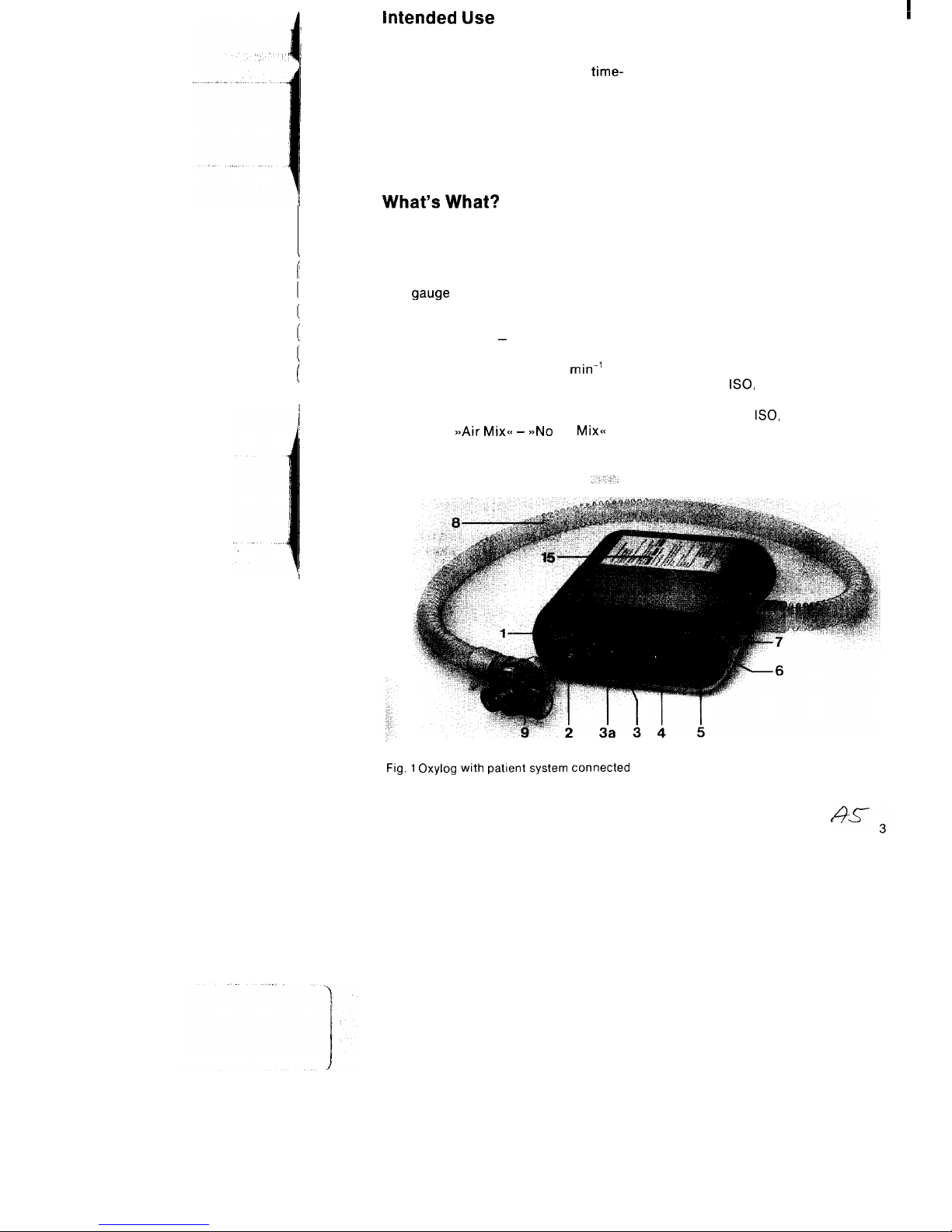
Oxylog (Figs. 1 and 2)
1 Airway pressure gauge (scale
range -10 mbar to + 80 mbar)
2
Zero adjustment of airway pressure
gauge
3
Rotary knob for setting ventilation
ratio
3a Heart symbol - adjustment aid for
ventilation during cardiopulmonary resuscitation: ratio 12
min’
4 Rotary knob for setting minute
volume (MV)
5
Pneumatic main switch I-O
6
Switch
asAir Mix<< - >>No
Air
Mix<<
for transferring patients by road or air,
for ventilation in the emergency admissions department and for transferring
patients receiving ventilation from one
department to another, e. g. from the
operating theatre to the intensive-care
ward.
7 Stud for attaching carrying strap
(also serves to secure device in
holder)
Patient system (Items 8-10)
8 Ventilation tubing
9 Non-rebreathing valve (with exter-
nal taper
ISO,
dia. 22) for breathing
mask or catheter connector (with
internal taper
ISO,
dia. 15) for tube
15
Operating instructions in brief
Fig. 1 Oxylog with patient system connected
Page 4
I
n
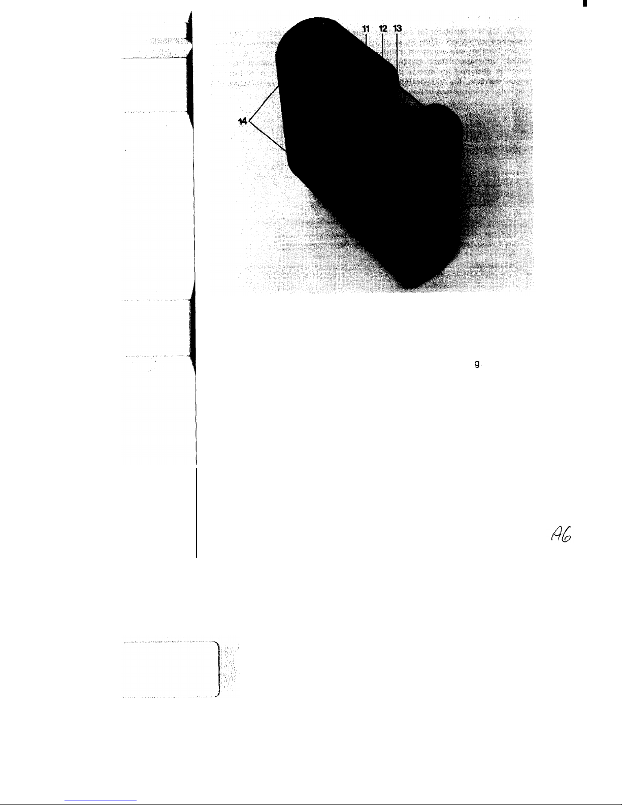
Fig. 2 Oxylog -gas inlets and outlets
11
Socket for ventilation tubing
13
Compressed-gas connection (male
12 Filter for purifying ambient air
thread M 15 x 1)
drawn in
14 Slot for alternative fastening of
carrying strap, e. g. when using
holder
4
Page 5
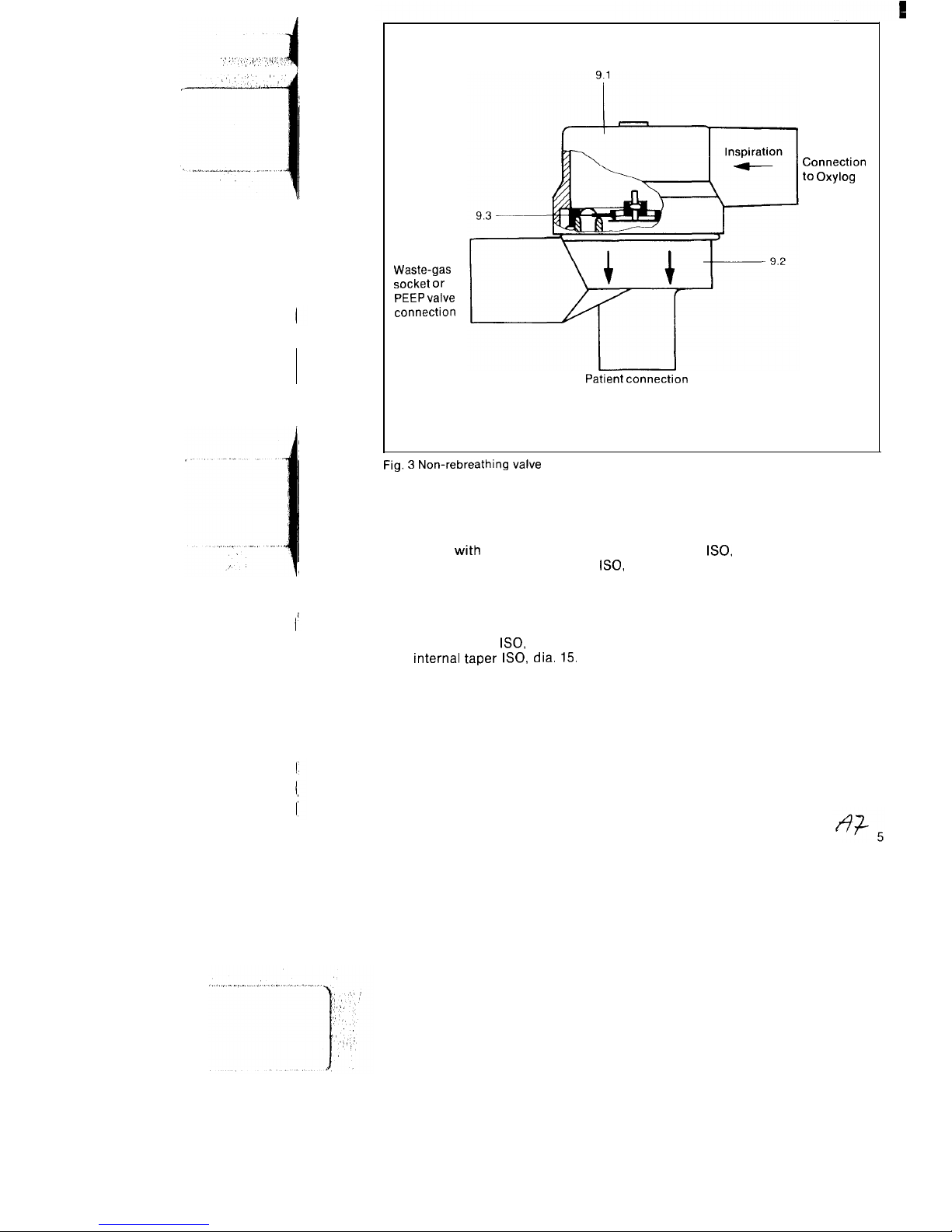
Waste-gas
socket or
PEEP valve
connection
Patient connection
Connection
to Oxylog
Fig. 3 Non-rebreathing valve
Non-rebreathing valve
(Fig. 3, Items 9.1-9.3)
9.1 Cover
with
connection for ventila-
tion tubing (external taper
ISO,
dia. 22)
9.2
Valve housing with patient connection and waste-gas socket.
The patient connection features an
external taper
ISO,
dia. 22 and an
internal taper
ISO,
dia. 15.
The
waste-gas socket has an internal
taper
ISO,
dia. 22 for connection of
a PEEP valve.
9.3 Diaphragm (complete) comprising
control diaphragm and checkvalve.
The control diaphragm and check
valve are marked yellow and red to
enable their presence and correct
installation position in the valve
housing to be checked.
Page 6
e
’ .;,,,:,,
‘;
/’
_ .-.-.-.-:i:&.. .A.!.i
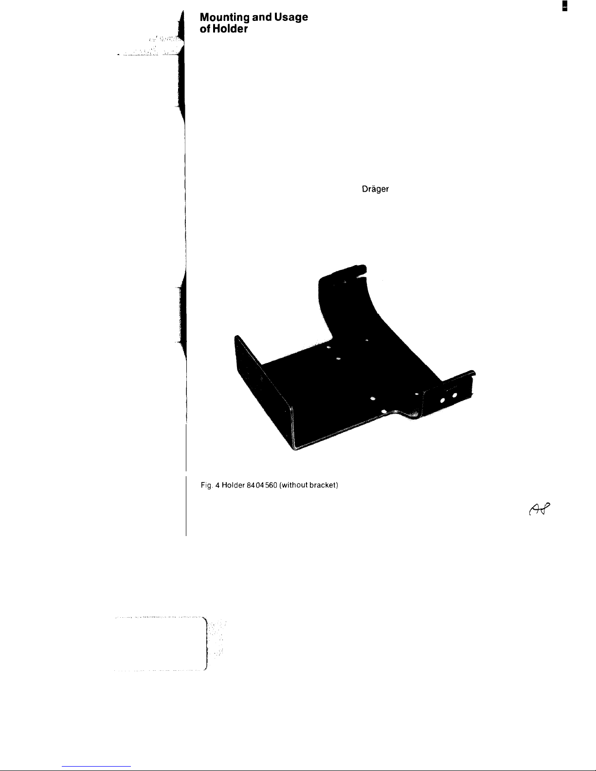
Mounting and Usage
of Holder
The Oxylog is secured in position in the
rescue vehicle by way of the holder
8404560 (Fig. 4).
The screws for attaching the basic
element are provided.
Mounting of holder
The basic element 16 is provided with
sufficient holes for the fastening screws.
At least 3 screws (with maximum
possible spacing between them) are to
be used in each case. The installation
location is arbitrary.
Insertion of Oxylog into holder
Push device into holder such that stems
of two studs 7 on housing slide into slots
Fig. 4 Holder 6404560 (without bracket)
6
16a of holder. Studs must engage in
hole in brackets 17.
Press on brackets 17 to ensure that the
device is firmly secured in position in
the holder.
The guide stud 19 secures the device on
the back. Fig. 5 illustrates the Oxylog in
position in the holder.
Removing Oxylog
Pressing open the two brackets 17
releases the studs 7 and enables the
device to be removed from the holder.
Holder with rail bracket (Fig. 6)
The holder is used for attachment to the
Drager
wall rail system (10 x 25 mm
section).
Handling is the same as for the holder
8404560.
Page 7
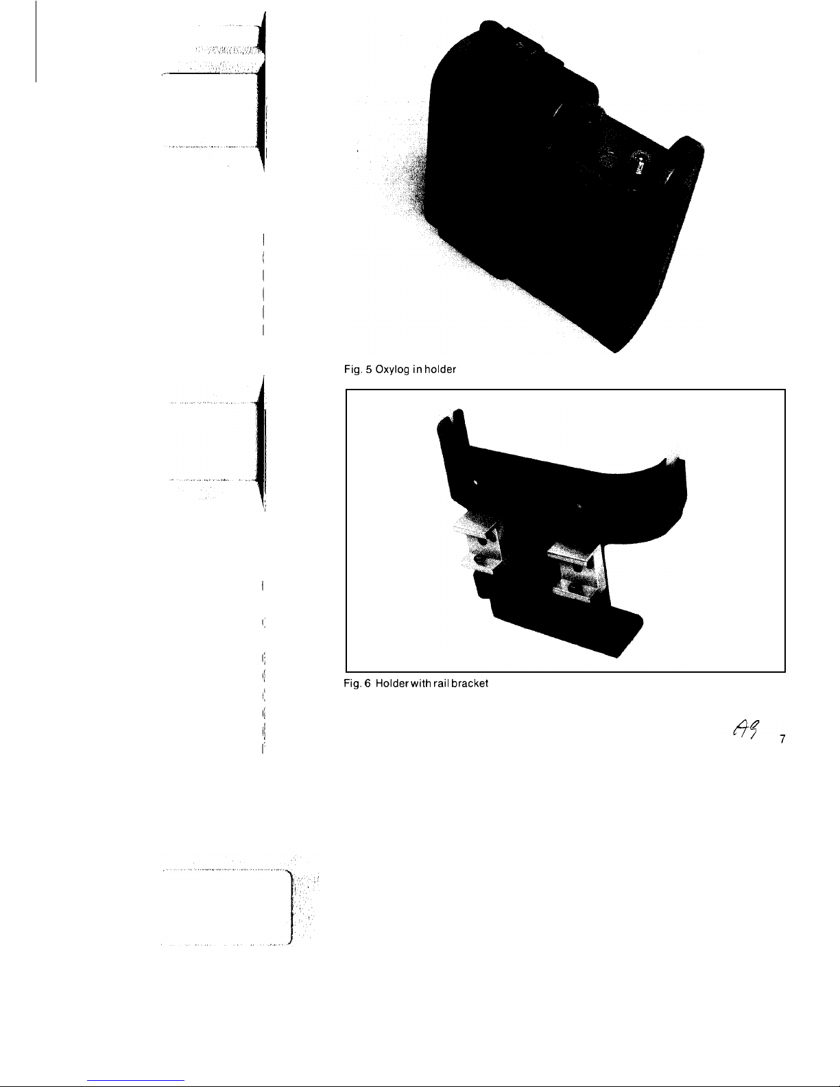
Fig. 5 Oxylog in holder
Fig. 6
Holder with
rail
bracket
Page 8
,,
--- _...___.. _.,.L._
:
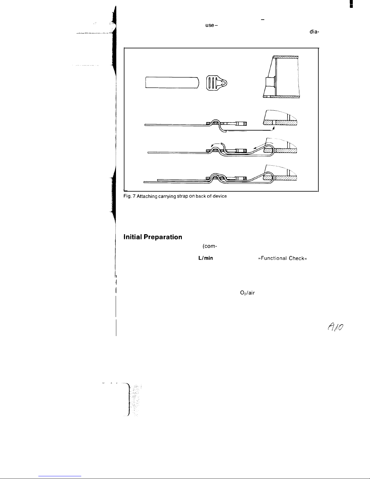
Attachment of carrying strap on back
event of constant mobile use outside the
of device
rescue vehicle - the carrying strap can
If the carrying strap is constantly in
use-
be secured in position in the slots in the
e. g. including cases where Oxylog is
Oxylog housing. See attachment
dia-
accommodated in holder and in the
gram in Fig. 7.
Fig. 7 Attaching carrying strap on back of device
Initial Preparation
An inlet pressure at the device
(com-
The functioning of the Oxylog can be
pressed-gas connection 13 in Fig. 2) of
checked with the compressed-gas
at least 2 bar at a flow rate of 60
L/min is
source (see
B>Functional Check<<
on
required for operation of the Oxylog.
page 11).
The drive sources used (central gas
’
1
supply or gas cylinder with pressure
reducer) must always comply with the
(
aboveprerequisite.
Operation from a central gas supply
Screw
OJair
connecting hose (3 m or 5
Any upstream closing or metering
m, see Order List) to device and insert
elements must be fully open!
connector into wall outlet valve.
8
,. .
”
Page 9
Operation from a gas cylinder
Screw pressure reducer to cylinder.
Check 2-6 bar delivery-pressure setting. Screw connecting hose (1.5 m or 3
m, see Order List) to device and to
pressure reducer. Fully open cylinder
valves.
Use with
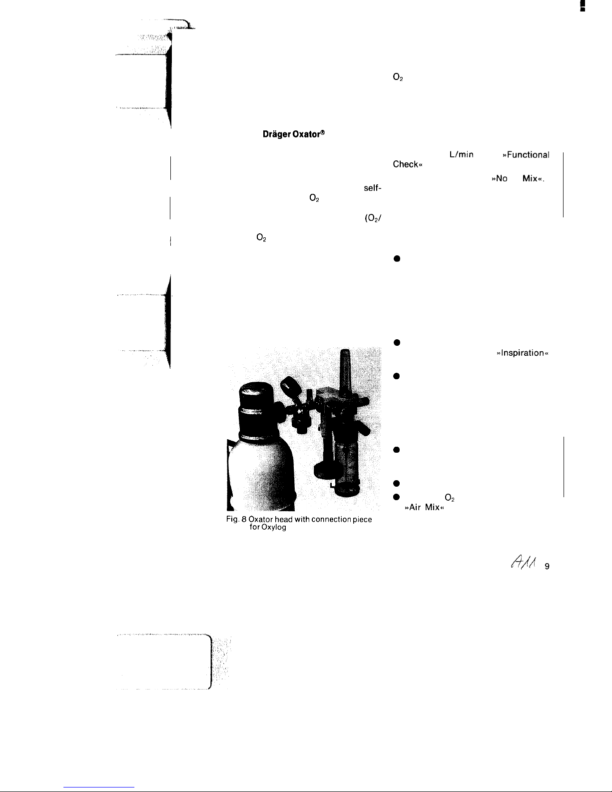
DrSger OxatoP
The connection piece 2M 19051 is
exclusively designed for use of the
Oxylog on the Oxator head (Fig. 8). This
connection piece is screwed to the
Oxator head and consists of a
self-
closing, standard
O2
coupling for
connection of the Oxylog using the
standard, gas-specific connector
(02/
air). A self-closing inlet screw connection for O2 makes it possible (in addition
to the use of cylinders) to supply the
Oxylog and the other components
connected to the Oxator head (e. g.
humidifier/nebulizer or aspiration ejector) from a central gas supply unit (see
Oxator Operating Manual).
The Oxylog may not be fed via the flow
control valves at the Oxator head!
Fig. 8 Oxator head with connection piece
for Oxylog
Use of gas blenders
.
In the case of lengthy ventilation, e. g.
during repatriation flights, low, defined
O2
concentrations may be required.
For this purpose a compressed-gas
blender can be connected upstream of
the Oxylog (see Order List).
Caution!
The inlet pressure at the Oxylog must
however be at least 2 bar at a flow rate of
approx. 60
L/min
(see
BjFunctional
Check<<
on page 11).
The switch is to be set to
a>No
Air
Mix<<.
Equipping
(Fig. 9)
0
Assemble non-rebreathing valve as
per Fig. 10. Ensure that entire
diaphragm is correctly positioned
and take particular care to ensure
that red check valve is present and
not out of shape. Screw cover to
valve housing (turn 45” in clockwise
direction).
0
Attach ventilation tubing to socket at
Oxylog as well as to
~~lnspiration~~
socket on non-rebreathing valve.
0
If use is made of an (optional)
externally adjustable pressure limiting valve (see Order List), attach this
valve first to the socket at the Oxylog
and then connect the ventilation
tubing to the socket of the pressure
limiting valve.
0
If PEEP is being applied, insert PEEP
valve (see Order List) into waste-gas
socket of non-rebreathing valve.
0
Set airway pressure gauge to zero.
0
Preselect O2 concentration
a>Air Mix<<
setting reduces drive-gas
consumption by roughly 50% as
ambient air is sucked in.
Page 10

e
a_/,,.. . . .
..,y”
,I
r ,_,. .,
.---,. . .
..-,‘.:““‘, “.‘*tT..’
,:
,‘,’ :
Wh3
Silicone tubing E 1.1 m
Silicone tubing E 1 .l m
l
Non-rebreathing valve
Ambu PEEP valve
* Only for operation with extended ventilation hose
1
Fig. 9 Oxylog with patient system
2-
Fig. 10 Individual components of non-rebreathing valve
1 Cover
2 Diaphragm
3 Valve housing
10
Page 11
e
Determination of
Compressed-Gas Supply
and Usage Period
Example:
Compressed-gas supply
O2
cylinder: 3 L
Cylinder pressure (at cylinder pressure gauge):
200 bar
Available compressed-gas supply,
200 x 3 = approx. 600 L
Usage period
Switch setting at Oxylog:
>)No
Air
Mix=
Minute volume MV: 10
L/min
Usage period
=
Compressed-gas supply
MV+l
600 L
zz
= approx. 54 min
(10 + 1)
L/min
Switching to
)jAir Mixes
reduces the gas
consumption by
50%, i.
e. the usage
period is increased to roughly 100 min.
Testing safety valve
With the same device settings and with
the patient connection sealed at the
non-rebreathing valve the max. airway
pressure should be between 50 and 80
mbar.
Testing compressed-gas supply and
minute volume
Insert catheter adapter, size 5 (M 25569)
into patient connection of
non-rebreath-
ing valve.
Read off the max. inspiration pressure
at the airway pressure gauge for the MV
settings: 7,
15,20.
MV 7
L/min
Airway pressure 4 to 8 mbar
MV 15
L/min
Airway pressure 15 to 24 mbar
MV 20
L/min
Airway pressure 28 to 38 mbar
The Oxylog should switch at regular
intervals from inspiration to expiration.
The operating prerequisites (at least 2
Functional Check
bar at 60
L/min
at Oxylog) are checked
indirectly in the MV = 20
L/min
setting.
Following device upkeep and assembly,
the Oxylog is to subjected to the
Remove catheter adapter from patient
following functional checks:
connection; the device is now ready for
operation.
Testing ventilation ratio
Device settings
Pneum. main switch
1 (ON)
MV
3
L/min
Ventilation ratio
15
mini’
Switch
,,NoAir Mix<<
Seal non-rebreathing valve at patient
connection and using stopwatch take
the time t for 10 complete cycles and
determine ventilation frequency f
f =
& min-’
The ventilation ratio of the Cxylog
should be between 13 and 17
min’.
Operational Use
The airway pressure gauge must be
observed all the time so that incorrect
ventilation can be detected in due time,
thus precluding risks for the patient!
Set ventilation ratio and minute volume
(MV) to suit patient concerned.
For rapid presetting:
The ventilation ratio and minute volume
(MV) scales each have three colour
bands for the specific patient groups
infants, children and adults.
Page 12

_ . _ .:
If both rotary knobs are set to a band of
the same colour, the following ventilation values are obtained:
Green band
for infants
(5-20 kg
body weight)
Blue band
for children
(20-40 kg
body weight)
Brown band
for adults
(as of 40 kg
body weight)
Ventilation MV
ratio
min-’
Llmin
28-35
l-3.5
18-28 3.5-7
lo-18
7-20
The switch is to be set to
a>No
Air
Mix<<
or
to
a,Air Mix<<
depending on the patient’s
requirements:
High O2 concentration required:
b>No
Air
Mixa
(and O2 drive)
In the case of a toxic atmosphere (and
respiratory standstill):
DNO
Air
Mix<<
a>No
Air
Mix<<
setting:
The drive gas, e. g.
Op,
is routed
unblended to the patient. The
ventilation ratio and MV settings
remain unchanged irrespective of
the switch setting.
Low O2 concentrations required:
BBAir Mix<<
(with 02 drive)
or compressed-air drive
Small gas supply:
a>Air Mix<<
a>Air Mix=
setting:
The drive gas
(0,
or air) is blended
with ambient air. With O2 drive and
an MV setting in excess of 7 Llmin
the percent by volume added is
approximately
50%,
i. e. the
O2
concentration is roughly 50 vol. %.
With an MV setting less than 7
Urnin
the O2 concentration in-
creases up to 80 vol.
%.
Connect non-rebreathing valve to mask
or tube.
Make sure that airways are completely
free.
Check airway pressure gauge.
In normal circumstances the inspiratory
airway pressure values should be
approximately 20 mbar.
Atypical airway pressures
In the event of an excessively high
airway pressure reading, the MV
setting should first be checked as well
als the functioning of the
non-rebreath-
ing valve.
Ensure that airways are completely
free!
High airway pressure (50-70 mbar) in
conjunction with a buzzing noise (safety
valve in device blowing out) are an
indication of incorrectly positioned
airways or a kinked tube.
If the airway pressure reading is too
low, the MV setting must likewise be
checked.
The hose connections are also to be
tested for tightness and freedom from
leaks and the non-rebreathing valve is
to be checked for proper functioning.
Ventilation ratio for cardiopulmonary
resuscitation
Within the scope of cardiopulmonary
resuscitation of adults employing a ratio
of
1:5,
it must be ensured that a
ventilatory impulse is given after every
5th cardiac compression.
Given a cardiac massage frequency of
60
min-’
this means that ventilation
must be effected with a ratio of
min-‘.
y=
12
To facilitate setting, the ventilation ratio
12
min-’
on the Oxylog is provided with
a heart symbol.
I
12
Page 13

e
Use in toxic atmosphere
The Oxylog can also be used for
controlled ventilation of injured persons in a toxic ambient atmosphere. The
switch setting
>>No
Air
Mix<<
is to be
employed for this purpose.
If the patient breathes spontaneously or
if spontaneous breathing has been
restored after resuscitation the partially
spontaneous intake of toxic ambient air
is not prevented by the Oxylog.
It is for this reason that the special
Oxylog with spontaneous breathing
device (cf. Order List) must be used.
This device facilitates spontaneous
breathing with an airway pressure 0 to
be carried out in addition to controlled
ventilation (pay attention to respective
Operating Manual).
Note
In the case of spontaneous breathing
the mask must always fit snugly, so as to
prevent the intake of toxic ambient air.
Ventilation with PEEP
(Special accessory)
Pay attention to respective Operating
Manual.
Set PEEP valve to 0 and push it onto the
waste-gas socket of the
non-rebreath-
ing valve:
Determine inspiratory airway pressure
at airway pressure gauge.
Set PEEP value:
The endinspiratory pressure increases
approximately by the set PEEP value.
Should the airway pressure rise higher
or not change its value at all, the PEEP
valve is defective and must be replaced.
Upon termination of the PEEP mode the
PEEP valve must be removed from the
valve of the airway pressure gauge.
Use of pressure limiting valve
(special accessory)
Set rotary knob at optional pressure
limiting valve (located on inspiration
socket at Oxylog) and check inspiration
pressure limited in this manner on
airway pressure gauge.
Caution!
In the case of pressure-limited ventila-
tion the set MV does not have the full
effect. It is advisable to set the pressure
limitation roughly 10 mbar in excess of
the inspiration pressure, so that the
pressure limitation only becomes effec-
tive in exceptional circumstances (e. g.
coughing).
Use of expiratory volume measurement (special accessory)
Insert hose nozzle into waste-gas
socket of non-rebreathing valve.
Connect Volumeter 3000 to silicone
tubing (1.1 m).
The Volumeter 3000 can be used to
measure both the tidal volume and the
MV (pay attention to the respective
Operating Manual).
Caution!
Expiratory volume measurement is not
possible when using the PEEP valve.
Shut-Down Actions
Set main switch to
~~0~~.
When using
compressed-gas cylinder, close cylinder valve.
Page 14

:
Option: Oxylog with demand valve to facilitate
spontaneous breathing
Pinpointed intended use
Description
Time-cycled, volume-constant ventilation
and spontaneous breathing in a toxic
at-
mosphere.
No
spontaneous breathing under
posi-
tive airway pressure (CPAP)!
-
An equipment combination of Oxylog
and demand valve switched in parallel
for supply of spontaneous breathing
-
Without Air-Mix switch
-
Non-rebreathing valve with expiratory
check valve.
The following configuration is a prerequisite for use in a toxic atmosphere:
1
2 3'
2'
14
1
Oxylog with
5
Face mask,
M25572
demand valve
size 1 small
1
2
Silicone hose E (adults)1.lm84 04 063
6 Face mask,
M 25 573
3*
Socket IS0
M 25 647
size 2, medium
4
Non-rebreathing valve
7
Face mask,
M 25 574
with check valve
8408568
size 3, large
* Only for operation with extended ventilation hose
Page 15
3
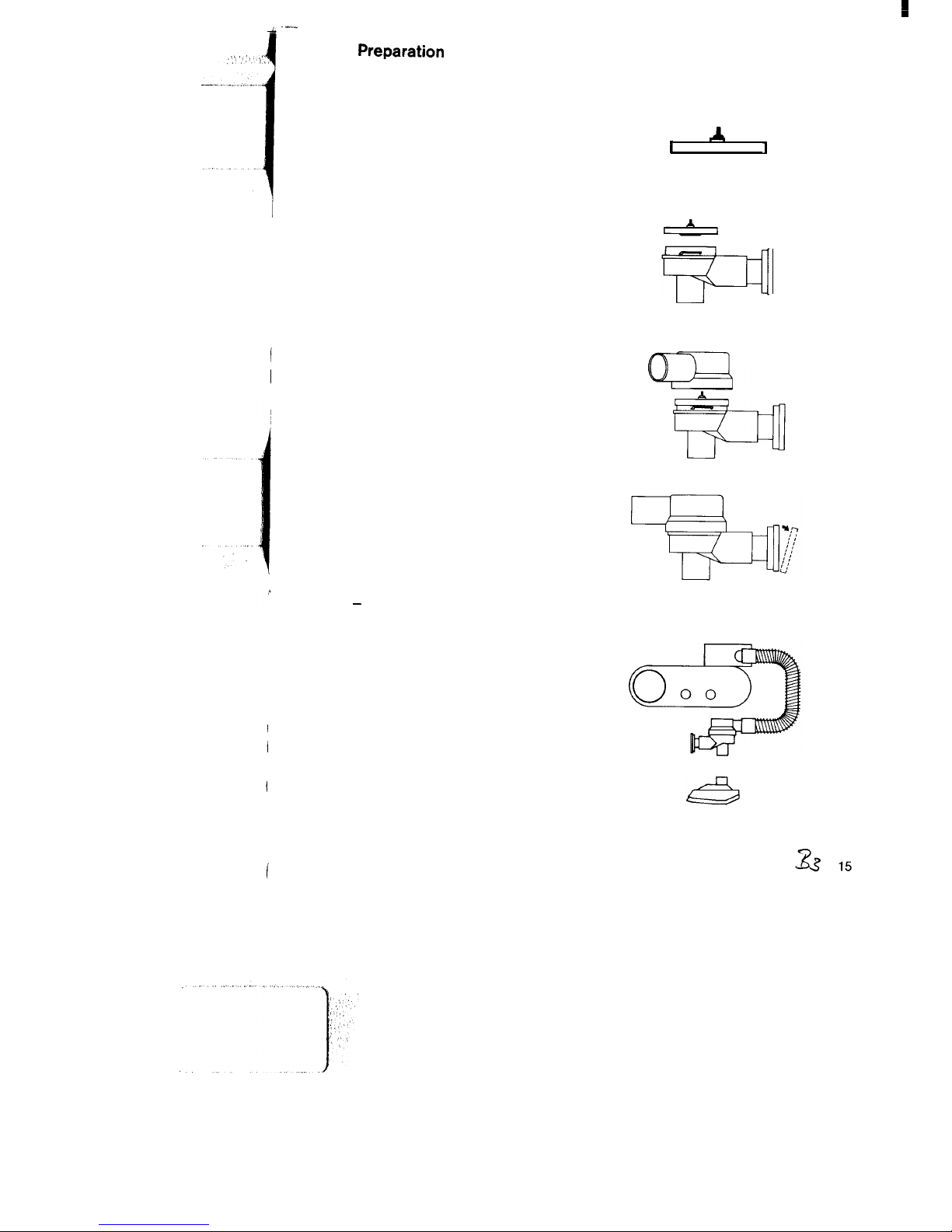
Preparation
Assembly of non-rebreathing valve:
Make sure that the red check valve is
fitted in the diaphragm and makes
even contact with the diaphragm.
Fit the diaphragm into the valve housing so that the disc of the check valve
points towards the housing.
The bulge of the diaphragm makes
even contact with the edge of the
housing.
Fit the cover by applying slight
pressure and turn clockwise by about
45”.
Make sure that the diaphragm sits
smoothly in the housing.
Pull the perforated cap at the outlet
over the edge and take it off to check
whether the rubber ring makes even
contact with the outlet.
Replace the cap by applying slight
pressure
-
until it rests in place.
Assembly of the Oxylog:
Connect Oxylog and non-rebreathing
valve with the ventilation hose.
Attach Oxylog to gas supply.
I
A
1
Page 16
Check the demand valve for
operational readiness
-
Prior to each use
Push a catheter adapter size 5 into the
patient port of the non-rebreathing
valve. Generate a suction with your
mouth:
0
Gas should begin to flow.
Stop sucking:
0
The gas flow is cut off.
Remove the catheter adapter.
Operation
Push the face mask onto the patient
port of the non-rebreathing valve and
make sure that the mask makes a
tight seal with the face.
Upon commencement of spontane-
ous breathing:
0
Set pneumatic main switch to 0.
Spontaneous breathing with posi-
tive airway pressure CPAP is not
possible!
Care
Stripping down
0
Detach ventilation hose from
Oxylog *
0
Detach non-rebreathing valve from
hose.
0
Detach mask from non-rebreathing
valve.
0
Turn cover of non-rebreathing
valve anti-clockwise by 45” and
remove.
0
Remove diaphragm from valve
housing.
Cleaning
Clean disassembled patient system
using water to which a detergent has
been added, and dry well.
Disinfection
The disinfected patient system can
be subjected to bath disinfection
e.g. using Tego 103 G (Messrs.
Th. Goldschmidt AG,
Essen)
and
observe the manufacturer’s instruc-
tions for use.
Sterilization
The valve housing of the
non-re-
breathing valve must not be sub-
jected to thermal disinfection.
The diaphragm, the cover and the
ventilation hose can be
autoclaved
at
134°C.
16
Page 17
^
.,. ,” -._.. .f
j
’ !I’
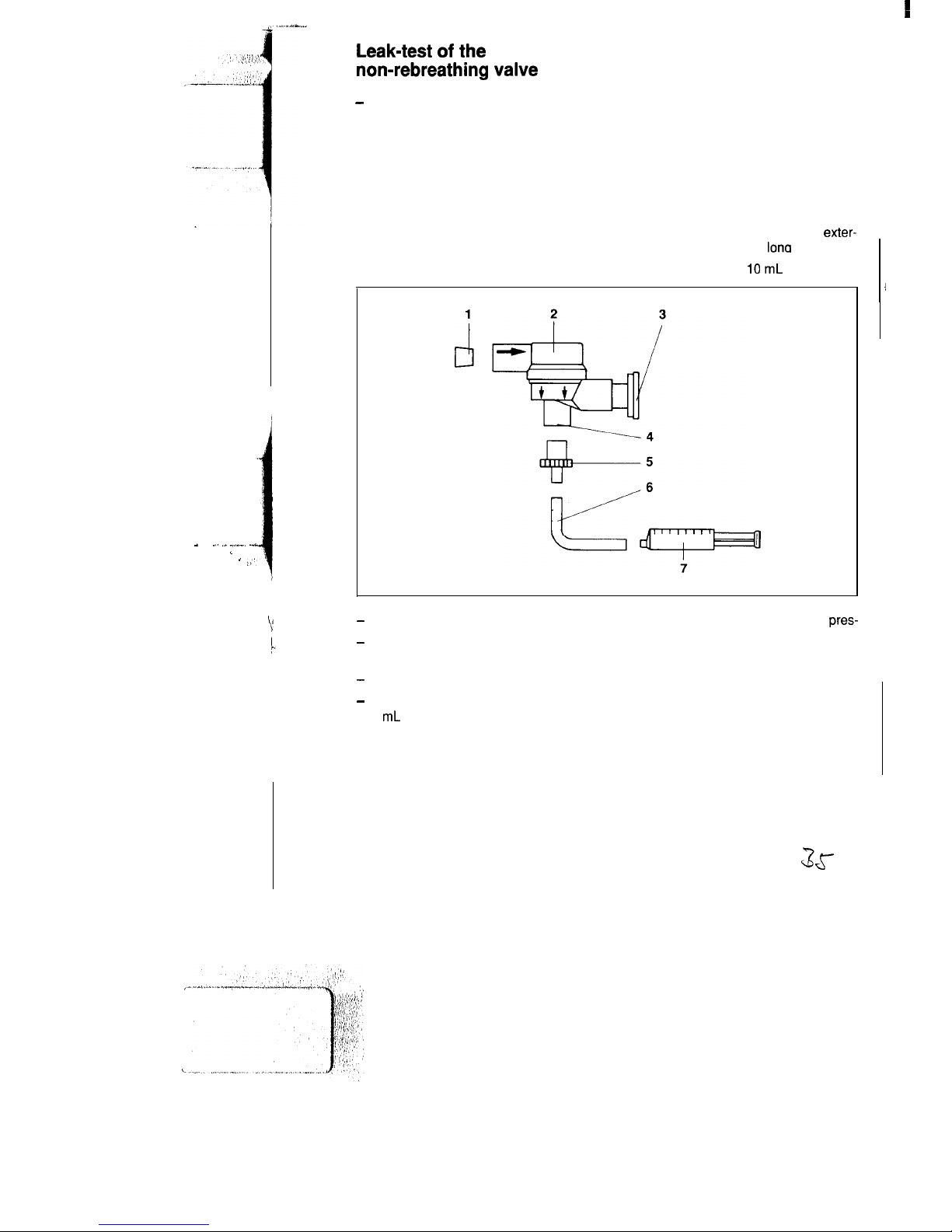
Leak-test of the
non-rebreathing valve
-
Following each assembly.
Establish test setup
1 Conical sealing plug, smallest dia.
15mm
2 Non-rebreathing valve with check
valve
4 Patient connection
5 Catheter connector, dia. 4.5 mm
6 Silicone hose, internal dia. 4 mm,
exter-
nal dia. 6 mm, 100 mm
lona
3 Cap of check valve
7 Disposable syringe, IO
mL
-
Detach cap from check valve.
-
Attach syringe together with catheter
connector.
-
Seal inspiratory port with sealing plug.
-
Using the syringe, extract a volume of
3 mL and keep plunger of syringe in this
position. By force of the negative
pres-
sure, the black diaphragm of the check
valve adapts to the shape of the valve
body.
Within 15 seconds, the diaphragm must
not
come back to its original
state.
3s
17
I
Page 18
e
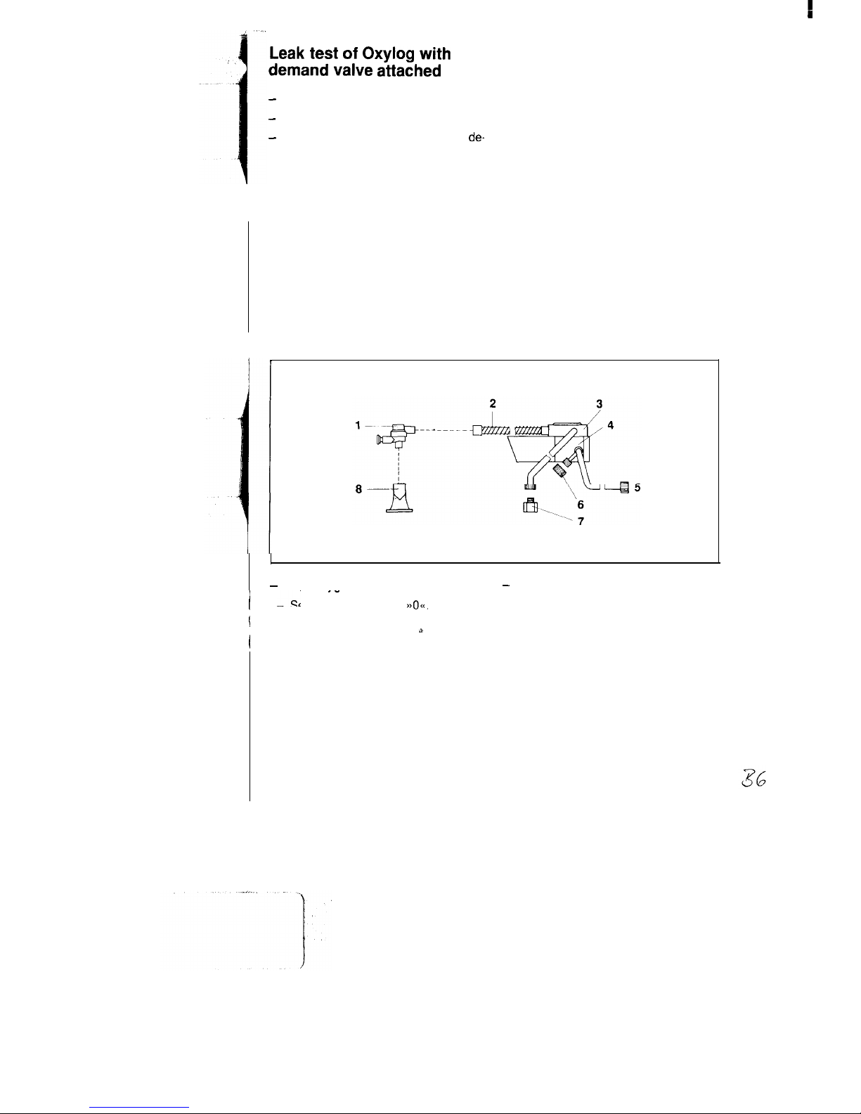
Leak test of Oxylog with
demand valve attached
-
Every 6 months.
-
Remove Oxylog from its mount.
-
Unscrew pressure-gas
line of the
de-
mand valve and seal th
e connections.
Establish test setup
Components 6, 7,
8 are
comprised in
test
set 84 10 072.
1 Non-rebreathing
valve
with
5
Pressure-gas
line,5bar
check valve
84 08
568
6
Cap nut
84 08 298
2 Ventilation hose
84 04
063
7
Screw plug
84 08 299
3 Demand valve
8
Mouthpiece
84 07 303
4 Oxylog
-
Open oxygen-cylinder valve.
-
Generate a negative pressure of about
i -.
.-
Set switch at Oxylog to
>>Oc(.
-10 mbar with your mouth.
I
Fit non-rebreathing valve to silicone
The unit is sufficiently leakproof if the
I
hose.
s
pressure change from -6 mbar to
-2 mbar takes at least 20 seconds.
18
Page 19

Care
Following termination of ventilation the
Oxylog is to be prepared for thorough
cleaning and disinfection:
Remove mask or tube from patient
connection of non-rebreathing valve.
Detach ventilation tubing from
non-
rebreathing valve and from Oxylog.
Disassemble non rebreathing valve into
its component parts (Fig. 10). Turn
cover 45” in anti-clockwise direction
with respect to valve housing (= valve
open).
Caution!
The red check valve must not be
removed from the yellow control valve!
The PEEP valve is to be disassembled
into its 3 main components.
The disassembled parts of the patient
system are to be thoroughly cleaned
either in running hot water or in a
mixture of
detergent’)/water
with sub-
sequent rinsing under running water.
Important: Do not use a hard brush for
cleaning purposes!
”
Recommended detergents are, for example,
lncldbn
Perfect
(Henkel
Co ) and
Caraform (Welgert
Co.)
The surface of the device can be
cleaned using a soft cloth impregnated
with a mixture of detergent/water.
Caution!
Do not use petrol, ether or similar
solvents for cleaning the device.
Carefully rinse Volumeter 3000 in
direction of flow
with
hot running water.
Caution!
Do not allow water to flow into drain
holes in control section.
Carefully remove residual water from
Volumeter.
All parts are to be thoroughly dried
following cleaning and rinsing.
The component parts can also be
washed in the
Drager Purfactor@,
which
automatically subjects the material to
be washed to disinfection and drying.
Disinfection in liquid disinfectant
The cleaned and dried parts of the
patient system can be disinfected in a
cold disinfectant solution.
The surface of the device can be
disinfected by wiping over it.
Caution!
Use may only be made of disinfectants
which do not attack the materials used.
Compliance with the prescribed concentrations is to be ensured. In case of
doubt consult the disinfectant manu-
facturer.
Following disinfection and drying of its
component parts, the Oxylog is to be
assembled as described under
aylnitial
Preparation<<
on Page 8 and subjected
to a functional check as described
under
a>Functional Check<<
on Page
il.
Disinfection in
Drlger Aseptor@
The cleaned and dried components of
the patient system as well as the device
itself can be disinfected in the Aseptor.
Caution!
The ventilation tubing and breathing
f
masks (silicone rubber) must not be
disinfected in the Aseptor.
Following disinfection in the Aseptor,
the device is to be assembled as
described under
a,lnitial Preparation<<
on Page 8 and subjected to a functional
check as described under
b,Functional
Check*
on Page 11.
3?-
19
Page 20
Sterilization
in steam
The valve housing of the Oxylog with demand valve to facilitate spontaneous breathing is not suitable for sterilization.
The cleaned and dried parts of the
patient system can be sterilized in
superheated steam.
The component parts of the PEEP valve
and Volumeter 3000 can be sterilized at
121 “C.
The component parts of the
non-
rebreathing valve and the ventilation
tubing can be sterilized at 134°C.
The Oxylog cannot be sterilized.
Plastic and rubber mouldings are to be
disassembled prior to sterilization.
Following sterilization in an autoclave,
the device is to be disassembled as
described under
aalnitial Preparation<<
on Page 8 and subjected to a functional
check as described under
a>Functional
Check<<
on Page 11.
20
Inspection
The device is to be inspected at regular
2 years intervals by trained personnel.
Storage
The Oxylog and its accessories are to be
kept dust-free and dry.
Permitted storage conditions:
-20°C to
+70°c
O-100%
relative humidity
600-l 200 mbar
Page 21
e
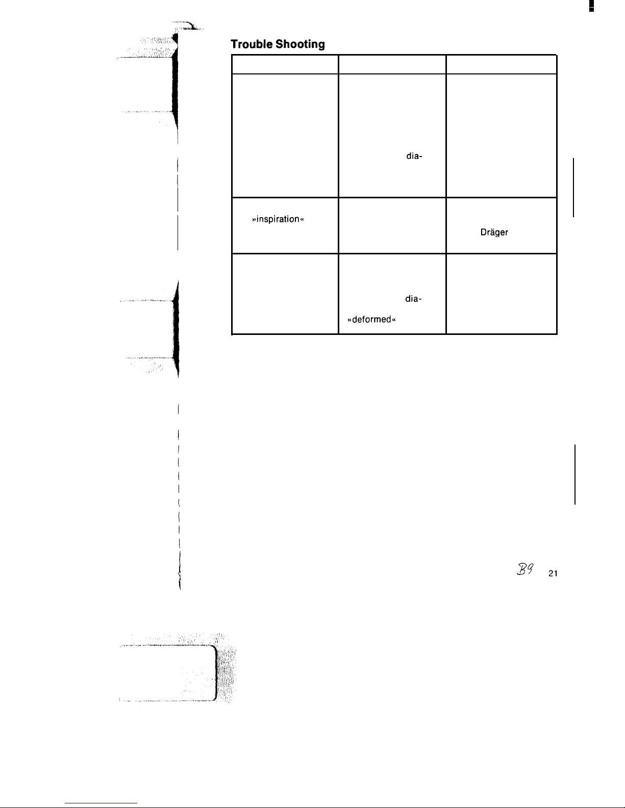
Trouble Shooting
Fault
Device does not build
up pressure
Cause
Remedy
No gas in cylinder
Immediately connect
device to another full
gas cylinder
Gas pressure at device
Establish adequate
inlet too low
supply pressure:
2-6 bar
Yellow control
dia-
Open non-rebreathing
phragm in non-rebreath- valve and assemble
ing valve deformed or
correctly
out of shape
Device comes to a halt
on
~~inspirati0r-r~~
Inadequate supply
pressure
Oxylog defective
Establish adequate
supply pressure: 2-6 bar
Notify
Drlger
Inspection Service
Patient cannot exhale or Ventilation tubing
Eliminate any kinks in
only with difficulty
kinked
tubing
Red check valve in
Open non-rebreathing
yellow control
dia-
valve and assemble
phragm missing or
correctly
~~deformed~~
Page 22
c
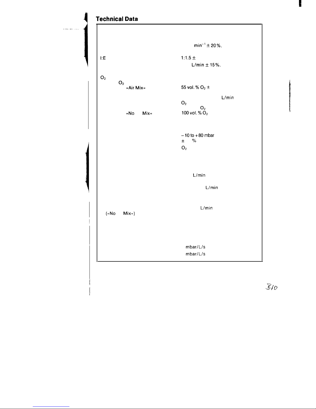
Technical Data
Principle of operation
Control
Ventilation ratio
I:E
ratio
Minute volume
Flow chopper
Time-cycled, volume-constant
10-35
min-’ + 20%,
infinitely adjustable
1:1.5 +
10%
2-20
L/min + 15%,
infinitely adjustable
O2
concentration of breathing
gas with O2 drive
Switch on
SsAir Mixa
Switch on
>bNo
Air
Mix<<
Safety valve
Opening pressure
Airway pressure reading
55vol.% 02 +
10%
(with MV greater than 7 L/min)
with MV less than 7
L/min
O2
concentration increases up to
80 vol. %
O2
100v0l.% 02
50 mbar to 80 mbar
Pressure gauge
-1Oto+80mbar
+
2.5 % full scale
Drive gas
Quality
Pressure at device inlet
O2
or air
Dry, oil-free and dust-free from a
central supply unit or from compressed-gas cylinders’.
min. 2, max. 6 bar with a flow rate
of 60
L/min
Gas consumption
Control
approx. 0.8
L/min
MV (Air Mix)
approx. 50 % of set MV
MV (No Air Mix)
approx. 100 % of set MV
Typical usage period
with 3 L cylinder/200 bar
MV = 10
L/min
(see also Page 11)
(>aNo
Air
Mix<<)
54 min
Pneumatic main switch
I-O
Patient system
Comprising silicone tubing 1.1 m
a
Non-rebreathing valve
Compressible volume
approx. 3.3 mL/mbar
Inspiration resistance
3
mbar/L/s
Expiration resistance
3
mbar/L/s
22
Page 23

Dead space
approx. 12
mL
Dimensions (W x H x D)
200 x 80 x 200
mm
Weight
approx. 2 kg
Ambient conditions during operation*:
Temperature
-5°C to
+5O”C
Humidity
O--100%
relative humidity
Ambient pressure
600-1200 mbar
Vibration
Tested in accordance with MIL STD
810 C
514.2-111
curve M (helicopter)
In toxic atmosphere
Switch to
a,No
Air Mix- setting with
controlled ventilation in the event of
respiratory standstill.
Storage conditions:
Temperature
Humidity
Ambient pressure
Caution! In the event of spontaneous
breathing possible intake of toxic
ambient atmosphere.
-23°C to
+70°c
O--100%
relative humidity
600-l 200 m bar
Materials used
Oxylog housing
Impact-resistant ABS
(Acrylonitrile-Butadiene-Styrene)
Ventilation tubing
Silicone rubber
Non-rebreathing valve
Housing
PSU (Polysulfone)
Control diaphragm
Silicone rubber
.
Non-complmce wtt,
these
reqummenls w\ll
lead to reduced
effwency
or
failure
Of
dewce functmns
Caution!
The following is to be noted when using oxygen:
All parts which carry gas must be kept free of oil and grease!
Smoking and naked flames are prohibited!
Oxylog with demand
valve
to
facilitate
spontaneous breathing
Demand valve
Opening pressure
Max. output
rci
’
Oxylog
No
apAir-Mix<<
switch
Pressure limiting valve
Non-rebreathing valve
0 to -4 mbar
100
Umin
at -7 mbar
ambient air is not sucked in
(50+30)
mbar
with additional expiratory check valve.
Page 24
, .._. ..- ,...._^,, I,
-. ,* .,.. p’”
.“*
,‘.
:
;I
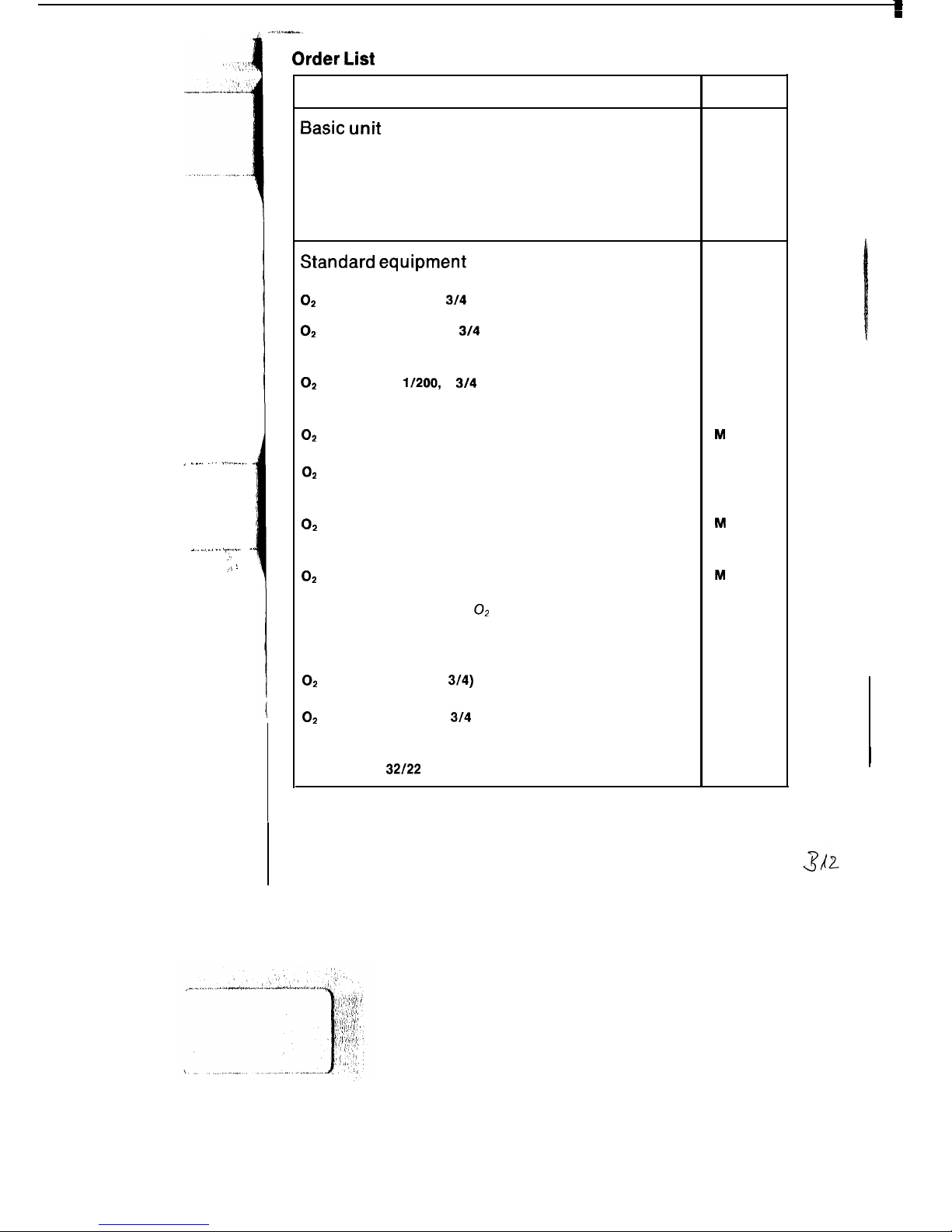
Order List
Name and description
Order No.
Basic unit
Oxylog
84 09 520
time-cycled, volume constant ventilator for controlled ventilation
in emergency medicine. Including accessories, comprising:
ventilation tubing and non-rebreathing valve.
Oxylog with spontaneous breathing
84 09 585
Standard equipment
For operation from oxygen cylinder:
O2
pressure reducer, G
314
and
D 17251
O2
cylinder AG 2.51200, G
314
straight valve, filled
or
B 03 580
O2
cylinder AG 1
l/200,
G
314
straight valve, filled
and
B 02710
OS
compressed-air connecting hose, 1.5 m
or
M
17816
O2
compressed-air connecting hose, 3 m
For operation from central supply unit
option of:
M 17617
O2
compressed-air connecting hose, 3 m
(angled plug connector)
or
M
22 494
O2
compressed-air connecting hose, 5 m
(angled plug connector)
M
22 495
For operation from portable O2 cylinder pack
Cylinder support
for two 2 L cylinders
M 23 370
Use of 2 x 2 L cylinders is possible
OS
pressure reducer (G
3/4)
and
D 20 225
O2
cylinder AG 21200, G
314
straight valve, filled
and
Spanner SW
32/22
(hexagonal)
B 02 352
M 12401
24
Page 25

----
--y
-‘(
Name and description
Order No.
Special accessories for pressure reducer D 20225:
O2
coupling hose, 0.15 m
Connection hoses between Oxylog and cylinder pack
option of:
a) screw-type both ends, option of
O2
compressed-air connecting hose, 1.5 m
or
M
23 874
M
17616
O2
compressed-air connecting hose, 3 m
b) When using O2 coupling hose M 23874,
plug-type via quick-release coupling,
thread M 15 x 1 at device end, option of:
O2
compressed-air connecting hose, 3 m
(angled plug connector)
or
M
17617
M
22 494
O2
compressed-air connecting hose, 5 m
(angled plug connector)
M
22 495
Special accessories
Silicone mask, No. 2
Silicone mask, No. 5
Holder
to secure Oxylog in mobile units
Holder with rail bracket
to attach Oxylog to wall rail
Connecting hose, 3 m
(Oxett/Oxylog)
Pressure limiting valve
adjustable from IO to 45 mbar, to be latched onto patient
connection
Volume measurement Oxylog
auxiliary means for measurement of expired volume com-
prising: Volumeter, support, silicone hose 1.1 m and 2 sockets
PEEP valve (Ambu PEEP)
adjustable from 0 to 10 mbar
Polymed 201 (gas blender)
and
21 20 194
21 20 186
84 04 560
84 05 009
M
25 879
84 05 390
84 06 995
84 07 475
D 21 800
02
compressed-air connecting hose, 1.5 m
M
17716
Continued next page
Page 26
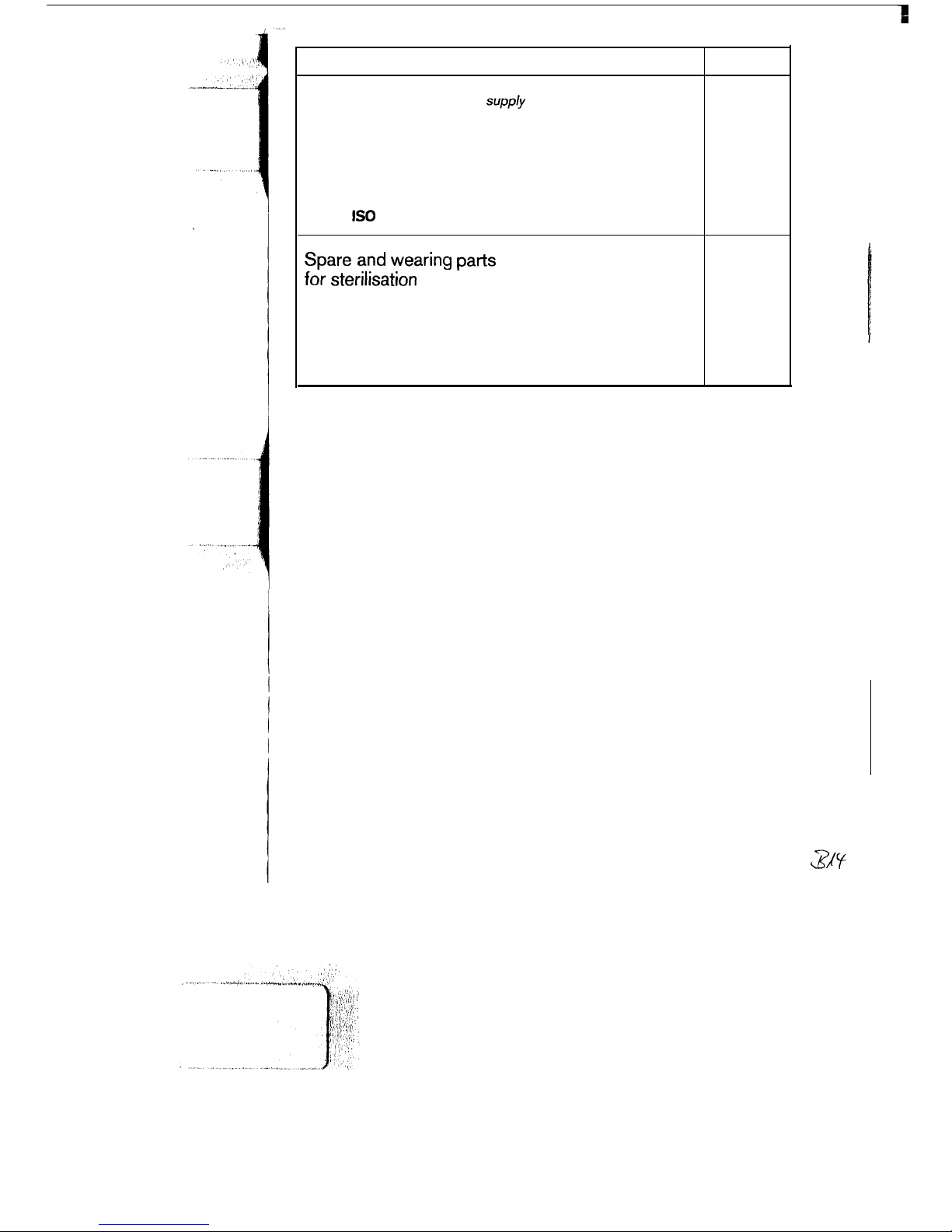
Name and description
For checking compressed-gas
supp/y
and
minute volume:
Standard connector, size 5 (stainless
steel)
For operation with extended ventilation hose:
Connection hose, silicone, 1.1 m
Socket
IS0
Spare and wearing parts
for sterilisation
Non-rebreathing valve 2
Connection hose
Silicone, 1.1 m
Carrying strap
Order No.
M
25
589
84 04
063
M
25
647
84
06
600
84
04 063
a4
04 773
26
1
Page 27
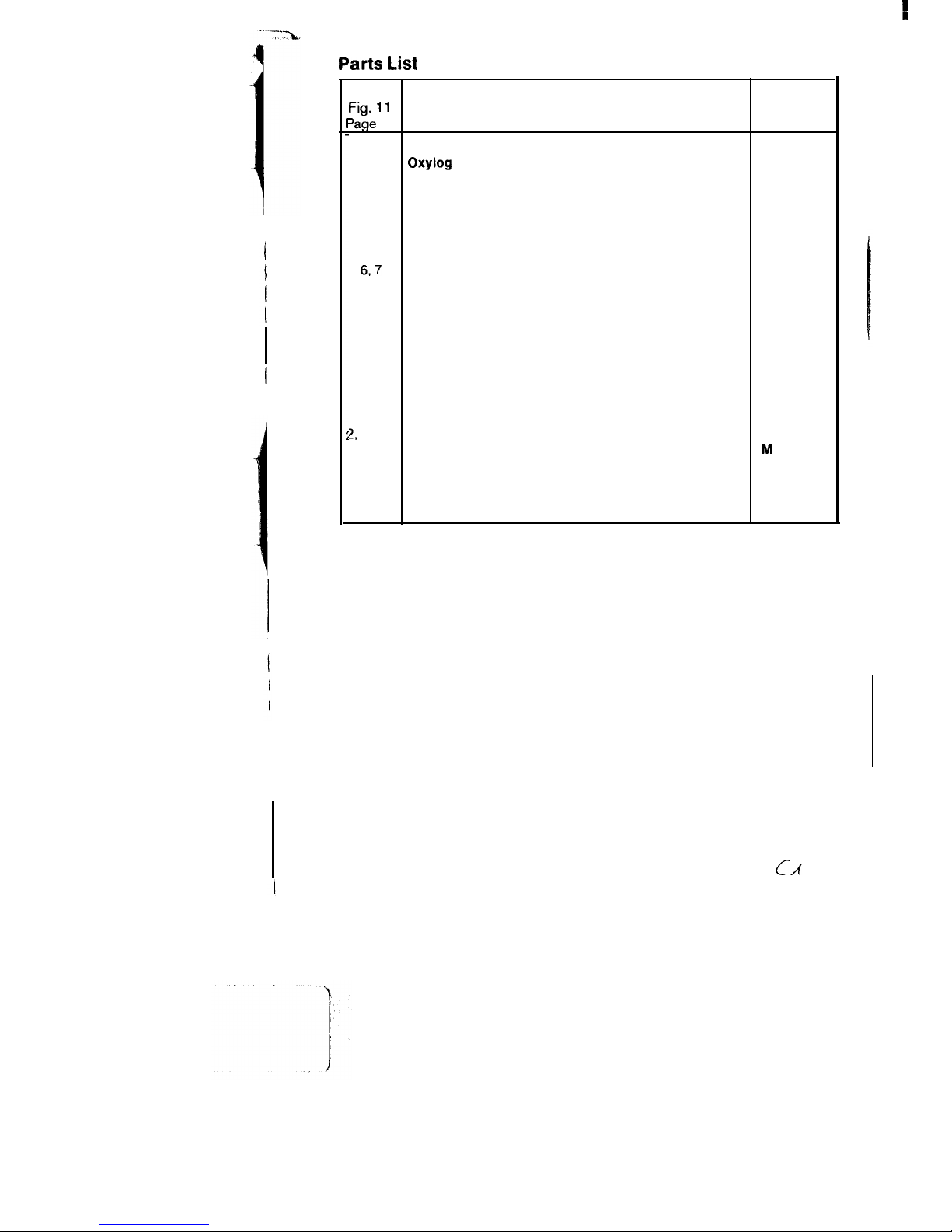
e
No. in
Fig. 11
Designation and description
Order No.
‘age
28
l-7
Oxyfog with ventilation accessories
84 09 520
1
Oxylog
84 08 500
2
Silicone tubing E 1.1 m
84 04 063
3-5
Non-rebreathing valve
84 06 600
3
Cover
84 06 585
4
Diaphragm
84 03 552
5
Valve housing
84 06 595
67
Carrying strap
84 04 773
6
Strap
84 04 078
7
Buckle
8405 179
8
Pressure limiting valve
84 05 390
9
PEEP valve (Ambu) O-10 mbar
84 07 475
10
Silicone mask, No. 2
21 20 194
10
Silicone mask, No. 5
21 20 186
12
Holder
84 04 560
13
Holder with bracket
84 05 009
2,
14-17
Voiumeter connection
84 06 995
14
Socket
M
25 647
15
Socket, complete
84 05 155
16
Volumeter 3000
2M 18250
17
Retainer
84 06 677
Parts List
c/t
27
Page 28

,
17
+!a
13+izv
-.
I
F.
I.L\
Fig.
11
Gomponent
parts (see rans
LISIJ.
*
Optional, only for operation with extended ventilation hose.
The item Nos. are not identical with the item Nos. in the other figures.
28
Page 29
These Instructions for Use apply only to
Oxylog
with Serial No.:
If no Serial No. has been filled in by
Drager these Instructions for Use are
provided for general information only and
are not intended for use with any specific
machine or device.
Drlgerwerk
Aktiengesellschaft
Germany
&
Moislinger Allee 53
-
55
D-23542 Liibeck
$3
(451)882-O
q 26807 -0
FAX
(4 51) 8 82-20 80
90 27 547 - GA 5503.1
0 Dragerwerk
AG
4th edition - November
Subject to alteration
40 e
.1993
 Loading...