

Page 1

RETURN TO THIS MANUAL'S TABLE OF CONTENTS
DrägerService
RETURN TO CD-ROM TABLE OF CONTENTS
®
Technical
Service
Manual
Part Number: S002011
Date: 20 May 2002
© 2002 Draeger Medical, Inc.
Rev: Y
Narkomed 2B
Anesthesia System
Page 2

RETURN TO THIS MANUAL'S TABLE OF CONTENTS
RETURN TO CD-ROM TABLE OF CONTENTS
Page 3

RETURN TO CD-ROM TABLE OF CONTENTS
DrägerService
®
Narkomed 2B Service Manual Table of Contents
Summary of What's New in Rev. Y
DESCRIPTION PAGE
SECTION 1:
Introduction ............................................................... 1-1
SECTION 2:
Diagnostics ............................................................... 2-1
2.1 Service Menu Screen ............................................ 2-2
SECTION 3:
Troubleshooting ............................................................ 3-1
3.1 Power Supply and Voltage Distribution .............................. 3-1
3.2 Battery ...................................................... 3-3
3.3 Troubleshooting Guides .......................................... 3-3
SECTION 4:
Replacement Procedures ..................................................... 4-1
4.1 Cylinder Yoke Assemblies ........................................ 4-2
4.2 Cylinder Pressure Regulators ...................................... 4-5
4.3 Cylinder Cutoff Valves (Canada) ................................... 4-8
4.4 Cylinder and Pipeline Pressure Gauges ............................. 4-11
4.5 Flowmeters .................................................. 4-15
4.6 Flow Control Valves ............................................ 4-19
4.7 Oxygen Supply Pressure Failure Protection Device ..................... 4-22
4.8 Oxygen Supply Pressure Alarm Switch (earlier machines) ............... 4-25
4.9 Oxygen Supply Pressure Alarm Whistle (Canada) ..................... 4-28
4.10 Oxygen Ratio Monitor/Controller .................................. 4-30
4.11 Oxygen Ratio Controller (later machines) ............................ 4-34
4.12 Vaporizers ................................................... 4-37
4.13 O
4.14 AV-E Ventilator Controller Assembly ............................... 4-44
4.15 AV-E Ventilator Solenoid Valve ................................... 4-47
4.16 AV-2 Ventilator Controller Assembly ............................... 4-50
4.17 Convenience Outlet AC Power Filter ............................... 4-53
4.18 AV-E Inspiratory Flow Regulator .................................. 4-56
4.19 Ventilator Bellows Valve and Guide Assembly (AV-E Ventilator) .......... 4-59
4.20 Ventilator Bellows Valve and Guide Asm w/Press Lim Ctrl (AV-2) ......... 4-69
4.21 Alarm Channel (without oxygen supply pressure alarm switch) ........... 4-73
4.22 Alarm Channel and Oxygen Supply Pressure Alarm Switch .............. 4-76
4.23 Caster ...................................................... 4-80
4.24 Battery ..................................................... 4-83
4.25 Power Supply ................................................. 4-86
4.26 Processor Assembly ............................................ 4-89
4.27 CRT Assemblies ............................................... 4-92
4.28 Keypads ..................................................... 4-96
4.29 SPIROMED Respiratory Volume Sensor ............................. 4-99
Flush Valve ................................................ 4-40
2
Rev. T
i
Page 4

RETURN TO THIS MANUAL'S TABLE OF CONTENTS
RETURN TO CD-ROM TABLE OF CONTENTS
CONTENTS (continued) NM2B
DESCRIPTION PAGE
4.30 Oxygen Sensor .......................................... 4-101
4.31 Manual Sphygmomanometer ............................... 4-103
4.32 Auxiliary Oxygen Flowmeter ............................... 4-105
4.33 PEEP Valve Magnet Assembly Replacement ................... 4-107
SECTION 5:
Adjustment and Calibration Procedures ...................................5-1
5.1 Cylinder Pressure Regulator Adjustment (except CO
5.1A CO
Cylinder Pressure Regulator Adjustment ....................5-4
2
) ..............5-2
2
5.2 Oxygen Supply Pressure Alarm Switch Adjustment (earlier machines) . 5-5
5.3 Oxygen Supply Pressure Alarm Switch Adjustment (later machines
with switch on alarm channel) ................ 5-8
5.4 Oxygen Ratio Monitor/Controller (ORMC) Adjustment ............. 5-11
5.5 Oxygen Ratio Controller (ORC) Adjustment ..................... 5-15
5.5A Low Flow Oxygen Ratio Controller (ORC) Adjustment ............5-17A
5.6 Oxygen Sensor Calibration .................................. 5-18
5.7 Breathing Pressure Monitor Calibration ........................ 5-21
5.8 Vaporizer Interlock Adjustment .............................. 5-23
SECTION 6:
PMS Procedure ......................................................6-1
6.1 Electrical Safety ........................................... 6-2
6.2 Self-Diagnostics ...........................................6-4
6.3 Battery Circuit ............................................ 6-5
6.4 Configuration ............................................. 6-5
6.5 Service Data .............................................6-6
6.6 Calibrations ..............................................6-7
6.7A Scavenger, A/C ............................................6-8
6.7B Scavenger, Open Reservoir ...................................6-9
6.7C Scavenger Interface .......................................6-11
6.7D Suction Regulator ........................................ 6-13
6.8 Breathing System ........................................ 6-14
6.9 Manual Sphygmomanometer ................................ 6-22
6.10 Vapor Exclusion System .................................... 6-23
6.11 Yokes & Gauges .......................................... 6-24
6.12 High Pressure Regulator ................................... 6-26
6.13 High Pressure Leak ....................................... 6-28
6.14 Oxygen Supply Failure Protection ............................ 6-31
6.15 Flowmeters ............................................. 6-35
6.16 O
Med................................................. 6-38
2
6.17 Oxygen Concentrations .................................... 6-40
6.18 Auxiliary Oxygen flowmeter ................................. 6-43
6.19A Oxygen Ratio Controller .................................... 6-44
6.19B Oxygen Ratio Monitor Controller ............................. 6-45
6.20 Baromed ............................................... 6-47
6.21 Ventilator .............................................. 6-49
6.22 Bellows Drive Gas Leak: Adult .............................. 6-50
6.23 Spiromed ............................................... 6-51
ii
Rev. W
Page 5

RETURN TO THIS MANUAL'S TABLE OF CONTENTS
RETURN TO CD-ROM TABLE OF CONTENTS
NM2B CONTENTS (continued)
DESCRIPTION PAGE
6.24 Manual Sphygmomanometer ................................ 6-39
6.24A Bellows: Adult ........................................... 6-53
6.24B Ventilator Relief Valve: Adult ............................... 6-53
6.25A Bellows: Pediatric External .................................6-54
6.25B Bellows: Pediatric Internal .................................. 6-56
6.26 Trace & Trend ........................................... 6-58
6.27 Pressure Limit Controller .................................. 6-58
6.28 Bellows Peep Valve .......................................6-59
6.29 Audio Silence ............................................ 6-59
6.30 Oxygen Flush Valve ....................................... 6-60
6.31 Final Tests .............................................. 6-61
SECTION 7:
Software Update Procedure .............................................7-1
SECTION 8:
Spare and Replacement Parts
ASSEMBLY/PART PAGE
Monitor Chassis, Front Bezel, Power Supply, Processor Assembly, CRT Assemblies ...... 8-2, 8-3
AV-E Ventilator Box Assembly, Incl. Controller ................................. 8-4, 8-5
AV-2 Ventilator Controller Assembly ......................................... 8-6, 8-7
AV-E Ventilator Bellows Valve & Guide Assembly ............................... 8-8, 8-9
AV-2 Valve Case and Guide Assembly, Press. Limit Control, Bellows Assembly. ...... 8-10, 8-11
Bellows valve assembly details ......................................... 8-11A, 8-11B
Pipeline Inlet Fittings .................................................. 8-12, 8-13
Failsafe Assemblies, Minimum O2Flow Valve Assembly ........................ 8-14, 8-15
Gas Selector Switch and Valves ........................................... 8-16, 8-17
Vapor Exclusion System .............................................. 8-17A, 8-17B
ORMC (Earlier Config.) O2Alarm Switch, Alarm Channel, Alarm Whistle ........... 8-18, 8-19
ORC Assembly ........................................................ 8-20, 8-21
Alarm Channel Assembly with O2Alarm Switch (Later Configurations) ............. 8-22, 8-23
Flowmeter Shields, Knobs, Labels, Gauges .................................. 8-24, 8-25
Flow Tubes, Restrictor Assemblies, Flow Control Valve ......................... 8-26, 8-27
Cyl. Regulator Assemblies, O2Flush Valve and related parts ..................... 8-28, 8-29
CSA Items: Relief Valve, Cylinder Cutoff Valves .............................. 8-30, 8-31
Canada Fresh Gas Outlet ............................................. 8-31A, 8-31B
Cylinder Yokes, Common Parts, Labels ..................................... 8-32, 8-33
Sensor Interface Panel Asms., AC Power, Casters ............................. 8-34, 8-35
Absorber Assembly, Breathing Pressure Hoses, Oxygen Sensor ................... 8-36, 8-37
Ultrasonic Flow Sensor ............................................... 8-37A, 8-37B
Ultrasonic Flow Sensor Mounting Bracket .................................8-37C, 8-37D
Man/Auto Selector Valve ................................................ 8-38, 8-39
Man/Auto Selector Valve (Later Design) .................................... 8-40, 8-41
Auxiliary O2Flowmeter Assembly ......................................... 8-42, 8-43
Open Reservoir Scavenger ............................................... 8-44, 8-45
Open Reservior Scavenger, old style ....................................... 8-46, 8-47
A/C Scavenger ........................................................ 8-48, 8-49
Suction Scavenger ..................................................... 8-50, 8-51
Rev. X
iii
Page 6

NARKOMED 2B ANESTHESIA SYSTEM
R
Y
A
RETURN TO THIS MANUAL'S TABLE OF CONTENTS
RETURN TO CD-ROM TABLE OF CONTENTS
BOOM
RM
ALARM
DISPLAY
SYSTEM
CONTROL
KEYS
DATA DISPLA
MONITO
CONTROL
KEYS
MANUAL
SPHYGMOMANOMETER
(OPTIONAL)
BREATHING
SYSTEM SENSOR
INTERFACE PANEL
SV20001
1-0 Rev. F
Page 7

RETURN TO THIS MANUAL'S TABLE OF CONTENTS
RETURN TO CD-ROM TABLE OF CONTENTS
NM2B INTRODUCTION
1.0 Recommendations
Because of the sophisticated nature of Draeger Medical, Inc. anesthesia equipment and its critical
importance in the operating room setting, it is highly recommended that only appropriately
trained and experienced professionals be permitted to service and maintain this equipment.
Please contact DrägerService® at (800) 543-5047 for service of this equipment.
Draeger Medical, Inc. also recommends that its anesthesia equipment be serviced at three-month
intervals. Periodic Manufacturer’sService Agreementsare availablefor equipmentmanufactured
by Draeger Medical, Inc. For further information concerning these agreements, please contact us
at (800) 543-5047.
Draeger Medical, Inc. products/material in need of factory repair shall be sent to:
DrägerService
3124 Commerce Drive
Telford, PA 18969
(Include RMA Number)
HOW TO USE THIS MANUAL
The manual is divided into several sections. The DIAGNOSTICS section describes self-test and
service diagnostics for checking the system functions. An understanding of the on-board service
capabilities is necessary before any attempt is made to troubleshoot the unit. The
TROUBLESHOOTING section lists error codes and provides troubleshooting guides to assist the
TSR in locating the source of a problem. The REPLACEMENT PROCEDURES section contains
instructions for removal and replacement of the assemblies that are considered field-replaceable.
The ADJUSTMENT AND CALIBRATION PROCEDURES section contains the field procedures
needed to restore original system specifications. The Periodic Manufacturer’s Service (PMS)
PROCEDURE section outlines the steps required to verify the electrical, mechanical and
pneumatic safety of the unit and also identifies components requiring periodic replacement.
GENERAL TROUBLESHOOTING GUIDELINES
Troubleshooting the Narkomed 2B should always begin by communicating with those who
observedor experienced a problem with the unit.This mayeliminate unnecessary troubleshooting
steps. Once a general problem is identified, refer to the troubleshooting flow charts in Section 3
to determine the proper corrective action to be taken.
After a component has been replaced, verify that the unit is operating properly by running the
appropriate diagnostic procedure. The PMS PROCEDURE in Section 6 must also be performed
after any component has been replaced.
The general arrangement of the Narkomed 2B Anesthesia System is shown on the opposite page.
WARNINGS are used in this manual before procedures which if not performed correctly could
result in personal injury.
CAUTIONS are used in this manual to alert service personnel to the possibility of damage to the
equipment if a procedure is not performed correctly.
Rev. K
1-1
Page 8

RETURN TO THIS MANUAL'S TABLE OF CONTENTS
RETURN TO CD-ROM TABLE OF CONTENTS
INTRODUCTION NM2B
Copyright
Copyright © 2001 by Draeger Medical, Inc. All rights reserved. No part of this publication
may be reproduced, transmitted, transcribed, or stored in a retrieval system in any form or
by any means, electronic or mechanical, including photocopying and recording, without the
written permission of Draeger Medical, Inc.
Trademark Notices
CliniDAS, Datagrip, NAD Information Systems, NAD Logo, Narkomed, O.R. Data Manager,
O.R. Link, ORM, PC Prep/View, Quality Service For Life, Vigilance Audit, Vitalert, Vitalink
and Narkomed GS are registered trademarks of Draeger Medical, Inc. All other products or
name brands are trademarks of their respective owners.
Disclaimer
The content of this manual is furnished for informational use only and is subject to change
without notice. Draeger Medical, Inc. assumes no responsibility or liability for any errors or
inaccuracies that may appear in this manual.
1-2
Rev. N
Page 9
RETURN TO THIS MANUAL'S TABLE OF CONTENTS
RETURN TO CD-ROM TABLE OF CONTENTS
NM2B DIAGNOSTICS
2.0 DIAGNOSTICS
The Narkomed 2B contains a diagnostic system that monitors certain system functions and
records their operational status. A series of tests is performed when the system is powered
up and the results are displayed on the diagnostics screen shown in Figure 2-1. Further
diagnostic functions are available through service screens that can be called up by a TSR at
the display panel. The following paragraphs provide a description of each service screen that
can be accessed through system control keys on the display panel. If no display is present
upon system power-up, refer to Section 3 of this manual for troubleshooting assistance.
NARKOMED 2B
VIDEO TEST PASS VERSION 2.02 DIAGNOSTICS
FIRMWARE TEST PASS COPYRIGHT, NAD INC. 1987-89
MEMORY TEST PASS
TIMERS TEST PASS
ANALOG TEST PASS
AUDIO TEST - PRIMARY PASS
- BACKUP PASS
SERIAL I/O TEST PASS
CLOCK TEST PASS
BACKUP MEMORY TEST PASS
AC POWER TEST PASS
RESERVE POWER TEST PASS
FUNCTIONAL
Figure 2-1: POWER-UP DIAGNOSTICS SCREEN
TRACE
TREND
2-1
Page 10
RETURN TO THIS MANUAL'S TABLE OF CONTENTS
RETURN TO CD-ROM TABLE OF CONTENTS
DIAGNOSTICS (continued) NM2B
2.1 Service Menu Screen
To access the Service Menu Screen, press and hold the CONFIG key, and
(while holding the CONFIG key) simultaneously press the 21% and APNEA
ALARM DISABLE keys. These keys are located on the monitor control key
panel. The Service Menu Screen appears as shown in Figure 2-2. Access to the
other service functions is gained through the keys to the right of the service
screen which temporarily function according to their corresponding on-screen
labels.
SERVICE MENU DIAGNOSTICS
CALIBRATION
EXIT
Figure 2-2: SERVICE MENU SCREEN
TRACE
TREND
2-2
Rev. A
Page 11
RETURN TO THIS MANUAL'S TABLE OF CONTENTS
RETURN TO CD-ROM TABLE OF CONTENTS
NM2B DIAGNOSTICS (continued)
2.1.1 Diagnostics Menu Screen
Pressing the DIAGNOSTICS key on the Service Menu Screen brings up
the Diagnostics Menu Screen. Figure 2-3 shows a typical Diagnostics
menu which displays the last service date and an error log. To reset the
last service date to the current date, press the RESET DATE key.
NOTE: The RESET DATE key also clears all stored error codes,
so the date should not be reset until the indicated
problems are resolved. If the processor assembly must be
replaced, the original assembly should be returned to the
NAD Technical Service Department with all of its stored
error codes.
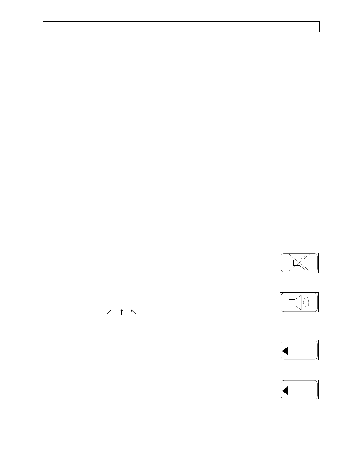
Each line in the Error Log is displayed as three groups of hexadecimal
characters, with each group having a left and right character (see
Figure 2-3). Tables 2-1, 2-2 and 2-3 on the following pages list the
possible errors that correspond to the displayed characters in each
group.
DIAGNOSTICS MENU KEY TEST
LAST SERVICE DATE 14-JUN-91
ERROR LOG 00
Group 1 Group 2 Group 3
00 40 RESET DATE
EXIT
Figure 2-3: DIAGNOSTICS MENU SCREEN
TRACE
TREND
Rev. L
2-3
Page 12

RETURN TO THIS MANUAL'S TABLE OF CONTENTS
RETURN TO CD-ROM TABLE OF CONTENTS
DIAGNOSTICS (continued) NM2B
Table 2-1: NARKOMED 2B ERROR CODES, GROUP 1
Left
Char. Error(s)
0 No Error 0 No Error
1 System memory fail (checkerboard test) 1 CRT controller fail (readback test)
2 System memory fail (ROM compare test) 2 CRT memory fail (checkerboard test)
3 System memory fail (checkerboard test)
System memory fail (ROM compare test)
4 CTC fail (timer function test) 4 CRT memory fail (ROM compare test)
5 CTC fail (timer function test)
System memory fail (checkerboard test)
6 CTC fail (timer function test)
System memory fail (ROM compare test)
7 CTC fail (timer function test)
System memory fail (ROM compare test)
System memory fail (checkerboard test)
8 CTC fail (interrupt logic test) 8 ROM fail (firmware CRT test)
9 CTC fail (interrupt logic test)
System memory fail (checkerboard test)
Right
Char. Error(s)
3 CRT controller fail (readback test)
CRT memory fail (checkerboard test)
5 CRT memory fail (ROM compare test)
CRT controller fail (readback test)
6 CRT memory fail (ROM compare test)
CRT memory fail (checkerboard test)
7 CRT memory fail (ROM compare test)
CRT memory fail (checkerboard test)
CRT controller fail (readback test)
9 ROM fail (firmware CRT test)
CRT controller fail (readback test)
A CTC fail (interrupt logic test)
System memory fail (ROM compare test)
B CTC fail (interrupt logic test)
System memory fail (ROM compare test)
System memory fail (checkerboard test)
C CTC fail (interrupt logic test)
CTC fail (timer function test)
D CTC fail (interrupt logic test)
CTC fail (timer function test)
System memory fail (checkerboard test)
E CTC fail (timer function test)
CTC fail (interrupt logic test)
System memory fail (ROM compare test)
F CTC fail (interrupt logic test)
CTC fail (timer function test)
System memory fail (ROM compare test)
System memory fail (checkerboard test)
A ROM fail (firmware CRT test)
CRT memory fail (checkerboard test)
B ROM fail (firmware CRT test)
CRT memory fail (checkerboard test)
CRT controller fail (readback test)
C ROM fail (firmware CRT test)
CRT memory fail (ROM compare test)
D ROM fail (firmware CRT test)
CRT memory fail (ROM compare test)
CRT controller fail (readback test)
E ROM fail (firmware CRT test)
CRT memory fail (ROM compare test)
CRT memory fail (checkerboard test)
F ROM fail (firmware CRT test)
CRT memory fail (ROM compare test)
CRT memory fail (checkerboard test)
CRT controller fail (readback test)
2-4
Rev. L
Page 13

RETURN TO THIS MANUAL'S TABLE OF CONTENTS
RETURN TO CD-ROM TABLE OF CONTENTS
NM2B DIAGNOSTICS (continued)
Table 2-2: NARKOMED 2B ERROR CODES, GROUP 2
Left
Char. Error(s)
0 No Error 0 No Error
1 Backup audio fail (sound generation test) 1 A/D conv. fail (analog V out of range)
2 Serial port B fail (channel A on UART) 2 Primary audio fail (speaker test)
3 Backup audio fail (sound generation test)
Serial port B fail (channel A on UART)
4 Serial port A fail (channel B on UART) 4 Primary audio fail (sound gen. test)
5 Serial port A fail (channel B on UART)
Backup audio fail (sound generation test)
6 Serial port A fail (channel B on UART)
Serial port B fail (channel A on UART)
7 Serial port A fail (channel B on UART)
Serial port B fail (channel A on UART)
Backup audio fail (sound generation test)
8 Clock fail (cannot read) 8 Backup audio fail (speaker test)
9 Clock fail (cannot read)
Backup audio fail (sound generation test)
Right
Char. Error(s)
3 A/D conv. fail (analog V out of range)
Primary audio fail (speaker test)
5 Primary audio fail (sound gen. test)
A/D conv. fail (analog V out of range)
6 Primary audio fail (sound gen. test)
Primary audio fail (speaker test)
7 Primary audio fail (sound gen. test)
Primary audio fail (speaker test)
A/D conv. fail (analog V out of range)
9 Backup audio fail (speaker test)
A/D conv. fail (analog V out of range)
A Clock fail (cannot read)
Serial port B fail (channel A on UART)
B Clock fail (cannot read)
Serial port B fail (channel A on UART)
Backup audio fail (sound generation test)
C Clock fail (cannot read)
Serial port A fail (channel B on UART)
D Clock fail (cannot read)
Serial port A fail (channel B on UART)
Backup audio fail (sound generation test)
E Clock fail (cannot read)
Serial port A fail (channel B on UART)
Serial port B fail (channel A on UART)
F Clock fail (cannot read)
Serial port A fail (channel B on UART)
Serial port B fail (channel A on UART)
Backup audio fail (sound generation test)
A Backup audio fail (speaker test)
Primary audio fail (speaker test)
B Backup audio fail (speaker test)
Primary audio fail (speaker test)
A/D conv. fail (analog V out of range)
C Backup audio fail (speaker test)
Primary audio fail (sound gen. test)
D Backup audio fail (speaker test)
Primary audio fail (sound gen. test)
A/D conv. fail (analog V out of range)
E Backup audio fail (speaker test)
Primary audio fail (sound gen. test)
Primary audio fail (speaker test)
F Backup audio fail (speaker test)
Primary audio fail (sound gen. test)
Primary audio fail (speaker test)
A/D conv. fail (analog V out of range)
Rev. L
2-5
Page 14

RETURN TO THIS MANUAL'S TABLE OF CONTENTS
RETURN TO CD-ROM TABLE OF CONTENTS
DIAGNOSTICS (continued) NM2B
Table 2-3: NARKOMED 2B ERROR CODES, GROUP 3
Left
Char. Error(s)
0 No Error 0 No Error
1 Backup memory fail (ROM compare test) 1 Clock fail (write/readback test)
2 Backup memory fail (array recall test) 2 Clock fail (original time test)
3 Backup memory fail (ROM compare test)
Backup memory fail (array recall test)
4 AC power fail 4 Clock fail (seconds not incrementing)
5 AC power fail
Backup memory fail (ROM compare test)
6 AC power fail
Backup memory fail (array recall test)
7 AC power fail
Backup memory fail (array recall test)
Backup memory fail (ROM compare test)
8 Reserve power fail (batt. low/disconnected) 8 Backup memory fail (checkerboard test)
9 Reserve power fail (batt. low/disconnected)
Backup memory fail (ROM compare test)
Right
Char. Error(s)
3 Clock fail (write/readback test)
Clock fail (original time test)
5 Clock fail (seconds not incrementing)
Clock fail (write/readback test)
6 Clock fail (seconds not incrementing)
Clock fail (original time test)
7 Clock fail (seconds not incrementing)
Clock fail (original time test)
Clock fail (write/readback test)
9 Backup memory fail (checkerboard test)
Clock fail (write/readback test)
A Reserve power fail (batt. low/disconnected)
Backup memory fail (array recall test)
B Reserve power fail (batt. low/disconnected)
Backup memory fail (array recall test)
Backup memory fail (ROM compare test)
C Reserve power fail (batt. low/disconnected)
AC power fail
D Reserve power fail (batt. low/disconnected)
AC power fail
Backup memory fail (ROM compare test)
E Reserve power fail (batt. low/disconnected)
AC power fail
Backup memory fail (array recall test)
F Reserve power fail (batt. low/disconnected)
AC power fail
Backup memory fail (array recall test)
Backup memory fail (ROM compare test)
A Backup memory fail (checkerboard test)
Clock fail (original time test)
B Backup memory fail (checkerboard test)
Clock fail (original time test)
Clock fail (write/readback test)
C Backup memory fail (checkerboard test)
Clock fail (seconds not incrementing)
D Backup memory fail (checkerboard test)
Clock fail (seconds not incrementing)
Clock fail (write/readback test)
E Backup memory fail (checkerboard test)
Clock fail (seconds not incrementing)
Clock fail (original time test)
F Backup memory fail (checkerboard test)
Clock fail (seconds not incrementing)
Clock fail (original time test)
Clock fail (write/readback test)
2-5A Rev. L
Page 15

RETURN TO THIS MANUAL'S TABLE OF CONTENTS
RETURN TO CD-ROM TABLE OF CONTENTS
NM2B DIAGNOSTICS (continued)
With the exception of the error codes corresponding to AC power and battery
failure, the codes listed in Tables 2-1 thru 2-3 indicate a possible problem in
the NARKOMED 2B processor assembly.
Troubleshooting should begin with a check of the power supply voltages on the
processor board (see Section 3) followed by a check of all connections to the
processor assembly. Refer to Section 4 for removal and replacement procedures
for the field-replaceable assemblies in the NARKOMED 2B.
Rev. L
2-5B
Page 16
RETURN TO THIS MANUAL'S TABLE OF CONTENTS
RETURN TO CD-ROM TABLE OF CONTENTS
DIAGNOSTICS (continued) NM2B
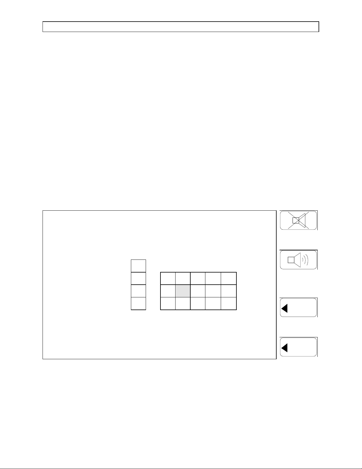
2.1.1.1 Key Panel Test Screen
Pressing the KEY TEST key in the Diagnostics Menu
Screen allows the TSR to check each key on the display
panel. As each key on the display panel is pressed, a
corresponding key is illuminated on the Key Panel Test
Screen as shown in Figure 2-4.
NOTE: The TREND key should be pressed last,
because it also exits the Key Panel Test
Screen.
If the correct keypanel response is not obtained, refer to
Section 3 for the appropriate troubleshooting procedure.
Figure 2-4: KEY PANEL TEST SCREEN
2-6
EXIT
TRACE
TREND
Page 17
RETURN TO THIS MANUAL'S TABLE OF CONTENTS
RETURN TO CD-ROM TABLE OF CONTENTS
NM2B DIAGNOSTICS (continued)
2.1.2 Calibration Menu Screen
Pressing the CALIBRATION key on the Service Menu Screen brings up
the Calibration Menu Screen. This menu allows the TSR to perform
calibration for the Oxygen Analyzer sensor and the Breathing Pressure
Monitor. Figure 2-5 shows a typical Calibration Menu Screen. The fourdigit numbers in the left column show the current values, while the
numbers in the right column show the values stored from the previous
calibration.
For a valid zero calibration of the Oxygen Analyzer sensor, the two
offset readings should be between 125 and 145, and the difference
between Cell A and Cell B should be no greater than 8. Pressing the
O2MED key stores the values, and the message OXYGEN OFFSET
READINGS STORED appears on the screen. Refer to Section 5 of this
manual for the complete calibration procedure.
For a valid calibration of the Breathing Pressure Monitor, the pressure
span reading at 60 cm H
the BAROMED key stores the value, and the message PRESSURE
SPAN READING STORED appears on the screen. Refer to Section 5 of
this manual for the complete calibration procedure.
O should be between 465 and 519. Pressing
2
CALIBRATION MENU O2MED
OFFSET O2 CELL A 0138 0127
OFFSET O2 CELL B 0138 0129
BAROMED
OXYGEN OFFSET READINGS STORED
TRACE
PRESSURE SPAN (60 cm H2O) 0243 0481
Figure 2-5: CALIBRATION MENU SCREEN
Rev. A
2-7
EXIT
TREND
Page 18

RETURN TO THIS MANUAL'S TABLE OF CONTENTS
RETURN TO CD-ROM TABLE OF CONTENTS
Page 19

RETURN TO THIS MANUAL'S TABLE OF CONTENTS
RETURN TO CD-ROM TABLE OF CONTENTS
NM2B TROUBLESHOOTING GUIDE
3.0 TROUBLESHOOTING
This section contains information to assist the Draeger Medical, Inc. qualified
Technical Service Representative (TSR) in locating electrical faults affecting the
NARKOMED 2B monitoring and display devices. Since most troubleshooting efforts
begin with verifying power supply voltages, the following paragraph outlines the
voltage distribution scheme within the machine along with test points for each of the
voltages.
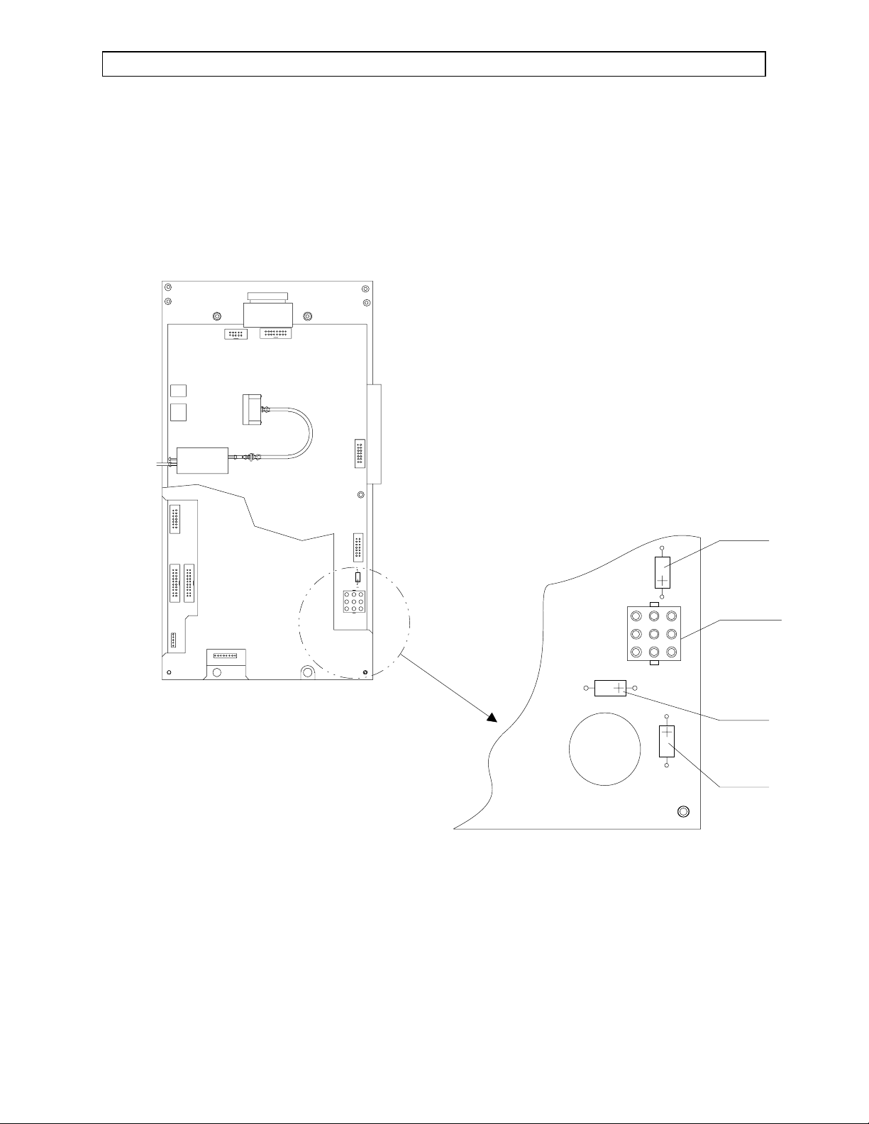
3.1 Power Supply and Voltage Distribution
In the NARKOMED 2B the power supply outputs at J10 are connected to J5
on the processor board for distribution. The CRTs are powered by 12 VDC; the
ventilator controller and the alarm channel are powered by 8 VDC. The
processor is powered by 5 VDC along with the other voltages. Under normal
load conditions these voltages are measured at the (+) end of capacitors C23,
C24 and C31 on the processor board. See Figure 3-1. The voltmeter return
should be connected to the (-) end of one of the capacitors. Table 3-1 lists the
acceptable range for each voltage.
TABLE 3-1: PROCESSOR BOARD VOLTAGES
LOCATION VOLTAGE ACCEPTABLE RANGE
+ End of C23 + 5 VDC 4.85 to 5.15 VDC
+ End of C24 + 8 VDC 7.45 to 8.47 VDC
+ End of C31 +12VDC 11.52 to 12.24 VDC
The power supply voltages can also be measured in an unloaded condition.
CAUTION
: Before disconnecting the output cable from J10 on the power
supply assembly, turn the System Power switch to STANDBY,
and disconnect the data cable from J9 on the power supply
assembly.
The test points are:
+5V: J10-3,-4
+8V: J10-1,-2
+12V: J10-5,-6
Com: J10-7,-8
Rev. H
3-1
Page 20
RETURN TO THIS MANUAL'S TABLE OF CONTENTS
RETURN TO CD-ROM TABLE OF CONTENTS
TROUBLESHOOTING GUIDE (continued) NM2B
TOP VIEW OF
PROCESSOR ASSEMBLY
SV20313
C31
J5
C24
C23
Figure 3-1: PROCESSOR BOARD VOLTAGE TEST POINTS
3-2
Rev. A
Page 21

RETURN TO THIS MANUAL'S TABLE OF CONTENTS
RETURN TO CD-ROM TABLE OF CONTENTS
NM2B TROUBLESHOOTING GUIDE (continued)
3.2 Battery
While the machine is operating from an AC line, the battery voltage at full
charge should be within the range of 12.83 to 14.18 VDC. Battery voltage can
be measured between J7-3(+) and J7-4(-). During battery operation, the low
battery cutoff voltage should be within the range of 9.79 to 10.82 VDC.
3.3 Troubleshooting Guides
Table 3-2 lists common failure modes and symptoms (excluding simultaneous
multiple faults) for the monitoring and display devices in the NARKOMED 2B.
Each failure mode or symptom is keyed to a troubleshooting guide flow chart
on the following pages to assist in locating a problem. These flow charts
assume that the machine is plugged into an AC outlet with the correct voltage,
and the machine is not running on its backup battery.
TABLE 3-2: NARKOMED 2B FAILURE MODE AND SYMPTOM LIST
FAILURE MODE / SYMPTOM CORRECTIVE ACTION
Loss of O2Monitor Guide 1
Loss of Breathing Pressure Monitor Guide 2
Loss of Respiratory Volume Monitor Guide 3
No Audio Alarms Guide 4
Vitalink Failure Guide 5
Incorrect Display Guide 6
No Oxygen Ratio Monitor Alarms Guide 7
No Oxygen Supply Pressure Alarms Guide 8
Display Screens Blank Upon System Power-up Guide 9
No Keypanel Response Guide 10
Rev. A
3-3
Page 22
RETURN TO THIS MANUAL'S TABLE OF CONTENTS
RETURN TO CD-ROM TABLE OF CONTENTS
TROUBLESHOOTING GUIDE (continued) NM2B
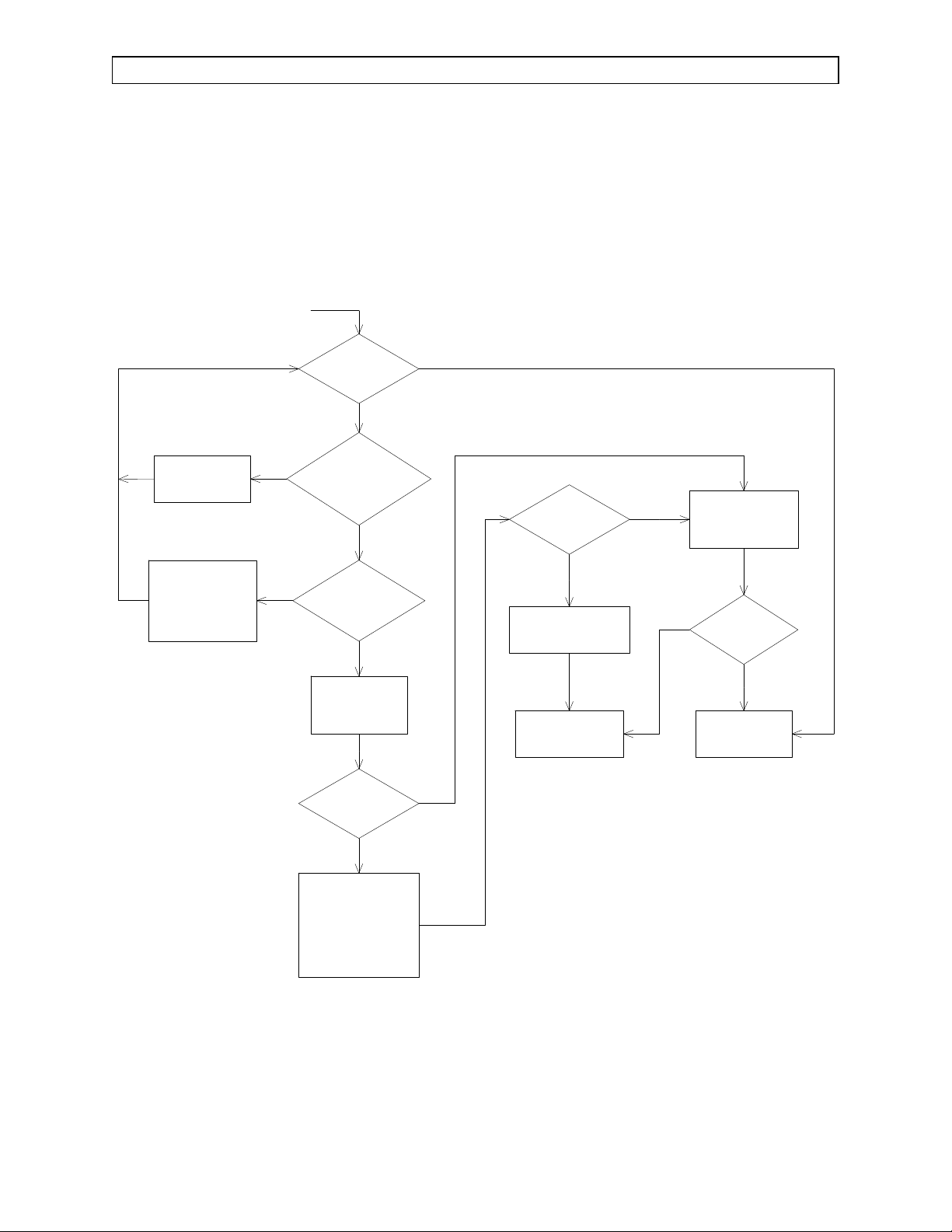
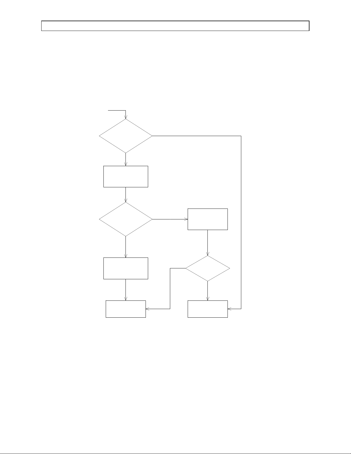
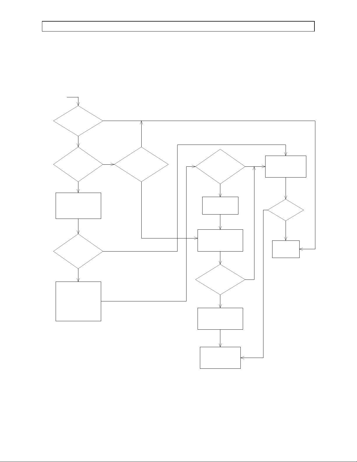
GUIDE 1: Loss of O
CONNECT OXYGEN
SENSOR CABLE TO
INTERFACE PANEL
CONNECT CABLE TO
J10 ON PROCESSOR
BOARD (ALSO
CHECK CONTINUITY OF
INTERNAL CABLE)
Monitor
2
START
Y
CENTRALERT ALARM
N
IS
OXYGEN ANALYZER
FUNCTIONAL?
N
IS
"O2 SENS DISC"
DISPLAYED ON
DISPLAY?
N
IS CABLE
CONNECTED TO
J10 ON PROCESSOR
BOARD?
Y
Y
N
PERFORM A
COMPLETE PMS
ON UNIT
DOES UNIT
PASS PMS?
IS
OXYGEN ANALYZER
FUNCTIONAL?
N
REINSTALL ORIGINAL
PROCESSOR ASSEMBLY
Y
REPLACE
OXYGEN SENSOR
ASOUTLINED IN
PROCEDURE 4.30
IS
OXYGEN ANALYZER
FUNCTIONAL?
N
REINSTALL ORIGINAL
OXYGEN SENSOR
-----------------------REPLACE
PROCESSOR ASSEMBLY
AS OUTLINED IN
PROCEDURE 4.26
Y
CONTACT NAD
SERVICE DEPT.
Y
UNIT IS
FUNCTIONAL
3-4
Rev. A
Page 23
RETURN TO THIS MANUAL'S TABLE OF CONTENTS
RETURN TO CD-ROM TABLE OF CONTENTS
NM2B TROUBLESHOOTING GUIDE (continued)
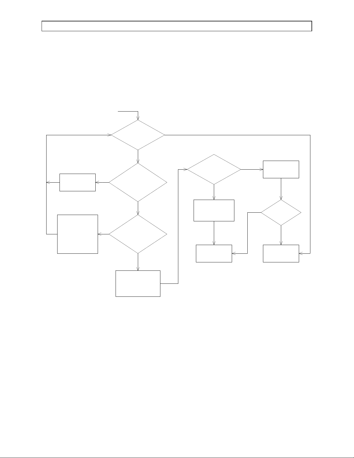
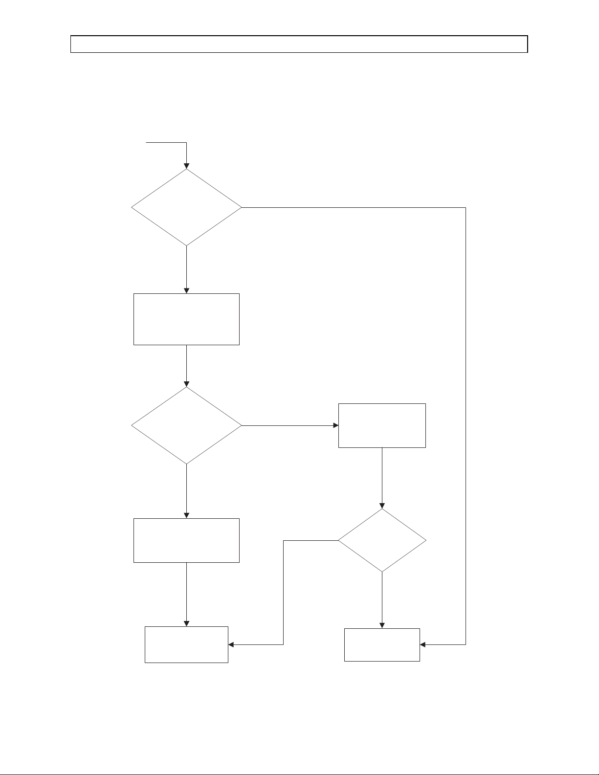
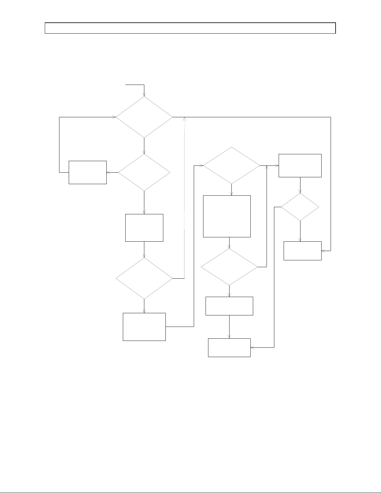
GUIDE 2: Loss of Breathing Pressure Monitor
START
CONNECT
PILOT LINE
AT BOTH ENDS
CONNECT TUBING TO
TRANSDUCER ON
PROCESSOR BOARD
(ALSO CHECK
CONTINUITY OF
INTERNAL TUBING
CONNECTIONS)
PRESSURE MONITOR
FUNCTIONAL?
N
N
CONNECTED TO
INTERFACE PANEL AND TO
PATIENT Y-PIECE OR
PRESSURE TUBING
CONNECTED TO
TRANSDUCER ON
PROCESSOR
PROCESSOR ASSEMBLY
AS OUTLINED IN
PROCEDURE 4.26
IS
BREATHING
N
IS
PILOT LINE
ABSORBER?
Y
IS
BREATHING
BOARD?
Y
REPLACE
Y
IS
BREATHING
PRESSURE MONITOR
FUNCTIONAL?
N
REINSTALL ORIGINAL
PROCESSOR
ASSEMBLY
CONTACT NAD
SERVICE DEPT.
Y
N
PERFORM A
COMPLETE PMS
ON UNIT
DOES
UNIT PASS
PMS?
Y
UNIT IS
FUNCTIONAL
Rev. A
3-5
Page 24

RETURN TO THIS MANUAL'S TABLE OF CONTENTS
RETURN TO CD-ROM TABLE OF CONTENTS
TROUBLESHOOTING GUIDE (continued) NM2B
GUIDE 3: Loss of Respiratory Volume Monitor
START
CONNECT VOLUME
SENSOR CABLE TO
INTERFACE PANEL
CONNECT CABLE TO
J9 ON PROCESSOR
BOARD (ALSO
CHECK CONTINUITY OF
INTERNAL CABLE)
VOLUME MONITOR
Y
CENTRALERT ALARM
N
J9 ON PROCESSOR
VOLUME MONITOR
IS
FUNCTIONAL?
N
IS
"VOL SENS DISC"
DISPLAYED ON
DISPLAY?
N
IS CABLE
CONNECTED TO
BOARD?
Y
REPLACE
VOLUME SENSOR
ASOUTLINED IN
PROCEDURE 4.29
IS
FUNCTIONAL?
Y
N
PERFORM A
COMPLETE PMS
ON UNIT
DOES UNIT
PASS PMS?
Y
UNIT IS
FUNCTIONAL
IS
VOLUME MONITOR
FUNCTIONAL?
N
REINSTALL ORIGINAL
PROCESSOR ASSEMBLY
CONTACT NAD
SERVICE DEPT.
Y
Y
N
REINSTALL ORIGINAL
VOLUME SENSOR
-----------------------REPLACE
PROCESSOR ASSEMBLY
AS OUTLINED IN
PROCEDURE 4.26
3-6
Rev. A
Page 25
RETURN TO THIS MANUAL'S TABLE OF CONTENTS
RETURN TO CD-ROM TABLE OF CONTENTS
NM2B TROUBLESHOOTING GUIDE (continued)
GUIDE 4: No Audio Alarms
START
ARE
WARNINGS AND
CAUTIONS AUDIBLY
ANNUNCIATED?
N
REPLACE
PROCESSOR ASSEMBLY
AS OUTLINED IN
PROCEDURE 4.26
ARE
WARNINGS AND
CAUTIONS AUDIBLY
ANNUNCIATED?
N
REINSTALL ORIGINAL
PROCESSOR ASSEMBLY
Y
Y
N
PERFORM A
COMPLETE PMS
ON UNIT
DOES
UNIT PASS
PMS?
Y
Rev. A
CONTACT NAD
SERVICE DEPT.
3-7
UNIT IS
FUNCTIONAL
Page 26
RETURN TO THIS MANUAL'S TABLE OF CONTENTS
RETURN TO CD-ROM TABLE OF CONTENTS
TROUBLESHOOTING GUIDE (continued) NM2B
GUIDE 5: Vitalink Failure
START
CONNECT
PERIPHERAL CABLE
TO SERIAL
HOST FAIL TO
COMMUNICATE WITH
N
CABLE CONNECTED
TO SERIAL INTERFACE
CHECK PERIPHERAL
& HOST SERIAL
CONFIGURATION
HOST FAIL TO
COMMUNICATE WITH
DOES
PERIPHERAL
DEVICE?
Y
IS
PERIPHERAL
PORT?
Y
PORT
SETTINGS
DOES
PERIPHERAL
DEVICE?
N
N
DOES
HOST FAIL TO
COMMUNICATE WITH
PERIPHERAL
DEVICE?
N
REINSTALL ORIGINAL
PROCESSOR ASSEMBLY
Y
CONTACT NAD
SERVICE DEPT.
Y
N
PERFORM A
COMPLETE PMS
ON UNIT
DOES UNIT
PASS PMS?
Y
UNIT IS
FUNCTIONAL
REPLACE
PROCESSOR ASSEMBLY
AS OUTLINED IN
PROCEDURE 4.26
3-8
Rev. A
Page 27
RETURN TO THIS MANUAL'S TABLE OF CONTENTS
RETURN TO CD-ROM TABLE OF CONTENTS
NM2B TROUBLESHOOTING GUIDE (continued)
GUIDE 6: Incorrect Display
START
IS WRONG
MONITOR SCREEN
DISPLAYED?
Y
REPLACE
PROCESSOR ASSEMBLY
AS OUTLINED IN
PROCEDURE 4.26
IS WRONG
MONITOR SCREEN
DISPLAYED?
Y
N
N
PERFORM A
COMPLETE PMS
ON UNIT
Rev. A
REINSTALL ORIGINAL
PROCESSOR ASSEMBLY
CONTACT NAD
SERVICE DEPT.
3-9
N
DOES
UNIT PASS
PMS?
Y
UNIT IS
FUNCTIONAL
Page 28
RETURN TO THIS MANUAL'S TABLE OF CONTENTS
RETURN TO CD-ROM TABLE OF CONTENTS
TROUBLESHOOTING GUIDE (continued) NM2B
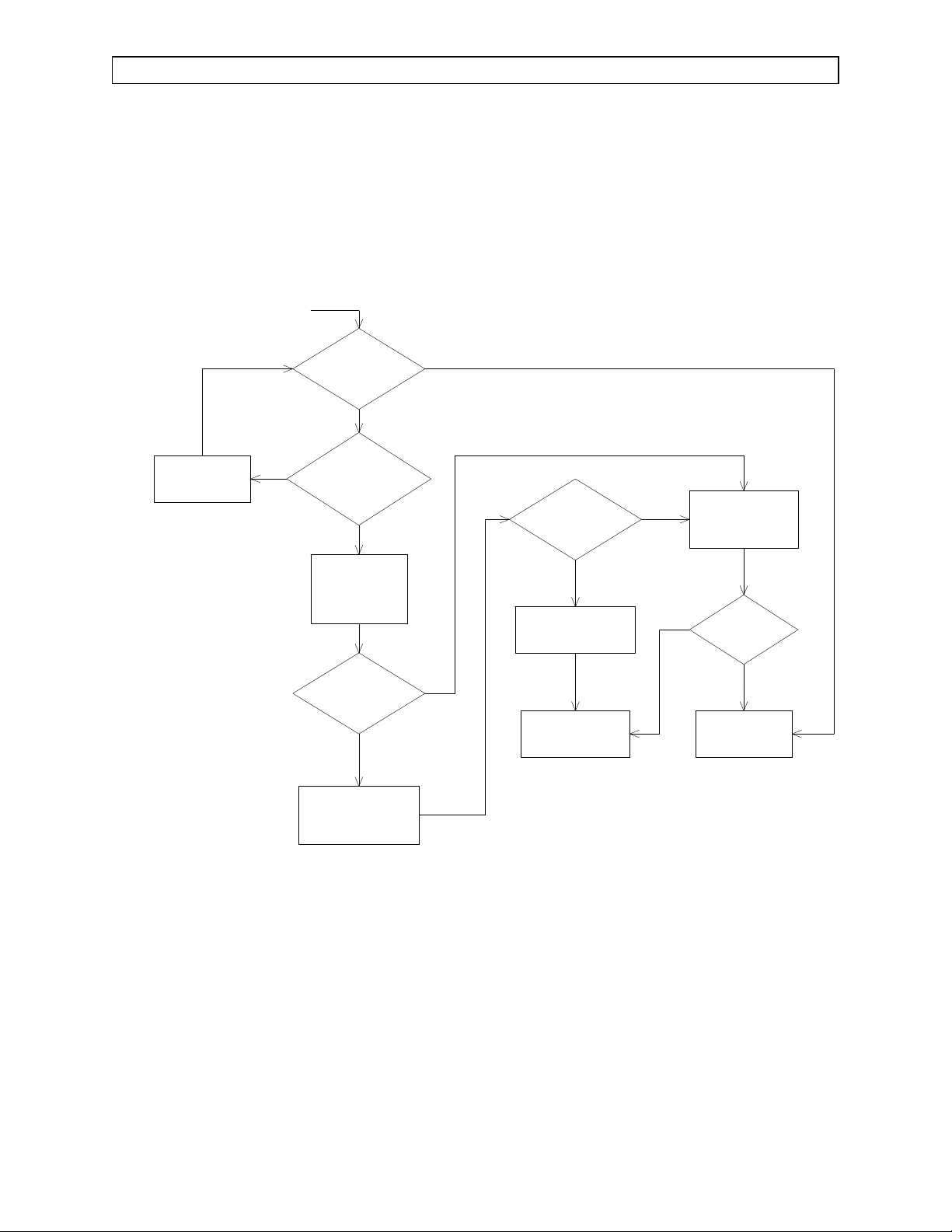
GUIDE 7: No Oxygen Ratio Monitor Alarms
START
ARE O2 / N2O
RATIO ALARMS
FUNCTIONAL?
N
IS O2 / N2O
FLOW RATIO
LED INDICATOR
FUNCTIONAL?
N
CHECK ORMC
ADJUSTMENTS
AS OUTLINED IN
PROCEDURE 5.4
IS O2 / N2O
FLOW RATIO
LED INDICATOR
FUNCTIONAL?
N
REPLACE ALARM
CHANNEL ASSEMBLY
AS OUTLINED IN
PROCEDURE 4.21
Y
Y
IS
Y
Y
"O2 / N20 LOW"
DISPLAYED ON
CENTRALERT ALARM
PANEL?
N
IS O2 / N2O
FLOW RATIO
LED INDICATOR
FUNCTIONAL?
N
REINSTALL ORIGINAL
ORMC
REPLACE
PROCESSOR ASSEMBLY
AS OUTLINED IN
PROCEDURE 4.26
ARE O2 / N2O
RATIO ALARMS
FUNCTIONAL?
N
Y
Y
COMPLETE PMS
N
FUNCTIONAL
PERFORM A
ON UNIT
DOES
UNIT PASS
PMS?
Y
UNIT IS
IS O2 / N2O
FLOW RATIO
LED INDICATOR
FUNCTIONAL?
N
REINSTALL ORIGINAL
ALARM CHANNEL
-------------------REPLACE ORMC
AS OUTLINED IN
PROCEDURE 4.10
REINSTALL ORIGINAL
PROCESSOR
ASSEMBLY
Y
CONTACT NAD
SERVICE DEPT.
3-10
Rev. A
Page 29
RETURN TO THIS MANUAL'S TABLE OF CONTENTS
RETURN TO CD-ROM TABLE OF CONTENTS
NM2B TROUBLESHOOTING GUIDE (continued)
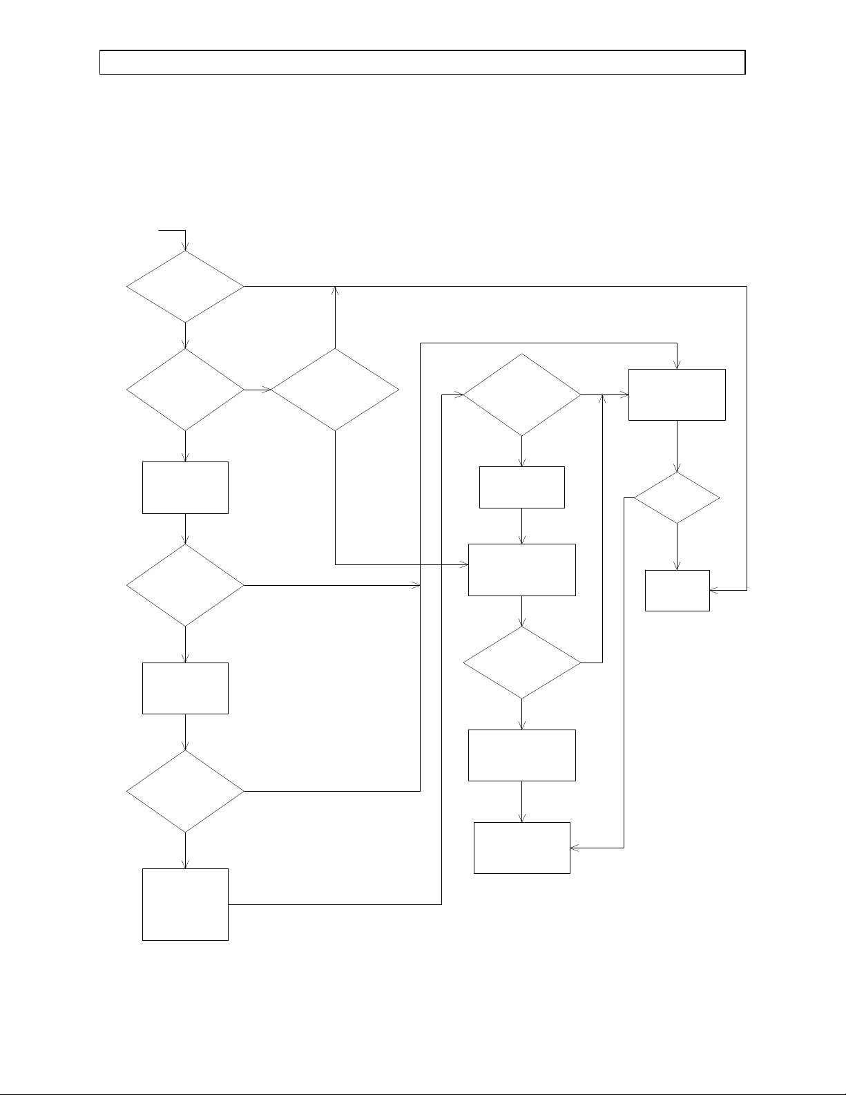
GUIDE 8: No Oxygen Supply Pressure Alarms
START
ARE
OXYGEN SUPPLY
PRESSURE ALARMS
FUNCTIONAL?
N
IS O2
SUPPLY PRESSURE
LED INDICATOR
FUNCTIONAL?
N
REPLACE OXYGEN
SUPPLY PRESSURE
ALARM SWITCH
AS OUTLINED IN
PROCEDURE 4.8 OR 4.22
IS O2
SUPPLY PRESSURE
LED INDICATOR
FUNCTIONAL?
N
REINSTALL ORIGINAL
OXYGEN SUPPLY
ALARM SWITCH
--------------------
REPLACE
ALARM CHANNEL
AS OUTLINED IN
PROCEDURE 4.21 OR 4.22
Y
Y
IS
Y
Y
"LOW O2 SUPPLY"
DISPLAYED ON
CENTRALERT ALARM
PANEL?
N
IS O2
SUPPLY PRESSURE
LED INDICATOR
FUNCTIONAL?
N
REINSTALL ORIGINAL
ALARM CHANNEL
REPLACE
PROCESSOR ASSEMBLY
AS OUTLINED IN
PROCEDURE 4.26
ARE
OXYGEN SUPPLY
PRESSURE ALARMS
FUNCTIONAL?
N
REINSTALL ORIGINAL
PROCESSOR
ASSEMBLY
Y
Y
COMPLETE PMS
N
FUNCTIONAL
PERFORM A
ON UNIT
DOES
UNIT PASS
PMS?
Y
UNIT IS
Rev. A
3-11
CONTACT NAD
SERVICE DEPT.
Page 30
RETURN TO THIS MANUAL'S TABLE OF CONTENTS
RETURN TO CD-ROM TABLE OF CONTENTS
TROUBLESHOOTING GUIDE (continued) NM2B
GUIDE 9: Display Screens Blank Upon System Power-Up
START
CONNECT
CABLES
TO J3 & J4 ON
PROCESSOR
ARE
DISPLAY SCREENS
BLANK UPON SYSTEM
POWER-UP?
ARE
N
CABLES
CONNECTED TO J3 & J4
ON PROCESSOR
BOARD?
CHECK POWER
SUPPLY
VOLTAGES
AS OUTLINED IN
SECTION 3.1
ARE
DISPLAY SCREENS
BLANK UPON SYSTEM
POWER-UP?
N
Y
ARE
DISPLAY SCREENS
BLANK UPON SYSTEM
POWER-UP?
Y
Y
N
REINSTALL ORIGINAL
CRT ASSEMBLY
----------------------REPLACE
PROCESSOR
ASSEMBLY
AS OUTLINED IN
PROCEDURE 4.26
ARE
DISPLAY SCREENS
BLANK UPON SYSTEM
POWER-UP?
Y
N
N
PERFORM A
COMPLETE PMS
ON UNIT
N
DOES UNIT
PASS PMS?
FUNCTIONAL
Y
UNIT IS
Y
REPLACE
CRT ASSEMBLY
AS OUTLINED IN
PROCEDURE 4.27
3-12
REINSTALL ORIGINAL
PROCESSOR
ASSEMBLY
CONTACT NAD
SERVICE DEPT.
Rev. D
Page 31

RETURN TO THIS MANUAL'S TABLE OF CONTENTS
RETURN TO CD-ROM TABLE OF CONTENTS
NM2B TROUBLESHOOTING GUIDE (continued)
GUIDE 10: No Keypanel Response
START
CONNECT CABLES
TO J1 & J2 ON
PROCESSOR BOARD
ARE
DISPLAY PANEL
KEYS WORKING
PROPERLY?
N
ARE
CABLES
CONNECTED TO J1 & J2
ON PROCESSOR
BOARD?
REPLACE KEYPAD
AS OUTLINED IN
PROCEDURE 4.28
ARE
DISPLAY PANEL
KEYS WORKING
PROPERLY?
Y
N
ARE
DISPLAY PANEL
KEYS WORKING
PROPERLY?
N
Y
REINSTALL ORIGINAL
PROCESSOR ASSEMBLY
CONTACT NAD
SERVICE DEPT.
Y
Y
N
PERFORM A
COMPLETE PMS
ON UNIT
DOES UNIT
PASS PMS?
Y
UNIT IS
FUNCTIONAL
Rev. A
N
REINSTALL ORIGINAL
KEYPAD
-----------------------REPLACE
PROCESSOR ASSEMBLY
AS OUTLINED IN
PROCEDURE 4.26
3-13
Page 32

RETURN TO THIS MANUAL'S TABLE OF CONTENTS
RETURN TO CD-ROM TABLE OF CONTENTS
Page 33

RETURN TO THIS MANUAL'S TABLE OF CONTENTS
RETURN TO CD-ROM TABLE OF CONTENTS
NM2B REPLACEMENT PROCEDURES
4.0 REPLACEMENT PROCEDURES
This section outlines removal and replacement procedures for the field-replaceable
assemblies of the NARKOMED 2B Anesthesia System.
These procedures are to be performed only by a Draeger Medical, Inc. qualified
Technical Service Representative (TSR).
The following are the only procedures authorized by Draeger Medical, Inc. to be
performed in the field. All other service procedures shall be referred to NAD’s
Technical Service Department.
NOTE: The PMS PROCEDURE detailed in Section 6 must be
performed after any replacement, removal, calibration or
adjustment procedure.
Rev. H
4-1
Page 34

RETURN TO THIS MANUAL'S TABLE OF CONTENTS
RETURN TO CD-ROM TABLE OF CONTENTS
REPLACEMENT PROCEDURES (continued) NM2B
4.1 Cylinder Yoke Assemblies
Each cylinder yoke contains a replaceable filter and check valve assembly.
Replacement of this assembly requires that the yoke be removed from the
anesthesia machine. Figure 4-1 shows a typical cylinder yoke mounting
arrangement. Access to the yoke mounting screws and gas line connection
requires that the table top be removed from the machine.
4.1.1 Disconnect all pipeline hoses and set the System Power switch to ON.
4.1.2 Close all cylinder valves except the O
valve.
2
4.1.3 Set the oxygen flow to 5 liters per min.
4.1.4 Open the other gas flow control valves to drain pressure from the
system.
4.1.5 Close the O
the O
Flush valve to drain oxygen pressure from the system.
2
cylinder valve, and close the flow control valves. Press
2
4.1.6 Set the System Power switch to STANDBY.
4.1.7 Remove the cylinder where the yoke is to be replaced.
WARNING: Store the cylinder in a safe place and lay it on its side.
4.1.8 Remove the screws holding the table top to the machine and lift out
the table top.
4.1.9 Pull the writing or keyboard tray out to its fully extended position.
4.1.10 Disconnect the gas line fitting at the yoke and remove the two yoke
mounting screws.
4.1.11 Remove the filter and check valve assembly from the yoke and install
a replacement assembly.
NOTE: If the entire yoke assembly is being replaced, ensure that the
replacementyoke has the correct label and pinindexing arrangement.
NOTE: If the yoke spacer is removed from the frame rail of the machine, be
sure to re-install it in its original position.
4-2
Rev. A
Page 35

YOKE
ASSEMBLY
(TYPICAL)
FILTER AND
CHECK VALVE
ASSEMBLY
GAS LINE
YOKE
SPACER
SV40601
RETURN TO THIS MANUAL'S TABLE OF CONTENTS
RETURN TO CD-ROM TABLE OF CONTENTS
NM2B REPLACEMENT PROCEDURES (continued)
Figure 4-1: CYLINDER YOKE ASSEMBLY
Rev. J
4-3
Page 36

RETURN TO THIS MANUAL'S TABLE OF CONTENTS
RETURN TO CD-ROM TABLE OF CONTENTS
REPLACEMENT PROCEDURES (continued) NM2B
4.1.12 Position the yoke on the spacer, and install the two mounting screws
and lockwashers. Tighten the screws securely. Connect the gas line
fitting to the yoke.
4.1.13 If a new cylinder is being installed, remove the old sealing washer
from the gas inlet of the yoke and install a new washer.
4.1.14 Install the correct cylinder in the yoke, making sure that the index
pins are properly engaged before tightening the handle bolt. The
cylinder should hang vertically after the handle is tight.
4.1.15 Perform the following leak test on the yoke assembly:
4.1.15.1 Open the cylinder valve and check for a pressure
indication on the corresponding gauge at the gas
instrumentation panel.
NOTE: The cylinder used for this test must
contain the following minimum pressure:
O
N
: 1000 PSI
2
O : 700 PSI
2
HE : 1000 PSI
CO
: 800 PSI
2
AIR : 1000 PSI
N
O
: 1000 PSI
2
-He : 1000 PSI
2
4.1.15.2 Closethe cylinder valve and remove the cylinder from the
yoke.
4.1.15.3 For any gas, the pressure should not drop more than 50
PSI in two minutes.
4.1.16 Re-install the cylinder in the yoke.
4.1.17 Replace the table top and its retaining screws.
4.1.18 Replace the pipeline hoses.
4.1.19 Perform the PMS Procedure given in Section 6.
4-4
Rev. A
Page 37

RETURN TO THIS MANUAL'S TABLE OF CONTENTS
RETURN TO CD-ROM TABLE OF CONTENTS
NM2B REPLACEMENT PROCEDURES (continued)
4.2 Cylinder Pressure Regulators
Access to the cylinder pressure regulators requires that the table top be
removed from the anesthesia machine. Figure 4-2 shows the mounting
arrangement of the regulators and typical connections.
4.2.1 Disconnect all pipeline hoses and set the System Power switch to ON.
4.2.2 Close all cylinder valves except the O
valve.
2
4.2.3 Set the oxygen flow to 5 liters per min.
4.2.4 Open the other gas flow control valves to drain pressure from the
system.
4.2.5 Close the O
the O
Flush valve to drain oxygen pressure from the system.
2
cylinder valve, and close the flow control valves. Press
2
4.2.6 Set the System Power switch to STANDBY.
4.2.7 Remove the cylinder corresponding to the regulator to be replaced.
4.2.8 Remove the screws holding the table top to the machine and lift out
the table top.
4.2.9 Remove the top drawer from the cabinet and pull the writing or
keyboard tray out to its fully extended position.
4.2.10 Disconnect the three compression fittings at the regulator.
4.2.11 Loosen the two setscrews holding the regulator to its mounting
bracket and remove the regulator.
Rev. A
4.2.12 Record the serial number of the regulator that was removed, and
record the serial number of the replacement regulator.
NOTE: If fittings must be installed in the replacement regulator, use Loctite
#271 (red). Refer to the parts list in Section 8.
NOTE: For Canadian machines, verify that the correct relief valve is
installed in the regulator. Refer to the parts list in Section 8 for CSA
items.
4.2.13 Position the replacement regulator in its mounting bracket, and
connect the three compression fittings. Do not tighten the fittings yet.
4-5
Page 38

RETURN TO THIS MANUAL'S TABLE OF CONTENTS
RETURN TO CD-ROM TABLE OF CONTENTS
REPLACEMENT PROCEDURES (continued) NM2B
TOP VIEW OF NARKOMED 4
WITH TABLE TOP REMOVED
O CYLINDER
2
PRESSURE
REGULATOR
SET
SCREWS
N O CYLINDER
2
PRESSURE
REGULATOR
AIR OR OPTIONAL
3RD GAS CYLINDER
PRESSURE REGULATOR
TEST GAUGE
CONNECTION
(TYPICAL)
CPR
Figure 4-2: CYLINDER PRESSURE REGULATORS
4-6
SIDE VIEW
ADJUSTMENT
SCREW
ACORN NUT
Rev. J
Page 39

RETURN TO THIS MANUAL'S TABLE OF CONTENTS
RETURN TO CD-ROM TABLE OF CONTENTS
NM2B REPLACEMENT PROCEDURES (continued)
4.2.14 Tighten the regulator mounting setscrews to a torque of 50 to 55 in.
lbs.
4.2.15 Tighten the compression fittings.
4.2.16 Locate the TEE fitting in the ¼ in. diameter regulator output line,
and remove the plug from the TEE fitting.
4.2.17 Set the regulator output pressure in accordance with the Cylinder
Pressure Regulator Adjustment given in Section 5.
4.2.18 Perform the following leak test on the high pressure side of the
regulator:
4.2.18.1 Open the cylinder valve and check for a pressure
indication on the corresponding gauge at the gas
instrumentation panel.
NOTE: The cylinder used for this test must
contain the following minimum pressure:
O
N
: 1000 Psi
2
O : 700 Psi
2
HE : 1000 Psi
CO
: 800 Psi
2
AIR : 1000 Psi
2
: 1000 Psi
N
4.2.18.2 Closethe cylinder valve and remove the cylinder from the
yoke.
4.2.18.3 For any gas, the pressure should not drop more than 50
Psi in two minutes.
4.2.19 Re-install the cylinder in the yoke.
4.2.20 Replace the table top and its retaining screws.
4.2.21 Replace the top drawer in the cabinet.
4.2.22 Connect the pipeline hoses.
Rev. A
4.2.23 Perform the PMS Procedure given in Section 6.
4-7
Page 40

RETURN TO THIS MANUAL'S TABLE OF CONTENTS
RETURN TO CD-ROM TABLE OF CONTENTS
REPLACEMENT PROCEDURES (continued) NM2B
4.3 Cylinder Cutoff Valves (Canada)
Access to the cylinder cutoff valves requires removal of the table top from the
anesthesia machine. Figure 4-3 shows the locations of the O
andN
Ocutoff valve assemblies. The instructions apply to all three assemblies.
2
, Air or 3rd gas,
2
On earlier machines the tubing arrangement may be slightly different from
that illustrated.
NOTE: Replacement of the O
Cutoff Valve Assembly shall be performed every
2
24 months. Documentation shall be created by the service person and a copy
distributed to the owner institution. Testing of the O
Cutoff Valve shall be
2
performed at each PMS. (Perform the flow test given at the end of the
following procedure)
4.3.1 Disconnect all pipeline hoses and set the System Power switch to ON.
4.3.2 Close all cylinder valves except the O
valve.
2
4.3.3 Set the oxygen flow to 5 liters per min.
4.3.4 Open the other gas flow control valves to drain pressure from the
system.
4.3.5 Close the O
the O
Flush valve to drain oxygen pressure from the system.
2
cylinder valve, and close the flow control valves. Press
2
4.3.6 Set the System Power switch to STANDBY.
4.3.7 Remove the screws holding the table top to the machine and lift out
the table top.
4.3.8 Remove the top drawer from the cabinet and pull the writing or
keyboard tray out to its fully extended position.
4.3.9 Disconnect the compression fittings indicated at points marked C on
the illustration.
4.3.10 Cut the tie-wrap clamp and disconnect the flexible tubing from the
cutoff valve assembly at the point marked A on the illustration.
NOTE: On later machines with assemblies that have brass fittings instead
of nylon, the flex tubing is attached with a press-on hose clamp
instead of a tie strap.
4.3.11 Remove the cylinder cutoff assembly.
4.3.12 Connect the flexible tubing to the replacement cutoff valve assembly
and secure it with a new tie-wrap clamp.
4-8
Rev. D
Page 41

SV50526
O2 CYLINDER
CUTOFF VALVE
ASSEMBLY
AIR OR 3RD GAS
CYLINDER
CUTOFF VALVE
ASSEMBLY
N2O CYLINDER
CUTOFF VALVE
ASSEMBLY
A
C
C
C
A
C
C
C
C
A
RETURN TO THIS MANUAL'S TABLE OF CONTENTS
RETURN TO CD-ROM TABLE OF CONTENTS
NM2B REPLACEMENT PROCEDURES (continued)
Figure 4-3: CYLINDER CUTOFF VALVES (CANADA)
Rev. J
4-9
Page 42

RETURN TO THIS MANUAL'S TABLE OF CONTENTS
RETURN TO CD-ROM TABLE OF CONTENTS
REPLACEMENT PROCEDURES (continued) NM2B
4.3.13 Connect and tighten the compression fittings at points marked C on
the illustration.
4.3.14 Perform the following test: --Remove the plug from the test gauge
connection at the Tee fitting in the regulator outlet piping, and install
a test gauge.
NOTE: The cylinders used for this test must contain the following minimum
pressure: O
O
: 1000 PSI AIR : 1000 PSI
2
+He : 1000 PSI N2O : 745 PSI
2
--Set the System Power switch to ON.
--For the O
cutoff valve: open the O2cylinder valve and set the oxygen flow to
2
4 liters per min.
--For the N
O cutoff valve: open the O2cylinder valve and the N2O cylinder
2
valve. Set each flow to 4 liters per min.
--Verify that regulator outlet pressure is between 43 and 49 PSI.
--Connect the pipeline hoses and pressurize to 50 PSI.
--Turn off the pipeline supply and observe the pipeline pressure gauge.
--The cutoff valve shall open when the pipeline pressure drops through the
range of 45 to 40 PSI.
--Close the cylinder valve(s), and close the flow control valve(s).
--Disconnect test pressure gauge and reinstall the plug in the regulator outlet
piping.
4.3.15 Replace the table top and its retaining screws.
4.3.16 Replace the top drawer in the cabinet.
4.3.17 Connect the pipeline hoses.
4.3.18 Perform the PMS Procedure given in Section 6.
O
Flow Test:
2
--Disconnect all pipeline supplies.
--Install a full O2cylinder on the machine, and open the cylinder valve.
--Turn the System Power switch to ON.
--Set the Inspiratory Flow control to maximum high, and turn the ventilator switch to ON.
--Set the oxygen flow to 10 l/min.
--Verify that the oxygen flow does not drop below 8 l/min. while the ventilator is running.
--Press and hold the O2FLUSH button while observing the O2flowmeter, and verify that the
oxygen flow does not drop below 8 l/min.
--If the oxygen flow in either of the above two steps drops below 8 l/min., replace the O2cutoff
valve assembly.
4-10
Rev. D
Page 43

RETURN TO THIS MANUAL'S TABLE OF CONTENTS
RETURN TO CD-ROM TABLE OF CONTENTS
NM2B REPLACEMENT PROCEDURES (continued)
4.4 Cylinder and Pipeline Pressure Gauges
Replacement of the cylinder and pipeline pressure gauges requires that the
plexiglass front cover be removed from the gas instrumentation panel, and also
the rear cover for access to the gauge connections. Figure 4-4 shows
disassembly and mounting details.
4.4.1 Disconnect all pipeline hoses and set the System Power switch to ON.
4.4.2 Close all cylinder valves except the O
valve.
2
4.4.3 Set the oxygen flow to 5 liters per min.
4.4.4 Open the other gas flow control valves to drain pressure from the
system.
4.4.5 Close the O
the O
Flush valve to drain oxygen pressure from the system.
2
cylinder valve, and close the flow control valves. Press
2
4.4.6 Set the System Power switch to STANDBY.
4.4.7 Remove the screws holding the rear cover, and remove the cover.
4.4.8 Remove the screws holding the table top to the machine and lift out
the table top.
4.4.9A Early models: Remove the two screws (from the back) holding the
front plate at the top of the plexiglass cover. Hold the front plate as
the screws are removed from the back.
4.4.9B Later models (without the O
O ratio alarm lamp): Remove the six
2/N2
screws holding the flowmeter shield and vapor box cover panel, and
remove the panel.
Rev. A
4.4.10 Remove the O
flow control knob. The knob has two setscrews.
2
NOTE: If the knob must be rotated to allow access to a setscrew,
carefully note its position so that it can be re-assembled
in the same position with the "Off Stop" properly set.
4.4.11 Remove the two screws holding the knob guard in place, and remove
the knob guard. (For earlier machines with the bar-type knob guard,
the screws holding the guard assembly are accessible through the
back of the flowmeter housing.)
4.4.12 Remove the screws holding the plexiglass cover over the flow tubes
and gauges, and carefully remove the cover.
4-11
Page 44

RETURN TO THIS MANUAL'S TABLE OF CONTENTS
RETURN TO CD-ROM TABLE OF CONTENTS
REPLACEMENT PROCEDURES (continued) NM2B
REAR VIEW OF
FLOWMETER HOUSING
WITH REAR COVER REMOVED
FRONT COVER
RETAINER SCREWS
FLEXIBLE
TUBING
CONNECTION
(PIPELINE
PRESSURE
GAUGES)
COMPRESSION FITTING
(CYLINDER PRESSURE GAUGES)
GAUGE
MOUNTING
NUTS (TYPICAL)
SV40644
Figure 4-4: CYLINDER AND PIPELINE PRESSURE GAUGES
4-12
Rev. J
Page 45

RETURN TO THIS MANUAL'S TABLE OF CONTENTS
RETURN TO CD-ROM TABLE OF CONTENTS
NM2B REPLACEMENT PROCEDURES (continued)
NOTE: Intermediateassemblies may need to be removed to allow
access to the gauge connections and mounting hardware.
Be sure to keep a record of the disassembly sequence so
that all tubing can be correctly re-assembled.
4.4.13A For the cylinder pressure gauges:
Disconnect the compression fitting at the back of the gauge.
Remove the gauge mounting nuts, and remove the gauge from
the front of the panel.
Install the replacement gauge in the panel using the flat
washers, lock washers and mounting nuts that were previously
removed.
Connect the gas line to the gauge and tighten the compression
fitting.
4.3.13B For the pipeline pressure gauges:
Locate the flexible tubing connecting the gauge to the pipeline
inlet assembly, cut the tie-wrap tubing clamp at the pipeline
inlet and disconnect the tubing.
NOTE: Onlater machines that have brass fittings instead
of nylon, the flex tubing is attached with a presson hose clamp instead of a tie strap.
Remove the gauge mounting nuts, and remove the gauge from
the front of the panel.
Cut the tie-wrap tubing clamp and disconnect the flexible tubing
from the gauge.
Connect a new 7-inch length of tubing (8-inch for the air pipeline
pressure gauge) to the replacement gauge and secure it with a
new tie-wrap clamp.
Place the gauge in the panel and secure it with the flat washers,
lock washers and mounting nuts that were previously removed.
Rev. C
Connect the other end of the flexible tubing to the pipeline inlet
assembly and secure it with a tie-wrap clamp.
4.4.14 If a cylinder pressure gauge was replaced, perform the following leak
test:
4-13
Page 46

RETURN TO THIS MANUAL'S TABLE OF CONTENTS
RETURN TO CD-ROM TABLE OF CONTENTS
REPLACEMENT PROCEDURES (continued) NM2B
4.4.14.1 Open the cylinder valve and check for a pressure
indication on the corresponding gauge at the gas
instrumentation panel.
NOTE: The cylinder used for this test must
contain the following minimum pressure:
O
N
: 1000 PSI
2
O : 700 PSI
2
HE : 1000 PSI
CO
: 800 PSI
2
AIR : 1000 PSI
N
O
: 1000 PSI
2
-He : 1000 PSI
2
4.4.14.2 Closethe cylinder valve and remove the cylinder from the
yoke.
4.4.14.3 For any gas, the pressure should not drop more than 50
PSI in two minutes.
4.4.15 Reinstall the cylinder in the yoke.
4.4.16 Place the plexiglass cover over the gauges and flow tubes, and
reinstall the cover screws. Do not over-tighten these screws as the
plexiglass may crack.
4.4.17 Place the knob guard over the flow control valves and install its two
retaining screws. (Reinstall the bar-type knob guard on earlier
machines.)
4.4.18 Reinstall the O
knob is installed properly, the O
flow control knob and tighten its setscrews. If the
2
label will be straight when the knob
2
is against its clockwise stop.
4.4.19 Replace the front plate at the top of the plexiglass cover and secure
it with the hardware that was previously removed.
4.4.20 Replace the rear cover and its retaining screws.
4.4.21 Replace the table top and its retaining screws.
4.4.22 Connect the pipeline hoses.
4.4.23 Perform the PMS Procedure given in Section 6.
4-14
Rev. A
Page 47

RETURN TO THIS MANUAL'S TABLE OF CONTENTS
RETURN TO CD-ROM TABLE OF CONTENTS
NM2B REPLACEMENT PROCEDURES (continued)
4.5 Flowmeters
The flowmeter tubes are held by compression in gaskets at the top and bottom
of each tube. Each upper gasket is seated in an adjustable retainer that allows
removal of the tube as shown in Figure 4-5. Access to the flow tubes and their
retainers requires removal of the plexiglass cover on the gas instrumentation
panel.
4.5.1 Disconnect all pipeline hoses and set the System Power switch to ON.
4.5.2 Close all cylinder valves except the O
valve.
2
4.5.3 Set the oxygen flow to 5 liters per min.
4.5.4 Open the other gas flow control valves to drain pressure from the
system.
4.5.5 Close the O
the O
Flush valve to drain oxygen pressure from the system.
2
cylinder valve, and close the flow control valves. Press
2
4.5.6 Set the System Power switch to STANDBY.
4.5.7 Remove the screws holding the table top to the machine and lift out
the table top.
4.5.8 Early models: Remove the flowmeter housing rear cover.
4.5.9A Early models: Remove the two screws (from the back) holding the
front plate at the top of the plexiglass cover. Hold the front plate as
the screws are removed from the back.
4.4.9B Later models (without the O
O ratio alarm lamp): Remove the six
2/N2
screws holding the flowmeter shield and vapor box cover panel, and
remove the panel.
Rev. A
4.5.10 Remove the O
flow control knob. The knob has two setscrews.
2
NOTE: If the knob must be rotated to allow access to a setscrew,
carefully note its position so that it can be re-assembled
in the same position with the "Off Stop" properly set.
4.5.11 Remove the two screws holding the knob guard in place, and remove
the knob guard. (For earlier machines with the bar-type knob guard,
the screws holding the guard assembly are accessible through the
back of the flowmeter housing.)
4.5.12 Remove the screws holding the plexiglass cover over the flow tubes
and gauges, and carefully remove the cover.
4-15
Page 48

FLOW TUBE
RETAINE R SC REW
UPPER FLOW
TUBE RETAINER
FLOW TUBE
LIGHTING CHANNEL
FLOW
RESTRICTOR
SV40605
GASKET
GUIDE RING
RETURN TO THIS MANUAL'S TABLE OF CONTENTS
RETURN TO CD-ROM TABLE OF CONTENTS
REPLACEMENT PROCEDURES (continued) NM2B
Figure 4-5: FLOWMETERS
4-16
Rev. J
Page 49

RETURN TO THIS MANUAL'S TABLE OF CONTENTS
RETURN TO CD-ROM TABLE OF CONTENTS
NM2B REPLACEMENT PROCEDURES (continued)
4.5.13 Loosen the screw directly above the flowmeter tube to be replaced.
Turning the screw counter clockwise will raise the upper flow tube
retainer. Raise the retainer far enough to be able to pull the top of
the tube outward, and remove the tube.
NOTE: If the bottom of the tube is seated in a flow restrictor, be
sure that the arrangement of the restrictor and its
gaskets is not disturbed.
4.5.14 Make sure that the replacement flow tube bears the correct markings
and has a ball.
4.5.15 Place the bottom of the flowmeter tube into the guide ring of the
lower gasket seal, and position the top of the flow tube into the center
guide ring of the top gasket seal. It will be easier to hold the tube if
the adjacent lighting channel is pulled forward and temporarily
removed.
CAUTION: The flowmeter tube must be properly centered over the
guide rings or damage to the flowmeter tube may occur.
4.5.16 Ensure that the markings on the flow tube are facing forward, and
turn the upper retainer screw clockwise until the flow tube is firmly
held in place.
CAUTION: Do not over-tighten the screw as the flowmeter tube may
break.
4.5.17 Perform the following leak test on the system:
4.5.17.1 Disconnect the absorber hose from the freshgas outlet.
4.5.17.2 Connecta test gauge and B.P. bulb to the freshgas outlet,
and pressurize the system to 50 cm H
4.5.17.3 The pressure should not drop more than 10 cm H
2
O.
Oin
2
thirty seconds.
4.5.18 Disconnect the test gauge and re-connect the absorber hose to the
freshgas outlet.
Rev. A
4.5.19 Replace any lighting channels that were previously removed.
4-17
Page 50

RETURN TO THIS MANUAL'S TABLE OF CONTENTS
RETURN TO CD-ROM TABLE OF CONTENTS
REPLACEMENT PROCEDURES (continued) NM2B
4.5.20 Place the plexiglass cover over the gauges and flow tubes, and
reinstall the cover screws. Do not over-tighten these screws as the
plexiglass may crack.
4.5.21 Place the knob guard over the flow control valves and reinstall its two
retaining screws. (Reinstall the bar-type knob guard on earlier
machines.)
4.5.22 Reinstall the O
knob is installed properly, the O
flow control knob and tighten its setscrews. If the
2
label will be straight when the knob
2
is against its clockwise stop.
4.5.23 Replace the front cover plate at the top of the plexiglass cover and
secure it with the hardware that was previously removed.
4.5.24 If applicable, replace the flowmeter housing rear cover.
4.5.25 Replace the table top and its retaining screws.
4.5.26 Connect the pipeline hoses.
4.5.27 Perform the PMS Procedure given in Section 6.
4-18
Rev. A
Page 51

RETURN TO THIS MANUAL'S TABLE OF CONTENTS
RETURN TO CD-ROM TABLE OF CONTENTS
NM2B REPLACEMENT PROCEDURES (continued)
4.6 Flow Control Valves
The flow control valves have replaceable elements that are removable from the
front of the gas instrumentation panel as shown in Figure 4-6. Each flow
control knob has a clockwise positive stop arrangement that prevents damage
to the valve seat. Whenever a valve cartridge is replaced, the "off stop" must
be set as outlined in the following procedure.
4.6.1 Disconnect all pipeline hoses and set the System Power switch to ON.
4.6.2 Close all cylinder valves except the O
valve.
2
4.6.3 Set the oxygen flow to 5 liters per min.
4.6.4 Open the other gas flow control valves to drain pressure from the
system.
4.6.5 Close the O
Flush valve to drain oxygen pressure from the system.
O
2
cylinder valve and the O2flow control valve. Press the
2
4.6.6 Set the System Power switch to STANDBY.
4.6.7 Remove the O
flow control knob, and the knob on the valve to be
2
replaced.
4.6.8 Remove the two screws holding the knob guard in place, and remove
the knob guard. (For earlier machines with the bar-type knob guard,
the screws holding the guard assembly are accessible through the
back of the flowmeter assembly.)
4.6.9 Remove the stop pin nut.
4.6.10 Remove the flow control valve by holding it at the wrench flats and
turning it counter-clockwise.
Rev. A
4.6.11 Install the replacement flow control valve in the valve housing.
CAUTION: Before tightening the cartridge, rotate the valve shaft
several turns counter-clockwise to prevent bottoming the
valve element into the seat when the cartridge is
tightened.
4.6.12 Replace the stop pin nut.
4.6.13 Replace the knob guard and secure it with the two mounting screws.
(Replace the bar-type knob guard on earlier machines.)
4-19
Page 52

VALVE
HOUSING
FLOW CO NT ROL
VALVE
WRENCH
FLATS
KNOBLABEL
SV20606
STOP PIN
NUT
KNOB GUARD
(NEW STYLE)
KNOB GUARD
(OLD STYLE)
RETURN TO THIS MANUAL'S TABLE OF CONTENTS
RETURN TO CD-ROM TABLE OF CONTENTS
REPLACEMENT PROCEDURES (continued) NM2B
Figure 4-6: FLOW CONTROL VALVES
4-20
Rev. J
Page 53

RETURN TO THIS MANUAL'S TABLE OF CONTENTS
RETURN TO CD-ROM TABLE OF CONTENTS
NM2B REPLACEMENT PROCEDURES (continued)
4.6.14 Set the System Power switch to ON.
4.6.15A For the O
flow control valve:
2
Open the oxygen cylinder valve.
Turn the flow control valve clockwise until the flow rate will not
drop any further. (If the machine has been modified to eliminate
the minimum flow feature, turn the valve until the flow rate is
zero.)
4.6.15B For the other gas flow control valves:
Open the oxygen cylinder valve, and open the cylinder valve
corresponding to the flow control valve replacement.
Set the oxygen flow rate to four liters per minute.
Turn the other gas flow control valve clockwise until the flow
rate is zero.
4.6.16 Place the knob on the flow control valve shaft and turn it clockwise
until it engages the stop pin. Tighten one of the knob setscrews.
4.6.17 Turn the knob in both directions and ensure that the flow can be
controlled over its entire range. When the valve is closed, the knob
should be against the clockwise stop. Tighten the remaining setscrew.
4.6.18 If the knob label is not horizontal when the valve is closed, remove
the label and install a new label in the correct position.
4.6.19 Connect the pipeline hoses.
4.6.20 Perform the PMS Procedure given in Section 6.
Rev. A
4-21
Page 54

RETURN TO THIS MANUAL'S TABLE OF CONTENTS
RETURN TO CD-ROM TABLE OF CONTENTS
REPLACEMENT PROCEDURES (continued) NM2B
4.7 Oxygen Supply Pressure Failure Protection Device
The oxygen supply failure protection devices (failsafe assemblies) are located
behind the gas instrumentation panel. Access to these assemblies requires
removal of the rear cover. For earlier machines, replacement assemblies are
supplied with all hardware out to the first compression fitting in each line.
On later machines with flowmeter assemblies having an Oxygen Ratio
Controller (ORC), failsafe assemblies have an additional inlet port that allows
both pipeline and cylinder supplies to be connected directly to the failsafe
assemblies. Figure 4-7 shows the arrangement for both types of assemblies.
4.7.1 Disconnect all pipeline hoses and set the System Power switch to ON.
4.7.2 Close all cylinder valves except the O
valve.
2
4.7.3 Set the oxygen flow to 5 liters per min.
4.7.4 Open the other gas flow control valves to drain pressure from the
system.
4.7.5 Close the O
Flush valve to drain oxygen pressure from the system.
O
2
cylinder valve and the O2flow control valve. Press the
2
4.7.6 Set the System Power switch to STANDBY.
4.7.7 Remove the screws holding the rear cover, and remove the cover.
4.7.8 Cut the tie-wrap clamp on the flexible O
control line, and disconnect
2
the flexible tube.
NOTE: On later machines with assemblies that have brass fittings instead
of nylon, the flex tubing is attached with a press-on hose clamp
instead of a tie strap.
4.7.9 Disconnect the compression fittings at the side ports and at the check
valve, and remove the assembly.
NOTE: If fittings must be installed in the replacement block assembly, use
Loctite #271 (red). See parts list in Section 8.
4.7.10 Install thereplacement failsafe assembly,and tightenall compression
fittings.
4.7.11 Connect the flexible tubing to the control port, and install a new tiewrap clamp.
4-22
Rev. C
Page 55

SV70101
O2 CONTROL LIN E
EARLIER DESIGN SUPPLIED
WITH FIT TIN GS
OXYGEN SUPPLY
FAILURE PROTECT IO N
DEVICE (N2O CONTROL
DEVICE ILLUSTRATED)
OUTLE T
CYLINDER
INLET
CHECK VALVE
PIPELINE
INLET
O2
CONNECTION
LATER DESIGN OF MAC HI NES
WITH FLOWMETER ASSEMBL IES
HAVING AN ORC
RETURN TO THIS MANUAL'S TABLE OF CONTENTS
RETURN TO CD-ROM TABLE OF CONTENTS
NM2B REPLACEMENT PROCEDURES (continued)
Figure 4-7: OXYGEN SUPPLY FAILURE PROTECTION DEVICE
Rev. J
4-23
Page 56

RETURN TO THIS MANUAL'S TABLE OF CONTENTS
RETURN TO CD-ROM TABLE OF CONTENTS
REPLACEMENT PROCEDURES (continued) NM2B
4.7.12 Perform the following test:
4.7.12.1 Open the cylinder valves.
4.7.12.2 Set the System Power switch to ON.
4.7.12.3 Set the oxygen flow to five liters per minute.
4.7.12.4 Set the other gas flow to five liters per minute.
4.7.12.5 Close the oxygen cylinder valve.
4.7.12.6 As the oxygen flow decreases, the other gas flow should
also decrease proportionally.
4.7.12.7 Set the System Power switch to STANDBY.
4.7.13 Replace the rear cover and its retaining screws.
4.7.14 Connect the pipeline hoses.
4.7.15 Perform the PMS Procedure given in Section 6.
4-24
Rev. A
Page 57

RETURN TO THIS MANUAL'S TABLE OF CONTENTS
RETURN TO CD-ROM TABLE OF CONTENTS
NM2B REPLACEMENT PROCEDURES (continued)
4.8 Oxygen Supply Pressure Alarm Switch (earlier machines)
The oxygen supply pressure alarm switch is located behind the gas
instrumentation panel. Access to the switch requires removal of the flowmeter
housing rear cover. The replacement switch must be tested to ensure that its
operating point is set correctly. Figure 4-8 shows the switch assembly on
earlier machines where the switch is supported by the O
tubing.
2
On later machines with flowmeter assemblies having an Oxygen Ratio
Controller (ORC), the oxygen supply pressure alarm switch is part of the alarm
channel assembly. Refer to the procedure titled "Alarm Channel and Oxygen
Supply Pressure Alarm Switch" for specific replacement instructions.
4.8.1 Disconnect all pipeline hoses and set the System Power switch to ON.
4.8.2 Close all cylinder valves except the O
valve.
2
4.8.3 Set the oxygen flow to 5 liters per min.
4.8.4 Open the other gas flow control valves to drain pressure from the
system.
4.8.5 Close the O
Flush valve to drain oxygen pressure from the system.
O
2
cylinder valve and the O2flow control valve. Press the
2
4.8.6 Set the System Power switch to STANDBY.
4.8.7 Remove the screws holding the rear cover, and remove the cover.
4.8.8 Disconnect the two compression fittings at the TEE.
4.8.9 Note the position of the wires on the switch so that the replacement
unit can be connected in the same manner. Disconnect the wires from
the switch and remove the assembly.
4.8.10 Connect the wires to the replacement assembly; connect and tighten
the compression fittings on the O
lines.
2
Rev. A
4.8.11 Remove the screws holding the table top to the machine and lift out
the table top.
4.8.12 Pull the writing or keyboard tray out to its fully extended position.
4.8.13 Locate the TEE fitting in the ¼ in. diameter output line of the O
regulator and remove the plug from the TEE fitting.
4.8.14 Connect a dedicated O
test gauge to the TEE fitting.
2
4-25
2
Page 58

OXYGEN SUPPLY
PRESSURE
ALARM SWITCH
O LINES
2
ALARM
WIRES
ADJUSTMENT
WHEEL
REAR VIEW, FLOWMETER HOUSING
WITH REAR COVER REMOVED
INCREASE
SETPOINT
RETURN TO THIS MANUAL'S TABLE OF CONTENTS
RETURN TO CD-ROM TABLE OF CONTENTS
REPLACEMENT PROCEDURES (continued) NM2B
Figure 4-8: OXYGEN SUPPLY PRESSURE ALARM SWITCH
4-26
OSPAS
Rev. J
Page 59

RETURN TO THIS MANUAL'S TABLE OF CONTENTS
RETURN TO CD-ROM TABLE OF CONTENTS
NM2B REPLACEMENT PROCEDURES (continued)
4.8.15 Open the oxygen cylinder valve and set the System Power switch to
ON.
4.8.16 Set the oxygen flow to five liters per minute.
4.8.17 Close the oxygen cylinder valve.
4.8.18 As the pressure drops, the O
SUPPLY alarm should activate when
2
the pressure is between 40 and 34 psi as shown on the test gauge.
4.8.19 If the alarm activates when the pressure is below 34 psi, turn the
adjustment wheel counter-clockwise, repeat the test and adjust as
necessary to bring the set point into the correct range.
If the alarm activates when the pressure is above 40 psi, turn the
adjustment wheel clockwise,repeat the test and adjust as necessary
to bring the set point into the correct range.
4.8.20 Set the System Power switch to STANDBY.
4.8.21 Disconnect the test gauge and replace the plug in the regulator line
TEE fitting.
4.8.22 Replace the table top and its retaining screws.
4.8.23 Replace the rear cover and its retaining screws.
4.8.24 Connect the pipeline hoses.
4.8.25 Perform the PMS Procedure given in Section 6.
Rev. A
4-27
Page 60

RETURN TO THIS MANUAL'S TABLE OF CONTENTS
RETURN TO CD-ROM TABLE OF CONTENTS
REPLACEMENT PROCEDURES (continued) NM2B
4.9 Oxygen Supply Pressure Alarm Whistle (Canada)
The oxygen supply pressure alarm whistle is located inside the flowmeter
housing. Access to the whistle assembly requires removal of the flowmeter
housing rear cover. Figure 4-9 shows the arrangement of the whistle assembly
within the flowmeter housing, and indicates the compression fittings that need
to be disconnected in order to remove the assembly.
4.9.1 Set the System Power switch to STANDBY, and remove AC power
from the machine.
4.9.2 Close all cylinder valves and disconnect the pipeline hoses.
4.9.3 Press the O
FLUSH button to remove pressure from the oxygen
2
circuit.
4.9.4 Remove the screws holding the flowmeter housing rear cover, and
remove the cover.
4.9.5 Disconnect the three compression fittings at the locations shown in
the illustration, and remove the whistle assembly.
4.9.6 Position the replacement whistle assembly in the flowmeter housing,
connect and tighten the three compression fittings.
4.9.7 Replace the flowmeter housing rear cover and its retaining screws.
4.9.8 Connect the pipeline hoses and perform the following test:
-- Set the System Power switch to ON.
-- Set the oxygen flow rate to 1 l/min.
-- Close the pipeline supply valve and observe the pipeline
pressure gauge.
-- The alarm whistle shall sound for a minimum of 10 seconds
when the pressure drops below the range of 35 to 30 PSI.
4.9.9 Perform the PMS Procedure given in Section 6.
4-28
Rev. A
Page 61

REAR VIEW OF
FLOWMETER HOUSING (CANADA)
WITH COVER REMOVED
COMPRESSION
FITTING
WHISTLE
ASSEMBLY
COMPRESSION
FITTING
SIDE VIEW
OF LOWER
COMPRESSION
FITTING
COMPRESSION
FITTING
SV20324
RETURN TO THIS MANUAL'S TABLE OF CONTENTS
RETURN TO CD-ROM TABLE OF CONTENTS
NM2B REPLACEMENT PROCEDURES (continued)
Figure 4-9: OXYGEN SUPPLY PRESSURE ALARM WHISTLE (CANADA)
Rev. J
4-29
Page 62

RETURN TO THIS MANUAL'S TABLE OF CONTENTS
RETURN TO CD-ROM TABLE OF CONTENTS
REPLACEMENT PROCEDURES (continued) NM2B
4.10 Oxygen Ratio Monitor/Controller
The oxygen ratio monitor/controller (ORMC) is located in the vapor box and is
accessible by removing the rear cover panel above the vaporizer mounts.
Figure 4-10 shows the location of the ORMC mounting screws and connections.
Test and adjustment instructions are included in the following procedure.
NOTE: Steps marked with an asterisk (*) do not apply to later model
machines that do not have the O
O ratio lamp on the alarm
2/N2
channel.
4.10.1 Disconnect all pipeline hoses and set the System Power switch to ON.
4.10.2 Close all cylinder valves except the O
valve.
2
4.10.3 Set the oxygen flow to 5 liters per min.
4.10.4 Open the other gas flow control valves to drain pressure from the
system.
4.10.5 Close the O
Flush valve to drain oxygen pressure from the system.
O
2
cylinder valve and the O2flow control valve. Press the
2
4.10.6 Set the System Power switch to STANDBY.
4.10.7 Remove the four screws holding the vapor box rear cover, and remove
the cover.
4.10.8 Remove the two screws holding the ORMC to the bottom of the vapor
box.
4.10.9 Remove the four screws holding the bottom plate of the vapor box,
and remove the plate to gain access to the ORMC connections.
4.10.10 Disconnect the flexible O
disconnect the flexible N
tubing from the left side of the ORMC, and
2
O tubing from the right side of the MPL
2
switch. (Later models do not have the MPL switch.)
* 4.10.11 Cut the tie-wrap clamp on the in-line wiring harness connectors, and
separate the two ORMC connections.
4.10.12 While holding the ORMC, carefully disconnect the compression
fittings on the N
4.10.13 Disconnect the remaining flexible N
O lines.
2
O tubing from the tee fitting at
2
the front of the ORMC. (Later models do not have the tee fitting.)
4-30
Rev. A
Page 63

RETURN TO THIS MANUAL'S TABLE OF CONTENTS
RETURN TO CD-ROM TABLE OF CONTENTS
NM2B REPLACEMENT PROCEDURES (continued)
NARKOMED 4
REAR VIE W
N
O TUBING
2
O2 TUBING
MPL SWITCH
ADJUSTMENT
(TURN CLOCKWISE
TO DECREA SE
SETPOINT)
OXYGEN RATIO
MONITOR/CONTROLLER
SWITC H MOUNT
SWITCH ADJUSTMENT CAM
(TURN CLOCKWISE
TO CLOSE CONTACTS)
N20
N
2
0
MOUNTING
BRACKET
A
CAM
E
H
SV40311
Figure 4-10: OXYGEN RATIO MONITOR/CONTROLLER
Rev. J
4-31
Page 64

RETURN TO THIS MANUAL'S TABLE OF CONTENTS
RETURN TO CD-ROM TABLE OF CONTENTS
REPLACEMENT PROCEDURES (continued) NM2B
4.10.14 Connect the flexible N
O tubing that was removed in the previous
2
step to the tee fitting at the front of the replacement ORMC, and
secure the connection with a new tie strap clamp. (Later models do
not have the tee fitting.)
4.10.15 Connect the copper N
O lines to the replacement ORMC and tighten
2
the compression fittings.
* 4.10.16 Join the in-line wiring harness to the replacement ORMC connectors
and install a new tie-wrap cable clamp.
4.10.17 Connect the flexible O
connect the flexible N
tubing to the left side of the ORMC, and
2
O tubing to right side of the MPL switch.
2
Secure each connection with a press-on clamp. (Later models do not
have the MPL switch.)
4.10.18 Open the O
and N2O cylinder valves.
2
4.10.19 Set the System Power switch to ON, and perform the following test:
4.10.19.1 Open the N
O flow control valve three turns. There
2
should be no nitrous oxide flow.
4.10.19.2 Slowly open the O
should start to flow when the oxygen flow is between 200
and 300 ml per minute.
4.10.19.3 Connect a calibrated oxygen monitor to the Freshgas
Outlet.
4.10.19.4 Adjust the oxygen flow to 1 liter per minute. The oxygen
concentration should be between 21% and 29% oxygen.
* 4.10.19.5 The yellow O
panel should be lighted.
4.10.19.6 Adjust the oxygen flow to 1.5 liters per minute. The
oxygen concentration should be between 21% and 29%
oxygen.
* 4.10.19.7 The yellow O
panel should be lighted.
4.10.19.8 Adjust the oxygen flow to a point where the nitrous oxide
flowmeter indicates 10 liters per minute.
flow control valve. The nitrous oxide
2
O FLOW RATIO lamp on the alarm
2/N2
O FLOW RATIO lamp on the alarm
2/N2
4-32
Rev. A
Page 65

RETURN TO THIS MANUAL'S TABLE OF CONTENTS
RETURN TO CD-ROM TABLE OF CONTENTS
NM2B REPLACEMENT PROCEDURES (continued)
* 4.10.19.9 The yellow O
O FLOW RATIO lamp on the alarm
2/N2
panel should be lighted.
4.10.19.10 Close the oxygen flow control valve. The nitrous oxide
flow should decrease proportionally, and the oxygen
concentration should remain between 21% and 29%
oxygen.
4.10.19.11 The nitrous oxide flow should stop when the flow of
oxygen is between 200 and 300 ml per minute.
4.10.19.12 Close the N
O flow control valve and set the System
2
Power switch to STANDBY.
NOTE: If the ORMC is not working properly,
perform the adjustment procedure given in
Section 5.
4.10.20 Replace the bottom plate of the vapor box. Be sure it is oriented
correctly with the ORMC mounting holes in the correct position.
4.10.21 Secure the ORMC to the bottom of the vapor box with its two
mounting screws.
4.10.22 Replace the rear cover of the vapor box.
4.10.23 Perform the PMS Procedure given in Section 6.
Rev. A
4-33
Page 66

RETURN TO THIS MANUAL'S TABLE OF CONTENTS
RETURN TO CD-ROM TABLE OF CONTENTS
REPLACEMENT PROCEDURES (continued) NM2B
4.11 Oxygen Ratio Controller (machines with E-Z Plumb piping)
The Oxygen Ratio Controller (ORC) is part of the N2O flowmeter sub-assembly
and is located within the flowmeter housing. The ORC is accessible by
removing the rear flowmeter housing cover. Figure 4-11 shows a typical ORC
location and mounting arrangement, with a detail of the O-rings and filter.
The following procedure applies to both ORC designs: P/N 4111800, and Low
Flow design P/N 4113229.
4.11.1 Disconnect all pipeline hoses and set the System Power switch to ON.
4.11.2 Close all cylinder valves except the O
valve.
2
4.11.3 Set the oxygen flow to 5 liters per min.
4.11.4 Open the other gas flow control valves to drain pressure from the
system.
4.11.5 Close the O
Flush valve to drain oxygen pressure from the system.
O
2
cylinder valve and the O2flow control valve. Press the
2
4.11.6 Set the System, Power switch to STANDBY.
4.11.7 Remove the press-on clamp securing the flexible O
line to the ORC,
2
and carefully disconnect the tubing from the hose barb.
4.11.8 Remove the three screws holding the ORC to the flowmeter subassembly, and carefully remove the ORC from the flowmeter housing.
4.11.9 For low flow ORC (P/N 4113229) replacement, install the 6 in. length
of flexible tubing with a blue N
O label on the replacement ORC (see
2
detail view in illustration) Secure each connection with a press-on
hose clamp.
Position the replacement ORC at the back of the N
assembly; be sure that its O-rings and filter are in place, and install
its three mounting screws.
4.11.10 Connect the flexible O
on hose clamp.
4.11.11 Open the O
and N2O cylinder valves.
2
4-34
O flowmeter sub-
2
line to the ORC and secure it with the press-
2
Rev. F
Page 67

RETURN TO THIS MANUAL'S TABLE OF CONTENTS
RETURN TO CD-ROM TABLE OF CONTENTS
NM2B REPLACEMENT PROCEDURES (continued)
REAR VIEW OF FLOWMETER HOUSING
WITH REAR COVER REMOVED
SV50504
ADJUSTING
SCREW
LOCKNUT
O2
CONNECTION
ORC
ASSEMBLY
O-RING,
#105
(NEOPRENE)
Figure 4-11: OXYGEN RATIO CONTROLLER
Rev. J
FILTER
O-RING,
0.066 X 0.042
(BUNA-N)
ORC
ASSEMBLY
MOUNTING
SCREWS (3X)
DETAIL OF LOW FLOW
ORC ASSEMBLY WITH
6 IN. FLEXIBLE TUBING
4-35
Page 68

RETURN TO THIS MANUAL'S TABLE OF CONTENTS
RETURN TO CD-ROM TABLE OF CONTENTS
REPLACEMENT PROCEDURES (continued) NM2B
4.11.12 Perform the ORC adjustment procedure given in Section 5 of this
manual.
NOTE: There are two adjustment procedures - one for ORC P/N 4111800,
and one for low flow ORC P/N 4113229. Be sure to follow the correct
procedure.
4.11.13 Reinstall the flowmeter housing rear cover.
4.11.14 Perform the PMS Procedure given in Section 6.
4-36
Rev. F
Page 69

RETURN TO THIS MANUAL'S TABLE OF CONTENTS
RETURN TO CD-ROM TABLE OF CONTENTS
NM2B REPLACEMENT PROCEDURES (continued)
4.12 Vaporizers
Each vaporizer is held to the machine by two metric sized hex screws. These
screws are accessible at the back of the vaporizer mount, below the interlock
mechanism as shown in Figure 4-12. Before removing a vaporizer from the
machine, it must be completely drained and dried in accordance with the
procedure given below. Be sure to have a suitable packing or storage container
available in which to place the vaporizer.
CAUTION: The following steps must be performed in the sequence given.
4.12.1 Set the System Power switch to ON.
4.12.2 Set all vaporizer handwheels to their Zero or OFF position.
WARNING: Do not inhale anesthetic vapors as this could
result in personal injury.
4.12.3 Remove the filler and drain plugs, and drain the vaporizer into a
suitable container. Dispose of the residual agent in an approved
manner.
4.12.4 Turn the vaporizer handwheel to the maximum concentration setting.
4.12.5 Set the oxygen flow to 10 l/min. for at least 20 minutes.
WARNING: This procedure must be performed in a well
ventilated area and without personnel present.
4.12.6 Turn the vaporizer handwheel to 0 (zero), and replace the filler and
drain plugs.
4.12.7 Turn the oxygen flow off, and set the System Power switch to
STANDBY.
4.12.8 While holding the vaporizer, remove the mounting screws and
carefully separate the vaporizer from the machine. Note the
arrangement of gaskets so that the replacement vaporizer can be
installed in the same manner.
4.12.9 Place the vaporizer in a suitable container for transport or storage.
Rev. A
WARNING: Do not tilt a vaporizer that contains anesthetic
agent more than 45 degrees. Failure to observe
this precaution will render the handwheel
calibration invalid.
4-37
Page 70

RETURN TO THIS MANUAL'S TABLE OF CONTENTS
RETURN TO CD-ROM TABLE OF CONTENTS
REPLACEMENT PROCEDURES (continued) NM2B
VAPORIZER MOUNT
INTERLOCK
PIN
HANDWHEEL
VAPORIZER
VAPORIZER
INTERLOCK
MECHANISM
REAR VIEW
LOCKING
NUT
SETSCREW
VAPORIZER
MOUNTING
SCREWS (2 EA)
(RECESSED)
SV20325
VAPORIZER
MOUNTING SCREW
LOCATIONS (2 EA)
RIGHT
SETSCREW
Figure 4-12: VAPORIZER INSTALLATION AND INTERLOCK ADJUSTMENT
4-38
LEFT
SETSCREW
CENTER
SETSCREWS
(RECESSED)
Rev. J
Page 71

RETURN TO THIS MANUAL'S TABLE OF CONTENTS
RETURN TO CD-ROM TABLE OF CONTENTS
NM2B REPLACEMENT PROCEDURES (continued)
NOTE: Should a vaporizer containing anesthetic agent be
accidentally tilted more than 45 degrees, it must be
drainedandflushed in accordancewithinstructions given
in the manual supplied with the vaporizer.
4.12.10 Set the handwheel on the replacement vaporizer to its Zero position.
4.12.11 Installthe replacement vaporizer on the machine (be sure the O-rings
are in place) and tighten the mounting screws to a torque of 24 to
26.5 inch pounds.
4.12.12 Perform the following test on the interlock mechanism and make any
necessary adjustments:
4.12.12.1 Turn the center vaporizer handwheel ON. The left and
the right vaporizer handwheels should be locked in their
Zero position. If the left or right vaporizer does not lock,
tighten the corresponding center set screw until the
handwheel locks properly.
4.12.12.2 Turn the center vaporizer OFF and turn the left
vaporizer ON. The center and the right vaporizer
handwheels should be locked in their Zero position. If
the right vaporizer does not lock, loosen the locking nut
on the right set screw and adjust the set screw until the
handwheel locks properly. Tighten the locking nut while
holding the set screw to maintain the correct adjustment.
NOTE: Do not over-tighten the set screws. Each
vaporizer handwheel must turn easily
while the other vaporizers are locked .
4.12.12.3 Turn the left vaporizer OFF and turn the right vaporizer
ON. The center and the left vaporizer handwheels
should be locked in their Zero position. If the left
vaporizer does not lock, loosen the locking nut on the left
set screw and adjust the set screw until the handwheel
locks properly. Tighten the locking nut while holding the
set screw to maintain the correct adjustment.
4.12.13 Perform the PMS Procedure given in Section 6.
Rev. A
4-39
Page 72

RETURN TO THIS MANUAL'S TABLE OF CONTENTS
RETURN TO CD-ROM TABLE OF CONTENTS
REPLACEMENT PROCEDURES (continued) NM2B
4.13 O2 Flush Valve
The O2flush valve is located at the front of the machine next to the freshgas
outlet. Access to the flush valve requires removal of the table top. Figure 4-13
shows the mounting and assembly details of the flush valve.
4.13.1 Set the System Power switch to STANDBY.
4.13.2 Disconnect all pipeline hoses.
4.13.3 Close the O
4.13.4 Press the O
cylinder valve.
2
Flush valve to drain oxygen pressure from the system.
2
4.13.5 Remove the screws holding the table top to the machine and lift out
the table top.
4.13.6 Hold the O
Flush button in and rotate it until one of its set screws
2
are visible through the access hole in the guard ring, and loosen the
set screw.
4.13.7 Turn the O
Flush button 180 degrees, hold it in and loosen the other
2
set screw.
4.13.8 Remove the O
Flush button and washer from the valve shaft.
2
4.13.9 Disconnect the two compression fittings at the valve.
NOTE: Do not lose the flow restrictor located at the right-angle
fitting. This restrictor will be transferred to the
replacement valve assembly.
4.13.10 The O
Flush valve is retained by the guard ring on the front of the
2
machine frame. Hold the body of the Clippard valve with an open end
wrench; insert a rod or hex wrench through the holes in the guard
ring (or use a spanner wrench), and un-screw the guard ring from the
front of the frame rail.
4.13.11 Assemble the replacement O
washer and guard ring through the frame and tighten the assembly,
making sure that the valve is mounted straight.
4-40
Flush valve, spacer, internal tooth lock
2
Rev. A
Page 73

COMPRESSION
FITTINGS
ACCESS
HOLES
PUSH
BUTTON
SPACER
GUARD
RING
SET SCREWS
RESTRICTOR
WASHER
FRONT VIEW WITH
TABLE TOP REMOVED
O2 FLUSH
VALVE
INTERNAL TOOTH
LOCKWASHER
SV49099
RETURN TO THIS MANUAL'S TABLE OF CONTENTS
RETURN TO CD-ROM TABLE OF CONTENTS
NM2B REPLACEMENT PROCEDURES (continued)
Figure 4-13: O2FLUSH VALVE
Rev. J
4-41
Page 74

RETURN TO THIS MANUAL'S TABLE OF CONTENTS
RETURN TO CD-ROM TABLE OF CONTENTS
REPLACEMENT PROCEDURES (continued) NM2B
4.13.12 Connect the compression fittings to the valve. Be sure the flow
restrictor is in place at the right-angle fitting.
4.13.13 Place the washer and the O
4.13.14 Hold the O
Flush button in and turn it until a set screw is visible
2
Flush button on the valve shaft.
2
through an access hole in the guard ring. Tighten the set screw.
Rotate the button 180 degrees until the other set screw is visible, and
tighten the set screw.
4.13.15 Disconnect the absorber freshgas hose from the freshgas outlet.
Connect a test gauge and B.P. bulb to the freshgas outlet, and
perform the following test:
4.13.15.1 Open the oxygen cylinder valve.
4.13.15.2 Release any pressure that is indicated on the test gauge.
4.13.15.3 Over the next 60 seconds, the test gauge should not show
a pressure increase greater than 2 cm H
4.13.15.4 Increase the pressure to 50 cm H
2
O.
4.13.15.5 The pressure should not drop more than 10 cm H
2
O.
Oin
2
the next 30 seconds.
4.13.15.6 Disconnect the test gauge from the freshgas outlet.
4.13.15.7 Open the oxygen cylinder valve and allow the pressure to
stabilize. (The cylinder pressure must be at least 1000 psi
for this test.)
4.13.15.8 Close the oxygen cylinder valve.
4.13.15.9 The pressure should not drop more than 50 psi in two
minutes.
4.13.15.10 Connect a volumeter to the freshgas outlet, and reset the
volumeter to zero.
4.13.15.11 Press the O
Flush button and observe the flow rate. It
2
should be between 45 and 65 liters per minute.
4.13.15.12 Disconnect the volumeter from the freshgas outlet.
4-42
Rev. A
Page 75

RETURN TO THIS MANUAL'S TABLE OF CONTENTS
RETURN TO CD-ROM TABLE OF CONTENTS
NM2B REPLACEMENT PROCEDURES (continued)
4.13.16 Connect the absorber freshgas hose to the freshgas outlet.
4.13.17 Replace the table top and secure it with the mounting screws.
4.13.18 Connect the pipeline hoses.
4.13.19 Perform the PMS Procedure given in Section 6.
Rev. A
4-43
Page 76

RETURN TO THIS MANUAL'S TABLE OF CONTENTS
RETURN TO CD-ROM TABLE OF CONTENTS
REPLACEMENT PROCEDURES (continued) NM2B
4.14 AV-E Ventilator Controller Assembly
The ventilator controller assembly is located in the left side of the ventilator
box. Access to the controller requires removing the front panel from the
ventilator box. Figure 4-14 shows the mounting screw locations and cable
connections to the ventilator controller.
4.14.1 Set the System Power switch to STANDBY.
4.14.2 Remove the four screws holding the ventilator box front panel.
Remove the panel and carefully separate the ventilator switch in-line
connector.
4.14.3 Remove the two screws holding the ventilator controller assembly to
the floor of the ventilator box.
4.14.4 Pull the controller assembly forward and disconnect the two cables
from J1 and J2 at the back of the assembly, and remove the
controller assembly.
4.14.5 Plug the cables that were previously removed into J1 and J2 on the
back of the replacement controller assembly.
4-44
Rev. A
Page 77

RETURN TO THIS MANUAL'S TABLE OF CONTENTS
RETURN TO CD-ROM TABLE OF CONTENTS
NM2B REPLACEMENT PROCEDURES (continued)
VENTILATOR BOX TOP VIEW
SV20327
J1
J2
VENTILATOR
CONTROLLER
ASSEMBLY
VENTILATOR BOX
FRONT PANEL
SCREWS (6)
VENTILATOR BOX
FRONT PANEL
IN-LINE
CONNECTOR
VENTILATOR
SWITCH
VENTILATOR
CONTRO LLER ASSEMBLY
MOUNTING SCREW S
Figure 4-14: VENTILATOR CONTROLLER ASSEMBLY
Rev. J
4-45
Page 78

RETURN TO THIS MANUAL'S TABLE OF CONTENTS
RETURN TO CD-ROM TABLE OF CONTENTS
REPLACEMENT PROCEDURES (continued) NM2B
4.14.6 Mount the replacement controller assembly to the floor of the
ventilator box and secure it with the two mounting screws.
4.14.7 Join the ventilator switch in-line connector, and replace the front
panel of the ventilator box.
4.14.8 Perform the PMS Procedure given in Section 6.
4-46
Rev. A
Page 79

RETURN TO THIS MANUAL'S TABLE OF CONTENTS
RETURN TO CD-ROM TABLE OF CONTENTS
NM2B REPLACEMENT PROCEDURES (continued)
4.15 AV-E Ventilator Solenoid Valve
The ventilator solenoid valve is located in the ventilator box and is mounted
on the inner back wall of the box. Replacement of the solenoid valve requires
lifting the monitor box to gain access to its mounting and connections. Figure
4-15 shows the mounting location, electrical connections and tubing
arrangement of the solenoid valve.
4.15.1 Set the System Power switch to STANDBY and remove AC power
from the machine.
4.15.2 Remove the screws holding the monitor box to the ventilator box.
WARNING: Two people are required to perform the remaining
portion of this procedure.
4.15.3 Raise the rear left side of the monitor box chassis approximately two
inches, and prop the box open.
WARNING: Ensure that AC power is removed from the
machine before raising the monitor box. Failure to
observe this precaution may cause injury by
electric shock.
4.15.4 Remove the two screws holding the safety cover over the AC power
filter, and remove the cover.
4.15.5 Remove the two screws holding the solenoid valve to the inner wall
of the ventilator box.
Rev. A
4-47
Page 80

XXX
XXX.
XXX
AC POWER
FILTER COVER
COVER SCREWS
VENTILATOR SOLENOID VALVE
MOUNTING SCREWS (2)
VENTILATOR
SOLENOID VALVE
VENTILATOR BOX TOP VIEW
SV20328
OUTPUT
PORT
INPUT
PORT
RETURN TO THIS MANUAL'S TABLE OF CONTENTS
RETURN TO CD-ROM TABLE OF CONTENTS
REPLACEMENT PROCEDURES (continued) NM2B
Figure 4-15: VENTILATOR SOLENOID VALVE
4-48
Rev. J
Page 81

RETURN TO THIS MANUAL'S TABLE OF CONTENTS
RETURN TO CD-ROM TABLE OF CONTENTS
NM2B REPLACEMENT PROCEDURES (continued)
4.15.6 Remove the prop from the rear left side of the monitor box, and
return the box to its normal position.
4.15.7 Raise the front of the monitor box approximately four inches, and
prop the box open.
4.15.8 Pull the solenoid valve forward to gain access to its connections, and
remove the electrical connections.
4.15.9 Remove the three flexible tubing connections and remove the solenoid
valve. Mark each tube so that the replacement solenoid can be
connected in the same manner.
4.15.10 Connect the flexible tubing to the replacement solenoid valve.
4.15.11 Connect the two wires to the solenoid, and place the solenoid near its
mounting position.
4.15.12 Remove the prop from the front of the monitor box and lower the box
to its original position.
4.15.13 Raise the rear of the monitor box chassis approximately two inches,
and prop the box open.
4.15.14 Mount the solenoid valve to the ventilator box using the original
hardware.
4.15.15 Replace the safety cover over the AC power filter and secure it with
the two screws.
4.15.16 Remove the prop from the rear of the monitor box, and return the box
to its normal position.
4.15.17 Replace the screws holding the monitor box to the ventilator box.
4.15.18 Restore power to the machine and perform the PMS Procedure given
in Section 6.
Rev. A
4-49
Page 82

RETURN TO THIS MANUAL'S TABLE OF CONTENTS
RETURN TO CD-ROM TABLE OF CONTENTS
REPLACEMENT PROCEDURES (continued) NM2B
4.16 AV-2 Ventilator Controller Assembly
The Ventilator Controller assembly is attached to the left front panel of the
ventilator box and includes electrical and pneumatic components. Figure 4-16
shows the mounting screw locations and connections to the ventilator
controller. Flexible tubing allows the assembly to be pulled from the front of
the ventilator box without raising the monitor box.
4.16.1 Set the System Power switch to STANDBY and remove AC power
from the machine.
4.16.2 Disconnect all pipeline hoses and close all cylinder valves.
CAUTION: The controller circuit boardcontains static sensitive devices. Use
ESD protection when handling the controller assembly.
4.16.3 Remove the two screws securing the left end of the ventilator
controller panel.
4.16.4 Pull the left side of the panel outward, slide it to the left until the
locking tab on the right side of the panel is clear of its receptacle,
then pull the assembly out far enough to gain access to its
connections.
4.16.5 Disconnect the alarm channel wiring harness from J2 on the
controller circuit board.
4.16.6 Disconnect the following large and small diameter pneumatic tubing
(the letters are keyed to the illustration):
A: Small dia. tube from solenoid to rear vent fitting on bellows box
B: Large dia. tube from supply valve to venturi
C: Small dia. tube to auto-ranging valve
D: Large dia. tube from main switch (O
supply)
2
4.16.7 Remove the controller assembly from the machine.
4.16.8 Position the replacement controller assembly in the ventilator box
and reconnect the four pneumatic lines.
4.16.9 Reconnect the alarm channel wire harness to J2 on the controller
circuit board.
4-50
Rev. A
Page 83

SV50509
O2 SUPPLY
TO VENTURI
TO VENT
RETAINING
SCREWS (2X)
SUPPLY VALVE
SOLENOID
CONTROLLER
ASSEMBLY
TOP VIEW OF
CONTROLLER
ASSEMBLY
IN VENTILATOR
BOX
J2 GAUGE
ON-OFF
SWITCH
INSPIRATORY
FLOW
REGULATOR
J1
TO AUTO-
RANGING VALVE
A
B
C
D
RETURN TO THIS MANUAL'S TABLE OF CONTENTS
RETURN TO CD-ROM TABLE OF CONTENTS
NM2B REPLACEMENT PROCEDURES (continued)
Figure 4-16: AV-2 VENTILATOR CONTROLLER ASSEMBLY
Rev. J
4-51
Page 84

RETURN TO THIS MANUAL'S TABLE OF CONTENTS
RETURN TO CD-ROM TABLE OF CONTENTS
REPLACEMENT PROCEDURES (continued) NM2B
4.16.10 Slide the controller into the ventilator box, carefully fit the locking
tab into its receptacle at the right side of the panel, and slide the
assembly to the right until it is properly seated.
4.16.11 Reinstall the two retaining screws at the left side of the panel.
4.16.12 Perform the PMS Procedure given in Section 6.
4-52
Rev. A
Page 85

RETURN TO THIS MANUAL'S TABLE OF CONTENTS
RETURN TO CD-ROM TABLE OF CONTENTS
NM2B REPLACEMENT PROCEDURES (continued)
4.17 Convenience Outlet AC Power Filter
The convenience outlet AC power filter is located in the back of the ventilator
box near the AC convenience outlets. Access to the power filter requires lifting
the monitor box. Figure 4-17 shows the location of the filter, its connections
and its mounting arrangement.
4.17.1 Set the System Power switch to STANDBY and remove AC power
from the machine.
4.17.2 Remove the screws holding the monitor box to the ventilator box.
WARNING: Two people are required to perform the remaining
portion of this procedure.
4.17.3 Raise the rear of the monitor box chassis approximately two inches,
and prop the box open.
WARNING: Ensure that AC power is removed from the
machine before raising the monitor box. Failure to
observe this precaution may cause injury by
electric shock.
4.17.4 Remove the two screws holding the safety cover over the AC power
filter, and remove the cover.
4.17.5 Disconnect the AC wiring from each side of the filter. Note the
position of the wires so they can be re-installed in the same manner.
Rev. A
4-53
Page 86

RETURN TO THIS MANUAL'S TABLE OF CONTENTS
RETURN TO CD-ROM TABLE OF CONTENTS
REPLACEMENT PROCEDURES (continued) NM2B
VENTILATOR BOX TOP VIEW
FILTER
MOUNTING
SPACERS (2X)
AC POWER
FILTER COVER
BLACK
WHITE
CONVENIENCE OUTLET AC
POWER FILTER
BROWN
GREEN/YELLOW
BLUE
COVER
SCREWS
Figure 4-17: CONVENIENCE OUTLET AC POWER FILTER
4-54
SV20331
Rev. J
Page 87

RETURN TO THIS MANUAL'S TABLE OF CONTENTS
RETURN TO CD-ROM TABLE OF CONTENTS
NM2B REPLACEMENT PROCEDURES (continued)
4.17.6 Unscrew the two hex post nuts holding the filter to the ventilator box,
and remove the filter.
4.17.7 Install the replacement filter and secure it with the two hex post
nuts.
4.17.8 Connect the AC wiring to the replacement filter. Be sure to observe
the wire color code as illustrated.
4.17.9 Place the safety cover over the filter and secure it with the two
screws.
4.17.10 Remove the prop from the rear of the monitor box, and return the box
to its normal position.
4.17.11 Replace the screws holding the monitor box to the ventilator box.
4.17.12 Restore power to the machine and perform the PMS Procedure given
in Section 6.
Rev. A
4-55
Page 88

RETURN TO THIS MANUAL'S TABLE OF CONTENTS
RETURN TO CD-ROM TABLE OF CONTENTS
REPLACEMENT PROCEDURES (continued) NM2B
4.18 AV-E Inspiratory Flow Regulator
The inspiratory flow regulator is located in the ventilator box. Access to the
regulator requires removal of the ventilator box front panel, and lifting the
monitor box. Figure 4-18 shows the regulator mounting arrangement and its
connections.
4.18.1 Set the System Power switch to STANDBY.
4.18.2 Remove the four screws holding the ventilator box front panel.
Remove the panel and carefully separate the ventilator switch in-line
connector.
4.18.3 Remove the screws holding the monitor box to the ventilator box.
WARNING: Two people are required to perform the remaining
portion of this procedure.
4.18.4 Raise the front of the monitor box chassis approximately four inches,
and prop the box open.
WARNING: Ensure that AC power is removed from the
machine before raising the monitor box. Failure to
observe this precaution may cause injury by
electric shock.
4.18.5 Disconnect the two compression fittings at the regulator.
4.18.6 Remove the tie strap securing the small diameter flex tubing to the
hose barb on the flow regulator assembly, and disconnect the tubing.
4.18.7 Un-screw the retaining ring holding the regulator to its mounting
bracket, and remove the regulator.
4.18.8 Install the replacement regulator in the mounting bracket and
tighten the mounting ring.
4.18.9 Connect the two compression fittings to the regulator.
4.18.10 Reattach the small diameter flex tubing previously removed from the
regulator assembly and secure the connection with a tie strap.
4.18.11 Remove the prop from the front of the monitor box, and return the
box to its normal position.
4.18.12 Replace the four screws holding the monitor box to the ventilator box.
4-56
Page 89

RETURN TO THIS MANUAL'S TABLE OF CONTENTS
RETURN TO CD-ROM TABLE OF CONTENTS
NM2B REPLACEMENT PROCEDURES (continued)
VENTILATOR BOX TOP VIEW
COMPRESSION
FITTING
REGULATOR
MOUNTING NUT
VENTILATOR BOX
FRONT PANEL
SCREWS (4)
HOSE BARB
FITTING
COMPRESSION
FITTING
INSPIRATORY
FLOW
REGULATOR
SV20341
Figure 4-18: INSPIRATORY FLOW REGULATOR
Rev. J
4-57
Page 90

RETURN TO THIS MANUAL'S TABLE OF CONTENTS
RETURN TO CD-ROM TABLE OF CONTENTS
REPLACEMENT PROCEDURES (continued) NM2B
4.18.13 Join the ventilator switch in-line connector, and replace the front
panel of the ventilator box.
4.18.14 Perform the PMS Procedure given in Section 6.
4-58
Page 91

RETURN TO THIS MANUAL'S TABLE OF CONTENTS
RETURN TO CD-ROM TABLE OF CONTENTS
NM2B REPLACEMENT PROCEDURES (continued)
4.19 Ventilator Bellows Valve and Guide Assembly (AV-E Ventilator)
The ventilator bellows valve and guide assembly is located in the bellows box
on the left side of the machine. Access to the valve case and guide assembly
requires that the bellows box front panel and the bellows canister be removed
from the bellows box. The monitor box will also need to be raised for access to
a connection inside the ventilator box.
Replacement Procedure 1 applies to machines with a two-piece tidal volume
adjustment and valve case assembly inside the bellows box. Figure 4-19 shows
the mounting and tubing arrangement.
Replacement Procedure 2 applies to machines with a one-piece tidal volume
adjustment and valve case assembly inside the bellows box. Figure 4-19A
shows the mounting and tubing arrangement for assemblies with either a
Humphrey or a Clippard valve.
Replacement Procedure 1:
4.19.1 Set the System Power switch to STANDBY, remove AC power from
the machine, and disable all circuit breakers.
4.19.2 Close all cylinder valves, and disconnect the pipeline hoses from the
machine.
4.19.3 Press the O
FLUSH button to relieve pressure from the system.
2
4.19.4 Adjust the TIDAL VOLUME knob to fully extend the volume
indicator to its minimum setting.
4.19.5 Disconnect the bellows hose and the scavenger hose from the bellows
assembly. Loosen the wingnuts and remove the bellows assembly.
4.19.6 Remove the canister from the bellows box by pulling it downward.
4.19.7 Remove the screws holding the front panel and tidal volume
adjustment knob, and remove the panel. The knob assembly remains
with the panel. On machines with a two-piece panel, remove the
angle plate above the knob panel. (Some older machines may have a
non-removable panel above the bellows adjustment knob.)
Rev. A
4.19.8 Remove the four socket head screws securing the valve case assembly
to the bellows top plate.
4.19.9 Carefully cut the tie strap at the exhaust port (front of valve) and
remove the large hose.
4-59
Page 92

RETURN TO THIS MANUAL'S TABLE OF CONTENTS
RETURN TO CD-ROM TABLE OF CONTENTS
REPLACEMENT PROCEDURES (continued) NM2B
VENTILATOR BOX
INSIDE TOP VIEW
COMPRESSION
FITTING
VENTILATOR BOX
AND BELLOWS BOX
FRONT VIEW
BELLOWS
ASSEMBLY
COPPER TUBE
FRONT PANEL
MOUNTINGSCREWS (4X)
FRONT PANEL AND TIDAL
VOLUME ADJUSTMENT KNOB
Figure 4-19: TWO-PIECE TIDAL VOLUME ADJ. & VALVE CASE ASSEMBLY
4-60
SV20332
Rev. J
Page 93

RETURN TO THIS MANUAL'S TABLE OF CONTENTS
RETURN TO CD-ROM TABLE OF CONTENTS
NM2B REPLACEMENT PROCEDURES (continued)
BELLOWS BOX FRONT VIEW
WITH PANEL REMOVED
TIE STRAP
EXHAUST
INTAKE
TIE STRAP
SV20312
COPPER
TUBE
MINIATURE
ACTUATOR
VALVE CASE
ASSEMBLY
VALVE CASE ASSEMBLY
MOUNTING SCREWS (4X)
Figure 4-19: TWO-PIECE TIDAL VOLUME ADJ. & VALVE CASE ASSEMBLY (continued)
Rev. A
4-61
Page 94

RETURN TO THIS MANUAL'S TABLE OF CONTENTS
RETURN TO CD-ROM TABLE OF CONTENTS
REPLACEMENT PROCEDURES (continued) NM2B
4.19.10 Carefully cut the tie strap and remove the other end of the large hose
at the top of the muffler interface wall.
4.19.11 Remove the three socket head screws securing the bellows top plate
to the bellows box.
4.19.12 Carefully cut the tie strap at the intake port (rear of valve) and
remove the large hose.
4.19.13 Disconnect the small diameter tubing from the hose barb on the
bottom of the miniature actuator.
4.19.14 Remove the screws holding the monitor box to the ventilator box.
WARNING: Two people are required to perform the remaining
portion of the procedure.
4.19.15 Raise the front of the monitor box chassis approximately four inches,
and prop the box open.
WARNING: Ensure that AC power is removed from the
machine before raising the monitor box. Failure to
observe this precaution may cause injury by
electric shock.
4.19.16 Disconnect the compression fitting at the outboard end of the copper
tube from the valve case assembly, and remove the valve case
assembly.
4.19.17 Carefullyposition the replacement valve case assembly in the bellows
box, with the copper tube extending up into the ventilator box, and
connect the compression fitting in the ventilator box.
4.19.18 Connect the small diameter tubing to the hose barb on the bottom of
the miniature actuator and secure the connection with a press-on
clamp.
4.19.19 Attach the large hose to the intake port of the new valve case
assembly and secure it with a new tie strap.
4.19.20 Secure the valve case assembly to the bellows top plate with the four
screws that were previously removed. Be sure that the two O-rings
in the bellows top plate are properly seated.
4.19.21 Secure the bellows top plate to the bellows box using the three screws
that were previously removed.
4-62
Rev. A
Page 95

RETURN TO THIS MANUAL'S TABLE OF CONTENTS
RETURN TO CD-ROM TABLE OF CONTENTS
NM2B REPLACEMENT PROCEDURES (continued)
4.19.22 Attach the large hose from the muffler interface wall and secure the
connection with a new tie strap.
4.19.23 Attach the other large hose to the exhaust port on the valve case
assembly and secure the connection with a new tie strap.
4.19.24 Remove the prop from the monitor box and carefully lower it into
position. Replace the screws holding the monitor box to the ventilator
box.
4.19.25 Place the bellows box front panel into position, ensure that the slot
in the knob assembly is correctly aligned with the drive pin on the
bellows adjustment shaft, and install the four screws holding the
front panel to the machine.
4.19.26 Reattach the canister to the bellows box.
4.19.27 Reattach the bellows assembly and tighten the wingnuts holding it
in place. Connect any hoses that were previously removed from the
bellows assembly.
4.19.28 Reconnect the pipeline hoses and AC power cord, and reset all circuit
breakers.
4.19.29 Perform the PMS Procedure given in Section 6.
Rev. A
4-63
Page 96

RETURN TO THIS MANUAL'S TABLE OF CONTENTS
RETURN TO CD-ROM TABLE OF CONTENTS
REPLACEMENT PROCEDURES (continued) NM2B
Replacement Procedure 2:
4.19.30 Set the System Power switch to STANDBY, remove AC power from
the machine, and disable all circuit breakers.
4.19.31 Close all cylinder valves, and disconnect the pipeline hoses from the
machine.
4.19.32 Press the O
FLUSH button to relieve pressure from the system.
2
4.19.33 Adjust the TIDAL VOLUME knob to fully extend the volume
indicator to its minimum setting.
4.19.34 Disconnect the bellows hose and the scavenger hose from the bellows
assembly. Loosen the wingnuts and remove the bellows assembly and
the canister.
4.19.35 Remove the canister from the bellows box by pulling it downward.
4.19.36 Remove the screws holding the front panel and tidal volume
adjustment knob, and remove the panel. The knob assembly remains
with the panel. On machines with a two-piece panel, remove the
angle plate above the knob panel.
4.19.37 Remove the screws holding the monitor box to the ventilator box.
WARNING: Two people are required to perform the remaining
portion of the procedure.
4.19.38 Raise the front of the monitor box chassis approximately four inches,
and prop the box open.
WARNING: Ensure that AC power is removed from the
machine before raising the monitor box. Failure to
observe this precaution may cause injury by
electric shock.
4.19.39 Remove the bellows guide by unscrewing its stem from the bellows
adjustment rod.
4.19.40 Remove the volume indicator from the bellows adjustment rod by
loosening its two set screws. Note the position of the indicator on the
rod so that it can be reassembled in the same manner.
4.19.41 Remove the screws securing the muffler access panel at the rear of
the bellows box, and remove the panel.
4-64
Rev. A
Page 97

RETURN TO THIS MANUAL'S TABLE OF CONTENTS
RETURN TO CD-ROM TABLE OF CONTENTS
NM2B REPLACEMENT PROCEDURES (continued)
VENTILATOR BOX
INSIDE TOP VIEW
VENTILATOR
SOLENOID
"OUT" PORT
COMPRESSION
FITTING
VENTILATOR BOX
AND BELLOWS BOX
FRONT VIEW
BELLOWS
GUIDE
BELLOWS
ASSEMBLY
COPPER TUBE
FRONT PANEL
MOUNTING SCREWS (4X)
FRONT PANEL AND TIDAL
VOLUME ADJUSTMENT KNO B
VOLUME INDICATOR
SET SCREWS (2X)
VOLUME INDICATOR
Figure 4-19A: ONE-PIECE TIDAL VOLUME ADJ. & VALVE CASE ASSEMBLY
Rev. J
4-65
SV20333
Page 98

RETURN TO THIS MANUAL'S TABLE OF CONTENTS
RETURN TO CD-ROM TABLE OF CONTENTS
REPLACEMENT PROCEDURES (continued) NM2B
INTAKE
HOSE
EXHAUST
HOSE
HOSE
CLAMP (2X)
BELLOWS TOP
PLATE MOUNTING
SCREWS (3X)
ASSEMBLY WITH
CLIPPARD VALVE
BELLOWS BOX
INSIDE TOP VIEW
ASSEMBLY WITH
HUMPHREY VALVE
COPPER T UBE
BELLOWS
ADJUSTING
ROD TUBE
BELLOWS VAL V E
AND GUIDE
ASSEMBLY
BELLOWS
TOP PLATE
VALVE AND GUIDE
ASSEMBLY MOUNTING
SCREWS (2X)
BELLOWS BOX FRONT VIEW
WITH PANEL REMOVED
TO VENTILATOR
SOLENOID
TO VENTILATOR
SOLENOID
SV45016
Figure 4-19A: ONE-PIECE TIDAL VOLUME ADJ. & VALVE CASE ASSEMBLY (continued)
4-66
Rev. J
Page 99

RETURN TO THIS MANUAL'S TABLE OF CONTENTS
RETURN TO CD-ROM TABLE OF CONTENTS
NM2B REPLACEMENT PROCEDURES (continued)
4.19.42 Remove the muffler/silencer (white tube) from the intake flange at
the interface wall by turning the muffler counter-clockwise.
4.19.43 Disconnect the press-on clamp and small diameter tubing from the
left side hose barb on the ventilator solenoid valve (port labeled
"out").
4.19.44 Disconnect the compression fitting at the outboard end of the copper
tube from the valve case assembly.
4.19.45 Unscrew the bellows adjustment rod tube from the top of the
assembly. Do not misplace the spacer ring.
4.19.46 Pull the bellows adjustment rod up.
4.19.47 Remove the two screws securing the valve case and guide assembly
to the bellows top plate.
NOTE: Be careful not to misplace the two O-rings and the spacer
ring under the valve case assembly.
4.19.48 Pull both large diameter tubes forward until they clear the muffler
housing interface wall.
4.19.49 Rotate the valve case and guide assembly as needed in order to
withdraw it from the bellows box.
CAUTION: Do not damage any of the fittings or small hose barbs on
the assembly during its removal.
4.19.50 Transfer the large diameter tubing and hose clamps to the intake and
exhaust ports on the replacement valve case and guide assembly.
4.19.51 Carefully position the replacement valve case and guide assembly in
the bellows box, with the copper tube extending up into the ventilator
box, and with the intake and exhaust hoses correctly positioned in the
muffler housing interface wall.
4.19.52 Secure the valve case assembly to the bellows top plate with the two
screws that were previously removed. Be sure that the spacer ring
and the two O-rings in the bellows top plate are properly seated.
Rev. A
4-67
Page 100

RETURN TO THIS MANUAL'S TABLE OF CONTENTS
RETURN TO CD-ROM TABLE OF CONTENTS
REPLACEMENT PROCEDURES (continued) NM2B
4.19.53 Connect the copper tube to the tee fitting in the ventilator box.
4.19.54 Install the spacer ring and bellows adjustment rod tube at the top of
the valve case and guide assembly.
4.19.55 Attach the small diameter tubing from the miniature actuator to the
left side hose barb on the ventilator solenoid valve (port labeled
"out"), and secure the connection with a press-on clamp.
NOTE: After the connection is made, ensure that there are no
kinks or sharp bends in the tubing.
4.19.56 Reattach the muffler/silencer to the intake flange at the muffler
housinginterface, and reattach the rear access panel using the screws
that were previously removed.
4.19.57 Install the volume indicator on the bellows adjustment rod in the
same position as before disassembly, and tighten its two setscrews.
4.19.58 Install the bellows guide by screwing its stem into the bellows
adjustment rod. Secure it with #222 (purple) Loctite.
4.19.59 Remove the prop from the monitor box and carefully lower it into
position. Replace the screws holding the monitor box to the ventilator
box.
4.19.60 Place the bellows box front panel into position, ensure that the slot
in the knob assembly is correctly aligned with the drive pin on the
bellows adjustment shaft, and install the four screws holding the
front panel to the machine.
4.19.61 Replace the bellows assembly and tighten the wingnuts holding it in
place. Connect any hoses that were previously removed from the
bellows assembly.
4.19.62 Reconnect the pipeline hoses and AC power cord, and reset all circuit
breakers.
4.19.63 Perform the PMS Procedure given in Section 6.
4-68
Rev. A
 Loading...